operator’s manual - dickey-john · using multilevel, menu-driven screens. ... operator’s manual...
TRANSCRIPT

OPERATOR’S MANUAL
Control Point® 11001-1489-200806 I
Safety Notices ..................................................................................................... 1
Introduction ......................................................................................................... 3Granular Channel Configuration ....................................................................................... 3Liquid Channel Configuration ............................................................................................ 4Spinner Channel Configuration ......................................................................................... 4Product Application Mechanisms ...................................................................................... 4
Console ............................................................................................................................................ 5Switch Module .................................................................................................................................. 6Keyboard .......................................................................................................................................... 6Ground Speed Sensor ..................................................................................................................... 6Feedback Sensors ........................................................................................................................... 6Valve Control Devices ...................................................................................................................... 7Hopper Level Sensor (optional) ....................................................................................................... 7Harnesses ........................................................................................................................................ 7
Technical Support ............................................................................................................. 7
System Installation ............................................................................................. 9Hardware Kits ................................................................................................................... 9
Standard Hardware Kit Console and Switch Module ........................................................................ 9Optional Hardware Kit for Console only ............................................................................................ 9
Console Placement ......................................................................................................... 10U-Bracket Mounting ........................................................................................................ 10Console and Switch Module Installation ......................................................................... 10Switch Module to Console Connection ........................................................................... 11Console Mounting ........................................................................................................... 11Harness Connection ....................................................................................................... 11Main Harness Connection ............................................................................................... 12Checking Operation ........................................................................................................ 13
Start-up and Familiarization ............................................................................. 15Start-up Preparation ........................................................................................................ 15Start-up Procedure .......................................................................................................... 15Operate Screen Display Functions ................................................................................. 17
Material/Manual Speed Select ....................................................................................................... 18Accessing the Current Totals Screen ............................................................................................. 20
Clearing the Current Totals ............................................................................................. 21Accessing the Season Totals Screen ............................................................................. 22Using the Blast Button .................................................................................................... 22Master Switch in the Unload Position ............................................................................. 23
Keyboard Programming ................................................................................... 25Logging Configuration Data ............................................................................................ 25Pre-programming ............................................................................................................ 25Using the Keyboard and Screens ................................................................................... 26Miscellaneous Menu (F12) .............................................................................................. 29
Blast Setup ..................................................................................................................................... 29Time/Date Setup ............................................................................................................................ 30System Units .................................................................................................................................. 30Serial Port Configuration ................................................................................................................ 31Service Menu .................................................................................................................................. 32
OPERATOR’S MANUAL
Control Point®11001-1489-200806
II
Keyboard Programming continuedSensor Selection ............................................................................................................ 35
Gate Height Sensor ........................................................................................................................ 36Gate Height Calibration .................................................................................................................. 36Road Temperature Sensor ............................................................................................................. 37Temperature Sensor Calibration .................................................................................................... 38Air Temperature Sensor ................................................................................................................. 39Air Temperature Sensor Calibration ............................................................................................... 4012V Boom Switched Output ........................................................................................................... 41Down Pressure Sensor ................................................................................................................... 42Down Pressure Sensor Calibration ................................................................................................ 42Bed Height Sensor ......................................................................................................................... 43Bed Height Sensor Connection ...................................................................................................... 43Bed Height Sensor Calibration ....................................................................................................... 44
Accessing the Operate Mode (F1) .................................................................................. 45Setting Up Granular Configuration (F3) .......................................................................... 45Programming Granular Application Rates (F2) .............................................................. 48Liquid Configuration Setup (F5) ...................................................................................... 50
Setting Liquid Configurations .......................................................................................................... 50Tank Level Sensor Configuration ................................................................................................... 52Enabling Tank Level Sensor ........................................................................................................... 53Tank Empty and Tank Full .............................................................................................................. 53Tank Alarm ..................................................................................................................................... 53Tank Capacity ................................................................................................................................. 54
Boom Configuration ........................................................................................................ 55Programming Liquid Application Rates (F4) ................................................................... 57Ground Speed Configuration (F7) .................................................................................. 61Ground Speed Calibration (F7-1) ................................................................................... 63Spinner Channel Configuration (F8) ............................................................................... 65Monitor & Reset Accumulators (F9) ............................................................................... 67Reading System Information (F10) ................................................................................. 69Performing System Response (F11) .............................................................................. 71
System Calibration ........................................................................................... 73Recording Calibration Data ............................................................................................ 73Repeating Calibration Runs ............................................................................................ 73Maintaining Calibration Accuracy ................................................................................... 73Calibration System Response (F11) ............................................................................... 75
Granular System Response Calibration ......................................................................................... 75Fine Tuning System Response Constants ..................................................................... 77
SYS RSPNS Constant .................................................................................................................... 77Valv Boost ...................................................................................................................................... 78AFILT .............................................................................................................................................. 78Proportional Valve Spinner Calibration ........................................................................................... 78
Granular Materials Calibration (F6) ................................................................................ 79Granular Calibration Fine Tuning ................................................................................... 81Liquid Materials Calibration (F6) ..................................................................................... 81
Liquid Calibration Fine Tuning ........................................................................................................ 84Calibrating Spinner Width (F6) ....................................................................................... 84
Troubleshooting ............................................................................................... 87

OPERATOR’S MANUAL
Control Point® 11001-1489-200806 III
Appendix A Converting Constants ................................................................. 97Fine Tuning Application .................................................................................................. 97Calculating Spreader Constants ..................................................................................... 98
Calibration Data Record Sheet ..........................................................................99
Warranty ............................................................................................................101

OPERATOR’S MANUAL
Control Point®11001-1489-200806
SAFETY NOTICES / 1
SAFETY NOTICES
Safety notices are one of the primary ways to call attention to potential hazards.
This Safety Alert Symbol identifies important safety messages in this manual. When you see this symbol, carefully read the message that follows. Be alert to the possibility of personal injury or death.
Use of the word WARNING indicates a potentially hazardous situation which, if not avoided, could result in death or serious injury.
Use of the word CAUTION with the Safety Alert Symbol indicates a potentially hazardous situation which, if not avoided, may result in minor or moderate injury.
Use of the word CAUTION without the safety alert symbol indicates a potentially hazardous situation which, if not avoided, may result in equipment damage.

OPERATOR’S MANUAL
Control Point®11001-1489-200806
2 / SAFETY NOTICES
OPERATOR’S MANUAL
Control Point®11001-1489-200806
INTRODUCTION / 3
INTRODUCTION
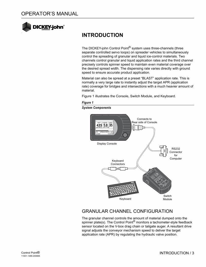
The DICKEY-john Control Point® system uses three-channels (three separate controlled servo loops) on spreader vehicles to simultaneously control the spreading of granular and liquid ice-control materials. Two channels control granular and liquid application rates and the third channel precisely controls spinner speed to maintain even material coverage over the desired spread width. The dispensing rate varies directly with ground speed to ensure accurate product application.
Material can also be spread at a preset “BLAST” application rate. This is normally a very large rate to instantly adjust the target APR (application rate) coverage for bridges and intersections with a much heavier amount of material.
Figure 1 illustrates the Console, Switch Module, and Keyboard.
Figure 1System Components
GRANULAR CHANNEL CONFIGURATIONThe granular channel controls the amount of material dumped onto the spinner plate(s). The Control Point® monitors a tachometer-style feedback sensor located on the V-box drag chain or tailgate auger. A resultant drive signal adjusts the conveyor mechanism speed to deliver the target application rate (APR) by regulating the hydraulic valve position.
435SALT
LBS/MILE
LIQUID
GAL/TON
MPH
0% 100%SPREAD WIDTH8 MAR 12:25:PM
1 2 3 4 5 6 7 8 9 0- =
Q W E R T Y UI O P
[ ] \
A S D F G H J K L; '
BackSpace
Z X C VB N M
,. /
RS232
Connector
for
Computer
Display Console
Keyboard
Connectors
Switch
ModuleKeyboard
Connects to
Rear side of Console
OFF AUTO UNLOAD
MASTER
0
0
40
60
80
100
BLAST

OPERATOR’S MANUAL
Control Point®11001-1489-200806
4 / INTRODUCTION
LIQUID CHANNEL CONFIGURATIONThe liquid channel controls the application rate of pre-wetting or de-icing materials. When pre-wetting, the Control Point® console monitors a flowmeter-style feedback sensor. Flowmeter feedback can be used when de-icing. Using feedback data, the pumping mechanism output adjusts the target application rate by either regulating pump speed or flow blocking.
De-icing systems use up to five boom inputs for applying material to more than one lane at a time.
SPINNER CHANNEL CONFIGURATIONThe spinner channel controls the spinner plate(s) speed with either a closed-loop (precision) or an open-loop configuration. In the closed-loop configuration, a tachometer style feedback sensor, mounted on the spinner assembly, monitors spinner activity. Using the feedback data, the spinner mechanism speed adjusts for the target setting by controlling the hydraulic valve position. In open loop systems, the hydraulic valve position is relative to the width adjust knob setting on the Control Point® Switch Module.
The user must determine the spread-width accuracy needed. Technical assistance is available through DICKEY-john Technical Support at PH#1-800-637-2952.
PRODUCT APPLICATION MECHANISMSThe granular and spinner channels use, in addition to feedback (shaft rotation) sensors, proportional valves to control the product application and spinner speed. The liquid channel uses, in addition to feedback sensors (flowmeter), a liquid pump to control product application. The liquid pump output is controlled by either a 12 volt DC motor, servo valve actuator, or proportional valve.
Features:
1. Surface-mount console kit for ease of installation.2. Flexible Switch Module design allows mounting anywhere in the cab
for optimal operator use.3. Large 160X128 dot-matrix LCD display with backlighting for nighttime
viewing.4. Single Console button for system power on/off and screen selection.5. RS-232 port for PC uploading and downloading of data.6. Detachable keyboard for easy supervisor programming and calibration
using multilevel, menu-driven screens.7. Custom programming available to minimize setup time.8. Compatibility with a variety of sensors, servo valve actuators, and
proportional valves available from DICKEY-john or other manufacturers.
9. Audible and visual alarms for system and operator errors.

OPERATOR’S MANUAL
Control Point®11001-1489-200806
INTRODUCTION / 5
SYSTEM COMPONENTSA DICKEY-john Control Point® system consists of six basic components:
1. Console2. Switch module3. Ground speed sensor4. Feedback devices to monitor material application5. Valve control devices to regulate material application6. Harnesses to interconnect all system devices
NOTE: The detachable keyboard (optional) and PC (not provided) are programming aids and are not part of a basic Control Point® system.
Figure 2 shows components in a block diagram. The Console and Switch Module are to be mounted inside the truck cab either side-by-side or the Switch Module positioned elsewhere for operator convenience.
Figure 2System Block Diagram
CONSOLEThe Console displays information on a dot-matrix LCD and uses a single push-button switch to control system power and to view several operator screens. Using an external keyboard for programming and placing operator controls on the Switch Module simplifies the Console.
CONSOLE
• Store User Entered and
Accumulated Data
• Transfer User Entered and
Accumulated Data
• Display APRs (2)
• Display Spread Width
• Display Ground Speed
• Display Time & Date
• Display Current Totals
• Display Season Totals
• Control 3 Channels
KEYBOARD
• Alphanumeric Data Entry
• Program, Calibrate
• Service Access
SWITCH MODULE
• Master OFF/AUTO/UNLOAD
• Channel ON/OFF
• Channel APR INC/DEC
• BLAST Switch
• Spread WIDTH ADJUST Knob
3 Channel
Actuators
Gnd Spd
Sensor
3-Pulsed Feedback
Sensors
3-Analog Feedback
Sensors
RS232 Port
OPERATOR’S MANUAL
Control Point®11001-1489-200806
6 / INTRODUCTION
An RS-232 port connector, located on the Switch Module harness, permits data transfer to and from the Console. This port interfaces to a PC for downloading accumulator and alarm information. Uploading and downloading configuration information through the port allows data transfer between consoles (replacing a console or when identical vehicles require programming/calibration). For multiple units, only one system needs to be programmed and then the constants can be transferred (downloaded) from that console, stored in a PC file, and uploaded to the other vehicle's console. Note: This is only useful on identical vehicles. Transferring data does not fine-tune each system. It is recommended to run System Response (F11) if constants are uploaded from another console.
SWITCH MODULEStandardThe Standard Switch Module harness plugs into the Console and contains connectors for both keyboard and PC interface as described above. The operator controls the real-time functions of the Control Point® system from the seven switches on the Switch Module (refer to Figure 3).
WirelessThe Wireless Switch Module is similar to the Standard, however, it provides for data transfer to a PC via a wireless transmission to a base station.
KEYBOARDThe keyboard is used to program and calibrate the system. The 86-key, alphanumeric, PC-compatible keyboard has been environmentally hardened for use in the ice-control field. After programming and calibration are finished, the keyboard is usually disconnected and stored.
GROUND SPEED SENSORThe ground speed sensor generates vehicle speed information for the console. Sensor electrical pulses proportional to the vehicle ground speed are vital to system operation because true vehicle ground speed is necessary for accurate product application. The system can function with a wide variety of electronic and mechanical speedometer sensors, including Hall-Effect and Reluctance sensors.
FEEDBACK SENSORSThe feedback sensors send product flow information to the console for accurate product application. Both granular and spinner channels require pulsed electrical sensors having an output proportional to the mechanism speed. The liquid channel accepts either electrical-pulsed sensors or analog sensors with outputs proportional to material flow (pulsed). A liquid prewetting system only accepts pulsed feedback while higher capacity anti-icing systems accept either pulsed or analog.

OPERATOR’S MANUAL
Control Point®11001-1489-200806
INTRODUCTION / 7
VALVE CONTROL DEVICESValve Control devices regulate material flow for accurate control of product application rates. Normally, granular and spinner channels regulate the hydraulic oil flow rate to a motor. Liquid channels use several different configurations.
HOPPER LEVEL SENSOR (OPTIONAL)The optical light beam of this level sensor is blocked by the granular material in the spreader bed. When the material level falls beneath the sensor mounting level, a repetitive beep sounds and an appropriate message displays in the warning/alarm area of the Operate screen.
HARNESSESMain Harness Assembly-Connects the Console to the ground speed sensor, feedback sensors, channel valve (or DC motor) actuators, vehicle battery, ignition, and additional optional connections (including two-speed axle, hopper level sensor, and boom sense inputs).
Retro Harness Assembly-Connects a Control Point console to an ICS2000 harness (refer to Figure 53 in Troubleshooting section).
Other extension harnesses-Other extension harnesses are available that allow for flexible sensor arrangement. Contact Technical Support for harnessing alternatives.
TECHNICAL SUPPORTFor technical assistance, call DICKEY-john Technical Support at (217) 438-3371 or Fax (217) 438-6012 or 438-6539. For toll-free calls in either the USA or Canada, dial 1-800-637-3302.
OPERATOR’S MANUAL
Control Point®11001-1489-200806
8 / INTRODUCTION

OPERATOR’S MANUAL
Control Point®11001-1489-200806
SYSTEM INSTALLATION / 9
SYSTEM INSTALLATION
The Console mounts on the vehicle dashboard or other surface suitable for operator viewing using a U-bracket. The standard (combination) mounting plate secures the Switch Module immediately to the left of the Console. An optional mounting plate mounts the Console only.
The Switch Module cable, which plugs into the Console, is long enough to allow the Switch Module to be placed near the vehicle seat or elsewhere for operator convenience. If the combination mounting plate is used, the option remains to later remove the Switch Module from the mounting plate and to relocate it for convenience.
The system main harness is laid out and connections are made to the sensor and actuator cables, battery, ignition switch, and additional options (two-speed axle, hopper level sensor, and boom sense inputs), as required.
Verify all items in the appropriate hardware mounting kit are present:
HARDWARE KITS
STANDARD HARDWARE KIT (46649-0380) FOR CONSOLE AND SWITCH MODULE: (1) Combination mounting plate (46649-0580)(2) U-bracket (46649-0590)(3) Two 1/4 - 20 x 1 inch hex bolts(4) Five 1/4 inch split washers(5) Two rubber washers (46390-0900)(6) Two knob screws (20072-0022)(7) Three 1/4 - 20 x 3/4 inch hex bolts(8) Retaining clip (46649-0350)(9) Two #6 self-locking hex nuts(10) Three #6 plastite screws
OPTIONAL HARDWARE KIT (46649-0390) FOR CONSOLE ONLY:(1) Console mounting plate (46649-0370)(2) U-bracket (46649-0590)(3) Two 1/4 - 20 x 1 inch hex bolts(4) Five 1/4 inch split washers(5) Two rubber washers (46390-0900)(6) Two knob screws (20072-0022)(7) Three 1/4 - 20 x 3/4 hex bolts(8) Retaining clip (46649-0350)(9) Two #6 self-locking hex nuts
OPERATOR’S MANUAL
Control Point®11001-1489-200806
10 / SYSTEM INSTALLATION
CONSOLE PLACEMENTThe Console mounts inside the cab on any surface permitting easy readability of the display without obstructing the operator’s view to the road while driving (See Figure 3). Be sure the opposite side of the mounting surface chosen has clearance for installing and tightening the mounting bolts. The combination mounting plate positions the Switch Module to the left of the Console.
U-BRACKET MOUNTING1. Place the U-bracket in the exact location for mounting and mark both
drill holes with a pencil or scribe. If the Console is being mounted on the dash, move and secure wiring and other obstructions located beneath the dash.
2. Drill two 9/32 inch holes. 3. Position the U-bracket in place on the mounting surface and insert the
two 1 inch bolts. 4. Install the lock washers and nuts and tighten them.
CONSOLE AND SWITCH MODULE INSTALLATION1. Install the Console onto the mounting plate using three 3/4 inch bolts
and lock washers. 2. When using the combination mounting plate, install the Switch Module
onto the mounting plate using three plastite screws. 3. Two sets of holes exist in the mounting plate to allow for optional
spacing between the Switch Module and Console. If only the Console mounting plate is used, install the Switch Module at the desired location. If placed on the vehicle seat, it must be secured in a suitable manner (possibly using Velcro™ strips) to ensure the control settings are not accidently changed or activated.

OPERATOR’S MANUAL
Control Point®11001-1489-200806
SYSTEM INSTALLATION / 11
Figure 3Console Mounting
SWITCH MODULE TO CONSOLE CONNECTION 1. Plug the circular connector of the Switch Module cable into the rear of
the Console, rotating the connector collar fully-clockwise to lock it.2. Place the keyboard mating connector (with its pins pointing upward)
between the two studs on the rear of the mounting plate. Capture this connector with the retaining clip and two self-locking nuts. The 9-pin RS-232 connector can be secured to the Switch Module cable with a cable tie, if desired. Figure 1 shows how the Switch Module cable connects to the Console and keyboard.
CONSOLE MOUNTING1. Secure the Console and mounting plate (and Switch Module if the
combination mounting plate is being used) to the U-bracket using the two knob screws. The rubber washers fit between the U-bracket and the mounting plate tabs.
2. Pivot the Console for the best viewing angle and tighten the two knob screws.
HARNESS CONNECTION1. Verify all required “exterior system cables” are installed on the
spreader vehicle according to their separate, individual instructions. These are defined as the sensor, actuator, ground speed, boom sense, and hopper level cables.
2. Use dust caps provided on all unused connectors, both internal and external. This includes keyboard and RS-232 connectors.
U-Bracket
(46649-0590)
Combination
Mounting Plate
(46649-0580)
Optional Console Only
Mounting Plate
(46649-0370)#6 Self-Locking
Hex Nuts#6 Self-Locking
Hex Nuts
#6 x 1/2 inch
Plastite Screws
Knob Screw
(20072-0022)
Knob
Screw
(20072-0022)
1/4-20 x 3/4 Inch
Hex Bolts &
Lockwashers
1/4-20 x 3/4 inch
Hex Bolts &
Lockwashers
Retaining Clip
(holds Switch Mod
keybd connector)
(46649-0350)
Note: Mounting hardware for securing
mounting bracket to dash/mounting
panel are not supplied with kit.

OPERATOR’S MANUAL
Control Point®11001-1489-200806
12 / SYSTEM INSTALLATION
NOTE: Labels have been supplied in the dust cap kit to be placed on external extension cables routed to the flowmeter, granular and spinner sensors.
Make the Control Point® battery connections last to ensure no accidental shorts occur during harness handling.
MAIN HARNESS CONNECTION 1. Plug the largest circular connector of the main harness into the
Console, rotating the connector collar fully-clockwise to lock it. 2. Route the harness to a clean, safe area (inside the cab) suitable for
connection to the exterior system cables (from the sensors and actuators). All connectors on the main harness are identified with labels to simplify hookup. If a suitable “punch-out” hole in the rear cab wall or floor is not available to bring in the exterior system cables, cut a hole approximately two and one-half (21/2) inches in diameter. The edges of this hole should be covered with a piece of plastic or rubber U-channel material to protect the insulation of the cables passing through the hole. Anchor all cables suitable with nylon cable ties to prevent damage due to flexing and scraping. RTV or silicone caulk can be used to seal the hole.
Do not connect the RED ignition lead directly to the battery voltage. This will prevent the system from storing data properly!
3. Connect the RED ignition lead to the “switched” terminal of the ignition switch. The correct terminal is at 12 volts DC or higher only when the ignition switch is turned on.
4. If the vehicle has a two-speed axle, connect the terminal of the YELLOW 2-Speed Axle lead to the appropriate terminal on the axle-shifter switch.
5. If the vehicle does not have a two-speed axle, insulate the terminal with electrical tape and tie back this YELLOW lead with a cable tie.
6. Connect the hopper level sensor and boom sense inputs, if used. The Boom Sense 5 (gray wire) line can be connected to a pre-wet/anti-ice selector input switch.
Verify battery voltage is 12 volts, NOT 24 volts.
7. Connect both Control Point® main harness battery leads directly to the vehicle battery. Attach the RED wire to the positive battery terminal and the BLACK wire to the negative terminal.
IMPORTANT: Use dust caps provided on all unused connectors, both internal and external. This includes keyboard and RS-232 connectors.
OPERATOR’S MANUAL
Control Point®11001-1489-200806
SYSTEM INSTALLATION / 13
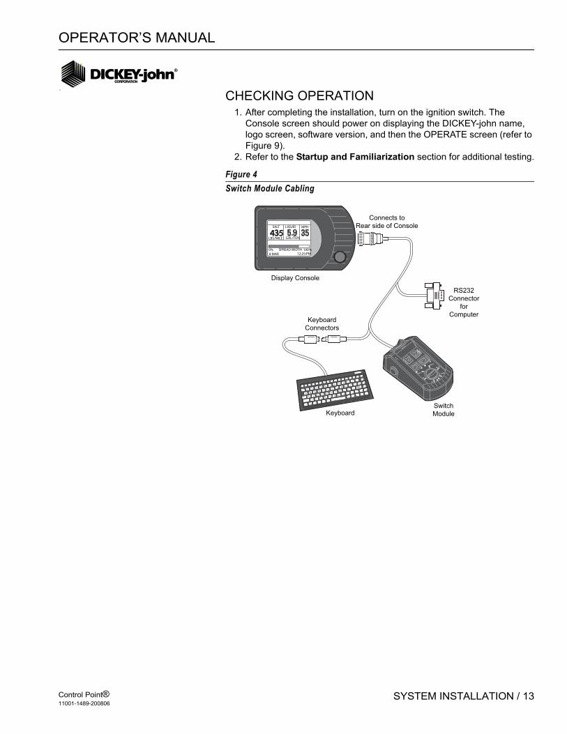
CHECKING OPERATION1. After completing the installation, turn on the ignition switch. The
Console screen should power on displaying the DICKEY-john name, logo screen, software version, and then the OPERATE screen (refer to Figure 9).
2. Refer to the Startup and Familiarization section for additional testing.
Figure 4Switch Module Cabling
435SALT
LBS/MILE
LIQUID
GAL/TON
MPH
0% 100%SPREAD WIDTH8 MAR 12:25:PM
1 2 3 4 5 6 7 8 9 0- =
Q W E R T Y UI O P
[ ] \
A S D F G H J K L; '
BackSpace
Z X C VB N M
,. /
RS232
Connector
for
Computer
Display Console
Keyboard
Connectors
Switch
ModuleKeyboard
Connects to
Rear side of Console
OFF AUTO UNLOAD
MASTER
0
0
40
60
80
100
BLAST

OPERATOR’S MANUAL
Control Point®11001-1489-200806
14 / SYSTEM INSTALLATION
Figure 5System Harness Layout
Gnd SpeedSensor
Hopper LevelSensor
+
Battery
Ð
Boom
Sensors
Flowmeter
Tank Level
or
Down Pressure
Granular
Application Rate
Sensor
Spinner
Sensor
Liquid
Valve
Granular
(& Spinner)
2 Speed Axle
Ignition
Alternate sets of connectors
(Insulate and tie back
unused connectors)
CPC connector Main
Harness
12V Relay
Gate HeightSensor
Road WatchAdapter
OPERATOR’S MANUAL
Control Point®11001-1489-200806
START-UP AND FAMILIARIZATION / 15
START-UP AND FAMILIARIZATION
This section defines how the operator (driver) of an ice-control vehicle uses the controls on the Switch Module and Console to perform standard operator functions.
NOTE: The detachable keyboard (optional) is required to program and calibrate the system as described in Keyboard Programming.
Programming during setup allows the operator to view three or four different screens of data. The Operate screen is the home screen for monitoring spreader operation and the remaining screens are supportive.
• Material Select/Manual Speed (accessible only when system is stationary; no ground speed)
• Current Totals• Season Totals
START-UP PREPARATIONThe system must be installed, programmed, and calibrated before performing the following procedures.
IMPORTANT: Practice the following procedures with the vehicle stationary to gain familiarity with the operating controls and screens before applying product.
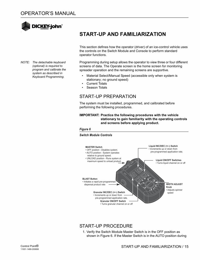
Figure 6
Switch Module Controls
START-UP PROCEDURE1. Verify the Switch Module Master Switch is in the OFF position as
shown in Figure 6. If the Master Switch is in the AUTO position during
OFF
AUTO
UNLOAD
MASTER
0
0
40
60
80
100
BLAST
MASTER Switch
• OFF position - Disables system.
• AUTO position - System operates
relative to ground speed.
• UNLOAD position - Runs system at
maximum speed to unload product.
BLAST Button
• Initiates a rapid pre-programmed
dispersal product rate
Liquid ON/OFF Switches
• Turns liquid channel on or off
Granular ON/OFF Switch
• Turns granular channel on or off
WIDTH ADJUST
Knob
• Adjusts spinner
speed
Liquid INC/DEC (+/–) Switch
• Increments up or down from
pre-programmed application rate.
Granular INC/DEC (+/–) Switch
• Increments up or down from
pre-programmed application rate.
OPERATOR’S MANUAL
Control Point®11001-1489-200806
16 / START-UP AND FAMILIARIZATION
power up, a warning message with audible alarm occurs until the switch is turned OFF (refer to Figure 7).
Figure 7Master Switch Warning Message
2. Turn on the ignition switch. If the Console is kept ON when the truck ignition is turned off, the next power on cycle will automatically turn ON the Console display.
3. If the Console does not power on during truck startup, the console button was pressed and held until unit powered OFF before the truck was turned OFF.
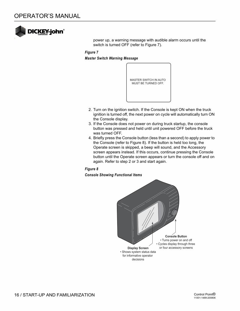
4. Briefly press the Console button (less than a second) to apply power to the Console (refer to Figure 8). If the button is held too long, the Operate screen is skipped, a beep will sound, and the Accessory screen appears instead. If this occurs, continue pressing the Console button until the Operate screen appears or turn the console off and on again. Refer to step 2 or 3 and start again.
Figure 8Console Showing Functional Items
MASTER SWITCH IN AUTO
MUST BE TURNED OFF.
Console Button
• Turns power on and off
• Cycles display through three
or four accessory screensDisplay Screen
• Shows system status data
for informative operator
decisions

OPERATOR’S MANUAL
Control Point®11001-1489-200806
START-UP AND FAMILIARIZATION / 17
5. The Console automatically closes all system actuators and performs self-tests, including system configuration and application data during start up. If an error occurs at power up or during operation, an appropriate error message displays with recovery information for approximately 4 seconds.
6. Turn the Console off by pressing and holding the Console button until a beep and text on the screen disappears (approx. 3 seconds); and then release. Power is removed when the screen goes dark. To restart, repeat step 2.
Figure 9Operate Screen Display
OPERATE SCREEN DISPLAY FUNCTIONSThe upper display includes three windows for Granular, Liquid, and true (actual) Ground Speed data. Status of the booms graphically display at top. Below the windows, error messages appear briefly for system errors and an audible alarm. The display bottom shows the Spread Width Bar indicating percentage of spinner activity via a black bar. The current date and time is also displayed at the bottom of the screen.
1. If the Granular and Liquid ON/OFF switches are turned off and back on, the window for each product reads OFF and then returns to the material and target (APR) values again.
NOTE: Large font on the Operate screen indicates the control is active. Small font indicates the control is not active.
Ground speed is independent of product application and therefore displays only when the vehicle is moving. Product application begins with vehicle motion if the Master Switch is in the AUTO position. The actual APRs display almost twice the size of the target APRs (refer to Figure 7).
2. The target rate of either product channel can be changed by pressing the respective INC/DEC +/- switch on the Switch Module. The value increments or decrements with an audible beep for each step. If the
SALT LIQUID 1 MPH
0LBS / MILE GAL / TON
APPLICATION RATE ERRORSPINNER
SPREAD WIDTH 100%
9 : 15 AM
500 4.50
0%
26 AUG 06
Granular Channel Window• Displays target application rate
(APR) with vehicle stationary,
actual application rate when
spreading material.
• Displays OFF when
Granular ON/OFF switch
is turned to OFF.
Liquid Channel Window• Displays target application rate (APR) with vehicle
stationary, actual application rate when spraying liquid.
• Displays OFF when Liquid ON/OFF switch
is turned to OFF.
Current Time• Maintains/retains current time.
Current Date• Maintains/retains correct date.
Error/Alarm Zone• Displays message to
instruct operator action.
Ground Speed Window• Indicates rate of travel at all times.
Four Boom Section indicators• Black indicates active boom section.
• 0 in first boom indicates pressure sensor
reading zero at this time and non-active.
• No boom indicators mean channel is set
as pre-wet.
Spread Width Bar• Black indicates spinner operation
and spread width in percent. Value is
adjusted using the Spread Width
knob on the Switch Module.
0
OPERATOR’S MANUAL
Control Point®11001-1489-200806
18 / START-UP AND FAMILIARIZATION
switch is held, the value repeats until reaching a preset limit. If changed while the vehicle is moving, the new target APR displays for approximately two seconds, then reverts to the actual APRs.
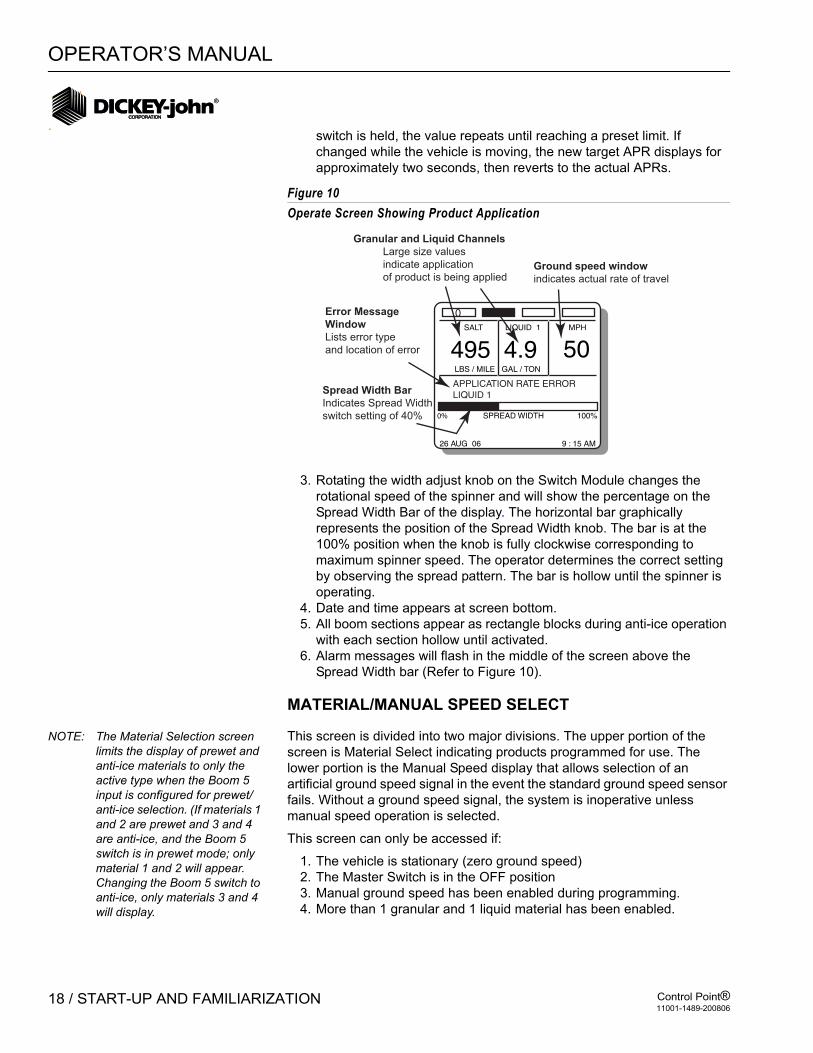
Figure 10Operate Screen Showing Product Application
3. Rotating the width adjust knob on the Switch Module changes the rotational speed of the spinner and will show the percentage on the Spread Width Bar of the display. The horizontal bar graphically represents the position of the Spread Width knob. The bar is at the 100% position when the knob is fully clockwise corresponding to maximum spinner speed. The operator determines the correct setting by observing the spread pattern. The bar is hollow until the spinner is operating.
4. Date and time appears at screen bottom.5. All boom sections appear as rectangle blocks during anti-ice operation
with each section hollow until activated.6. Alarm messages will flash in the middle of the screen above the
Spread Width bar (Refer to Figure 10).
MATERIAL/MANUAL SPEED SELECT
NOTE: The Material Selection screen limits the display of prewet and anti-ice materials to only the active type when the Boom 5 input is configured for prewet/anti-ice selection. (If materials 1 and 2 are prewet and 3 and 4 are anti-ice, and the Boom 5 switch is in prewet mode; only material 1 and 2 will appear. Changing the Boom 5 switch to anti-ice, only materials 3 and 4 will display.
This screen is divided into two major divisions. The upper portion of the screen is Material Select indicating products programmed for use. The lower portion is the Manual Speed display that allows selection of an artificial ground speed signal in the event the standard ground speed sensor fails. Without a ground speed signal, the system is inoperative unless manual speed operation is selected.
This screen can only be accessed if:
1. The vehicle is stationary (zero ground speed)2. The Master Switch is in the OFF position3. Manual ground speed has been enabled during programming.4. More than 1 granular and 1 liquid material has been enabled.
SALT LIQUID 1 MPH
50LBS / MILE GAL / TON
SPREAD WIDTH 100%
9 : 15 AM
495 4.9
0%
26 AUG 06
Ground speed window
indicates actual rate of travel
0
Spread Width Bar
Indicates Spread Width
switch setting of 40%
Granular and Liquid Channels
Large size values
indicate application
of product is being applied
APPLICATION RATE ERRORLIQUID 1
Error Message
Window
Lists error type
and location of error
OPERATOR’S MANUAL
Control Point®11001-1489-200806
START-UP AND FAMILIARIZATION / 19
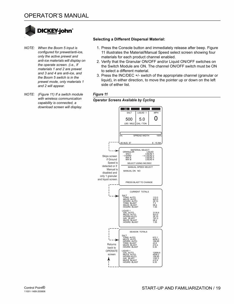
Selecting a Different Dispersal Material:
NOTE: When the Boom 5 input is configured for prewet/anti-ice, only the active prewet and anti-ice materials will display on the operate screen. (i.e., If materials 1 and 2 are prewet and 3 and 4 are anti-ice, and the Boom 5 switch is in the prewet mode, only materials 1 and 2 will appear.
1. Press the Console button and immediately release after beep. Figure 11 illustrates the Material/Manual Speed select screen showing four materials for each product channel enabled.
2. Verify that the Granular ON/OFF and/or Liquid ON/OFF switches on the Switch Module are ON. The channel ON/OFF switch must be ON to select a different material.
3. Press the INC/DEC +/- switch of the appropriate channel (granular or liquid), in either direction, to move the pointer up or down on the left side of either list.
NOTE: (Figure 11) If a switch module with wireless communication capability is connected, a download screen will display.
Figure 11Operator Screens Available by Cycling
SALT LIQUID 1 MPH
0LBS / MILE GAL / TON
SPREAD WIDTH 100%
9 : 15 AM
500 5.0
0%
26 AUG 97
CURRENT TOTALS
SALT TONS AUTO 112.0 MILES AUTO 823.0 HOURS AUTO 26.10 TONS BLAST 7.3 MILES BLAST 68.4 HOURS BLAST 1.55
LIQUID 1 GAL AUTO 2116.6 MILES AUTO 823.0 HOURS AUTO 26.10 GAL BLAST 197.0 MILES BLAST 68.4 HOURS BLAST 1.55
SEASON TOTALS
SALT TONS AUTO 672.1 MILES AUTO 4938.2 HOURS AUTO 156.60 TONS BLAST 43.8 MILES BLAST 410.4 HOURS BLAST 9.35
LIQUID 1 GAL AUTO 12699.6 MILES AUTO 4938.2 HOURS AUTO 156.60 GAL BLAST 1182.3 MILES BLAST 410.4 HOURS BLAST 9.35
MATERIAL SELECTGRANULAR LIQUID SALT LIQUID 1 SAND LIQUID 2 MIX A LIQUID 3 MIX B LIQUID 4
SELECT USING INC/DEC
MANUAL SPEED SELECT
MANUAL ON NO
PRESS BLAST TO CHANGE
Skips screen
if Ground
Speed is
detected or if
Manual is
disabled and
only 1 granular
and liquid screen.
Returns
back to
OPERATE
screen
30

OPERATOR’S MANUAL
Control Point®11001-1489-200806
20 / START-UP AND FAMILIARIZATION
Substituting Manual Speed for Standard Speed SensorIf the ground speed signal is lost, the system ceases to function. A lost signal can occur due to a loss of a sensor, cabling problems, etc. An artificial ground speed signal can be substituted to continue limited operation. The fixed ground speed must be previously programmed and then can be selected from the Material/Manual Speed Select screen (refer to Figure 11).
1. Stop the vehicle and turn the Master Switch OFF. After beep, press and release the Console button on the Operate Screen until the Material Select screen displays.
2. Press the Blast button to change the selection as prompted at the bottom of the screen. MANUAL ON will display. As the Blast button is pressed, NO changes to YES. Releasing the button reverts to the Operate screen. The ground speed window at display bottom now reads MANUAL with a speed that has been programmed.
3. Continue spreading material, maintaining displayed speed as closely as possible, to ensure accurate application. The system spreads material but no accumulators are updated since system accuracy cannot be assured. The related sensor and harness should be inspected and repaired as soon as possible to restore normal operation.
Returning to the Operate Screen1. To cycle back to the Operate screen, press the Console button three
times, waiting for the beep before releasing. The Operate screen will show the material name(s) selected along with the correct (programmed) target APR.
ACCESSING THE CURRENT TOTALS SCREENIf Manual Speed operation has been selected, this must first be de-selected before the Current Totals screen can be cleared.
1. From the Operate screen, press and release the Console button after the beep until the Current Totals screen displays (refer to Figure 12). The Master Switch must be in the OFF position before the Current Totals screen appears showing totals accumulated for the current product selected.To see other totals, return to the Material/Manual Select screen and select those products.

OPERATOR’S MANUAL
Control Point®11001-1489-200806
START-UP AND FAMILIARIZATION / 21
Figure 12Current Totals Screen
CLEARING THE CURRENT TOTALSThe ability to clear the Current Totals screen is programmable in the Programming mode explained in the Keyboard Programming section. If programmed, all totals on this screen should be recorded before clearing, then proceed as follows.
1. With the Granular Switch ON, (upper screen), press the Granular +/- (left) switch up and release when the beep sounds. A message “PRESS DEC TO CONFIRM CLEAR (product) ACCUMS (accumulators)” appears.
2. Press the same switch down (decrement) and the totals reset to zero as shown in Figure 13. To clear the bottom half, repeat the steps for the liquid channel with the Liquid +/- (right) switch (refer to Figure 14). Press the console button to stop the clear operation.
Figure 13Clearing Top Half of Current Totals Screen
CURRENT TOTALS
SALT TONS AUTO 112.0 MILES AUTO 823.0 HOURS AUTO 26.10 TONS BLAST 7.3 MILES BLAST 68.4 HOURS BLAST 1.55
LIQUID 1 GAL AUTO 2116.6 MILES AUTO 823.0 HOURS AUTO 26.10 GAL BLAST 197.0 MILES BLAST 68.4 HOURS BLAST 1.55
Access with Console Button
(Press until beep is heard - once/twice)
CURRENT TOTALS
SALT TONS AUTO 112.0 MILES AUTO 823.0 HOURS AUTO 26.10 TONS BLAST 7.3 MILES BLAST 68.4 HOURS BLAST 1.55
From CURRENT TOTALS Screen, use Granular +/– switch to change(Press up to access, down to clear)
PRESS DEC TO CONFIRM CLEAR SALT ACCUMS

OPERATOR’S MANUAL
Control Point®11001-1489-200806
22 / START-UP AND FAMILIARIZATION
Figure 14Clearing Bottom Half of Current Totals Screen
ACCESSING THE SEASON TOTALS SCREEN1. From the Operate screen, press the Console button and release after
the beep. Repeat until the Seasons Total screen appears (refer to Figure 15). This screen shows the amount of material applied, miles traveled during application, and hours elapsed this season for each product in both the Auto and Blast modes. The totals can only be cleared in the Program Mode (keyboard).
Figure 15Season Total Screen
USING THE BLAST BUTTONPressing the red Blast button (on the left side of the Switch Module) causes material to dispense at a higher, programmed rate. The BLAST button performs several functions, depending upon programming options.
1. With the Operate screen displaying, press the Blast button on the side of the Switch Module.When the Blast button is pressed, the Operate screen displays BLAST ON above the Spread Width bar.This either initiates a timed blast cycle (programmed length) or momentary (blasts
CURRENT TOTALS
PRESS DEC TO CONFIRM CLEAR LIQUID 1 ACCUMS
LIQUID 1 GAL AUTO 2116.6 MILES AUTO 823.0 HOURS AUTO 26.10 GAL BLAST 197.0 MILES BLAST 68.4 HOURS BLAST 1.55
From CURRENT TOTALS Screen, use Liquid +/– switch to change
(Press up to access, down to clear)
SEASON TOTALS
SALT TONS AUTO 672.1 MILES AUTO 4938.2 HOURS AUTO 156.60 TONS BLAST 43.8 MILES BLAST 410.4 HOURS BLAST 9.35
LIQUID 1 GAL AUTO 12699.6 MILES AUTO 4938.2 HOURS AUTO 156.60 GAL BLAST 1182.3 MILES BLAST 410.4 HOURS BLAST 9.35
Access from OPERATE Screen(Press Console Button 2/3 times)

OPERATOR’S MANUAL
Control Point®11001-1489-200806
START-UP AND FAMILIARIZATION / 23
only with the button pressed). A timed blast period can be terminated early by activating the Blast button a second time. Blasting can be initiated with the master switch in AUTO or OFF.With a timed blast cycle, a programmed minimum ground speed establishes the material flow rate until that speed is exceeded by the actual ground speed.
MASTER SWITCH IN THE UNLOAD POSITIONThe Unload position of the master switch is used to quickly remove material from the truck. There must be no ground speed for the Unload function to operate. If ground speed is dedicated, the Unload feature will not work.
If the spinner is programmed to operate during UNLOAD, be sure that no one is in the vicinity before performing this procedure to avoid possible injury!
1. Back up to the appropriate location and momentarily press Unload.The actuators open fully for those channels turned on from the Switch Module.
2. To stop the unload operation, move the master switch to the OFF position.
3. If ground speed exceeds longer than 10 seconds, unload will be terminated. To clear, move the master switch to OFF.

OPERATOR’S MANUAL
Control Point®11001-1489-200806
24 / START-UP AND FAMILIARIZATION

OPERATOR’S MANUAL
Control Point®11001-1489-200806
KEYBOARD PROGRAMMING / 25
KEYBOARD PROGRAMMING
Programming allows the operator to enter rates, limits, and other parameters into the Control Point® memory for regulating system product application. These parameters are entered through a detachable keyboard.
Programmable parameters include:
1. Calibration Constants2. Configuration Parameters (sensor and actuator specifications)3. Granular and Liquid Material Information4. Product Application Rates (APRs)
Resetting System Accumulators for vehicle mileage, material usage, and time totals is also available.
NOTE: 6.3 and older configuration files cannot be loaded into a Control Point® programmed with 6.40 and newer software versions. Contact Dickey-john Technical Support for additional information.
Programming must be performed before attempting system calibration. Accurate system calibration constants are determined through regular calibration routines. However, known constants at the time of programming can be entered reducing the calibration procedures required. Calibration corrections can be revised anytime to fine tune accuracy.
LOGGING CONFIGURATION DATAIn the event of Console damage, lost data, upgrading software, or replacement, all calibration constants and other system parameters should be recorded.
For Control Point’s® using software versions older than 7.27, Calibration Data Sheets are provided at the rear of this manual.
Control Points® with 7.27 or higher versions can download Control Point configurations to the computer’s hard drive via wireless transfer and reload back to the Control Point® without using the keyboard.
PRE-PROGRAMMINGEach Control Point® system is shipped from DICKEY-john pre-programmed. Specific parameters can be custom pre-programmed by DICKEY-john to minimize customer programming. This simplifies calibration but final System Response must be performed after installation on every truck (see System Calibration section).

OPERATOR’S MANUAL
Control Point®11001-1489-200806
26 / KEYBOARD PROGRAMMING
Figure 16Keyboard Layout and Functions
USING THE KEYBOARD AND SCREENSProgramming and calibration is accomplished using the keyboard and on-screen, menu-driven instructions. The keyboard detaches and can be stored after programming and calibration is complete. To use the keyboard, proceed as follows:
1. If the Control Point® is on, turn the power off and then connect the keyboard to the console harness connector (refer to Figure 1).
2. Place the Master Switch on the Switch Module in the OFF position and turn the power back ON. Each time power is applied, the Operate Mode (F1) comes up and normal system operation can be performed. However, the remaining functions (F2 through F12) cannot be selected unless the master dwitch is in the OFF position.
3. The decal immediately above the function keys, F1 through F12, identifies each function. Pressing any F-key immediately enters and displays that function. Transferring to another function can be done by pressing another F-key.
4. Basic screen layout includes:
Function screen (top level) – Each screen lists items with numbers to the left side (except F8). Pressing the indicated key number displays that screen, usually one with parameters for editing.
Parameter screens (second level) – An index arrow appears to the left of the first item and an underscore beneath the first digit of that parameter.
P
Esc F1 F2 F3 F4 F5 F6 F7 F8 F9 F10 F11 F12 NumLock
PrtScSysRc
ScrollLock
PauseBreak
1!
2 3 4 5 6 7 7 8 8 9 9 0
@ # $ % ^ & *
*
( ) _ + BackSpace Home- =
Q W E R T Y U I O { } |4 5 6 _ [ ] \
A S D F G H J K L : "Enter
EnterCapsLock 1 2 3 +
PgDn
ShiftZ X C V B N M < > ?
Shift, . / /0End
Alt Ins DelFn Ctrl Alt ~`
OPERATEGRANULAR
APPL RATE
GRANULAR
CONFIG.
LIQUID
CONFIG.
LIQUID
APPL
RATECAL
GROUND
SPEEDSPINNER ACCUM
SYSTEM
RESP.
SYSTEM
INFO.MISC.
Function Labels
• Identifies each Function key
Function Keys
• Selects each Function
Number Keys
• Selects Parameter from screen list
• Also used to insert values into screens
Alpha Keys
• Used for labels
• Used to make selections
Other Keys
• ENTER – Accepts an entry
• BACKSPACE –Deletes or backs up
• Up/Down Arrows – Selects items on editing screens
• ESC – Displays the next higher level screen
TM

OPERATOR’S MANUAL
Control Point®11001-1489-200806
KEYBOARD PROGRAMMING / 27
Figure 17Basic Screens Layout
Editing a parameter – The up and down arrow keys move the index arrow to other parameters for editing. To change the selected parameter, key in the desired value. When finished, press the Enter key to accept the new value and advance the index arrow to the next line. Failing to use the Enter key (except for YES/NO and serial port configurations) loses the new value.
Other keys – The Backspace key erases incorrectly keyed numbers or text. To restore previous values after keying in a new number, press either arrow key instead of Enter. Invalid keystrokes are not accepted for entry and cause an audible warning.
Pressing the Escape key returns to the previous screen. Pressing any function key (F1 through F12) transfers directly to that function.
Screen prompts – If “MORE...” appears on a screen, additional parameters are on an extended screen. Access this screen by moving the index arrow to the “MORE...” line (refer to Figure 18).
MISCELLANEOUS MENU SELECT A MENU ITEM
1 BLAST SETUP
2 TIME / DATE
3 SYSTEM UNITS
4 SERIAL PORT CONFIGURATION
5 CHANGE LANGUAGE
6 SERVICE MENU
PROGRAM TIME / DATE 24 HOUR NOHOUR 6MINUTES 39AM / PM PMONTH 11DAY 26YEAR 98
• First level after
pressing Function key Parameter Screen• second level after
selecting menu item number
Index Arrow•Selects parameter to edit
Parameter Subject List• Each line is selected
separately with index arrow
Parameters for Editing• Numbers are changed using
the number keys,
• Words are changed by typing
first letter or keying some words
Note: In some cases, a Sub-Function screen appears
between the Function and Parameter screens
with additional selections.
OPERATOR’S MANUAL
Control Point®11001-1489-200806
28 / KEYBOARD PROGRAMMING
5. All programming steps should be performed in the order outlined in this manual to ensure proper entries for all parameters. The master switch must be OFF before functions can be selected with the keyboard.
OPERATOR’S MANUAL
Control Point®11001-1489-200806
KEYBOARD PROGRAMMING / 29
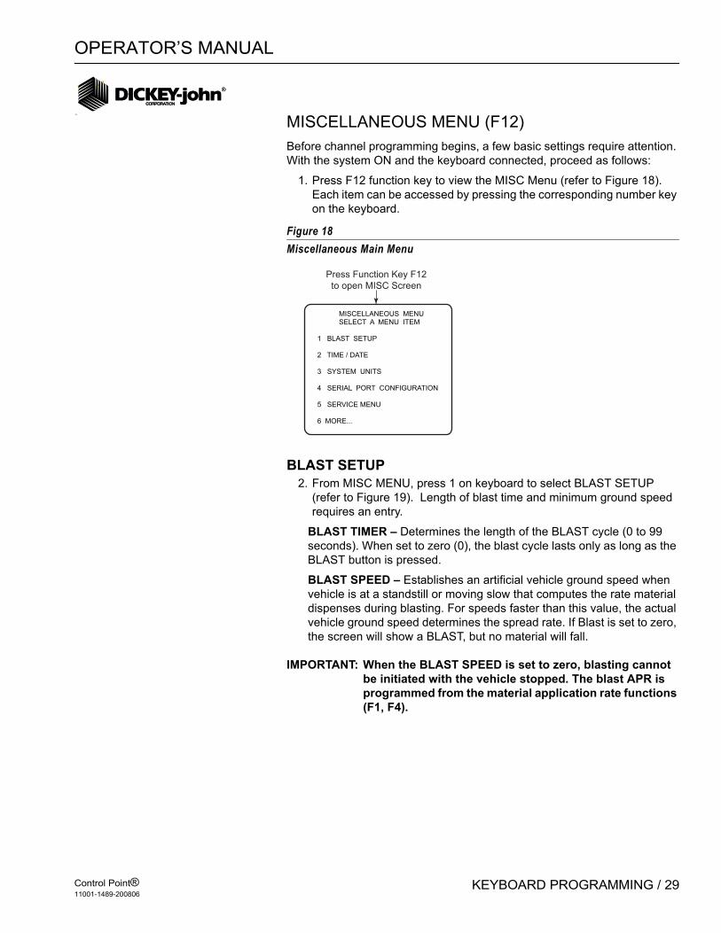
MISCELLANEOUS MENU (F12)Before channel programming begins, a few basic settings require attention. With the system ON and the keyboard connected, proceed as follows:
1. Press F12 function key to view the MISC Menu (refer to Figure 18). Each item can be accessed by pressing the corresponding number key on the keyboard.
Figure 18Miscellaneous Main Menu
BLAST SETUP2. From MISC MENU, press 1 on keyboard to select BLAST SETUP
(refer to Figure 19). Length of blast time and minimum ground speed requires an entry.
BLAST TIMER – Determines the length of the BLAST cycle (0 to 99 seconds). When set to zero (0), the blast cycle lasts only as long as the BLAST button is pressed.
BLAST SPEED – Establishes an artificial vehicle ground speed when vehicle is at a standstill or moving slow that computes the rate material dispenses during blasting. For speeds faster than this value, the actual vehicle ground speed determines the spread rate. If Blast is set to zero, the screen will show a BLAST, but no material will fall.
IMPORTANT: When the BLAST SPEED is set to zero, blasting cannot be initiated with the vehicle stopped. The blast APR is programmed from the material application rate functions (F1, F4).
MISCELLANEOUS MENU SELECT A MENU ITEM
1 BLAST SETUP
2 TIME / DATE
3 SYSTEM UNITS
4 SERIAL PORT CONFIGURATION
5 SERVICE MENU
6 MORE...
Press Function Key F12
to open MISC Screen

OPERATOR’S MANUAL
Control Point®11001-1489-200806
30 / KEYBOARD PROGRAMMING
Figure 19Verifying Blast Setup Menu Adjustments
TIME/DATE SETUP3. Press F12 function key to return to the Misc Menu and select Time/
Date (2), refer to Figure 20.
Verify or correct the following settings:– 24 HOUR – Press (Y) YES for 24 hour time; (N) NO for standard 12
hour time.– HOUR – Enter the correct hour.– MINUTES – Enter the correct minutes.– AM/PM – Enter A for AM or P for PM (This selection does not
appear for 24 hour time).– MONTH –Enter the correct numerical month.– DAY – Enter the correct day of the month.– YEAR – Enter the last two digits of the year.
Figure 20Setting Time and Date
SYSTEM UNITS4. Select F12 to return to the Misc Menu and select System Units (3)
(refer to Figure 21).The System Units screen allows either English or
BLAST SETUP
BLAST TIMER 10 SECONDSBLAST SPEED 5.0 MPH
Select Item 1
from F12 Function Screen
(MISC Screen)
PROGRAM TIME / DATE 24 HOUR NOHOUR 6MINUTES 39AM / PM PMONTH 8DAY 26YEAR 6
Select Item 2
from F12 Function Screen
(MISC Screen)
.

OPERATOR’S MANUAL
Control Point®11001-1489-200806
KEYBOARD PROGRAMMING / 31
Metric units. Parameter values will change on all screens immediately and convert to the equivalent numerical values.
– Select either Y(YES) or N(NO). Y changes units to metric; N retains the units in English.
– After selecting English or Metric, select units of measure from the remaining list.
English choices available are miles, miles-feet, square feet, or square yards and 1000/ft2.
Metric choices are kilometers, kilometers-meter, square meter and kg square meter. This list allows only one selection. Pressing the Enter key is not necessary to accept the choice.
Figure 21Setting System Units
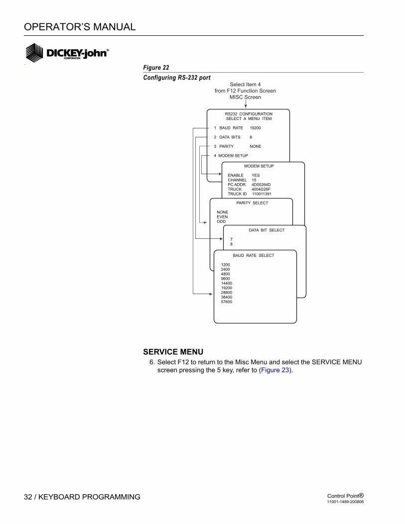
SERIAL PORT CONFIGURATION5. Select F12 to return to the Misc Menu and select Serial Port
Configuration (4). (Refer to Figure 22). This menu allows setting of the serial port for communicating with other devices. Values must match the serial data format of the other serial devices. The Esc key accepts the values instead of the Enter key. The pre-programmed values are appropriate for use with other DICKEY-john equipment and software.– Press 1 for the Baud Rate Select screen. Use the Up/Down arrow
keys to change the baud rate. Press Esc key when finished.– Press 2 for the Data Bit Select screen. Use the Up/Down arrow
keys to change the data bits to be used. Press Esc key when finished.
– Press 3 for the Parity Select screen. Use the Up/Down arrow keys to change the data bits to be used. Press Esc key when finished.
– Press 4 for Modem Setup screen (wireless users refer to CP Tools Software Manual for wireless communication hardware). Channel, PC address, Truck address and Truck ID are required entries for wireless transmission. Press Esc key when finished.
SYSTEM UNITS METRIC NOMILES NOMILES – FEET NOSQ. FEET NOSQ. YARD NO1,000 SQ. FEET YES
Select Item 3
from F12 Function Screen
(MISC Screen)
SYSTEM UNITS METRIC YESKILOMETERS YESKILOMETER-METER NOSQ. METER NOKG SQ. METER NO
English Metric
OPERATOR’S MANUAL
Control Point®11001-1489-200806
32 / KEYBOARD PROGRAMMING
Figure 22Configuring RS-232 port
SERVICE MENU6. Select F12 to return to the Misc Menu and select the SERVICE MENU
screen pressing the 5 key, refer to (Figure 23).
RS232 CONFIGURATION SELECT A MENU ITEM
1 BAUD RATE 19200
2 DATA BITS 8
3 PARITY NONE
4 MODEM SETUP
Select Item 4
from F12 Function Screen
MISC Screen
MODEM SETUP
ENABLE YESCHANNEL 15PC ADDR 4D00264DTRUCK 4004D26FTRUCK ID 110011391
PARITY SELECT
NONEEVENODD
DATA BIT SELECT
78
BAUD RATE SELECT
12002400480096001440019200288003840057600

OPERATOR’S MANUAL
Control Point®11001-1489-200806
KEYBOARD PROGRAMMING / 33
Figure 23Viewing the Service Menu Items
This menu is not intended for general customer use but for ice personnel to incorporate future product enhancements, troubleshooting, and to identify the currently installed software version.
– UPDATE SOFTWARE – Used by qualified personnel to install new software or updates.
– DISPLAY SOFTWARE VERSION – Displays the current installed software version.
– SYSTEM RESET – Can be used to return all parameters to factory setting. This is useful in starting over when the present settings
SERVICE MENU SELECT A MENU ITEM
1 UPDATE SOFTWARE
2 DISPLAY SOFTWARE VERSION
3 SYSTEM RESET
4 SYS RESPONS
5 CHANGE LANGUAGE/KEYBOARD
F12 Function Screen
(MISC Menu)
CHANGE LANGUAGE/KEYBOARD
FRENCH LANGUAGE NO FRENCH KEYBOARD NO
SYS RSPNS SELECT A MENU ITEM
1 GRANULAR
2 LIQUID PRE-WET
3 LIQUID ANTI-ICING
4 SPINNER
SYSTEM RESET
DO YOU REALLY WANTTO CLEAR ALL STOREDVALUES AND RETURN
TO FACTORY DEFAULTS?
ALL PROGRAMMEDVALUES WILL BE LOST
PRESS ENTER TOCONFIRM
• From Sub-Function screen,
select Parameter screen.
• View or proceed with caution.
SOFTWARE VERSION INFO
CONTROL POINT
DICKEY-JOHN CORPORATION5200 DICKEY-JOHN ROAD
AUBURN, IL 62615800-637-3302
SFTWRE VRSN VERSION X.XBUILT: 4 JUN XX 8:11 AM
SOFTWARE DOWNLOAD
DO YOU REALLY WANT
TO REPROGRAM MEMORY?
ENTER TO CONTINUE
ESC TO EXIT .
OPERATOR’S MANUAL
Control Point®11001-1489-200806
34 / KEYBOARD PROGRAMMING
become uncertain or confused. – SYS RESPONS – Displays System Response data which is useful
for troubleshooting. This screen can be viewed but not changed.– CHANGE LANGUAGE/KEYBOARD - Select a language and
keyboard from the screen. The system displays English and one other language, usually French Canadian. Contact DICKEY-john for available alternative languages. Select KEYBOARD from the screen. N (NO) selects an English keyboard, Y (YES) selects French.
OPERATOR’S MANUAL
Control Point®11001-1489-200806
KEYBOARD PROGRAMMING / 35
Figure 24Sensor Configuration Screen
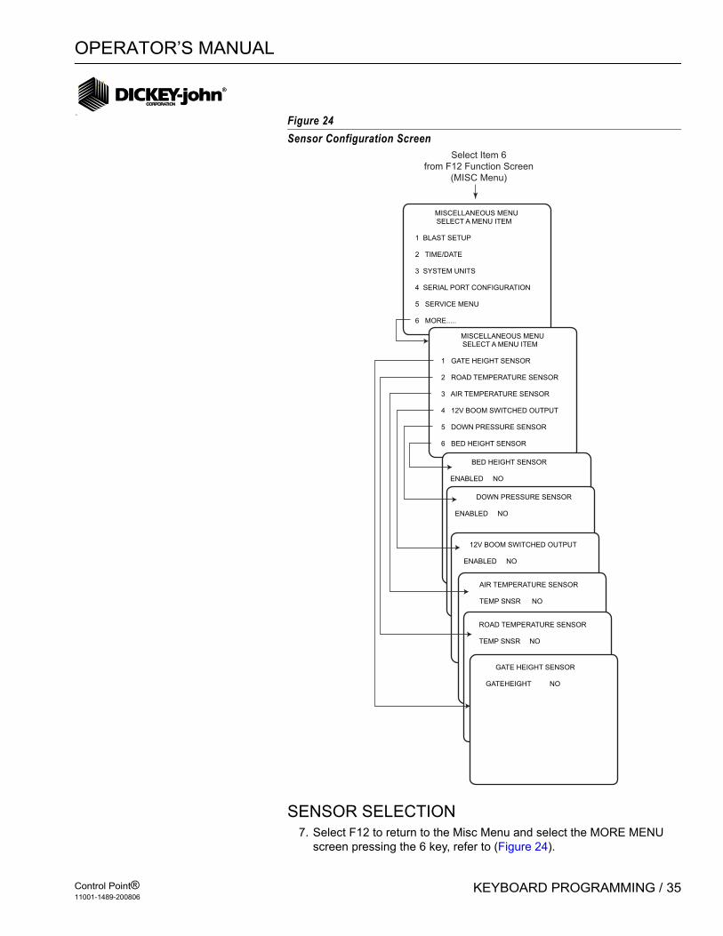
SENSOR SELECTION7. Select F12 to return to the Misc Menu and select the MORE MENU
screen pressing the 6 key, refer to (Figure 24).
MISCELLANEOUS MENU SELECT A MENU ITEM
1 BLAST SETUP
2 TIME/DATE
3 SYSTEM UNITS
4 SERIAL PORT CONFIGURATION
5 SERVICE MENU
6 MORE.....
MISCELLANEOUS MENU SELECT A MENU ITEM
1 GATE HEIGHT SENSOR
2 ROAD TEMPERATURE SENSOR
3 AIR TEMPERATURE SENSOR
4 12V BOOM SWITCHED OUTPUT
5 DOWN PRESSURE SENSOR
6 BED HEIGHT SENSOR
Select Item 6
from F12 Function Screen
(MISC Menu)
BED HEIGHT SENSOR
ENABLED NO
DOWN PRESSURE SENSOR
ENABLED NO
12V BOOM SWITCHED OUTPUT
ENABLED NO
AIR TEMPERATURE SENSOR
TEMP SNSR NO
ROAD TEMPERATURE SENSOR
TEMP SNSR NO
GATE HEIGHT SENSOR
GATEHEIGHT NO

OPERATOR’S MANUAL
Control Point®11001-1489-200806
36 / KEYBOARD PROGRAMMING
GATE HEIGHT SENSORThe Gate Height Sensor compensates for changes from the original calibrated gate setting by adjusting the conveyor speed allowing for a more accurate granular material application. If the gate height is increased, the conveyor speed will decrease and decreasing gate height will increase conveyor speed.
The Gate Height Sensor connects to the main harness lead labeled GATE on the current Control Point® harnesses and Pressure on the earlier harness versions. Software Versions 6.10 and higher have removed pressure control from the Control Point®. The software now utilizes the pressure sensor input for the Gate Height. Pressure-controlled liquid systems cannot use the 6.10 or higher version software.
When enabled, the Gate Height will display to the nearest .1 of an inch or 1 centimeter in the lower right corner of the Operate screen.
Figure 25Gate Height Screens
GATE HEIGHT CALIBRATIONThere are seven user-definable Gate Heights to enter that will aid in Gate Height calibration. Enter seven Gate Height settings that will be used when spreading material.
Calibration Steps:1. From the Gate Height Sensor screen, position the arrow at the Closed
position.2. Set the Gate to Closed.3. Measure the height at the Closed position and enter the Gate Height
value for the closed setting.4. Press C to capture the current gate height voltage at the closed
setting.5. Move the arrow to Setting 1.6. Set the Gate to the lowest operating Gate Height setting.7. Measure the height at Setting 1 and enter the Gate Height value for
Setting 1.8. Press C to capture the current Gate Height Voltage for Setting 1.9. Repeat 5-8 steps for the Settings 2-5 starting with the next lowest
setting.
GATE HEIGHT SENSOR
GATEHEIGHT NO
GATE HEIGHT SENSOR
GATEHEIGHT YESPOSITION IN VOLTCLOSED 1.0 0.0SETTING 1 2.0 1.0SETTING 2 3.0 2.0SETTING 3 4.0 2.9SETTING 4 5.0 3.9SETTING 5 6.0 4.4OPEN 9.0 5.0PRESS C CAL CURRENT VOLTPRESS D TO DELETEPRESS ESC WHEN DONE
No Gate Height Sensor Gate Height Sensor
OPERATOR’S MANUAL
Control Point®11001-1489-200806
KEYBOARD PROGRAMMING / 37
10. Move the cursor on the calibration screen to the Open setting.11. Set the Gate to the Full Open height.12. Measure the height at the Full open position and enter the Gate Height
for the Open setting.13. Press “C” to capture the current Gate Height voltage at the Open
setting.14. Press Esc when complete.
OPERATOR NOTES:If the sensor voltage is outside the range between the Closed and Open position values, the display will state Gate Low or Gate High. If Gate Low displays, the signal from the sensor is exceeding the open voltage. In either case, an alarm will activate. The Gate Height should be checked and set at the granular calibration it was ran for on that granular channel.
If the Gate Height is enabled and has been calibrated, all of the desired granular materials that are enabled must be re-calibrated through a material drop test. Refer to Calibrating Granular Materials section. If enabled materials are not calibrated, the Control Point® will alarm.
ROAD TEMPERATURE SENSORSelect F12 to return to the Misc Menu and select the MORE MENU screen pressing the 2 key.
The Road Temperature Sensor monitors road temperature changes. Three temperature alarm settings can be programmed.
The Road Temperature sensor connects to the Temperature Sensor Adapter (466492000S1) or Adapter (46649210051) which is connected to the main harness lead labeled Temperature.
For earlier versions of Control Point® harnesses, the adapter connects to the mating connector in the adapter harness (466492040S1).
When enabled, the road temperature displays in the lower left side of the Operate screen.
CONFIGURATIONRoad Temperature default is set for no temperature sensors. To change configurations, press Y (Yes) or N (No).

OPERATOR’S MANUAL
Control Point®11001-1489-200806
38 / KEYBOARD PROGRAMMING
Figure 26Road Temperature Screens
Alarm Temp 1-3There are three user-definable temperature alarms to alert of road temperature changes and that application rate or material changes may be required. The temperatures must be entered in descending order with Alarm Temp 1 the highest setting and Alarm Temp 3 the lowest setting.
Temp Hyst+Temperature Hysteresis indicates the positive temperature changes that has to occur above the active alarm temperature to clear the alarm. If Alarm Temp 1 is 20 degrees F and the Temp Hyst+ is 5 degrees F, the alarm activates when the temperature drops below 20 degrees F but clears when the temperature reaches 25 degrees F.
High & Low CalHigh & Low Cal values are created from the calibration routine and are for reference only and cannot be edited.
NOTE: Road Watch™ is a registered trademark of Commercial Vehicle Group™. Surface Patrol technology is a registered trademark of Control Products, Inc.
TEMPERATURE SENSOR CALIBRATIONPress C to start the Temperature Sensor Adapter automatic calibration procedure. Calibration lasts approximately 10 -20 seconds. Calibration is complete when the Road Temperature Sensor menu displays.
IMPORTANT: The RoadWatch™ temperature sensor or Surface Patrol™ temperature sensor must be disconnected and the Temperature Sensor Adapter connected to the main harness for successful calibration. If the Temperature Sensor Adapter is disconnected when calibration is performed, an error screen will display.
ROAD TEMPERATURE SENSOR
TEMP SNSR NO
ROAD TEMPERATURE SENSOR
TEMP SNSR YESALRM TEMP1 32.0 FALRM TEMP2 20.0 FALRM TEMP3 10.0 FTEMP HYST+ 5.0 FHIGH CAL 2.7 VOLTLOW CAL 0.76 VOLT
PRESS C TO CALIBRATE
No Temperature Sensor Road Temperature Sensor

OPERATOR’S MANUAL
Control Point®11001-1489-200806
KEYBOARD PROGRAMMING / 39
AIR TEMPERATURE SENSORSelect F12 to return to the Misc Menu and select the MORE MENU screen pressing the 3 key.
The Air Temperature Sensor monitors air temperature changes. Three temperature alarm settings can be programmed. The Air Temperature Sensor connects to the Temperature Sensor Adapter (466492100S1). The Temperature Sensor Adapter connects to the main harness on the lead labeled Temperature. For earlier versions of Control Point® harnesses, the adapter connects to the mating connector in the adapter harness (466492040S1).
When enabled, the Air Temperature will replace the date in the lower left side of the Operate screen.
CONFIGURATIONAir Temperature default is set for no temperature sensors. To change configurations, press Y (Yes) or N (No).
Figure 27Air Temperature Sensor Screens
Alarm Temp 1-3There are three user-definable temperature alarms to alert of air temperature changes and that application rate or material changes may be required. The temperatures must be entered in descending order with Alarm Temp 1 the highest setting and Alarm Temp 3 the lowest setting.
Temp Hyst+Temperature Hysteresis indicates the positive temperature changes that has to occur above the active alarm temperature to clear the alarm. If Alarm Temp 1 is 20 degrees F and the Temp Hyst+ is 5 degrees F, the alarm activates when the temperature drops below 20 degree F but clears when the temperature reaches 25 degrees F.
High & Low CalHigh & Low Cal values are created from the calibration routine and are for reference only. These values cannot be altered.
AIR TEMPERATURE SENSOR
TEMP SNSR NO
AIR TEMPERATURE SENSOR
TEMP SNSR YESALRM TEMP1 32.0 FALRM TEMP2 20.0 FALRM TEMP3 10.0 FTEMP HYST+ 5.0 FHIGH CAL 2.7 VOLTLOW CAL 0.76 VOLT
PRESS C TO CALIBRATE
No Temperature Sensor Air Temperature Sensor

OPERATOR’S MANUAL
Control Point®11001-1489-200806
40 / KEYBOARD PROGRAMMING
AIR TEMPERATURE SENSOR CALIBRATIONPress C to start the Temperature Sensor Adapter automatic calibration procedure. Calibration lasts approximately 10-20 seconds. Calibration is complete when the Air Temperature Sensor menu displays.
IMPORTANT: The RoadWatch™ temperature sensor or Surface Patrol™ temperature sensor must be disconnected and the Temperature Sensor Adapter connected to the main harness for successful calibration. If the Temperature Sensor Adapter is disconnected when calibration is performed, an error screen will display.

OPERATOR’S MANUAL
Control Point®11001-1489-200806
KEYBOARD PROGRAMMING / 41
12V BOOM SWITCHED OUTPUTSelect F12 to return to the Misc Menu and select the MORE MENU screen pressing the 4 key.
The 12 Volt Switched Output provides a 12V output signal for a valve driver to control a boom shut off relay. The default value for Switched Output is NO. Connect the valve driver to the main harness lead labeled Switched +12V. For earlier versions of Control Point® harnesses, connect the valve driver using the adapter harness (466492040S1) connecting the switched 12V drive signal to pin 9 of the 16 pin granular valve connector.
Figure 2812V Boom Switched Output Screens
The 12V Boom Switched Output functionality varies for different versions of the hardware console.
To Verify Software Version:Press Miscellaneous (F12), Service Menu (5), Display Software Version (2).
Any consoles with no hardware version number indicated or the version is found in a different location than described above is also a Version 1 software.
Hardware Version 1 consoles require the following conditions for the 12V Boom Switched Output to function correctly:
– All granular channels disabled.– If Boom 5 is configured to utilize an anti-ice/pre-wet switch, the
switch must be in anti-ice mode.– Anti-ice only mode.
Hardware Version 2 consoles require a liquid channel to be enabled for the 12 Boom Switched output to function correctly.
12V BOOM SWITCHED OUTPUT
ENABLED NO
No Boom Switched Output Boom Switched Output
12V BOOM SWITCHED OUTPUT
ENABLED YES

OPERATOR’S MANUAL
Control Point®11001-1489-200806
42 / KEYBOARD PROGRAMMING
Once the above conditions have been met and the Control Point® initiates liquid application, the 12V output will be turned on. There will be no visual indication from the Operator screen that this feature is enabled or active. The 12V switched output is not a high-current line so to control a solenoid valve, a power driver is required. The output will then activate the valve driver to control the valve.
Contact DICKEY-john for information on the driver and the adapter harness.
DOWN PRESSURE SENSORThe Down Pressure Sensor monitors the relative pressure applied to the under body belly scraper. The sensor uses the same input as the Tank Level Sensor.
Connect the Down Pressure Sensor to the main harness lead labeled Tank or use an adapter harness (466492040S1) for earlier Control Point® harness versions to connect the Down Pressure sensor signal to pin 13 of the 16-pin granular valve connector.
The Down Pressure sensor feature must be enabled in the Console to become active. When enabled, a bar graph with a digital percentage readout representing the down pressure displays. When the Down Pressure sensor is enabled, the tank level is automatically disabled. If granular is enabled, the spinner bar graph and the down pressure bar graph share its portion of the Operate screen.
NOTE: The Tank Level Sensor and the Down Pressure Sensor cannot be configured or used at the same time.
Figure 29Down Pressure Sensor Screens
CONFIGURATIONThe initial down pressure screen has a Yes or No option for sensor configuration. Down Pressure Sensor default is NO. Refer to (Figure 29) for Enabled and Disabled Down Pressure Sensor screens.
DOWN PRESSURE SENSOR CALIBRATIONMinimum and maximum pressures can be entered manually or automatically captured. The minimum pressure sensor indicates minimum pressure allowed when the underbody scraper is off the pavement. The maximum pressure sensor indicates the maximum pressure allowed with the scraper completely down.
DOWN PRESURE SENSOR
ENABLED NO
DOWN PRESSURE SENSOR
ENABLED YESMIN PRESS 0.2 VOLTMAX PRESS 5.0 VOLTDOWN ALARM 5 %
SELECT POSITION THENPRESS C TO CALIBRATE CURRENT VOLTAGEPRESS D OR ESC WHEN DONE
Down Pressure
Sensor Disabled Down Pressure
Sensor Enabled

OPERATOR’S MANUAL
Control Point®11001-1489-200806
KEYBOARD PROGRAMMING / 43
For Manual Entry - Select the Min Press text and enter the minimum pressure voltage from the pressure sensors manufacturer’s specifications.
For Automatic Entry - The belly scraper MUST be off the ground and the sensor installed prior to automatic entry. Select the Min Press text and press “C” to capture sensor voltage.
Down Alarm is a user-definable percentage value of the maximum pressure. An alarm activates when the pressure exceed the alarm limit.
BED HEIGHT SENSORThe Bed Height sensors activates when the bed has exceeded the recommended operating height.
The operator must inspect and maintain all mechanical linkage of the sensor on a regularly scheduled interval to insure proper operation of the bed height alarm. Visual inspection of the bed height must be maintained as the primary indicator of safe bed height operation. The alarm should only be used as a secondary convenience indicator. The operator assumes all risk in using this feature. DICKEY-john assumes no responsibility for alarm failure to indicate an unsafe operating height.
BED HEIGHT SENSOR CONNECTIONCurrent Versions: Connect the Gate input on the current version main harnesses.
Earlier Versions: Connect the Bed Height sensor to the Pressure input on earlier versions of Control Point® main harnesses.
If the Gate Height is configured and the Bed Height sensor is enabled, the Gate Height sensor automatically is disabled. The Bed Height sensor feature must be enabled in the Control Point® console for activation.
Bed Height Sensor Activation: (F12) Misc, (6) More, (6) Bed Height Sensor
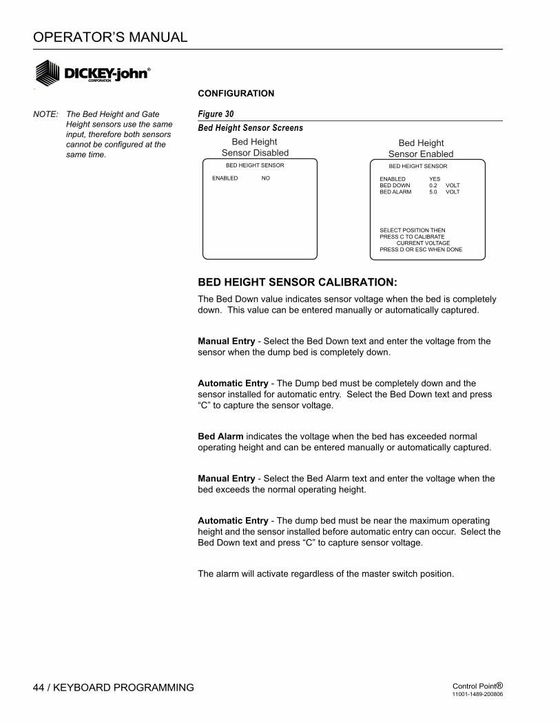
OPERATOR’S MANUAL
Control Point®11001-1489-200806
44 / KEYBOARD PROGRAMMING
CONFIGURATION
NOTE: The Bed Height and Gate Height sensors use the same input, therefore both sensors cannot be configured at the same time.
Figure 30Bed Height Sensor Screens
BED HEIGHT SENSOR CALIBRATION:The Bed Down value indicates sensor voltage when the bed is completely down. This value can be entered manually or automatically captured.
Manual Entry - Select the Bed Down text and enter the voltage from the sensor when the dump bed is completely down.
Automatic Entry - The Dump bed must be completely down and the sensor installed for automatic entry. Select the Bed Down text and press “C” to capture the sensor voltage.
Bed Alarm indicates the voltage when the bed has exceeded normal operating height and can be entered manually or automatically captured.
Manual Entry - Select the Bed Alarm text and enter the voltage when the bed exceeds the normal operating height.
Automatic Entry - The dump bed must be near the maximum operating height and the sensor installed before automatic entry can occur. Select the Bed Down text and press “C” to capture sensor voltage.
The alarm will activate regardless of the master switch position.
BED HEIGHT SENSOR
ENABLED NO
BED HEIGHT SENSOR
ENABLED YESBED DOWN 0.2 VOLTBED ALARM 5.0 VOLT
SELECT POSITION THENPRESS C TO CALIBRATE CURRENT VOLTAGEPRESS D OR ESC WHEN DONE
Bed Height
Sensor Disabled Bed Height
Sensor Enabled

OPERATOR’S MANUAL
Control Point®11001-1489-200806
KEYBOARD PROGRAMMING / 45
ACCESSING THE OPERATE MODE (F1)F1 accesses the Operate screens anytime during programming to verify selections. No programming parameters are available from this screen. The following information is a brief outline of the Operate mode screens. For full details, see the Startup & Familiarization section.
OPERATE screen – Shows programmed values ready for spreading product in a normal fashion with keyboard connected.
MATERIAL/MANUAL SPEED SELECT screen – A dual screen showing only items configured. The MATERIAL SELECT half displays if more than one granular and/or liquid products are enabled in the Granular (F2) and Liquid (F4) Application Rate functions. The MANUAL SPEED SELECT appears if MANUAL DRIVER is programmed YES in the Ground Speed Configuration function (F7, selection 1).
CURRENT TOTALS screen – Shows totals accumulated for each product dispensed since the last reset (See Accumulator Function - F9). These totals are those products selected on the Material/Manual Speed Select Screen. To see other totals, select those products from that screen.
SEASON TOTALS screen – Shows the amount of material applied, miles traveled during application, and hours elapsed this season for each product in both the AUTO and BLAST modes. The season totals can only be cleared from the Accumulator function (F9).
SETTING UP GRANULAR CONFIGURATION (F3)Configuration parameters specify types of hydraulic valves and sensors used and related performance specifications. To prepare for system calibration, the granular configuration parameters for each granular material used must be verified or programmed. These parameters do not change unless system hardware changes or related calibration routines are rerun.
1. From the keyboard, press Function key F3 to obtain the GRANULAR CONFIG screen (refer to Figure 28). Four (4) granular product names appear with each followed by the word ENABLED or DISABLED. Products are enabled/disabled from the GRANULAR APPL RATE (F2) screen.
2. Select a material using the corresponding number key. 3. Edit the parameters on the screen.

OPERATOR’S MANUAL
Control Point®11001-1489-200806
46 / KEYBOARD PROGRAMMING
Figure 31Configuring the Granular Channel
Check each following item for a desired setting.
– SPR CON (Spreader Constant) – Represents the number of pulses generated by the application rate sensor per pound of material (P/LB) discharged from the spreader.The spreader constant differs for each granular material, spreader vehicle, and gate height setting. If the spreader constant is known, keyboard enter the value so that running the GRANULAR CALIBRATION routine for this material is unnecessary. If the spreader constant is unknown, leave the displayed value. The correct value is automatically corrected later, during GRANULAR CALIBRATION.
– CAL GT HGT (Calibration Gate Height) - Displayed only if optional Gate Height Sensor is Enabled. If Enabled, the Calibration Gate Height valve displayed is the setting of the gate height in inches when the spreader was calibrated. Refer to page 77 for the Spreader Calibration procedure.Changing the original calibrated gate setting by adjusting the conveyor speed provides a more accurate granular material application. Increased Gate Height decreases conveyor speed; Decreased Gate Height increases conveyor speed.
– DRV FREQ (Drive Frequency) – Represents the valve manufacturer’s suggested drive frequency, as shown on the valve specification sheet.
CONFIGURATION SELECT A MENU ITEM
1 SALT ENABLED
2 SAND DISABLED
3 MIX A DISABLED
4 MIX B DISABLED
Press Function Key F3
(GRANULAR CONFIG)
SALT CONFIGURATION
SPR CON 80.0 P/LBCAL GT HGT 7.4 INDRV FREQ 100 HZPWM OFFSET 14PWM SAT 70SYS RSPNS 11.25VALV BOOST 2.0AFILT 0.250000

OPERATOR’S MANUAL
Control Point®11001-1489-200806
KEYBOARD PROGRAMMING / 47
The following configuration constants (PWM OFFSET, PWM SAT, SYS RSPNS, VALV BOOST, and AFILT) are for descriptive purposes only. The correct parameters automatically calculate during GRANULAR SYSTEM RESPONSE calibration. Factory defaults are adequate until calibration is run. These values can be adjusted any time to fine tune system performance.
– PWM OFFSET – Identifies the minimum amount of PWM valve drive required to start the granular mechanism moving.
– PWM SAT (PWM Saturation) – Identifies the amount of drive the granular valve system requires to operate a PWM valve at full speed. This value is not displayed when SRVO DRV is set to YES.
– SYS RSPNS (System Response) – Adjusts the control system response time to the hydraulic and mechanical systems of the granular control channel on each particular spreader vehicle.
– VALV BOOST (Valve Boost)– Increases the amount of system response initially applied to the granular control to reach final operating speed as quickly as possible.
– AFILT (A Filter) – Filters the feedback signal to minimize effects of electrical noise and mechanical vibrations. The smaller the number the greater degree of filtering.
4. Press F3 to return to the GRANULAR CONFIG screen.5. If using other granular materials with known SPR CON (spreader
constant), enter those values now.
Note: The system has only one granular control channel, so only one configuration parameter (PWM hydraulic valve) is used. All four materials remain the same except for the SPR CON.
OPERATOR’S MANUAL
Control Point®11001-1489-200806
48 / KEYBOARD PROGRAMMING
PROGRAMMING GRANULAR APPLICATION RATES (F2)The APPLICATION RATE menu lists four granular materials. Each material screen contains a set of values for product application rate, APR steps, min/max limits, and blast rate. The pre-programmed values are usually the same for all granular materials but may be edited and modified as required.
1. From the keyboard, press Function key F2 to obtain the GRANULAR APPLICATION RATES screen, refer to (Figure 32). Four (4) granular product names appear, each followed by the word ENABLED or DISABLED.
2. Select a material using the corresponding number key. 3. Edit the parameters on the screen.
Check each following item for the desired setting.
– ENABLE - When enabled, the material appears on the MATERIAL/MANUAL SPEED SELECT screen of the Operate mode for selecting. Enter Y for YES (enabled), N for NO (disabled). At least one granular material must be enabled unless console is used for anti-icing, then all granulars can be disabled. All products can be programmed (and calibrated) now and selected from the Operate mode later.
– STEP METHD - Y (YES) selects the Step method or N (NO) the Rate method to specify application rates (APRs). Since each method performs essentially the same function, the choice becomes a personal preference. However, the parameters for each method are different and all items below change with the selection (See Figure 33 for Rate Method screens).
Changing from one APR method to the other for any material automatically clears all previous rates from that method.
The STEP method permits the APR to be changed by a fixed increment using the “+/–” switch on the Switch Module. The RATE method allows programming of up to ten (10) different APRs - RATE 1 through RATE 10. If less than ten rates are chosen, enter a zero (0) for each rate following the last one programmed. The initial rate displayed in the OPERATE mode is RATE 1. Other rates are selected by pressing the “+/–” switch on the Switch Module.

OPERATOR’S MANUAL
Control Point®11001-1489-200806
KEYBOARD PROGRAMMING / 49
Figure 32Setting Granular Application Rates (Step Method)
– APP START (Step method) – Defines the APR starting point. – IC/DC STP (Step method) - Sets the increase/decrease step value.– MIN APP (Step method) – Defines the minimum APR limit for the
product.– MAX APP (Step method) – Defines the maximum APR limit for the
product.– RATE 1 through RATE 10 (Rate method) – Defines up to ten
individual APR rates.– BLAST RATE (Step or Rate method) – Defines a higher than
normal, spot-application rate applied when the red BLAST button is pressed.
– CHNL LBL (Channel Label) (Step or Rate method) – Any product material name of up to nine (9) characters can be keyed in. Pressing the ENTER key stores the name for display on all granular screens including the OPERATE screen wherever that material appears in the event there is a data download.
4. Press F2 to return to the GRANULAR APPL RATE screen. If other granular materials require programming, repeat the above procedures for those materials.
APPLICATION RATE SELECT A MENU ITEM
1 SALT ENABLED
2 SAND DISABLED
3 MIX A DISABLED
4 MIX B DISABLED
Press Function Key F2
(GRANULAR APPL RATE)
SALT APP RATES
ENABLE YESSTEP METHD YESAPP START 500.0 LBS / MILEIC / DC STP 100.0 LBS / MILEMIN APP 0.0 LBS / MILEMAX APP 1200 LBS / MILEBLST RATE 1200 LBS / MILECHNL LBL SALT
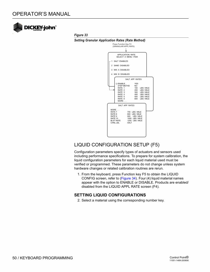
OPERATOR’S MANUAL
Control Point®11001-1489-200806
50 / KEYBOARD PROGRAMMING
Figure 33Setting Granular Application Rates (Rate Method)
LIQUID CONFIGURATION SETUP (F5)Configuration parameters specify types of actuators and sensors used including performance specifications. To prepare for system calibration, the liquid configuration parameters for each liquid material used must be verified or programmed. These parameters do not change unless system hardware changes or related calibration routines are rerun.
1. From the keyboard, press Function key F5 to obtain the LIQUID CONFIG screen, refer to (Figure 34). Four (4) liquid material names appear with the option to ENABLE or DISABLE. Products are enabled/disabled from the LIQUID APPL RATE screen (F4).
SETTING LIQUID CONFIGURATIONS2. Select a material using the corresponding number key.
APPLICATION RATE SELECT A MENU ITEM
1 SALT ENABLED
2 SAND DISABLED
3 MIX A DISABLED
4 MIX B DISABLED
Press Function Key F2
(GRANULAR APPL RATE)
SALT APP RATES
ENABLE YESSTEP METHD NORATE 1 100 LBS / MILERATE 2 200 LBS / MILERATE 3 300 LBS / MILERATE 4 400 LBS / MILERATE 5 500 LBS / MILERATE 6 600 LBS / MILEMORE . . .
SALT APP RATES
MORE . . .RATE 7 700 LBS / MILERATE 8 800 LBS / MILERATE 9 900 LBS / MILERATE 10 1000 LBS / MILEBLST RATE 1200 LBS / MILECHNL LBL SALT

OPERATOR’S MANUAL
Control Point®11001-1489-200806
KEYBOARD PROGRAMMING / 51
Figure 34Liquid Configuration Main Screen
3. Edit the parameters on the screen for the desired setting.– PRE WET - If spraying with the pre-wet spray bar, press Y (YES). If
used with the anti-icing boom, press N (NO).– K-FACTOR (Flowmeter Constant) - Represents the number of
flowmeter pulses generated per gallon (P/GAL) of dispersed liquid (for pre-wet and anti-icing liquids). The K-FACTOR number stamped on the flowmeter body is sufficiently accurate for keyboard entry if the viscosity of the liquid is near that of water.
If the flowmeter constant is unknown, leave the displayed default value shown. A corrected value automatically calculates and enters during LIQUID CALIBRATION.
– SRVO DRV (Servo/Proportional) - If using a servo drive, press Y (YES). For a proportional valve, select N (NO).
– DRV FREQ (Drive Frequency) - Represents the valve manufacturer’s suggested drive frequency, as shown on the valve specification sheet.
– PWM OFFSET - Represents the valve operating range starting point (position flowmeter begins generating pulses). This constant
CONFIGURATION SELECT A MENU ITEM
1 PREWET ENABLED
2 DEICING ENABLED
3 LIQUID 3 DISABLED
4 LIQUID 4 DISABLED
5 BOOM
Press Function Key F5
(LIQUID CONFIG)
-First four products show identicalparameter screens.
-PWM SAT only present for proportional valve.
PREWET CONFIGURATION
PRE WET YESK - FACTOR 10000.0 P/GALSRVO DRV YESDRV FREQ 100 HZPWM OFFSET 0PWM SAT 64SYS RSPNS 2.500000VALV BOOST 2.0MORE...
PREWET CONFIGURATION
MORE...AFILT 0.077000TANK LEVEL YESVALVE LOCK NO
PRESS C TO CAL TANK LEVEL
Appears when Tank Level
set to YES
OPERATOR’S MANUAL
Control Point®11001-1489-200806
52 / KEYBOARD PROGRAMMING
automatically calculates and enters during a LIQUID SYSTEM RESPONSE routine (F11-2 and F11-3) or can be keyboard entered. Anti-icing boom liquids may have a different offset constant than pre-wet bar liquids because of different plumbing components.
– PWM SAT (Proportional valve only) - Represents the end point of the valve operating range (maximum flowmeter pulse frequency). The value calculates automatically during the LIQUID SYSTEM RESPONSE routines or can be keyboard entered. Liquids dispensed from the anti-icing boom may have different constants than those from the pre-wet bar because of different plumbing components.
– SYS RSPNS (System Response) - Adjusts the control system response time to the hydraulic and mechanical systems of the liquid control channel for each particular spreader vehicle. The value calculates automatically during calibration routines but can be fine-tuned anytime for optimum performance by keyboard entry.
– VALV BOOST (Valve Boost) - Increases the amount of system response initially applied to reach final operating speed as quickly as possible.
– AFILT (A Filter) - Filters the feedback signal to minimize effects of electrical noise and mechanical vibrations. The smaller the number the greater degree of filtering.
– TANK LEVEL SENSOR - Monitors the liquid level for the pre-wet or anti-ice systems.
– VALVE LOCK - When Valve Lock is set to Yes, the valve is locked in the last operating position when only the boom sections are turned off and the master switch is left on. Valve Locking maintains constant pressure so a quick spray pattern can resume when the boom solenoids are turned back on.
4. Press F5 to return to the LIQUID CONFIGURATION screen. If other liquid materials require programming, repeat the above procedures for those materials. All pre-wet liquids should be programmed first to avoid confusion.
TANK LEVEL SENSOR CONFIGURATION5. The Tank Level Sensor monitors the liquid level for pre-wet or anti-ice
systems.The sensor connects to the main harness with the lead labeled Tank or to an adapter harness (466492040) that ties the tank level signal to pin 13 of the 16-pin granular valve connector on earlier versions of Control Point® main harnesses. The tank level sensor feature must be enabled in the Control Point® console before it is activated. It can be enabled for one of the four liquid materials.The tank level will display only when enabled and the selected material that it was enabled under is active. (If liquid 1 is set for prewet (Yes) with tank level enabled and liquid 2 is anti-ice (prewet No), the tank level will only display when liquid 1 prewet is active.
If the Control Point® has been configured for use with anti-ice/prewet switch input on Boom 5 to automatically switch between liquid 1 preset
OPERATOR’S MANUAL
Control Point®11001-1489-200806
KEYBOARD PROGRAMMING / 53
and liquid 2 anti-ice, the tank level will only display when the switch is in prewet mode. If the switch is in anti-ice mode, the tank level will not display.
If the tank level is set for liquid 2, enable tank level under the liquid 2 configuration screen. This will disable the tank level on liquid 1. When the tank level is enabled, a bar graph with a digital percentage readout (bargraph YES) or an approximate material remaining readout will display (bargraph NO). If granular is enabled, the spinner bar graph will share its portion of the Operate screen with the tank level. If the tank level is disabled, the spinner bar graph will display across the lower section of the Operate screen.
ENABLING TANK LEVEL SENSOR6. Press Function key F5 Liquid Configuration and select a material 1-4.
The default for Tank Level is NO. When Tank Level is changed to YES, the text PRESS C TO CAL TANK LEVEL appears at the bottom of the screen. Press C to begin calibration. When complete, press D or Escape key (refer to Figure 35).
TANK EMPTY AND TANK FULL Both the Tank Empty and Tank Full values can be entered manually or automatically captured.
Manual Entry: Select the Tank Empty text and enter the empty voltage from the manufacturer’s specifications.
Automatic Entry: Verify the tank is empty and the sensor is installed and connected. Select the Tank Empty text and Press “C” to capture the sensor voltage.
TANK ALARMThe Tank Alarm is a user-definable value that informs the driver when the tank level has reached the alarm limit. The value has a 5% hysteresis tolerance to prevent random alarming due to varying tank levels while driving.
Example 1: If the Tank Alarm is set for 10%, the alarm will activate when the level drops below 10%, but will not be cleared until the level reaches 15%).
Example 2: If the Tank Alarm is set for 100 gallons on a 1000 gallon capacity, the alarm will activate when the level drops below 100 gallons, but will not be cleared until the level reaches 150 gallons).
The alarm will sound for the first five seconds, then the text will flash on the screen until the condition is cleared or another alarm is issued.

OPERATOR’S MANUAL
Control Point®11001-1489-200806
54 / KEYBOARD PROGRAMMING
TANK CAPACITYTank Capacity indicates the maximum holding capacity of the tank. The alarm is only active when the master switch is in the AUTO position. The alarm will activate audible and visual signals when the tank level drops below the Tank Alarm. When the master switch is turned OFF and then returns to AUTO, the alarm will not be re-issued until the level goes above the Tank Alarm plus the 5% hysteresis or until the unit has been turned off.
Figure 35Tank Level Calibration Screen
TANK LEVEL CALIBRATION
BARGRAPH YESTANK EMPTY 0.2 VOLTTANK FULL 5.0 VOLTTANK ALARM 5
SELECT POSITION THENPRESS C TO CALIBRATE CURRENT VOLTAGEPRESS D OR ESC WHEN DONE
TANK LEVEL CALIBRATION
BARGRAPH NOTANK EMPTY 0.2 VOLTTANK FULL 5.0 VOLTTANK ALARM 25.0 GALCAPACITY 500.0 GAL
SELECT POSITION THENPRESS C TO CALIBRATE CURRENT VOLTAGEPRESS D OR ESC WHEN DONE
Bar Graph No Bar Graph

OPERATOR’S MANUAL
Control Point®11001-1489-200806
KEYBOARD PROGRAMMING / 55
BOOM CONFIGURATION7. Press the F5 Function Key to return to Liquid Configuration screen.
Select the 5 key to display the Boom Configuration screen.
Figure 36Liquid Channel Boom Sections Configuration
8. Select a Boom Section and press a number key for the desired SECTION CONFIGURATION screen (refer to Figure 36).
CONFIGURATION SELECT A MENU ITEM
1 LIQUID 1 ENABLED
2 LIQUID 2 DISABLED
3 LIQUID 3 DISABLED
4 LIQUID 4 DISABLED
5 BOOM
Press Function Key F5
(LIQUID CONFIG)
BOOM CONFIGURATION SELECT A MENU ITEM
1 SECTION 1
2 SECTION 2
3 SECTION 3
4 SECTION 4/PAUSE
5 SECTION 5 / AUTO ANTI-ICING
SECTION 1 CONFIGURATION
SECTN ENBLED YES 12V ON NO NUM OF NZZLS 1 NZZLE SPCNG 36.0 IN BOOM INPUT YES
SECTION 4 CONFIGURATION
SECTN ENBLED YES 12V ON NO BOOM INPUT NO PAUSE ENABLE NO
• Section 5 adds BOOM INPUT
selection.
SECTION 5 CONFIGURATION
12V ON NO BOOM INPUT NO

OPERATOR’S MANUAL
Control Point®11001-1489-200806
56 / KEYBOARD PROGRAMMING
The parameters for this screen are as follows:
Section 1-4– SECTN ENBLED (Section Enabled) - Enter Y (YES) to enable the
boom section, N (NO) to disable.– 12V On - Entering Y (YES) indicates +12 volts activates the section
solenoid. N(NO) means grounding activates the section solenoid.– NUM OF NZZLS (Number of Nozzles) - Enter the number of
nozzles in the boom section.– NZZLE SPCNG (Nozzle Spacing) - Enter the distance between
nozzles.
Section 4/Pause– BOOM INPUT- This parameter only appears for Section 4. Entering
N (NO) activates Pause Enable that senses the position of an optional add-on Pause Switch and its position.
– PAUSE ENABLE - The Pause switch will turn the material application ON and OFF. Enter Y (YES) when using a customer-supplied Pause Switch used to turn the material application ON and OFF. Each time the pause switch shuts on and off, an event occurs that tracks mileage with on/off time in the On/Off History (F10) screen and is downloaded in the full spread report.
NOTE: Boom Input and Pause Enable cannot both be set to Yes.
Section 5/Auto Anti-IcingIf the boom has been enabled to sense the position of a Pre-wet/Anti-ice Switch, the Liquid channel (while in the OPERATE mode) automatically switches between Liquid 1 (Pre-Wet) and Liquid 2 (Anti-ice) to avoid having to use the Material Select Screen to make the change.
To use the Pre-wet/Anti-icing auto switch input feature, SECTION 5/AUTO ANTI-ICING configuration must be set as follows:–12V ON NO–Boom Input NO
To use Section 5 for monitoring section 5 of a 5 section sprayer bar, set as follows:
–Boom Input YES
Prewet/Anti-icing Switch and the Monitor Sprayer Section 5 cannot be utilized simultaneously.

OPERATOR’S MANUAL
Control Point®11001-1489-200806
KEYBOARD PROGRAMMING / 57
PROGRAMMING LIQUID APPLICATION RATES (F4)The Application Rate screens list four liquid materials. Each material screen contains a set of values for product application rate, APR steps, min/max limits, and blast rate. The pre-programmed values for these parameters are usually the same for all liquid pre-wet materials and the same for all liquid anti-icing materials. Each screen should be edited and modified as required. Note: F5 should be used to select between liquids, pre-wet and anti-ice before proceeding.
1. From the keyboard, press F4 to obtain the Liquid Application Rates screen, refer to (Figure 37). Four (4) liquid product names are shown, each followed by the word ENABLED or DISABLED.
2. Select a material using the corresponding number key. 3. Edit the parameters on the selected screen. Check each following item
for desired settings.
NOTE: The Material Selection screen has been updated to limit the display of prewet and anti-ice materials to only the active type when the Boom 5 input is configured for prewet/anti-ice selection. For example, if materials 1 and 2 are prewet and 3 and 4 are anti-ice with the Boom 5 switch in the prewet mode, only materials 1 and 2 will appear. Changing the switch to anti-ice at the operate screen, only materials 3 and 4 will display.
– ENABLE - When enabled, the material appears on the Material/Manual Speed Select screen in the Operate mode to allow selecting for use. Enter Y for YES (enabled), N for No (disabled).
At least one liquid product must be enabled. If the controller is granular only, all liquids can be disabled. All products can be programmed (and calibrated) now and enabled later.
– STEP METHD - Y (Yes) selects the Step Method or N (No) the Rate method to specify application rates (APRs). The parameters for each method are different and all items below change with the selection (Refer to Figure 33 for Rate Method screen).
Changing from one APR Method to the other for any material automatically clears all previous rates from that method.
The STEP Method permits the APR to be changed by a fixed increment using the “+/–” switch on the Switch Module. The Rate method allows programming of up to ten (10) different APRs - Rate 1 through Rate 10. If less than ten rates are chosen, enter a zero (0) for each rate following the last one programmed. The initial rate displayed in the Operate mode is Rate 1. Other rates are selected by pressing the “+/–” switch on the Switch Module.
– APP START (Step Method) – Defines the start-point APR. – IC/DC STP (Step Method) - Sets the increase/decrease step value.– MIN APP (Step Method) – Defines the minimum APR limit for the
product.
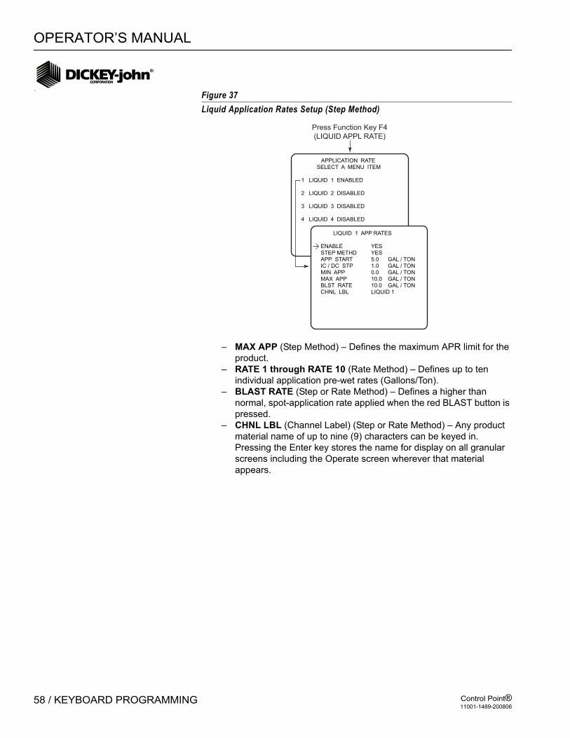
OPERATOR’S MANUAL
Control Point®11001-1489-200806
58 / KEYBOARD PROGRAMMING
Figure 37Liquid Application Rates Setup (Step Method)
– MAX APP (Step Method) – Defines the maximum APR limit for the product.
– RATE 1 through RATE 10 (Rate Method) – Defines up to ten individual application pre-wet rates (Gallons/Ton).
– BLAST RATE (Step or Rate Method) – Defines a higher than normal, spot-application rate applied when the red BLAST button is pressed.
– CHNL LBL (Channel Label) (Step or Rate Method) – Any product material name of up to nine (9) characters can be keyed in. Pressing the Enter key stores the name for display on all granular screens including the Operate screen wherever that material appears.
APPLICATION RATE SELECT A MENU ITEM
1 LIQUID 1 ENABLED
2 LIQUID 2 DISABLED
3 LIQUID 3 DISABLED
4 LIQUID 4 DISABLED
LIQUID 1 APP RATES
ENABLE YESSTEP METHD YESAPP START 5.0 GAL / TONIC / DC STP 1.0 GAL / TONMIN APP 0.0 GAL / TONMAX APP 10.0 GAL / TONBLST RATE 10.0 GAL / TONCHNL LBL LIQUID 1
Press Function Key F4
(LIQUID APPL RATE)

OPERATOR’S MANUAL
Control Point®11001-1489-200806
KEYBOARD PROGRAMMING / 59
Figure 38Liquid Application Rates Setup (Automatic Granular Reduction)
4. Press F4 to return to the Liquid Appl Rate screen. If other liquid materials require programming, repeat the above procedures for those materials.
Note: All liquid parameter definitions are the same as granular except APR measurements are in GAL/TON. If the liquid channel is anti-ice, APR units are GAL/MILE instead.
IMPORTANT: Calibration is discussed in the next section. All calibration constants not entered during programming must be determined by performing the related calibrations in the next section.
APPLICATION RATE SELECT A MENU ITEM
1 LIQUID 1 ENABLED
2 LIQUID 2 DISABLED
3 LIQUID 3 DISABLED
4 LIQUID 4 DISABLED
LIQUID 1 APP RATES
ENABLE YESSTEP METHD NOBLST RATE 12.0 GAL/TONCHNL LBL LIQUID 1
Press Function Key F4
(LIQUID APPL RATE)

OPERATOR’S MANUAL
Control Point®11001-1489-200806
60 / KEYBOARD PROGRAMMING
Figure 39Liquid Application Rates Setup (Rate Method)
APPLICATION RATE SELECT A MENU ITEM
1 LIQUID 1 ENABLED
2 LIQUID 2 DISABLED
3 LIQUID 3 DISABLED
4 LIQUID 4 DISABLED
LIQUID 1 APP RATES
ENABLE YESSTEP METHD NORATE 1 10.0 GAL / TONRATE 2 20.0 GAL / TONRATE 3 30.0 GAL / TONRATE 4 40.0 GAL / TONRATE 5 50.0 GAL / TONRATE 6 60.0 GAL / TONMORE . . .
LIQUID APP RATES
MORE . . .RATE 7 70.0 GAL / TONRATE 8 80.0 GAL / TONRATE 9 90.0 GAL / TONRATE 10 100.0 GAL / TONBLST RATE 12.0 GAL / TONCHNL LBL LIQUID 1
Press Function Key F4
(LIQUID APPL RATE)

OPERATOR’S MANUAL
Control Point®11001-1489-200806
KEYBOARD PROGRAMMING / 61
GROUND SPEED CONFIGURATION (F7)1. From the keyboard, select Function key F7 to display the Ground
Speed screen, refer to (Figure 40). 2. Press 2 to edit parameters on the screen.
– MAX SPEED - Indicates the maximum speed the operator can drive in the AUTO mode before a "MAX SPEED EXCEEDED" warning appears and the alarm sounds. The value entered is arbitrary based upon knowledge of the highest speed giving acceptable system performance. If a zero (0) is entered, the function is disabled.
– MANUAL ON - If the ground speed sensor becomes damaged, an internally-generated ground speed signal can be substituted temporarily to continue operation. The artificial ground speed signal activates by entering Y (Yes). This signal is also useful for testing, troubleshooting, or calibrating the vehicle while stationary.
– MANUAL DRIVER - Y (Yes) enables the operator to activate the manual speed mode by adding Manual Speed selection to the bottom of the Material/Manual Speed Select screen. N (No) removes the choice.
– MANUAL SPEED - Represents the ground speed in miles per hour (MPH) to be simulated with an artificial, internally-generated signal. The operator must attempt to maintain vehicle speed near this Manual Speed value to ensure materials are spread near the target APR.
– START UP - Represents the speed the system begins when ground speed sensor pulses start. Until this threshold is crossed, the start up ground speed signal is used.
– SHUT OFF SPD - Shut-off speed is the minimum ground speed allowed before the system stops operation. It is recommended that shut-off speed be set at 0.0 unless speed appears from a mechanical sensor.
– 2 AXLES - If the vehicle is equipped with a two-speed axle, enter Y (Yes). Two constants will appear at the bottom of the screen.
– CONSTANT (Constant 1 and Constant 2) - Defines the number of pulses received from the ground speed sensor per mile of travel. If known, this constant can be keyboard entered. If unknown, the value automatically calculates during ground speed calibration. Those vehicles equipped with a two-speed axle require two constants, Constant 1 and Constant 2. Depending upon axle-shifter polarity, Constant 1 may be either the Lo-speed axle or the Hi-speed axle.

OPERATOR’S MANUAL
Control Point®11001-1489-200806
62 / KEYBOARD PROGRAMMING
Figure 40Ground Speed Sensor Configuration
GROUND SPEED SELECT A MENU ITEM
1 CALIBRATION
2 CONFIGURATION
Press Function Key F7
(GROUND SPEED)
GROUND SPEED CALIBRATION
ENTER THE GROUND SPEED CONTANT 1
OR PRESS S TO START THE CALIBRATION PROCEDURE
1 MILE
GROUND SPEED
MAX SPEED 55.0 MPHMANUAL ON NOMANUAL DRIVER NOMANUAL SPEED 45.0 MPHSTART UP 5.0 MPHSHUT OFF SPD 2.0 MPH2 AXLES NOCONSTANT 1

OPERATOR’S MANUAL
Control Point®11001-1489-200806
KEYBOARD PROGRAMMING / 63
GROUND SPEED CALIBRATION (F7-1)Ground speed calibration establishes a ground speed constant(s) for the vehicle. The constant is determined by counting the number of ground speed sensor pulses generated in a distance of one (1) mile. For those vehicles having two-speed axles, two ground speed constants must be determined, CONSTANT 1 and CONSTANT 2.
To Determine a Correct Constant:1. Accurately measure one mile, plainly marking the start and finish
points. Markers should be plainly visible from the cab while driving past. Alternatively, two highway mileage markers may be used.
2. Press F7 and then the 1 key to obtain the GROUND SPEED CALIBRATION screen, refer to (Figure 40).The screen appearing allows keyboard entry of the ground speed constant, if the correct value is known. To enter a number, key in the value and press ENTER. If ENTER is not pressed, a prompt screen appears asking for a Y (YES) or N (NO) before proceeding. To calculate the constant, proceed to the next step.
3. Drive up to the start of the course at a minimum speed of 5 MPH (8 Km/hr). When exactly even with the start marker, press “S” on the keyboard as prompted. The number on the screen resets to zero (0) and begins counting as the vehicle is moving.
4. Continue driving at a speed typical of normal operation. At the finish marker press “S” again to stop pulse counting. The accumulated number on the screen is the new ground speed constant. For better accuracy, it is recommended to slow down at 2nd marker so reaction time is better when pressing “S” to stop.
5. To ensure accuracy, repeat the calibration procedure three times and average the results. Keyboard enter the average value.
6. Record the GROUND SPEED CONSTANT on the CALIBRATION DATA RECORDS sheets at the rear of this manual.
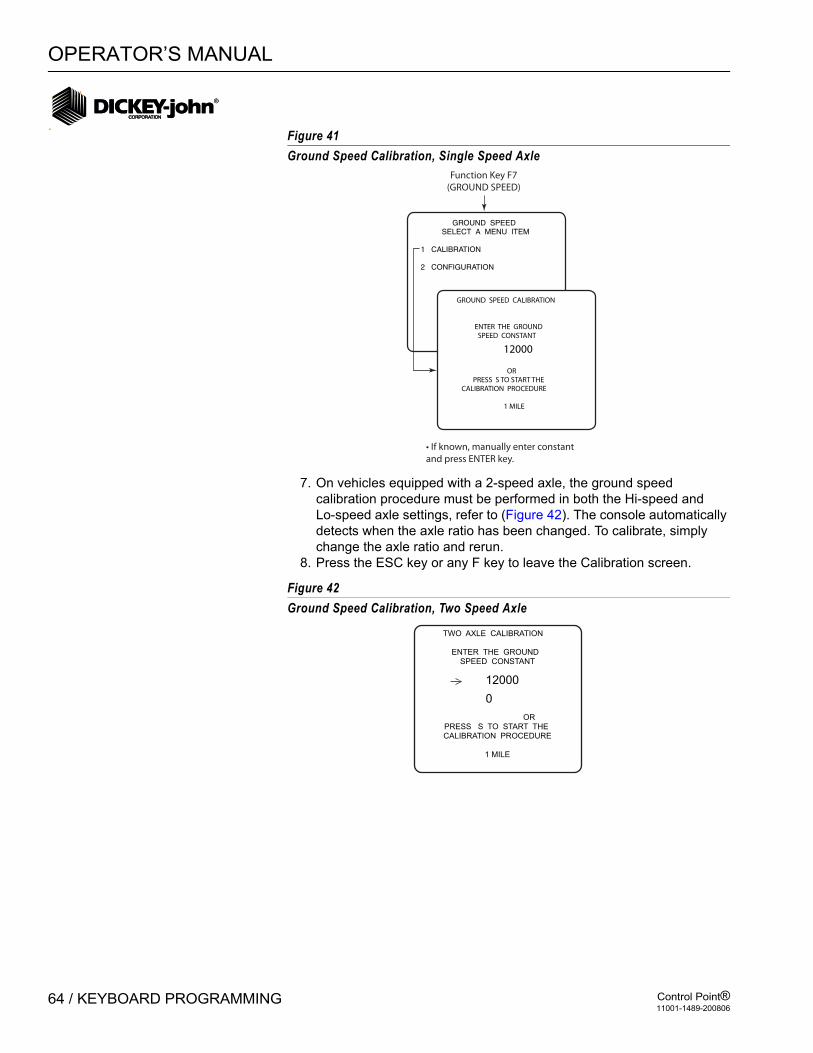
OPERATOR’S MANUAL
Control Point®11001-1489-200806
64 / KEYBOARD PROGRAMMING
Figure 41Ground Speed Calibration, Single Speed Axle
7. On vehicles equipped with a 2-speed axle, the ground speed calibration procedure must be performed in both the Hi-speed and Lo-speed axle settings, refer to (Figure 42). The console automatically detects when the axle ratio has been changed. To calibrate, simply change the axle ratio and rerun.
8. Press the ESC key or any F key to leave the Calibration screen.
Figure 42Ground Speed Calibration, Two Speed Axle
GROUND SPEED SELECT A MENU ITEM
1 CALIBRATION
2 CONFIGURATION
GROUND SPEED CALIBRATION
ENTER THE GROUND SPEED CONSTANT
OR PRESS S TO START THE CALIBRATION PROCEDURE 1 MILE
12000
Function Key F7
(GROUND SPEED)
• If known, manually enter constant
and press ENTER key.
TWO AXLE CALIBRATION
ENTER THE GROUND SPEED CONSTANT
ORPRESS S TO START THE CALIBRATION PROCEDURE
1 MILE
12000
0

OPERATOR’S MANUAL
Control Point®11001-1489-200806
KEYBOARD PROGRAMMING / 65
SPINNER CHANNEL CONFIGURATION (F8)Configuration parameters specify actuators and sensors used along with performance specifications. These values do not change unless the system hardware changes or the related calibration routines are rerun.
1. From the keyboard, press F8 to display the Spinner Configuration screen.
2. Edit the parameters on the screen. – UNLOAD - YES enables or NO disables the spinner during
unloading. – NO GND SPD - YES enables spinner operation when ground
speed is zero; NO disables at zero speed.– DRV FREQ (Drive Frequency) - Represents the valve
manufacturer’s suggested drive frequency, as shown on the valve specification sheet.
– PULSE FDBK (Pulse Feedback) - YES indicates a pulsed feedback sensor for closed loop control. NO indicates an open loop control.
– SPIN CON - Number of pulses per spinner revolution.– BLST RATE (Blast Rate) - If set to 0%, the SPREAD WIDTH
ADJUST knob position determines the spinner speed. Other values indicate the percentage of maximum spinner speed when Blast is pressed, regardless of knob setting.
– SYS RSPNS (System Response) - Adjusts the control system response time to the hydraulic and mechanical systems for a particular spreader vehicle.
– VALV BOOST (Valve Boost) - Increases the system gain initially applied to the control channel to reach final operating speed (target APR) as quickly as possible.
– AFILT - (A Filter) - Minimizes the effects of electrical noise and mechanical vibrations on the feedback signal. The smaller the number, the greater the degree of filtering. The value can be manually fine tined for best results.
– PWM OFFSET – Defines valve operating starting point.– PWM SAT – Defines valve operating end point (maximum position).
PWM OFFSET and PWM SAT are manually set for proportional valves. The Proportional Valve Spinner Procedure determines the actual values (See System Calibration section).
– GSRS Enable - The GSRS Mode (Ground Speed Related Spinner) enables the Control Point® to regulate the spinner speed related to ground speed and run closed loop. By controlling the spinner according to ground speed, the material can be dispersed at zero velocity.
– GSRS SLOPE - Spinner revolutions per MPH.– MAX GSRS - Determines the scaling of the spinner bar graph on
the Operate screen. A full bar graph indicates the max GSRS speed has been exceeded. No alarm is associated with this constant.

OPERATOR’S MANUAL
Control Point®11001-1489-200806
66 / KEYBOARD PROGRAMMING
Figure 43
Spinner Channel Configuration Screen
SPINNER CONFIGURATION
UNLOAD NONO GND SPD NODRV FREQ 100 HZPULSE FDBK NOBLST RATE 0 %PWM OFFSET 0PWM SAT 100GSRS ENABLE NO
SPINNER CONFIGURATION
UNLOAD YESDRV FREQ 100 HZPULSE FDBK NOGSRS SLPE 0.0 RPM/MPHMAX GSRS 0 MPHBLST RATE 0SYS RSPNS 10.0VALV BOOST 2.5MORE...
SPINNER CONFIGURATION
MORE...AFILT 0.18PWM OFFSET 20PWM SAT 50GSRS ENABLE YES
Spinner Config
w/NO GSRSSpinner Config
w/GSRS Enabled

OPERATOR’S MANUAL
Control Point®11001-1489-200806
KEYBOARD PROGRAMMING / 67
MONITOR & RESET ACCUMULATORS (F9)Accumulators store current run and season run totals of distance traveled, material amount, and time spent spreading materials in both the AUTO and BLAST modes. Separate totals are accumulated for each material. All of the current and season accumulators can be cleared (zeroed) from this mode (F9).
1. From the keyboard, press Function key F9 to display the Accumulators screen, refer to (Figure 44). Four selections appear - Granular, Liquid, Pause and Enable Clr from Current Total Screen.
2. Press 1 for GRANULAR or 2 for LIQUID to monitor the accumulators for corresponding materials. When pressing either the 1 or 2 key, four materials display for monitoring.
3. Press 3 PAUSE to display the current and season miles/hours driven in a Pause state.
4. Press 4 to enable/disable the clearing of the CURRENT TOTALS screen in the Operate mode.
5. If GRANULAR or LIQUID is selected from Step 2 above, select the material by pressing the corresponding key. A divided screen appears showing CURRENT totals (top half) and SEASON totals (bottom half).
To clear CURRENT totals, press C. To clear both CURRENT and SEASON totals, press S. The season totals cannot be cleared separately.
To clear accumulators for other materials, press F9 to return to the ACCUMULATOR screen and select the next material. Continue as before to clear the totals.
To enable clearing the CURRENT TOTALS screen in the OPERATE mode, press F9 to return to the ACCUMULATORS screen and then the 4 key to select the ENABLE/DISABLE CLR FROM CURRENT TOTALS SCREEN
6. To change status from enable or disable: YES causes the ENABLE/DISABLE CLEAR selection to alternate. A setting of NO leaves the ENABLE/DISABLE CLEAR status unchanged.

OPERATOR’S MANUAL
Control Point®11001-1489-200806
68 / KEYBOARD PROGRAMMING
Figure 44Access and Reset Accumulators
ACCUMULATORS SELECT A MENU ITEM
1 GRANULAR
2 LIQUID
3 PAUSE
4 ENABLE CLR FROM CURRENT TOTALS SCREEN
ENABLE / DISABLE CLEAR Y - YES N - NO
ENABLE CLEAR FROM CURRENT TOTALS SCREEN?
Press Function Key F9
(ACCUM Menu)
PAUSE TOTALS
CURRENT (C - CLR CURRENT)
PAUSE MILE 0.0 PAUSE HOURS 0.0
SEASON (S - CLR BOTH)
PAUSE MILE 0.0 PAUSE HOURS 0.0
ACCUMULATORS SELECT A MENU ITEM
1 LIQUID 1 DISABLED
2 LIQUID 2 DISABLED
3 LIQUID 3 DISABLED
4 LIQUID 4 DISABLED
ACCUMULATORS SELECT A MENU ITEM
1 SALT ENABLED
2 SAND DISABLED
3 MIX A DISABLED
4 MIX B DISABLED
SAND TOTALS
CURRENT (C – CLR CURRENT) TONS AUTO 4.5 MILES AUTO 2.8 HOUR AUTO 3.97 TONS BLAST 4.3 MILES BLAST 3.2 HOUR BLAST 0.25
SEASON (S – CLR BOTH) TONS AUTO 435.5 MILES AUTO 1536.7 HOUR AUTO 39.3 TONS BLAST 14.3 MILES BLAST 13.2 HOUR BLAST 1.25
OPERATOR’S MANUAL
Control Point®11001-1489-200806
KEYBOARD PROGRAMMING / 69
READING SYSTEM INFORMATION (F10)1. From the keyboard, press F10 to display the SYSTEM INFORMATION
screen, refer to (Figure 45). 2. Select and press the corresponding number key to view and edit the
related screen. – ALARM HISTORY - Records all alarms encountered by the system
including the time and date of each occurrence with a brief alarm description. A maximum of the latest 100 error events are logged with the oldest ones dropping out as new ones occur. The up/down arrow keys scroll the events for viewing.
– SYSTEM TOTALS - Displays time and distance totals for all materials combined. Totals display for three categories - AUTO, BLAST, and VEHICLE. These totals are ongoing and cannot be reset.
– ON/OFF HISTORY - Lists each occurrence for power on, power off, manual speed, MASTER Switch module on/off, and channel on/off with time and date for each event. A maximum of the latest 100 events are logged with the oldest events dropping out as new events occur. The up/down arrow keys scroll the events for viewing and the bottom line of the screen indicates the group of events displaying.
– RATE CHANGE HISTORY - Records each occurrence with time and date of target application rate (APR) changes. A maximum of the latest 100 events are logged with the oldest dropping out as new ones occur. The up/down arrow keys scroll the events for viewing.
– TRUCK ID - This screen allows entering an identifying name for the truck which can be changed at anytime. The entry is changed by typing the new name and then pressing the ENTER key to accept the change. A Truck ID is a required entry when using a wireless switch module.
– MATERIAL FLOW ALARM LABEL- An alarm indication that indicates low material levels when a Hopper Lever sensor of material flow sensor is used. The Material Flow Alarm Label is user-definable up to 22 characters.
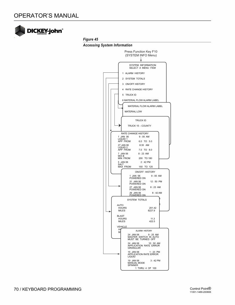
OPERATOR’S MANUAL
Control Point®11001-1489-200806
70 / KEYBOARD PROGRAMMING
Figure 45Accessing System Information
SYSTEM INFORMATION SELECT A MENU ITEM
1 ALARM HISTORY
2 SYSTEM TOTALS
3 ON/OFF HISTORY
4 RATE CHANGE HISTORY
5 TRUCK ID
6 MATERIAL FLOW ALARM LABEL
Press Function Key F10
(SYSTEM INFO Menu)
MATERIAL FLOW ALARM LABEL
MATERIAL LOW
1 THRU 4 OF 25
1 THRU 4 OF 25
RATE CHANGE HISTORY
1 JAN 06 9 : 05 AMLIQUID 1APP FROM 6.0 TO 5.0
27 JAN 06 8:35 AMLIQUID 2 APP FROM 7.0 TO 8.0
7 JAN 06 8 : 23 AMMIX BMIN FROM 200 TO 180
5 JAN 06 2 : 42 PMSALT MAX FROM 150 TO 120
TRUCK ID
TRUCK 15 – COUNTY
ON/OFF HISTORY
24 DEC 98 3 : 42 PM POWERED ON
26 JAN 06 8 : 42 AM POWERED ON
27 JAN 06 8 : 23 AM POWERED ON
31 JAN 06 12 : 50 PM POWERED ON
1 JAN 06 9 : 00 AMPOWERED ON
4 DEC 98 1 : 32 PM POWERED ON
SYSTEM TOTALS
AUTO HOURS 201.42 MILES 8227.9
BLAST HOURS 11.3 MILES 422.5
VEHICLE HOURS 393.73 MILES 16289.2
ALARM HISTORY
19 JAN 06 3 : 42 PM MANUAL MODESPINNER
15 JAN 06 1 : 23 PMAPPLICATION RATE ERRORLIQUID
24 JAN 06 10 : 50 AM APPLICATION RATE ERRORGRANULAR
24 JAN 06 9 : 25 AMMASTER SWITCH IN AUTOMUST BE TURNED OFF
1 THRU 4 OF 100
OPERATOR’S MANUAL
Control Point®11001-1489-200806
KEYBOARD PROGRAMMING / 71
PERFORMING SYSTEM RESPONSE (F11)After all configuration constants have been entered for a given vehicle, the SYSTEM RESPONSE must be performed in preparation for spreading materials as described in the System Calibration section.

OPERATOR’S MANUAL
Control Point®11001-1489-200806
72 / KEYBOARD PROGRAMMING
OPERATOR’S MANUAL
Control Point®11001-1489-200806
SYSTEM CALIBRATION / 73
SYSTEM CALIBRATION
Due to the many combinations of hydraulic/liquid pumps, valves and motors plus the different material delivery systems, each spreader truck becomes unique. System calibration defines the spreader configuration characteristics for optimum accuracy of the Control Point® system. Performing the following procedures in the order outlined ensures the greatest accuracy when finished.
RECORDING CALIBRATION DATAAfter finishing each routine, record the calibration constant on the CALIBRATION DATA RECORD sheets at the rear of this manual. If console replacement becomes necessary, most system parameters can be quickly transferred to the new unit via wireless transfer (Control Point® version 7.27 or higher with wireless base station) or keyboard entry.
If additional sheets are required, make copies and keep them with this manual.
REPEATING CALIBRATION RUNSTo minimize operator and other procedural errors, most tests should be repeated several times (three times), average the results, and keyboard enter the constants. The SYSTEM RESPONSE CALIBRATION does not require repeating.
MAINTAINING CALIBRATION ACCURACYThe below conditions should be followed to maintain accurate system calibration.
1. If a new material is added and the spreader, nozzle, or flowmeter constant is not accurately known, the GRANULAR or LIQUID CALIBRATION routine must be run.
2. If wear of the conveyor/auger mechanism, actuator valves, flowmeter, nozzles, or other system components is suspected, a new catch test (GRANULAR or LIQUID CALIBRATION) should be performed to re-establish APR accuracy.
3. After installing new or different tires, the GROUND SPEED CALIBRATION should be repeated.
4. Each known physical (mechanical) change in the system should be followed immediately by a SYSTEM RESPONSE calibration on the related control channel (granular, liquid pre-wet, liquid anti-ice, or spinner).
5. Repair or replacement of any system components, including hydraulic hoses, fluid changes and even normal wear, make it necessary to periodically recalibrate the system.
6. Even without known changes, the SYSTEM RESPONSE CALIBRATIONS should be performed at minimum intervals of one year. A good rule of thumb is to recalibrate all three control channels at the start of each spreader season.

OPERATOR’S MANUAL
Control Point®11001-1489-200806
74 / SYSTEM CALIBRATION

OPERATOR’S MANUAL
Control Point®11001-1489-200806
SYSTEM CALIBRATION / 75
CALIBRATION SYSTEM RESPONSE (F11)These constants adjust the response time of the Control Point® system to the hydraulic and mechanical systems. This procedure determines the System Response (SYS RSPNS) and related constants (VALV BOOST, PWM OFFSET, and AFILT) for each of the three control channels (granular, liquid, and spinner).
Constants normally vary slightly each time a SYSTEM RESPONSE CALIBRATION is run. Manual fine-tuning for optimum performance is permissible (See paragraph "Fine-tuning System Response Parameters"). To maintain a performance history, always record new constants on the CALIBRATION DATA RECORD sheets each time a routine is run or fine-tuned.
– GRANULAR - During calibration, a set of values for SYS RSPNS, VALV BOOST, PWM OFFSET, and AFILT automatically calculate, store, and display on the GRANULAR CONFIGURATION screens for all (up to four) granular materials.
– LIQUID PR-WET - The pre-wet spray bar and anti-icing boom liquids require separate procedures due to differences in flowmeters, nozzles, and plumbing components. Calibration establishes a similar set of parameters as above for all pre-wet liquid materials.
– LIQUID ANTI-ICING - Calibration establishes a similar set of parameters as above for all anti-ice materials used on the system.
– SPINNER - Calibration determines the spinner channel parameters and correlates the fully clockwise position of the WIDTH ADJUST knob with the 100% mark on the SPREAD WIDTH bar display.
GRANULAR SYSTEM RESPONSE CALIBRATIONLiquid prewet and liquid anti-ice channels are very similar and, therefore, not specifically described or shown.
1. Press F11 to obtain SYSTEM RSPN CALIBRATION menu. Four choices display, refer to (Figure 46).
2. Press 1 to select GRANULAR. A warning screen states CALIBRATION WILL ACTIVATE THE SELECTED CHANNEL when the test begins.
3. When ready to start, press “R” on the keyboard. A screen appears to indicate CALIBRATING. When finished, a screen appears stating SYS RSPNS DONE.

OPERATOR’S MANUAL
Control Point®11001-1489-200806
76 / SYSTEM CALIBRATION
Figure 46System Response Calibration Screens
4. When the calibration is complete, press the "C" key to continue as prompted at the bottom of the screen. The resulting values automatically record in the proper locations. Access the GRANULAR CONFIG Function (F3) and copy the numbers to the CALIBRATION DATA RECORD SHEET in the rear of the manual.
SYS RSPNS CALIBRATION SELECT A MENU ITEM
1 GRANULAR
2 LIQUID PRE-WET
3 LIQUID ANTI-ICING
4 SPINNER
SYS RSPNS CALIBRATIONGRANULAR
- - WARNING - -
THIS CALIBRATIONWILL ACTIVATE THE
SELECTED CHANNEL .
STARTING THISPROCEDURE WILL CAUSE
MATERIAL TODISPENSE .
PRESS R TO RUN
Press Function Key F11
(SYSTEM RESP)
SYS RSPNS CALIBRATIONGRANULAR
OPEN FULL
PRESS S TO STOP
CALIBRATING
SYS RSPNS CALIBRATIONGRANULAR
PRESS C TO CONTINUE
SYS RSPNS DONE
See Notebelow
• FULL OPEN is the first step in theautomatic calibration. Approximately12 more steps display while calculatingbefore the SYS RSPNS DONE screen appears.• SPINNER Calibration ask you to turn Knobon Switch to 100% before ending procedure.

OPERATOR’S MANUAL
Control Point®11001-1489-200806
SYSTEM CALIBRATION / 77
5. Repeat this procedure for the remaining control channels. Multiple runs and averaging results are unnecessary. Liquid must be primed before running a system response. The UNLOAD feature can be used to prime the pump.
FINE TUNING SYSTEM RESPONSE CONSTANTSThe Automatic System Response routines are not necessarily exact. Operators may want the system to respond faster or slower than calculated by the automatic routines. These values can be adjusted slightly to tailor the response to operator needs.
IMPORTANT: Automatic routines must always be run prior to modification to establish basic values. The following are a few general guidelines.
Figure 47Proportional Valve Spinner Calibration Screens
SYS RSPNS CONSTANTIf the control system responds slowly to changes in speed and is slow to start, the SYS RSPNS value should be increased. If the system is oscillating around the target APR, the SYS RSPNS may be too large and should be decreased. Excessive oscillation should be limited to ±5% of the target APR to minimize wear on the PWM valve. Most systems can be tuned by altering only this value.
SPINNER CONFIGURATION
UNLOAD NONO GND SPD NODRV FREQ 100 HZPULSE FDBK NOGSRS SLPE 0.0 RPM/MPHMAX GSRS 0 MPHBLAST RATE 0 %SYS RSPNS 10.0VALV BOOST 2.5MORE . . .
SPINNER CONFIGURATION
MORE . . .AFILT 0.250000PWM OFFSET 15PWM SAT 100GSRS ENABLE YES
Press Function Key F8
(SPINNER)
(No Function screen appears)
• PWM SAT and SPRD LIMIT appears only
for proportional valve
OPERATOR’S MANUAL
Control Point®11001-1489-200806
78 / SYSTEM CALIBRATION
VALV BOOSTThis value increases SYS RSPNS only at start-up to more quickly start system spreading. The value does not affect stability when operating at the target APR and does not normally require changing.
AFILTThis value defines the amount of feedback noise rejection. The smaller the number, the greater the filtering. Noisy feedback sensors cause the APR's to randomly jump around. Decreasing the AFILT may reduce the problem but also can cause the system to become more sluggish. Typically, this value does not require changing, but check the response time if fine tuning becomes necessary.
PROPORTIONAL VALVE SPINNER CALIBRATIONThis calibration determines appropriate values for PWM OFFSET and PWM SAT when using a proportional valve with no feedback sensor to drive the spinner channel, refer to (Figure 47).
1. With the spinner width adjust knob fully counterclockwise (CCW), verify the spinner is not rotating. These checks must be performed in the Operate mode. Rotate the spinner width adjust knob clockwise (CW) one position and verify spinner rotates slowly. If it rotates too fast, decrease OFFSET by one (1). If it rotates too slowly, increase OFFSET by one (1).
2. With the spinner width adjust knob fully clockwise (CW), verify the spinner is running at full speed. If it is rotating too slowly, increase the SAT value by one (1) and recheck. Repeat as necessary. The maximum value for SAT is 100.
3. If the spinner turns too fast, decrease the SAT value until a satisfactory maximum speed is obtained. The SAT value must be greater than the OFFSET value.

OPERATOR’S MANUAL
Control Point®11001-1489-200806
SYSTEM CALIBRATION / 79
GRANULAR MATERIALS CALIBRATION (F6)The GRANULAR CALIBRATION determines the spreader constant (SPR CON) for a given granular material. The spreader constant is the number of pulses generated by the application rate sensor per pound of granular material discharged. A separate calibration routine must be run for each granular material used.
GRANULAR CALIBRATION (also referred to as a granular "catch test") causes the control system to run the conveyor/auger mechanism, dispensing material while the vehicle is stationary. When a sufficient amount of material has been discharged, the operator stops the spreader mechanism, weighs the material discharged, and keyboard enters the amount. The system then calculates, stores, and displays the SPR CON.
The procedural steps are as follows:
1. Load the vehicle hopper with the desired material and verify the gate height is adjusted to the proper setting on V-Box spreaders. If tailgate spreads are in use, make sure auger is full. Load enough material to provide a uniform flow throughout the calibration procedure.
2. Position a suitable container or drop cloth to catch all dispensed material from the conveyor/auger. The container must be large enough to obtain a good, representative sample. The larger the sample weighed, the better the accuracy. Alternatively, if a vehicle scale is available, weigh the truck before and after dispensing material.
3. Press Function key F6 to access the CALIBRATION MENU screen. Press the 1 key to select GRANULAR CALIBRATION.
4. Select the granular material for calibration (keys 1 - 4). The words ENABLED and DISABLED after the selected product have no significance to the calibration. (Figure 48) illustrates the SALT CALIBRATION selection. Other selections are equivalent.
A warning message displays STARTING THIS PROCEDURE WILL CAUSE MATERIAL TO DISPENSE. Ensure all personnel are clear before starting the next step.
IMPORTANT: If using a Gate Height Sensor, calibration must be verified before the Spreader Calibration.

OPERATOR’S MANUAL
Control Point®11001-1489-200806
80 / SYSTEM CALIBRATION
Figure 48Granular Calibration
5. With the vehicle stationary, engage the hydraulic system. Increase engine RPMs to normal operating range.
6. Press “R” on the keyboard to run the conveyor/auger and start the calibration. The number in the middle of the screen shows the counts accumulating from the APR sensor. If a count is not recorded and stays on “0”, stop the test and check the application rate sensor.
CALIBRATION MENU SELECT A MENU ITEM
1 GRANULAR
2 LIQUID
3. SPINNER WIDTH
GRANULAR CALIBRATION SELECT A MENU ITEM
1 SALT ENABLED
2 SAND DISABLED
3 MIX A DISABLED
4 MIX B DISABLED
SALT CALIBRATION
– – WARNING – –
THIS CALIBRATIONWILL ACTIVATE THE
SELECTED CHANNEL .
STARTING THISPROCEDURE WILL CAUSE
MATERIAL TODISPENSE .
CATCH MATERIAL INWEIGHED CONTAINER
PRESS R TO RUN
SALT CALIBRATION
CALIBRATING
25610
Gate Height 2.0 IN
PRESS S TO STOP
SALT CALIBRATION
SPR CON 150.00 P/LBSCOUNTS 25610
ENTER THE AMOUNT DISPENSED IN POUNDS
—
PRESS D WHEN DONE
Press Function Key F6
(CAL)

OPERATOR’S MANUAL
Control Point®11001-1489-200806
SYSTEM CALIBRATION / 81
7. When a sufficient amount of material has been dispensed, press “S” to stop the system. A screen appears showing the previous SPR CON and the sensor COUNTS accumulated during the current run. The screen asks for an entry of pounds before proceeding. Perform the next step while the screen waits for the results.
8. If using a vehicle scale, reweigh the truck and calculate the amount of material dispensed in pounds.
9. Enter that number into the console and press ENTER. Press “D” when finished. The spreader constant (SPR CON) is now stored and displayed on the SALT CALIBRATION screen and on the GRANULAR CONFIGURATION screen for this material.
10. For maximum accuracy, repeat the entire procedure at least three times. Temporarily write down the resulting SPR CON each time. Average the results and keyboard enter the average as the final SPR CON. Then record the SPR CON for this material on the CALIBRATION DATA RECORDS sheets at the rear of this manual.
11. Repeat this procedure for each granular material used.
GRANULAR CALIBRATION FINE TUNINGIf small but consistent application rate errors are observed over a period of time, the spreader constant can be modified to fine-tune application accuracy. See Appendix A for steps required to calculate the new spreader constant, which is then keyboard entered on the (F3) GRANULAR CONFIGURATION screen. Alternatively, the GRANULAR CALIBRATION routine can be repeated to correct this type of APR error.
LIQUID MATERIALS CALIBRATION (F6)The LIQUID CALIBRATION determines a flowmeter constant (K-FACTOR) for each liquid material used. The K-FACTOR represents the number of pulses generated by the flowmeter per gallon of liquid dispensed. The NZLE CNST is a measure of flow rate through the nozzle at a standard pressure. Separate calibrations are necessary for each liquid material because of viscosity differences.
The LIQUID CALIBRATION routine (also referred to as a liquid "catch test") causes the control system to run the liquid pump, dispensing material while the vehicle is stationary. When a sufficient amount of liquid has been discharged, the operator stops the system, weighs the discharged liquid, and keyboard enters the amount. The system then calculates, stores, and displays the K-FACTOR (NZLE CNST).
The procedural steps are as follows:
1. Load vehicle tank with the material.2. Position a suitable container to catch all the material dispensed
through the liquid pump. The container must be large enough to obtain a good, representative sample. The larger the sample weighed, the higher degree of accuracy. When calibrating a pre-wet liquid material, the pre-wet bar may be removed from its mounting and placed inside the catch container. Alternatively, especially for flowmeter based anti-ice liquid materials, temporarily disconnect an appropriate hose and place inside the catch container.

OPERATOR’S MANUAL
Control Point®11001-1489-200806
82 / SYSTEM CALIBRATION
3. Press Function key F6 to access the CALIBRATION MENU screen. Press the 2 key to select LIQUID for the FLOWMETER CALIBRATION screen, refer to (Figure 49).
4. Select the liquid material for calibration (key 1 - 4).The words ENABLED and DISABLED after the selected product have no significance to the calibration. Figure 39 illustrates the LIQUID 1 CALIBRATION selection. Other selections are equivalent. For pressure based anti-ice systems, it is necessary to enter a target pressure. This should be the nozzle manufactures rating pressure, typically 40 psi (2.75 bar).
Note: If running pressure, make sure booms are drained prior to running “OFFSET”.
A warning message displays stating STARTING THIS PROCEDURE WILL CAUSE MATERIAL TO DISPENSE. Ensure all personnel are clear before starting the next step.
5. In the case when ONLY the liquid channel is propelled by the hydraulic system, start the engine, keeping the vehicle stationary. Engage the hydraulic system, and increase engine RPMs to normal operating range.
6. Press “R” on the keyboard to run the liquid pump and start the calibration routine. For flowmeter based systems, use the liquid channel “+/-” switch on the Switch Module, as necessary, to obtain an adequate discharge rate. The number displayed indicates the accumulating count from the APR sensor.
7. When a sufficient amount of liquid has been dispensed, press “S” to stop. For a flowmeter based system, a screen appears showing the previous K-FACTOR and the sensor counts accumulated during the current run. For a pressure based system, the previous NZLE CNST and collection time are displayed. The screen asks for an entry of gallons before proceeding. Perform the next step while the screen waits for the results.
8. Weigh the material caught and calculate the amount dispensed in gallons.
9. Enter that number into the console and press “ENTER”. Press “D” when finished. The flowmeter constant (K-FACTOR or NZLE CNST) is now stored and displayed on this screen and on the LIQUID CONFIGURATION screen for this material.
10. For maximum accuracy, repeat the entire procedure at least three times. Temporarily write down the resulting K-FACTOR (NZLE CNST) each time. Average the results and keyboard enter the average as the final K-FACTOR (NZLE CNST). Then record the K-FACTOR (NZLE CNST) for this material on the CALIBRATION DATA RECORDS sheets at the rear of this manual.
11. Repeat this procedure for each liquid material used.
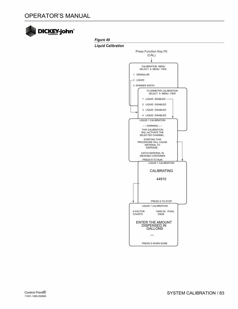
OPERATOR’S MANUAL
Control Point®11001-1489-200806
SYSTEM CALIBRATION / 83
Figure 49Liquid Calibration
CALIBRATION MENU SELECT A MENU ITEM
1 GRANULAR
2 LIQUID
3. SPINNER WIDTH
FLOWMETER CALIBRATION SELECT A MENU ITEM
1 LIQUID ENABLED
2 LIQUID DISABLED
3 LIQUID DISABLED
4 LIQUID DISABLED
LIQUID 1 CALIBRATION
– – WARNING – –
THIS CALIBRATIONWILL ACTIVATE THE
SELECTED CHANNEL .
STARTING THISPROCEDURE WILL CAUSE
MATERIAL TODISPENSE .
CATCH MATERIAL INWEIGHED CONTAINER
PRESS R TO RUN
LIQUID 1 CALIBRATION
CALIBRATING
44910
PRESS S TO STOP
LIQUID 1 CALIBRATION
K-FACTOR 10000.00 P/GALCOUNTS 53636
ENTER THE AMOUNT DISPENSED IN GALLONS
—
PRESS D WHEN DONE
Press Function Key F6
(CAL)

OPERATOR’S MANUAL
Control Point®11001-1489-200806
84 / SYSTEM CALIBRATION
LIQUID CALIBRATION FINE TUNINGIf, after using a flowmeter or nozzle constant over a period of time, small but consistent application rate errors are observed, its value can be manually changed to fine-tune application accuracy. See Appendix A to calculate the modified flowmeter constant, which is then keyboard entered on the LIQUID CONFIGURATION (F5) screen. Alternatively, the LIQUID CALIBRATION routine can be repeated to correct this type of APR error.
CALIBRATING SPINNER WIDTH (F6) The spinner width calibration determines the spread width as indicated by the spinner knob position for area based units (i.e. MILE-FEET, SQ FEET, SQ YARD, KILOMETER-METER, and SQ METER). Area based units are selected in the Miscellaneous menu (F12) under SYSTEM UNITS (Item 3). Since vehicles vary, a multi-point calibration is necessary to assure accurate spreading throughout the spinner knob range. Also, material densities vary requiring separate calibrations.
1. Load the vehicle with material.2. Press Function key F6 to access the CALIBRATION MENU. Press the
3 key to select SPINNER WIDTH.3. Select a material for calibration (Items 1 through 4). The words
ENABLED and DISABLED after the selected product has no significance to the calibration. Figure 50 illustrates SALT CALIBRATION; other selections are equivalent.
4. Place the Spinner Knob at 0 and press R. The spinner mechanism actives after pressing R. Placing the knob at 0 shuts the spinner off. This verifies the valve OFFSET value is correct.
5. Rotate the Spread Width knob to 20. Measure and record the width material is spread. Repeat at 40, 60, 80, and 100. The arrow on the left side of the screen automatically follows the Spread Width knob setting. The arrow position allows measured widths to be entered into the proper location.
6. Press S to stop the routine when finished.

OPERATOR’S MANUAL
Control Point®11001-1489-200806
SYSTEM CALIBRATION / 85
Figure 50Spinner Width Calibration
CALIBRATION MENU SELECT A MENU ITEM
1 GRANULAR
2 LIQUID
3. SPINNER WIDTH
SPIN WIDTH CALIBRATION SELECT A MENU ITEM
1 SALT ENABLED
2 SAND ENABLED
3 MIX A DISABLED
4 MIX B DISABLED
SALT WIDTHS NOT CALIBRATEDPOSITION 20 0.0 FTPOSITION 40 0.0 FTPOSITION 60 0.0 FTPOSITION 80 0.0 FTPOSITION 100 0.0 FT
– – WARNING – – CALIBRATE STARTS MATERIAL FLOW
PRESS R TO RUN
Press Function Key F6
(CAL)

OPERATOR’S MANUAL
Control Point®11001-1489-200806
86 / SYSTEM CALIBRATION
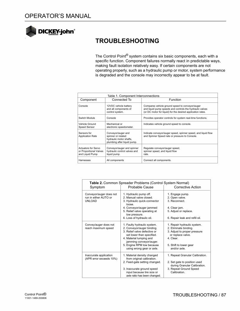
OPERATOR’S MANUAL
Control Point®11001-1489-200806
TROUBLESHOOTING / 87
TROUBLESHOOTING
The Control Point® system contains six basic components, each with a specific function. Component failures normally react in predictable ways, making fault isolation relatively easy. If certain components are not operating properly, such as a hydraulic pump or motor, system performance is degraded and the console may incorrectly appear to be at fault.
Table 1. Component Interconnections
Component Connected To Function
Console 12VDC vehicle battery Compares vehicle ground speed to conveyor/auger
and all components of and liquid pump speeds and controls the hydraulic valves
control system. (or DC motor for liquid) for the desired application rates.
Switch Module Console Provides operator controls for system real-time functions.
Vehicle Ground Mechanical or Indicates vehicle ground speed to console.
Speed Sensor electronic speedometer.
Sensors for Conveyor/auger and Indicate conveyor/auger speed, spinner speed, and liquid flow
Application Rate spinner or related and Spinner Speed rate or pressure to Console.
hydraulic motor shafts,
plumbing after liquid pump.
Actuators for Servo Conveyor/auger and spinner Regulate conveyor/auger speed,
or Proportional Valves hydraulic control valves and spinner speed, and liquid flow
and Liquid Pump liquid pump. rate.
Harnesses All components Connect all components.
Table 2. Common Spreader Problems (Control System Normal)
Symptom Probable Cause Corrective Action
Conveyor/auger does not 1. Hydraulic pump off. 1. Engage pump.
run in either AUTO or 2. Manual valve closed. 2. Open valve.
UNLOAD 3. Hydraulic quick-connector 3. Reconnect.
loose.
4. Conveyor/auger jammed 4. Clear jam.
5. Relief valve operating at 5. Adjust or replace.
low pressure.
6. Loss of hydraulic oil. 6. Repair leak and refill oil.
Convey/auger does not 1. Faulty hydraulic system. 1. Repair hydraulic system.
reach maximum speed 2. Conveyor/auger binding. 2. Eliminate binding.
3. Relief valve defective or 3. Adjust to proper pressure
set lower than specified. or replace valve.
4. Material lumping and 4. Clear.
jamming conveyor/auger.
5. Engine RPM low because 5. Shift to lower gear
using wrong gear or axle. and/or axle.
Inaccurate application 1. Material density changed 1. Repeat Granular Calibration.
(APR error exceeds 10%) from original calibration.
2. Feed-gate setting changed. 2. Set gate to position used
during Granular Calibration.
3. Inaccurate ground speed 3. Repeat Ground Speed
input because tire size or Calibration.
axle ratio has been changed.

OPERATOR’S MANUAL
Control Point®11001-1489-200806
88 / TROUBLESHOOTING
CONSOLE DOES NOT POWER ONCorrective Action
1. Check for blown fuse, located in positive battery lead. If blown, replace with blade-type, same size fuse.
2. Check for poor connections to the battery; remove any corrosion. Also check battery polarity.
3. Check the red ignition wire.4. Visually inspect power cable from rear of Console to battery. If
damaged, replace cable/repair.5. If no problem can be found with power connection or power cable,
console may be at fault. Contact DICKEY-john Technical Support at 1-800-637-3302.
MANUAL MODE FLASHES ON DISPLAY
Probable CauseIf the words “MANUAL MODE” are flashing on the display, the Control Point® system may have reverted to the manual override function to compensate for a sensor failure (liquid flowmeter, conveyor/auger sensor or spinner sensor). If so, the system is operating in open loop control to allow spreading/spraying to continue until sensor repair/replacement is possible.
Corrective Action for Granular System:1. If material is not spreading (Conveyor or auger stopped). • Make sure the PTO is engaged. • Check for lodged obstacles in conveyor or auger. • Check for a hydraulic system failure (pump, valve, hydraulic motor).
2. If material is spreading (conveyor or auger turning).• Check for a disconnected or slipping conveyor sensor coupling.• Unplug connector nearest the conveyor sensor. Check for +12V
between the RED and BLK wires and +8V between the GRN and BLK wires. Absence of either voltage indicates a broken or shorted wire within the cable assembly or a corroded pin in the connector. If voltages are present, replace the conveyor sensor.
Corrective Action for Liquid System1. If liquid is not spraying.• Check tanks for proper level.• Check liquid filters for plugging.• Check pump and wires to pump for corrosion and correct voltage.2. If liquid is spraying.• Check flowmeter for debris jamming the paddle wheel. • Unplug the connector nearest the flowmeter sensor. Check for +12V
between the RED and BLK wires and +8V between the GRN and BLK wires. The absence of either voltage indicates a broken or shorted wire

OPERATOR’S MANUAL
Control Point®11001-1489-200806
TROUBLESHOOTING / 89
within the cable assembly or a corroded pin in the connector. If voltages are present, repair/replace the flowmeter sensor.
AUTO INOPERATIVE; UNLOAD OPERATES
Probable CauseIf the spreader/sprayer does not function when the MASTER Switch is in AUTO but does in the UNLOAD position, the ground sensor may have failed.
Corrective Action 1. Check the ground speed reading (MPH) on the console. If the ground
speed reading is 0 when the truck is moving;• Check wires and connections between the DICKEY-john ground speed
sensor and the console.• Check wires and connections between the DICKEY-john ground speed
sensor and the transmission speed sensor.2. Check the ground speed calibration number programmed in the
console (F7). Compare the number to the original setting. Typically, the constant should be between 35000 to 60000.
3. Next, replace the ground speed sensor.4. If the failure continues, replace the MASTER switch module and then
the console.
IMPORTANT: The Control Point® system can continue operating without a “true” ground speed sensor input by setting the MANUAL SPEED to YES in the GROUND SPEED CONFIGURATION (F7) screen. With this enabled, the console simulates an artificial ground speed signal which appears on the display.
To spread/spray in this mode, set the MASTER Switch to the AUTO position and drive the truck at the displayed SPEED. To stop spreading, switch the MASTER Switch back to the OFF position.
DISPLAYED APR FLUCTUATES
Probable CauseIf the actual APR displaying on console fluctuates more than 5% above and below the target APR while the vehicle maintains a steady speed, the System Response should be investigated.
Corrective Action1. System Response (SYS RSPNS) constant is too large. See heading
"Fine-tuning System Response Constants" in the System Configuration section.
2. Check APR sensor for loose coupling or slipping on shaft.

OPERATOR’S MANUAL
Control Point®11001-1489-200806
90 / TROUBLESHOOTING
DISPLAYED APR RESPONDS SLOWLY
Probable CauseIf the actual APR displaying on the console is slow responding to ground speed or target APR changes or stabilizes at the wrong value, the System Response may require fine tuning.
Corrective Action1. System Response (SYS RSPNS) constant may be too small. Refer to
Fine-tuning System Response Constants section.
SPINNER ROTATIONAL SPEED INCORRECTCorrective Action
1. Check PWM OFFSET and PWM settings in SPINNER mode (F8) for incorrect setting.
2. Check for variations in granular material density dropping onto the spinners from the conveyor/auger.
3. On proportional valves, increases in electrical coil resistance due to heat buildup can cause valve position shifts, resulting in speed changes.
4. Check for drag due to snow and ice buildup.

OPERATOR’S MANUAL
Control Point®11001-1489-200806
TROUBLESHOOTING / 91
APPLICATION RATE ERROR
Probable CauseIf an APPLICATION RATE ERROR flashes on the display and the alarm sounds, a fully open valve is indicated but the target APR cannot be achieved.
Corrective Action for Granular System1. Reduce the truck ground speed to allow the system to catch up and the
error to clear.2. Shift to a lower gear to increase engine RPM and hydraulic pump
rotation.3. Check hydraulic disconnects and filter.4. Ensure correct spreader constant is programmed into console. Check
original setting or run a Granular Calibration (F6).5. Incorrect PWM SAT setting (See Granular Configuration screen - F3).
Compare against original setting or run System Response on the Granular channel (F11) setting.
6. Check for insufficient hydraulic oil flow at normal engine RPM. 7. Check spreader valve, electrical connections to the valve coil,
resistance of the coils (See manufacturers specifications), and verify voltage from control console.
Corrective Action for Liquid System1. Check to see if the liquid tanks are low, shut off valves are partially
closed, bypass valves are open too far, or an obstruction is in the liquid tank outlet.
2. Check filters between the liquid tank and suction side of the liquid pump for blockage.
3. Check for plugged nozzles or nozzles that are too small to supply sufficient gallons per minute.
4. If using a electric liquid pump, check that the nozzle pressure (spray bar pressure) does not exceed 40 psi. Some electric pumps have an internal pressure switch to shut pump off high back pressure conditions.
5. Ensure a correct K-FACTOR is programmed. Compare it against the number stamped on the flowmeter body or recorded on the Calibration Data Record Sheet. If original settings are not available, run a Liquid Calibration (F6).
6. Observe the PWM SAT under the Liquid Configuration screen (F5). Compare against original setting. If not available, run a System Response on the Liquid Channel (F11).

OPERATOR’S MANUAL
Control Point®11001-1489-200806
92 / TROUBLESHOOTING
SYSTEM DOES NOT OPERATE
Probable CauseIf the system does not respond with the Master switch in Auto or Unload or the Blast button has not effect, the hydraulic valve may not be opening to supply hydraulic oil to the conveyor motor (spreader system) or the pump may not be rotating to supply liquid to the spray bar (liquid system).
Corrective ActionThe following four steps describe repair for a pulse width modulated hydraulic valve (Rexroth, Gresen, Vickers, Parker, etc.). Begin by disconnecting the electrical connections at the solenoid coil and then set the MASTER Switch into UNLOAD position to prevent possible damage to the PWM valve driver and coil.
1. Check voltage readings on the granular valve connector of the main harness at pin 16 and 8. Use pin 15 as ground. Pin 16 should read battery voltage (+12V); pin 8 reads a percentage of +12V determined by PWM SAT value entered under Granular Configuration (F3). (i.e. If PWM SAT is 40, then a reading of +4.8 V. –12 x .40 = 4.8 be present).
2. Check voltage readings at the solenoid valve coil. The WHT wire supplies the PWM voltage signal to the coil; the GRY wire is signal ground. Voltage reading should be equal to reading in step above. If voltages are not present, check wiring harnesses for cuts or shorts.
3. If voltages are present a hydraulic valve or hydraulic flow problem is indicated.
4. If the above checks are normal, replace the PWM valve driver. If this does not the solve problem, replace the console.
Corrective Action for Granular ChannelBegin by disconnecting the electrical connections at the solenoid coil. Then set the MASTER switch to the UNLOAD position for the following two steps to prevent possible actuator damage.
1. Check voltage readings on the granular valve connector of the main harness at pins 16 and 8. Use pin 15 as ground. Pin 16 and 8 should read battery voltage (+12V).
2. If voltages are present and actuator does not rotate, replace the actuator.
3. If voltages are not present replace main harness, valve extension cable, or console.
Corrective Action for a Sprayer ChannelIf the sprayer system is not spraying, begin by disconnecting the electrical connections at the pump or solenoid coil. Then switch the MASTER switch to the UNLOAD position for the following checks to prevent possible damage to the liquid valve driver and coil.
1. Check voltage reading on the RED and BRN wires at the liquid valve connector of the main harness. Use the BLK wire as ground.

OPERATOR’S MANUAL
Control Point®11001-1489-200806
TROUBLESHOOTING / 93
The RED wire should read battery voltage (+12V) and the BRN wire should read a voltage equal to a percentage of +12V determined by PWM SAT value entered under LIQUID CONFIGURATION (F5) (i.e. If PWM SAT is 90, then a reading of +10.8V –12 x .9 = 10.8 should be present).
Check voltage readings at the pump or solenoid coil on the valve. The RED wire supplies the PWM voltage signal to the pump or solenoid coil, while the BLK wire is signal ground. Voltage reading should be equal to those above.
2. If voltages are present but sprayer does not spray, the pump, solenoid coil, hydraulic valve, or hydraulic flow may be faulty.If voltages are not present, check wiring harnesses for cuts or shorts, then replace the liquid valve driver. If this does not solve problem, replace the console.
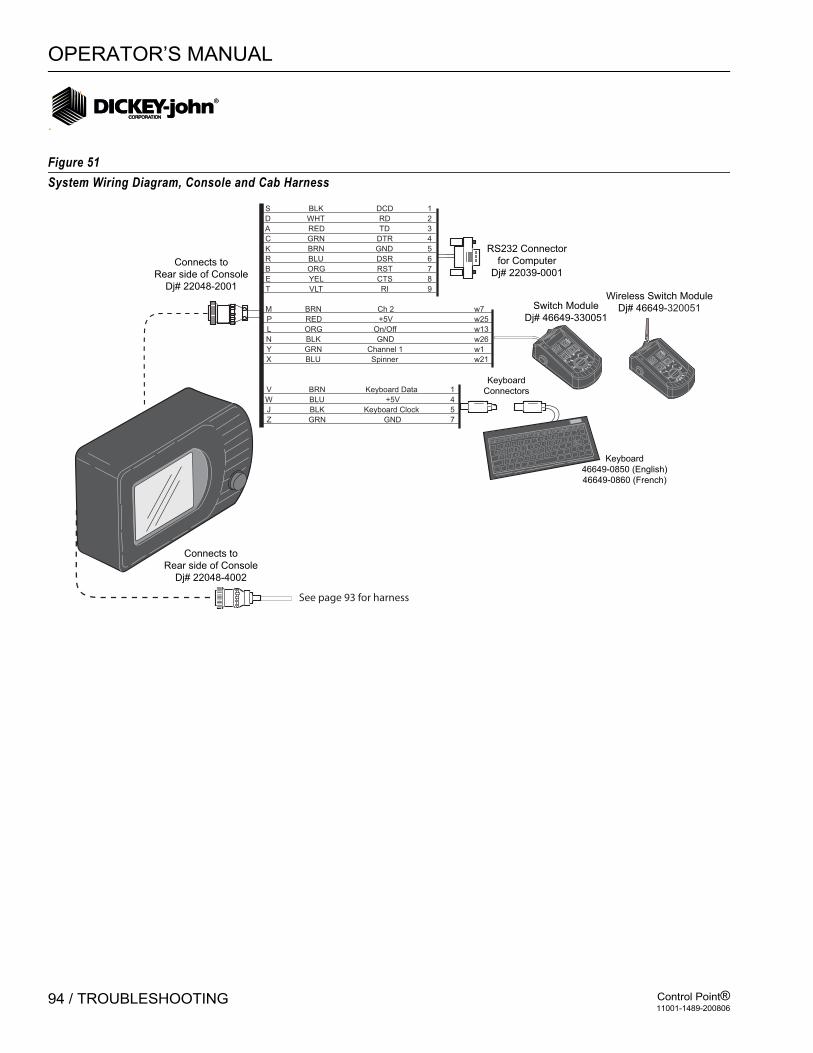
OPERATOR’S MANUAL
Control Point®11001-1489-200806
94 / TROUBLESHOOTING
Figure 51System Wiring Diagram, Console and Cab Harness
RS232 Connector
for Computer
Dj# 22039-0001
Keyboard
Connectors
Switch Module
Dj# 46649-330051
Keyboard
46649-0850 (English)
46649-0860 (French)
Connects to
Rear side of Console
Dj# 22048-4002
Connects to
Rear side of Console
Dj# 22048-2001
OFF AUTO U
NLOAD
MASTER
0
0
40
60
80
100
BLAST
BRNM Ch 2 w7
P RED +5V w25
L ORG On/Off w13
BLKN GND w26
GRNY Channel 1 w1
X BLU Spinner w21
BRNV Keyboard Data 1
W BLU +5V 4
BLKJ Keyboard Clock 5
Z GRN GND 7
S BLK DCD 1
A RED TD 3
B ORG RST 7
C GRN DTR 4
D WHT RD 2
E YEL CTS 8
BRNK GND 5
R BLU DSR 6
VLTT RI 9
F11 F12NumPrt Scl Pau
F1ESCF2 F3 F4 F5 F6 F7 F8 F9 F10
1 2 3 4 5 6 78 9 0
- =
Q W ER T Y U
I O P[
] \
A S D F G H JK L
;'
BackSpace
ZX
C VB N M
,. /
OFF AUTO UNLOAD
MASTER
0
0
40
60
80
100
BLAST
Wireless Switch Module
Dj# 46649-320051
See page 93 for harness
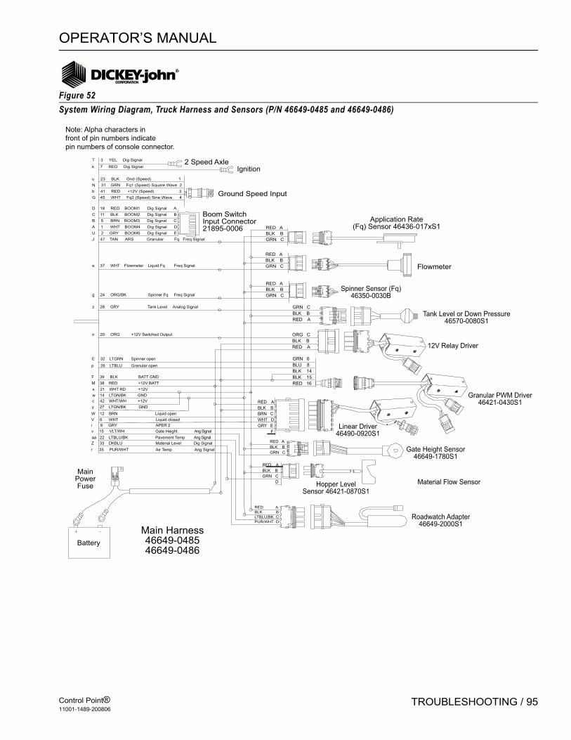
OPERATOR’S MANUAL
Control Point®11001-1489-200806
TROUBLESHOOTING / 95
Figure 52System Wiring Diagram, Truck Harness and Sensors (P/N 46649-0485 and 46649-0486)
Note: Alpha characters in
front of pin numbers indicate
pin numbers of console connector.
T 3 YEL Dig Signal
k 7 RED Dig Signal
u 23 BLK Gnd (Speed) 1
N 31 GRN Fq1 (Speed) Square Wave 2
b 41 RED +12V (Speed) 3
G 45 WHT Fq2 (Speed) Sine Wave 4
D 18 RED BOOM1 Dig Signal A
C 11 BLK BOOM2 Dig Signal B
B 5 BRN BOOM3 Dig Signal C
A 1 WHT BOOM4 Dig Signal D
U 2 GRY BOOM5 Dig Signal E
J 47 TAN ARS Granular Fq Freq Signal
2 Speed AxleIgnition
Ground Speed Input
Boom SwitchInput Connector21895-0006 RED A
BLK B
GRN C
Spinner Sensor (Fq)46350-0030B
Granular PWM Driver46421-0430S1
Linear Driver46490-0920S1
Hopper LevelSensor 46421-0870S1
GRN C
BLK B
RED A
RED A
BLK B
LTBLU/BK C
PUR/WHT D
Main Harness46649-048546649-0486
Battery
MainPowerFuse
Flowmeter
Application Rate(Fq) Sensor 46436-017xS1
e 37 WHT Flowmeter Liquid Fq Freq Signal
g 24 ORG/BK Spinner Fq Freq Signal
E 32 LTGRN Spinner open
p 26 LTBLU Granular open
n 20 ORG +12V Switched Output
r 35 PUR/WHT Air Temp Ang Signal
z 28 GRY Tank Level Analog Signal
F 39 BLK BATT GND
M 38 RED +12V BATT
x 21 WHT RD +12V
w 14 LTGN/BK GND
c 42 WHT/WH +12V
y 27 LTGN/BK GND
V 6 WHT Liquid closed
W 12 BRN Liquid open
i 9 GRY APER 2
v 15 VLT/WH Gate Height Ang Signal
aa 22 LTBLU/BK Pavement Temp Ang Signal
Z 33 DKBLU Material Level Dig Signal
Gate Height Sensor46649-1780S1
Material Flow Sensor
12V Relay Driver
Roadwatch Adapter46649-2000S1
Tank Level or Down Pressure46570-0080S1
RED A
BLK B
GRN C
RED A
BLK B
GRN C
ORG C
BLK B
RED A
GRN 6
BLU 8
BLK 14
BLK 15
RED 16
RED A
BLK B
GRN C
RED A
BLK B
GRN C
D
RED A
BLK B
BRN C
WHT D
GRY E
F
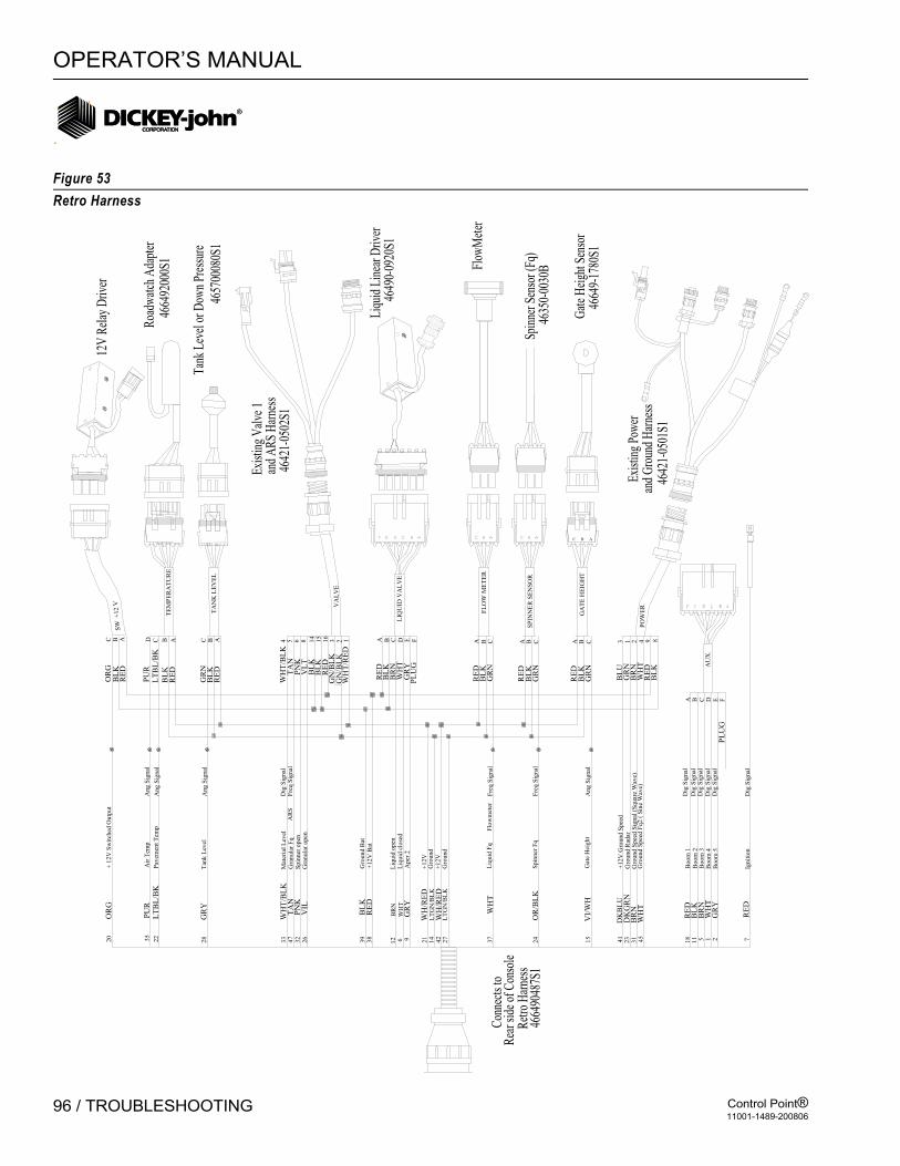
OPERATOR’S MANUAL
Control Point®11001-1489-200806
96 / TROUBLESHOOTING
Figure 53Retro Harness
Sp
inn
erop
en
Mat
eria
lL
evel
Gra
nula
rF
q
Gro
un
dB
at+
12
VB
at
Liq
uid
open
Liq
uid
clo
sed
Aper
2
Gra
nu
lar
open
Sp
inn
erF
q
Liq
uid
Fq
Gro
und
+12V
Gro
und
Gro
und
Spee
dF
q2
(S
ine
Wav
e)G
rou
nd
Sp
eed
Sig
nal
(Squar
eW
ave)
Gro
und
Rad
ar+
12V
Gro
und
Spee
d
Gat
eH
eig
ht
+12V
14
LT
GN
/BL
K
1W
HT
2 7
GR
Y
RE
D
18 511
RE
DB
LK
BR
NB
oo
m4
Ign
itio
n
Bo
om
5
Bo
om
3B
oo
m2
Bo
om
1
VI/
WH
DK
BL
UD
KG
RN
WH
TB
RN
41
23
31 45
15
WH
T
WH
/RE
DL
TG
N/B
LK
OR
/BL
K24
42
27
37
38
RE
D
WH
T
BR
N
WH
/RE
D
GR
Y9 21
12 639
BL
K
PN
K
WH
T/B
LK
47
32
33
26
TA
N
VIL
A CB ED FP
LU
G
AU
X.
WH
T
BL
UG
RN
BL
KR
ED
BR
N
GR
NB
LK
RE
D
GR
N
RE
DB
LK
BL
KG
RN
RE
D
PO
WE
R
13 2 4 9 8BA CG
AT
EH
EIG
HT
FL
OW
ME
TE
R
SP
INN
ER
SE
NS
OR
A CBB CA
WH
T/R
ED
GR
YP
LU
G
WH
T
RE
DB
LK
BR
N
GN
/BL
KG
N/B
LK
RE
DB
LK
BL
K
LIQ
UID
VA
LV
E
FEBA C D
VA
LV
E2 131
6
14
15
VL
T8
PN
K6
TA
N5
WH
T/B
LK
4
RE
DA
BL
KB
28
GR
YT
ank
Lev
elG
RN
C
RE
DA
BL
KB
22
LT
BL
/BK
Pav
emen
tT
emp
LT
BL
/BK
C
RE
DA
BL
KB
20
OR
G+
12
VS
wit
ched
Outp
ut
OR
GC
TA
NK
LE
VE
L
TE
MP
ER
AT
UR
E
SW
+12
V
35
PU
RA
irT
emp
PU
RD
Ang
Sig
nal
Ang
Sig
nal
Ang
Sig
nal
Ang
Sig
nal
Dig
Sig
nal
Dig
Sig
nal
Dig
Sig
nal
Dig
Sig
nal
Dig
Sig
nal
Dig
Sig
nal
Dig
Sig
nal
Fre
qS
ign
al
Fre
qS
ign
al
Fre
qS
ign
alA
RS
Flo
wm
eter
3
3
4
4

OPERATOR’S MANUAL
Control Point®11001-1489-200806
APPENDIX A CONVERTING CONSTANTS / 97
APPENDIX A CONVERTING CONSTANTS
FINE TUNING APPLICATION
Adjusting Granular ConstantsIf small (less than 10%) but consistent granular APR errors (either high or low) are observed over a period of time, fine tuning of the system can be performed by adjusting the value of the spreader constant by the same percentage as follows:
EXAMPLE: If SPR CON is 100 and Target APR is 300 LBS?MILE but Actual APR is known to be 315 LBS?MILE, adjust SPR CON using the above formula:
NOTE: Keyboard enter the new SPR CON on the appropriate (Granular) configuration screen.
Adjusting Liquid ConstantsIn a manner similar to that for granular (shown above,), liquid APR errors can be corrected by fine tuning the flowmeter constant (K-FACTOR) as follows:
EXAMPLE: If K-FACTOR is 1,000 and Target APR is 10 GAL?MILE, but Actual APR is known to be 9.5 GAL/MILE, adjust K-FACTOR using the above formula:
New SPR CON = Old SPR CON x Target APR
Actual APR
New SPR CON = 100 x = 95.2 300315
New K-FACTOR = Old K-FACTOR x Target APR
Actual APR
New K-FACTOR = 1000 x = 1053 10
9.5

OPERATOR’S MANUAL
Control Point®11001-1489-200806
98 / APPENDIX A CONVERTING CONSTANTS
CALCULATING SPREADER CONSTANTSThe spreader constant can be calculated if the following is known:
A = Number of pulses per revolution of the sensor shaft.B = Turns of the sensor shaft for each turn of the final shaft.C = Pounds of material discharged per revolution of the final shaft.
EXAMPLE:
A = 360 pulses per revolution (for Dj sensor p/n 46436-017X).B = 25 turns of the sensor shaft for each turn of the final shaft.C = 50 pounds of material discharged per revolution of final shaft.
NOTES:
1. V-Box spreaders have a different SPR CON for each gate setting.2. The number of pulses per revolution for several Dj shaft sensors are:
360 for p/n 46436-017X (standard Control Point® shaft sensor).60 for p/n 10844-000X900 for p/n 10837-00XX
SPR CON = Pulses Per PoundA x B
C
SPR CON = = 180 P/LB 360 x 25
50
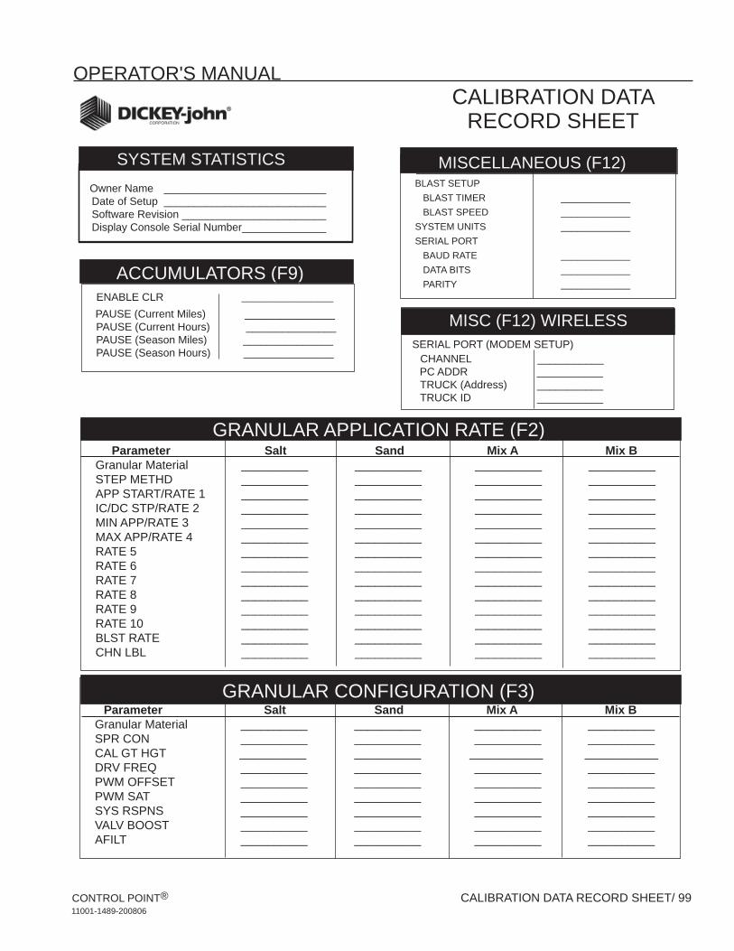
OPERATOR'S MANUAL
CONTROL POINT® CALIBRATION DATA RECORD SHEET/ 9911001-1489-200806
GRANULAR CONFIGURATION (F3) Parameter Salt Sand Mix A Mix B
Granular Material __________ __________ __________ __________SPR CON __________ __________ __________ __________ CAL GT HGT __________ __________ ___________ ___________DRV FREQ __________ __________ __________ __________PWM OFFSET __________ __________ __________ __________PWM SAT __________ __________ __________ __________SYS RSPNS __________ __________ __________ __________VALV BOOST __________ __________ __________ __________AFILT __________ __________ __________ __________
GRANULAR APPLICATION RATE (F2) Parameter Salt Sand Mix A Mix B
Granular Material __________ __________ __________ __________STEP METHD __________ __________ __________ __________APP START/RATE 1 __________ __________ __________ __________IC/DC STP/RATE 2 __________ __________ __________ __________MIN APP/RATE 3 __________ __________ __________ __________MAX APP/RATE 4 __________ __________ __________ __________RATE 5 __________ __________ __________ __________RATE 6 __________ __________ __________ __________RATE 7 __________ __________ __________ __________RATE 8 __________ __________ __________ __________RATE 9 __________ __________ __________ __________RATE 10 __________ __________ __________ __________BLST RATE __________ __________ __________ __________CHN LBL __________ __________ __________ __________
MISCELLANEOUS (F12) BLAST SETUP BLAST TIMER _____________ BLAST SPEED _____________SYSTEM UNITS _____________SERIAL PORT BAUD RATE _____________ DATA BITS _____________ PARITY _____________
ENABLE CLR _________________
PAUSE (Current Miles) _______________ PAUSE (Current Hours) _______________ PAUSE (Season Miles) _______________ PAUSE (Season Hours) _______________
Owner Name ___________________________ Date of Setup ___________________________ Software Revision ________________________ Display Console Serial Number ______________
SYSTEM STATISTICS
ACCUMULATORS (F9)
MISCELLANEOUS (F12)
GRANULAR APPLICATION RATE (F2)
GRANULAR CONFIGURATION (F3)
SYSTEM INFORMATION (F9) SERIAL PORT (MODEM SETUP) CHANNEL ___________ PC ADDR ___________ TRUCK (Address) ___________ TRUCK ID ___________
MISC (F12) WIRELESS
CALIBRATION DATA RECORD SHEET

OPERATOR'S MANUAL
100/CALIBRATION DATA RECORD SHEET CONTROL POINT® 11001-1489-200806
CALIBRATION DATA RECORD SHEET
Parameter Salt Sand Mix A Mix BGranular Material __________ __________ __________ __________STEP METHD __________ __________ __________ __________ APP START/RATE 1 __________ __________ __________ __________IC/DC STP/RATE 2 __________ __________ __________ __________MIN APP/RATE 3 __________ __________ __________ __________MAX APP/RATE 4 __________ __________ __________ __________RATE 5 __________ __________ __________ __________RATE 6 __________ __________ __________ __________RATE 7 __________ __________ __________ __________RATE 8 __________ __________ __________ __________RATE 9 __________ __________ __________ __________RATE 10 __________ __________ __________ __________BLST RATE __________ __________ __________ __________CHN LBL __________ __________ __________ __________
GRANULAR APPLICATION RATE (F2) Parameter Liquid 1 Liquid 2 Liquid 3 Liquid 4 Liquid Material
K-FACTOR/DENSITY __________ __________ __________ __________DRV FREQ __________ __________ __________ __________PWM OFFSET __________ __________ __________ __________PWM SAT. __________ __________ __________ __________SYS RSPNS __________ __________ __________ __________VALV BOOST __________ __________ __________ __________AFILT __________ __________ __________ __________TANK LEVEL __________ __________ __________ __________VALVE LOCK __________ __________ __________ __________Boom SECN ENBLED __________ __________ __________ __________ 12V ON __________ __________ __________ __________ NUM OF NZZLS __________ __________ __________ __________ NZZLE SPCNG __________ __________ __________ __________ PAUSE ENABLE __________ __________ __________ __________ BOOM INPUT __________ __________ __________ __________
MISCELLANEOUS (F12) UNLOAD _____________NO GND SPD _____________DRV FREQ _____________PULSE FDBK _____________PWM OFFSET _____________PWM SAT _____________GSRS ENABLE _____________
SPINNER CONFIGURATION (F8)
LIQUID CONFIGURATION (F5)
LIQUID APPLICATION RATE (F4)
MISCELLANEOUS (F12)
MAX SPEED __________MANUAL ON ___________MANUAL DRIVER __________MANUAL SPEED __________START UP __________SHUT OFF SPD ___________2 AXLES ___________
GROUND SPEED CONFIGURATION (F7)
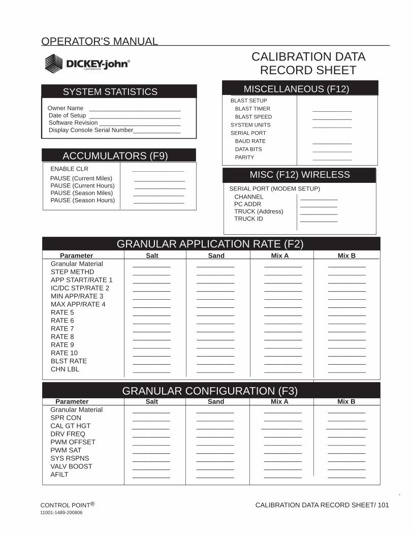
OPERATOR'S MANUAL
CONTROL POINT® CALIBRATION DATA RECORD SHEET/ 10111001-1489-200806
GRANULAR CONFIGURATION (F3) Parameter Salt Sand Mix A Mix B
Granular Material __________ __________ __________ __________SPR CON __________ __________ __________ __________ CAL GT HGT __________ __________ ___________ ___________DRV FREQ __________ __________ __________ __________PWM OFFSET __________ __________ __________ __________PWM SAT __________ __________ __________ __________SYS RSPNS __________ __________ __________ __________VALV BOOST __________ __________ __________ __________AFILT __________ __________ __________ __________
GRANULAR APPLICATION RATE (F2) Parameter Salt Sand Mix A Mix B
Granular Material __________ __________ __________ __________STEP METHD __________ __________ __________ __________APP START/RATE 1 __________ __________ __________ __________IC/DC STP/RATE 2 __________ __________ __________ __________MIN APP/RATE 3 __________ __________ __________ __________MAX APP/RATE 4 __________ __________ __________ __________RATE 5 __________ __________ __________ __________RATE 6 __________ __________ __________ __________RATE 7 __________ __________ __________ __________RATE 8 __________ __________ __________ __________RATE 9 __________ __________ __________ __________RATE 10 __________ __________ __________ __________BLST RATE __________ __________ __________ __________CHN LBL __________ __________ __________ __________
MISCELLANEOUS (F12) BLAST SETUP BLAST TIMER _____________ BLAST SPEED _____________SYSTEM UNITS _____________SERIAL PORT BAUD RATE _____________ DATA BITS _____________ PARITY _____________
ENABLE CLR _________________
PAUSE (Current Miles) _______________ PAUSE (Current Hours) _______________ PAUSE (Season Miles) _______________ PAUSE (Season Hours) _______________
Owner Name ___________________________ Date of Setup ___________________________ Software Revision ________________________ Display Console Serial Number ______________
SYSTEM STATISTICS
ACCUMULATORS (F9)
MISCELLANEOUS (F12)
GRANULAR APPLICATION RATE (F2)
GRANULAR CONFIGURATION (F3)
SERIAL PORT (MODEM SETUP) CHANNEL ___________ PC ADDR ___________ TRUCK (Address) ___________ TRUCK ID ___________
MISC (F12) WIRELESS
CALIBRATION DATA RECORD SHEET

OPERATOR'S MANUAL
102/CALIBRATION DATA RECORD SHEET CONTROL POINT® 11001-1489-200806
CALIBRATION DATA RECORD SHEET
Parameter Salt Sand Mix A Mix BGranular Material __________ __________ __________ __________STEP METHD __________ __________ __________ __________ APP START/RATE 1 __________ __________ __________ __________IC/DC STP/RATE 2 __________ __________ __________ __________MIN APP/RATE 3 __________ __________ __________ __________MAX APP/RATE 4 __________ __________ __________ __________RATE 5 __________ __________ __________ __________RATE 6 __________ __________ __________ __________RATE 7 __________ __________ __________ __________RATE 8 __________ __________ __________ __________RATE 9 __________ __________ __________ __________RATE 10 __________ __________ __________ __________BLST RATE __________ __________ __________ __________CHN LBL __________ __________ __________ __________
GRANULAR APPLICATION RATE (F2) Parameter Liquid 1 Liquid 2 Liquid 3 Liquid 4 Liquid Material
K-FACTOR/DENSITY __________ __________ __________ __________DRV FREQ __________ __________ __________ __________PWM OFFSET __________ __________ __________ __________PWM SAT. __________ __________ __________ __________SYS RSPNS __________ __________ __________ __________VALV BOOST __________ __________ __________ __________AFILT __________ __________ __________ __________TANK LEVEL __________ __________ __________ __________VALVE LOCK __________ __________ __________ __________Boom SECN ENBLED __________ __________ __________ __________ 12V ON __________ __________ __________ __________ NUM OF NZZLS __________ __________ __________ __________ NZZLE SPCNG __________ __________ __________ __________ PAUSE ENABLE __________ __________ __________ __________ BOOM INPUT __________ __________ __________ __________
MISCELLANEOUS (F12) UNLOAD _____________NO GND SPD _____________DRV FREQ _____________PULSE FDBK _____________PWM OFFSET _____________PWM SAT _____________GSRS ENABLE _____________
SPINNER CONFIGURATION (F8)
LIQUID CONFIGURATION (F5)
LIQUID APPLICATION RATE (F4)
MISCELLANEOUS (F12)
MAX SPEED __________MANUAL ON __________MANUAL DRIVER __________MANUAL SPEED __________START UP __________SHUT OFF SPD __________2 AXLES __________CONSTANT __________
GROUND SPEED CONFIGURATION (F7)

Copyright 2008 DICKEY-john Corporation Specifications subject to change without notice.
Dealers have the responsibility of calling to the attention of their customers the following warranty prior to acceptance of an order from their customer for any DICKEY-john product.
DICKEY-john® WARRANTY DICKEY-john warrants to the original purchaser for use that, if any part of the product
proves to be defective in material or workmanship within one year from date of original
installation, and is returned to DICKEY-john within 30 days after such defect is discovered,
DICKEY-john will (at our option) either replace or repair said part. This warranty does not apply
to damage resulting from misuse, neglect, accident, or improper installation or maintenance; any
expenses or liability for repairs made by outside parties without DICKEY-john’s written consent;
damage to any associated equipment; or lost profits or special damages. Said part will not be
considered defective if it substantially fulfills the performance expectations. THE FOREGOING
WARRANTY IS EXCLUSIVE AND IN LIEU OF ALL OTHER WARRANTIES OF
MERCHANTABILITY, FITNESS FOR PURPOSE, AND OF ANY OTHER TYPE, WHETHER
EXPRESS OR IMPLIED. DICKEY-john neither assumes nor authorizes anyone to assume for it
any other obligation or liability in connection with said part and will not be liable for
consequential damages. Purchaser accepts these terms and warranty limitations unless the
product is returned within fifteen days for full refund of purchase price.
For DICKEY- john Service Department, call 1-800-637-3302 in either the U.S.A. or Canada
Headquarters: 5200 Dickey-john Road, Auburn, IL USA 62615 TEL: 217 438 3371, FAX: 217 438 6012, WEB: www.dickey-john.com Europe: DICKEY-john Europe S.A.S, 165, boulevard de Valmy, 92706 – Colombes – France TEL: 33 (0) 1 41 19 21 80, FAX: 33 (0) 1 47 86 00 07 WEB: www.dickey-john.eu