operators manual for sea tel dac-2302 … · configuring the comm if ports of the dac-2202 acu ......
TRANSCRIPT

Sea Tel, Inc. 4030 Nelson Avenue Concord, CA 94520 Tel: (925) 798-7979 Fax: (925) 798-7986 Web: : www.cobham.com\seatel
Sea Tel Europe Unit 1, Orion Industrial Centre Wide Lane, Swaythling Southampton, UK S0 18 2HJ Tel: 44 (0)23 80 671155 Fax: 44 (0)23 80 671166 Web: www.cobham.com\seatel
Sea Tel Inc doing business as Cobham SATCOM
April 21, 2011 Document. No. 132628 Revision B
OPERATORS MANUAL
FOR SEA TEL DAC-2302 ANTENNA CONTROL UNIT
Antenna Serial Number: ________________________________
DAC-2302 Serial Number: _______________________________
ii
These commodities, technology or software were exported from the United States in accordance with the Export Administration Regulations. Diversion contrary to U.S. law is prohibited.
Sea Tel Marine Stabilized Antenna systems are manufactured in the United States of America.
Sea Tel is an ISO 9001:2008 registered company.
Certificate Number 13690 issued March 14, 2011.
R&TTE
CE
The Sea Tel DAC-2202, or DAC-2302, Antenna Control Unit used with the Sea Tel Antenna complies with the requirements for Radio and Telecommunication Terminal Equipment. A copy of the R&TTE Declaration of Conformity for this equipment is contained in the Antenna Manual for your system.
The Sea Tel DAC-2202, or DAC-2302, Antenna Control Unit contains FCC compliant supervisory software to continuously monitor the pedestal pointing accuracy and use it to control the “Transmit Mute” function of the satellite modem to satisfy the provisions of FCC 47 C.F.R. § 25.222(a)(l)(iii). A copy of the FCC Declaration of Conformity for this equipment is contained in the Antenna Manual for your system.
Copyright Notice
All Rights Reserved. The information contained in this document is proprietary to Sea Tel, Inc.. This document may not be reproduced or distributed in any form without prior consent of Sea Tel, Inc. The information in this document is subject to change without notice. Copyright © 2010 Sea Tel, Inc is doing business as Cobham SATCOM.
This document has been registered with the U.S. Copyright Office.
Revision History
REV ECO# Date Description By
A N/A June 30, 2010 PRELIMINARY Release. ECM
B N/A April 21, 2011 Updated text to include GSR4 software functions and added Setup – CommIF and HTML Pages chapter
MDN

Table of Contents DAC2302 Operator Manual
iii
1. QUICK START OPERATION – INTRODUCTION ...................................................................................................................... 1-1 1.1. QUICK START OPERATION ........................................................................................................................................................................... 1-1 1.2. FRONT PANEL LAYOUT .................................................................................................................................................................................. 1-1 1.3. BASIC FUNCTION OF FRONT PANEL KEYS ................................................................................................................................................. 1-2 1.4. BASIC DESCRIPTION OF FRONT PANEL KEYS AND THEIR FUNCTIONS ................................................................................................... 1-2 1.5. BASIC DESCRIPTION OF FRONT PANEL STATUS LEDS ........................................................................................................................... 1-3
2. OPERATION ..................................................................................................................................................................................................... 2-1 2.1.1. SHIP information menu. ........................................................................................................................................................ 2-1 2.1.2. SAT information menus. ......................................................................................................................................................... 2-3 2.1.3. ANTENNA information menus. ........................................................................................................................................... 2-7 2.1.4. Mode-Control and Status Menus. ..................................................................................................................................... 2-9 2.1.5. SETUP Parameter display and entry menus. ............................................................................................................ 2-10
2.2. TRACKING OPERATION ............................................................................................................................................................................... 2-10 2.2.1. DishScan Operation ............................................................................................................................................................... 2-11
2.1. SEARCHING OPERATION ............................................................................................................................................................................. 2-11 2.1.1. Default Standard (Box) Search Pattern ....................................................................................................................... 2-11 2.1.2. Inclined Orbit Search Pattern .......................................................................................................................................... 2-12 2.1.3. No Gyro Search Pattern ...................................................................................................................................................... 2-13
2.2. AUTO-POLARIZATION OPERATION........................................................................................................................................................... 2-14 2.3. RADOME ASSEMBLY OPERATION .............................................................................................................................................................. 2-14
3. SETUP – COMMIF AND HTML PAGES ........................................................................................................................................... 3-1 3.1. CONFIGURING THE COMM IF PORTS OF THE DAC-2202 ACU ....................................................................................................... 3-1 3.2. INTERNAL HTML PAGE ................................................................................................................................................................................ 3-3 3.3. SYSTEM INFORMATION ................................................................................................................................................................................ 3-4 3.4. COMMUNICATION PORT SETTINGS ........................................................................................................................................................... 3-5 3.5. DAC PARAMETERS PAGE 1 .......................................................................................................................................................................... 3-7 3.6. DAC PARAMETERS PAGE 2 .......................................................................................................................................................................... 3-8 3.7. STATUS PAGE ................................................................................................................................................................................................. 3-9 3.8. FAVORITE SATELLITES PAGE ...................................................................................................................................................................... 3-10

DAC2302 Operator Manual Table of Contents
iv
This Page Intentionally Left Blank
Quick Start Operation – Introduction DAC2302 Operator Manual
1-1
1. Quick Start Operation – Introduction When power is turned ON, the ACU Display will initially show “SEA TEL INC - MASTER” and the ACU software version (ie DAC-2302 VER 7.xx ). 10 seconds later, the display will switch to “SEA TEL INC - REMOTE” and “INITIALIZING” for approximately two minutes while the Pedestal Control Unit (PCU) completes initialization of the antenna pedestal and then reports its Model & Software version.
1.1. Quick Start Operation If your system has been set up correctly and the ship has not moved since the system was used last. Operation of the system from a cold start involves the following steps.
1. Turn on the AC power switches for the Antenna Control Unit (ACU) and other Below Decks Equipment..
2. Press the SHIP key to display and check the vessels Latitude, Longitude and Heading values. Latitude and Longitude should still be correct, but may be updated if necessary. Heading, in some cases, will be 000.0 and you will have to enter the initial value of the ships current heading. Entry of ships heading is not required when your system is connected to a 1:1 Synchro or NMEA 0183 Heading Gyro Compass output. To correct the Heading value, press the SHIP key 3 times to select ship's heading (HDG) entry mode. Using the numeric key pad, enter in the vessel’s current heading position and then ENTER to submit the value. Press the SHIP key again to return to the full Ship’s display main menu.
3. If setup correctly, the ACU should automatically target the last satellite that was used. If it does not, press SAT key twice to display the Satellite display sub-menu so you can manually target the satellite. Enter in the satellite’s longitude position and then press ENTER. If you are targeting a different satellite you will need to change the tracking parameters and then target the desired satellite, refer to the operation section for the Satellite menu below.
A. If no signal is found: The Tracking LED will flash for a short period of time (per the SEARCH DELAY parameter) followed by the Search LED coming ON. The ACU will automatically move the antenna in a spiral SEARCH pattern until the ACU receives a signal (AGC) value that is greater than the threshold value. Tracking will take over (Tracking LED ON) and automatically peak the antenna position for highest receive signal level from the satellite which has been acquired.
B. If satellite signal is found AND network lock is achieved: The received signal level (AGC) will be higher than the threshold value. Tracking will take over (Tracking LED ON) and automatically peak the antenna position for highest receive signal level from the satellite and the satellite modem will get modem lock/receive sync. When the ACU has signal above threshold AND modem has network lock the antenna will continue to track the satellite.
B. If satellite signal is found but network lock is NOT achieved: If you’re system has been setup to use the network lock/satellite ID output from the satellite modem; When signal above threshold is found but the modem does NOT get network lock (receive sync), the ACU will re-target in an attempt to find the satellite which has signal AND network lock. This could be due to the antenna targeting the wrong satellite, polarization failure, modem failure (not getting receive sync) or network failure (not allowing the modem to get receive sync). The ACU will continue to re-target.
Upon completion of the above, the system will continue to operate automatically indefinitely until; AC power to the system is interrupted OR The satellite signal is blocked OR The ship sails into an area of insufficient satellite signal level.
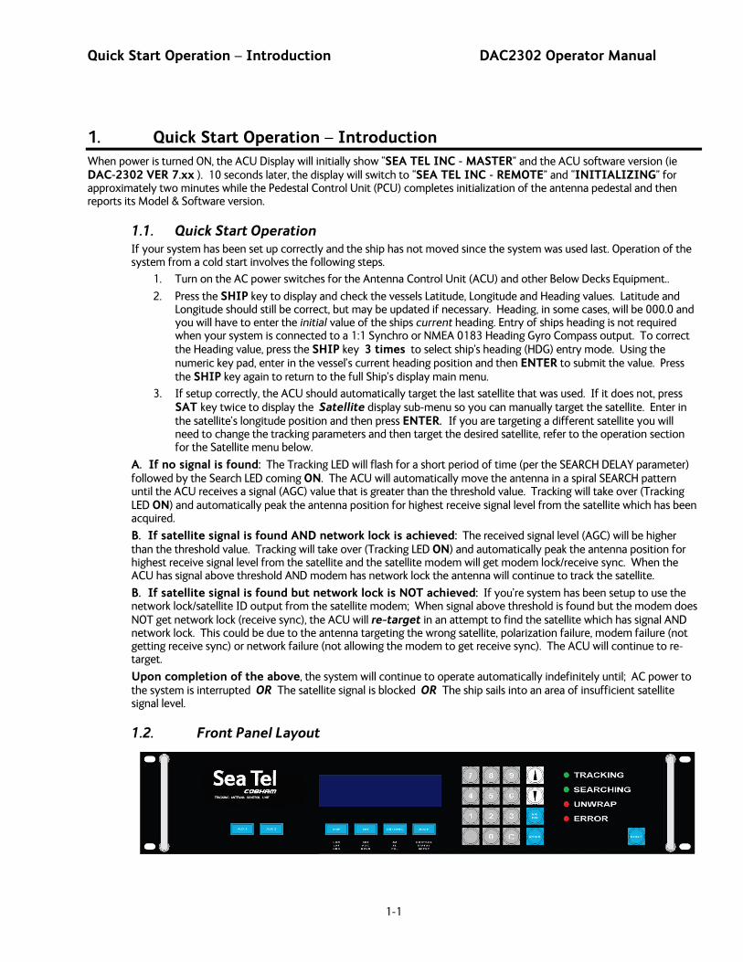
1.2. Front Panel Layout
DAC2302 Operator Manual Quick Start Operation – Introduction
1-2
1.3. Basic Function of Front Panel Keys Keyboard operation is very simple and straightforward. Basic function of each key is:
1.4. Basic description of front panel keys and their functions The basic functions of the front panel keys, display and LEDs are:
DISPLAY - 20 character x 2-line display of all menu display, entry, control and status windows.
AUX1 - Toggles Tracking ON/OFF, regardless of which displayed menu location you are currently in.
AUX2 - No current operator function.
Main Menu Display & Entry Keys:
SHIP - Accesses the SHIP menus to display, enter or edit current Ships’ Latitude, Longitude and gyro compass Heading information.
SAT - Accesses the SAT menus to display, enter or edit current Satellite Longitude, Threshold, Satellite ID Tracking Receiver settings, Network ID and current signal level being received (AGC).
ANTENNA - Accesses the ANTENNA menus to display, enter or edit current Azimuth, Elevation & Relative antenna position and Polarization setting. Current signal level being received (AGC) and Conscan tracking signals are also displayed in some of the sub-menu screens.
MODE - Accesses control of Tracking band & ON/OFF selection, Searching ON/OFF selection, Error status and Remote Auxiliary value.
NUMERIC KEY PAD - Used to key in numeric values in all entry menus.
NUMBERS - Key in numeric value of desired entry. May be used in conjunction with the Decimal Point.
DECIMAL POINT - Used with the Numbers to enter whole and tenths of degrees or MHz & KHz to enter tuning frequency.
C Key - Clear an incorrect numeric entry.
Special Keys -
UP Arrow - Steps the selected entry UP one increment per sequential key-press or rapidly increments the selected entry when pressed & held. Affects all Numeric entries and is used to toggle Tracking ON/OFF, turn Searching ON or to clear the Error display.
DOWN Arrow - Steps the selected entry DOWN one increment per sequential key-press or rapidly increments the selected entry when pressed & held. Affects all Numeric entries and is used to toggle Tracking Band selection, turn Searching OFF or to clear the Error display.
N/S/E/W - Toggles North/South Latitude entry, East/West Longitude entry, Tracking Receiver Input selection and Polarization mode (depends on POL TYPE parameter setting). It is used to make numeric entries to cause them to become negative values. When in MODE menus the N/S/E/W key steps the display back UP to the previous sub-menu.
ENTER - Enters the value that has been keyed in.
RESET - Resets the processors inside the ACU. This does NOT reset the antenna pedestal.
Quick Start Operation – Introduction DAC2302 Operator Manual
1-3
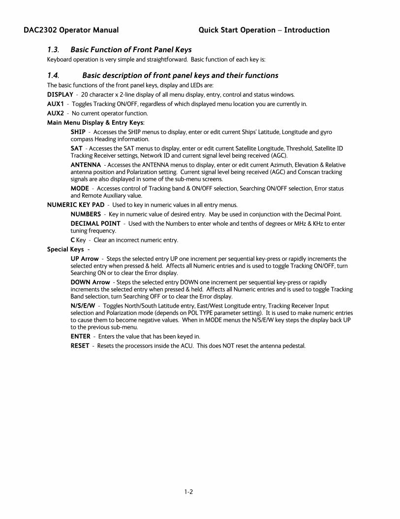
1.5. Basic Description of Front Panel Status LEDs
TRACKING - (Green LED)
ON indicates that the ACU is Tracking a satellite signal whose AGC value is greater than the Threshold value AND contains the desired Network ID. The ACU is actively issuing small azimuth & elevation position adjustments to the antenna to optimize the signal level (AGC). If the system was Searching, SEARCH will go OFF when TRACKING turns ON.
Blinking indicates that the satellite signal AGC value is less than the Threshold value, OR is not the desired Network ID, and the ACU is counting down “SEARCH DELAY” (seconds). If the AGC does not rise above the Threshold before the count-down is completed, the ACU will automatically start, or continue, a SEARCH to acquire a signal that is greater than Threshold AND contains the desired NID. When SEARCH is ON, TRACKING will be OFF.
OFF indicates that Tracking is OFF. This may be due to the operator turning Tracking OFF intentionally or that Tracking was pre-empted by SEARCH.
NOTE: In NBIF mode the tracking LED will go OFF for several seconds once every 2 minutes while AFC is adjusting the frequency.
SEARCHING - (Green LED)
ON indicates that the ACU is Searching for a satellite signal whose AGC value is greater than the Threshold value. When a satellite signal is found SEARCH will go OFF and TRACKING will come ON. If an adequate satellite signal is not found during the Search, SEARCH will blink as the antenna re-targets to the desired satellite. If an adequate satellite signal is still not found, then TRACKING will begin flashing (count-down) until the next SEARCH is automatically started.
Blinking indicates that the antenna is TARGETING to the calculated Azimuth & Elevation positions of the desired satellite (SAT). When the antenna arrives at the calculated position SEARCH will go OFF. If an adequate satellite signal is found at the targeted position Tracking will commence. If an adequate satellite signal is not found at the targeted position, TRACKING will begin blinking (see above) until the next SEARCH is automatically started.
OFF indicates that SEARCH is OFF. This may be due to the operator turning Search OFF intentionally or that Tracking has pre-empted SEARCH.
UNWRAP - (Red LED) Your system does not require UNWRAP, therefore, this LED should never be ON.
ERROR - (Red LED)
ON indicates that one, or more, discrete system errors have occurred. Refer to MODE information menus below to determine which error(s) have occurred.
OFF indicates that no errors have occurred.
Status LED’s

DAC2302 Operator Manual Quick Start Operation – Introduction
1-4
This Page Intentionally Left Blank
Operation DAC2302 Operator Manual
2-1
2. Operation
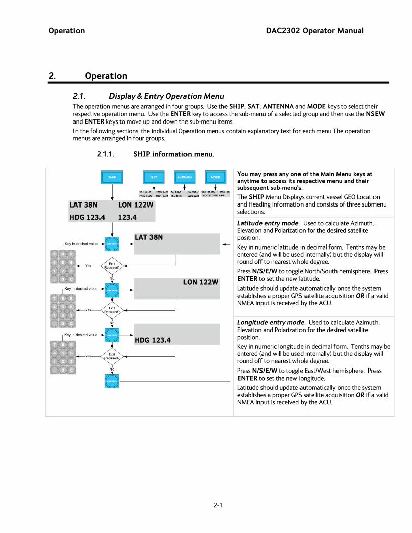
2.1. Display & Entry Operation Menu The operation menus are arranged in four groups. Use the SHIP, SAT, ANTENNA and MODE keys to select their respective operation menu. Use the ENTER key to access the sub-menu of a selected group and then use the NSEW and ENTER keys to move up and down the sub-menu items.
In the following sections, the individual Operation menus contain explanatory text for each menu The operation menus are arranged in four groups.
2.1.1.
SHIP information menu.
You may press any one of the Main Menu keys at anytime to access its respective menu and their subsequent sub-menu’s.
The SHIP Menu Displays current vessel GEO Location and Heading information and consists of three submenu selections.
Latitude entry mode. Used to calculate Azimuth, Elevation and Polarization for the desired satellite position.
Key in numeric latitude in decimal form. Tenths may be entered (and will be used internally) but the display will round off to nearest whole degree.
Press N/S/E/W to toggle North/South hemisphere. Press ENTER to set the new latitude.
Latitude should update automatically once the system establishes a proper GPS satellite acquisition OR if a valid NMEA input is received by the ACU.
Longitude entry mode. Used to calculate Azimuth, Elevation and Polarization for the desired satellite position.
Key in numeric longitude in decimal form. Tenths may be entered (and will be used internally) but the display will round off to nearest whole degree.
Press N/S/E/W to toggle East/West hemisphere. Press ENTER to set the new longitude.
Latitude should update automatically once the system establishes a proper GPS satellite acquisition OR if a valid NMEA input is received by the ACU.

DAC2302 Operator Manual Operation
2-2
Heading entry mode. Used to provide “True” Azimuth antenna position.
If the GYRO TYPE parameter is NMEA0183 data or 1:1 Synchro, you will not be able to set HDG to any other value than it receives from the Ships Gyro Compass. For all other acceptable Gyro Compass input types the HDG MUST be initially set whenever the ACU power is turned ON. Key in the heading value of the Ships Gyro Compass and press ENTER.
HDG display may be a single value, or left and right values depending on the GYRO TYPE parameter. When Left and right values are displayed, left is the response from the pedestal and right in the local input from the gyrocompass.
During subsequent normal operation, the HDG value should automatically follow the Ships Gyro Compass correctly (HDG value should agree with the value observed on the Gyro Compass).

Operation DAC2302 Operator Manual
2-3
2.1.2.
SAT information menus.
You may press any one of the Main Menu keys at anytime to access its respective menu and their subsequent sub-menu’s
The SAT Menu displays the current SAT and Signal Level information and consists of eight submenu selections.
The NID displayed (while in full menu view) is the Network ID that is currently being received from the satellite that the antenna is currently pointed at. This Received NID must match the Target NID (if set to any value other than 0000) else, the ACU will
Satellite Longitude entry mode. Press ENTER from the SAT main menu to access the Satellite Sub Menu. Used to calculate antenna Elevation, Azimuth and Polarity pointing angles.
issue a satellite target command. It should also be noted that the system will not be able to decode the downstream NID unless all of the other tracking receiver parameters are set correctly (i.e. Freq, Baud, Tone, FEC, etc).
Key in the numeric longitude of the satellite you want to target (even if it is the same value as is presently displayed), press N/S/E/W to toggle the E/W hemisphere as necessary and then press ENTER.
Threshold entry mode. Press ENTER from the SAT Sub menu to access the Threshold Sub Menu. Threshold represents the minimum AGC value required to enable an active Tracking status. If the factory default setup, Automatic Threshold is enabled, the Threshold value (nnnn counts of AGC) will automatically be set by the ACU. However if you wish to manually set threshold; Note the Peak “on satellite” AGC value, move AZ or EL and note the “off satellite” (Noise Floor) AGC value. Calculate the difference between Peak AGC and Noise Floor AGC. Threshold should be set to 1/3 (to ½) of the Difference above Noise Floor. Key in the desired numeric value and press ENTER.
DAC2302 Operator Manual Operation
2-4
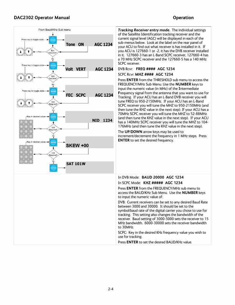
Tracking Receiver entry mode. The individual settings of the Satellite Identification tracking receiver and the current signal level (AGC) will be displayed in each of the sub-menus below. Look at the label on the rear panel of your ACU to find out what receiver is has installed in it. If you ACU is 127660-1 or -2, it has the DVB receiver installed in it. 127660-3 has an L-Band SCPC receiver, 127660-4 has a 70 MHz SCPC receiver and the 127660-5 has a 140 MHz SCPC receiver.
DVB Rcvr: FREQ #### AGC 1234
SCPC Rcvr: MHZ #### AGC 1234
Press ENTER from the THRESHOLD sub menu to access the FREQUENCY/MHz Sub Menu. Use the NUMBER keys to input the numeric value (in MHz) of the Intermediate Frequency signal from the antenna that you want to use for Tracking. If your ACU has an L-Band DVB receiver you will tune FREQ to 950-2150MHz. If your ACU has an L-Band SCPC receiver you will tune the MHZ to 950-2150MHz (and then tune the KHZ value in the next step). If your ACU has a 70MHz SCPC receiver you will tune the MHZ to 52-88MHz (and then tune the KHZ value in the next step). If your ACU has a 140MHz SCPC receiver you will tune the MHZ to 104-176MHz (and then tune the KHZ value in the next step).
The UP/DOWN arrow keys may be used to increment/decrement the frequency in 1 MHz steps. Press ENTER to set the desired frequency.
In DVB Mode: BAUD 20000 AGC 1234
In SCPC Mode: KHZ ##### AGC 1234
Press ENTER from the FREQUENCY/MHz sub menu to access the BAUD/KHz Sub Menu. Use the NUMBER keys to input the numeric value of:
DVB: Current receivers can be set to any desired Baud Rate between 3000 and 30000. It should be set to the symbol/baud rate of the digital carrier you chose to use for tracking. This setting also changes the bandwidth of the receiver. Baud setting of 3000-5000 sets the receiver to 15 MHz bandwidth. 6000-30000 sets the receiver bandwidth to 30MHz.
SCPC: Key in the desired KHz frequency value you wish to use for tracking.
Press ENTER to set the desired BAUD/KHz value.
Operation DAC2302 Operator Manual
2-5
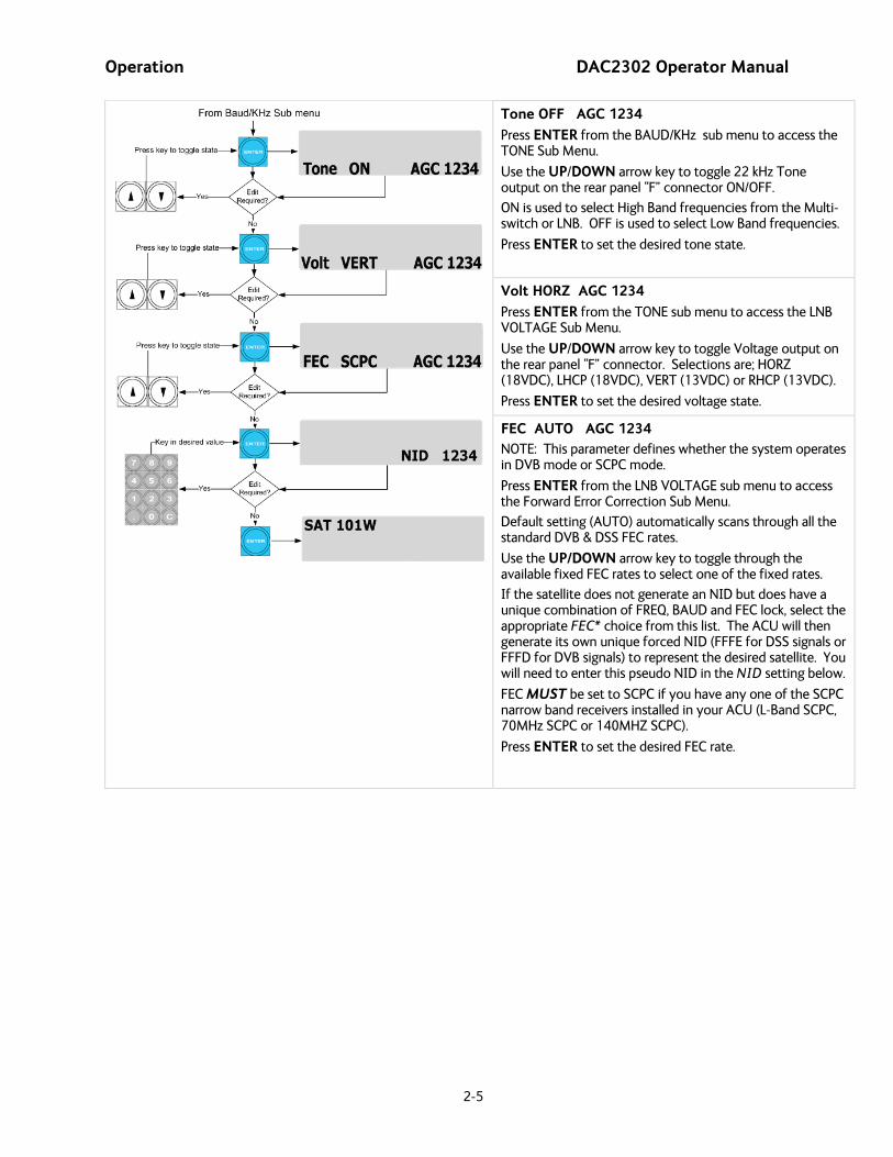
Tone OFF AGC 1234
Press ENTER from the BAUD/KHz sub menu to access the TONE Sub Menu.
Use the UP/DOWN arrow key to toggle 22 kHz Tone output on the rear panel “F” connector ON/OFF.
ON is used to select High Band frequencies from the Multi-switch or LNB. OFF is used to select Low Band frequencies.
Press ENTER to set the desired tone state.
Volt HORZ AGC 1234
Press ENTER from the TONE sub menu to access the LNB VOLTAGE Sub Menu.
Use the UP/DOWN arrow key to toggle Voltage output on the rear panel “F” connector. Selections are; HORZ (18VDC), LHCP (18VDC), VERT (13VDC) or RHCP (13VDC).
Press ENTER to set the desired voltage state.
FEC AUTO AGC 1234 NOTE: This parameter defines whether the system operates in DVB mode or SCPC mode.
Press ENTER from the LNB VOLTAGE sub menu to access the Forward Error Correction Sub Menu.
Default setting (AUTO) automatically scans through all the standard DVB & DSS FEC rates.
Use the UP/DOWN arrow key to toggle through the available fixed FEC rates to select one of the fixed rates.
If the satellite does not generate an NID but does have a unique combination of FREQ, BAUD and FEC lock, select the appropriate FEC* choice from this list. The ACU will then generate its own unique forced NID (FFFE for DSS signals or FFFD for DVB signals) to represent the desired satellite. You will need to enter this pseudo NID in the NID setting below.
FEC MUST be set to SCPC if you have any one of the SCPC narrow band receivers installed in your ACU (L-Band SCPC, 70MHz SCPC or 140MHZ SCPC).
Press ENTER to set the desired FEC rate.

DAC2302 Operator Manual Operation
2-6
NID #### AGC 1234
Press ENTER from the Forward Error Correction sub menu to access the Network ID Sub Menu.
Used to enter the NID (or forced NID) of the satellite you want to The Network ID is a four digit HEX value. Enter 0000 if no NID is available, or to test for proper FREQ, BAUD & FEC settings. NID MUST be set to 0000 whenever there is not a valid four digit hex number in the digital data stream, you do not want to use an NID OR you are using an external (AGC-GND) input from a satellite modem or receiver.
Use the appropriate NUMBER key to enter a numeric value.
Use a two key sequence (decimal point followed by a number key) to enter an alpha character (A - I).1 = A, .2 = B, .3 = C, .4 = D, .5 = E, .6 = F
.7 = G, .8 = H, .9 = I
Example: to enter an NID of 1B3D you would key in “ 1, ., 2, 3, ., 4 “. That’s the number one, decimal point, the number two, the number three, decimal point, the number four.
NOTE: Most reference sites lists a satellite’s NID in decimal format, the Tracking Receiver requires a four digit HEX Value entry.
Example: A decimal NID value of 4100 would be entered as HEX NID value 1004.
Press ENTER to set the desired NID.
The ACU will automatically send a satellite target command to the antenna if the decoded (received) NID does not exactly
SKEW +00 AGC 1234
match the Target NID entered in this step, even if tracking the correct satellite with the AGC signal level above the set AGC threshold.
Press ENTER from the Network ID sub menu to access the Sat Skew Menu.
Used to add or subtract additional Polarization Skew for a particular satellite when known.
Skew should only be entered when the transmission signals from a satellite is intentionally skewed from pure Vertical or Horizontal. Refer to the POL OFFSET parameter for calibrating your antennas linear feed assembly

Operation DAC2302 Operator Manual
2-7
2.1.3.
ANTENNA information menus.
You may press any one of the Main Menu keys at anytime to access its respective menu and their subsequent sub-menu’s
The ANTENNA Menu displays current pointing & polarization angles of the Antenna and consists of four submenu selections.
NOTE: If your system has not been properly calibrated, the displayed values may not correctly reflect the actual mechanical angle of the antenna.
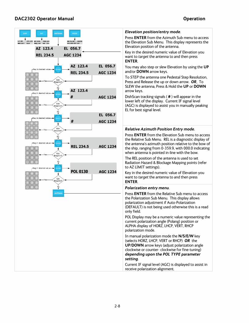
Azimuth position/entry mode.
Press ENTER from the ANTENNA main menu to access the Azimuth Sub Menu. This display represents the True North Azimuth position of the antenna. This value is the sum of ships heading (HDG), antenna relative (REL) position and your Azimuth Trim Parameter.
(AZ=HDG+REL+AZ TRIM, If AZ>360 the display will subtract 360°)
Key in the desired numeric value of Azimuth you want to target the antenna to and then press ENTER.
You may also step or slew Azimuth by using the UP and/or DOWN arrow keys.
To STEP the antenna one Pedestal Step Resolution, Press and Release the up or down arrow. OR,
To SLEW the antenna, Press & Hold the UP or DOWN arrow keys.
DishScan tracking signals ( # ) will appear in the lower left of the display. Periodic 2, 4, 6 or 8 are normal DishScan tracking signals.
Current IF signal level (AGC) is displayed to assist you in manually peaking AZ for best signal level.
DAC2302 Operator Manual Operation
2-8
Elevation position/entry mode.
Press ENTER from the Azimuth Sub menu to access the Elevation Sub Menu. This display represents the Elevation position of the antenna.
Key in the desired numeric value of Elevation you want to target the antenna to and then press ENTER.
You may also step or slew Elevation by using the UP and/or DOWN arrow keys.
To STEP the antenna one Pedestal Step Resolution, Press and Release the up or down arrow. OR, To SLEW the antenna, Press & Hold the UP or DOWN arrow keys.
DishScan tracking signals ( # ) will appear in the lower left of the display. Current IF signal level (AGC) is displayed to assist you in manually peaking EL for best signal level.
Relative Azimuth Position Entry mode.
Press ENTER from the Elevation Sub menu to access the Relative Sub Menu. REL is a diagnostic display of the antenna’s azimuth position relative to the bow of the ship, ranging from 0-359.9, with 000.0 indicating when antenna is pointed in-line with the bow.
The REL position of the antenna is used to set Radiation Hazard & Blockage Mapping points (refer to AZ LIMIT settings).
Key in the desired numeric value of Elevation you want to target the antenna to and then press ENTER.
Polarization entry menu.
Press ENTER from the Relative Sub menu to access the Polarization Sub Menu. This display allows polarization adjustment if Auto-Polarization (DEFAULT) is not being used otherwise this is a read only field.
POL Display may be a numeric value representing the current polarization angle (Polang) position or ALPHA display of HORZ, LHCP, VERT, RHCP polarization mode.
In manual polarization mode the N/S/E/W key (selects HORZ, LHCP, VERT or RHCP) OR the UP/DOWN arrow keys (adjust polarization angle clockwise or counter- clockwise for fine-tuning) depending upon the POL TYPE parameter setting.
Current IF signal level (AGC) is displayed to assist in receive polarization alignment.

Operation DAC2302 Operator Manual
2-9
2.1.4.
Mode-Control and Status Menus.
You may press any one of the Main Menu keys at anytime to access its respective menu and their subsequent sub-menu’s
The Mode Menu display s diagnostic information pertinent to your antenna and consists of five
submenu selections.
Control – Tracking menu.
Press ENTER from the MODE main menu to access the Tracking Sub Menu.
Press the Down arrow to toggle between the available tracking band selections.
Press the Up arrow to toggle the current tracking status.
NOTE: The displayed (available) tracking band selections are defined by the TRACK DISP parameter. Refer to Chapter 5 of this manual for detailed description of this parameter and refer to your Antenna Manual for the proper default parameter particular to your hardware
EXAMPLE: A TRACK DISP parameter of 0000 will allow selections of either C, X, KuLo, and KuHi bands, while a TRACK DISP parameter of 0130 will allow selections of either Co B1,Co B2, Co B3, Co B4, Xp B1, Xp B2, Xp B3, and Xp B4.
Control – Searching menu.
Press ENTER from the Tracking Band Sub Menu to access the Search 2 Sub Menu
Press the UP arrow key and then ENTER to manually initiate a search pattern (SEARCH 2 ON).
Press the DOWN arrow key and then ENTER to stop a current search pattern (SEARCH 2 OFF).

DAC2302 Operator Manual Operation
2-10
Status – Error menu.
Press ENTER from the Search 2 Sub Menu to access the READ ONLY Status Error Sub Menu.
LLLL - Comms Error Count - indicates the number of times that a Pedestal M&C communication message (between the ACU and PCU) was not received correctly. Occasional counts are normal but more than 10 per minute indicates a problem that needs attention (refer to Troubleshooting section).
RRRR - Error Code - indicates the SUM of the discrete error(s) that have occurred. It does not indicate how many of a particular error have occurred. Refer to the “To View Errors” paragraph below for a complete list of the discrete errors which could occur.
128 Satellite Out Of Range
16 DishScan Pulse Error
8 Pedestal Error (NOTE: An error code 8 requires an additional PCU Query to determine fault type, refer to the maintenance section of this manual for further information) 4 ACU-PCU Communication Failure
2 Wrong Synchro Converter Type
1 Gyro Read Error
Pressing UP arrow key clears error count, status code and extinguishes the Error LED.
Status – Remote Aux menu.
Press ENTER from the Search 2 Sub Menu to access the READ ONLY Status Error Sub Menu. Diagnostic display of Remote auxiliary read, typically used as a Password entry field to access the SETUP Parameter Menus or if properly configured with the appropriate hardware, to indicate Temperature or EIRP readings from the antenna.
Continuing to press the ENTER key will not advance the display until the correct password is entered.
To access the SETUP Parameters, key in the password “7979” and then press the ENTER key
2.1.5. Access to system setup parameters is only required during installation or repair of your antenna system. These parameters should only be changed by an authorized service technician.
SETUP Parameter display and entry menus.
CAUTION: Improper setting(s) of these parameters can and will cause your system not to perform properly.
Refer to the SETUP information in the Installation section of this manual.
2.2. Tracking Operation Tracking, which is controlled by the ACU, is fine pointing angle adjustments to the antenna pedestal to maximize the level of the satellite signal being received. You can, as described in the Status Information Menu’s section of this manual, toggle Tracking ON or OFF by pressing the AUX1 key regardless of what current menu or sub-menu is being displayed.

Operation DAC2302 Operator Manual
2-11
2.2.1. To control tracking this system uses a variation of Conical scanning, called DishScan, which continuously drives the antenna in a very small diameter circle (defined by DishScan Amplitude) at 60 RPM. This circle is defined in 4 “quadrants”, UP, DOWN, LEFT, and RIGHT (by the DishScan Phase). The received signal is evaluated throughout each full circle rotation of the antenna, by referencing timing pulses issued by the PCU in each of the 4 quadrants (defined by DishScan Phase), to determine where the strongest signal level is and will issue the appropriate Azimuth and/or Elevation steps to the antenna, as needed, 60 times per minute towards that quadrant.
DishScan Operation
While viewing the AZIMUTH or ELEVATION sub-menu, the DishScan drive commands issued (2, 4, 6 or 8) will be visible in the lower left corner of the display. Each 2 you see flash is a command sent to step Elevation down, each 4 is a command sent to step down in Azimuth (CCW), each 6 is a command sent to step up in Azimuth (CW), each 8 is a command sent to step Elevation up.
When Tracking is turned OFF these commands indicate drive that is required, but will not be sent to the antenna to be carried out.
If the antenna is already perfectly pointed, the signal received (AGC) throughout each of the 4 quadrants will be equal and no tracking decision is made. If the dish is slightly mispointed, a portion of the circle movement will have higher signal level than the rest of the circle. DishScan will then issue a step in Azimuth, and/or Elevation, to move the antenna in the direction of the stronger signal. [EXAMPLE: If the dish is mispointed slightly to the LEFT of the satellite peak; as DishScan drives the antenna through one circle rotation it will evaluate that the signal is slightly higher to the RIGHT, therefore, a Azimuth UP (RIGHT) step will be issued to the antenna].
For proper Tracking performance, the EL STEP SIZE, AZ STEP SIZE, STEP INTEGRAL parameters must all be set to Factory Default value of 0 and DishScan must be turned on. You must also correctly set the internal tracking receiver settings. Refer to the “Satellite” menu operation in the above section for adjustment instructions.
2.1. Searching Operation The ACU will initiate an automated search pattern after AGC falls below the current Threshold setting (indicates that satellite signal has been lost). The SEARCH DELAY parameter sets the amount of delay, in seconds, that the ACU will wait after AGC has fallen below the threshold value before it starts a search.
Search can be initiated manually by pressing the MODE key to display the STATUS menu, then press ENTER button a few times to access the SEARCH sub-menu. Press the UP arrow key (starts a search from the current antenna position). While in the SEARCH sub-menu, pressing the DOWN arrow key will stop the current search.
Search is terminated automatically when the AGC level exceeds the threshold value and Tracking begins.
The ACU can be configured to use one of three search patterns. Each of the search patterns are described below. Each description includes information about the settings involved in configuring the ACU to select that particular pattern and the values that those settings would be set to, to optimize the pattern for your antenna model and the frequency band being used.
The dimensions and timing of the search pattern are determined by the SETUP parameters SEARCH INC, SEARCH LIMIT, SEARCH DELAY and SWEEP INC. Search is also affected by the Threshold and the internal receiver settings under the Satellite menu. To change any one of these parameters, refer to “Changing the Search Parameters” procedures below.
All three search patterns are conducted in a two-axis pattern consisting of alternate movements in azimuth and elevation or along the polarization angle. The size and direction of the movements are increased and reversed every other time resulting in an increasing spiral pattern as shown.
2.1.1. The factory default search pattern in the ACU is a standard “box” pattern. You configure the ACU to use this pattern by using the following settings:
Default Standard (Box) Search Pattern
SEARCH INC - set to the default value for the frequency band that your antenna model is currently being used for (typically 15 counts for Ku Band and 30 counts for C-Band).
SEARCH LIMIT – initially set to the default value. After targeting has been optimized, the search limit can be adjusted if desired. (typically 100 counts for Ku Band and 200 counts for C-Band)
SEARCH DELAY – default, or any number of seconds from 1-255 that you would prefer that the ACU wait before starting an automatic search.
SWEEP INC – default value (this parameter is not used in this search pattern).

DAC2302 Operator Manual Operation
2-12
GYRO TYPE – must NOT be set to zero.
SAT REF mode – may be ON if you are experiencing frequent, or constant, gyro read errors (error code 0001). Must be ON if you are using NMEA Gyro input.
Target any satellite longitude value which includes even tenths digit values (ie SAT 101.0 W or SAT 101.2 W). If the desired satellite longitude includes an odd tenths digit, you must round it up, or down, one tenth to make the tenths digit EVEN. The Antenna Control Unit calculates the Azimuth, Elevation and Polarization values it will use to target the antenna. Initially the antenna will go to a position that is 8 degrees above the calculated azimuth, until Azimuth, Elevation and Polarization have had time to complete adjustment. Then the antenna will drive down to the calculated elevation, which is the “Start” of the search pattern in the graphic below.
Then the antenna will search up in azimuth one Search Increment, search up one Search Increment in elevation, search down two Search Increments in azimuth, search down two Search Increments in elevation, etc until Search Limit is reached. When the end of the search pattern is reached, the ACU will retarget the antenna to the start point shown in the graphic below.
If the desired signal is found (AND network lock is achieved in the satellite modem) at this position, or anywhere within the search pattern, the ACU will terminate search and go into Tracking mode. If the desired signal is not found the ACU will wait SEARCH DELAY seconds and then begin the search pattern again. This cycle will repeat until the desired satellite signal is found or the operator intervenes.
2.1.2. Some older satellites, in order to save fuel to keep them exactly positioned over the Equator, are in an inclined geosynchronous orbit. The satellite remains geosynchronous but is no longer geostationary. From a fixed observation point on Earth, it would appear to trace out a figure-eight with lobes oriented north-southward once every twenty-four hours. The north-south excursions of the satellite may be too far off the center point for a default box search pattern to find that satellite at all times during the 24 hour period.
Inclined Orbit Search Pattern
You can configure the ACU to do a special search pattern for a satellite that is in an inclined orbit by using the following settings:
SEARCH INC - set to the default value for the frequency band that your antenna model is currently being used for (typically 15 counts).
SEARCH LIMIT – leave this set to the default value for your antenna model.
SEARCH DELAY – default, or any number of seconds from 1-255 that you would prefer that the ACU wait before starting an automatic search.
SWEEP INC – set to 192 if your antenna is a Series 04 or Series 06 or Series 09. Set to 193 if your antenna is a Series 97, Series 00 or Series 07. This parameter sets the sweep increment (shown in the graphic above) to be +/- 8.0 degrees above/below the satellite arc.
GYRO TYPE – must NOT be set to zero.

Operation DAC2302 Operator Manual
2-13
SAT REF mode – may be ON if you are experiencing frequent, or constant, gyro read errors (error code 0001). Must be ON if you are using NMEA Gyro input.
Target the desired satellite longitude value but include an odd tenths digit (ie if you desired to target inclined satellite 186.0 W you would key in SAT 186.1 W for the ACU to do an inclined search). The Antenna Control Unit calculates the Azimuth, Elevation and Polarization values it will use to target the antenna.
Initially the antenna will go to a calculated position that is half of SWEEP INCR degrees above, and perpendicular to, the satellite arc (along the same angle as polarization for the desired satellite). This position is the “Start” of the search pattern in the graphic above. Then the antenna will drive down along the polarization angle SWEEP INCR degrees, step one Search Increment to the right (parallel to the satellite arc), search up along the polarization angle SWEEP INCR degrees, step two Search Increments to the left, search down, etc expanding out in the search pattern until Search Limit is reached. When the end of the search pattern is reached, the ACU will retarget the antenna to the calculated Azimuth and Elevation point.
If the desired signal is found (AND network lock is achieved in the satellite modem) at this position, or anywhere within the search pattern, the ACU will terminate search and go into Tracking mode. If the desired signal is not found the ACU will wait SEARCH DELAY, then target the antenna to start point shown in the graphic above and begin the search pattern again. This cycle will repeat until the desired satellite signal is found or the operator intervenes.
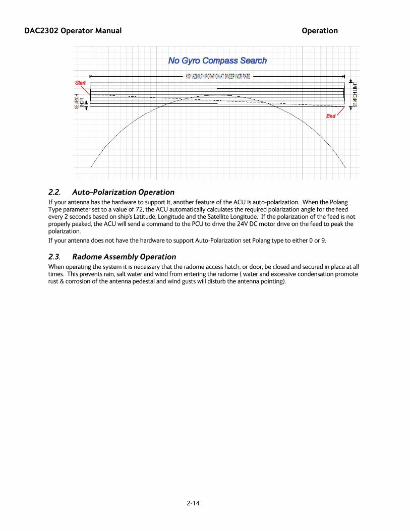
2.1.3. If the ship does not have a gyro compass to use as heading input to the Antenna Control Unit, you may manually key in the actual heading of the vessel and then re-target the desired satellite, every time you need to re-target a satellite, or configure the ACU to do a “No Gyro Search Pattern”.
No Gyro Search Pattern
You configure the ACU to use this pattern by using the following settings:
SEARCH INC - set to the default value for the frequency band that your antenna model is currently being used for (typically 15 counts).
SEARCH LIMIT – leave this set to the default value.
SEARCH DELAY – default, or any number of seconds from 1-255 that you would prefer that the ACU wait before starting an automatic search.
SWEEP INC – Larger antennas should have slower speeds and smaller antennas should have faster speeds:
Larger antennas should have slower speeds set to 0047 (= 5 degrees/second) for 2.4M to 3.6M antenna systems).
Mid size antennas can be driven a little faster, set to 0063 (= 8 degrees/second) for 2M antennas models).
Smaller antennas should have faster speeds, set to 0079 (= 18 degrees/second) for all 0.8M to 1.5M antenna models).
GYRO TYPE – MUST be set to zero for this search pattern.
SAT REF mode – MUST be ON for this search pattern.
Target any satellite longitude value which includes even tenths digit values (ie SAT 101.0 W or SAT 101.2 W). If the desired satellite longitude includes an odd tenths digit, you must round it up, or down, one tenth to make the tenths digit EVEN. The Antenna Control Unit calculates the Azimuth, Elevation and Polarization values it will use to target the antenna. However, without heading input, the ACU cannot target a “true azimuth” position (relative to true North). It will target the antenna to the calculated elevation and a repeatable “Start” relative azimuth position. In Series 04 antennas this relative position will be 90 degrees away from the nearest mechanical stop. In all other antennas it will be 000 degrees relative.
Initially the antenna will go to the “Start” relative azimuth position at the calculated elevation. Then the antenna will search up 450 degrees in azimuth, search up one Search Increment in elevation, search down 450 degrees in azimuth, search down two Search Increments in elevation, etc until Search Limit is reached. When the end of the search pattern is reached, the ACU will retarget the antenna back to the start point shown in the graphic below.
If the desired signal is found (AND network lock is achieved in the satellite modem) at this position, or anywhere within the search pattern, the ACU will terminate search and go into Tracking mode. If the desired signal is not found the ACU will wait SEARCH DELAY seconds and then begin the search pattern again. This cycle will repeat until the desired satellite signal is found or the operator intervenes.
DAC2302 Operator Manual Operation
2-14
2.2. Auto-Polarization Operation If your antenna has the hardware to support it, another feature of the ACU is auto-polarization. When the Polang Type parameter set to a value of 72, the ACU automatically calculates the required polarization angle for the feed every 2 seconds based on ship's Latitude, Longitude and the Satellite Longitude. If the polarization of the feed is not properly peaked, the ACU will send a command to the PCU to drive the 24V DC motor drive on the feed to peak the polarization.
If your antenna does not have the hardware to support Auto-Polarization set Polang type to either 0 or 9.
2.3. Radome Assembly Operation When operating the system it is necessary that the radome access hatch, or door, be closed and secured in place at all times. This prevents rain, salt water and wind from entering the radome ( water and excessive condensation promote rust & corrosion of the antenna pedestal and wind gusts will disturb the antenna pointing).

Setup – CommIF and HTML Pages DAC2302 Operator Manual
3-1
3. Setup – CommIF and HTML Pages
3.1. Configuring the COMM IF ports of the DAC-2202 ACU The Monitor and Control (M&C J3) port allows external control from a PC using a communications program such as Sea Tel’s ProgTerm or DacRemP via a straight 9 wire serial cable. This Port is used in conjunction with a diagnostic software connection to configure all communications settings, and/or for an Authorized Sea Tel Dealer to perform software uploads to the PCU, ACU Main PCB, and DVB Receiver.
The Ethernet Port allows use of a LAN connection to login into the ACU’s internal webpage’s to view or change system parameters using a web browser such as Internet Explorer or Mozilla Firefox. This 10BaseT Ethernet Port has a configurable static IP address with 2 TCP/IP connections for diagnostic software connections and a UPD Port for an Authorized Sea Tel Dealer to perform a software upload to the Comm IF Module.
The NMEA J2 Port allows 2 simultaneous NMEA-0183 connections on the same DB9 connector, defined as NMEA A and NMEA B. Both NMEA A (J2-Pin1 Rx+ and J2-Pin3 Tx-) and NMEA B (J2-Pin7 Rxe+ and J2-8 Txe-) Ports have selectable baud rates independent of each other. The following procedure describes the process of connecting the ACU to your Laptop and configuring all Comm IF Properties.
Hardware/Software Requirements:
• Laptop/Desktop with an available Serial Com Port and ProgTerm Version 1.33 (Build 11.Mar.2007 or later). If no DB9 Serial port is available use a USB to Serial Adapter or use IP version of ProgTerm. Standard Straight 9 wire serial cable (Sea Tel Part Number 120643-25 or equiv.)
• DAC2202 Antenna Control Unit
1. Turn Power off to ACU
2. Connect J3 M&C Port to Computer Com Port using a Male to Female RS232 Straight 9 wire serial cable
3. Turn Power on to ACU and then open Sea Tel’s ProgTerm M&C software program.
4. Configure ProgTerm’s Translation Mode. Click on “CommPort” then select “Dac 2200 to ACU (9600)”.
Insure that the bottom of screen reads “DAC 2K Translation ACU”
DAC2302 Operator Manual Setup – CommIF and HTML Pages
3-2
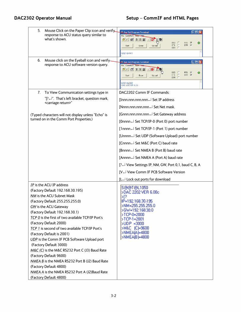
5. Mouse Click on the Paper Clip icon and verify response to ACU status query similar to what’s shown.
6. Mouse click on the Eyeball icon and verify
response to ACU software version query.
7. To View Communication settings type in
“[?↵”. That’s left bracket, question mark, <carriage return>”
(Typed characters will not display unless “Echo” is turned on in the Comm Port Properties.)
DAC2202 Comm IF Commands:
[Innn.nnn.nnn.nnn↵ Set IP address
[Nnnn.nnn.nnn.nnn↵ Set Net mask.
[Gnnn.nnn.nnn.nnn↵ Set Gateway address
[0nnnn↵ Set TCP/IP-0 (Port 0) port number
[1nnnn↵ Set TCP/IP-1 (Port 1) port number
[Unnnn↵ Set UDP (Software Upload) port number
[Cnnnn↵ Set M&C (Port C) baud rate
[Bnnnn↵ Set NMEA B (Port B) baud rate
[Annnn↵ Set NMEA A (Port A) baud rate
[?↵ View Settings IP, NM, GW, Port 0,1, baud C, B, A
[V↵ View Comm IF PCB Software Version
[L↵ Lock out ports for download
IP
(Factory Default 192.168.30.195)
is the ACU IP address
NM
(Factory Default 255.255.255.0)
is the ACU Subnet Mask
GW
(Factory Default 192.168.30.1)
is the ACU Gateway
TCP 0
(Factory Default 2000)
is the first of two available TCP/IP Port’s
TCP 1
(Factory Default is 2001)
is second of two available TCP/IP Port’s
UDP
(Factory Default 3000)
is the Comm IF PCB Software Upload port
M&C (C)
(Factory Default 9600)
is the M&C RS232 Port C (J3) Baud Rate
NMEA B
(Factory Default 4800)
is the NMEA RS232 Port B (J2) Baud Rate
NMEA A
(Factory Default 4800)
is the NMEA RS232 Port A (J2)Baud Rate

Setup – CommIF and HTML Pages DAC2302 Operator Manual
3-3
8. To change Communication Settings
Type “[Control Codennn<cr>”. That’s left bracket, control code alpha/numeric digit, parameter, <carriage return> (No Spaces).
Example: Change ACU IP address to 192.168.30.195 type: “[I192.168.30.195↵”
Example: Change J2 NMEA Port B Baud Rate to 9600
type: “[B9600↵”
9. To save parameters to Flash (Comm IF PCB)
Type “[W↵”. That’s Left Bracket, Capital “W”, <carriage return>(No Spaces). Verify “Done” is displayed after Saving Comm parameters.
**Do not turn power off to ACU until finished**
10. To reboot Comm IF software Type “[Z↵”.
That’s Left Bracket, Capital “Z”, <carriage return> (No Spaces). Verify “Comm IF Ver x.xx Port M&C (C)” is displayed.
3.2. Internal HTML Page The following procedure(s) define the process of connecting and logging into the DAC2202’s internal HTML page. **If the IP address for your DAC2202 has been changed from factory default or if is unknown use the “Configuring the COMM IF ports of the DAC-2202 ACU” procedure to view or change the existing parameters.
1. Connect the “ETHERNET” port on DAC-2202 to a Local Area Network (LAN) Connection or directly to an available Ethernet port on a Laptop/Desktop using a standard CAT5 cable.
2. Power on DAC2202
3. Configure the connected LAN connection with a static IP address which is on the same sub net as the DAC2202.
4. Start up your Internet Browser (i.e.
Internet Explorer, Mozilla Firefox, etc.) and type in the IP address of the DAC2202 into the address bar.
5. Log into the DAC2202 by typing in Username and Password information .
USERNAME: seatel
PASSWORD: 1234
DAC2302 Operator Manual Setup – CommIF and HTML Pages
3-4
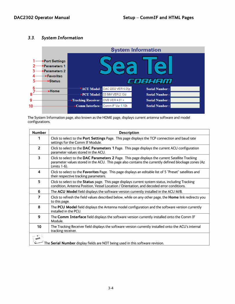
3.3. System Information
The System Information page, also known as the HOME page, displays current antenna software and model configurations.
Number Description
1 Click to select to the Port Settings Page. This page displays the TCP connection and baud rate settings for the Comm If Module.
2 Click to select to the DAC Parameters 1 Page. This page displays the current ACU configuration parameter values stored in the ACU.
3 Click to select to the DAC Parameters 2 Page. This page displays the current Satellite Tracking parameter values stored in the ACU. This page also contains the currently defined blockage zones (Az Limits 1-6).
4 Click to select to the Favorites Page. This page displays an editable list of 5 “Preset” satellites and their respective tracking parameters.
5 Click to select to the Status page. This page displays current system status, including Tracking condition, Antenna Position, Vessel Location / Orientation, and decoded error conditions.
6 The ACU Model field displays the software version currently installed in the ACU M/B.
7 Click to refresh the field values described below, while on any other page, the Home link redirects you to this page.
8 The PCU Model field displays the Antenna model configuration and the software version currently installed in the PCU.
9 The Comm Interface field displays the software version currently installed onto the Comm IF Module.
10 The Tracking Receiver field displays the software version currently installed onto the ACU’s internal tracking receiver.
The Serial Number display fields are NOT being used in this software revision.

Setup – CommIF and HTML Pages DAC2302 Operator Manual
3-5
3.4. Communication Port Settings
Number Description
1 The IP Address field displays the Static Internet Protocol address value currently stored in the Comm IF module (Flash). To change the IP address to match an existing LAN info structure, type in the desired value and click on the SUBMIT button. If the parameter change causes desirable operation click on the SAVE button to store value to memory. This address must conform to the nnn.nnn.nnn.nnn format where nnn is a number between 0 and 255.
2 The Net Mask field displays the Subnet Mask address value currently stored in the Comm IF module. To change the Subnet to match an existing LAN info structure, type in the desired value and click on the SUBMIT button. If the parameter change causes desirable operation click on the SAVE button to store value to Flash. This address must conform to the nnn.nnn.nnn.nnn format where nnn is a number between 0 and 255.
3 The Gateway field displays the Static Gateway Internet Protocol address value currently stored in the Comm IF module. To change the Gateway IP address to match an existing LAN info structure, type in the desired value and click on the SUBMIT button. If the parameter change causes desirable operation click on the SAVE button to store value to Flash. This address must conform to the nnn.nnn.nnn.nnn format where nnn is a number between 0 and 255.
4 The TCP Port 0 field displays the Transmission Control Protocol Port 0 value currently stored in the Comm IF Module. To change the Port value to match an existing LAN info structure, type in the desired value and click on the SUBMIT button. If the parameter change causes desirable operation click on the SAVE button to store value to Flash. This address must conform to the nnnn format where nnnn is a number between 0 and 65535.
5 The TCP Port 1 field displays the Transmission Control Protocol Port 1 value currently stored in the Comm IF Module. To change the Port value to match an existing LAN info structure, type in the desired value and click on the SUBMIT button. If the parameter change causes desirable operation click on the SAVE button to store value to Flash. This address must conform to the nnnn format where nnnn is a number between 0 and 65535.
6 The OpenAMIP Port field displays the Open Antenna-Modem Interface Protocol port value. This port is specifically used to communicate with an “Open AMIP” compatible satellite modem and should not be changed from the factory default.
7 The UDP Port displays the User Datagram Protocol Port value stored in the Comm IF Module. This port is specifically used to perform software upgrades to the Comm IF Module and should NOT be changed.
DAC2302 Operator Manual Setup – CommIF and HTML Pages
3-6
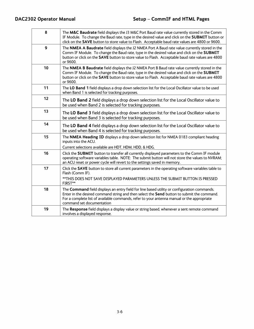
8 The M&C Baudrate field displays the J3 M&C Port Baud rate value currently stored in the Comm IF Module. To change the Baud rate, type in the desired value and click on the SUBMIT button or click on the SAVE button to store value to Flash. Acceptable baud rate values are 4800 or 9600.
9 The NMEA A Baudrate field displays the J2 NMEA Port A Baud rate value currently stored in the Comm IF Module. To change the Baud rate, type in the desired value and click on the SUBMIT button or click on the SAVE button to store value to Flash. Acceptable baud rate values are 4800 or 9600.
10 The NMEA B Baudrate field displays the J2 NMEA Port B Baud rate value currently stored in the Comm IF Module. To change the Baud rate, type in the desired value and click on the SUBMIT button or click on the SAVE button to store value to Flash. Acceptable baud rate values are 4800 or 9600.
11 The LO Band 1 field displays a drop down selection list for the Local Oscillator value to be used when Band 1 is selected for tracking purposes.
12 The LO Band 2 field displays a drop down selection list for the Local Oscillator value to be used when Band 2 is selected for tracking purposes.
13 The LO Band 3 field displays a drop down selection list for the Local Oscillator value to be used when Band 3 is selected for tracking purposes.
14 The LO Band 4 field displays a drop down selection list for the Local Oscillator value to be used when Band 4 is selected for tracking purposes.
15 The NMEA Heading ID displays a drop down selection list for NMEA 0183 compliant heading inputs into the ACU.
Current selections available are HDT, HDM, HDD, & HDG.
16 Click the SUBMIT button to transfer all currently displayed parameters to the Comm IF module operating software variables table. NOTE: The submit button will not store the values to NVRAM; an ACU reset or power cycle will revert to the settings saved in memory.
17 Click the SAVE button to store all current parameters in the operating software variables table to Flash (Comm IF).
**THIS DOES NOT SAVE DISPLAYED PARAMETERS UNLESS THE SUBMIT BUTTON IS PRESSED FIRST**
18 The Command field displays an entry field for line based utility or configuration commands. Enter in the desired command string and then select the Send button to submit the command. For a complete list of available commands, refer to your antenna manual or the appropriate command set documentation
19 The Response field displays a display value or string based, whenever a sent remote command involves a displayed response.
Setup – CommIF and HTML Pages DAC2302 Operator Manual
3-7
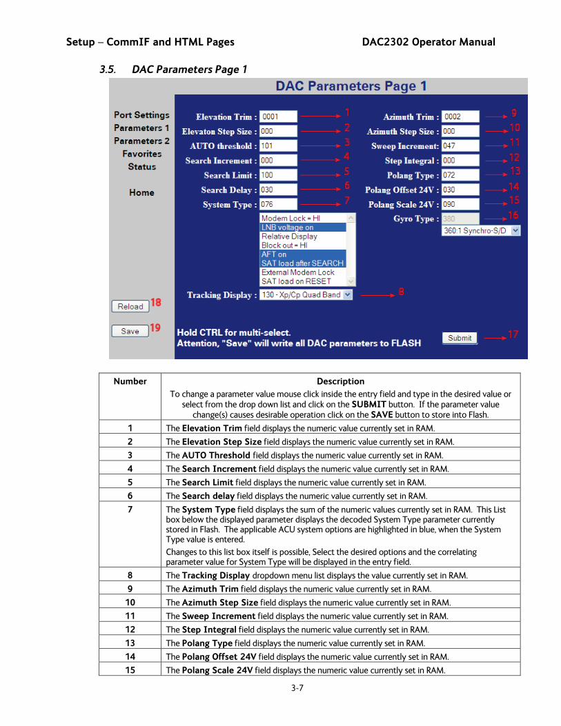
3.5. DAC Parameters Page 1
Number Description To change a parameter value mouse click inside the entry field and type in the desired value or
select from the drop down list and click on the SUBMIT button. If the parameter value change(s) causes desirable operation click on the SAVE button to store into Flash.
1 The Elevation Trim field displays the numeric value currently set in RAM.
2 The Elevation Step Size field displays the numeric value currently set in RAM.
3 The AUTO Threshold field displays the numeric value currently set in RAM.
4 The Search Increment field displays the numeric value currently set in RAM.
5 The Search Limit field displays the numeric value currently set in RAM.
6 The Search delay field displays the numeric value currently set in RAM.
7 The System Type field displays the sum of the numeric values currently set in RAM. This List box below the displayed parameter displays the decoded System Type parameter currently stored in Flash. The applicable ACU system options are highlighted in blue, when the System Type value is entered.
Changes to this list box itself is possible, Select the desired options and the correlating parameter value for System Type will be displayed in the entry field.
8 The Tracking Display dropdown menu list displays the value currently set in RAM.
9 The Azimuth Trim field displays the numeric value currently set in RAM.
10 The Azimuth Step Size field displays the numeric value currently set in RAM.
11 The Sweep Increment field displays the numeric value currently set in RAM.
12 The Step Integral field displays the numeric value currently set in RAM.
13 The Polang Type field displays the numeric value currently set in RAM.
14 The Polang Offset 24V field displays the numeric value currently set in RAM.
15 The Polang Scale 24V field displays the numeric value currently set in RAM.

DAC2302 Operator Manual Setup – CommIF and HTML Pages
3-8
16 The Gyro Type field displays the numeric value currently set in RAM. Select the desired Gyro Interface from the drop down menu selection list and the correlating parameter value for Gyro Type will be displayed in the entry field
17 Click the SUBMIT button to transfer all currently displayed parameters to the operating software variables table (working memory). NOTE: The submit button will not store the values to memory; an ACU reset or power cycle will revert to the old settings saved in NVRAM.
18 Click the “RELOAD” button to refresh the screen to the current ACU parameter values
19 Click the SAVE button to store all currently displayed parameters to Flash (68HC08).
3.6. DAC Parameters Page 2
Number Description
1 The SATELLITE field(s) present longitudinal position of the currently stored (or last targeted) satellite.
2 The Frequency MHZ field displays the numeric value currently stored in RAM.
3 The Baudrate field displays the numeric value currently stored in RAM.
4 The FEC field displays the selected value currently stored in RAM.
5 The Tone field displays the selected state currently stored in RAM.
6 The VOLT field displays the selected value currently stored in RAM.
7 The Target NID field displays the hexadecimal value currently stored in RAM.
8 The Band field displays the selected value currently stored in RAM.
9 The Tx Polarity field displays the selected value currently stored in RAM.
10 The Sat Skew field displays the numeric value currently stored in RAM.
11 The Az Limit 1 field displays the numeric value currently stored in RAM.
12 The Az Limit 2 field displays the numeric value currently stored in RAM.
13 The Az Limit 3 field displays the numeric value currently stored in RAM.
Setup – CommIF and HTML Pages DAC2302 Operator Manual
3-9
14 The Az Limit 4 field displays the numeric value currently stored in RAM.
15 The Az Limit 5 field displays the numeric value currently stored in RAM.
16 The Az Limit 6 field displays the numeric value currently stored in RAM.
17 The EL Limit 12 field displays the numeric value currently stored in RAM.
18 The EL Limit 34 field displays the numeric value currently stored in RAM.
19 The EL Limit 56 field displays the numeric value currently stored in RAM.
20 Click the SUBMIT button to transfer all currently displayed parameters to the operating software variables table (working memory). NOTE: The submit button will not store the values to memory, an ACU reset or Power cycle will revert to the old settings saved in NVRAM.
21 Click the RELOAD button to refresh the screen to display the current ACU parameter values
22 Click the SAVE button to store all currently displayed parameters to memory (NVRAM).
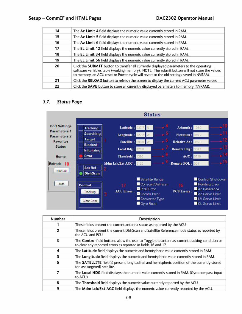
3.7. Status Page
Number Description
1 These fields present the current antenna status as reported by the ACU.
2 These fields present the current DishScan and Satellite Reference mode status as reported by the ACU and PCU.
3 The Control field buttons allow the user to Toggle the antennas’ current tracking condition or to clear any reported errors as reported in fields 16 and 17.
4 The Latitude field displays the numeric and hemispheric value currently stored in RAM.
5 The Longitude field displays the numeric and hemispheric value currently stored in RAM.
6 The SATELLITE field(s) present longitudinal and hemispheric position of the currently stored (or last targeted) satellite.
7 The Local HDG field displays the numeric value currently stored in RAM. (Gyro compass input to ACU)
8 The Threshold field displays the numeric value currently reported by the ACU.
9 The Mdm Lck/Ext AGC field displays the numeric value currently reported by the ACU.
DAC2302 Operator Manual Setup – CommIF and HTML Pages
3-10
10 The Azimuth field displays the Antenna’s True North Azimuth pointing angle.
11 The Elevation field displays the Antenna’s Elevation pointing angle referenced to the horizon.
12 The Relative AZ field displays the Antenna’s Azimuth pointing angle referenced to the vessels bow marker.
13 The Remote field displays the numeric value currently reported by the PCU. (Azimuth Stabilization Loop’s Heading Registry)
14 The AGC field displays the numeric value currently reported by the ACU.
15 The Remote POL field displays the numeric value currently reported by the PCU.
16 The PCU Errors box is a read only field that displays Pedestal reported errors currently triggered.
17 The ACU Errors box is a read only field that displays the decoded ACU reported errors currently triggered.
18 The Refresh field allows the user to adjust the page refresh settings, AUTO is selected by default, which refreshes the displayed page every 5 seconds
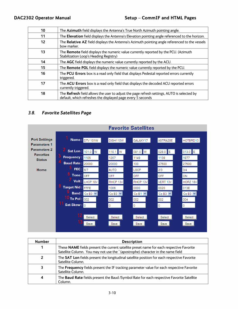
3.8. Favorite Satellites Page
Number Description
1 These NAME fields present the current satellite preset name for each respective Favorite Satellite Column. You may not use the ‘ (apostrophe) character in the name field
2 The SAT Lon fields present the longitudinal satellite position for each respective Favorite Satellite Column.
3 The Frequency fields present the IF tracking parameter value for each respective Favorite Satellite Column.
4 The Baud Rate fields present the Baud /Symbol Rate for each respective Favorite Satellite Column.
Setup – CommIF and HTML Pages DAC2302 Operator Manual
3-11
5 The FEC fields present the Forward Error Correction Rate for each respective Favorite Satellite Column.
6 The Tone fields present the 22Khz Tone State for each respective Favorite Satellite Column.
7 The Volt fields present the BDE voltage state for each respective Favorite Satellite Column.
8 The Target NID fields present the Hexadecimal Network Identification value for each respective Favorite Satellite Column.
9 The Band fields present a drop down listing of the available LNB Band selection for each respective Favorite Satellite Column.
10 The Tx Pol fields present the transmit for each respective Favorite Satellite Column.
11 The Sat Skew fields present the satellite Polarization Offset value for each respective Favorite Satellite Column.
12 Click on the Select button to submit the respective Favorite Satellite Column parameters into RAM
13 Click on the Save button to submit the respective Favorite Satellite Column parameters to Flash.

DAC2302 Operator Manual Setup – CommIF and HTML Pages
3-12
This Page Intentionally Left Blank