operator’s manual i - nj7p.org 11-5815-602-10-1 1-mar-87... · tm 11-5815-602-10-1 ......
TRANSCRIPT

ARMYNAVY
AIR FORCEMARINE CORPS
TM 11-5815-602-10-1EE 161-DT-OMl-010/E100-UGC-74B&C(V)3TO 31W4-2UGC74-11
TM 08008C–10/1
OPERATOR’S MANUAL
I EQUIPMENT
DESCRIPTION
Page 1–5
OPERATING
INSTRUCTIONSPage 2–0
DESCRIPTION
OF CONTROLSPage 2–1
PREVENTIVEMAINTENANCE
CHECKS ANDSERVICES (PMCS)
Page 2–30
IOPERATOR
MAINTENANCEPROCEDURES
Page 3-3
TROUBLESHOOTINGPage 3-0
SUBJECT INDEXPage Index–1
TERMINAL, COMMUNICATIONS AN/UGC-74B(V)3(NSN 5815-01-214-6237)
TERMINAL, COMMUNICATIONS AN/UGC-74C(V)3(NSN 5815-01-211-4122)
DEPARTMENTS OF THE ARMY, THE NAVY, THE AIR FORCE,AND HEADQUARTERS MARINE CORPS
1 MARCH 1987

This publication is required for official use or foradministrative or operational purposes only. Distribution is limited to US Government Agencies. Other requests for this document must be referred to Commander, US ArmyCommunications-Electronics Commander, and Fort Monmouth,Attn: AMSEL-ME-P, Fort Monmouth, NJ 07703-5000.

TM 11-5815-602-10-1
D O N O T T R Y T O P U L L O R G R A B T H E I N D I V I D U A L
I F P O S S I B L E , T U R N O F F T H E E L E C T R I C A L P O W E R
I F Y O U C A N N O T T U R N O F F T H E E L E C T R I C A L
P O W E R , P U L L , P U S H , O R L I F T T H E P E R S O N T O
S A F E T Y U S I N G A W O O D E N P O L E O R A R O P E O R
S O M E O T H E R I N S U L A T I N G M A T E R I A L
S E N D F O R H E L P A S S O O N A S P O S S I B L E
A F T E R T H E I N J U R E D P E R S O N I S F R E E O F
C O N T A C T W I T H T H E S O U R C E O F E L E C T R I C A L
S H O C K , M O V E T H E P E R S O N A S H O R T D I S T A N C E
A W A Y A N D I M M E D I A T E L Y S T A R T A R T I F I C I A L
R E S U S C I T A T I O N
A

TM 11-5815-602-10-1
WARNINGS
HIGH VOLTAGEIS USED IN THE OPERATION OF THIS EQUIPMENT
DEATH ON CONTACTMAY RESULT IF PERSONNELF AIL TO OBSERVE SAFEN PRECAUTIONS
—--------------------------------------------------- ---------------------- - -— —---- - -- —— --- - -— —---- -------------------------------------------------------------------------------------------Never work on electronic equipment unless there is another person nearby who is familiar with theoperation and hazards of the equipment and who is competent in administering first aid. Whentechnicians are aided by operators, they must be warned about dangerous areas.
Whenever possible, the power supply to the equipment must be shut off before beginning work on theequipment. Take particular care to ground every capacitor likely to hold a dangerous potential. When workinginside the equipment, after power has been turned off, always ground every part before touching it.
Be careful not to contact high voltage input connections of 115/230 volts ac when installing or operating thisequipment.
Whenever the nature of the operation permits, keep one hand away from the equipment to reduce the hazard ofcurrent flowing through vital organs of the body.
WARNING
Do not be misled by the term “low voltage”. Potentials as low as 50 volts may cause death under adverseconditions.
For Artificial Respiration, Refer to FM 21-1.
WARNING
Adequate ventilation should be provided while using TRICHLOROTRIFLUOROETHANE. Prolonged breathingof vapor should be avoided. The solvent should not be used near heat or open flame; the products ofdecomposition are toxic and irritating. Since TRICHLOROTRIFLUOROETHAN E dissolves natural oils, prolongedcontact with the skin should be avoided. When necessary use gloves which the solvent cannot penetrate. If thesolvent is taken internally, consult a physician immediately.
WARNING
Lithium organic batteries or cells are used in this equipment. They are potentially hazardous if misused ortampered with before, during, or after discharge. The following precautions must be strictly observed to preventpossible injury to personnel or equipment damage.
DO NOT heat, incinerate, crush, puncture, disassemble, or otherwise mutilate the batteries.
DO NOT short circuit, recharge, or bypass internal fuse.
DO NOT store equipment during long periods of nonuse in excess of 30 days.
TURN OFF the equipment immediately if you detect battery compartment becoming unduly hot, hear battery cells venting (hissing sound), or smell irritating sulphur dioxide gas. Remove and dispose of battery only after it is cool(30 -60 minutes).
B

TM 11-5815-602-10-1
HOW TO USE THIS MANUAL
This manual tells you how to operate and perform operator maintenance on theCommunications Terminal AN/UGC-74B & C(V)3. Information not identified to aparticular model applies to the Model B. Information that applies only to the Model C isidentified as Model C information, and the MODEL C ONLY headings are capitalized andunderlined as shown.
Location of Subjects in Manual
In this manual, paragraphs and pages are numbered in succession by chapter. Forexample: Paragraph 2-14 is paragraph 14 in chapter 2. Page 3-5 is page 5 in chapter 3.
If you are looking for specific information, use subject INDEX the back of thismanual to locate page number where topic is described.
For rapid location of a required subject, contents of chapter are listed alphabeticallyon the first page of each chapter.
Refer to Appendix A, REFERENCES, for the complete title of all forms, technicalmanuals and military specifications referenced in this manual.
Refer to LIST OF ABBREVIATIONS and GLOSSARY in Chapter 1 for a definition ofthe abbreviations and unusual terms used in this manual.
Use of manual for Task Performance
You must become thoroughly familiar with all the operating controls, switches, lamps,and keys before you can properly use and maintain the terminal. Chapter 2 describes theuse of operator controls, while Chapter 3 tells you how to maintain the equipment.
As a further aid to knowing operation procedures, appendices E through J, located inthe back of this manual, provide information and detailed examples of operator andterminal responses in the operational states.
Use this manual in conjunction with station’s Standard Operating Procedures (SOP)when formatting messages. Appendix H provides an example of a JANAP 128(H)PLAINDRESS header and message.
You must familiarize yourself with all the maintenance procedures before beginningthe maintenance task.
Do not perform maintenance tasks that are assigned to a maintenance level higherthan you are authorized to perform. Call your supervisor or next higher level ofmaintenance if you have a problem not described in this manual.
i

Technical ManualNo. 11-5815-602-10-1Technical ManualEE 161-DT-OMl-010/E110-UGC-74B&C(V)3Technical OrderNo. 31W4-2UGC74-11Technical Manual08008C-10/1
TM 11-5815-602-10-1 TM EE 161-DT-OMl-010/E110-UGC-74B&C(V)3
T0 31W4-2UGC74-11 TM 08008C-10/1
DEPARTMENTS OF THE ARMY,THE NAVY, AND THE AIR FORCE,HEADQUARTERS MARINE CORPSWashington, DC, 1 March 1987
OPERATOR’S MANUAL TERMINAL, COMMUNICATIONS AN/UGC-74B(V)3
(NSN 5815-01-214-6237) TERMINAL, COMMUNICATIONS AN/UGC-74C(V)3
(NSN 5815-01-211-4122)
REPORTING OF ERRORS AND RECOMMENDING IMPROVEMENTS
You can help improve this manual. If you find any mistakes or if youknow of a way to improve the procedures, please let us know. Mail yourletter, DA Form 2028 (Recommended Changes to Publications and BlankForms), or DA Form 2028-2 located in back of this manual direct to:Commander, US Army Communications-Electronics Command and FortMonmouth, ATTN: AMSEL-ME-MP, Fort Monmouth, New Jersey 07703-5000.
For Air Force, submit AFTO Form 22 (Technical Order System Publi–cation Improvement Report and Reply) in accordance with paragraph 6-5,Section Vl, T.O. 00-5-1. Forward direct to prime ALC/MST activity.
For Navy, mail comments to the Commander, Space and Naval WarfareSystems Command, ATTN: SPAWAR 8122, Washington, DC 20363-5100.
For Marine Corps Units, submit NAVMC 10772 to Commanding General,Marine Corps Logistics Base (Code 850), Albany, GA 31704-5000.
In either case, a reply will be furnished direct to you.
TABLE OF CONTENTS
HOW TO USE THIS MANUAL . . . . . . . . . . . . . . . . . . . . . . . . . . . . . . . . . . . . . . . . . . . . . . . . . . . . . . . . . . . . . . . . . . .
PAGE
i
CHAPTER 1 INTRODUCTION. . . . . . . . . . . . . . . . . . . . . . . . . . . . . . . . . . . . . . . . . . . . . . . . . . . . . . . . . . . . . . . . . . . . . . . . . . . . . . . . . . . . . . . . . . . . . . . 1-0
Section I Genera l... . . . . . . . . . . . . . . . . . . . . . . . . . . . . . . . . . . . . . . . . . . . . . . . . . . . . . . . . . . . . . . . . . . . . . . . . . 1-1II Equipment Description . . . . . . . . . . . . . . . . . . ... . . . . . . . . . . . . . . . . . . . . . . . . . . . . . . . . . . . . . ... . . . . . . . . . . .. 1-5
CHAPTER 2 OPERATING INSTRUCTIONS . . . . . . . . . . . . . . . . . . . . . . . . . . . . . . . . . . . . . . .. 2-0
Section I Description and Use of Operator’s Controls and Indicators . . . . . . . . . . . . . . . . . . . . . 2-1II Preventive Maintenance Checks and Services . . . . . . . . . . . . . . . . . . . . . . . . . ... . . . . . . . . . . . . . .2-30Ill Operation Under Usual Conditions . . . . . . . . . . . . . . . . . . . . . . ... . . . . . . . . . . . . . . . . . . . . . . . . . . . . . . . ..2-35IV Operation Under Unusual Conditions . . . . . . . . . . . . . ... . . . . . . . . . . . . . .. 2 - 8 7

TM 11-5815-602-10-1
TABLE OF CONTENTS - Continued
CHAPTER 3
Section III
A P P E N D I X A
B
C
D
E
F
G
H
I
J
OPERATOR MAINTENANCE INSTRUCTIONS . . . . . . . . . . . . . . . . . . . . . . . . . . . . . . . . . .
Troubleshooting Procedures . . . . . . . . . . . . . . . . . . . . ... . . . . . . . . . . . . . . . . . . . . . . . . . . . . . . . . . . . . . .Operator Maintenance Procedures . . . . . . . . . . . . . . . . . . . . . . . . . . . . . . . . . . . . . . . . . . . . . . . . . . . . . . . .
REFERENCES . . . . . . . . . . . . . . . . . . . . . . . . . . . . . . . . . . . . . . . . . . . . . . . ..
COMPONENTS OF END ITEM LIST . . . . . . . . . . . . . . . . . . . . . . . . . . . . .
ADDITIONAL AUTHORIZATION LIST . . . . . . . . . . . . . . . . . . . . . . . . . . . . . .
EXPENDABLE SUPPLIES AND MATERIALS LIST . . . . . . . . . . . . . ..
AMERICAN NATIONAL STANDARD CODE FOR INFORMATIONINTERCHANGE (ASCII) AND KEYBOARD TABLES . . . . . . . . . . . . . . . . .
OPERATOR EXAMPLES - SYSTEM COMMANDS . . . . . . . . . . . . . . . . . . . . ..
OPERATOR EXAMPLES - PARAMETER SUBCOMMANDS . . . . . . . . . ... . ..
OPERATOR EXAMPLES - EDIT SUBCOMMANDS . . . . . . . . ... . . . . . . . . . ..
SUMMARY LISTS OF OPERATOR ACTIONS AND TERMINALRESPONSES . . . . . . . . . . . . . . . . . . . . . . . . . . . . . . . . . . . . . ..
HELP COMMAND MESSAGES . . . . . . . . . . . . . . . . . . . . . . . . . . . . . . . . . . . . . . .
PAGE
3-0
3-13-3
A-1
B-1
C-1
D-1
E-1
F-1
G-1
H-1
l-1
J-1Table J-1. SYSTEM COMMANDS . . . . . . . . ... . . . . . . . . . . . . . . . . .. . . . . J-1Table J-2. PARAMETER SUBCOMMANDS . . . . . . . . . ... . . . . . . . . . . . . . . J-3Table J-3. EDIT SUBCOMMANDS . . . . . . . . ... . . . . . . . . . . . . . . . . . . . . . J-5
INDEX......... . ..... . . . . . . . . . . . . . . . . . . . . . . . . . . . . . . . . . . . . . . . . . . . . . . . . . ..I N D E X - 1
NOTE
Refer to the latest issue of DA Pam 310-1 to determine whether there are neweditions, changes or additianal publications pertaining to theequipment. Marine Corps personnel refer to the latest issue of SL-1-2 to determinewhether there are any new editions.
iii

TM 11-5815-602-10-1
CHAPTER 1
INTRODUCTION
Characteristics, Capabilities, and Features of the Terminal . . . . . . . . . . . . . . . . . . . . . . . . . . . . . . . . . . . . . . . . . .Destruction of Materiel to Prevent Enemy Use . . . . . . . . . . . . . . . . . . . . . . . . . . . . . . . . . . . . . . . . . . . . . . . . . . . . . . . . . . . . . . . . . . . . .Differences Between Models B and C . . . . . . . . . . . . . . . . . . . . . . . . . . . . . . . . . . . . . . . . . . . ......,...............................,Equipment Data . . . . . . . . . . . . . . . . . ..Glossary. . . .. . . . . . . . . . . . . . . ... . . ..Hand Receipt (HR) Manual ..,,... . . . . . . . . . . . . . . . . . . . . . . . . . . . . . . . . . . . . . . . . . . . . . . . . . . . . . . . . . . ...,.,,, . . . .List of Abbreviations . . . . . . . . . . . . . . . . . . . . . . . . . . . . . . . . . . . . . . . . . . . . . . . . . . . . . . . . . . . . . . . . . . . . . . . . . . . . . . . . . . . . . . . . . . . . . . . . . . . . . . . . .Maintenance Forms, Records, and Reports . . . . . . . . . . . . . . . . . . . . . . . . . . . . . . . . . . . . . . . . ..Nomenclature Cross Reference List . . . . . . . . . . . . . . . . . . . . . . . . . . . . . . . . . . . . . . . . . . . . . . .Reporting Equipment Improvement Recommendations (EIR) . . . . . . . . . . . . . . . . . . . . . . . . Scope . . . . . . . . . . . . . . . . . . . . . . . . . . . . . . . . . . . . . . .. . .
PAGE
1-51-11-71-81-31-11-21-11-21-11-1
MODEL C ONLY
Figure 1-1. TERMINAL, COMMUNICATIONS AN/UGC-74B OR C(V)3 WITH COPYHOLDER ~ -
1-0

TM 11-5815-602-10-1
Section I. GENERAL
1-1. SCOPE
This manual is a guide for the installation and operation of Terminal, CommunicationsAN/UGC–74B(V)3 and AN/UGC-74C(V)3 (fig. 1-1).
1-2. MAINTENANCE FORMS, RECORDS, AND REPORTS
a. Reports of Maintenance and Unsatisfactory Equipment. Department of the Army forms andprocedures used for equipment maintenance will be those prescribed by DA PAM 738-750, TheArmy Maintenance Management System (TAMMS), Air Force personnel will use AFR 66-1 formaintenance reporting and TO-00-35D54 for unsatisfactory equipment reporting. Navy personnelwill report maintenance performed utilizing the Maintenance Data Collection Subsystem (MDCS)IAW OPNAVINST 4790.2, Vol 3 and unsatisfactory material/conditions (UR submissions) IAWOPNAVINST 4790.2, Vol 2, chapter 17. Marine Corps personnel will use TM-4700-15/1 EquipmentRecord Procedures.
b. Packaging Improvement Report. Fill out and forward SF 364 (Packaging ImprovementReport) as prescribed in AR 735-11-2/DLAR 4140.55/NAVSUPINST 4355.73B/AFR 400-54/MCO 4430.3H.
c. Discrepancy in Shipment Report (DISREP) (SF 361). Fill out and forward Discrepancy inShipment Report (DISREP) (SF 361) as prescribed in AR 55-38 /NAVSUPINST 4610.33C/AFR75-18/MCO P4610.19D/DLAR 4500.15.
1-3. HAND RECEIPT (-HR) MANUAL
This manual has a companion document with a TM number followed by "-HR" (Hand Receipt).TM 11-5815-602-10-1-HR consists of preprinted hand receipts (DA Form 2062) that list end itemrelated equipment (i.e., COEI, Bll, and AAL) you must account for. As an aid to propertyaccountability, additional -HR manuals may be requisitioned from The US Army Adjutant GeneralPublications Center, Baltimore, MD, in accordance with the procedures in Chapter 3, AR 310-2,and DA PAM 310-10-2.
1-4. REPORTING EQUIPMENT IMPROVEMENT RECOMMENDATIONS (EIR)
a. Army. If your Terminal, Communications AN/UGC-74B or C(V)3 needs improvements, let usknow. Send us an EIR. You, the user, are the only one who can tell us what you don’t likeabout your equipment. Let us know why you don’t like the design. Put it on an MCO 4855.10(Quality Deficiency Report). Mail it to Commander, US Army Communication-Electronics Commandand Fort Monmouth, ATTN: AMSEL-PA-MA-D, Fort Monmouth, New Jersey 07703-5000. We’ll send you a reply.
b. Air Force. Air Force personnel are encouraged to submit EIRs in accordance withAFR 900-4.
c. Navy. Navy personnel are encouraged to submit EIRs through their local BeneficialSuggestion Program.
d. Marine Corps. QDR shall be reported on SF 368 in accordance with MCO P4855.10 Quality Deficiency ReportManual. Submit to Commanding General, Marine Corps Logistics Base (Code 856) Albany, Georgia.
1-5. DESTRUCTION OF MATERIEL TO PREVENT ENEMY USE
Refer to TM 750-244-2 for procedures covering destruction of Army or Marine Corps materielto prevent enemy use.

TM 11-5815-602-10-1
1-6. NOMENCLATURE CROSS-REFERENCE LIST
Common names will be used when the major componentsmanual.
Common Name Nomenclature
TerminalPrinter AssemblyUniversal CPU Circuit CardCommunications Circuit CardPrint Control Circuit CardChassisFilterInterfacePower SupplyKeyboardBattery Backup CablePower CablePower CablePower CableHi-Level CableLow-Level CableLow-Level Clock Cable
MODEL C ADDITIONAL COMPONENTS
of the terminal are mentioned in this
Terminal, Communications AN/UGC-74B and C(V)3Teleprinter Assembly (K3A1)Circuit Card Assembly, Universal CPU (3A1A1)Circuit Card Assembly, Communications (3A1A3)Circuit Card Assembly, Printer Control (3A1A4)Chassis Assembly (3A1A6)Filter Assembly (3A1A6FL1)Interface Assembly (3A1A7)Circuit Card Assembly, Power Supply (3A1PS1)Assembly, KeyboardAssembly, Cable,Assembly, Cable,Assembly, Cable,Assembly, Cable,Assembly, Cable,Assembly, Cable,Assembly, Cable,
SM-D-915897
Battery Backup SM-D-915890Power, dc, SM-D-764480Power, 115 V ac, SM-D-764481Power, 230 V ac, SM-D-764482Hi-Level, XMIT/RCV, SM-D-915889Low-Level, XMIT/RCV, SM-D-915896Low-Level, Clock, XMIT/RCV,
Aux Interface Card Circuit Card Assembly,Auxiliary Memory Module (AMM) Memory Unit, AuxiliaryAM/RC Card Circuit Card Assembly,
Auxiliary Interface (3A1A2)MU-856 /UGC-74 (3A3)Auxiliary Memory/
Relay Control ler (AM/RC) (3A2A3)
NOTEOfficial nomenclature must be used when filling out report forms or whenreferring to technical manuals.
1-7. LIST OF ABBREVIATIONS
Abbreviations are spelled out the first time they appear in this manual. A complete list ofabbreviations used in this manual is given below.
AMM . . . . . . . . . . . . . . . . . . . . . . . . .AM/RC . . . . . . . . . . . . . . . . . . . . . .AM/RF . . . . . . . . . . . . . . . . . . . . . . .ASCII . . . . . . . . . . . . . . . . . . . . . . . . .BAT . . . . . . . . . . . . . . . . . . . . . . . . . . .BEL . . . . . . . . . . . . . . . . . . . . . . . . . . .BRT . . . . . . . . . . . . . . . . . . . . . . . . . . .BS . . . . . . . . . . . . . . . . . . . . . . . . . . . .CPU . . . . . . . . . . . . . . . . . . . . . . . . . . .CR . . . . . . . . . . . . . . . . . . . . . . . . . . . .CTL . . . . . . . . . . . . . . . . . . . . . . . . . . .
Auxiliary Memory ModuleAuxiliary Memory/Relay ControllerAuxiliary Memory/Relay FunctionAmerican Standard Code for Information InterchangeBatteryBell CodeBrightBackspaceCentral Processing UnitCarriage ReturnControl
1 -2

TM 11-5815-602-10-1
DEL ............................DLC ............................DLL ............................EMI ..............................ETM ...........................HLT .............................ICT .............................INT/EXT ...................K S R .............................L F ..................................LOC ...........................MAX ..........................M S G RCVD ..............MWO .............................NRZ ............................R E C ...............................REV ............................RFI .............................R O .............................S O P ..........................XMIT ..............................
1-8. GLOSSARY
DeleteDelete Last CharacterDelete Last LineElectro Magnetic InductionElapsed Time MetersHaltIntelligent Communications TerminalInternal/ExternalKeyboard Send/ReceiveLine-FeedLockM a x i m u mMessage ReceivedModification Work OrdersNon-Return to ZeroRecordReviewRadio Frequency InterferenceReceive OnlyStandard Operating ProcedureTransmit
Buffer . . . . . . . . . . .
Default Normally set conditions or parameters that areautomatically preset at equipment power up.
Delimiter . . . . . . . . . . . . . . . . . . . . . . . . .
Access . . . . . . . . . . . . . . . . . . . . . . . . . The reading of a stored set of data but allowing the datato remain stored unchanged.
ASCII . . . . . . . . . . . . . . . . . . . . . . . . . An abbreviation for American Standard Code forInformation Interchange. A seven-bit plus parity codedeveloped by the American Standards Association. (Referto Appendix E for complete description of ASCII.)
Baud Code FIG-LTRS . . . . . . . . . . . . . . . . . . . . A 5-level code used for telegraph keyboard printers,punches and readers. Five bits can accept only 32 specialcodes, of which two are figures (FIGS) and letters(LTRS). Placing the FIGS or LTRS code before other bitcombinations permits dual definition of the remainingcodes. So when a Baudot terminal is interfaced to acomputer, the software must maintain proper FIGS-LTRSstatus in order to interpret the necessary data properly.
Baud Rate ....................... In data communications, a fixed amount of time isdevoted to sending a pulse, known as a binary digit or“bit”. A bit can be either a positive pulse, as a telegraphdot, or a blank, as a telegraph pause. The number of bitsthat can be transmitted in 1 second is the baud rate.
A storage device used to compensate for difference inthe rate of flow of information or the time ofoccurrence of events.
Any ASCII character used as a space or separator. Itcannot appear in the same string for which it is adelimiter.

TM 11-5815-602-10-1
GLOSSARY - Continued
Envelope . . . . . . . . . . . . . . . . . . . . . . . . .
Field
Font
Interface
. . . . . . . . . . . . . . . . . . . . . . . . .
. . . . . . . . . . . . . . . . . . . . . . . . .
. . . . . . . . . . . . . . . . . . . . . . . . .
Justify . . . . . . . . . . . . . . . . . . . . . . . . .
Line Pointer . . . . . . . . . . . . . . . . . . . . . . . .
Mnemonic (Ni-mon’-ik) . . . . . . . ..
Non-Return Zero (NRZ) . . . . . . . ..
A group of binary digits including data and call con-trol signals, which is transmitted or received as acomplete unit. The data, all control signals, andpossibly error control information, are arranged in aspecific format.
A single character or group of characters treated asone uni t or part of a system command or subcommand.
One set of printable characters of the same style, sizeand orientation.
A method used to interconnect two equipments orsystems. The method includes the type, quality andfunction of the interconnecting circuits and the typeand form of signals to be interchanged through thesecircuits.
To space a typewritten line so that it is exactly theintended length.
Position within the message file which always points tothe first character of the current line.
To remember, helping, or meant to help the memory.
A mode of recording in which each state of the
Port
Prompt
Renvelope
Tenvelope
medium corresponds to one binary state. In this mode,the state of the recording medium changes when theinformation changes from 1 to 0 or from 0 to 1.
NOTE"NRZ modified” is also often called “NRZ”.
Parity Bit . . . . . . . . . . . . . . . . . . . . . . . . . A binary digit attached to an array of bits to make thesum of all the bits either always odd or always even.
Parity Check . . . . . . . . . . . . . . . . . . . . . . . . . Addition of non-information bits to data, making thenumber of ones in a grouping of bits either always evenor always odd. This permits detection of bit groupingswhich contain single errors. It may be applied tocharacters, blocks, or any convenient bit grouping.
. . . . . . . . . . . . . . . . . . . . . . . . . An input/output connection used for exchange ofinformation with other equipments.
. . . . . . . . . . . . . . . . . . . . . . . . . A message from the equipment giving information to orrequesting information from the operator.
. . . . . . . . . . . . . . . . . . . . . . . . . Allows the operator to set the envelope which is putaround a message for reception by the system. Thissequence never appears in the message storage and isused for communications purposes only.
. . . . . . . . . . . . . . . . . . . . . . . . . Allows the operator to set the envelope which is putaround a message for transmission by the system. Thissequence never appears in the message storage and isused for communications purposes only.
1-4

TM 11-5815-602-10-1
Section Il. EQUIPMENT DESCRIPTION
1-9. CHARACTERISTICS, CAPABILITIES AND FEATURES OF THE TERMINAL
CHARACTERISTICS
Ž Composes, edits, transmits, receives, prints, and stores messages.Ž Operates in half- or full-duplex communication modes.Ž Utilizes both ASCII and Baudot character codes.Ž Uses signaling speeds of 45.5, 50, 75, 150, 300, 600, and 1200 bauds using an
internal clock.Ž Other rates are available provided an external clock is used.Ž Operates as an intelligent communications terminal, a keyboard send/receive
terminal, or a receive-only terminal.Ž Provides message header types JANAP-128, ACP-127 U.S. Supplement 1, and
ACP-127 NATO Supplement 3.
MODEL C ADDITIONAL CHARACTERISTICS
Ž Relays messages to other Model C terminals in a local area network [LAN).Ž Stores messages during power down.
CAPABILITIES AND FEATURES
Housed in a ruggedized combination case, Some of the uses in tactical field equipmentare as follows:
Ž Moving vehicles.Ž Aircraft.Ž Field shelters.• Secure (crypto) locations where protection against electromagnetic interference is
required.
1-5

TM 11-5815-602-10-1
LOCATION OF MAJOR COMPONENTS
Figure 1-2, MAJOR COMPONENTS OF TERMINAL
1-6

TM 11-5815-602-10-1
1-10. DIFFERENCES BETWEEN MODELS B AND C
CHARACTERISTICS
Ž When not in battery backup, Models B and C lose messages from message memorywhen powered down or during self-test. Model C maintains message storageintegrity in the Auxiliary Memory Module during the same conditions.
CAPABILITIES AND FEATURES
• Model B can transmit messages to one other terminal at a time. Model C canadditionally relay messages to up to 15 other AMM-equipped terminals.
• Models B and C store 35 pages of messages before becoming full. Model Cmaintains message memory availability through an automatic save and printprocess.
1. AUTOSAVE message to AMM.2. AUTOPRINT message after saved.3. Delete message from message memory after completing printout.
• Model C AMM may be removed, transported to a different Model C terminalanywhere and installed and fully utilized. The message(s) stored in the AMM isintact and accessible.
Ž Model B can store 56,000 characters in the message memory. Model C can storean additional 120,000 characters in the AMM.
EQUIPMENT HARDWARE
Ž Model C has a relay port connector mounted on the keyboard assembly
Ž Model C keyboard assembly contains an Auxiliary Memory/Relay Controller(AM/RC) circuit card assembly (3 A2A3).
• Model C Auxiliary Memory Module mounts on the right-hand side of the keyboardassembly (fig. 1-2).
• Model C has a fourth circuit card assembly (3 A1A2) mounted in the chassis.
1-7

TM 11-5815-602-10-1
1-11. EQUIPMENT DATA
The technical characteristics and equipment data are as follows:
Operating Speeds
Baud Rate [ ASCII Code
75 10 unit (1 stop bit)11 unit (2 stop bits)
150 10 unit (1 stop bit)11 unit (2 stop bits)
300 10 unit (1 stop bit)11 unit (2 stop bits)
600 10 unit (1 stop bit)11 unit (2 stop bits)
1200 10 unit (1 stop bit)11 unit (2 stop bits)
Baud Rate I Baudot Code
45.5 7 unit (1 stop bit)8 unit (2 stop bits)
50 7 unit (1 stop bit)8 unit (2 stop bits)
75 7 unit (1 stop bit)8 unit (2 stop bits)
150 7 unit (1 stop bit)8 unit (2 stop bits)
300 7 unit (1 stop bit)8 unit (2 stop bits)
600 7 unit (1 stop bit)8 unit (2 stop bits)
1200 7 unit (1 stop bit)8 unit (2 stop bits)
System Application
a. Full-Duplex,Ž Send and receive at the same time.
b, Half-Duplex,Ž Receive-only. Uses only the terminal’s receive capabilities.• When operating in this state, the terminal does not use the keyboard, Message
reception and printing are performed automatically,
System Interface
a. Operates with the following COMSEC devices:Ž VINSON (TSEC/KY-57)• KG-30 (TSEC/KY-30)� DLED (TSEC/KG-84)Ž KW-7 (TSEC/KW-7)
b. Also operates with the following equipment:Ž TH-22/TG� MD-522/GRC
1-8

TM 11-5815-602-10-1
KeyboardŽ Standord key board arrangetnent plus four editing keys
Printera. Type and Print Rate:
Ž Dot Matrix (6 x 9 dot pattern)• 120 characters per second throughput rate
b . P r• Operator selectable from 40 to 132 characters inclusiveŽ Line length is set at 80 characters in the POWER ON condition
Paper Type and Capacity
• Fanfold paper capability is optional
Other Printer Features• Single or double line-feed• Paper-low lamp� Automatic shutdown of printing when paper runs out and condition indicator
transmitted to sending terminal
Power RequirementŽ Model B: 100 watts, maximum – steady stateŽ Model C: 135 watts, maximum – steady stateŽ Model B and Model C: battery backup – 2 amps maximum
Operating Voltages• 26 (±4) volts dcŽ 115 volts ac (±15%), 50, 60, or 400 Hz (±5%)• 230 volts ac (±15%), 50, 60, or 400 Hz (±5%)
Environmental Conditionsa. Operating Temperature:
�� Model B: -25°F to +155°F (-32°C to +68°C)• Model C: +32°F to +131°F (0°C to +55°C) with AMM attached
b. Non-Operating Temperature:Ž Model B: -65°F to +155°F (-54°C to +68ºC)• Model C: -40°F to +131°F (-40°C to +55°C)
c. Case Closed:• Water and dust proof
M O D E L
Ž AMM in shipping cover is water and dust proof
d. Case Cover Removed:Ž Spray proof
1-9

TM 11-5815-602-10-1
Physical Characteristicsa. Total Weight:
Ž Model B: 103 lbs. equipment with cover and copyholder• Model C: 107 Ibs. equipment, cover, copyholder, and AMM
b. Dimensions:• 21.75 inches longŽ 17.5 inches wide• 9.5 inches high
MODEL C ONLY
Ž AMMWeight: 4 Ibs. with shipping coverWidth: 5.2 inchesHeight: 4.1 inchesDepth: 1.7 inches
1-10

TM 11-5815-602-10-1
Figure 1-4. SIDE VIEW OF TERMINAL, FULLY EXTENDED
Figure 1-5. REAR VIEW OF TERMINAL
1-11

TM 11-5815-602-10-1
CHAPTER 2
OPERATING INSTRUCTIONS
PAGE
Basic Command Errors . . . . . . . . . . . . . . . . . . . . . . . . . . . . . . . . . . . . . . . . . . . . . . . . ..2 - 5 4Dustcover Controls and Indicators . . . . . . . . . . . . . . . . . . . . . . . . . . . . . . . . . . . . .. . . . . . . . . . . . . . . . . . . . . . ..2 - 1Error Message List . . . . . . . . . . . . . . . . . . . . . . . . . . . . . . . . . . . . . 2-48ICT State Operating Instructions . . . . . . . . . . . . . . . . . . . . . . . . . . . . . . . 2-43Inputting Commands . . . . . . . . . . . . . . . . . . . . . . . . . . . . . . . . . . . . . 2-54Internal Controls and Switches . . . . . . . . . . . . . . . . . . . . 2 -6Keyboard Keys 2-14. . . . . . . . . . . . . . . . . . . . . . . . . . . . . . . . . . . . . . . . . . . . . . . . . . . . . . . . . . . . . .Message Memory 2-57. . . . . . . . . . . . . . . . . . . . . . . . . . . . . . . . . . . . . . . . . . . . . . . . . . . . . . . . . . . . . . . . .Operating States and Nonoperational Conditions . . . . . . . . . . . . . . . ..2 - 1 8Operating Procedures 2-38. . . . . . . . . . . . . . . . . . . . . . . . . . . . . . . . .. . . . . . . . . . . . . . . . . . . . . . . . . . . . . . . . . .
Receive Only (RO) . . . . . . . . . . . . . . . . . . . . . . . . . . . . . . . . . . . . . . . . . .. . . . . . . . . . . . . . . . . . .2-41Keyboard Send or Receive . . . . . . . . . . . . . . . . . . . . . . . .. . . . . . . . . . . . . . . . . . . . . . . . 2-42Intelligent Communications Terminal . . . . . . . . . . . . . . . . . . . . . . . . . . . . . . ..2 - 4 3
Operational Tests with Distant Station 2-84. . . . . . . . . . . . . . . . . . . . . . . . . . . . . . . . . . . . . . . . . . .Operation Under Emergency Conditions . . . . . . . . . . . . . . . . . . . . . . . . . . . . . . . . . . . ..2 - 8 9Operation Under Unusual Conditions . . . . . . . . . . . . . . . . . . . . . . . . . . . . . . . . . . . . . ..2 - 8 7Preemption of Operator 2-60. . . . . . . . . . . . . . . . . . . . . . . . . . . . . . . . . . . . . . . . . . . . . . . . . . . . . . . . . . . . . .Preliminary Starting Procedures . . . . . . . . . . . . . . . . . . . . . . . . . . . . . . . . . . . 2-35Preparation for Movement . . . . . . . . . . . . . . . . . . . . . . . . . . . . . . . . . . . . . . . . . . . . . . . ...2-90Prompt Sequence Indicators . . . . . . . . . . . . . . . . . . . . . . . . . . . . . . . . . . . . . . . . . . . . . 2-55Preventative Maintenance Checks and Services . . . . . . . . . . . . . . . . . . . . . . . . .. . ... . . . . . . . . . . . 2-31Receive Message Process . . . . . . . . . . . . . . . . . . . . . . . . . . . . . . . . . . . . . . . . . . . . . . . . . . . . . . . . ...2 - 5 7Self-Test Condition . . . . . . . . . . . . . . . . . . . . . . . . . . ... . . . . . . . . . . . . . . . . . . ... . . . . . . . . .. 2-22Systems Abbreviations Table . . . . . . . . . . . . . . . . . . . . . . . . . . . . . . . . . 2-47Systems Commands . . . . . . . . . . . . . . . . . . . . . . . . . . . . . . . . . . . . . . . . . . . . . .. . . . . . . . . . . . . . . . . . . . . . . ..2 - 6 1
Parameter . . . . . . . . . . . . . . . . . . . . . . . . . . . . . . . . . . ... . . . . . . . . . . . . . . . . . . . . . . . . . . . . . . . . . . . . . ... . . . . . . . . . . . . . . . . . . . . . . . . . . . ..2 - 6 4Edit. . . . . . . . . . . . . . . . . . . . . . . . . . . . . . . . . . . . . . . . . . . . . . . . . . . . . . . ..2 - 6 6Transmit . . . . . . . . . . . . . . . . . . . ... . . . . . . . . . . . . . . . . . ... . . . . . . . . . . . . .. 2-68Remove . . . . . . . . . . . . . . . . . . . . . .. . . . . . . .. . . . . . . . . . . . . . . . . . . ... . . . . . . . . . . . . . . . ..2 - 6 9Justify . . . . . . . . . . . . . . . . . . . . . . . . . . . . . . . . . . . . . . . . . . . . . . . . . . . . . . . . . . . . . . . . . . . . . . . . .2-70Query . . . . . . . . . . . . . . . . . . . . . . . . . . . . . . . . . . . . . . . . . . . . . . .2 - 7 1Status . . . . . . . . . . . . . . . . . . . . . . . . . . . . . . . . . . . . . . . . . ..2 - 7 1TTY . . . . . . . . . . . . . . . . . . . . . . . . . . . . . . . . . . . . . . . . . . . . . . . . . . . . . . . . . . . . . . . . . . . . . . . . . . . . . . . . .2-72Restart . . . . . . . . . . . . . . . . . . . . . . . . . . . . . . . . . . . . . . . . . . . . . . . . 2-73Help . . . . . . . . . . . . . . . . . . . . . . . . . . . . . . . . . . . . . . . . . . . 2-73Get . . . . . . . . . . . . . . . . . . . . . . . . . . . . . . . . . . . . . . . . . . . . . . . . . . . . . . . . . . . 2-73Next . . . . . . . . . . . . . . . . . . . . . . . . . . . . . . . . . . . . . . . . . . . . . 2-74Save . . . . . . . . . . . . . . . . . . . . . . . . . . . . . . . . . . . . . . . . . . . . . 2-75Catalog . . . . . . . . . . . . . . . . . . . . . . . . . . . . . . . . . . . . . . . . . . . . . . . . . . . . . . . . . . 2-76Clear . . . . . . . . . . . . . . . . . . . . . . . . . . . . . . . . . . . . . . . . . . . . 2-77Rename . . . . . . . . . . . . . . . . . . . . . . . . . . . . . . . . . . . . . . . . . . . . . . . . . . 2-78Relay . . . . . . . . . . . . . . . . . . . . . . . . . . . . . . . . . . . . . . . . . . . . . . 2-79Channel . . . . . . . . . . . . . . . . . . . . . . . . . . . . . . . . . . . . . . . . . . . . . . . . . . . 2-80TST . . . . . . . . . . . . . . . . . . . . . . . . . . . . . . . . . . . . . . . . . . . . . . .2-82Cancel . . . . . . . . . . . . . . . . . . . . . . . . . . . . . . . . . . . . . . . . . . . . . . . . . 2-83LS . . . . . . . . . . . . . . . . . . . . . . . . . . . . . . . . . . . . . . . . . . . . . . . . . . . . 2-83
Transmit Message Process . . . . . . . . . . . . . . . . . . . . . . . . . . . . . . . . . . . . . . . . . . . . . . . . . . . 2-58
2-0

Section 1. DESCRIPTION AND USE OF OPERATOR CONTROLS ANDAN/UGC-74B(V)3 and C(V)3
TM 11-5815-602-10-1
INDICATORS
Figure 2-1. DUST COVER CONTROLS AND INDICATORS
NOTESee Appendix I for initial equipment operating instructions andexamples of operator inputted commands.
2-1. DUST COVER CONTROLS AND INDICATORS
a. These controls and indicators are used in all operating states.b. Available to operator in Receive Only (RO) state.
POWER Switch - ON
• Inputs primary power into terminal.• Sounds audible alarm momentarily.• Performs carriage-return/line-feed.• Prints out message SYSTEM INITIALIZED.Ž Performs carriage-return/line-feed.Ž Prints out operation validation/state determination message.
2-1

POWER Switch - OFF
Ž Shuts off flow of primary and battery backup power into terminal.Ž Turns off copy illumination and indicator lamps.Ž Erases all data stored in message memory in Models B and C.
MODEL C ONLY
Ž All data stored in Auxiliary Memory remains stored and is available uponpower-up.
LINE Lamp
Ž On when data is being received.Ž Remains on for duration of message reception.Ž Lights to indicate an interface problem has occurred.Ž Off when line is in steady marking condition.
TRANSFER Switch - ON
NOTETerminal must be connected to an auxiliary transmitter forTRANSFER switch to operate.
Closes circuit which performs following functions:
Ž Provides method for keying a radio transmitter by pushing TALK switch oftransmitter.
Ž Causes communications security device (COMSEC) to enter data mode.
TRANSFER Switch - OFF
Ž Opens circuit to auxiliary transmitter.
2-2
TM 11-5815-602-10-1

TM 11-5815-602-10-1
ABORT
ABORT Switch
• �
Ž Ž
PAPER
Ž •
Spring-loaded.Guarded by metal shield to prevent accidental activation.Halts operation currently in progress (transmitting, receiving, or printing).Returns control to operator.
NOTEAbort switch will not halt self-test
LOW Lamp
Indicated roll paper supply is nearly depleted.Printer stops when paper supply is completely
.
condition
depleted.
PARITY RESET Switch
Momentarily held in:
Ž Resets parity alarmŽ Performs lamp test
PARITY Lamp
and turns off PARITY lamp (inside switch).on all dust cover indicator lamps
Ž Operates only in ASCII mode. (See Appendix E for detailed explanation ofASCII mode.)
Ž Lights when a character with parity error is received and parity is not inhibited.• Diamond symbol (0) will be printed in place of character containing parity error.
NOTELamp will remain on until operator momentarily presses PARITYRESET switch.
BAT Lamp
Ž Lights when primary power source fails and system changes to battery backupcondition.
Ž Lamp remains on until primary power is restored.
XMT (Transmit) Lamp
• Lights and remains on during transmission.Ž Automatically turns off at completion of transmission.
2-3

ILLUM
●
●
(Illumination) Control Knob
Adjusts brightness of all lamps (except BAT lamp).Illumination is adjusted by clockwise rotation, from OFF to BRT (bright)
END-OF-LINE Lamp
Ž Lamp lights on sixth print position from the end of line.Ž Lamp remains on until carriage return or 81st character is entered from
keyboard.Ž Print position moves to left margin.Ž Carriage return turns lamp off.
MEM FULL (Memory Full) Lamp
Ž Lights when 15% of message storage space remains available for incomingmessages.
Ž Remains on until enough messages are removed to produce 15% memoryavailability.
MODEL C ONLY
Ž Lights when only 5% of message storage space remains available in AuxiliaryMemory Module.
Ž Flashes when less than 1% message storage space remains available in AuxiliaryMemory Module.
AUDIO Control Knob
Ž Adjusts volume of audible alarm tone.Ž Volume is adjusted by clockwise rotation, from OFF to MAX (maximum volume).
2-4
TM 11-5815-602-10-1

TM 11-5815-602-10-1
AUDIO
ŽŽ
Ž
ALM (Alarm)
Audible indication for operator attention.Emits either of following signals:❑ Momentary tone.❑ Steady tone.Sounds momentary alarm when one of following occurs:❑ Figure S/J codes being received while in Baudot mode.
NOTEFIGURES S/J switch is internal control switch located on theinterface assembly (paragraph 2-2).
Figure S printed
❑ When BEL code is received in ASCII mode.
Ž Sounds steady alarm when one of following occurs:❑ Message with precedence of IMMEDIATE or higher has been
message is printed, alarm automatically turns off.❑ ASCII character with parity error is received (PARITY RESET❑ Momentarily pressing PARITY RESET switch turns off alarm
Figure J printed
received. When
lamp lights).and light.
AUDIO ALM RESET Switch
Ž Resets audio alarm.
2-5

TM 11-5815-602-10-1
MSG RCVD Lamp
LINE-FEED Switch
Ž Continuously advances paper line-by-line until switch is released
MSG RCVD (Message Received) Lamp
Ž Lights whenever message has been received and stored in message memory, buthas not been printed.
• Flashes if message of IMMEDIATE priority or higher is received..• Remains flashing until message has been printed,
2-2. INTERNAL CONTROLS AND SWITCHES
a. Combined settings of these controls and switches, in conjunction with terminalconfiguration, determine operating state of system.
b, Access to
. Release
internal controls is gained by performing the following:
combination case latches located on both sides of dust cover,
2-6

TM 11-5815-602-10-1
EXTENDED POSITION
CAUTION
Be careful when extending terminal fromcables pass through terminal rear accessstrain.
case. Be sure thatport with minimum of
● Extend terminal out from case. If terminal does not slide out easily, place endsof latches in slots on dust cover housing and push forward on latch handles.
Figure 2-2. TOP VIEW OF INTERFACE ASSEMBLY
INTERNAL POWER
INTERNAL POWER ON/OFF Switch
. Primary power source for terminal.● Mechanically linked to dust cover power switch.● Carries out same functions as dust cover POWER switch
2-7

TM 11-5815-602-10-1
F1 F3 F2
SPARE FUSE SPARE FUSESF3 F1 and F2
FUSES F1 and F2
Ž Protect electronic circuits from electrical overload when operating on primarypower.
• Source of primary power determines which fuses are used in fuse holders F1 andF2 as shown below,
PRIMARY POWER SOURCE
26 Vdc power
115/230 Vac power
FUSES USED
10 amp
2 amp
SPARE FUSES F1 and F2
Ž Stored in two fuse storage clips located below SELF-TEST switch,
FUSE F3
Ž Protects electronic circuits from electrical overload when operating in BatteryBackup condition.
• Fuse F3 is a 2-amp fuse.
SPARE FUSE F3
Ž Stored in fuse storage clip located below INTERNAL POWER ON/OFF switch.
2-8

TM 11-5815-602-10-1
SELF TEST
SELF-TEST Switch
��� Causes terminal to initiate self-test of Iogic circuitry.
INtilB
PARITY
PARITY Switch� Three-position switch which allows ASCII code to be checked for odd/even parity
and parity inhibit. ODD parity setting causes ASCII characters with odd parity to be transmitted.
Received characters will be checked for odd parity. EVEN parity setting causes ASCII characters with even parity to be transmitted.
R e c e i v e d c h a r a c t e r s w i l l b e c h e c k e d f o r e v e n p a r i t y . INHIB switch position causes ASCII characters to be transmitted with odd parity.
Received characters are not checked for parity.
RO
STATE
STATE Switch
• This switch is used to select RO (Receive Only) state, KSR (KeyboardSend/Receive) state, or ICT (Intelligent Communications Terminal) state
NOTESee Terminal Operational States (table 2-1) for detailedexplanation of each state.
2-9

TM 11-5815-602-10-1
REC MODE
REC (Receive) MODE Switch
A
●
●
●
●
●
XMIT
A
●
●
●
●
●
five-position rotary switch used
XMIT MODE
to select receiver interface.
20 MA - used for standard interface (highoperation.60 MA - used for standard interface (highoperation.LO DATA - used for noninverted standardinterface.
level), 130-volt, 20-milliampere
level), 130-volt, 60-milliampere
low-level operation and KG-30
neutral
neutral
LO DATA - used for inverted standard low-level operation and KG-30 interface.48 V - used for 48-volt, 20-milliampere, neutral interface.
NOTEAUDIO alarm and LINE lamp are activated when in LO DATA mode.
(Transmit) MODE Switch
five-position rotary switch used to select transmitter drivers.
20 - used for standard interface (high level), 130-volt, 20-milliampere,operation.60 - used for standard interface (high level), 130-volt, 60-milliampere,operation.
CAUTION
neutral
neutral
Use of high-level modes at baud rates greater than 150 willincrease distortion and may result in loss of data.
LO DATA - used for noninverted standard low-level operation and KG-30interface.LO DATA - used for inverted standard low-level operation and KG-30 interface.
NOTEAUDIO alarm and LINE lamp are activated when in LO DATA mode.
70 (microampere) - used for COMSEC loop application.
2-10

TM 11-5815-602-10-1
BAUD RATE
BAUD RATE Switch
● Determines terminal transmitting speed in bits-per-second (BPS)● ASCII and Baudot code signal speeds are as follows:
ASCII CODE SIGNAL SPEEDS BAUDOT CODE SIGNAL SPEEDS
Baud Rate ASCII Code Baud Rate Baudot Code
75 (Hi Level) 10 unit (1 stop bit) 45.5 7 unit (1 stop bit)11 unit (2 stop bits) 8 unit (2 stop bits)
150 (Hi Level) 10 unit (1 stop bit) 50 7 unit (1 stop bit)11 unit (2 stop bits) 8 unit (2 stop bits)
300 10 unit (1 stop bit) 75 7 unit (1 stop bit)11 unit (2 stop bits) 8 unit (2 stop bits)
600 10 unit (1 stop bit) 150 7 unit (1 stop bit)11 unit (2 stop bits) 8 unit (2 stop bits)
1200 10 unit (1 stop bit) 300 7 unit (1 stop bit)11 unit (2 stop bits) 8 unit (2 stop bits)
600 7 unit (1 stop bit)8 unit (2 stop bits)
1200 7 unit (1 stop bit)8 unit (2 stop bits)
2-11

TM 11-5815-602-10-1
CLOCK
INT/EXT (lnternaI/External) KG-30 Switch
CLOCK FIGURES
Determines source of clock,In INT position, terminal operates at signal speed as selected by BAUD RATEswitch.In EXT position, terminal operates at bit-rate equal to external clock frequencybeing received.In KG-30 position, separate external clocks (gated clocks) are used for transmitand receive functions,
+/– (Positive/Negative) CLOCK Switch
Ž Used to determine whether to transmit data on positive (+) or negative (–)transition of transmitting clock.
� Used in conjunction with INT/EXT/KG-30 CLOCK switch.❵ Terminal ignores this switch setting when INT/EXT/KG-30 CLOCK switch is in
KG-30 position.
FIGURES S/J Switch
• Used to select whether a figure S or figure J code will activate AUDIO alarm.• Applicable only in BAUDOT mode.
SWITCH POSITION CODE TO BE PRINTED ACTION
s Figure S Code Alarm(No printing)
Figure J Code Apostrophe prints
J Figure J Code Alarm(No printing)
Figure S Code Apostrophe prints
2-12

TM 11-5815-602-10-1
SIGNAL STOP BITS MODE
SIGNAL NRZ/DIØ Switch
Selects whether interface transmits and received NRZ (nonreturn to zero), orconditioned Diphase data signals.
STOP-BITS 1 and 2 Switch
• Indicates whether 1 or 2 stop-bits will be transmitted,
MODE ASC1l/BAUDOT Switch
2-13
•Determines whether terminal transmits and receives in ASCII or BAUDOT code.
TM 11-5815-602-10-1
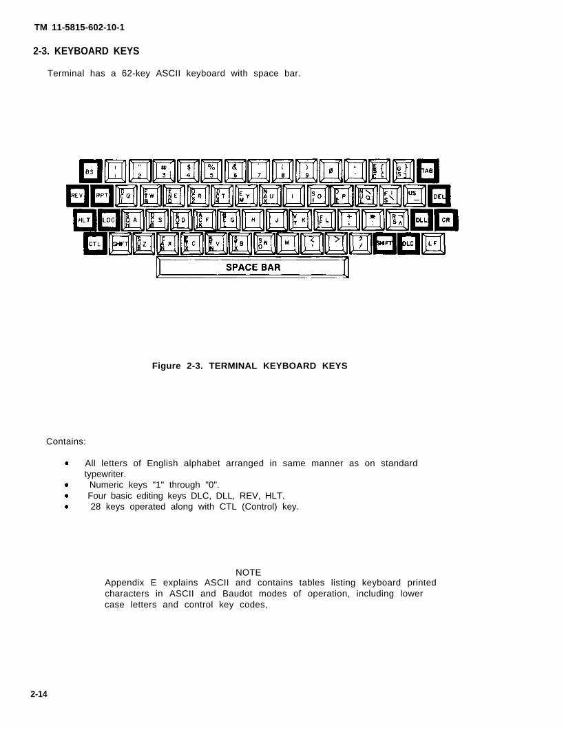
2-3. KEYBOARD KEYS
Terminal has a 62-key ASCII keyboard with space bar.
Figure 2-3. TERMINAL KEYBOARD KEYS
Contains:
All letters of English alphabet arranged in same manner as on standardtypewriter.� Numeric keys "1" through "0".
� Four basic editing keys DLC, DLL, REV, HLT. 28 keys operated along with CTL (Control) key.
NOTEAppendix E explains ASCII and contains tables listing keyboard printedcharacters in ASCII and Baudot modes of operation, including lowercase letters and control key codes,
2-14

TM 11-5815-602-10-1
1. BS2. DC13. ETB4. ENQ5. DC26. DC47. EM8. NAK9. SI10. DLE11. NUL12. ESC13. FS14. GS15. us16. DEL17. CR
Backspace (FE)Device Control 2End of Transmission Block (CC)Enquiry (CC)Device Control 2Device Control 4 (Stop)End of MediumNegative Acknowledge (CC)Shift InData Link Escape (CC)NullEscapeFile Separator (IS)Group Separator (IS)Unit Separator (IS)DeleteCarriage Return (FE)
18. LF19. RS20. FF21. VT22. so23. STX24. BEL25. SYN26. ACK27. ETX28. EOT29. CAN30. SUB31. DC332. SOH33. CTL
Line-Feed (FE)Record Separator (IS)Form Feed (FE)Vertical Tabulation (FE)Shift OutStart of Text (CC)Bell (Audible or attention signal)Synchronous Idle (CC)Acknowledge (CC)End of Text (CC)End of Transmission (CC)CancelDevice Control 3SubstituteStart of Heading (CC)Control Key
NOTESee Appendix E, paragraph E-2 for detailed explanation ofabbreviations (CC), (FE) and (IS), and use of control andgraphic characters.
Meaning of Abbreviations
(cc) Communication Control(FE) Format Effecter(IS) Information Separator(1) In strict sense, DEL is not a control character
2-15
TM 11-5815-602-10-1
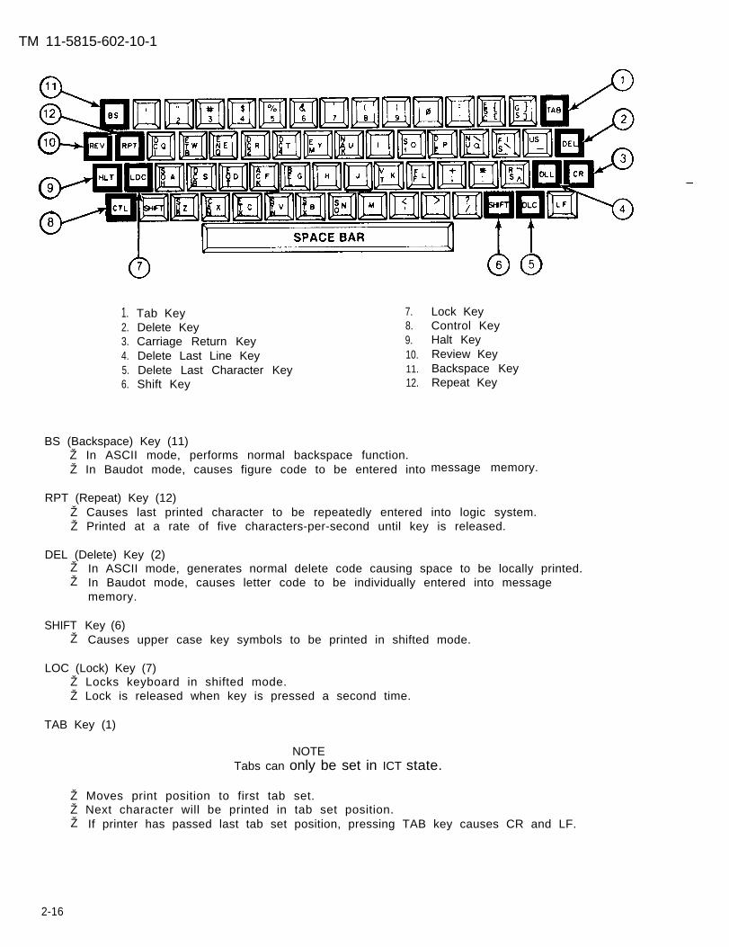
1.2.3.4.5.6.
Tab Key 7.Delete Key 8.Carriage Return Key 9.Delete Last Line Key 10.Delete Last Character Key 11.
Shift Key 12.
BS (Backspace) Key (11)Ž In ASCII mode, performs normal backspace function.Ž In Baudot mode, causes figure code to be entered into
Lock KeyControl KeyHalt KeyReview KeyBackspace KeyRepeat Key
message memory.
RPT (Repeat) Key (12)Ž Causes last printed character to be repeatedly entered into logic system.Ž Printed at a rate of five characters-per-second until key is released.
DEL (Delete) Key (2)ŽŽ
SHIFTŽ
In ASCII mode, generates normal delete code causing space to be locally printed.In Baudot mode, causes letter code to be individually entered into messagememory.
Key (6)Causes upper case key symbols to be printed in shifted mode.
LOC (Lock) Key (7)Ž Locks keyboard in shifted mode.Ž Lock is released when key is pressed a second time.
TAB Key (1)
NOTETabs can only be set in ICT state.
Ž Moves print position to first tab set.Ž Next character will be printed in tab set position.Ž If printer has passed last tab set position, pressing TAB key causes CR and LF.
2-16

TM 11-5815-602-10-1
CR (Carriage Return) Key (3).• Causes print position to move to left-hand margin.
NOTEAfter reaching end of line, entering additional characterautomatically causes CR and LF.
• In KSR state, causes current print line to be transmitted.
NOTEThe following four keys are used by the operator inperforming basic message editing.
DLC (Delete Last Character) Key (5)
Ž Erases incorrect or unwanted characters from memory.Ž Prints backward slash (\) over unwanted character to indicate character has been
erased from message memory.�� Key is only valid on current print line.Ž In ICT state, CR and LF occurs when print position is moved back to left-hand
margin by pressing key.Ž When line length plus one character is entered on current line, CR and LF
occurs and remainder of line is printed.
DLL (Delete Last Line) Key (4)
• Erases current input line from storage.• Terminal responds with CR and LF to indicating current line has been erased.• If no printing occurs on current input line, terminal responds with CR and LF.
REV (Review) Key (10)
• Causes terminal to automatically reprint current input line (before CR is entered)for operator review.
� Additional characters may be added to line following last character.Ž If no printing occurs on current input line, terminal responds with CR and LF.
HLT (Halt) Key (9)
Ž Allows operator to restrict local printing of message being transmitted. However,other messages can be printed from message memory.
.• Operates in ICT state.• Stops any operator-initiated printing.� Terminal responds by printing error message No. 17, PRINTING TERMINATED.� Transmits message while in KSR state.
CTL (Control) Key (8)
Ž Activates keys having control character groups.Ž Used only when terminal is main part of computerized communication system.Ž See Appendix E for detailed instructions on use of Control key and control-
activated keys.
2-17

TM 11-5815-602-10-1
2-4. OPERATIONAL STATES AND NONOPERATIONAL CONDITIONS
The AN/UGC-74B(V)3 or C(V)3 system is composed of three operational states and fivenonoperational conditions
a. Operational states are operator selectable using STATE switch. (See figure 2-5.)These operational states are the only states in which terminal is capable ofoperating as a communications terminal.
Figure 2-5. INTERFACE ASSEMBLY
Operational states are:
Ž Receive Only (RO) state.Ž Keyboard Send/Receive (KSR) state..Ž Intelligent Communication Terminal (lCT) state,
MODEL C ONLY
.Ž Auxiliary Memory/Relay Functions apply only in ICT state.
In each of operational states, terminal is capable of receiving messages. In KSRand ICT operational states, terminal is also capable of transmitting messages.
b, Nonoperational conditions of terminal are:
� OFF Condition (POWER switch in OFF position),❵ Cold Start (power applied to terminal).l Operation Validation/State Determination (system initialized).l Battery Backup (prime power removed),l Self-Test (system readiness check).
c. An explanation of operational states (table(table 2-2) which comprise AN/UGC-74B(V)3
2-1)and
and nonoperational conditionsC(V)3 systems follows.
2-18

TM 11-5815-602-10-1
Table 2-1. OPERATIONAL STATES
RO
STATE
RO
STATE
[1) RECEIVE ONLY (RO) State
Ž�
�
b
Receives messages onlyOperates as buffer for message printing.Stores messages before printing so if data reception speed exceeds printer speedcapability, no message parts are lost.Transmits message BREAK to sending terminal at 85% message memory fullcondition. Removes BREAK at 75% message memory full condition
Received messagestransmitted BREAK
[2) KEYBOARD SEND/RECEIVE
� Transmits and receives messages.
NOTEmay be lost without any indication of loss ifis not recognized by transmitting terminal.
(KSR) State
Ž. Operates in CHARACTER or LINE mode, operator selected.
LINE MODEŽ Sends one line of text (up to 132 characters) after carriage return (CR) key or
halt (HLT) key is activated on keyboard.� Prints received line of text after any one of the following:
A carriage return is found in received text. The line length plus one character is received. A 0.5 to 1,5 second time lapse between received characters is detected.
Ž Basic editing functions keys are available (DLC, DLL, REV).� line mode, system prints AUTOMATIC LINE FEED WITH CARRIAGE
RETURN ? (Y/N). A Y response inserts a line feed with each CR.
CHARACTER MODEŽ Basic editing functions keys are not available.• Transmits each character as it is typed.Ž Prints LOCAL ENTRY PRINT? (Y/N) as operator prompt to select printing of
characters locally as typed, or not echo printed.• Prints received characters as individually received.
NOTESNo automatic LF with CR in either LINE or CHARACTER mode
Does not transmit or interpret communications envelopes in KSRstate.
2-19

TM 11-5815-602-10-1
Table 2-1. OPERATIONAL STATES - Continued
STATE
(3) INTELLIGENT COMMUNICATIONS TERMINAL (lCT) State
� Ž Basic editing function keys are available (DLL, DLC, REV) ,• Recognizes closed communication envelope messages. This recognition causes
Ž MESSAGE RECEIVED lamp to light, which informs opertor that message has beenstored in message memory.
• Prints out messages at operator convenience,Ž Composes, edits and transmits complete messages,• Transmits and interprets communications envelopes, end-of-line sequences and
redundant carriage returns,.• Uses system command functions to compose, edit, and transmit messages,
MODEL C ONLY
� •Transfers message memory messages to Auxiliary Memory Module. •Relays messages from AMM to other AMM-equipped terminals..ŽPerforms additional system commands (paragraph 2-13).
2-20

TM 11-5815-602-10-1
Table 2-2. NONOPERATIONAL CONDITIONS
(1) OFF Condition
Ž Automatically entered whenever the following occurs:❑ Dust cover POWER switch is turned OFF.❑ Primary power fails and no battery backup is provided.
NOTEIf battery backup is provided, system automatically enters BatteryBackup condition if primary power fails and POWER switch is ON.
Ž Primary power input causes this condition to end.
(2) COLD START Condit ion
Ž System “energizing” condition.Ž Message memory is empty.Ž Upon completion of energizing, system prints SYSTEM INITIALIZED.
(3) OPERATION VALIDATION/STATE DETERMINATION Condit ion
● System performs Operation Validation test by determining if keyboard andmessage memory are present, and then determining internal switch settings andtheir combined configuration. Based on this examination, operational state ofterminal is determined and stored in memory.
NOTESIf any combination of switches produces an illegal configuration,terminal prints IMPROPER SWITCH SETTINGS and ignores allinputs. POWER switch must be turned OFF, switches reset, andsystem processed through
Illegal configurations are:ASCII below 75 baudASCII Diphase belowBaudot-Diphase
(4) BATTERY BACKUP Condition
Ž Protects message memory dataŽ Automatically entered whenever
connected to terminal.Ž If no backup battery is presentŽ When Battery Backup condition
this point again.
300 baud
if primary power fails.primary power fails and backup battery is
OFF condition is entered.is entered, BAT lamp lights
Ž No data processing is performed.Ž Printer, keyboard, and interface assemblies are nonoperational.Ž Requires external 14-volt battery.
2-21

TM 11-5815-602-10-1
After corrective action, Self-Test must be repeated for following reasons: • To confirm that fault has been corrected. Ž To test any assemblies not tested previously because of failure.
System power supply is not tested as independent test, but rather by usage
Power supply capability is tested while performing other tests.
Power supply may fail completely when power is applied and Self-Test STARTswitch is activated.
Power supply may partially fail when low voltage is supplied to assemblies. Ž These occurrences must be recognized by operator as system failures.
b. Perform following procedures before starting Self-Test. (See table 2-3.) Ž Release combination case latches.
COMBINATION CASE LATCH
NOTETo release latches, press safety latch located on bottom of rightcombination case latch, and top of left combination case latch.
CAUTION
Use extreme care to ensure connector cables in rear of terminalare carefully pulled through rear opening to prevent damage tocables or connectors.
2-23

TM 11-5815-602-10-1
● Extend terminal forward until slides stop,
EXTENDED POSITION
● INT/EXT/KG-30 CLOCK switch must be in INT position.
CLOCK
● Rotate ILLUM control to BRT and AUDIO control to MAX.
● Set POWER switch in ON position
NOTEPrint head moves to far left position, dust cover lamps flash onmomentarily, copy lamps light, audio alarm sounds momentarily.
● Terminal prints Operation Validation/State Determination message,
NOTERead Normal Test Indication before performing each test. Notifyunit maintenance if there is a test failure indication.
2-24

TM 11-5815-602-10-1
Ž To start test 1, momentarilyassembly to START position.
toggle spring-loaded SELF-TEST switch on interface
Table 2-3. SELF-TEST
TEST
1
2
ASSEMBLIES BEINGCHECKED
Universal CPUCircuit CardAssembly.
Printer ControlCircuit CardAssembly.
NORMAL TESTINDICATION
a.
b.
a.
b.
c,
All dust coverindicator lampsexcept PARITYlamp turn onimmediately.Battery lamp isoff.
2 to 4 secondslater PARITYlamp turns on.
When all indicatorlamps except BATare on pressPARITY RESETswitch tocontinue testing.
All indicatorlamps exceptEND-OF-LINElamp turn off.
Printer printsletter E in all 80print charactercolumns.
TEST FAILUREINDICATION
NOTETerminal will print(if possible) testfailure indication.PARITY lamp doesnot turn on.
PARITY lamp remainsoff or printed errormessage is seen.END-OF-LINE lampremains on and testhalts.
2-25

TM 11-5815-602-10-1
TEST
2
3
MODEL CONLY3A
4
Table 2-3. SELF-TEST - Continued
ASSEMBLIES BEINGCHECKED
Printer ControlCircuit CardAssembly(continued)
Universal CPUCircuit CardAssembly(messagememory test)
CommunicationCircuit CardAssembly
NORMAL TESTINDICATION
d, After executingLF and CR,terminal prints all64 individual printcharacters.PARITY lampturns on.
a, Press PARITYRESET switch tocontinue testing.
NOTETest requires over2 minutes.
b. MEM FULL lamp isonly indicator on.
For MODEL C, seelast entry of thistable.
a, Press PARITYRESET switch tocontinue testing,
b. LINE lamp is onlyindicator on,
c, Standard testpattern is trans-mitted and loopedback through thereceiver. Receivedmessage comparedto transmittedmessage. If two areidentical, terminalprints out message.
TEST FAILUREINDICATION
Message Memoryfailure indicated.
Communicationcircuit card failureindicated.
2-26

TM 11-5815-602-10-1
Table 2-3. SELF-TEST - Continued
TEST
4
5
ASSEMBLIES BEINGCHECKED
CommunicationCircuit CardAssembly(continued)
Keyboard
NORMAL TESTINDICATION
d
e.
a.
b,
c,
PARITY lampturns on at thesame timeprinting begins,
Terminal willtransmit, receive,and print80-charactermessage untilPARITY RESETswitch is pressed.Pressing switchalso causestesting tocontinue.
NOTEIf keyboard is notpresent, testingwill end at thistime,
PAPER LOW lampis only indicatoron.
Terminal printsKEYBOARD TEST,executes one CRand two LF.
PARITY lampturns on.
TEST FAILUREINDICATION
2-27

TM 11-5815-602-10-1
Table 2-3. SELF-TEST - Continued
TEST
5
ASSEMBLIES BEINGCHECKED
Keyboard(continued)
NORMAL TESTINDICATION
d
e
f.
g.
Operator canfreely enterkeyboard char-acters and verifythat proper char-acters are beingprinted. Keyboardis functioningproperly ifprintout agreeswith what wastyped on key-board.
Operator endsSELF-TEST bypressing PARITYRESET switch.
Terminal willprint READY,then automaticallyprints outoperational statemessage,
NOTEIf it becomesnecessary tochange INT/EXT/KG-30 CLOCK setPOWER switch inOFF position, andreset switch,Reapply power bysetting POWERswitch in ONposition,
After completingtest, turn POWEROFF. Returnterminal to caseand secure com-bination caselatches.
TEST FAILUREINDICATION
2-28

TM 11-5815-602-10-1
MODEL C ONLY AM/RF SELF-TEST
Table 2-3. SELF-TEST - Continued
NOTEIn MODEL C test sequence, these tests are performed aftertest 3 (Universal CPU) and before test 4 (Communication).
ASSEMBLIES BEING NORMAL TEST TEST FAILURETEST CHECKED INDICATION INDICATION
3A Auxiliary a. MSG RCVD lamp One of followingInterface turns on and all messages will beCircuit Card other lamps turn printed according toAssembly off. failed tested item:
AM/RC Circuit b. After 15 seconds, AM/RFCard Assembly PARITY lamp INTERFACE
turns on. FAILURE
Auxiliary c. Press PARITY MAINTENANCEMemory Module RESET switch to NOTE: ROM TEST
continue testing. FAlLED (A2A4)
MAINTENANCENOTE: RAM TESTFAlLED (A2A4)
MAINTENANCENOTE: RTC TESTFAlLED (A2A4)
AUXILIARYMEMORY MODULEERROR
MAINTENANCENOTE: SCC ORRELAY TEST
NOTE FAILED (A2A4)Testing procedurecontinues as listed at When message istest 4 of this table. printed, system halts
and only MSG RCVDlamp is on.
NOTEAM/RF See TST command insubsystem Appendix F, para -special test graph F-20.
{
2-29

TM 11-5815-602-10-1
Section Il.
2-6. GENERAL
PREVENTIVE MAINTENANCE CHECKS AND SERVICES (PMCS)
Operator preventive maintenance is the systematic care, servicing and inspection ofequipment to prevent the occurrence of trouble, to reduce downtime, and to keepequipment in good operating condition.
a. Systematic care procedures given in table 2-4 explain routine, systematic careand cleaning essential to proper upkeep and operation of the terminal.
b. Preventive Maintenance Checks and Services (PMCS) described in table 2-4outline functions to be performed at specific times. These checks and servicesare to maintain telecommunications equipment in good, general (physical)condition and in good operating condition. To assist operators in maintainingcombat serviceability, the table indicates what to check, how often, how tocheck, and what conditions will cause quipment not to be “ready” (for readinessreporting purposes). • Records and reports of these checks and services must be made in accordance
with requirements set forth in DA PAM 738-750.
NOTEAlways keep in mind all CAUTIONS and WARNINGS whenperforming PMCS.
Ž Before operating - perform before (B) PMCS.Ž While operating - perform during (D) PMCS.Ž After operating - perform after (A) PMCS.Ž If equipment fails to operate, troubleshoot using table 3-1. Report any
deficiencies to unit maintenance using proper forms as specified inDA PAM 738-750.
c. Periodic checks and services in table 2-4 specify checks and services that mustbe performed by operator as specified in Interval Column under the followingspecial conditions:ŽWhen equipment is initially installed,Ž equipment is maintained in standby condition (ready for immediate
operation, perform PMCS monthly,Ž When equipment is reinstalled after removal for any reason.
If equipment must be kept in continuous operation, check and service onlythose items that can be checked and serviced without disturbing operation.
Make complete checks and services when equipment can be shut down.
Within designated intervals, checks are to be performed in order listed:
B - Before operatingD - During operationsW - WeeklyM - Monthly
Deficiencies noted beyond operator capability to correct are to be reported tounit maintenance.
2-30

TM 11-5815-602-10-1
d. Special Instructions –
Perform monthly maintenance procedures as indicated in table 2-4 at least oncea month. For purposes of this manual, a month is defined as approximately 30calendar days of 8-hour-a-day operation. If equipment is operated more than 8hours per day, monthly maintenance intervals should be adjusted as follows:
Hour-a-Day Operation Monthly PMCS Required (calendar days)
8 3016 1524 10
Equipment in limited storage (maintenance service required before beingoperated) does not require PMCS.
Routine checks like equipment inventory, cleaning, dusting, washing, checkingfor frayed cables, stowing items not in use, covering unused receptacles, andchecking for loose nuts and bolts are not listed as PMCS checks. These thingsshould be done any time the need arises. Routine checks listed in PMCS arebecause other operators reported problems with this item.
When doing PMCS or routine checks, keep in mind WARNINGS and CAUTIONS.
2-7. OPERATOR PREVENTIVE MAINTENANCE CHECKS AND SERVICES TABLE (table 2-4)
NOTEIf operating terminal for first time, or terminal has not beenoperated since last weekly check, perform weekly as well asbefore operations PMCS.
2-31
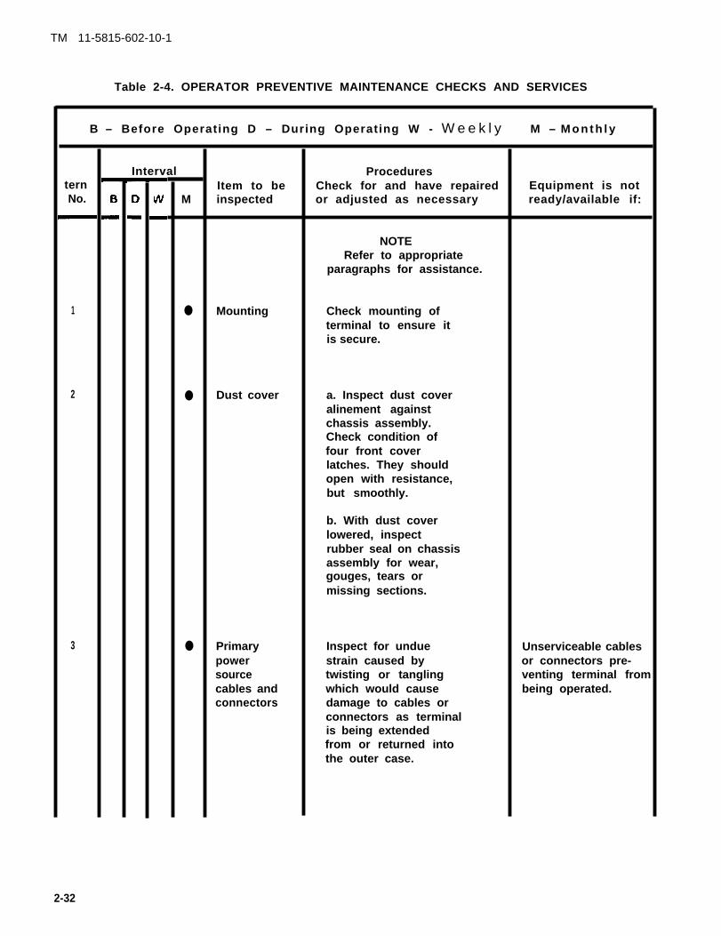
Table 2-4. OPERATOR PREVENTIVE MAINTENANCE CHECKS AND SERVICES
B – Before Operating D – During Operating W - W e e k l y
ternNo.
1
2
3
Interval
M
●
●
●
Item to beinspected
Mounting
Dust cover
Primarypowersourcecables andconnectors
ProceduresCheck for and have repairedor adjusted as necessary
NOTERefer to appropriate
paragraphs for assistance.
Check mounting ofterminal to ensure itis secure.
a. Inspect dust coveralinement againstchassis assembly.Check condition offour front coverlatches. They shouldopen with resistance,but smoothly.
b. With dust coverlowered, inspectrubber seal on chassisassembly for wear,gouges, tears ormissing sections.
Inspect for unduestrain caused bytwisting or tanglingwhich would causedamage to cables orconnectors as terminalis being extendedfrom or returned intothe outer case.
M – M o n t h l y
Equipment is notready/available if:
Unserviceable cablesor connectors pre-venting terminal frombeing operated.
2-32
TM 11-5815-602-10-1

TM 11-5815-602-10-1
Table 2-4. OPERATOR PREVENTIVE MAINTENANCE CHECKS AND SERVICES - Continued
B - Before Operating D - During Operating W - Weekly
ItemNo.
4
5
6
Interval
MItem to beinspected
Caseinterior
Printerprintingquality
Papersupply
ProceduresCheck for and have repairedor adjusted as necessary
a. Release combinationcase latches and care-fully extend terminalfrom outer case.
(1) Terminal shouldslide smoothly outfrom outer case tostop locks.
(2) If terminal hangsor fails to slidesmoothly, check fordirt, burrs, or otherobstructions.
b. Clean case interiorof oil, dust, grease,moisture, or fungus.
c. Clean interior ofterminal with a longhandle sash orcamel-hair brush.
Check quality ofprinter printing byinspecting messagecopy for readability.
Inspect for adequacyof paper supply.Replenish inaccordance withinstructions containedin paragraph 3-5.
M - Monthly
Equipment is notready/available if:
Excessive dirt, dust,grease, moisture, orfungus would preventterminal from oper-ating properly, or,if operated, wouldcause possible damageor malfunctioning ofterminal.
Message copy isunreadable.
Paper is not available

TM 11-5815-602-10-1
Table 2-4. OPERATOR PREVENTIVE MAINTENANCE CHECKS AND SERVICES - Continued
B - B e f o r e O p e r a t i n g D - D u r i n g O p e r a t i n g W – Weekly M - M o n t h l y
Interval ProceduresItem Item to be Check for and have repaired Equipment is notNo. B D w M inspected or adjusted as necessary ready/available if:
7 Ž Inking Inspect inking ribbon Inking ribbon is notribbon for signs of fraying, available.
wear, dryness orunserviceability.Replace, if necessary,in accordance withinstructions containedin paragraph 3-7a.Check printer quality,PMCS Item No. 5.
8 Ž Backup Perform batterybattery preconditioning as(if present) directed in
paragraph 3-10.Turn POWER OFF,return terminal backinto case, and securelatches.
MODEL C ONLY
1 Ž Captive Inspect screw threads Captive knurledknurled for signs of wear. screws arescrews stripped.
2 Ž Connector Inspect connector for Unserviceable con-P1 bent or missing pins. nector preventing
Auxiliary MemoryModule from beingattached.
3 Ž Connector Inspect connector for Unserviceable con-J1 plugged pin holes. nector preventing
Auxiliary MemoryModule from beingattached.
2-34

TM 11-5815-602-10-1
Section Ill. OPERATION UNDER USUAL CONDITIONS
2-8. PRELIMINARY STARTING PROCEDURES
a. Following procedures must be accomplished before applying power to terminal.
Ž Check that POWER switch is in OFF position.Ž Check that primary power cable is connected to primary power source, and to J2
power connector located on rear panel.
to J1 connector located on rear panel.Ž Check that backup cable is connected to
that backup cable connector is connectedsuitable 14-volt dc power source. Checkto J3 connector located on rear panel.
Ž Check that ground strap is attached to nay low-resistance ground connector andto ground lug (E1) located on rear panel.
NOTEGround strap should be at least 14 AWG size wire long enough toallow opening of terminal.
Ž Check that J1 clock and Data connector is connected to suitable signal line, and
2-35

TM 11-5815-602-10-1
b. If copyholder is not mounted on terminal, install it using following procedures:
Ž Remove copyholder with mounting screw knob from front case cover storagecompartment.
� Ž Unfold two hinged sections to form one flat plane section.
Ž Secure hinged sections to center section by closing four rotating clips located at
Ž
each of center sections.
MOUNTING SCREW
Insert copyholder mounting bracket screw (centerthreaded hole (press fitted nut) located on upper
1
MOUNTING BRACKET I I
section, left side) intoright-hand side of dust cover.
Ž Secure copyholder in place by tightening mounting screw in clockwise direction.
CAUTION
During operation requiring lowering of dust cover, removecopyholder to prevent damage.
2-36

TM 11-5815-602-10-1
c. Check paper supply, [f low, replenish it (paragraph 3-4).
d. Check ribbon, [f frayed, dry or torn, replace it (paragraph 3-7).
NOTENo lubrication is required by the operator.
MODEL C ONLY
e. Install Auxiliary Memory Module using following procedures:
.Ž Position AMM as shown below,
P1
Ž
ŽŽ
Insert locking bracket into hole on front of AMM and aline captive knurled-headscrews with screw holes.Insert plug P1 into connector J1 on right side of keyboard housing assembly.Alternately screw captive knurled-head screws into keyboard housing assemblyuntil both screws are finger tight.
f. Connect relay port cable to left-handbe part of a local relay network.
keyboard assembly connector if terminal is to
2-37

TM 11-5815-602-10-1
2-9. OPERATING PROCEDURES
a, Operational States
Ž Because of capabilities and limitations of each state, procedures and systemcontrols available to operator vary. internal control switches for each of thesestates are shown in figure 2-6,
� Ž Combined settings of these controls and switches, in conjunction with terminalconfiguration, determine operating state of system.
b. After system has been prepared for starting, operator must set terminal switchesand controls. Terminal may be operated in each of following operating states:
Ž Receive Only (RO) state. Ž Keyboard Send/Receive (KSR) state. Ž Intelligent Communications Terminal (lCT) state,
Each state is explained in table 2-1.
NOTEExample shown in following paragraphs c and d is for typicalterminal installation. Operator normally receives presetinstructions from unit Standard Operating Procedure (SOP) orCommunications-Electronics Operation Instructions (CEOI).
c. In following example, terminal is installed in link having requirements listed below:
Ž PARITY: Odd Ž STATE: RO, KSR, or ICT, depending on requirement. Ž COMMUNICATIONS INTERFACE: LO DATA Ž DATA FORMAT: NRZ Ž TRANSMISSION SPEED: 1200 Baud Ž COMMUNICATION CLOCK SOURCE: Internal Ž CLOCK EDGE: Positive (+) Ž FIGURE S/J: Not applicable in ASCII Ž DATA INPUT: Noninverted input Ž NO. OF STOP BITS IN DATA FORMAT: TW O
Ž DATA CHARACTER SET: ASCII
d. With terminal fully extended on slides, perform following initialization setupprocedure for the above example,
CAUTION
Be sure that rear connecting cables feed through terminal rearaccess door with minimum of strain.
2-38

TM 11-5815-602-10-1
With power off, set internal switches as follows.
Figure 2-6. INTERNAL CONTROL
Ž PARITY to ODD� STATE to RO, KSR, or ICT, depending on
SWITCHES/SETTINGS
requirement
Ž REC MODE to LO DATA • XMIT MODE to LO DATA Ž BAUD RATE to 1200 Ž CLOCK INT/EXT/KG-30 to Ž CLOCK +/- to (+)
INT
NOTEFIG S/J is not applicable to ASCII.
Ž SIGNAL NRZ/D1Ø to NRZ� • STOP BITS to 2 • ASC1l/BAUDOT MODE
Set front panel switches as
to ASCII
follows:
• TRANSFER to OFF Ž ILLUM control to BRT� • AUDIO control to MAX
2-39

TM 11-5815-602-10-1
e. During Operationrecords
Validation/State Determination condition, system checks andin memory switch settings that were set before power was applied,
CAUTION
Settings changed without turning POWER OFF may affectoperation of terminal,
• To change operation of terminal with switch settings, POWER must be turnedOFF, switches set, and POWER turned ON.
• Changing setting of following switches with POWER ON will affect terminaloperation. BAUD RATE REC MODE XMIT MODE SELF-TEST SIGNAL NRZ/D1Ø CLOCK INT/EXT/KG-30 CLOCK +/–
• Changing setting of following switches with POWER ON will not affect terminaloperation,I PARITY STOP BITS ASCII/BAUDOT MODE IGURES S/J
• By Operation Validation/State Determination condition message, operator canverify that terminal will function in operational state designated.
• Following is an example of an actual Operation Validation/State Determinationcondition message printout when terminal is in Baudot mode of operation.
SYSTEM INITIALIZED
SOFTWARE SYSTEM CONFIGURATION = UGC-74BWITCH STATE = KSROPERATIONAL STATE = KSRMODE = BAUDOTBAUD RATE = 1200STOP BITS = 2BELL OPTION = FIGURES J DUPLEX MODE = FULLSPACE OPTION = ONLINE LENGTH = 080LINE FEEDS = 1FONT = 1 ENG 64 CHARLINES PER PAGE = 066NJMBER OF PRINT COPIES = 1CHARACTER OR LINE TRANSMISSION ? (C/L)
2-40

TM 11-5815-602-10-1
Ž Following is an example of an actual Operation Validation/State Determinationcondition message printout when terminal is in ASCII mode of operation.
SYSTEM INITIALIZED
SOFTWARE SYSTEM CONFIGURATION = UGC-748SWITCH STATE = KSROPERATIONAL STATE = KSRMODE = ASCI IBAUD RATE = 1200STOP BITS = 1PARITY OPTION = ODDDUPLEX MODE = FULLSPACE OPTION = OFFCAPITAL LETTER OPTION = ONLINE LENGTH = 080LINE FEEDS = 1FONT = 1 ENG 64 CHARLINES PER PAGE = 066NUMBER OF PRINT COPIES = 1CHARACTER OR LINE TRANSMISSION ? (C/L)
2-10. RECEIVE ONLY (RO) OPERATING PROCEDURES
Operation in RO state should be performed in following manner:
● Perform preliminary starting procedures described in paragraph 2-8.● Set initial switch settings as described in paragraph 2-9d.Ž Set STATE switch in RO state position.● All received messages are passed through message memory before printing.● Following is an example of an actual Operation Validation/State Determination
condition message printout when terminal is in RO state, based on example givenin paragraph 2-9d.
SYSTEM INITIALIZED
SOFTWARE SYSTEM CONFIGURATION = UGC-74BSWOTCJ STATE = ROOPERATIONAL STATE = ROMODE = ASCIIBAUD RATE = 1200STOP BITS = 2PARITY OPTION = ODDDUPLEX MODE = FULLSPACE OPTION = OFFCAPITAL LETTER OPTION = ONLINE LENGTH = 080LINE FEEDS = 1END OF MESSAGE LINE FEEDS = 020FONT = 1 ENG 64 CHARLINES PER PAGE = 066NUMBER OF PRINT COPIES = 1
2-41

TM 11-5815-602-10-1
CAUTION
If self-test is to be performed, it should be initiated afterOperation Determination/State Determination message has beenprinted out and before message data is stored in message memory.
Ž After completing operations, be sure all printing has stopped, then set POWERswitch in OFF position.
2-11. KEYBOARD SEND/RECEIVE (KSR) OPERATING PROCEDURES
a. KSR state expands capability of terminal from Receive Only state by makingkeyboard available to operator.
Ž Messages are composed in conventional manner.Ž Terminal provides capability of sending messages one print line at a time.Ž Allows composing, editing and review of full 80-character line of message before
transmission. (Line length may equal 132 characters.)Ž Allows single character mode of transmission.Ž Allows Iocal printing of operator input, operator selectable.Ž Allows operator selection of machine insertion of line feeds with CR’s.
Data is transmitted by either of the three following procedures:
Ž Initiating a carriage-return.Ž Moving print position to line length plus one character of current print line
which automatically causes a carriage-return.Ž Pressing HLT key.
b. In KSR state, three basic keys are available to operator:
Ž Delete Last Character (DLC) key.Ž Delete Last Line (DLL) key.Ž Review (REV) key.
See paragraph 2-3 for a detailed explanation of these keys.
2-42

TM 11-5815-602-10-1
c, Operation in KSR state
Ž Operation Validation/State Determination will show switch position. Ž Keyboard may now be used to send messages. � ❵� Following is an example of an actual Operation Validation/State Determination
condition message printout when terminal is in KSR state, based on examplegiven in paragraph 2-9d.
SYSTEM INITIALIZED
SOFTWARE SYSTEM CONFIGURATION = UGC-74BSWITCH STATE = KSROPERATIONAL STATE = KSRMODE = ASCIIBAUD RATE = 1200STOP BITS = 1PARITY OPTION = ODDDUPLEX MODE = FULLSPACE OPTION = OFFCAPITAL LETTER OPTION = ONLINE LENGTH = 080LINE FEEDS = 1FONT = 1 ENG 64 CHAR LINES PER PAGE = 066NUMBER OF PRINT COPIES = 1CHARACTER OR LINE TRANSMISSION ? (C/L)
After printout, terminal is in KSR state and ready for message reception ortransmission.
After character or line (C/L) transmission is requested, and line (L) is selected,terminal requests line feed insertion choice (Y/N) by the operator.
CAUTION
If self-test is to be performed, it should be initiated afterOperation Validation/State Determination message has beenprinted out and before message data is stored in message memory.
2-12. INTELLIGENT COMMUNICATIONS TERMINAL (lCT) OPERATING PROCEDURES
a. Intelligent Communications Terminal (lCT) state provides operator with composing,editing and formatting capabilities, These capabilities are gained by using SystemCommands Structure shown in figure 2-7, See paragraph 2-14 for commanddescriptions,
2-43

MODEL C ADDITIONALSYS TEM COMMANDS
Figure 2-7. SYSTEM COMMANDS STRUCTURE
• Upon entering ICT state, terminal becomes a word processormessage terminal,
• As a word processor, ICT state performs the following:
as well as a
q Allows operator to enter text of message into term-inal message memory,q Allows operator to add to, or subtract from (edit) text without preparing tape
or written copy.q Series of typed commands must be used in order for terminal to carry out
word processing functions,
2-44
T M 1 1 - 5 8 1 5 - 6 0 2 - 1 0 - 1

TM 11-5815-602-10-1
• System Commands are series of command levels in ICT state used in following:
Editing and sending single line messages without using message memory. Entering PARAMETER and EDIT levels of subcommands for specifying system
parameters and for editing. Obtaining status of messages in message memory and terminal itself.
b. Operation in ICT state.
• Same setup procedures as RO and KSR state when system is powered down.Ž STATE switch is set in ICT state and system is powered up.Ž Operation Validation/State Determination message shows switch positions .• Switch settings given in paragraph 2-9d used for this example.• Message transmission is carried out after message has been composed, edited, and
reviewed.• Completed message is sent by using TRANSMIT system command.Ž A “home copy” of each message transmitted is printed by terminal.
NOTEIn this state, operator also has option of sending a single linemessage (up to 80 characters) as in KSR state. Additionally,single line messages may be lengthened to 132 characters in ICTstate. See LINE subcommand under PARAMETER command.
l• Following is an example of an actual Operation Validation/State Determinationcondition message printout when terminal is in ICT state, based on example givenin paragraph 2-9d.
SYSTEMI INITIALIZED
SOFTWARE SYSTEM CONFIGURATION = UGC-74BSWITCH STATE = ICTOPERATIONAL STATE = ICTMODE = ASCIIBAUD RATE = 1200STOP BITS = 2PARITY OPTION = ODDDUPLEX MODE = FULLEND OF LINE OPTION = CR CR LFRECEIVE ENVELOPE OPTION =
v Z C Z C: N N N NTRANSMIT ENVELOPE OPTION =
V Z C Z C: N N N N DE DE DE DE DE DE DE DE DE DE DE DESPACE OPTION = OFF CAPITA LETTER OPTION = ONLINE LENGTH = 080 LINE FEEDS = 1END OF MESSAGE LINE FEEDS = 020FONT = 1 ENG 64 CHARLINES PER PAGE = 066NUMBER OF PRINT COPIES = 1
CAUTION
If self-test is to be performed, it should be initiated afterOperation Validation/State Determination message has beenprinted out and before message data is stored in message memory.
2-45

TM 11-5815-602-10-1
MODEL C ONLY
Following is an example of an actual Operation Validation/State Determinationcondition message printout when terminal is in ICT state, based on example givenin paragraph 2-9d.
SYSTEM INITIALIZED
SOFTWARE SYSTEM CONFIGURATION = UGC-74CSWITCH STATE = ICT OPERATIONAL STATE = ICTMODE = ASCII BAUD RATE = 1200STOP BITS = 2fPARITY OPTION = ODDDUPLEX MODE = FLLLEND OF LINE OPTION = CR CR LFRECEIVE ENVELOPE OPTION =
V Z C Z C: N N N NTRANSMIT ENVELOPE OPT ION =
V Z C Z C: N N N N DE DE DE DE DE DE DE DE DE DE DE DESPACE OPTION = OFFCAPITAL LETTER OPTION = ONLINE LENGTH = 080LINE FEEDS = 1END OF MESSAGE LINE FEEDS = 020FONT = 1 ENG 64 CHAR LINES PER PAGE = 066 NUMBER OF PRINT COPIES = 1AUTO SAVE OPTION = ONAUTO PRINT OPTION = OFFNOFORM OPTION = ON
HELP COMMAND AVAILABLE
99% AMM MEMORY AVAILABLE
CAUTION
If self-test is to be performed, it should be initiated afterOperation Validation/State Determination message has beenprinted out and before message data is stored in message memory.
2-13. ICT STATE OPERATING INSTRUCTIONS
This paragraph describes all operating functions of terminal in ICT state whichoperator must know in order to understand why terminal responds to various operatinginstructions.
a. System abbreviations are used in this manual to quickly illustrate operator input orterminal output. Meaning of abbreviations are contained in table 2-5.
2-46

TM 11-5815-602-10-1
Table 2-5. SYSTEM ABBREVIATIONS
Abbreviation Meaning
CR . . . . . . . . . . . . . . . Carriage-Return
LF . . . . . . .. Line-Feed
C R / L F . . . Used in this manual to signify blank line and start of printingat left margin.
b0 . . . . . . . . . . . . . . . Specifies that no spaces between characters are required, butas many as desired may be entered optionally.
bl . . . . . . . . . . . . . . . Specifies that only one space is required.
b2 . . . . . . . . . . . . . . . Specifies that at least one space is required but more than oneis allowed.
xxxx . . . . . . . . . . . A four-digit (decimal) message identification number that mayor may not contain leading zeros, and may or may not containleading blanks. The count starts with 1 and ends with 999.
xxx . . . . . . . . . . . . A three-digit (decimal] number that may or may not containleading zeros. The count starts with 1 and ends with 999.
xx . . . . . . . . . . . . . . . A two-digit (decimal) number that may or may not contain aleading zero or a leading blank (01 or 1 is acceptable). Countstarts with 1 and ends with 99,
x . . . . . . . . . A one-digit (decimal) number. Count starts with 1 and endswith 9.
(?) . . . . . . . . . . . . . . . Indicates that specification contained within parentheses isoptional.
(+) . . . . . . . . . . . . . . . Indicates that several options are available, one of which mustbe chosen,
( # ) . . Indicates that specification within parentheses may be invokeda number of times,
Line Pointer.. Always points to first character of current line. Line pointer isa memory indicator and is not visually displayed on terminal.
A . . . . . . . . . . . . . . . ASCII character(s).
Delimiter . . . . . . . Any ASCII character used as space or separator. It cannotappear in same character string for which it is a delimiter.
** . . . . . . . . . . . . . . . Used in command to imply all options.
Operand . . . . . . . . One or more ASCII characters used in command to amplifyinstructions.
NULL . . . . . . . . . . . . Nothing is entered in a particular operand field (CR).
2-47

TM 11-5815-602-10-1
b. The AN/UGC-74B(V)3 and C(V)3 have the ability to indicate errors or exceptionconditions by printing error messages or prompting messages.
● List of error messages appears in table 2-6 and in Appendix J.Ž Prompting messages are not printed with message number and are preceded by an
asterisk (*) in Error Message List.
Sequence of printing error messages is for terminal to initiate following:
Ž Carriage-Return (CR) and Line-Feed (LF).Ž Error message number and error message, followed by CR and LF.● Terminal returns to System Command Level
NOTEError message does not necessarily mean that ancould indicate a function has been performed andprinted.
Table 2-6. ERROR MESSAGE LIST
error exists, butthe message is
NUMBER
(1)
(2)
(3)
(4)
(5)
(6)
(7)
(8)
(9)
( l 0 )
(11)
(12)
(13)
*(14).
2-48
MESSAGE
NOT REMOVED, COMM PORT “RECEIVE” MESSAGE NEVER PRINTED
MESSAGE NOT FOUND
INTERNAL MESSAGE MEMORY FILLED
PHRASE NOT FOUND
DELIMITER/PHRASE IN ERROR
COMMAND NOT ACCEPTED, CURRENT LINE TOO LONG, CHANGELINE PARAMETER
MESSAGE EMPTY
MAXIMUM NUMBER OF HEADER LINES EXCEEDED
USE 12 TABS MAXIMUM
INVALID OR MISSING COMMAND VARIABLE
COMMAND NOT ACCEPTED, COMMUNICATIONS PORT BUSY
COMMAND INPUT NOT RECOGNIZED
COMMAND NOT ACCEPTED, IMPROPER IN PRESENT COMMAND MODE
ARE YOU SURE? (Y/N)

TM 11-5815-602-10-1
Table 2-6. ERROR MESSAGE LIST - Continued
N UMBER
(15).
(16).
(17).
(18).
(19).
(20).
(21).
(22).
(23).
(24).
(25).
*(26).
*(27).
*(28).
(29).
(30).
*(100).
*(101).
*(102).
*(103).
MESSAGE
Not Used
“COMPOSED” MESSAGE HAS NOT BEEN TRANSMITTED
PRINTING TERMINATED
MESSAGE XXXX REMOVED FROM INTERNAL MESSAGE MEMORY
COMMAND NOT ACCEPTED, MESSAGE IS CURRENTLY INTRANSMISSION ON COMM PORT
NO TABS SET
IMPROPER MESSAGE HEADER FORMAT
INPUT IGNORED, LINE LENGTH UNACCEPTABLE
NO HEADER DEFINED
INCORRECT TIME-OF-DAY, MUST BE 4 DIGITS
COMMAND NOT ACCEPTED, INCORRECT HEADER SELECTION
CHANGE SWITCH SETTINGS AND ENTER CR TO CONTINUE
CHARACTER OR LINE TRANSMISSION? (C/L)
LOCAL ENTRY PRINT? (Y/N)
FONT NOT AVAILABLE
ALIGN PAPER AND ENTER CR TO CONTINUE
NOTEMessage Numbers 31 through 99 are reserved forAN/UGC-74C(V)3 and are listed at the end ofAN/UGC-74B(V)3 messages.
ENTER CHANNEL IDENTIFIER
ENTER ORIGINATOR ROUTING INDICATOR/PLAIN LANGUAGEADDRESS (R1/PLA)
ENTER MESSAGE PRECEDENCE
ENTER ORIGINATOR AND DESTINATION LANGUAGE AND MEDIAFORMAT
2-49

TM 11-5815-602-10-1
Table 2-6. ERROR MESSAGE LIST - Continued
NUMBER
*(104)
* (105),
*(106)
*(107)
*(108)
*(109)
*(11O)
* (111).
* (112).
* (113),
*(114).
*(115)
* (116).
(117),
(118).
(119).
(120).
(121).
*(122)
* (123).
*(124)
(125).
MESSAGE
ENTER CLASSIFICATION
ENTER CONTENT INDICATOR/COMMUNICATION ACTION IDENTIFIER
ENTER STATION SERIAL NUMBER
ENTER JULIAN DATE
ENTER TIME FIELD
ENTER ACTION ROUTING INDICATOR/PLAIN LANGUAGE ADDRESS(R1/PLA)
ENTER INFORMATION ROUTING INDICATOR/PLAIN LANGUAGEADDRESS (R1/PLA)
ENTER TIME OF DAY (ZULU TIME)
ENTER DAY, MONTH, AND YEAR
ENTER CHANNEL SEQUENCE NUMBER
ENTER EXEMPT ROUTING INDICATOR/PLAIN LANGUAGE ADDRESS(R1/PLA)
ENTER SECURITY PROSIGN
ENTER SECOND PRECEDENCE
NO MORE ROOM FOR
NO MORE ROOM FOR
NO MORE ROOM FOR
NO MORE ROOM FOR
NOT ENOUGH ROOMEXISTING R1/PLA
JANAP 128
ACP 127 USA SUPP 1
ACP 127 NATO SUPP
ORIGINATOR R1/PLA
ACTION R1/PLA
INFORMATION R1/PLA
EXEMPT R1/PLA
IN NEW HEADER VARIABLE FOR ALL OF
COMMAND INVALID FOR BAUDOT
2-50
3

TM 11-5815-602-10-1
Table 2-6. ERROR MESSAGE LIST - Continued
NUMBER
(126).
(127)
(128).
(129).
(130)
*(131)
(132).
(133).
*(134)
*(135)
MESSAGE
COMMAND NOT ACCEPTED, MESSAGE IN RECEIVE CATEGORY
IMPROPER SWITCH SETTING - ASCII AT LESS THAN 75 BAUD
Not Used
IMPROPER SWITCH SETTING - D1Ø AT LESS THAN 300 BAUD OR INBAUDOT
IMPROPER SWITCH SETTING - D1Ø WITH EXTERNAL CLOCK
MEMORY XX% FULL
WARM START ABORTS ALL COMM LINE ACTIVITY
BACKSPACE NOT ALLOWED
HELP COMMAND AVAILABLE
AUTOMATIC LINE FEED WITH CARRIAGE RETURN ? (Y/N)
MODEL C ONLY ADDITIONAL ERROR MESSAGES
(31).
(32).
(33)
(34).
(35).
(36).
(37).
(38).
(39).
(40].
(41).
(42).
(43).
COMMAND NOT ACCEPTED, AUTOSAVE MUST BE ON
RELAY MESSAGE #XXXX IN PROGRESS
CANNOT RELAY, NO CHANNEL ASSIGNED
NOT ASSIGNED, CHANNEL MUST BE IN 1-16 RANGE
RELAY MESSAGE #XXXX CHANNEL #XX NOT SAVED
AUXILIARY MEMORY MODULE NOT ACCESSIBLE
AUXILIARY MEMORY MODULE ERROR
CONNOT DESIGNATE AS MASTER, CHANNEL ALREADY ASSIGNED
INSUFFICIENT AUXILIARY MEMORY TO SAVE MESSAGE
MESSAGE NOT FOUND; CHECK NAME
DUPLICATE NAME; SEQUENCE LETTER ADDED
ALL RELAYED MESSAGES HAVE BEEN ACCESSED
CATALOG EMPTY
2-51

TM 11-5815-602-10-1
Table 2-6. ERROR MESSAGE LIST - Continued
NUMBER MESSAGE
MODEL C ONLY ADDITIONAL ERROR MESSAGES - Continued
(44).
(45).
(46).
(47).
(48).
(49).
(50).
(51).
(52).
(53).
(54).
(55).
(56).
(57).
(58).
(59).
(60).
(61).
(62).
(63).
(64).
(65).
CANNOT XMIT TO CHANNEL #XX
RELAY MESSAGE #XXXX CANCELED
RELAY MESSAGE #XXXX CANCELED
OLD MESSAGE NAME NOT FOUND
IN PROGRESS
NEW MESSAGE NAME ALREADY EXISTS
AUXILIARY MEMORY MODULE FULL
MESSAGE NOT SAVED, NO MORE SEQUENCE INDICATORS AVAILABLEFOR DUPLICATE NAME
COMPLETED RELAY MESSAGE #XXXX
NOT ASSIGNED, ANOTHER CHANNEL IS MASTER
RELAY CHANNEL ACTIVATED
RELAY CHANNEL NOT ACTIVE
RELAY CHANNEL #XX REQUEST IN PROGRESS
NOT ASSIGNED, CHANNEL #XX ALREADY USED
COMMAND NOT ACCEPTED, MESSAGE RELAY IN
RELAY MESSAGE #XXXX PREPARED
TEST NOT ALLOWED; RELAY CHANNEL ACTIVE
MAINTENANCE NOTE: AMRF
MAINTENANCE NOTE: AMRF
MAINTENANCE NOTE: AMRF
MAINTENANCE NOTE: AMRF
COMMAND NOT ACCEPTED,
PROGRESS
RAM TEST FAlLED (A2A4)
ROM TEST FAILED (A2A4)
RELAY TEST FAlLED (A2A4)
RTC TEST FAlLED (A2A4)
AUX MEMORY
AUX MEMORY AND RELAY FUNCTION NOT
RELAY BUSY
OPERATING
2-52

TM 11-5815-602-10-1
Table 2-6. ERROR MESSAGE LIST - Continued
NUMBER MESSAGE
MODEL C ONLY ADDITIONAL ERROR MESSAGES - Continued
(66).
(67).
(68).
(69).
* (70).
*(71)
*(72)
*(73)
* (74).
(75).
(76).
(77).
(78).
(79).
(80).
(81).
(82).
(83).
(84).
(85).
(86).
(87).
AM/RF INTERFACE FAILURE
AUTO SAVE ENABLED
AUTO SAVE SUSPENDED
A1A2 FAILURE
MESSAGE NUMBER
LOW PRECEDENCE
HIGH PRECEDENCE
LOW PRECEDENCE
HIGH PRECEDENCE
XXXX IS NAMED XXXXXX,X
NONPRINTED MESSAGES IN
NONPRINTED MESSAGES IN
MESSAGE MEMORY
MESSAGE MEMORY
NONACCESSED
NONACCESSED
MESSAGES ON AMM
MESSAGES ON AMM
NO RELAY MESSAGE TO CANCEL
AMM COMMAND
RELAY ADDRESS
Not Used
ERROR
ERROR -- SCC OR RAM ERROR
MASTER CHANNEL SELECT ENABLED
RELAY MESSAGE SIZE LIMIT EXCEEDED, RE-EDIT
CANNOT ACTIVATE MASTER CHANNEL, RAM ERROR
MASTER CHANNEL SELECT DISABLED
CANNOT SORT, TOO MANY ENTRIES IN CATALOG
AMRF IN PROCESS OF CLEARING ENTIRE AMM
AMRF SYSTEM ERROR, ILLEGAL OPERATION
NO CHANNEL ASSIGNED
INVALID ADDRESS, CHANNEL MUST BE IN 1-16 RANGE
2-53

TM 11-5815-602-10-1
Table 2-6. ERROR MESSAGE LIST - Continued
NUMBER MESSAGE
MODEL C ONLY ADDITIONAL ERROR MESSAGES - Continued
(88). Maintenance NOTE: AMRF AMM TEST FAILED (A2A4)
(89). INVALID ADDRESS, CANNOT BE SENDER
(90). INVALID ADDRESS, TOO MANY CHANNELS IN LIST
(91). RELAY MESSAGE #XXXX NOT SAVED BY CH#XX
(92). UNFORMATTED MESSAGE, NOT SAVED ON AMM
(93). SORT NOT ALLOWED, RELAY CHANNEL ACTIVE
(94). AMRF RAM ERROR
(95). CANNOT RELAY, CHANNEL NOT YET ACTIVE
* Message is printed without message number. Indicatesmessage is informative or prompting rather than errorstatement.
c. Basic command errors apply to all system commands and affect command inputformat. If an error is found, the com-mand is not carried out; command level ofterminal remains the same, an error message is printed out, and the command levelprompt sequence (paragraph e) is issued.
Following error messages apply to System Commands:
●
●
●
●
Error message No. 2 (MESSAGE NOT FOUND) is printed if requested message isnot located in message memory.Error message No. 10 (INVALID OR MISSING COMMAND VARIABLE) is issuedwhen incorrect or incomplete operand is entered,Error message No. 12 (COMMAND INPUT NOT RECOGNIZED) prints out when anonexistent or totally invalid command is issued,Error message No, 13 (COMMAND NOT ACCEPTED, IMPROPER IN PRESENTCOMMAND MODE) prints out when system is at wrong command level,
d. When inputting commands, system accepts either upper or lower case letters.System checks commands for validity when operator executes a CR, then looks atcommand and attempts to identify it. If system fails, error message No, 12(COMMAND INPUT NOT RECOGNIZED) or 13 (COMMAND NOT ACCEPTED,IMPROPER IN PRESENT COMMAND MODE) is printed.
2-54

Example: Terminal is operatinginput the DOWN subcommand.
TM 11-5815-602-10-1
in EDIT command level and operator wishes to
Ž
•
���
�
If operator inputs a space, a “D” and a CR, system would recognize it as aninvalid input because EDIT subcommands DELETE and DOWN both begin with theletter '’D”.Operator would refer to table 2-9 SUBCOMMANDS OF EDIT COMMAND todetermine that shortest acceptable form for DOWN subcommand is DO.Operator then enters a space, DO and CR.• System recognizes subcommand being input as DOWN and prepares to carry outthe subcomfiand. Thus, input required for command is only that portion of thecommand needed for system to determine which is being input. Examples: DE forDELETE and DO for DOWN.
See tables 2-7, 2-8, and 2-9 for shortest acceptable form for SYSTEM commandsand subcommands of PARAMETER and EDIT commands.
e. Prompt sequence indicators - Of the 11 Model B System Commands, and of the 22Model C System Commands, only PARAMETER and EDIT have subcommands
PARAMETERPROMPT Sequence
SYMBOL (- )
- l
SUB-COMMANDS OF
PARAMETER
EDITPROMPT SEQUENCE
SYMBOL ( * )I
l
SUB-COMMANDS OF
EDIT
2-55

TM 11-5815-602-10-1
PARAMETER and EDIT each have a different prompt sequence symbol,operator to determine at which command level terminal is operating.
Symbols for various levels are as follows:• System Command Symbol @.•l EDIT Command Symbol *.Žl PARAMETER Command Symbol -.
Prompt sequence of command levels are:•. A carriage-return.Ž. Line-feed (prompt sequence).Ž. Another CR and LF.
allowing
A System Command prompt sequence (@) is issued if ABORT switch is operated,
f.
When the HLT key is operated, the prompt sequence for current command level isissued. Upon entering EXIT subcommand of either PARAMETER or EDIT, systemreverts back into System Command level, and System Command prompt sequence
is issued, If a message is in transmission it will complete, but normal print functions are terminated.
In order for operator and terminal to identify one message from another, allmessages which enter message memory are assigned a message number. This appliesto both
(1) In•ŽŽŽ
send and receive messages.
ICT state:Message numbering done by system using EDIT command (paragraph 2-14c).Operator enters EDIT command.System checks numbers in message memory.System assigns next highest sequence number to message.
2-56

TM 11-5815-602-10-1
(2) System initialization at power up:
Ž Message memory is empty and message numbering is at zero.
NOTEWhen powered down, messages in message memory are erased andmessage numbering is returned to zero.
● Message memory protected by battery backup if POWER switch remains ON.Ž Available message numbers range from 0001 to 9999.Ž Identical message numbers will never occur because system assigns sequential
numbers to received messages when they are received, and to composedmessages as they are being composed by operator.
Example: Operator begins operations and composes and transmits two messages:
Ž System assigns message number 0001 to first message and 0002 to second.Ž Next received message is assigned message number 0003 and is stored in
message memory.● Each receiving station assigns its own message number to message, which
often differs from sending station message number.● Message tracing is impossible unless sending station places message number
within text of the message.
NOTEThe DATE/TIME group of message header can be used for identi-fication traceability.
(3) Message numbers are assigned and reserved after front envelope section ofmessage is recognized by system.
(4) Each time message is received from a distant station, message is assigned. anumber by terminal before receive message is placed in message memory.
(5) Messages entering message memory are assigned numbers on a first-come,first-served basis. There are no numbers set aside specifically for sendmessages or for receive messages.
g. Receive message process is active in all three operational states (lCT, KSR, RO).However, receive message process changes in ICT state.
● Terminal is able to interpret the two receive envelope sequences, beginning andclosing, when these sequences are used in the received message.
● Receive envelope beginning and closing sequences can be used in any combinationas described below.
Receive message process consists of the following sequence.
● When receive envelope beginning sequence is used (see RENVELOPE subcommand,Appendix G):❑ Incoming characters are compared and discarded until envelope sequence is
recognized.❑ Next character is considered first of the message.
2-57

TM 11-5815-602-10-1
Ž When receive envelope beginning sequence is not used:❑ First character received is considered first character in message.❑ When in ASCII mode, characters are saved in message memory.
h. In transmit message process, operator can command terminal to transmit a messagestored in message memory.
● Operator starts transmit message process by entering the System CommandTRANSMIT.
● Operator then enters number assigned to message, followed by CR.
If message containsparagraph f.
Ž Terminal begins transmittransmitted is actually inas follows: CR/LF (space)
NOTEchannel sequence number, refer back to
message process by determining if message to bemessage memory. If no such message, terminal responds(ERROR MESSAGE NO.) CR/LF. Otherwise, terminal
sends beginning sequence of transmit envelope (see TENVELOPE command,Appendix G) followed by test of the message.
Ž Based upon position of the MODE switch, terminal will transmit messagecharacters, and also transmits envelope sequence in Baudot or ASCII form.
Ž When a CR is detected in the message, terminal will replace it with charactersof the end-of-line sequence. (See EOL subcommand, Appendix G.)
Ž Message being transmitted is automatically printed out (“home copy”) on terminal.If “home copy” is not needed, press HLT key to stop printer, and terminal willcontinue to send message to distant station(s).
● Message transmission can be stopped any time before a complete message hasbeen sent by activating ABORT switch. Both transmission and printing stop andterminal returns to System Command level.
i. Message memory stores individual messages and repeats them back to the terminaland/or to a distant station. It also enables operator to add or delete anything fromstored message before transmission.
Ž Message memory contains space for 35 pages at 1600 characters per page.Ž Memory is broken into “blocks’} of 256 characters each for purpose of monitoring
how much memory is in use at one time.❑ “Blocks” are indicated when terminal is in STATUS command.
● When memory is approximately 85% full, the MEM FULL lamp on front panellights to warn operator to start emtying some of the stored messages.
Ž Message memory is “temporary memory”, which may be erased by operator or byterminal.
2-58
TM 11-5815-602-10-1
Receive message flow is as follows:
Ž Communications port (Jl) messages are first received and stored by messagememory. MSG RCVD light turns on until message is accessed.
Ž Subcommand AUTOS automatically saves message to Auxiliary Memory Module.Message memory, as well as AMM, retains message.
Ž Subcommand AUTOP starts printing automatically if AUTOS is already inoperation. AUTOS functions as before.
Ž Automatic deletion from message memory is performed at completion of AUTOPif AUTOS has been completed for a given message.
Ž Received relay port messages are stored in AMM directly, and MSG RCVD lightturns on indicating that there is an unaccessed message.
Ž Messages may be transferred from AMM to message memory for editing and thensent to printer via keyboard control.
Ž Edited messages may be stored in AMM, printed, or transmitted through thecommunications port via keyboard control.
Transmit message flow is as follows:
Ž Stored AMM messages may be relayed directly to as many as 15 other terminalsif they are on-line.
Ž Relay transmitting station will list the requested station(s) that did not receivesent message. (See RELAY command.)
NOTEThese functions are only available in ICT state with the AuxiliaryMemory Module attached.
k. When message memory available becomes four blocks (1024 characters) or less dueto an incoming message, the following occurs:
Ž Operator is preempted and printer is taken over by system (keyboard is lockedout) .
Ž Current line (data or command) is lost.Ž Error message No. 3 (INTERNAL MESSAGE MEMORY FILLED) is printed,
followed by five line-feeds.
Two possible conditions may exist at this point:
Ž Condition one is when there are received messages in message memory. Underthis condition the following occurs:❑ All received messages and their local numbers are printed out.❑ Received messages are then deleted from memory in the order of oldest-highest
precedence first.❑ These messages are separated by five line-feeds.❑ As memory blocks (256 bytes) of data are printed, they are released for
storage of incoming message.
Ž Condition two is when there are no received messages in message storage. Underthis condition the following occurs:❑ Message being received starts printing from beginning of message.❑ As blocks of data are printed, they are released for storage of incoming
message.
2-60

TM 11-5815-602-10-1
This process (either condition one or condition two) continues until all receivedmessages are printed and deleted from message storage.
Terminal then returns control to operator at System Command level.
NOTEThis process is only applicable in ICT state.
2-14. SYSTEM COMMANDS
a. Initially, when the system enters ICT state, terminal is at Systems Command level.There are 11 System Commands available to operator, as shown below. All SystemCommands may be entered from this level.
MODEL C ONLY
●
●
●
●
●
●
●
NOTEModel C terminal has an additional 11 commands available for atotal of 22 System Commands.
NOTESSee table 2-5, SYSTEM ABBREVIATIONS, for explanation ofabbreviations and symbols used in this System Commandsparagraph.
See figure 2-8, SYSTEM COMMANDS STRUCTURE, for relation-ship of commands.
Terminal notifies operator that system is in System Command level and ready toreceive commands by issuing System Command level prompt sequence ofCR/2LF @ CR/2LF,System Command level is the normal state of terminal.Except for System Commands of PARAMETER and EDIT, System Command levelautomatically returns after a System Command is accepted and carried out.Once entered:❑ PARAMETER and EDIT commands require operator to use EXIT subcommand
return terminal to System Command level.❑ System must be in System Command level to enter PARAMETER or EDIT
command level.
to
❑ This is indicated by System Command prompt sequence CR/2LF @ CR/2LF beingissued.
Prompt sequence for PARAMETER command level is CR/2LF - CR/LF.Prompt sequence for EDIT command level is CR/2LF * CR/LF.The following commands in table 2-7 are the top level commands of system.❑ They specify the primary functions of the system. FuIl descriptions of these commands are given in paragraphs b through W.
2-61

TM 11-5815-602-10-1
SYSTEM COMMANDS STRUCTURE presents the operating relationship between SystemCommands (@), PARAMETER (-) subcommands, and EDIT (*) subcommands. AdditionalModeI C commands and subcommands are included.
Figure 2-8. SYSTEM C O M M A N D S S T R U C T U R E
2-62

TM 11-5815-602-10-1
Table 2-7. THE SYSTEM COMMANDS AND THEIR FUNCTIONS
SHORTESTSYSTEM ACCEPTABLE
COMMAND FORM FUNCTION
PARAMETER PAR Allows system parameters to be specif ied.
EDIT ED Allows edit ing functions to be specif ied.
PRINT PR Allows printing of specif ied message(s).
TRANSMIT TR Allows transmission of specif ied message(s).
REMOVE REMO Allows removal of specif ied message from message storage.
JUSTIFY J Changes format of specif ied message in message memory.
QUERY Q Al lows operator to examine cur rent system sta tus wi thoutpower ing down.
STATUS ST Allows operator to examine current status of specif iedmessage(s).
T T Y T T Allows immediate transmission of a single l ine of input.
RESTART RES Al lows system re in i t ia l iza t ion wi thout power ing down.
HELP HEL Prints complete l ist of System Commands, their format, andbrief description of each.
MODEL C ONLY ADDITIONAL SYSTEM COMMANDS
GET GE Transfers specif ic message from AMM to message memory.
NEXT N Transfers the oldest, highest precedence, nonaccessed messagef rom AMM to message memory.
SAVE SA Transfers message memory message to AMM.
CATALOG CAT Requests status of AMM-stored messages.
CLEAR CLE Clears one or all AMM messages as specified.
RENAME REN Changes name of AMM-cataloged message entry.
RELAY REL Relays AMM-stored message through relay port to specif iedchannel (terminal).
CHANNEL CH Designates terminal as Master or assigns channel number(1 to 16).
TST TS Init iates Auxil iary Memory/Relay Function self-test.
CANCEL CAN Aborts relay transmit process.
LS LS Prints out status of dual purpose lamps.
A
NOTESee Appendix F for operator examples of command usage.
2-63

TM 11-5815-602-10-1
b. PARAMETER command allows operator to specify system parameters through use of21 subcommands. (See table 2-8.)
Ž Once issued, system remains in PARAMETER level until EXIT subcommand iscarried out.
Ž While at this level, only subcommands of PARAMETER will be carried out.
Operator Action: Inputs boPARAMETERboCRSystem Response: CR/2LF - CR/2LFComment: Terminal accepts and enters PARAMETER command level.
Ž Operator is now free to enter any of the 14 subcommands of PARAMETERcommand, briefly described in table 2-8.
MODEL C ONLY
Ž Three additional subcommands are shown in table 2-8.
Keystroke sequence of PARAMETER command is as follows:
● boPARAMETERboCR.Ž Shortest acceptable form of command is PAR.
2-64

Table 2-8. SUBCOMMANDS
TM 11-5815-602-10-1
OF THE PARAMETER COMMAND
NOTESee Appendix G for complete description of these subcommandsand use of the shortest acceptable form.
SHORTESTACCEPTABLE
SUBCOMMAND FORM FUNCTION
LINE LIN Sets line length.
SETAB SETA Sets tab position.
CLRTAB CLR Clears tab position.
DISPLAY DI Displays tab position settings.
CAPIT CAP Sets or resets capitalize option.
REMIND REMI Sets or resets transmission reminder message.
EOL EOL Sets end-of-line sequence for transmission.
LF LF Sets value for line-feed.
SPACE SP Sets or resets space option.
PAPER PAP Turns print drum and ribbon feed off,
GO GO Turns print drum and ribbon feed on.
TENVELOPE TENV Sets envelope for message transmission.
RENVELOPE RENV Sets envelope for message reception.
EXIT EX Returns system to System Command level.
EOMLF EOM Sets number of line-feeds at End of Message.
FONT FO Specifies printer character set.
COPIES CO Specifies number of copies in multi-part paper.
DUPLEX DU Selects full- or half-duplex communications.
HEADERS HEADERS Prints current header information.
SETUP SETU Provides prompting for header format.
PAGE PAG Sets number of printed lines on a 66-line page.
HELP HEL Prints list of parameter subcommands, their formats, anda brief description of each.
EXIT EX Returns to System Command level.
MODEL C ONLY ADDITIONAL PARAMETER SUBCOMMANDS
AUTOS AUTOS Sets or resets automatic save to AMM.
AUTOP AUTOP Sets or resets automatic print message function.
NOFORM NOFORM Sets or resets no-format/no-save in AMM storage.
2-65

TM 11-5815-602-10-1
c. EDIT command is used to compose and edit messages through use of 13subcommands shown in table 2-9. These subcommands are the only validinstructions until EXIT subcommand is executed,
Operator Action: Input boEDITb2123boCR System Response: CR/LF prints MESSAGE NUMBER 123Comment: First input causes terminal to respond and call up designated
message 123, Line pointer points to the first line of message.
Operator Action: Inputs boEDITboSystem Response: CR/2LF * CR/2LF prints MESSAGE NUMBER 6 CR/2LFComment: * CR/2LF
Second input places terminal in EDIT mode. Terminal recognizesnew message is being composed and assigns a message number(Message number 6 is used for reference only.)
Ž Messages are normally composed using INSERT subcommand of EDIT.Ž See table 2-9 for brief explanation of subcommands of EDIT command.
Keystroke sequence for EDIT command is either of the following:
Ž boEDIT(plus message number)boCR when a specific locally composed message is tobe edited.
Ž boEDITboCR when a new message is to be composed.• Shortest acceptable form of command is ED.
2-66

TM 11-5815-602-10-1
Table 2-9. SUBCOMMANDS OF THE EDIT COMMAND
NOTESee Appendix H for complete description of these subcommandsand use of the shortest acceptable form.
SHORTESTACCEPTABLE
SUBCOMMAND FORM FUNCTION
TOP TO Moves line pointer to first line of message.
BOTTOM BO Moves line pointer to last line of message.
UP u Moves line pointer up requested number of lines, but notpast first line of message.
DOWN DO Moves line pointer down requested number of lines, butnot past last line of message.
BEFORE BE Inserts operator-entered block-of-text before line of textas defined by line pointer.
INSERT II Inserts operator entered block-of-text after line of textas defined by line pointer.
DELETE DE Deletes specified number of lines from line pointerposition.
FIND FI Specifies a 20-character maximum phrase to be located.
LIST LIS Prints requested number of lines, beginning at linepointer position.
REPLACE REP Specifies that a given phrase (1 to 20 characters) is tobe replaced by another phrase (0 to 40 characters).
HEADER HEADER Appends previously defined header and trailer around amessage.
APPEND AP Adds copy of designated message to end of the currentlyedited message.
HELP HEL Prints a list of EDIT subcommands, their formats, and abrief description of each.
EXIT EX Returns system to System Command level.
2-67

TM 11-5815-602-10-1
d. PRINT command allows operator to print out messages by message number withouterasing them from message memory.
• Operator may also print out all received messages in message memory and erasethem.
NOTEThe term “found” refers to terminal ability to recognize andaccept (or reject) an envelope.
Ž When message number is input and found: subject message is printed, System performs 20 line-feeds.
At completion of printing, message is not deleted from message memory.
Ž If HLT or ABORT are used to stop printing: Error message No. 17 (PRINTING TERMINATED) is printed and system returns
to System Command level. Stored messages are marked as printed only when completely printed.
Ž If operator enters (*) instead of a message number, all messages are printed out. Messages are printed in order received (first in, first out) by precedence, then
erased. System finds number of the oldest, highest precedence message, performs 10
line-feeds, then prints and deletes message. This is repeated until all received messages are printed out. System performs
20 line-feeds to complete the command, If HLT or ABORT are activated, error message No. 17 (PRINTING
TERMINATED) is printed and the PRINT command is terminated,
Keystroke sequence for PRINT command is as follows:
Ž b0PRlNTb2(+XXXX, *) boCR.Ž Shortest acceptable form of command is PR,
e. TRANSMIT command allows operator to specify message number to be transmitted
Ž When number specified is not in system:
Ž When message requested is not a composed message: Error message No. 126 (COMMAND NOT ACCEPTED, MESSAGE IN RECEIVE
CATEGORY) is printed. System returns to System Command level,
• If previous transmission has not been completed: Error message No. 11 (COMMAND NOT ACCEPTED, COMMUNICATIONS PORT
BUSY) is printed. Command is terminated,
2-68
Error message No. 2 (MESSAGE NOT FOUND) is printed.S y s t e m r e t u r n s t o S y s t e m C o m m a n d l e v e l .

TM 11-5815-602-10-1
• If HLT key stops printing of message: Error message No. 17 (PRINTING TERMINATED) is printed. Transmission continues until completion.
Ž If ABORT switch stops transmission: Message is marked “not transmitted”.
• If empty message is specified: Error message No. 7 (MESSAGE EMPTY) is printed. No transmission.
Keystroke sequence for TRANSMIT command is either of the following:
Ž boTRANSMITb2(XXXX) b0CR.
NOTEThe following keystroke sequence is used to change channelsequence number.
• boTRANSMITb2(XXXX) b2WlTHbzNNNNb0CR.Ž Shortest acceptable form of command is TR
f. REMOVE command allows operator to specify number of a message to be removedfrom message memory.
Ž When number specified is not in system: Error message No. 2 (MESSAGE NOT FOUND) is printed. System returns to System Command level.
Ž If message is received and marked as printed, ARE YOU SURE? (Y/N) is printed.IINII response yields no action; "Y" response yields the following:
Message is deleted. Error message No. 18 (MESSAGE XXXX REMOVED FROM INTERNAL MESSAGE
MEMORY) is printed. Command is complete.
Ž If message has not been printed: Error message No. 1 (NOT REMOVED, COMM PORT 1lRECEIVE1l MESSAGE
NEVER PRINTED) is printed. Command is complete.
Ž If message is a composed, transmitted message: Message is deleted. Error message No. 18 (MESSAGE XXXX REMOVED FROM INTERNAL MESSAGE
MEMORY) is printed. Command is complete.
Ž If message is marked as being in transmission: Error message No. 19 (COMMAND NOT ACCEPTED, MESSAGE IS CURRENTLY
IN TRANSMISSION ON COMM PORT) is printed. Command is complete.
2-69

TM 11-5815-602-10-1
Ž If message has not been transmitted: Error message No, 16 (llCOMPOSED" MESSAGE HAS NOT BEEN TRANSMITTED)
is printed.
• If next command is to remove this same message: Message is deleted. Error message No. 18 (MESSAGE XXXX REMOVED FROM INTERNAL MESSAGE
MEMORY) is printed.
Keystroke sequence for REMOVE command is as follows:
• boREMOVEb2(XXXX) b0CR.• Shortest acceptable form of command is REMO
g. JUSTIFY command allows operator to reformat a designated message in messagememory to the specified line elngth. (See PARAMETER subcommands, Appendix G.)
NOTEThe term “Justify”, as used in the printing industry, means toadjust lines to proper length by spacing.
• If designated message is not a message in system: Error message No. 2 (MESSAGE NOT FOUND) is printed. Command is terminated.
• Upon locating designated message, system line justifies message by performingthe foIlowing:
Removing - all line-feeds.Replacing all carriage-returns with spaces.Reforming lines by adding carriage-returns inequal to, or less than, selected line lengths.Not dividing words.
spaces so that line lengths are
NOTETerminal accepts a space as a character. Therefore, if spaces arerandomly placed in message, JUSTIFY command will not eliminatethese spaces. Terminal will, however, remove all TAB characters.
• Excess spaces must be edited out of message by operator.
Keystroke sequence for JUSTIFY command is as follows:
• b0JUSTlFYb2(XXXX) b0CR.• Shortest acceptable form of command is J.
2-70

TM 11-5815-602-10-1
h. QUERY command allows operator to obtain a printout of terminal status.
Printout consists of the following:
●
●
●
●
●
●
●
●
●
●
●
●
●
●
●
●
●
●
●
Software system configuration.STATE switch position.Actual operational state of terminal.MODE switch position.BAUD RATE switch position.STOP-BITS switch position.END-OF-LINE option.Space option.Line-length option.Line-feed option.Message reception envelope.Message transmission envelope.Parity option (ASCII mode, or Bell option (Baudot mode).Capital letter option.Duplex mode.End of message line-feeds.Font selected.Lines per page.Number of print copies.
MODEL C ONLY
● Auxiliary Memory Module storage capacity message is printed.
Keystroke sequence for QUERY command is as follows:
● boQUERYboCR.Ž Shortest acceptable form of command is Q.
i. STATUS command allows operator to request status of specified message(s).
Ž If an invalid message number is requested:❑ Error message No. 2 (MESSAGE NOT FOUND) is printed.❑ Command is complete.
Ž If no message number is entered:❑ Latest received message is assumed to be message specified.
Ž If operator wants status of all messages:❑ (*) is entered in message number position of input command.❑ Status of received messages are printed in order of first-in, first-out, by
precedence.Status of composed message is printed in order of message number.
Command is complete.
2-71

TM 11-5815-602-10-1
Ž Status of message(s) is printed and includes the following:❑ Message number.❑ Type of message (received or composed).❑ Number of memory blocks used by message.❑ Whether received message has been printed, or whether composed message has
been transmitted.
Ž Precedence characters and codes are shown below:
CHARACTER PRECEDENCE CHARACTER PRINTED
Y EMERGENCY COMMAND Yz FLASH zo IMMEDIATE oP PRIORITY PR ROUTINE ROTHER OR NOTDETERMINABLE
Ž Precedence is identified in message by first character of second line.
● Command is completed when system prints CR/2LF MEMORY NNN% FULLCR/2LF @ CR/2LF. (NNN is a three-digit number representing percent of messagememory in use.)
Keystroke sequence for STATUS command is as follows:
● boSTATUSb2(+XXXX,*,NULL)boCR.Ž Shortest acceptable form of command is ST.
TTY command allows operator to transmit a one line message. Line length is set at80 characters automatically for this command. Line length may be changed by usingLINE subcommand. (See PARAMETER subcommands, Appendix G)
● When command is input, status of transmitter is checked. If a previouslycomposed message is being transmitted:❑ Error message No. 19 (COMMAND NOT ACCEPTED, MESSAGE IS CURRENTLY
IN TRANSMISSION ON COMM PORT) is printed.❑ Command is terminated.
Ž If transmitter is not transmitting, a carriage-return and line-feed is issued, andoperator may enter line of text.❑ Text of line is composed and may be edited using DLC, DLL and REV keys.Line of text is transmitted with end-of-line sequence appended, and in an
envelope, when carriage-return is entered.❑ Line is not printed when transmitted.❑ Command is terminated.
Keystroke sequence for TTY command is as follows:
● boTTYboCR.● Shortest acceptable form of command is TT.
2-72

TM 11-5815-602-10-1
k, RESTART command allows operator to restart (initialize) system without turningpower off.
Retains all messages in message memory, in ICT state only
Retains all PARAMETER options and values during execution.
• Upon entry of command, terminal prints ARE YOU SURE? (Y/N). “Y” responseprints CHANGE SWITCH SETTINGS AND ENTER CR TO CONTINUE; “N” responseaborts command. Operator may change any or all system configuration switches. Operator enters a CR when finished. Machine prints new initialization report message.
Keystroke sequence for RESTART command is as follows:
• boRESTARTboCR.• Shortest acceptable form of command is RES.
I. HELP command allows operator to print a list of system commands. List includescommand, command format, and brief description of each. (See Appendix J.)
Explains Systems Commands, PARAMETER subcommands, and EDIT subcommands.
Keystroke sequence for HELP command is as follows:
Ž b0HELPb0CR.• Shortest acceptable form of command is HEL.
MODEL C ONLY ADDITIONAL SYSTEM COMMANDS
m. GET command allows operator to copy message from AMM and store it in messagememory.
• Message name is represented by date-time marking of file (DDTTTT,L). DD istwo-digit date, TTTT is four-digit military time, and L represents a “space”, orsequence letter A to Z. Space must be used if no letter is required.
NOTEAfter any error message is printed, system returns to SystemCommand level.
• If AMM is not attached to terminal: Error message No. 36 (AUXILIARY MEMORY MODULE NOT ACCESSIBLE) is
printed.
� Ž If message name given is not present in AMM catalog: Error message No. 40 (MESSAGE NOT FOUND; CHECK NAME) is printed.
2-73

TM 11-5815-602-10-1
• If message name given is incomplete: Error message No. 10 (INVALID OR MISSING COMMAND VARIABLE) is
printed,
• If error occurs while retrieving message from AMM: Error message No. 37 (AUXILIARY MEMORY MESSAGE ERROR) is printed. Partial message is deleted.
Ž If message memory becomes full while copying from AMM: Error message No. 3 (MESSAGE MEMORY FILLED) is printed, Partial message is deleted.
• If AM/RF subsystem is busy when accessed to GET message: Error message No, 64 (COMMAND NOT ACCEPTED, AUX MEMORY OR RELAY
BUSY) is printed.
• If system configuration is not AN/UGC-74C(V)3: Error message No, 65 (AUX MEMORY AND RELAY FUNCTION NOT
OPERATING) is printed.
Ž If AM/RF does not respond to GET command within 45 seconds: Error message No, 66 (AM/RF INTERFACE FAILURE) is printed. To reenable
the AM/RF functions, the operator follows the instructions printed withmessage No. 66.
AM/RF sybsystem is disabled.
Keystroke sequence for GET command is as follows:
• bOGETb2DDTTTT,LboCR.
NOTEL is an optional message identifying sequence letter of a “space”,then A to Z alpha characters. Space must be used if no letter isrequired.
Ž Shortest acceptable form of command is GE,
n. NEXT command allows operator to copy oldest, highest precedence, nonaccessedmessage from AMM and store it in message memory.
• If there are no nonaccessed messages: Error message No, 42 (ALL RELAYED MESSAGES HAVE BEEN ACCESSED) is
printed. System returns to System Command level.
Keystroke sequence for NEXT command is as follows:
Ž boNEXTboCR.• Shortest acceptable form of command is N.
2-74

TM 11-5815-602-10-1
0. SAVE command allows operator tosave a message contained in message memory tothe AMM,
NOTEAfter any error message is printed, system returns to SystemCommand level.
Ž If
Ž If
Ž If
Ž If
Ž If
Ž If
Ž If
Ž If
Ž If
Ž If
AMM is not attached:Error message No. 36 (AUXILIARY MEMORY MODULE NOT ACCESSIBLE) isprinted.
message number requested is not valid:Error message No. 2 (MESSAGE NOT FOUND) is printed.
an error occurs while storing message:Error message No. 37 (AUXILIARY MEMORY MODULE ERROR) is printed.
message with the same name is in AMM:Error message No. 41 (DUPLICATE NAME; SEQUENCE LETTER ADDED) isprinted.
all available sequence letters have been used:Error message No. 50 (MESSAGE NOT SAVED, NO MORE SEQUENCEINDICATORS AVAILABLE FOR DUPLICATE NAME) is printed.
AMM is 99% full:Error message No. 49 (AUXILIARY MEMORY MODULE FULL) is printed.
AMM becomes full during save operation:Error message No. 39 (INSUFFICIENT AUXILIARY MEMORY TO SAVEMESSAGE) is printed.
AM/RF subsystem is busy when issuing this command:Error message No. 64 (COMMAND NOT ACCEPTED, AUX MEMORY OR RELAYFUNCTION BUSY) is printed.
system configuration is not AN/UGC-74C(V)3:Error message No. 65 (AUX MEMORY AND RELAY FUNCTION NOTOPERATING) is printed.
AM/RF does not respond to command within 45 seconds:Error message No. 66 (AM/RF INTERFACE FAILURE) is printed. To reenablethe AM/RF functions, the operator follows the instructions printed withmessage No. 66.
Keystroke sequence for SAVE command is as follows:
Ž boSAVEb2XXXXbocCR.Ž Shortest acceptable form of command is SA.
2-75

TM 11-5815-602-10-1
P CATALOG command allows operator to request status of messages stored in theAMM as well as percent of AMM available.
Printed catalog contains:
• Message sequence indicator.Ž Message precedence.Ž Form of the date-time group.Ž Type of message.Ž Relay message accessed or not accessed indicator.Ž Up to 32 characters of originating Plain Language Address (PLA).Ž Message list in last-in first-out (LIFO) order.
NOTEAfter any error message is printed, system returns to SystemCommand level.
CATALOG FORMATS
Sb1PblddttttZb1monblyrb1b1RECEIVEDb1ACCESSEDb1FMb1CR
Sb1Pb1ddttttzb1monb1COMPOSEDbl1ACCESSEDb1b1lCR
Sb1Pb1ddttttZb1monb1yrb1b1RELAYb1NOTbl1ACCESSEDb1FMb1CR
Sb1Pb1ddttttb1b1b1b1b1b1b1b1b1b1b1b1RELAYb1ACCESSEDb1CR
Sb1Rb1778899Zb1b1b1b1b1b1b1b1b1b1b1b1ACCESSEDb1CR
where:
S = Sequence indicator for redundant names.P = Precedence (for dual precedence messages, 1st precedence only.
Month is optional.Year is optional,Originator is optional
NOTERENAME command allows operator to change sequence,precedence, day/time, month, and year, and also isused to change dummy headers,
Ž If AMM is not attached when command is entered: Error message No. 36 (AUXILIARY MEMORY MODULE NOT ACCESSIBLE) is
printed.
Ž Entry of an 1’ S1l in command parameter field is a request for sorted catalog. Ifanything other than a 1lS 1l is entered in parameter field: Error message No, 10 (INVALID OR MISSING COMMAND VARIABLE) is
printed.
2-76

TM 11-5815-602-10-1
Ž If AMM is empty: Error message No. 43 (CATALOG EMPTY) is printed.
Ž If error occurs while accessing AMM: Error message No. 37 (AUXILIARY MEMORY MODULE ERROR) is printed.
• If AM/RF sybsystem is busy: Error message No. 64 (COMMAND NOT ACCEPTED, AUX MEMORY OR RELAY
BUSY) is printed.
Ž If system is not configured as AN/UGC-74C(V)3: Error message No. 65 (AUX MEMORY AND RELAY FUNCTION NOT
OPERATING) is printed.
• If AM/RF does not respond to this command within 45 seconds: Error message No. 66 (AM/RF INTERFACE FAILURE) is printed. To reenable
the AM/RF functions, the operator follows the instructions printed withmessage No. 66.
• First line printed in response to either form of CATALOG command is NNN%AMM MEMORY AVAILABLE CR/LF. (NNN is a three-digit number representingamount of AMM memory available for message storage).
Ž HLT key will stop printing of catalog
Keystroke sequence for CATALOG command is as follows:
Ž boCATALOGb2(?S) boCR.Ž Shortest acceptable form of command is CAT
q. CLEAR command allows operator to clear one or all messages from AMM.
Ž Terminal prompts ARE YOU SURE? (Y/N), “Y)’ response will clear message(s)from memory and catalog; “N” will cancel command.
Ž (*) may be used to clear all messages from AMM m e m o r y .
Ž Clearing AMM takes approximately 45 seconds.
NOTEAfter any error message is printed, system returns to SystemCommand level.
Ž If error occurs while accessing AMM: Error message No. 37 (AUXILIARY MEMORY MODULE ERROR) is printed
Ž If AM/RF subsystem is busy: Error message No. 64 (COMMAND NOT ACCEPTED, AUX MEMORY OR RELAY
BUSY) is printed.
� • if system is not configured as AN/UGC-74C(V)3: Error message No. 65 (AUX MEMORY AND RELAY FUNCTION NOT
OPERATING) is printed.
2-77

TM 11-5815-602-10-1
�� Ž If AMM does not respond to this command within 45 seconds: Error message No. 66 (AM/RF INTERFACE FAILURE) is printed. To reenable
the AM/RF functions, the operator follows the instructions printed withmessage No. 66.
• If AMM is not attached when this command is entered: Error message No. 36 (AUXILIARY MEMORY MODULE NOT ACCESSIBLE) is
printed.
Ž If message name is not present in AMM catalog: Error message No. 40 (MESSAGE NOT FOUND; CHECK NAME) is printed.
Ž If auto save process had been previously disabled due to AMM full condition: Clear AMM. Error message No. 67 (AUTO SAVE ENABLED) is printed. Attempt is made to save any waiting messages.
Keystroke sequence for CLEAR command is as follows:
Ž boCLEARb2(+(DDTTTT, L),*) boCR.Ž Shortest acceptable form of command is CLE.
r. RENAME command allows operator to change the name of entry in AMM catalog.
NOTEAfter any error message is printed, system returns to SystemC o m m a n d l e v e l .
Ž If AMM is not attached when this command is entered: Error message No. 36 (AUXILIARY MEMORY MODULE NOT ATTACHED) is
printed.
• If either name field is incomplete when entered in parameter field: Error message No. 10 (INVALID OR MISSING COMMAND VARIABLE) is
printed.
Ž If first name specified is not present: Error message No. 47 (OLD MESSAGE NAME NOT FOUND) is printed
Ž If second name specified already exists: Error message No. 48 (NEW MESSAGE NAME ALREADY EXISTS) is printed
Ž If an error occurs while accessing AMM: Error message No. 37 (AUXILIARY MEMORY MODULE ERROR) is printed.
Ž If AM/RF subsystem is busy: Error message No. 64 (COMMAND NOT ACCEPTED, AUX MEMORY OR RELAY
BUSY) is printed.
� Ž If system is not configured as AN/UGC-74C(V)3: Error message No. 65 (AUX MEMORY AND RELAY FUNCTION NOT
OPERATING) is printed.
2-78

TM 11-5815-602-10-1
Ž If AM/RF does not respond to this command within 45 seconds:❑ Error message No. 66 (AM/RF INTERFACE FAILURE) is printed. To reenable
the AM/RF functions, the operator follows the instructions printed withmessage No. 66.
Keystroke sequence for RENAME command is as follows:
● boRENAMEb2DDTTTT,L/DDTTTT,LboCR.Ž Shortest acceptable form of command is REN.
s. RELAY command allows operator to retrieve message from AMM and relay it toother AMM-equipped terminals through relay port.
Receiving terminal(s) must be on and assigned proper channel numbers. SeeCHANNEL command.
NOTEAfter any error message is printed, system returns to SystemCommand level.
Ž If AMM is not attached when this command is entered:❑ Error message No. 36 (AUXILIARY MEMORY MODULE NOT ATTACHED) is
printed.
Ž If message name is not present in AMM catalog:❑ Error message No. 40 (MESSAGE NOT FOUND; CHECK NAME) is printed.
Ž If name field is not complete, or channel numbers are not in range of 1 to 16:Error message No. 10 (INVALID OR MISSING COMMAND VARIABLE) is
printed.
Ž If relay-sending-station own channel number is specified in channel numberparameter list:❑ Error message No. 89 (INVALID ADDRESS, CANNOT BE SENDER) is printed.
Ž If relay-sending-station has not assigned itself a channel using CHANNELcommand:❑ Error message No. 33 (CANNOT RELAY, NO CHANNEL ASSIGNED) is printed.
Ž If error occurs while accessing AMM:❑ Error message No. 37 (AUXILIARY MEMORY MODULE ERROR) is printed.
Ž If valid name and channel number(s) given:❑ Message is accessed from AMM.❑ Message is formatted to be sent on relay network.❑ Request to transmit is issued to relay network.❑ Message No. 58 (RELAY MESSAGE #XXXX PREPARED) is printed.❑ Message is relayed to designated channels.❑ Message No. 32 (RELAY MESSAGE #XXXX IN PROGRESS) is printed.
● If attempt is made to relay another message before previous relay command iscomplete:
2-79

TM 11-5815-602-10-1
Error message No. 57 (COMMAND NOT ACCEPTED, MESSAGE RELAY INPROGRESS) is printed.
Ž If any receiving terminal is unable to complete message reception: Error message No. 35 (RELAY MESSAGE #XXXX CHANNEL #XX NOT SAVED)
is printed at receiving station.
.• If AMM becomes full before completing message reception: Error message No. 39 (INSUFFICIENT AUXILIARY MESSAGE MEMORY TO
SAVE MESSAGE) and error message No. 35 (RELAY MESSAGE #XXXXCHANNEL #XX NOT SAVED) are printed at receiving station.
• If AM/RF subsystem is busy: Error message No. 64 (COMMAND NOT ACCEPTED, AUX MEMORY OR RELAY
BUSY) is printed.
Ž If system is not configured as AN/UGC-74C(V)3: Error message No. 65 (AUX MEMORY AND RELAY FUNCTION NOT
OPERATING) is printed.
.• If AM/RF does not respond to this command within 45 seconds: Error message No. 66 (AM/RF INTERFACE FAILURE) is printed. To reenable
the AM/RF functions, the operator follows the instructions printed withmessage No.66,
Keystroke sequence for RELAY command is as follows:
Ž boRELAYb2DDTTTT, Lbo/(#,XX)b2CR.Ž Shortest acceptable form of command is REL.
t. CHANNEL command allows operator the following functions:Ž Designate unit as master station,• Cancel master station designation, or channel designation.Ž Assign relay port channel number.Ž Request current channel number assignment.
NOTEAfter any error message is printed, system returns to SystemCommand level.
Master station designation command sequence is CHANNEL M CR.
Ž If this command is entered with channel number already assigned: Error message No. 38 (CANNOT DESIGNATE AS MASTER, CHANNEL ALREADY
ASSIGNED) is printed.Ž If master already exists on relay network:
Error message No. 52 (NOT ASSIGNED, ANOTHER CHANNEL IS MASTER) isprinted.
2-80

TM 11-5815-602-10-1
Master station or channel assignment cancellation command sequence isCHANNEL O CR.
• If unit was not assigned as master, or no channel number had been assigned: This command has no effect. Error message No. 33 (CANNOT RELAY, NO CHANNEL ASSIGNED) is printed.
To assign or reassign channel number, command sequence is CHANNEL XX CR(where XX is 1 to 16).
Ž If requested channel number is not in range of 1 to 16: Error message No. 34 (NOT ASSIGNED, CHANNEL MUST BE IN 1-16 RANGE) is
printed.
• If channel number requested is already assigned to any station on relay network: Error message No. 56 (NOT ASSIGNED, CHANNEL #XX ALREADY USED) is
printed.
• If relay is in progress: Error message No, 57 (COMMAND NOT ACCEPTED, MESSAGE RELAY IN
PROGRESS) is printed.
Ž If requested channel is valid: Message No. 55 (RELAY CHANNEL #XX IN PROGRESS), and then message No.
53 (RELAY CHANNEL ACTIVATED) is printed.
To request currently assigned channel number or master designation, commandsequence is CHANNEL CR.
Ž Channel number response CHANNEL NN CR/LF is printed.
.Ž If unit had been assigned as relay network master: MASTER UNIT CR/LF is printed.
• If no channel number had been assigned: Error message No. 33 (CANNOT RELAY, NO CHANNEL ASSIGNED) is printed.
• If channel number had been assigned but is not active: Error message No. 54 (RELAY CHANNEL NOT ACTIVE) is printed
Ž If AM/RF subsystem is busy: Error message No. 64 (COMMAND NOT ACCEPTED, AUX MEMORY OR RELAY
BUSY) is printed.
• If system is not configured as AN/UGC-74C(V)3: Error message No. 65 (AUX MEMORY AND RELAY FUNCTION NOT
OPERATING) is printed.
Ž If AM/RF does not respond to this command within 45 seconds: Error message No, 66 (AM/RF INTERFACE FAILURE) is printed. To reenable
the AM/RF functions, the operator follows the instructions printed withmessage No. 66.
2-81

TM 11-5815-602-10-1
Keystroke sequence for CHANNEL command is as follows:
Ž boCHANNELb2(?(+M,XX,O)) boCR.Ž Shortest acceptable form of command is CH.
u. TST command allows operator to initiate AM/RF self-test from keyboard.
NOTEAfter any error message is printed, system returns to SystemCommand level.
Ž If AM/RF operation is in progress: Error message No. 59 (TEST NOT ALLOWED, RELAY CHANNEL ACTIVE) is
printed.
If the test command is accepted, one of the following messages is printed,according to AM/RF subsystem failure (if any):
.Ž AM/RF UART LOOPBACK TEST Error message No. 69 (A1A2 FAILURE)
• ROM TEST Error message No. 60 (MAINTENANCE NOTE: ROM TEST FAlLED A2A4)
� RAM TEST Error message No. 61 (MAINTENANCE NOTE: RAM TEST FAlLED A2A4)
Ž RELAY INTERFACE TEST Error message No. 62 (MAINTENANCE NOTE: SCC/RELAY TEST FAlLED A2A4)
• RTC TEST Error message No, 63 (MAINTENANCE NOTE: RTC TEST FAlLED A2A4)
Ž AMM TEST Error message No. 37 (AUXILIARY MEMORY MODULE ERROR)
At completion of test, system prints XXX% AMM MEMORY AVAILABLE.
Ž If AM/RF subsystem is busy: Error message No. 64 (COMMAND NOT ACCEPTED, AUX MEMORY OR RELAY
BUSY) is printed,
Ž If system is not configured as AN/UGC-74C(V)3: Error message No. 65 (AUX MEMORY AND RELAY FUNCTION NOT
OPERATING) is printed.
Keystroke sequence for TST command is as follows:
Ž boTSTboCR.Ž Shortest acceptable form of command is TS.
2-82

TM 11-5815-602-10-1
v. CANCEL command allows operator to abort relay transmit process. Two conditionsmay be aborted:
�� Message in system waiting for access to relay port.Ž Message being transmitted over relay network.
NOTEAfter any error message is printed, system returns to SystemCommand level.
Ž If message waiting is aborted: Error message No. 45 (RELAY MESSAGE #XXXX CANCELED) is printed. Nothing is printed at receiving station.
Ž If message transmission has started and then is canceled: Message No. 46 (RELAY MESSAGE #XXXX CANCELED IN PROGRESS) is
printed at transmitting station. Message No. 35 (RELAY MESSAGE #XXXX CHANNEL #XX NOT SAVED) is
printed at receiving station.
Ž If AM/RF subsystem is busy: Error message No. 64 (COMMAND NOT ACCEPTED, AUX MEMORY OR RELAY
BUSY) is printed.
• If system is not configured as AN/UGC-74C(V)3: Error message No. 65 (AUX MEMORY AND RELAY FUNCTION NOT
OPERATING) is printed.
Ž If AM/RF does not respond to this command within 45 seconds: Error message No. 66 (AM/RF INTERFACE FAILURE) is printed. To reenable
the AM/RF functions, the operator follows the instructions printed withmessage No. 66.
Keystroke sequence for CANCEL command is as follows:
Ž boCANCELboCR.• Shortest acceptable form of command is CAN.
w. LS command provides operator with a printed report of any MSG RCVD or MEMFULL lamp indication.
The following printed messages relate to MEM FULL lamp on or flashing:
Ž Message memory status message - MEMORY NN% FULL
�� Aux memory status message - NNN% AMM MEMORY AVAILABLE
2-83

TM 11-5815-602-10-1
The following printed messages relate to MSG RCVD lamp on or flashing:
• ON - XX LOW PRECEDENCE NONPRINTED MESSAGES IN MESSAGE MEMORY XX LOW PRECEDENCE NONACCESSED MESSAGES ON THE AMM
Ž FLASHING - XX HIGH PRECEDENCE NONPRINTED MESSAGES IN MESSAGE MEMORY XX HIGH PRECEDENCE NONACCESSED MESSAGES ON THE AMM
NOTEXX will be (NO) if there are no messages of indicated categorywaiting.
• If AMM is not attached when this command is entered: Error message No. 36 (AUXILIARY MEMORY MODULE NOT ATTACHED) is
printed.
• If AM/RF subsystem is busy: Error message No. 64 (COMMAND NOT ACCEPTED, AUX MEMORY OR RELAY
BUSY) is printed,
Ž If system is not configured as AN/UGC-74C(V)3: Error message No. 65 (AUX MEMORY AND RELAY FUNCTION NOT
OPERATING) is printed.
• If AM/RF does not respond to this command within 45 seconds: Error message No. 66 (AM/RF INTERFACE FAILURE) is printed. To reenable
the AM/RF functions, the operator follows the instructions printed withmessage No. 66.
Keystroke sequence for LS command is as follows:
Ž boLSboCR.• Shortest acceptable form of command is LS.
2-15. OPERATIONAL TESTS WITH THE DISTANT STATION
When required or authorized by station Standard Operating Procedure (SOP) orCommunications-Electronic Operating Instructions (CEOI), operator will perform anoperational test with distant station(s). If terminal is operating in KSR state, test No. 1(paragraph a) will be performed, If terminal is in ICT state, test No. 2 (paragraph b)will be performed.
2-84

TM 11-5815-602-10-1
a. Test No. 1 - Terminal in KSR State:
Check settings of internal controls on interface assembly to ensure conformancewith station SOP or CEOI.
See paragraph 2-11 for operating terminal in KSR state.
Operator will set terminal POWER switch in ON position.
After terminal has printed KSR Operation Validation/State Determinationprintout, machine is ready for message reception or transmission.❑ Terminal will transmit one line of text (up to 80 characters) after CR key or
HLT key is pressed.❑ Terminal transmits only upper case letters in KSR state.❑ Editing of one line of text is provided using DLC, DLL and REV keys.
Following station SOP or CEOI, operator will transmit a message to distantstation(s), identifying operator station and requesting a reply that the messagewas properly received.
Example of operator message:
Ž TESTING STATION NO.XXX (enter station serial number) ACKNOWLEDGERECEIPT OF THIS MESSAGE AND IF RECEIVED WITHOUT ERRORS.
Ž Operator will check all received messages to ensure that communication withdistant station(s) has been established.
NOTEIn KSR state, terminal prints a received line of text after acarriage-return is found in received text, or the 81st character isreceived, or a 0.5- to 1.5-second time lapse between receivedcharacters is detected.
Ž When communication with distant station(s) has been satisfactorily established,operator will sign off and set terminal POWER switch in OFF position.
2-85
TM 11-5815-602-10-1
b. Test No. 2 - Terminal in ICT State:
Ž Check settings of internal controls on interface assembly to ensure conformancewith station SOP or CEOI.
Ž See paragraph 2-12 for operating terminal in ICT state, TTY System Command.
NOTEIn TTY command, operator can transmit only a one line messageat a time. Line length is set to 80 characters automatically forthis command. Line length may be set to 40 to 132 with LINEsubcommand,
Ž Operator will set terminal POWER switch to ON position,
Ž After terminal has printed ICT Operation Validation/State Determination printout,operator will place terminal in TTY command using keystroke sequence ofboTTYboCR.
Ž Terminal will respond with carriage-return and line-feed; installer may now entera line of text.
Ž Text of line is composed and may be edited using DLC, DLL and REV keys.
Ž Line of text is transmitted with an end-of-line sequence appended, and in anenvelope, when carriage-return is entered.
NOTELine of text is not printed on terminal when it is transmitted todistant station(s).
Ž After line of text is transmitted, TTY command is terminated and terminalreturns to System Command level (Q).
Ž Following station SOP or CEOI operator will transmit a one line message todistant station(s) (one station at a time), requesting reply that message wasproperly received.
Example of a one line message:
Ž TESTING STATION NO.XXX (enter station serial number) ACKNOWLEDGERECEIPT OF THIS MESSAGE.
Ž Operator will check all received messages to ensure that communication withdistant station(s) is satisfactory.
Ž When communication with distant station(s) is considered satisfactory, operatorwill sign off and set terminal POWER switch in OFF position.
2-86

TM 11-5815-602-10-1
Section IV. OPERATION UNDER UNUSUAL CONDITIONS
2-16. PROTECTIVE MEASURES
Terminal will withstand extremes of heat or cold as listed in paragraph 1-9. Whenoperated within these limitations, moist air, dry heat or cold will not affect systemperformance. Operator will take following protective messures when these limitationsexceeded.
are
CAUTION
Ensure combination case is in place before damp cloth is applied.
a. During periods of intense heat, a lightly-dampened cloth laid over top and sides ofterminal case will reduce effect of the heat.
2-87

TM 11-5815-602-10-1
b. During periods of extreme cold, a blanket or other heat-retaining material can beplaced on terminal cover to help retain heat generated by terminal
NOTEWhen operating dust cover for any reason, be sure to protectterminal internal components from corrosive elements such as saltair, dust, sea spray, or sand.
c. Some type of covering, such as a blanket or poncho, should be used to prevententry and cut down on effects of these corrosive elements.
2-88

TM 11-5815-602-10-1
2-17. OPERATION UNDER EMERGENCY CONDITIONS
a. Power Reduction:
Ž A power reduction of 15% (97,75 V) for 115 volts ac operation, Or (195.5 W for230 volts ac operation will not hamper normal terminal operation.
b. Battery Backup Condition:
Ž Occurs when 14 volt dc battery backup power is applied to terminal.�� Ž Occurs when prime power reduction causes internal +22 to +30 volts dc to drop
to less than 14 volts dc, terminal automatically enters Battery Backup Condition.
c. Limited Operation:
� Ž Occurs with either message memory or keyboard failure.
d. Message Memory Failure:
Eliminates terminal capability to store composed or received messages.
Ž If Self-Test shows memory failure: Operator will power down terminal and switch to KSR state. Terminal can be operated in KSR state until unit maintenance can replaCe
Universal CPU Circuit Card Assembly containing message memory.
Ž If failure occurs during normal operation: Indication is not given until operator tries to retrieve previously stored
message. Depending upon when and where it was stored, operator may or may not be
able to retrieve message. Operator will attempt to print all messages stored in memory. Operator powers down terminal, then switches into and operates in KSR state
until unit maintenance can correct problem.
e. Keyboard Failure:
Limits terminal capabilities to RO state only.
• If Self-Test shows keyboard failure, operator shall: Notify unit maintenance. Power down terminal or switch into and operate in RO state.
NOTEIf unprinted messages are in message memory and cannot affordto be lost by powering down, operator will have sending stationtransmit messages until message memory becomes full andterminal is forced into emergency printout.
� • Keyboard failure may be indicated if keyboard is inoperative.
Ž Problem is not caused by power failure if copy lamps remain on.
2-89

TM 11-5815-602-10-1
2-18. PREPARATION FOR MOVEMENT
a. Shutdown procedures for terminal are as follows:
Ž Print out all messages. Any messages not printed out will be lost once terminalis powered down.
Ž Verify that all messages have been transmitted.Ž Set POWER switch in OFF position.
M O D E L
• Auxiliary Memory Module stored messages will not be lost.
b. Securing for movement procedures are as follows:
� • Remove and fold up copyholder (reverse copyholder installation listed in 2-8 b).• Store copyholder in front case cover storage compartment and install keyboard
cover.
MODEL C ONLY
Ž Remove Auxiliary Memory Module from side of keyboard assembly and place inprotective shipping cover while moving.
Ž Ensure rear access door is securely fastened in open position with canvas strap,
NOTEIf terminal cannot be moved with cables attached, disconnectcables and close rear panel door.
• Secure door with panel latch.
Ž Attach front case to terminal and secure with latches.
2-90

TM 11-5815-602-10-1
This page is intentionally blank.
2-91

TM 11-5815-602-10-1
CHAPTER 3
OPERATOR MAINTENANCE INSTRUCTIONS
PAGE
Backup BatteryHandling a n d Precautions .........................................................................................................Preconditioning ...........................................................................................................................
Fanfold Paper Loading Procedure .................................................................................................Inking Ribbon
installation ...................................................................................................................................Removal ..............................................................................................................................................
Maintenance Procedures .................................................................................................................Replacement
Copy Lamp .......................................................................................................................................Fuse .........................................................................................................................................................Indicator Lamp ................................................................................................................................
Roll Paper Loading Procedure .......................................................................................................Troubleshooting Procedures ..........................................................................................................
3 - 1 63 - 1 53 - 1 0
3 - 1 03 - 1 23 - 3
3 - 1 23 - 1 63 - 1 43 - 43 - o
NOTENo lubrication is required by the operator.
Section I. TROUBLESHOOTING PROCEDURES
3-l. GENERAL
Troubleshooting procedures that operator is authorized to perform are listed in table3-1. These are based on operator’s preventive maintenance checks and services listed intable 2-4.
3-2. TROUBLESHOOTING PROCEDURES
a. Use of Troubleshooting Table (table 3-1).
(1) Table 3-1 lists common malfunctions which may be found during operation ormaintenance of Terminal, Communications AN/UGC-74B(V)3 and C(V)3. Performtests/inspections and corrective actions in order listed.
(2) With terminal in operation, take note of apparent system malfunction, thenproceed with following:
Locate malfunction in Malfunction column of table.8 Check for probable cause in Test or Inspection column. Follow corrective action(s) provided in Corrective Action column.
b. This manual cannot list all malfunctions that may occur, nor all tests orinspections and corrective actions. If a malfunction is not listed or is notcorrected by listed corrective actions, notify unit maintenance.
NOTEOperator will refer to station Standard Operating Procedure(SOP) before performing troubleshooting procedures.

TM 11-5815-602-10-1
Table 3-1. TROUBLESHOOTING
MALFUNCTION
TEST OR INSPECTION
CORRECTIVE ACTION
1. Copy lamp(s) does not light.
Step 1. Check to see if illumination control is set in OFF position.
Rotate control knob to BRIGHT position.
Step 2. Check to see if lamp(s) is defective (paragraph 3-8).
Replace lamp(s). Notify unit maintenance if problem is beyond operatorcapability.
2. Indicator lamp(s) does not light.
Step 1. Check to see if ILLUM control is in OFF position.
Adjust ILLUM control as required.
Step 2. Check for defective lamp(s).
Perform lamp test by pressing and holding PARITY RESET switch, causinglamp test to be performed on all lamps. Replace lamp(s) (paragraph 3-9).
3. Audible alarm cannot be heard.
Check to see if audio control is in OFF position.
Rotate audio control to MAX position. Notify unit maintenance if alarm stillcannot be heard,
4. Printer does not operate.
Step 1. Check to see if terminal is low on paper (PAPER LOW lamp is on).
Enter GO CR. If printer does not print, notify unit maintenance.
5. Ribbon does not feed.
Check to see if ribbon cassette is improperly installed.
Correct ribbon installation (paragraph 3-7). Notify unit maintenance if ribbonstill does not feed.
6. Line-Feed does not advance paper.
Check to see if paper is properly installed.
Correct improperly installed paper (paragraph 3-5), Notify unit maintenance ifLine-Feed still does not advance paper.
3-1

TM 11-5815-602-10-1
Table 3-1. TROUBLESHOOTING - Continued
MALFUNCTION
TEST OR INSPECTION
CORRECTIVE ACTION
7. Loss of all terminal functions,
Check to see if fuse(s) is defective.
Replace fuse(s) (paragraph 3-12) with spare fuse(s) located below SELF-TESTswitch. Reapply power and allow terminal to operate 2 to 3 minutes to besure malfunction does not reoccur. If terminal does not operate afterchanging fuses and applying power, remove fuse, replace with old one andnotify unit maintenance.
8. Dust cover ON/OFF switch does not function,
Check to see if toggle switch is connected to POWER switch linkage actuator arm.
With POWER switch in OFF position, hold toggle switch in down positionwhen closing Keyboard Dust Cover Assembly.
With POWER switch ON, simply close Keyboard Dust Cover Assembly.
c. Following trouble symptoms cannot be corrected by operator, Notify unitmaintenance for repair.
. Printer does not print; copy and indicator lamps do not light
. Messages transmitted and/or received are garbled.
. LINE lamp is on; audible alarm sounds.
. Keyboard keys are inoperable.
. Printed characters are not completely formed.
. Ribbon does not feed(after correct installation).
. PARITY lamp does not light.
. Missing or broken parts.
. Printer does not print.
MODEL C ONLY
. Message relay function does not operate.
. Cannot access any messages from AMM as listed by CATALOG command.
. AM/RF does not respond to any commands.
3-2

TM 11-5815-602-10-1
Section Il. OPERATOR MAINTENANCE PROCEDURES
3-3. GENERAL
a. In addition to scheduled preventive maintenance checks and services (PMCS)contained in table 2-4, operator is responsible for performing maintenance functionsin this section, Operator will see the need to perform these maintenance functionswhen performing PMCS, or as a result of terminal warning system.
Example: PAPER LOW lamp lights, or portion of system fails during operation.
b. Paragraphs 3-4 through 3-9 describe operator procedures for replacing following:
. Rol l paper.
. R i b b o n .
. Copy lamps.
. Indicator lamp.
NOTEIf fault is not corrected after performing maintenance tasksdescribed in this chapter, operator must notify maintenance.
3-4. PAPER LOADING PROCEDURES (PRELIMINARY)
a. Low paper supply can be indicated by:
c PAPER LOW lamp lights.. Red strip appears in center or side of paper.. Both warnings are provided before paper runs out.. Enough time is allowed for printing or received messages.
b. When roll paper supply is allowed to run out:
. PAPER OUT switch activates automatically.
. Switch operation automatically turns off printer and ribbon feed.
c, In ICT state:
. Terminal must be placed in PAPER command. (This places printer in idle so papermay be safely installed).
. Printer and ribbon feed turn on automatically by inputting GO CR after paperhas been replaced.
d. In RO and KSR states:
. Terminal must be powered down.
. Paper replaced.
. Terminal powered up again.
e. To refill paper supply, operator must:
. Obtain new supply of paper.
. Follow paper loading procedures.
3-3

TM 11-5815-602-10-1
3-5. ROLL PAPER LOADING PROCEDURES
CAUTION
I f terminal is operat ing in RO or KSR state wi th message memoryin use, do not power down terminal or messages stored in memorywill be lost. Refer to station SOP for proper changing procedure.
NOTEI f terminal is operat ing in ICT state , i t muslPARAMETER System Command by doing the
first be placed infollowing:
OPERATOR ACTION SYSTEM RESPONSE COMMENTS
(1) Enter boPARboCR CR/LF System enters ParameterCommand leve l .
(2) Enter boPAPERboCR CR/LF Printer is disabled.
Ž Re lease combinat ion case la tches .
CAUTION
Be carefu l when extending terminal f rom case to ensure cables feedthrough terminal rear access por t wi th min imum of s t ra in .
CAUTION
Remove copyholder , i f a t tached, to prevent damage.
3-4

TM 11-5815-602-10-1
•Extend terminal forward until slides are stopped in extended position.
• Release dust cover latches.LATCH (2)
•Gently lower keyboard and dust cover.
3-5

TM 11-5815-602-10-1
Ž Release pressure roller tension by lifting pressure release lever.Ž Move lever forward from rear hole to front hole.● Lower the lever located at each end of paper tensioner to move bar away from
paper.
Ž Disengage shoes from retaining springs by pulling both shoes forward.
NOTEIf installing multi-ply roll paper, loosen two adjustment wrencheson print head carriage assembly and pull print head forward.
3-6

TM 11-5815-602-10-1
a. To release paper roll spindle from mounting bracket:
• Squeeze together the two sets of paper roll blocking levers located at each endof paper roll.
• Remove paper roll from printer assembly.
b, To remove paper from paper trough:
• Tear paper from roll
NOTELINE-FEED operates only if terminal was placed in PAPERsubcommand at the start of paper loading procedures.
• Press LINE-FEED switch located on dust cover.
• Remove paper roll spindle tube from roll paper spindle.
• Discard old paper roll.
• Place new paper roll on paper roll spindle.
• Unroll approximately 18 inches of paper from roll.
3-7

TM 11-5815-602-10-1
• Fold left corner to right side as shown below,
• Install roll in mounting brackets
NOTEPaper must feed off bottom of roll. Apply enough downwardpressure on paper roll to lock each end of paper spindle intomounting brackets,
After installing roll in mounting brackets:
• Guide paper over paper tension lever.
• Push paper into paper trough,
• Feed paper between lower pressure roller and platen
• Lift up pressure roller release lever.
• M o v e
• Press
• Allow
pressure roller release lever to rear hole position.
LINE-FEED switch on front dust cover,
paper to
If paper isright-hand
feed around printer platen.
NOTEbeing loaded with printer power off, use thumbwheel onend of sprocket drive feed to advance paper.
3-8

TM 11-5815-602-10-1
• Feed paper behind paper tensioner bar.
• Guide paper between paper pressure roller and sprocket feed
• Extend paper approximately 12 inches outside case cover.
NOTEIf installing multi-ply paper, push print head firmly into positionand tighten two adjustment wrenches.
• Raise paper pressure roller until it engages wire retaining springs.
• Press paper tensioner bar forward by raising lever at each end of bar.
CAUTION
When closing keyboard/dust cover assembly, ensure POWER switchis ON and toggle switch is held up on front of dust cover.
• Lift keyboard and dust cover assembly up to closed position
• Secure in place with latches.
CAUTIONBe careful when sliding chassis inback through terminal rear access port
• Slide chassis back into case.
• Secure in place with latches.
NOTE
case to ensure cables feedwith minimum of strain.
At this point, if paper was being changed in KSR state or ROstate, roll paper loading procedures will be completed afterperforming the following:
• Apply power.
• Perform manual line-feed.
• Verify that paper is feeding properly.
3-9

TM 11-5815-602-10-1
NOTEIf loading paper procedures are being performed while system is inICT state, the followingloading procedures:
• Perform manual line-feed.
❵❵❵ • Verify that paper is feeding
• Input GO CR subcommand,
❵ Printer and ribbon feed will
must be done to complete roll paper
properly
turn on
3-6. FANFOLD PAPER LOADING PROCEDURES
NOTEIf changing from roll paper to fanfold paper, call IntermediateDirect Support to perform mechanical adjustments. These adjust-ments are required for terminal to accept fanfold paper.
Ž Install fanfold paper through top terminal case opening.
• Follow paper loading procedures (paragraph 3-5),
3-7. INSTALLATION OF INKING RIBBON CASSETTES
a. Preliminary Instruction
• Set POWER switch in OFF position if in RO or KSR.
Ž Exercise PAPER subcommand if in ICT (paragraph 3-5).
CAUTION
Remove copyholder (if attached) to prevent damage.
Ž Release dust cover latches and gently lower keyboard and dust cover.
3-10

TM 11-5815-602-10-1
Obtain proper replacement ribbon cassette as shown below.
See Appendix D for part number.
Refer to ribbon path figure while performing following installation/removal steps.
Ribbon installation assumes that no ribbon cassette is present in printerassembly. If ribbon cassette is already installed, see paragraph 3-7c for removalinstructions.
b. Ribbon Installation
Ž Locate ribbon cassette mounting area on left side of printer assembly,
3-11

TM 11-5815-602-10-1
Ž Place ribbon cassette on ribbon cassette Iockdown assembly with engagementfingers down and inserted into cassette retaining latch holes.
Ž Press in cassette release/latch pushbutton so that ribbon cassette may be pressedgently downward.
While pressing downward, ensure that ribbon drive properly engages withribbon cassette take-up reel drive hole.
Ensure that ribbon cassette is fully pressed in place before releasing cassetterelease/latch pushbutton.
Ž Pull sufficient ribbon out of ribbon exit to a length approximately 2 inchesbeyond right side of printer.
Ž Thread ribbon around roller spindle, ribbon guide, and print head shield as shownin ribbon path figure.
Ribbon should be outside print head shield to prevent excessive ribbon andhead wear.
When threading ribbon around outside of curved ribbon guide, ensure thatribbon is inside retaining fingers on guide.
Ž Move print head gently (by hand) back and forth to take up slack in ribbon.Check that ribbon is feeding properly by observing ribbon movement.
CAUTION
When closing keyboard/dust cover assembly, ensure POWER switchlinkage actuator arm is connected. (See part 8 of table 3-1)
Ž Close dust cover assembly and secure latches.
c. Ribbon Removal
Ž Pull ribbon free of retaining fingers on right corner curved ribbon guide.
Ž Unthread ribbon from roller spindle and from around print head shield andguides.
Ž Press in ribbon cassette release/latch pushbutton.
Ž Lift out ribbon cassette and properly dispose of it.
Ž To install ribbon cassette, see paragraph 3-7b.
3-8. COPY LAMP REPLACEMENT
a. Preliminary Instructions
Ž Turn POWER OFF.
CAUTION
Remove copyholder (if attached) to prevent damage.
3-12

TM 11-5815-602-10-1
• Release and lower dust cover.
b. To remove lamp:
• Press lamp down into socket.
• Rotate lamp one-half turn counterclockwise
• Remove lamp from holder.
• I n s e r t
• P r e s s
• A p p l y
new lamp into holder.
down on lamp and twist clockwise one-half turn.
power by pressing POWER switch linkage actuator arm down.
• Lamps should light.
• Set POWER switch in
• Close dust cover and
OFF position.
secure latches.
3-13

TM 11-5815-602-10-1
3-9. INDICATOR LAMP REPLACEMENT
NOTEUnit maintenance must be called if PARITY RESET lamp must bereplaced.
● Set POWER switch in OFF position.
Doto
a. To remove
CAUTION
not use pliers or any similar tool to loosen lamp shield. Damageamp shield will result.
amp:
Ž Twist lamp shield in counterclockwise direction.
Ž Using fingers, unscrew indicator lamp.
NOTEAs shield is unscrewed, note two rubber O-rings between shield anddust cover. After unscrewing lamp shield, remove these O-rings andcarefully set them aside.
INDICATOR LAMP REPLACEMENT
Ž Separate lamp base from shield base using thumb nail.
Ž Pull lamp from shield using thumb and forefinger.
b. To install lamp:
Ž Insert new lamp into shield.
Ž Push lamp base snug against shield base.
Ž Reinstall O-rings.
Ž Using clockwise motion, screw shield base into lamp socket.
Ž Screw until finger tight.
Ž Apply power.
Ž Press PARITY RESET switch to test installed lamp.
3-14

TM 11-5815-602-10-1
See WARNING, page B, in front of this manual. Read paragraph onLITHIUM ORGANIC BATTERIES for precautions on handling thesebatteries.
a. If backup battery is connected to terminal, operator must perform following battery
preconditioning procedures once every week.
(1) With prime power
(2) Trace and remove
supplying terminal, set POWER switch in ON position
AC plug from wall outlet.
If terminal is installed inAC power from terminal.
(3) BATTERY lamp (on dust
NOTEshelter, see station SOP for disconnecting
cover) will light.
3-15
3-10. BATTERY BACKUP PERIODIC PRECONDITIONING
W A R N I N G

TM 11-5815-602-10-1
NOTEIf BATTERY lamp does not light, backup battery is defective andmust be replaced by unit maintenance.
(4) Wait 10 to 15 seconds.
(5) Replace AC power plug in wall outlet. (If installed in shelter, reconnect asdirected.)
(6) Resume normal operation.
(7) Record time and date that battery was preconditioned on appropriatemaintenance record form.
Ž Record amount of time backup battery was used due to prime power failure.
b. After battery has been in use for 5½ to 6 hours, notify unit maintenance toreplace battery.
3-11. BACKUP BATTERY HANDLING AND PRECAUTIONS
WARNING
See WARNING, page B, in front of this manual. Read paragraph onLITHIUM ORGANIC BATTERIES for precautions on handling thesebatteries.
a. Handling of Battery.
(1) Battery BA-5598/U contains pressurized cells similar to aerosol cans. Batteryshould never be opened, crushed, punctured, disassembled, or otherwisemutilated.
(2) Battery should never be recharged. Such action could lead to venting, rupture,or rupture with fire.
b. Overheating of Battery.
(1) TURN OFF equipment immediately if following is detected: batterycompartment becoming unduly hot; battery cells venting (hissing sound) isheard, or irritating sulphur dioxide gas is detected.
(2) Carefully remove battery from equipment and place away from area ofoperation.
Ž If battery cannot be removed immediately, leave area of operation.Ž Battery will cool in 30 to 60 minutes.
(3) When cooled, remove battery from equipment and notify unit maintenance toreplace battery and dispose of the defective one.
CAUTION
In the event of fire involving Battery BA-5598/U, extinguish batteryfire with fine spray of water to flood burning materials.
3-16

3-12. INTERFACE ASSEMBLY FUSE REPLACEMENT
If interface assembly fuse is suspected of being defective, perform followingto replace fuse,
TM 11-5815-602-10-1
procedure
••
•
•
•
•
•
•
WARNING
Ensure power cable is disconnected before proceeding withfollowing steps. Fuse will still be in contact with power source.
NOTESee roll paper loading procedures (paragraph 3-5) for terminalextending procedures.
Turn power off.Fully extend terminal outward on slides
Push downward and rotate fuse cap counterclockwise until it is released.
Pull cap and fuse from fuseholder.
Remove old fuse.
Insert new fuse(s) into fuseholder(s).
CAUTION
Be sure to install only fuses of correct current rating (paragraph2-2) in fuseholders.
Reinstall fuse cap by pressing downward and rotating one-half turn clockwise.
NOTEIf malfunction is not corrected after replacing old fuse(s), removenew fuse(s) and place back in fuse storage clip(s). Place old fuse(s)back in fuseholder(s) and notify higher maintenance. If malfunctionis corrected, be sure to replace spare fuse(s) taken from fusestorage clip(s).
Return terminal into combination case and secure with latches.
Apply power.
3-17

TM 11-5815-602-10-1
APPENDIX AREFERENCES
A-1. SCOPE
This appendix lists all forms, technical manuals and miscellaneous publications referencedin this manual.
A-2. FORMS
Maintenance Report . . . . . . . . . . . . . . . . . . . . . . . . . . . . . . . . . . . . . . . . . . . . . . . . . . . . . . . . . . . . . . AFR 66-1 Quality Deficiency Report . . . . . . . . . . . . . . . . . . . . . . . . . . . . . . . . . . . . . . . . . . . . . . . . . . . . . . . . . . . . . .MCO 4855.10Recommended Changes to Equipment Technical Manuals . . . . . . . . . . . . . . . . DA Form 2028-2Reporting of Items and Packaging Discrepancies . . . . . . . . . . . . . . . . . . . . . . . . . MCO 4430.3Standard Army Publications System (STARPUBS):
Resupply Guide . . . . . . . . . . . . . . . . . . . . . . . . . . . . . . . . . . . . . . . . . . . . . . . . . . . . . . . . . . . . . . . . . . . . . . . . . . . . . . . . . . . . . . . . . . . . . . . . . . DA PAM 310-10-2Transportation and Travel Report of
Transportation Difficulties . . . . . . . . . . . . . . . . . . . . . . . . . . . . . . . . . . . . . . . . . . . . . . . . . . . . . . . . .MCO P4610.19Unsatisfactory Equipment . . . . . . . . . . . . . . . . . . . . . . . . . . . . . . . . . . . . . . . .. TO-00-35354
A-3. TECHNICAL MANUALS
A-4. MISCELLANEOUS PUBLICATIONS
Automatic Digital Network (AUTODIN) Operating Procedures . . . . . . . . . . . . . . . . . . . . .JANAP 128(H)Communication Instructions Tape Relay Procedures
(Allied Restricted) . . . . . . . . . . . . . . . . . . . . . . . . . . . . . . . . . . . . . . . . . . . . . . . . . . . . . . . . . . . . ACP-127US Supp. 1Communication Instructions Tape Relay Procedures . . . . . . . . . . . . . . . . . . . . . . . . . . . . . . . . . . . . . . .ACP-127 NATO SUPP. 2Expendable Items (Except Medical, Class V, Repair Parts,
and Heraldic Items) . . . . . . . . . . . . . . . . . . . . . . . . . . . . . . . . . . . . . . . . . . . . . . . . . . . . . . . . . . . . . CTA 50-970Federal Supply Code for Manufacturers; United States and
Canada - Name to Code and Code to Name . . . . . . . . . . . . . . . . . . . . . . . . . . . . . . . . . . . . . . SB 708-42Consolidated Index of Army Publications and Blank Forms . . . . . . . . . . . . . . . . . . . . . . . . . . DA PAM 310-1
A-1/(A-2 blank)
Hand Recepit Covering Contents of Components of End Item (COEI),Basic Issue Items (BII) and Additional Authorization (AAL) forTerminal, Communications AN/UGC-74B(V)3 (NSN 5815-01-214-6237)and AN/UGC-74C(V)3 (NSN 5815-01-214-4122). . . . . . . . . . . . . . . . . . . . . . . . . . . . . . . . . . . . . . . . . TM11 5815-602-10-1-HR Unit, Intermediate Direct Support and Intermediate GeneralSupport Maintenance Repair Parts and Special Tool List(Including Depot Maintenance Repair Parts and Special Tools)for Terminal, Communications AN/UGC-74B(V)3 (NSN 5815-01-214-6237) and AN/UGC-74C(V)3 (NSN 5815-01-211-4122)...............................................TM11-5815-602-24PThe Army Maintenance Management System (TAMMS)....................................................DA PAM 738-750Equipment Record Procedures (Maintenance Forms,Records, and Reports). . . . . . . . . . . . . . . . . . . . . . . . . . . . . . . . . . . . . . . . . . . . . . . . . . . . . .TM4700-15/1

TM 11-5815-602-10-1
APPENDIX B
COMPONENTS OF END ITEM LIST
Section 1. INTRODUCTION
B-1. SCOPE
This appendix lists components of end item and basic issue items for theAN/UGC-74B(V)3 or AN/UGC-74C(V)3 to help inventory items required for safe andefficient operation.
B-2. GENERAL
Components of End Item and Basic Issue Items Lists are divided into the followingsections:
a. Section Il. COMPONENTS OF END ITEM. This listing is for informational purposesonly, and is not authority to requisition replacements. These items are Part of theend item; they must be with the end item whenever it is issued or transferredbetween property accounts.
b. Section Ill. BASIC ISSUE ITEMS. These are the minimum essential items requiredto place the AN/UGC-74BV)3 and C(V)3 in operation, to operate it, and to performemergency repairs. Although shipped separately packaged, Bll must be with theAN/UGC-74B(V)3 and C(V)3 during operation and whenever it is transferredbetween property accounts. This manual is authority to request/requisitionreplacement Bll, based on TOE/MTOE authorization of end items.
B-3. EXPLANATION OF COLUMNS
The following provides an explanation of columns found in tabular listings:
a. Column (1) - Illustration Number (Illus Number). Indicates number of theillustration in which item is shown.
b. Column (2) - National Stock Number. Indicates national stock number assigned toitem and will be used for requisitioning purposes.
c. Column (3) - Description. Indicates Federal item name and, if required, a minimumdescription to identify and locate item. Last line for each item indicates FederalSupply Code for Manufacturer (in parentheses) followed by part number.
d. Column (4) - Unit of Measure (U/M). Indicates measure used in performing actualoperational/maintenance function. This measure is expressed by a two-characteralphabetical abbreviation (e.g., EA, IN, PR).
e. Column (5) - Quantity required (Qty rqr). Indicates quantity of item authorized tobe used with/on equipment.
B-1

TM 11-5815-602-10-1
Section Il. COMPONENTS OF END ITEM
(1) (2) (3) (4) (5)Illus National Stock Description Usable Qty
Number Number FSCM and Part Number On Code U / M Rqr
5815-01-070-3802 COVER ASSY (80063)SM-E-915778 EA 1
5815-01-087-2130 COPYHOLDER (80063)A3041745 EA 1
Section Ill. BASIC ISSUE ITEMS
(1) (2) (3) (4) (5)Illus National Stock Description Usable Qty
Number Number FSCM and Part Number On Code U / M Rqr
5920-00-529-0618 FUSE, dc, 10 Amps (81349)F03B125V- 10 A DFX EA 4
6240-00-155-7836 LAMP, Incandescent (96906)MS25237-327 DFX EA 1
6240-00-155-8714 LAMP, Incandescent (96906)MS25231-313 DFX EA 1
7530-00-223-7966 PAPER, TTY, Canary (96906)Type 1, CL1, GRB DFX EA 2
CASSETTE} RIBBON (80063)A3041590 DFX EA 2
TECHNICAL MANUALTM 11-5815 -602-10-1 DFX EA 1
TECHNICAL MANUALTM 11-5815 -602 -1 0-1-HR DFX EA 1
MODEL C ONLY
AUXILIARY MEMORY UNIT(80063) A3042160 DFX EA 1
B-2

TM 11-5815-602-10-1
APPENDIX C
ADDITIONAL AUTHORIZATION LIST
C-1. SCOPE
This appendixAN/UGC-74C(V)3.
C-2. GENERAL
Section 1. INTRODUCTION
lists additional items authorized for support of the AN/UGC-74B(V)3 or
This list identifies items that do not have to accompany the AN/UGC-74B(V)3 orAN/UGC-74C(V)3, and that do not have to be turned in with it. These items are allauthorized by CTA, MTOE, TDA, or JTA.
C-3. EXPLANATION OF LISTING
National stock numbers, descriptions, and quantities are provided to help identify andrequest additional items required to support this equipment, Items are listedalphabetically by item name under the type document (i.e., CTA, MTOE, TDA, or JTA)which authorizes the items.
C-4. SPECIAL INFORMATION
National stock numbers (NSNs) that are missing from Section II have been applied forand will be added to this TM by future change/revision when they are entered in theArmy Master Data File (AMDF). Until the NSNS are established and published, submitexception requisitions to: Commander US Army Communications-Electronics Command andFort Monmouth, ATTN: AMSEL-MM, Fort Monmouth, New Jersey 07703-5007 for the partrequired to support equipment.
c-1
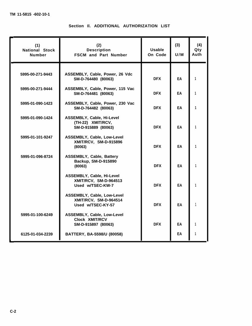
TM 11-5815 -602-10-1
Section Il. ADDITIONAL AUTHORIZATION LIST
(1) (2) (3) (4)National Stock Description Usable Qty
Number FSCM and Part Number On Code U / M Auth
5995-00-271-9443 ASSEMBLY, Cable, Power, 26 VdcSM-D-764480 (80063) DFX EA 1
5995-00-271-9444 ASSEMBLY, Cable, Power, 115 VacSM-D-764481 (80063) DFX EA 1
5995-01-090-1423 ASSEMBLY, Cable, Power, 230 VacSM-D-764482 (80063) DFX EA 1
5995-01-090-1424 ASSEMBLY, Cable, Hi-Level(TH-22) XMIT/RCV,SM-D-915889 (80063) DFX EA 1
5995-01-101-9247 ASSEMBLY, Cable, Low-LevelXMIT/RCV, SM-D-915896(80063) DFX EA 1
5995-01-096-8724 ASSEMBLY, Cable, BatteryBackup, SM-D-915890(80063) DFX EA 1
ASSEMBLY, Cable, Hi-LevelXMIT/RCV, SM-D-964513Used w/TSEC-KW-7 DFX EA 1
ASSEMBLY, Cable, Low-LevelXMIT/RCV, SM-D-964514Used w/TSEC-KY-57 DFX EA 1
5995-01-100-6249 ASSEMBLY, Cable, Low-LevelClock XMIT/RCVSM-D-915897 (80063) DFX EA 1
6125-01-034-2239 BATTERY, BA-5598/U (80058) EA 1
C-2

TM 11-5815-602-10-1
APPENDIX D
EXPENDABLE SUPPLIES AND MATERIALS LIST
Section 1. INTRODUCTION
D-1. SCOPE
This appendix lists expendable supplies and materials needed to operate and maintainthe AN/UGC-74B(V)3 or AN/UGC-74C(V]3. These items are authorized by CTA 50-970,Expendable Items (Except Medical, Class V, Repair Parts and Heraldic items).
D-2. EXPLANATION OF COLUMNS
a. Column (1) - Item Number (No.). This number is assigned to entry in the listingand is referenced in narrative instructions to identify the material (e. g., “Usecleaning compound, item 7, Appendix D. 11) .
b. Column (2) - Level. This column identifies lowest level of maintenance thatrequires listed item. (C = Operator/Crew. )
c. Column (3) - National Stock Number. This is the national stock number assigneditem; use it to request or requisition the item.
d. Column (4) - Description. Indicates Federal item name and, if required, descriptionof the item. Last line for each item indicates Federal Supply Code forManufacturer (FSCM) in parentheses, followed by part number.
e. Column (5) - Unit of Measure (U/M). Indicates measure used in performing theactual maintenance function. This measure is expressed by a two-characteralphabetical abbreviation (e. g., EA, IN, PR). If unit of measure differs from unit ofissue, requisition the lowest unit of issue that will satisfy requirements.
to
D-1

TM 11-5815-602-10-1
Section II, EXPENDABLE SUPPLIES AND MATERIALS LIST
(1) (2) (3) (4) (5)National
Item StockNumber Level Number Description U / M
1 c 7530-00-142-9037 Paper, Roll, Single Ply, White RL
2 c 7530-00-223-7966 Paper, Roll, Single Ply, Canary RL
3 c 7530-00-285-5030 Paper, Roll, 3-Piy RL
4 c 7530-00-800-0996 Paper, Fanfold, Single Ply (55295) BX
5 c Cassette, Ribbon A3041590 (80063) EA
6 c 7920-00-924-5700 Cloth, Cleaning EA
7 c 6850-00-105-3084 Trichlorotrifluoroethane, 16-oz can EA
D-2

TM 11-5815-602-10-1
APPENDIX E
AMERICAN NATIONAL STANDARD CODE FOR INFORMATION INTERCHANGE(ASCII) AND KEYBOARD TABLES
E-1. USE OF ASCII
ASCII is the standard code, using a coded character set consisting of 7-bit codedcharacters (8 bits including parity check), used for information interchange among dataprocessing systems, data communication systems, and associated equipment. The ASCIIset consists of control characters and graphic characters.
• CONTROL CHARACTER - Functional character, distinct from graphic character,which is intended to assist information exchange by controlling or modifying thefunction of machines or systems, Control characters are intended for translationby machines rather than human beings, and are normally non-printing characters
• GRAPHIC CHARACTER - Character intended to be printed or otherwise shown ina legible form.
E-2. LEGEND OF ASCII CONTROL AND GRAPHIC CHARACTERS
See paragraph E-5, ASCII Definitions, for detailed explanation of abbreviations CC,FE, and IS, use of control and graphic characters.
a, CONTROL CHARACTERS
NULSOHSTXETXEOTENQACKBEL
BSHT
LFVTFFCRs oSI
(cc)(FE)(Is)
NullStart of Heading (CC)Start of Text (CC)End of Text (CC)End of TransmissionEnquiry (CC)Acknowledge (CC)Bell (Audible or attention
signal)Backspace (FE)Horizontal Tabulation
(punched card skip) (FE)Line-Feed (FE)Vertical Tabulation (FE)Form Feed (FE)Carriage-Return (FE)Shift OutShift In
DLEDC1DC2DC3DC4NAKSYNETBCANEMSUBESCFSGSRSus
DEL
Data Link Escape (CC)Device Control 1Device Control 2Device Control 3Device Control 4 (Stop)Negative Acknowledge (CC)Synchronous Idle (CC)End of Transmission Block (CC)CancelEnd of MediumSubstituteEscapeFile Separator (IS)Group Separator (IS)Record Separator (IS)Unit Separator (IS)
Delete i
Meaning of Control Character Abbreviations
Communication ControlFormat Effecter (¹) In strict sense, DEL is notInformation Separator a control character.
E-1

TM 11-5815-602-10-1
b. GRAPHIC CHARACTERS
NAME
Space (normally non-printing)Exclamation PointQuotation MarksNumber SignDollar SignPercentAmpersandApostrophe (Closing Single Quotation Mark; Acute Accent¹)Opening ParenthesisClosing ParenthesisAsteriskPlusComma¹Hyphen (Minus)Period (Decimal Point)SlantColonSemicolonLess ThanEqualsGreater ThanQuestion MarkCommercial At2
Opening Bracket2
Reverse Slantclosing bracket² circumflex¹,²
UnderlineGrave Accent¹,²(opening single quotation mark)Opening BraceVertical LineClosing Brace2
Overline² (Tilde; General Accent¹)Diamond
¹ The symbols (II), (’), (,), (^), ('), and (~) may be used as distinguishing marks bypreceding them with an alphabetic character and BS (Backspace) in that sequence.
² These characters should not be used in international interchange withoutdetermining that there is agreement between sender and receiver.
E-2

TM 11-5815-602-10-1
E-3. ASCII DEFINITIONS
a. GENERAL.
(CC) Communication Control - Functional character intended to control or facilitatetransmission of information over communication networks.
(FE) Format Effecter - Functional character which controls layout or positioning ofinformation in printing or display devices.
(IS) Information Separator - Character which is used to separate and qualifyinformation in a logical sense. There is a group of four such characters, used inorder of precedence.
b. CONTROL CHARACTERS
NOTEOn the AN/UGC-74B(V)3 and AN/UGC-74C(V)3, the CTL (Control)key has no effect on codes generated from keys with no controlcharacter groups on the keytops. The two or three charactergroups shown on left side of keytops are control codes enteredwhen control key is operated, regardless of the position of theSHIFT key(s).
NUL (Null). Transmitted ASCII control character where all code bits are zero. One ofthe uses of NUL is to ensure acceptance and transmission of the first character ofthe message header. Header will be preceded by at least 6 NULS and 6 deletefunctions (with DEL key).
SOH (Start of Heading). Communication control character used at beginning of asequence of characters which constitute a machine-sensible address or routinginformation. Such a sequence is referred to as the "heading”. An STX character hasthe effect of terminating a heading.
STX (Start of Text). Communication control character which precedes a sequence ofcharacters that is to be treated as a complete group and transmitted through to thefinal destination. Such a sequence is referred to as “text”. STX may be used toterminate a sequence of characters started by SOH.
ETX (End of Text). Communication control character used to terminate a sequence ofcharacters started with STX and transmitted as a complete group.
EOT (End of Transmission). Communication control character, used to indicate theconclusion of a transmission, which may have contained one or more texts and anyassociated headings.
ENQ (Enquiry). Communication control character used in data communication systemsas a request for response from remote station. It may be used as "Who Are You”(WRU) to obtain identification, or may be used to obtain station status, or both.ACK (Acknowledge). Communication control character transmitted by receiver asaffirmative response to sender.
BEL (Bell). Character for use when there is need to call for human attention. It maycontrol alarm or attention devices.
E-3

TM 11-5815-602-10-1
BS (Backspace). Format effecter which controls movement of printing position oneprinting space backward on same printing line (applicable also to visual displaydevices).
LF (Line-Feed). Format effecter which controls movement of printing position to nextprinting line (applicable also to visual display devices). Where appropriate, thischaracter may have the meaning “New Line” (NL), a format effecter which controlsmovement of printing point to first printing position on next printing line. Use of thisconvention requires agreement between sender and receiver of data. (So long as thecurrent operating procedure of ending (or beginning) line with CR-CR-LF is observed,no operational problem arises from interconnecting “NL” and “Non-NL” machines.
VT (Vertical Tabulation). Format effecter which controls movement of printingposition to next in a series of predetermined printing lines (applicable also to visualdisplay devices).
FF (Form Feed). Format effecter which controls movement of printing position tofirst predetermined printing line on next form or page (applicable also to visualdisplay devices).
CR (Carriage-Return). Format effecter which controls movement of printing position tofirst printing position on same printing line (applicable also to visual display devices).
SO (Shift Out). Control character indicating that code combinations which follow shallbe interpreted as outside of the character set of standard code table until a Shift Incharacter(s) is (are) reached.
S1 (Shift In). Control character indicating that code combinations which follow shallbe interpreted according to standard code table.
DLE (Data Link Escape). Communication control character which will change meaningof a limited number of succession following characters. It is used exclusively toprovide supplementary controls in data communication networks. DLE is usuallyterminated by Shift In character(s).
DC1, DC2, DC3, DC4 (Device Controls). Characters for control of ancillary devicesassociated with data processing or telecommunication systems; more especiallyswitching devices “on” or “off”. (If a single “stop” control is required to interrupt orturn off ancillary devices, DC4 is the preferred assignment.)
NAK (Negative Acknowledge). Communication control character transmitted by receiveras negative response to sender.
SYN (Synchronous Idle). Communication control character used by synchronoustransmission system in absence of any other character to provide signal from whichsynchronism may be achieved or retained.
ETB (End of Transmission Block). Communication control character used to indicateend of block of data for communication purposes. ETB is used for blocking data whereblock structure is not necessarily related to processing format.
CAN (Cancel). Control character used to indicate that data with which it is sent is inerror or is to be disregarded.
E-4

ESC (Escape). Control character intended to provide code extention (supplementarycharacters) in general information interchange. The Escape character itself is a prefixaffecting the interpretation of a limited number of succession following characters.ESC is usually terminated by Shift In character(s).
FS (File Separator), GS (Group Separator), RS (Record Separator) and US (UnitSeparator). These information separators may be used within data in optional fashion,except that their order of precedence relationship shall be: FS is most inclusive, thenGS, then RS, and US is least inclusive. (Content and length of a File, Group, Record,or Unit are not specified.)
DEL (Delete). This character is used primarily to “erase” or “obliterate” erroneous orunwanted characters in perforated tape, (In strict sense DEL is not control character.
c. GRAPHIC CHARACTERS
SP (Space). Normally non-printing graphic character used to separate words. It is alsoa format effecter which controls movement of printing position, one printing positionforward (applicable also to visual display devices).
(Diamond). Noncoded graphic which will be printed by printing device to denotesensing of an error when such an indication is required. As an interim standard, anasterisk (*) may be used for this function.
E-4. KEYBOARD TABLES
The following three tables define received or keytop symbols and printed charactersfor Terminal Communications AN/UGC-74B(V)3 and AN/UGC-74C(V)3 in ASCII andBAUDOT modes.
● Table E-1 Keyboard - Upper Case Characters● Table E-2 Keyboard - Lower Case Characters
NOTE
Even though terminal does not have lower case letters onkeyboard, lower case letters are included in 96- and 128-symbolprinting set.
● Table E-3 Keyboard - Control Characters
NOTEIf an ASCII character with a parity error is received, a symbolwill be printed locally and the Space code will be transmitted. InBaudot local printout, when ( ) is printed, it is not put intomemory, i.e., nothing is printed during transmission.
TM 11-5815-602-10-1
EM (End of Medium). Control character associated with sent data which may be usedto identify physical end of medium, or end of the usedinformation recorded on medium. (Position of charactercorrespond to physical end of medium.)
SUB (Substitute). Character that may be substituted forto be invalid or in error.
or wanted, portion ofdoes not necessarily
character which is determined
E-5

TM 11-5815-602-10-1
Table E-1. KEYBOARD - UPPER CASE CHARACTERS
E-6

TM 11-5815-602-10-1
Table E-1. KEYBOARD - UPPER CASE CHARACTERS - Continued
PRINTED CHARACTER
ASCII BAUDOT
1
Received or Baudot 128/96 char. 64 char. Local TransmissionKeytop Symbol Symbol Print (1) Print (1) Print (2) Print
S LtrsS S S S ST LtrsT T T T TU LtrsU U U U UV LtrsV V V V VW LtrsW W W W WX LtrsX X X X XY LtrsY Y Y Y YZ LtrsZ Z Z Z Z
None • None- None { [ • None
None \ • None} None } ] • None
\ None \ \ • NoneSP(3) Ltrs/Figs SP SP SP SP SP
NOTES(1) lf an ASCll character with aparity error is received, the•
symbol is printed locally.
(2) ln Baudot local print, the Ž symbol is printed by keyboardentry only. It is not put into memory, and nothing is printedduring transmission.
(3) SP indicates a spacing action.
E-7

TM 11-5815-602-10-1
Table E-2. KEYBOARD - LOWER CASE CHARACTERS
Received orKeytop Symbol
abcdefghijkImnoPqrstuvwxY
DEL/LTRSo12345
BaudotSymbol
LtrsaLtrsbLtrscLtrsdLtrseLtrsfLtrsgLtrshLtrsiLtrsjLtrskLtrslLtrsmLtrsnLtrsoLtrspLtrsqLtrsrLtrssLtrstLtrsuLtrsvLtrswLtrsxLtrsyLtrszLtrsFigsOFigs1Figs2Figs3Figs4Figs5
PRINTED CHARACTER
ASCII
128/96 char.Print (1)
abcdefghijkImnopqr
tuvwxYz
None012345
64 char.Print (1)
ABCDEFGHIJKLMNOPQRSTUVWXYZ
None012345
BAUDOT
LocalPrint (2)
ABCDEFGHIJKLMNO
RSTUVWXYZ—012345
TransmissionPrint
ABCDEFGHIJKLMNO
RSTUVWXYZ—012345
E-8
P Q
PQ

TM 11-5815-602-10-1
Table E-2. KEYBOARD - LOWER CASE CHARACTERS - CONTINUED
NOTES
(1) If an ASCII character with a parity error is received, the •
symbol is pr inted local ly .
(2) In Baudot local print, the • symbol is printed by keyboard
entry only. It is not put into memory, and nothing is printed
during transmission.
E-9

TM 11-5815-602-10-1
Table E-3. KEYBOARD - CONTROL CHARACTERS
NOTES(1) If ASCII character with parity error is received, • symbol is locally printed. (2) In Baudot local print, • symbol is printed by keyboard entry only. It is not put
into memory, and nothing is printed during transmission.(3) Does not print or transmit horizontal tabulation code. Prints and transmits
space codes to space to tab location. (4) Returns to left margin. (5) SP indicates a spacing action.
E-10
TM 11-5815-602-10-1
APPENDIX F
OPERATOR EXAMPLES - SYSTEM COMMANDS
NOTESSee table 2-5, SYSTEM ABBREVIATIONS in Chapter 2 forexplanation of abbreviations and symbols, and table 2-6ERROR MESSAGE LIST in Chapter 2 for explanation of errormessage by number.
Symbol for System Command is
See table J-3 for shortest acceptable form for commands andsubcommands.
F-1

TM 11-5815-602-10-1
F-1. PRINT COMMAND - OPERATOR EXAMPLES
a. OPERATOR EXAMPLE NO. 1 - Single Message.
While composing message No. 8, operator sees that MESSAGE RECEIVED lamp hasturned on. Message being received is stored as message No. 9. To print outreceived message No. 9, operator uses PRINT command.
OPERATOR ACTION Inputs bOPRINTb29boCR
SYSTEM RESPONSE10 line-feedsMessage No. 9 printed out10 line-feedsPrints: CR/2LF
@CR/LF
COMMENTSystem locates and prints out message No. 9. Upon completion of printing,system returns to System Command level (message is not erased from memory)
b. OPERATOR EXAMPLE NO. 2 - Emptying Message Memory.
Operator sees that MEMORY FULL lamp has turned on and decides to emptymessage memory.
OPERATOR ACTIONInputs bOPRlNTb2*boCR
SYSTEM RESPONSE10 line-feedsHighest precedence and oldest received message printed out.10 line-feedsContinued printing of next oldest and highest precedence message until all areprinted out.Prints: CR/2LF
CR/LF
COMMENTSystem prints out messages in order, beginning with highest precedence andoldest received message. Each message is erased as it is printed. After allmessages are printed, system returns to System Command level.
F-2

TM 11-5815-602-10-1
F-2. TRANSMIT COMMAND - OPERATOR EXAMPLE
Message No. 11 has been composed and stored in message memory. Operator decides totransmit the message.
OPERATOR ACTION Inputs boTRANSMlTb211boCR
SYSTEM RESPONSE10 line-feedsPrints message10 line-feedsPrints: CR/2LF
@CR/LF
COMMENTSystem finds and prints message No. 11, marks message as transmitted, andreturns to System Command level.
F-3. REMOVE COMMAND - OPERATOR EXAMPLE
Operator decides to erase message No. 6 from message memory.
OPERATOR ACTION Inputs boREMOVEb26boCR
SYSTEM RESPONSECR/LFPrints: MESSAGE 6 REMOVED
CR/2LF
CR/LFCOMMENT
System deletes message No. 6 and returns to System Command level.
F-4. PARAMETER COMMANDS - OPERATOR EXAMPLE
See paragraph 2-14b.
F-5. EDIT COMMAND - OPERATOR EXAMPLE
See paragraph 2-14c.
F-3

TM 11-5815-602-10-1
F-6. JUSTIFY COMMAND - OPERATOR EXAMPLE
Operator has made corrections to message No. 10 and decides to justify message fornew line length.
OPERATOR ACTIONlnputs boJUSTlFYb210boCR
SYSTEM RESPONSECR/2LF@CR/LF
COMMENTSystem justifies designated message. System then returns to System Commandlevel.
F-7. QUERY COMMAND - OPERATOR EXAMPLE
Operator wants to verify status of machine using the Query command.
OPERATOR ACTIONInputs boQUERYboCR
SYSTEM RESPONSE
SOFTWARE SYSTEM CONFIGURATION = UGC-74BSWITCH STATE = KSROPERATIONAL STATE = KSRMODE = BAUDOTBAUD RATE = 1200STOP BITS = 2BELL OPTION = FIGURES JDUPLEX MODE = FULLSPACE OPTION = ONLINE LENGTH = 080LINE FEEDS = 1FONT = 1 ENG 64 CHARLINES PER PAGE = 066NUMBER OF PRINT COPIES = 1CHARACTER OR LINE TRANSMISSION ? (C/L)
COMMENTSystem executes Query command, prints message, then returns to SystemCommand level.
F-4

TM 11-5815-602-10-1
NOTESIn Baudot mode, following lines are printed:
BELL OPTION = (+ FIGURES S, FIGURES J)CR/2LF@CR/LF
In ASCII mode, following lines are printed:PARITY OPTION + ODD CAPITAL LETTER OPTION = (+ ON, OFF)CR/2LF
CR/LF
F-8. STATUS COMMAND - OPERATOR EXAMPLE
Operator wants to make sure all received messages have been printed out, and allmessages that have been composed and stored in message memory have beentransmitted. Two messages are in message memory.
OPERATOR ACTION lnputs boSTATUSb2*boCR
SYSTEM RESPONSECR/LFRECEIVED MESSAGE NO. 0001 PRECEDENCE R PRINTED 001BLOCKS CR/2LFCOMPOSED MESSAGE NO. 0002PRECEDENCE R NOT TRANSMITTED 004 BLOCKS CR/2LFMEMORY 003% FULLCR/2LF@CR/LF
COMMENTThe * input tells system to print status of all messages. System prints messagesby message number and precedence. If messages have same precedence, oldestreceived message is printed first, followed by composed message. Whethermessage is a received or composed message, and whether it has been printed ortransmitted is indicated. Total number of blocks of message memory for eachmessage used is printed, followed by total percent of message memory occupied.After completing printing, system returns to System Command level.
NOTESIf Operator has input boSTATUSb21boCR, Only information concerning message No. 1 would have been printed. Percent oftotal message memory full would also be printed.
If operator has input boSTATUSboCR, system would have printedonly the last received message and percent of message memoryall the messages occupied.
F-5

TM 11-5815-602-10-1
F-9. TTY COMMAND - OPERATOR EXAMPLE
Operator wants to notify
OPERATOR ACTIONInputs boTTYboCR
SYSTEM RESPONSECR/2LF
COMMENT
all stations that system will be off for 10 minutes.
System accepts command and issues a carriage-return and two line-feeds toindicate that is is ready for operator to enter message. Message is transmittedwhen a carriage-return is entered. System is returned to System Command level.
F-10. RESTART COMMAND - OPERATOR EXAMPLE
Due to a change in terminal use requirements, operator can restart (initialize) systemwithout turning power off. All messages in memory and parameter subcommand valuesare retained during execution of this command.
OPERATOR ACTIONInputs boRESTARTboCR
SYSTEM RESPONSEARE YOU SURE (Y/N)
OPERATOR ACTIONInputs boYboCR to continue with RESTART command.
SYSTEM RESPONSECHANGE SWITCH SETTINGS AND ENTER CR TO CONTINUE
OPERATOR ACTIONChange any system configuration control switches as required by new terminaloperation requirements, then enter CR.
SYSTEM RESPONSESystem Initialization MessagecR/2LF@CR/LF
COMMENTSystem is now in System Command level with new switch settings in effect.
F-6

TM 11-5815-602-10-1
F-II. HELP COMMAND - OPERATOR EXAMPLE
This command provides operator with a printed list of all system commands, theirformat, and a brief description of each.
OPERATOR ACTION lnputs boHELPboCR
SYSTEM RESPONSESystem prints out complete command listingCR/2LF
CR/LF
COMMENTSystem completes printing list and returns to System Command level. SeeAppendix J for complete listing of HELP messages.
MODEL C ONLY ADDITIONAL SYSTEM COMMANDS - OPERATOR EXAMPLES
NOTES
AMM - FILE NAME ASSIGNMENT DESCRIPTION
The Auxiliary Memory Module stores messages with a filingsystem that uses a DATE-TIME stamp as a file name. The formatof this naming system is shown in several System Commands inparagraphs 2-14m through 2-14s.
The AMM name assignment of DDTTTT,L obtains informationfrom formated headers on received communications or relay portmessages. DD is the day portion of DAY-MONTH-YEAR segmentof the header. TTTT is the TIME-OF-DAY (ZULU TIME) segmentof the header. L is the sequenced letter for repeated names.
If an unformatted message with no header is received, thesubstitute default name 778899,(L) is assigned during AMMstorage. (L) indicates sequence of message storage. First messagewill have a SPACE after the comma and then, as additionalmessages are stored, the character sequence of A through Z willbe used.
A default message name 778899,(L) can be changed to a morerelevant name in AMM catalog by using RENAME command.
F-7

TM 11-5815-602-10-1
F-12. GET COMMAND - OPERATOR EXAMPLE
If there is a message on the AMM that operator needs to respond to, it can be movedto message memory with this command. Operator may then edit, print, or transmit themessage.
OPERATOR ACTIONInputs boGETb2231345,b1CR
SYSTEM RESPONSEMESSAGE NUMBER 0001 IS NAMED 231345,b1CR/2LF@CR/LF
COMMENTMessage named 231345 is copied from AMM to message memory. It is numbered0001 in this example since it was the first message stored in message memory.The original message is still stored in AMM under its header oriented file nameof 231345.
See paragraph 2-14m for error message detail if command is not completed.
Message number is automatically and sequentially assigned to message when acopy transfer takes place. However, message name is not transferred with it.
F-13. NEXT COMMAND - OPERATOR EXAMPLE
If operator is not sure which message to work with next, the oldest, highestprecedence, nonaccessed messag may be accessed with this command. It will copyspecified message to message memory for editing, printing, or transmitting.
OPERATOR ACTIONlnputs boNEXTboCR
SYSTEM RESPONSEMESSAGE NUMBER 0002 IS NAMED 251030,b1CR/2LF
CR/LF
COMMENTThe message named 251030,b1 is now in message memory waiting for operatoruse. It has been assigned message No. 2 by the system according to sequence ofstored messages. If there are no unaccessed messages, message No. 42 will beprinted.
F-8

TM 11-5815-602-10-1
F-14. SAVE COMMAND - OPERATOR EXAMPLE
Having finished composing or editing a message, operator can copy message frommessage memory to the AMM. This allows for safer storage of message or forrelayingit to other terminals.
OPERATOR ACTION Inputs boSAVEb22boCR
SYSTEM RESPONSEMESSAGE NUMBER 0002 IS NAMED 778899,ACR/2LF@CR/LF
COMMENTMessageassignedmessage
No. 2 is copied to the AMM. It was received unformatted, so it wasthe default name. The A indicates that it is the second unformattedstored in the AMM. Message number is not stored with message.
F-15. CATALOG COMMAND - OPERATOR EXAMPLE
When operator needs to know what is stored in thecomplete list of message names.
OPERATOR ACTION Inputs boCATALOGboCR
SYSTEM RESPONSE
AMM, this command prints out a
System prints a listing of AMM-stored messages which includes sequence letter,priority, name, and access status.CR/LF85% AMM MEMORY AVAILABLECR/2LF
CR/LF
PRINTOUT EXAMPLE:F R 778899Z RELAY NOT ACCESSEDE R 778899Z RELAY NOT ACCESSEDD R 778899Z RELAY NOT ACCESSEDC R 778899Z RELAY NOT ACCESSEDB R 123456Z RELAY ACCESSEDA R 778899Z COMPOSED ACCESSED
R 778899Z COMPOSED ACCESSED85% AMM MEMORY AVAILABLE
COMMENTSee CATALOG command (paragraph 2-14p) for samples of printout formats.Message also indicates there is 85% AMM message storage space available.
F-9

TM 11-5815-602-10-1
F-16. CLEAR COMMAND - OPERATOR EXAMPLE
If MEMFUL indicator is ON and LS command reports that AMM is too full, operatorcan clear unneeded messages from AMM. They can be cleared one at a time, or theentire auxiliary memory can be cleared of all messages.
a. OPERATOR EXAMPLE NO. 1 - Single Message Clear.
OPERATOR ACTIONInputs boCLEARb2778899, JboCR
SYSTEM RESPONSEARE YOU SURE (Y/N)
OPERATOR ACTIONInputs boYboCR to continue CLEAR command.
SYSTEM RESPONSECR/2LF@CR/LF
COMMENTMessage maned 778899,J has been cleared from AMM memory. This can beverified with CATALOG command, whichmemory available.
b. OPERATOR EXAMPLE NO. 2 - Clear All AMM
OPERATOR ACTIONInputs boCLEARb2*boCR
SYSTEM RESPONSEARE YOU SURE (Y/N)
OPERATOR ACTIONInputs boYboCR
SYSTEM RESPONSE
******
84. AMRF******
CR/2LF@CR/LF
COMMENT
will also indicate percent of A M M
Messages.
Clearing of all AMM messages can be verified with CATALOG command, whichwould produce printed message:
43. CATALOG EMPTY100% AMM MEMORY AVAILABLE
F-10
IN PROCESS OF CLEARING ENTIRE AMM

TM 11-5815-602-10-1
F-17. RENAME COMMAND - OPERATOR EXAMPLE
AMM has stored several messages that were received unformatted so they were storedunder default name 778899,(L). Operator can rename each one with a new name suchas the date and time of accessing or handling.
OPERATOR ACTION Inputs boRENAMEb2778899, J/291530.b1CR
SYSTEM RESPONSECR/2LF
CR/LF
COMMENTWhen name change from 778899,j to 291530,bo is complete, system prints SystemCommand prompt To verify that name is changed as requested, use CATALOGcommand. See RENAME command in paragraph 2-14r for details on errormessages.
This example shows how an unformatted, default named message has been given aname related to the date and time of message handling.
F-18. CHANNEL COMMAND - OPERATOR EXAMPLE
This command allows operator to designate unit as master on relay network; cancelmaster unit designation and channel assignment; assign unit a channel number (1 to16); request channel number already assigned to unit, or reassign unit a new channelnumber.
a. OPERATOR EXAMPLE NO. 1 - Channel Assignment/Reassignment.
OPERATOR ACTION lnputs boCHANNELb25boCR
SYSTEM RESPONSE55. RELAY CHANNEL #5 REQUEST IN PROCESSCR/2LF
CR/LF** * * * *
53. RELAY CHANNEL ACTIVATED******
CR/LF
COMMENTUnit is now assigned as channel #5 on the AM/RF network. It will receive andstore AMM messages designated for channel #5 only.
F-11

TM 11-5815-602-10-1
b. OPERATOR EXAMPLE NO. 2 - Master Unit Assignment After Channel AssignmentHas Been Completed.
OPERATOR ACTIONInputs boCHANNELb2Mb0CR
SYSTEM RESPONSE79. MASTER CHANNEL SELECT ENABLEDCR/2LF@CR/LF
COMMENTMaster unit assignment request has been accepted. This means that no otherterminal on the relay network had previously been assigned as a master. Now thenetwork is enabled and message relay can take place.
c. OPERATOR EXAMPLE NO. 3 - Clear Channel Number and/or Master Assignment.
OPERATOR ACTIONInputs b0CHANNELb20bOCR
SYSTEM RESPONSE54. RELAY CHANNEL NOT ACTIVECR/2LF@CR/LF
COMMENTThe 0 parameter in CHANNEL command clears the channel number assigned. Itwill also clear a master unit assignment if one has been previously performed. Ifthe master unit assignment is cleared, the relay network is disabled until one ofthe terminals on the system is assigned as a master.
F-19. RELAY COMMAND - OPERATOR EXAMPLE
NOTEBefore RELAY command may be performed, Master channel mustbe designated on relay network.
Operator has message that has been composed and stored in AMM, and now needs tobe relayed to other stations on relay network. Using RELAY command allows operatorto send message to one or more stations at the same time.
a. OPERATOR EXAMPLE NO. 1 - Relay to One Network Terminal.
OPERATOR ACTIONInputs boRELAYb2778899, C/2b2CR
F-12

TM 11-5815-602-10-1
SYSTEM RESPONSE58. RELAY MESSAGE #1 PREPAREDCR/2LF@CR/LFTerminal waits for Master terminal permission to output message onto relaynetwork, then prints:32. RELAY MESSAGE #1 IN PROGRESSCR/LF******
51. COMPLETED RELAY MESSAGE #1******
CR/LF
COMMENTMessage named 778899,C has been relayed to assigned channel No. 2. It was thefirst message relayed since system was initialized on power-up. This is indicatedby the #1 in messages No. 58 and No. 32. Messages relayed count will step up byone each time another message is relayed. Counter can only be reset by a power-down, then power-up reinitialization process.
b, OPERATOR EXAMPLE NO. 2 - Multi-terminal Relay.
OPERATOR ACTIONInputs boRELAYb2251300,b1/1,2,5,11b2CR
SYSTEM RESPONSE58. RELAY MESSAGE #2 PREPAREDCR/2LF@CR/LF46. RELAY MESSAGE #2 IN PROGRESSCR/LF******
44. CANNOT RELAY TO CHANNEL #551. COMPLETED RELAY MESSAGE #2******
CR/LF
COMMENTMessage named 251300, the second one relayed, was relayed to and accepted byAM/RF channels #1, #2, and #11. Channel #5 did not receive and store themessage. This may have been caused by one of several equipment reasons at theterminal that should have been assigned channel #5. See CHANNEL commandparagraph 2-14t and RELAY command paragraph 2-14s.
F-13

TM 11-5815-602-10-1
F-20. TST COMMAND - OPERATOR EXAMPLE
Operator wants to check AM/RF subsystem operating condition to verify correctoperation. This is done with the TST command.
OPERATOR ACTIONInputs boTSTboCR
SYSTEM RESPONSESystem respondsC R / 2 L F
XXX% AMMCR/LF
COMMENTSystem has
in approximately 10 seconds
MEMORY AVAILABLE
completed AM/RF self-test and has found no failure in the subsystemIf one had been found, one of the following error or status messages would havebeen printed depending on system condition:
*59. TEST NOT ALLOWED; MESSAGE RELAY IN PROGRESS60. MAINTENANCE NOTE: ROM TEST FAlLED (A2A4)61. MAINTENANCE NOTE: RAM TEST FAlLED (A2A4)62. MAINTENANCE NOTE: SCC/RELAY TEST FAlLED (A2A4)63. MAINTENANCE NOTE: RTC TEST FAILED (A2A4)
*64. COMMAND NOT ACCEPTED, AUX MEMORY OR RELAY BUSY*65. AUX MEMORY AND RELAY FUNCTION NOT OPERATING69. A1A2 FAILURE
NOTE* Denotes system status messages due to operating conditions.
F-21. CANCEL COMMAND - OPERATOR EXAMPLE
Operator has started to relay a message and then decides to do additional editing andchange the content. The relay function may be terminated with CANCEL command.
OPERATOR ACTIONInputs boCANCELboCR
SYSTEM RESPONSE 46. RELAY MESSAGE #3 CANCELED IN PROGRESSCR/2LF@CR/LF** * * * *
91. RELAY MESSAGE #3 NOT SAVED BY CH #7** * * * *
CR/LF
F-14

TM 11-5815-602-10-1
COMMENTThe third message to be relayed that was on its way to channel #7 was canceledin progress. This is indicated by messages No. 46 and No. 91. The station(channel #7) that did not receive the complete message (third message) wouldprint message No. 35 RELAY MESSAGE #3 FROM CH #1 NOT SAVED.
F-22. 1S COMMAND - OPERATOR EXAMPLE
Operator has observed that MEMFUL and MSG RCVD lamps are on. Reasons forindications may be determined with the LS command.
OPERATOR ACTIONInputs boLSboCR
SYSTEM RESPONSEPrints MEMFUL lamp messages:MEMORY 95% FULL65% AMM MEMORY AVAILABLE
Prints MSG RCVD lamp messages:NO LOW PRECEDENCE NONPRINTED MESSAGES IN MESSAGE MEMORYNO HIGH PRECEDENCE NONPRINTED MESSAGES IN MESSAGE MEMORY
LOW PRECEDENCE NONACCESSED MESSAGES ON THE AMMNO LOW PRECEDENCE NONACCESSED MESSAGES ON THE AMM
COMMENTMessage responses to the LS command have shown that the message memory isnearly full and some messages should be removed. Also, there is an unaccessedmessage on the AMM. This is shown by removal of the (NO) in front of theappropriate message category.
F-15

TM 11-5815-602-10-1
APPENDIX G
OPERATOR EXAMPLES - PARAMETER SUBCOMMANDS
NOTESSee table 2-5 SYSTEM ABBREVIATIONS in Chapter 2 forexplanation of abbreviations and symbols, and to table 2-6ERROR MESSAGE LIST in Chapter 2 for explanation of errormessages by number.
Printed symbol for PARAMETER command is a dash (–)
G-1. LINE SUBCOMMAND
This subcommand allows operator to select length of the text line. On power-upinitialization, the line length is set at 80. If no value is selected, 80 is used. Valueselected must be between 40 and 132, or error message No. 22 (INPUT IGNORED,LINE LENGTH UNACCEPTABLE) is printed and the subcommand is terminated.
a. Keystroke sequence for LINE subcommand is either:(1) boLlNE(+b2XXX)boCR (XXX represents line length figure.)(2) boLINEboCR (If no value is input, system recognizes value as 80.)
b. Shortest acceptable form of subcommand is LIN.
c. OPERATOR EXAMPLE: Having entered PARAMETER command level in paragraph2-14b, operator decides to set text line length at 60. Operator knows from theprompt sequence printout (CR/2LF – CR/LF) that the system is ready to acceptLINE subcommand as follows:
OPERATOR ACTIONlnputs boLlNEb260boCR
SYSTEM RESPONSECR/2LF
CR/LF
COMMENTTerminal accepts input and sets line length at 60.
G-2. SETAB SUBCOMMAND
This subcommand allows operator to select one or more tab positions. If any of theselected tab sets exceed the set line length, error message No. 10 (INVALID ORMISSING COMMAND VARIABLE) is printed, and only valid tabs are set. If a selectedtab is already set, no change is made. No more than 12 tabs can be set. Total numberof tabs includes previously selected and new tab settings.
G-1

TM 11-5815-602-10-1
a.
b.
c.
d.
e.
If more than 12 tabs are selected, subcommand accepts the first 12 tabs and printserror message No. 9 (USE 12 TABS MAXIMUM). System returns to PARAMETERcommand level, and PARAMETER command prompt sequence symbol is printed.
After accepting and setting position, systempositions.
Keystroke sequence for SETAB subcommandposition) boCR.
Shortest acceptable form of subcommand is
prints all previously set and new tab
is boSETAB#b2 (enter desired tab set
SETA.
OPERATOR EXAMPLE: Remaining in PARAMETER subcommand level, operatordecides to set tabs at 40, 45, and 60
OPERATOR ACTIONInputs boSETABb240b245b260boCR
SYSTEM RESPONSECR/LF040b1b1045b1b1060CR/2LF—CR/LF
COMMENTTerminal accepts input and sets tabs at 40, 45, and 60. It issues PARAMETERprompt sequence.
G-2. CLRTAB SUBCOMMAND
This subcommand allows operator to clear one to 12 specified tabs. To remove all tabsset, enter "*”. System is powered up with no tabs set.
a.
b.
c.
d.
After clearing specified tabs, any remaining tabs are printed. If no tabs remain,error message No. 20 (NO TABS SET) prints.
Keystroke sequence for CLRTAB subcommand is boCLRTAB(+(#b2XX), b2*)boCR.
Shortest acceptable form of subcommand is CLR.
OPERATOR EXAMPLE: Still operating in PARAMETER subcommand level, operatorwants to clear tab set at 45.
OPERATOR ACTIONlnputs boCLRTABb245boCR
G-2

TM 11-5815-602-10-1
SYSTEM RESPONSECR/LF040b1b1060CR/2LF
CR/LF
COMMENTTerminal accepts command, clears tab at 45, and responds by printing tabs set interminal, followed by PARAMETER prompt sequence.
G-4. DISPLAY SUBCOMMAND
This subcommand allows operator to print out all tab settings, in order from lowest tohighest. If none are set,
a.
b.
c.
d.
Keystroke sequence
Shortest acceptable
System response is
error message No. 20 (NO TABS SET) is printed.
for DISPLAY subcommand is boDISPLAYboCR.
form of subcommand is D1.
XXX(#b1b1XXX). (XXX represents tab setting.)
OPERATOR EXAMPLE: With tab system operating in PARAMETER subcommandlevel, operator wants to check tab settings.
OPERATOR ACTIONInputs boDISPLAYboCR
SYSTEM RESPONSECR/LF000b1b1060CR/2LF
CR/LF
COMMENTTerminal prints tab settings and issues PARAMETER prompt sequence.
G-5. CAPIT SUBCOMMAND
NOTEThis subcommand is only available in the ASCII mode.
This subcommand allows operator to set or reset capitalize option. If this option isset, all lower case letters (a through z) input from the keyboard are changed tocapitals and stored as such in memory. If this option is not set, no change is made.
G-3

TM 11-5815-602-10-1
a.
b.
c.
d.
If CAPIT option is tried in Baudot mode, error message No. 125 (COMMANDINVALID FOR BAUDOT) is printed.
Keystroke sequence for CAPIT subcommand is b0CAPITb2(+ON,OFF) b0CR.
Shortest acceptable form of subcommand is CAP.
OPERATOR EXAMPLE: With system in PARAMETER subcommand level, operatorwants to set CAPIT option to OFF.
OPERATOR ACTIONInputs b0CAPITb2OFFb0CR
SYSTEM RESPONSECR/2LF—CR/LF
COMMENTTerminal accepts command and all letters are stored in message memory withoutbeing changed.
G-6. REMIND SUBCOMMAND
This subcommand allows operator to have REMIND option on or off. If REMIND optionis on, whenever a TRANSMIT command or a TTY command is given in the ICT state,the following reminder is printed: KEY TRANSMITTER AND ENTER CR CR/2LF.
NOTEKEY TRANSMITTER refers to turning TRANSFER switch to ON.
a. On power-up initialization, this option is off.
b. Keystroke sequence for REMIND subcommand is b0REMINDb2(+ON, OFF) b0CR.
c. Shortest acceptable form of subcommand is REMI.
d. OPERATOR EXAMPLE: With system in PARAMETER subcommand level, operatorwants to have the REMIND option on.
OPERATOR ACTIONInputs b0REMINDb2ONb0CR
SYSTEM RESPONSECR/2LF
CR/LF
COMMENTTerminal accepts command and sets REMIND option for TRANSMIT and/or TTYcommands.
G-4

TM 11-5815-602-10-1
G-7. END-OF-LINE SUBCOMMAND
This subcommand allows operator to select the end-of-line (EOL) sequence fortransmission. The EOL character is sent in place of a carriage-return.
a.
b.
c.
d.
e.
f.
g.
NOTEWhen transmission circuit requirements dictate a change in EOL,the station SOP determines the change.
EOL character sequence consists of zero to eight characters.
If more than eight characters are selected, error message No. 10 (INVALID ORMISSING COMMAND VARIABLE) is printed.
On power-up initialization, EOL sequence is: Characters: CR CR LF.
If transmission is in process when EOL subcommand is selected, error message No.19 (COMMAND NOT ACCEPTED, MESSAGE IS CURRENTLY IN TRANSMISSION ONCOMM PORT) is printed, no change is made, and subcommand is complete.
Keystroke sequence for EOL subcommand is b0EOL(#b2A)boCR.
Shortest acceptable form of subcommand is EOL.
OPERATOR EXAMPLE: While in PARAMETER subcommand level, operator decidesto attach ASCII character - to the end of each line.
OPERATOR ACTIONinputs bOEOLb2-bOCR
SYSTEM RESPONSECR/2LF
CR/LF
G-8. LINE-FEED SUBCOMMAND
This subcommand allows operator to select either one or two line-feeds following acarriage-return.
a. On power-up initialization, line-feed is set at 1.
b. Keystroke sequence for LINE-FEED subcommand is boLFb2(+l,2)boCR.
c. If 1 or 2 is not specified, error message No. 10 (INVALID OR MISSING COMMANDVARIABLE) is printed.
d. Shortest acceptable form of subcommand is LF.
G-5

TM 11-5815-602-10-1
e.
G-9.
In
a.
b.
c.
d.
e.
f.
g.
OPERATOR EXAMPLE: In PARAMETERline-feed after each carriage-return.
OPERATOR ACTION lnputs b0LFb2(+l,2)b0CR
SYSTEM RESPONSE CR/2LF—CR/LF
COMMENT
subcommand level, operator wants a double
Terminal accepts input and sets a double line-feed into the system
SPACE SUBCOMMAND
ASCII only, this subcommand allows operator to have space option on or off.
If space option is on and a tab character is input, tab character is replaced by aspace. Spaces are inserted until a tab position or the end of the line is reached.
If spaceinserted
In ASCII,
option is off, tab character is inserted into the message. Spaces areuntil a tab set position or the end of the line is reached.
NOTEIf ON or OFF is not inserted as an operand, error messageNo. 10 (INVALID OR MISSING COMMAND VARIABLE) is printed,and no change is made.
space option is off at power-up initialization, but may be placed in anO N p o s i t i o n .
In Baudot, space option is on at power-up initialization, but cannot be placed inOFF position.
Keystroke sequence for SPACE subcommand is b0SPACEb2(+ON,OFF)boCR.
Shortest acceptable form of subcommand is SP.
OPERATOR EXAMPLE: System is in ASCII mode and operator wants to activatespace option to ON.
OPERATOR ACTIONInputs b0SPb20Nb0CR
SYSTEM RESPONSECR/2LF
CR/LF
COMMENTTerminal accepts input and sets SPACE option.
an
G-6

TM 11-5815-602-10-1
G-10. PAPER SUBCOMMAND
This subcommand turns off the printer so that paper and/or ribbon may be changedwithout a loss of messages in memory. No further inputs are printed until printer isrestarted by executing GO subcommand. All other keystrokes are ignored.
NOTEPAPER subcommand is only valid in ICT state.
a. LINE-FEED switch is activated to assist in loading paper.
b. Incoming messages are lost if memory becomes full while printer is inactive.
c. If paper runsfeed.
out, PAPER subcommand is activated and stops printer and ribbon
NOTEOperator must initiate GO command to enable printer.
d. Keystroke sequence for PAPER subcommand is b0PAPERb0CR.
e. Shortest acceptable form of subcommand is PAP.
f. OPERATOR EXAMPLE: While in PARAMETER subcommand level, operator wants toresupply terminal with
OPERATOR ACTIONInputs b0PAPERb0CR
SYSTEM RESPONSE
paper.
Printer and ribbon feed stop.
COMMENTPaper and/or ribbon may be changed. All keystrokes are ignored until GO CR isentered.
G-11. GO SUBCOMMAND
This subcommand restarts the motor that operates printer and ribbon feed.
a. Keystroke sequence for the GO subcommand is GO CR.
b. Shortest acceptable form of subcommand is GO.
c. OPERATOR EXAMPLE: While in PAPER subcommand, operator replenishes papersupply or ribbon. When operator is ready to turn on printer and ribbon feed,operator performs the following:
OPERATOR ACTIONInputs boGOboCR
G-7

TM 11-5815-602-10-1
SYSTEM RESPONSECR/2LF—CR/LF
COMMENTTerminal accepts command. Printer and ribbon feed start operating again.Terminal is returned to PARAMETER command level
NOTEIf system has been in SYSTEMS command, or EDIT command, andpaper has run out, system would have automatically returned tothat command level.
G-12. TENVELOPE SUBCOMMAND
This subcommand allows operator to set the envelope which is put around a messagefor transmission. This sequence never appears in the message storage and is used forcommunications purposes only.
a.
b.
c.
d.
e.
NOTEStation SOP will determine the characters for TRANSMITENVELOPE option.
Envelope consists of zero to eight characters of start sequence.
If more than the required characters are specified, error messageOR MISSING COMMAND VARIABLE) is printed.
No. 10 (INVALID
If a message is being transmitted when TENVELOPE subcommand is selected, errormessage No. 19 (COMMAND NOT ACCEPTED, MESSAGE IS CURRENTLY INTRANSMISSION ON COMM PORT) is printed. No change is made, and subcommandis
In
In
complete.
Baudot mode, on power-up initialization, envelope is empty.
ASCII mode, on power-up initialization, envelope is as follows:
ASCII CHARACTERS
Front: V Z C Z C :End: N N N NRepeated 12 times: D E
f. Keystroke for TENVELOPE subcommand is b0TENVELOPE(#b2A):(#b2A)bOCR.
NOTEIf null (no) envelopes are desired, do not enter any charactersafter the space following the subcommands. Enter the colon (:), aspace, and a CR.
G-8

TM 11-5815-602-10-1
g. Shortest acceptable form of subcommand is TENV.
h. OPERATOR EXAMPLE: While in PARAMETER subcommand level, operator decidesto change TENVELOPE using characters to read BEGIN and END.
OPERATOR ACTIONInputs b0TENVELPOEb2Bb2b2Gb2Ib2N:b2Eb2Nb2Db0CR
SYSTEM RESPONSECR/2LF
CR/LF
COMMENTThis establishes transmit envelope as:
ASCII CHARACTERSFront: BEGINEnd: END
G-13. RENVELOPE SUBCOMMAND
This subcommand allows operator to set envelope which is removed from a message onreception. This sequence never appears in message storage and is used forcommunication purposes only.
a. Envelope consists of zero to eight characters of start sequence, and zero tosixteen characters of stop sequence. These sequences are entered as ASCIIcharacters.
b. If more than the required characters are specified, error message No. 10 (INVALIDOR MISSING COMMAND VARIABLE) is printed.
c. If a message is being received when the RENVELOPE subcommand is selected,error message No. 19 (COMMAND NOT ACCEPTED, MESSAGE IS CURRENTLY INTRANSMISSION ON COMM PORT) is printed, no change is made, and subcommandis
d. In
e. In
complete.
Baudot mode, on power-up initialization, the envelope is empty.
ASCII mode, on power-up initialization, the envelope is as follows:
ASCII CHARACTERSFront: V C Z CEnd: N N N N
f. Keystroke sequence
g Shortest acceptable
for RENVELOPE subcommand is
form of subcommand is RENV.
b0RENVELOPE(#b2A) :(#b2A)b0CR.
G-9

TM 11-5815-602-10-1
h. OPERATOR EXAMPLE: While in PARAMETER subcommand level, operator decides tochange RENVELOPE using characters to read BEGIN and END.
OPERATOR ACTIONInputs b0RENVELOPEb2Bb2b2Gb2lb2N:b2Eb2Nb2Db0CR
SYSTEM RESPONSECR/2LF
CR/LF
COMMENTThis establishes receive envelope as:
ASCII CHARACTERSFront: BEGINEnd: END
G-14. EOMLF SUBCOMMAND
This subcommand allows operator to set number of line-feeds which are automaticallyinserted following message printout. Value specified must be betweenor error message No. 10 (INVALID OR MISSING COMMAND VARIABLE) isno change is made.
a. On power-up initialization, EOMLF is set to 20.
b. Keystroke sequence for EOMLF subcommand is b0EOMLFb2(XX)boCR,
c. Shortest acceptable form of subcommand is EOM.
1 and 20 inclusiveprinted, and
d. OPERATOR EXAMPLE: While in PARAMETER subcommand level, operator decides tochange number of line-feeds following message printout.
OPERATOR ACTIONInputs b0EOMLFb25boCR
SYSTEM RESPONSEEOMLF 5CR/2LF
CR/LF
COMMENTSystem will now automatically perform five line-feeds after each message printout
G-10

TM 11-5815-602-10-1
G-15. FONT SUBCOMMAND
This subcommand allows operator to specify the character set used by the printer. Valuespecified must be between 1 and 6 inclusive or error message No. 10 (INVALID ORMISSING COMMAND VARIABLE) is printed, and no change is made. On power-upinitialization, font selected is 1 and is the 64 character ASCII set. Font 2 is the 96character ASCII set, and font 3 is the 128 character ASCII set. Fonts 4, 5, and 6 arenot yet available. If they are selected, error message No. 29 (FONT NOT AVAILABLE) isprinted.
a. Keystroke sequence for FONT subcommand is boFONTb2(X)b0CR.
b. Shortest acceptable form of subcommand is FO.
c. OPERATOR EXAMPLE: While in PARAMETER subcommand level, operator decides tochange the ASCII set for printing. Font 2 is selected so that messages may beprinted in upper case and lower case.
OPERATOR ACTIONlnputs bOFONTb22b0CR
SYSTEM RESPONSEFONT 2CR/2LF—CR/LF
COMMENTSystem will now print messages using full upper and lower case characters.
G-16. COPIES SUBCOMMAND
This subcommand allows operator to specify the number of copies in the multipart paperbeing used. Value specified by operator must be between 1 and 3 inclusive or errormessage No. 10 (INVALID OR MISSING COMMAND VARIABLE) is printed, and no changeis made. On power-up initialization, the number of copies is set to 1.
a. Keystroke sequence for COPIES subcommand is b0COPlESb2(X)b0CR.
b. Shortest acceptable form of subcommand is CO.
c. OPERATOR EXAMPLE: Operator has changedprinter. This change of paper thickness cansubcommand.
OPERATOR ACTIONInputs b0COPlESb23 b0CR.
paper to three-part (copy) in thebe adjusted for with the COPIES
G-11

TM 11-5815-602-10-1
SYSTEM RESPONSECOPIES 3CR/2LF—CR/LF
COMMENTThe print head pressure during printing is adjusted.
G-17. DUPLEX SUBCOMMAND
This subcommand allows operator to set the mode of operation for communications lineto helf-duplex or full-duplex. When in full-duplex, messages can be received andtransmitted on the communications line simultaneously. When in half-duplex, thecommunications line can either receive or transmit messages, but not at the same time.
If “F” or "H” is not inserted in the parameter field, error message No. 10 (INVALID ORMISSING COMMAND VARIABLE) is printed, and no change is made. On power-upinitialization, DUPLEX option is set to FULL. If a message is currently beingtransmitted and/or received when DUPLEX subcommand is recognized by system, errormessage No. 11 (COMMAND NOT ACCEPTED, COMMUNICATIONS PORT BUSY) isprinted, and no change is made.
a. Keystroke sequence for DUPLEX subcommand is boDUPLEXb2(H,F) boCR.
b. Shortest acceptable form of subcommand is DU
c. OPERATOR EXAMPLE: While in PARAMETER subcommand level, operator needs tochange operating mode to half-duplex. This is used to stop remote station fromechoing back the message.
OPERATOR ACTIONInputs boDUPLEXb2HboCR
SYSTEM RESPONSEDUPLEX HCR/2LF—CR/LF
COMMENTSystem is now in half-duplex mode on the communications port.
G-18. HEADERS SUBCOMMAND
This subcommand allows operator to print current header information for theJANAP-128, ACP-127 NATO Supp 3, and ACP-127 USA Supp 1 headers. For each headertype, the type and the current header is printed. If the header has not been created,error message No. 23 (NO HEADER DEFINED) is printed.
G-12

TM 11-5815-602-10-1
a. Keystroke sequence for HEADERS subcommand is boHEADERSboCR.
b. Shortest acceptable form of command is HEADERS.
c. OPERATOR EXAMPLE: Operator needs to determine which headers have been set up.
OPERATOR ACTIONInputs boHEADERSboCR
SYSTEM RESPONSEHEADERSCR/LFJANAP 128CR/2LF(Prints JANAP 128 header information as defined with SETUP subcommand.)CR/LFACP-127CR/2LF23. NO HCR/2LFACP-127CR/2LF
USA SUPP 1
EADER DEFINED
NATO SUPP 3
23. NO HEADER DEFINEDCR/2LF
CR/LF
COMMENTHeader setup under the JANAP 128 format had been previously defined so itprinted out with appropriate information. The other two formats for headers werenot set up, so message No. 23 (NO HEADER DEFINED) printed out, indicating nosetup for each one.
G-19. SETUP SUBCOMMAND
This subcommand provides prompting for aSupplement 1, or ACP-127 NATO Supplement
JANAP 128 PLAINDRESS, ACP-127 USA3 header format. The current line length
must be set at 69 characters or less for this subcommand. If the current line length isgreater than 69, error message No. 6 (COMMAND NOT ACCEPTED, CURRENT LINE TOOLONG, CHANGE LINE PARAMETER) is printed and the subcommand is terminated.Prompting consists of the machine automatically printing a series of questions, each onefollowed by a carriage-return, line-feed, and the present value of the item beingrequested. After each question, operator must respond with a typed input, followed by acarriage-return, or just a carriage-return. The number and type of characters to beinput are given in parentheses at the end of each question. If the input does notconform in number or type, error message No. 10 (INVALID OR MISSING COMMANDVARIABLE) is printed and the question is repeated.
G-13

TM 11-5815-602-10-1
Whenever data is being inputted, leading and trailing spaces are allowed. Correctionkeys (DLC, DLL, REV) and CAPIT command are active. All numbers are entered with orwithout leading zeros as required. If HLT key is activated during prompting, promptingsequence is terminated and control is returned to the PARAMETER subcommand level.For purposes of constructing the header, the answer to each question is considered as avariable which carries the same number as the question (e.g., question 1 - channelidentifier is V1).
The variables and their corresponding number and kind of value are as follows: (Notethat line one above corresponds to variable one (V1), line two to variable two (V2)}
etc.)
V1V2V3
V4V5
V6V7V8V9V10V11V12
ŽŽ
ŽŽ
ŽŽŽŽŽ
ŽV13A-V14 -V15 -V16 -V17 -
3 alphaR1/PLA1 alpha must be: Y - emergency
Z - flashO - immediateP - priorityR - routine
2 alpha1 alpha must be: U - unclas
E - unclas EFTOC - confidentialS - secretT - top secretR - Restricted
4 alpha/numeric4 numeric3 numeric4 numericRI/PLA (may have multiple inputs)RI/PLA (may have multiple inputs)4 numeric2 numeric V13B - 3 alpha3 numericRI/PLA (may have multiple inputs)2 alpha1 alpha
V13C - 2 numeric
The Routing Indicator/Plain Language Address (RI/PLA) is entered asbORIb0/bOPLAbOCR.
RI is four to seven alpha characters, and PLA is any amount of text necessary. Eachline of PLA text must be terminated by an operator-entered carriage-return. If a line ofPLA text exceeds the current line length (69 characters or less), message No. 22 (INPUTIGNORED, LINE LENGTH UNACCEPTABLE) is printed, the R1/PLA is not saved, andquestion No. 2 is repeated. The PLA text, and thus question No. 2, is terminated byentering a null line (boCR).
NOTEA total of 8 lines of RI/PLA may be entered. This includesORIGINATOR, ACTION, INFO, and EXEMPT addresses.
G-14

TM 11-5815-602-10-1
a. Keystroke sequence for SETUP subcommand is b0SETUPb2(128,1271,1273 )b0CR.
b. Shortest acceptable form of subcommand is SETU.
c. OPERATOR EXAMPLE: Operator needs to set up a formatted message using JANAP128 format.
OPERATOR ACTIONInputs b0SETUPb2128b0CR
SYSTEM RESPONSESystem prints out a series of prompting questions that operator must answer orrespond to with at least a CR.
Text of each of the questions (for all three header formats) is as follows:
1.2.3.4.5.6.7.8.9.10.11.12.13.14.
ENTER CHANNEL IDENTIFIER (3A)ENTER ORIGINATOR ROUTING INDICATOR/PLAIN LANGUAGE ADDRESS (Rl/PLA)ENTER MESSAGE PRECEDENCE (1A)ENTER ORIGINATOR AND DESTINATION LANGUAGE AND MEDIA FORMAT (2A)ENTER CLASSIFICATION (1A)ENTER CONTENT INDICATOR/COMMUNICATION ACTION IDENTIFIER (4AN)ENTER STATION SERIAL NUMBER (4N)ENTER JULIAN DATE (3N)ENTER TIME FILED (4N)ENTER ACTION ROUTING INDICATOR/PLAIN LANGUAGE ADDRESS (Rl/PLA)ENTER INFORMATION ROUTING INDICATOR/PLAIN LANGUAGE ADDRESS (Rl/PLA)ENTER TIME OF DAY (ZULU TIME) (4N)ENTER DAY, MONTH, AND YEAR (2N 3A 2N)ENTER CHANNEL SEQUENCE NUMBER (3N)
NOTEFor ACP-127 formats, the following additional questions are asked:
15. ENTER EXEMPT ROUTING INDICATOR/PLAIN LANGUAGE ADDRESS (Rl/PLA)16. ENTER SECURITY PROSIGN (+2 A, NULL)
Two prosigns are recognized - UU and HH. A null input will be accepted, inwhich case no security prosign will be included in format line 1.
17. ENTER SECOND PRECEDENCE (+1A,NULL)
COMMENTFor the JANAP 128 format questions, when the first 14 are complete, theformatting is finished. This may be verified using HEADERS subcommand. SystemIS now in PARAMETER (–) command level.
If either of the ACP-127 formats had been designated in the subcommand, thethree additional questions would have been prompted by the system.
G-15

TM 11-5815-602-10-1
d. The JANAP 128 PLAINDRESS header and trailer are formed as follows:Header is formed as follows and inserted before body of message.(1) VI V14 CR(2) V3 V4 V5 V6 (Rl from V2) V7 V8 V9 - (repeat V5 four times) - (Rls from
V10 and V11 separated by spaces or CR as required) CR(3) ZN (if V5 = U then R else Y) (repeat V5 five times) CR(4) V3 V13A V12 Z V13B V13C CR(5) FM V2 (PLA only) CR(6) TO (V10 each entry shall be separated by CR) CR(7) INFO (V11 each entry shall be separated by CR) CR(8) BT CR(9) Based on V5, classification is entered here and written out as follows:
U - UNCLASE - UNCLASS E F T OC - c o n f i d e n t i a lS - SECRETT - TOP SECRET CR
Trailer of message is as follows and appended after body of message.BT CR# V7 CR LF LF LF LF LF LF LF
The ACP-127 NATO Supplement 3 PLAINDRESS header is formed as follows andinserted before body of message:
(1) V1V14 V16 CR(2) V3 (repeated twice) V10A V11A CR(3) DE V2 (Rl only) V7 V8V9 CR(4) ZN (if V5 = U then R else Y) V5 (repeated five times) CR(5) V3 V13AV12Z V13B V13C CR
or, (if V17 is not null)V3 V17 V13AV12Z V13B V13C CR
(6) FM V2 CR(7) TO V10 CR(8) INFO V11 CR(9) XMT V15 CR(10) BT CR(11) Based on V5, classification is entered here and written out as follows:
NATO UNCLAS N A T O R E S T R I C T E DN A T O CONFIDE N T I A LN A T O S E C R E TN A T O T O P S E C R E T CR
The ACP-127 USA Supplement 1 PLAINDRESS header is formed the same asACP-127 NATO Supplement 3 except for format line 3 and the security words initem 11 (format line 12), A number sign will be placed before V7 in format line 3and the security words inserted will be the same as those inserted for theJANAP 128 header.
If the system is operating in Baudot mode, header and trailer are formed as aboveand inserted before the body of message. LTRS and FIGS codes are inserted intothe message as required for transmission only. In both ASCII and Baudot, end ofline sequence (EOL) is substituted for CR as the message is transmitted.
G-16

TM 11-5815-602-10-1
G-20. PAGE SUBCOMMAND
This subcommand allows operator to select the number of lines to be printed prior tothe automatic insertion of enough line-feeds to form a page which is 66 lines inlength. Value specified must be between 1 and 66 inclusive or error message No. 10(INVALID OR MISSING COMMAND VARIABLE) is printed and subcommand terminates.To turn off auto line-feed insertion, operator enters 66. On power-up initialization,PAGE length is set to 66 lines.
a. Keystroke sequence for PAGE subcommand is b0PAGE b2(XX)b0CR.
b. Shortest acceptable form of subcommand is PAG.
c. OPERATOR EXAMPLE: Operator has a 150-line message to print on fanfold 66-linepaper. To cause printer to fill in enough line-feeds to produce the 66-line pages,PAGE subcommand is used.
OPERATOR ACTIONInputs b0PAGEb255b0CR
SYSTEM RESPONSEPAGE 55CR/LFALIGN PAPER AND ENTER CR TO CONTINUEcR/2LF—CR/LF
COMMENTSystem will print 55 lines of text per page, perform 11 line-feeds, and print therest of the message in this manner. This is used primarily with 11-inch standardform feed paper to prevent printing over page perforations.
G-21. HELP SUBCOMMAND
This subcommand allows operator to print aincludes the subcommand format and a brief
list of PARAMETER subcommands. Listdescription of subcommand function.
a. Keystroke sequence for HELP subcommand is b0HELPb0CR.
b. Shortest acceptable form of subcommand is HEL.
c. OPERATOR EXAMPLE: Operator requires assistance in remembering a seldom usedPARAMETER subcommand. HELP subcommand obtains a list of all PARAMETERsubcommands.
OPERATOR ACTIONlnputs b0HELPb0CR
G-17

TM 11-5815-602-10-1
SYSTEM RESPONSESystem prints list of PARAMETER subcommands.
COMMENTList will contain shortest acceptable form and a brief description of allPARAMETER subcommands.
See Appendix J for complete listing of PARAMETER subcommands
MODEL C ONLY ADDITIONAL PARAMETER SUBCOMMANDS.
G-22. AUTOS SUBCOMMAND
This subcommand allows operator to set or reset AUTO SAVE message option. If thisoption is ON, all received messages through communications port will be stored inmessage memory and also stored in auxiliary memory. If OFF, received messages willbe stored in message memory only.
If "ON" or "OFF" is not inserted in parameter field, error message No. 10 (INVALIDOR MISSING COMMAND VARIABLE) is printed, and no change is made. On power-upinitialization, AUTOS option is ON. If system configuration is not UGC-74C(V)3 andthis subcommand is entered, error message No. 65 (AUX MEMORY AND RELAYFUNCTION NOT OPERATING) is printed and subcommand is complete.
a. Keystroke sequence for AUTOS subcommand is b0AUTOSb2(+ON,OFF) b0CR.
b. Shortest acceptable form of command is AUTOS.
c. OPERATOR EXAMPLE: Operator wants to ensure that incoming messages do notget lost if there is a power failure. Communications port messages can beautomatically saved to auxiliary memory with AUTOS subcommand.
OPERATOR ACTIONInputs b0AUTOSb2ONb0CR
SYSTEM RESPONSEAUTOS ONCRJ2LF—CR/LF
COMMENTSystem has accepted automatic save on subcommand and returned to PARAMETERsubcommand level.
G-18

TM 11-5815-602-10-1
G-23. AUTOP SUBCOMMAND
This subcommand allows operator to set or resetoption is used in conjunction with AUTOS option,message after a 60-second delay. If AUTOS option
AUTO PRINT message option. Thisand will automatically print relayis OFF, error message No. 31
(COMM -AND NOT ACCEPTED, AUTOSAVE MUST BE ON) is printed and subcommandterminates. If AUTOS option is ON and AUTOP option is also ON, messages areprinted and then deleted from UGC-74 message memory, without operator intervention,after they have been saved on the AMM.
If "OFF" or "ON" is not inserted in parameter field, error message No. 10 (INVALIDOR MISSING COMMAND VARIABLE) is printed, and no change is made. On power-upinitialization, AUTOP option is OFF. If system configuration is not AN-UGC74C(V)3and this subcommand is entered, error message No. 65 (AUX MEMORY AND RELAYFUNCTION NOT OPERATING) is printed and subcommand is complete.
a. Keystroke sequence for AUTOP subcommand is b0AUTOPb2(+ON,OFF)b0CR.
b. Shortest acceptable form of subcommand is AUTOP.
c. OPERATOR EXAMPLE: Operator wants messages to be printed out automaticallyafter reception to keep message memory space available.
OPERATOR ACTIONlnputs b0AUTOPb2ONb0CR
SYSTEM RESPONSEAUTOP ONCR/2LF—CR/LF
COMMENTAutomatic printing is now on. Received messages will be saved to the AMM,printed, and deleted from message memory.
G-24. NOFORM SUBCOMMAND
This subcommand allows operator to set or reset NOFORM option. If option is ON, allmessages (formatted or not) are saved on the AMM. If option is OFF, unformattedmessages are not saved on the AMM (this includes messages received by the AM/RFfrom both the UGC-74 and the relay port). If “ON” or "OFF" is not inserted inparameter field, error message No. 10 (INVALID OR MISSING COMMAND VARIABLE)is printed and no change is made. If software system configuration is notUGC-74C(V)3 and this command is entered, message No. 65 (AUX MEMORY ANDRELAY FUNCTION NOT OPERATING) is printed to inform operator the command isnot available. On power-up initialization, NOFORM option is ON. If the AM/RF is busyupon acceptance of this subcommand, message No.64 (COMMAND NOT ACCEPTED,AUX MEMORY RELAY BUSY) is printed and the subcommand is terminated.
G-19

TM 11-5815-602-10-1
APPENDIX H
OPERATOR EXAMPLES - EDIT SUBCOMMANDS
NOTESee table 2-5, SYSTEM ABBREVIATIONS in Chapter 2 forexplanation of abbreviations and symbols, and table 2-6,ERROR MESSAGE LIST in Chapter 2 for explanation of errormessage by number.
H-1. TOP SUBCOMMAND
This subcommand moves the line pointer to first line of message being edited, andthat line is printed. If message is empty, error message No. 7 (MESSAGE EMPTY) isprinted.
a. Keystroke sequence for TOP subcommand is b0TOPb0CR.
b. Shortest acceptable form of subcommand is TO.
c. OPERATOR EXAMPLE: Operator wants to check first line of a message.
OPERATOR ACTIONInputs b0TOPb0CR
SYSTEM RESPONSECR/LFPrints THE QUICK BROWN FOX JUMPED OVER THECR/2LF*
CR/LF
COMMENTTerminal prints the top line of message
H-2. BOTTOM SUBCOMMAND
This subcommand moves the line pointer to last line of message being edited, and thatline is printed. If message is empty, error message No. 7 (MESSAGE EMPTY) isprinted.
a. Keystroke sequence for BOTTOM subcommand is b0BOTTOMb0CR.
b. Shortest acceptable form of subcommand is BO.
c. OPERATOR EXAMPLE: Operator wants to review last line of message.
O P E R A T O R A C T I O N Inputs b0BOTTOMb0CR
H-1

TM 11-5815-602-10-1
SYSTEM RESPONSECR/LFPrints BEFORE HE JUMPS AGAINCR/2LF*
CR/LF
COMMENTTerminal prints out last line of message.
H-3. UP SUBCOMMAND
This subcommand allows operator to move the line pointer a designated number oflines toward the first line of the message being edited, and prints line at the newposition.
If number of lines is not entered, it is assumed to be 1. Entering "*" is the same asexecuting the TOP subcommand. If number greater than 99 or an alpha character isentered, error message No. 10 (INVALID OR MISSING COMMAND VARIABLE) isprinted.
If number of lines entered is greater than the number of lines from the position ofline pointer to top line of message, the line pointer is moved to first line. That lineis printed.
If message being edited is empty, error message No. 7 (MESSAGE EMPTY) is printed.
a. Keystroke sequence for UP subcommand is either (1), (2), or (3) below:(1) boUPb2(xx)boCR - XX is input for a specific number of lines.(2) boUPboCR - to move pointer up one line.(3) boUPb2*boCR - to move pointer to top line.
b. Shortest acceptable form of subcommand is U.
c. OPERATOR EXAMPLE: From line 10 in message, operator wants to review the topline of message.
OPERATOR ACTIONInputs boUPb2*boCR
SYSTEM RESPONSECR/LFPrints THE QUICKCR/2LF*
CR/LF
COMMENT
BROWN FOX JUMPED OVER THE
Terminal prints out first line of message.
H-2

TM 11-5815-602-10-1
H-4. DOWN SUBCOMMAND
This subcommand allows operator to move the line pointer a designated number oflines toward last line of message, and prints line at the new position.
Entering "*" is the same as executing BOTTOM subcommand. If a number greater than99 or an alpha character is entered, error message No. 10 (INVALID OR MISSINGCOMMAND VARIABLE) is printed.
If line being edited is empty, error message No. 7 (MESSAGE EMPTY) is printed.
If number of lines entered is greater than number of lines from position of pointer tothe last line of message, the line pointer is moved to last line. That line is printed.
a. Keystroke sequence for DOWN subcommand is either (1), (2), or (3) below:(1) boD0WNb2(XX)boCR - XX is number of lines the pointer is moved down.(2) boDOWNboCR - to move pointer one line down.(3) boD0WNb2*boCR - to move pointer to bottom line.
b. Shortest acceptable form of subcommand is DO.
c. OPERATOR EXAMPLE: Operator wants to move the pointer down six lines frompresent position.
OPERATOR ACTIONInputs boDOWNb26boCR
SYSTEM RESPONSECR/LFTerminal prints text six lines down from line pointer position.CR/2LF*
CR/LF
COMMENTTerminal moves down six lines and prints out the line.
H-5. BEFORE SUBCOMMAND
This subcommand allows operator to insert a block of text before current line. This isthe only subcommand that allows operator to add lines of text in front of line 1 of apreviously composed message.
Process is terminated by pressing HLT key. Line pointer remains at original line.
Lines are entered until the desired block has been entered. BEFORE subcommandprovides no prompt sequence.
Pressing HLT key indicated that desired text has been created. Subcommand isterminated and a prompt indicator (*) is printed.
H-3

TM 11-5815-602-10-1
Message is inserted line by line. Each line is entered into memory when acarriage-return is entered, or if line reaches current line length, a carriage-return is added to the line.
A non-empty line, terminated by pressing HLY key, adds a carriage-return to the line,inserts line into message, and terminates BEFORE subcommand.
An empty line, terminated by pressing HLT key, terminates subcommand.
NOTEIf there is not sufficient memory available to insert the inputline error message No. 3 (INTERNAL MESSAGE MEMORYFILLED) is printed. The line is not inserted into message. Thesubcommand is terminated.
Blank lines are inserted into memory as a SPACE code, followed by CR code.
a. Keystroke sequence for BEFORE subcommand is boBEFOREboCR.
b. Shortest acceptable form of subcommand is BE.
c. OPERATOR EXAMPLE: Operator has a new paragraph number one to insert in apreviously composed message. After moving pointer to line one, operator is readyto insert the new paragraph.
OPERATOR ACTIONInputs boBEFOREboCRTypes in the textPresses HLT key to terminate subcommand
NOTEThere will be no system response until HLT key is pressed andsubcommand is terminated.
SYSTEM RESPONSEEdit prompt sequence is issued.CR/2LF*
CR/LF
COMMENTTerminal inserts text into message memory before line one.
NOTEPointer remains on the original line of text.
H-6. INSERT SUBCOMMAND
This subcommand allows operator to compose a message and also to insert a block oftext after current line. Command is terminated by pressing HLT key. Line pointermoves to last inserted line of the text.
H-4

TM 11-5815-602-10-1
NOTEThis is the only subcommand which allows operator to add linesof text after any line within the text.
INSERT subcommand provides no prompt sequence. Lines are inserted until the desiredblock of text has been entered. Pressing HLT key indicates’ that desired block of texthas been inserted and subcommand is terminated.
Each line of text is inserted into message when a carriage-return is entered or whencurrent line length is reached. A carriage-return is added to line. Line pointer movesto last inserted line of text.
An empty line, terminated by pressing HLT key, terminates subcommand.
NOTEIf there is not sufficient memory available to insert line of text,error message No. 3 (INTERNAL MESSAGE MEMORY FILLED) isprinted. Line is not inserted into message. The subcommand isterminated.
Lines which consist of only carriage-returns are inserted into memory as SPACE code,followed by CR code.
a. Keystroke sequence for INSERT subcommand is b0lNSERTb0CR.
b. Shortest acceptable form of subcommand is I
c. OPERATOR EXAMPLE: Operator has a paragraph to add at the end of previouslycomposed message. After moving pointer to the last line of message, operator isready to add new paragraph.
OPERATOR ACTIONInputs b0INSERTb0CRTypes in new paragraph textPresses HLT key
SYSTEM RESPONSENone until after subcommand is terminated, thenEDIT prompt sequence is issuedCR/2LF
CR/LF
COMMENTTerminal adds new paragraph to end of message
H-7. DELETE SUBCOMMAND
This subcommand allows operator to delete (erase) a specified number of lines fromedited message, starting at current line pointer. If number of lines to be deleted isnot entered, it is assumed to be 1. If "*" is specified, or number of lines specified isgreater than number of lines remaining in message, rest of message is deleted.
H-5

TM 11-5815-602-10-1
At completion of delete, line pointer is set either at next line not deleted, or at newlast line of message.
If message is empty after deletion, error message No. 7 (MESSAGE EMPTY) is printed.
If message is not empty after deletion, line at line pointer is printed.
If number of lines specified is greater than 99 or is an alpha character, error messageNo. 10 (INVALID OR MISSING COMMAND VARIABLE) is printed.
a. Keystroke sequence for DELETE subcommand is either (1), (2), or (3) below:(1) b0DELETEb2(XX)b0CR - XX represents number of lines to be deleted.(2) b0DELETEb2*b0CR - delete all remaining lines.(3) b0DELETEb0CR - delete current line.
b. Shortest acceptable form of subcommand is DE.
c. OPERATOR EXAMPLE: Operator wants to delete lines 3, 4, 5, and 6 from message.After moving line pointer to line 3 operator is ready to delete lines 3, 4, 5, and 6.
OPERATOR ACTIONlnputs b0DELETEb24b0CR
SYSTEM RESPONSEPrints line number 7Issues EDIT prompt sequenceCR/2LF
CR/LF
COMMENTDeletes lines 3, 4, 5, and 6, then prints following line.
H-8. FIND SUBCOMMAND
This subcommand allows operator to locate a portion of text by suing a phrase of upto 20 characters.
From line pointer position, system searches following lines to find phrase. Phrasecannot be located if pointer is at or below phrase. If pointer is not changed, errormessage No. 4 (PHRASE NOT FOUND) is printed and subcommand is terminated.
When phrase is found, pointer is moved to line which contains phrase. Line is printedand subcommand is terminated.
NOTEPhrase must be on only one line.
Phrase cannot contain carriage-return characters, It must contain at least onecharacter, or error message No. 5 (DELIMITER/PHRASE IN ERROR) is printed.Any printable character used to separate phrase to be found from parameter field of
H-6

TM 11-5815-602-10-1
the subcommand is called a delimiter. The only restrictions-on the use of delimitersare:
•Delimiter must be a character which is not in phrase to be found. •Delimiter must be the same on both sides of the phrase. •There can be no space between delimiter and the first letter of the first word of
phrase to be found. •There can be no space between delimiter and the last letter of the last word of
phrase to be found.
If a phrase of more than 20 characters is entered, error message No. 5 (DELIMITER/PHRASE IN ERROR) is printed.
a. Keystroke sequence for FIND subcommand isb0FINDb2(DELIMITER-PHRASE-DELIMITER)b0CR.
b. Shortest acceptable form of subcommand is F.
c. OPERATOR EXAMPLE: Operator wants to locate phrase REPORT THE COORDINATESso spelling can be corrected.
NOTESBecause “co-ordinates” is spelled wrong in the text, it must bespelled wrong in the FIND subcommand.
Delimiter character in this example is the question mark (?).
OPERATOR ACTIONInputs b0FlNDb2? REPORT THE COORDINATES?b0CR
SYSTEM RESPONSECR/LFPrints REPORT THE COORDINATESEDIT prompt sequence is issuedCR/2LF
CR/LF
COMMENTTerminal finds phrase, moves line pointer down, and prints the line containingphrase.
H-9. LIST SUBCOMMAND
This subcommand allows operator to print a specified number of lines of messagebeing edited, beginning at current line pointer position. Line pointer position is notchanged.
If number of lines to be printed is not entered, it is assumed to be 1, If "*" isentered, remainder of message is printed.
If number of lines is greater than 99, or is an alpha character, error message No. 10
H-7

TM 11-5815-602-10-1
(INVALID OR MISSING COMMAND VARIABLE) is printed. If number of lines specifiedis greater than number of lines from current line to the end of message, only theremainder of message is printed.
Pressing HLT key during printing stops printing, and error message No. 7 (MESSAGEEMPTY) is printed.
If message is empty, error message No. 7 (MESSAGE EMPTY) is printed
a. Keystroke sequence for LIST subcommand is either (1), (2), or (3) below:(1) b0LISTb2XXb0CR - XX represents number of lines to be printed beginning at
current line.(2) b0LlSTb2*b0CR - prints entire message beginning at current line.(3) b0LISTb0CR - prints current line.
b. Shortest acceptable form of subcommand is LIS.
c. OPERATOR EXAMPLE: Operator has the line pointer at line 10. Operator wants toprint lines 10 through 15.
OPERATOR ACTIONInputs b0LlSTb26b0CR
SYSTEM RESPONSECR/LFPrints 10th through the 15th line of textCR/2LF
CR/LF
COMMENTTerminal prints current line and the five lines below pointer position.
H-10. REPLACE SUBCOMMAND
This subcommand allows operator to find a phrase of 1 to 20 characters in messagetext, and to replace that phrase with a second phrase of O to 40 characters.
Systm searches current and following lines to find phrase. Phrase must be on one line.Pointer is moved to this line, Characters in the first phrase are replaced bycharacters in the second phrase.
If new phrase cuases a line length to be exceeded, a carriage-return is inserted. Thiscreates a new line. Line pointer is moved to new line. New phrase is printed.
If first phrase cannot be found, error message No. 4 (PHRASE NOT FOUND) isprinted, and subcommand is terminated.
Neither phrase may contain a carriage-return character, and the first phrase mustcontain at lease one character, or error message No. 5 (DELIMITER/PHRASE INERROR) is printed.
H-8

TM 11-5815-602-10-1
If an entire line is deleted, system deletes carriage-return. Line pointer and printingare set as if DELETE subcommand had been executed. (See paragraph H-7, DELETEsubcommand.)
a. Keystroke sequence for REPLACE subcommand is either (1) or (2) below:(1) boREPLACEb2(DELIMITER PHRASE 1 DELIMITER PHRASE 2 DELlMlTERb0CR -
to replace one phrase with another phrase.(2) b0REPLACEb2(DELIMITER PHRASE 1 DELIMITER DELIMITERb0CR - to delete
the phrase without replacing it.
b. Shortest acceptable form of subcommand is REP.
c. OPERATOR EXAMPLE: Operator wants to replace phrase 17638147 NLT with phrase23718863 NLT 060700 JAN.
OPERATOR ACTIONInputs b0REPLACEb2?17638147b1NLT?23718863b1NLTb1060700b1JAN?boCR
NOTEDelimiter character in this example is the question mark (?).
SYSTEM RESPONSECR/LFPrints new line(s) containing changed phrase.CR/2LF*
CR/LF
COMMENTFinds and replaces with new phrase and prints new line(s) containing phrase.
H-11. HEADER SUBCOMMAND
This subcommand allows operator to format a message with a previously definedJANAP 128, ACP-127 USA Supplement 1, or ACP-127 NATO Supplement 3 header.The predefined headers contain both header information and trailer information.Header information inserted prior to the first line of current text and trailerinformation is inserted after last line of current text. Operator will be asked forTIME-OF-DAY which will be inserted in message in place of the time stored inpredefined header. TIME-OF-DAY must be entered as a 4-digit number. If time isincorrectly specified, message No. 24 (INCORRECT TIME-OF-DAY, MUST BE 4DIGITS) is printed. If header to insert (128, 1271, or 1273) is incorrectly specified,message No. 25 (COMMAND NOT ACCEPTED, INCORRECT HEADER SELECTION) isprinted.
Setup of headers is performed using SETUP subcommand of PARAMETER command.The predefined headers may be examined using HEADERS subcommand of PARAMETERcommand.
H-9

TM 11-5815-602-10-1
a. Keystroke sequence for HEADER subcommand is boHEADERb2(+128,1271,1273)b0CR
b. Shortest acceptable form of subcommand is HEADER.
c. OPERATOR EXAMPLE: Operator wants to generate a formatted message fortransmission. A predefined header/trailer must be attached around message.
OPERATOR ACTIONInputs boHEADERb2128b0CR
SYSTEM RESPONSEHEADER 128CR/LFENTER TIME OF DAY (ZULU TIME)XXXX (+NULL,4N)XXXXCR/2LF*
CR/LF
OPERATOR ACTIONInputs b01445b0CR
SYSTEM RESPONSE1445CR/2LF*
CR/LF
COMMENTThe predefined JANAP 128 header has been placed around message. NewTIME-OF-DAY has been entered in the header.
TIME-OF-DAY change could have been omitted by simply pressing CR andentering a null.
If no header had been previously defined, message No. 23 (NO HEADERDEFINED) would be printed.
H-12. APPEND SUBCOMMAND
This subcommand allows operator to attach text of one message to the end of anothermessage. Message that is to be lengthened must be called up by message number. TheAPPEND subcommand is entered, Message number of message to be added is entered.Text of second message is added to the end of first message.
Both messages must be valid messages (identified by a message number in system), orerror message No. 2 (MESSAGE NOT FOUND) is printed, and subcommand isterminated.
H-10

TM 11-5815-602-10-1
NOTEThe APPEND command does not change any message.
lf message to be added contains characters with parity errors, those characters arechanged to spaces as added message is executed.
lf APPEND subcommand causes memory to become full, error message No. 3(INTERNAL MESSAGE MEMORY FILLED) is printed, and subcommand is not executed.
a. Keystroke sequence for APPEND subcommand is b0APPENDb2XXXXb0CR.
b. Shortest acceptable form of subcommand is AP.
c. OPERATOR EXAMPLE: Operator wants to add message number 8 to messagenumber 4. Both messages contain unit movement instructions and have identicaladdresses.
OPERATOR ACTIONInputs b0EDlTb24b0CRInputs b0APPENDb28b0CR
SYSTEM RESPONSECR/LFEditedCR/2LF*
CR/LF
COMMENTSystem adds message 8 to bottom of message 4, prints last line of message 8,and issues EDIT prompt sequence.
H-13. HELP SUBCOMMAND
This subcommand allows operator to print a list of EDIT subcommands. List includessubcommand format and a brief description of subcommand function.
a. Keystroke sequence for HELP subcommand is b0HELPb0CR.
b. Shortest acceptable form of subcommand is HEL.
c. OPERATOR EXAMPLE: Operator needs assistance with EDIT subcommand keystrokesequence.
OPERATOR ACTIONInputs b0HELPb0CR
H-11

TM 11-5815-602-10-1
SYSTEM RESPONSESystem prints list of EDIT subcommands, format, and brief description of each.CR/2LF*
CR/LF
COMMENTAfter printing list of subcommands, system returns to EDIT subcommand level.
H-14. EXIT SUBCOMMAND
This subcommand causes system to leave EDIT or PARAMETER command level andreturn to System Command level. System responds by printing System Commandprompt sequence.
a. Keystroke sequence for EXIT subcommand is b0EXITb0CR.
b. Shortest acceptable form of subcommand is EX.
c. OPERATOR EXAMPLE: Operator has finsihed editing input and decides to return toSystem Command level.
OPERATOR ACTIONInputs b0EXITb0CR
SYSTEM RESPONSECR/2LF*
CR/LF
COMMENTSystem accepts input and returns to System Command level.
H-12

TM 11-5815-602-10-1
APPENDIX I
SUMMARY LISTS OF OPERATOR ACTIONS AND TERMINAL RESPONSES
1-1. GENERAL
The following lists describe operator actions and terminal response to each action.These lists can be used by operator as a quick reference for the purpose of eachcontrol, and the purpose of each operator action.
These lists can also be used by operator for rapid operational check of equipment inICT and KSR states.
1-2. SUMMARY LISTS
Summary List No. 1 - Terminal Operation in the ICT state.
Summary List No. 2 - Terminal Operation in the KSR state.
NOTEOperator should read and become familiar with SYSTEM,PARAMETER, and EDIT commands before continuing withAppendix I examples.
l-1

TM 11-5815-602-10-1
SUMMARY LIST NO. 1 - TERMINAL OPERATION IN ICT STATE
STEP
1
2
3
4
5
6
7
8
9
10
11
12
13
14
15
16
OPERATOR ACTION
Set TRANSFER switchto OFF.
Set AUDIO control tomidpoint.
Set ILLUM control tomidpoint.
Set ASCII/BAUDOTmode to ASCII.
Set BAUD RATE switchto 300.
Set REC MODE switchto LO DATA.
Set XMIT MODE switchto LO DATA.
Set SELF-TEST switchto OFF.
Set SIGNAL NRZ/Dl-PHASE switch to NRZ.
Set PARITY switch toODD.
Set STATE switch toICT.
Set CLOCK INT/EXT/KG-30 switch to INT.
Set CLOCK +/– switchto +.
Set FIG S/J switchto S.
Set STOP BITS switchto 2.
Set POWER switch toON.
TERMINAL RESPONSE
None
None
None
None
None
None
None
None
None
None
None
None
None
None
None
Copy lamps on, all otherlamps off. Terminal printsICT Operation Validation/State Determinationmessage. CR/2LF CR/LF
COMMENTS
Places terminal in ASCII mode.
Sets data rate to 300 baud.
Conditions receive circuit forlow-level non-inverted operation.
Conditions transmit circuit forlow-level non-inverted operation.
Conditions terminal for NRZcommunication.
Conditions communicationscircuits for odd parity.
Allows terminal to operate asintelligent comm. terminal.
Allows system to operate onlocal clock.
Conditions system to operatefrom + transitions of clock.
Selects whether figure S or Jcode activates audible alarm
Adds 2 stop bits to alltransmitted words.
Terminal goes from Cold Startstate to Operation Validation/State Determination state andinto the ICT state. Messageindicates terminal configuration(B or C) and switch positions.
I-2

TM 11-5815-602-10-1
SUMMARY LIST NO. 1 - TERMINAL OPERATION IN ICT STATE - Continued
STEP
17
18
19
20
21
22
23
24
25
26
27
28
29
30
31
32
OPERATOR ACTION
b0PARAMETERb0CR
b0LINEB260B0CR
b0SETABb240b245B260B0CR
b0CLRTABb245b0CR
b0DISPLAYb0CR
b0CAPlTb2OFFb0CR
b0REMlNDb2ONb0CR
b0EOLb2Ab1Bb1Cb1Db0CR
b0LFb12b0CR
b0SPACEb2ONb0CR
b0PAPERb0CR
GO CR
b0RENVELOPEb2Bb2Eb2Gb2lN:Eb2Nb2Db0CR
b0TENVEL0PEb2Bb2Eb2Gb2lb2N:Eb2Nb2Db0CR
b0EOMLFb25b0CR
b0F0NTb22b0CR
TERMINAL RESPONSE
CR/2LF - CR/LF
CR/2LF - CR/LF
CR/LF 040,045,060CR/2LF - CR/LF
CR/LF 040,060CR/2LF – CR/LF
CR/LF 040,060CR/2LF - CR/LF
CR/2LF – CR/LF
CR/2LF – CR/LF
CR/2LF – CR/LF
CR/2LF - CR/LF
CR/2LF - CR/LF
Printer and ribbon feedstop.
CR/2LF - CR/LF
CR/2LF - CR/LF
CR/2LF - CR/LF
CR/2LF - CR/LF
CR/2LF - CR/LF
COMMENTS
Puts terminal in PARAMETERcommand.
Sets line length to 60.
Sets tabs at columns 40, 45,and 60.
Clears tab at column 45.
Prints all tab positions.
Allows lower case letters to bestored in memory.
Sets remind option forTRANSMIT commands.
Attaches ASCII charactersequence ABCD to end of eachline in message for transmission.
Sets double line-feed followingcarriage-return.
Allows space characters to in-put from keyboard via TAB key.
Paper and/or ribbon may bechanged. All keystrokes ignoreduntil GO CR is entered.
Printer, ribbon feed start oper-ating again. Returns terminal toPARAMETER command.
Establishes receive envelope as:Front Code ASCIIChar: B E G I N, End CodeASCII Char: E N D.
Establishes transmit envelope as:Front Code ASCIIChar: B E G I N, End CodeASCII Char: E N D.
System inserts five line-feeds atend of message.
System printouts now use fontNo. 2 (96-character set).
I-3

TM 11-5815-602-10-1
SUMMARY LIST NO. 1 - TERMINAL OPERATION IN ICT STATE - Continued
STEP
33
34
35
36
37
38
39
OPERATOR ACTION
b0COPIESb23b0CR
b0DUPLEXb2Hb0CR
b0HEADERSb0CR
b0PAGEb255b0CR
b0HELPb0CR
b0EXITb0CR
b0QUERYb0CR
TERMINAL RESPONSE
CR/2LF – CR/LF
CR/2LF – CR/LF
CR/2LFSystem prints JANAP 128,ACP 1271, ACP 1273headers orNO HEADER DEFINED foreach type header if notset up.– CR/LF
Aline paper, enter CR tocontinue. CR/2LF – CR/LF
CR/2LFSystem prints list ofPARAMETER subcommands.
CR/2LF CR/LF
CR/2LF System printsOperation Validation/State Determinationmessage. CR/2LF CR/LF
MODEL C ONLY ADDITIONAL SUMMARY LIST IN ICT STATE
40
*41
*42
*43
44
45
b0PARb0CR
b0AUTOSb2ONb0CR
b0AUTOPb2ONb0CR
b0oNOFORMb2ONb0CR
b0EXb0CR
b0EDITb0CR
CR/2LF – CR/LF
CR/2LF – CR/LF
CR/2LF – CR/LF
CR/2LF – CR/LF
CR/2LF CR/LF
CR/2LF prints MESSAGENUMBER 0001 CR/2LF –CR/LF
COMMENTS
Print head pressure adjusted forthree copy forms.
System placed in half-duplexmode.
Gives header status information.
See SETUP subcommand todefine headers (paragraph G-19).
Sets number of printed lines to55 for 66-line page
See Appendix J.
System returns toCommand level.
Terminal executescommand.
length.
System
a QUERY
System enters PARAMETERcommand.
Auto Save to auxiliary memoryis turned on.
Auto Print operates with AutoSave turned on.
Turns on no-format, which isrequired to save on auxiliarymemory.
System returns to SystemCommand level.
Places terminal in EDIT modeand terminal assigns messagenumber.
1-4

TM 11-5815-602-10-1
SUMMARY LIST NO. 1 - TERMINAL OPERATION IN ICT STATE - Continued
I-5

TM 11-5815-602-10-1
SUMMARY LIST NO. 1 - TERMINAL OPERATION IN ICT STATE - Continued

TM 11-5815-602-10-1
SUMMARY LIST NO. 2 - TERMINAL OPERATION IN KSR STATE
I-7


TM 11-5815-602-10-1
APPENDIX J
HELP COMMAND MESSAGES
Table J-1. SYSTEM Commands
The system HELP command prints the following listing.
SYSTEM PROMPT CHARACTER IS : @
DLC KEY DELETES THE LAST CHARACTER INPUT.DLL KEY DELETES THE CURRENT INPUT LINE.REV KEY REVIEWS (REPRINTS) THE CURRENT INPUT LINE.
J-1

TM 11-5815-602-10-1
Table J-1. SYSTEM Commands - Continued
MODEL C ADDITIONAL HELP MESSAGES
J-2

TM 11-5815-602-10-1
Table J-2. PARAMETER Subcommands
The PARAMETER HELP subcommand prints the following listing.
PARAMETER PROMPT CHARACTER IS: -
DLC KEY DELETES THE LAST CHARACTER INPUT.DLL KEY DELETES THE CURRENT INPUT LINE.REV KEY REVIEWS (REPRINTS) THE CURRENT INPUT LINE.
J-3

TM 11-5815-602-10-1
Table J-2. PARAMETER Subcommands - Continued
J-4

TM 11-5815-602-10-1
Table J-3. EDIT Subcommands
The EDIT HELP subcommand prints the following listing.
THE EDIT PROMPT CHARACTER IS: *
DLC KEY DELETES THE LAST CHARACTER INPUT.DLL KEY DELETES THE CURRENT INPUT LINE.REV KEY REVIEWS (REPRINTS) THE CURRENT INPUT LINE.
J-5

TM 11-5815-602-10-1
Table J-3. EDIT Subcommands - Continued
J-6

TM 11-5815-602-10-1
INDEX
SUBJECT PAGE
A
AbbreviationsUsed in manual . . . . . . . . . . . . . . . . . . . . . . . . . . . . . . . . . . . . . . . . . . . 1 - 2
System . . . . . . . . . . . . . . . . . . . . . . . . . . . . . . . . . . . . . . . . . . . . . . . . . . 2 - 4 7
ASCII . . . . . . . . . . . . . . . . . . . . . . . . . . . . . . . . . . . . . . . . . . . . . . . . . . . . . . . . . . . . E - 1
Auxiliary Memory and Message Handling . . . . . . . . . . . . . . . . . . . . . . . . . . . . . . . .. 2 - 5 9
Auxiliary Memory Module Installation . . . . . . . . . . . . . . . . . . . . . . . . . . . 2-37
B
Battery BackupHandling and Precautions..................................................................... ....................... ............. 3-16Preconditioning . . . . . . . . . . . . . . . . . . . . . . . . . . . . . . . . . . . . . . . . . . . . . . . . . . . . . . . . . . . . . . . . . . . . . . . . . . . . . . . . . . . . . . . . . . . . . . . . . . . 3-15
Baud (Character transfer rates) 2-11
C
CablesBattery Backup . . . . . . . . . . . . . . . . . . . . . . . . . . . . . . . . . . . . . . . . . . . . . . . . . . . . . . . . . . . . . . . . . . . . . . . . . . . . . . . . . . . . . . . . . . . . . 2-35
Ground Strap . . . . . . . . . . . . . . . . . . . . . . . . . . . . . . . . . . . . . . . . . . . . . . . . . . . . . . . . . . . . . . . . . . . . . . . . . . . . . . . . . . . . . . . . . . . . . . . . . . . . . . . 2-35
Power 2-35. . . . . . . . . . . . . . . . . . . . . . . . . . . . . . . . . . . . . . . . . . . . . . . . . . . . . . . . . . . . . . . . . . . . . . . . . . . . . . . . . . . . . . . . . . . . . . . . . . . . . . . . . . . . . .Signal . . . . . . . . . . . . . . . . . . . . . . . . . . . . . . . . . . . . . . . . . . . . . . . . . . . . . . . . . . . . . . . . . . . . . . . . . . . . . . . . . . . . . . . . . . . . . . . . . . . . . . . . . . ... 2-35
CANCEL Command . . . . . . . . . . . . . . . . . . . . . . . . . . . . . . . . . . . . . . . . . . . . . . . . . . . . . . . . . . . . . . . . . . . . . . . . . . . . . . . . . . . . . . . . . . . . . . . . . . . . . . . 2-83, F-14
CATALOG Command . . . . . . . . . . . . . . . . . . . . . . . . . . . . . . . . . . . . . . . . . . . . . . . . . . . . . . . . . . . . . . . . . . . . . . . . . . . . . . . . . . . . . . . . . . . . . . . . . . . . . 2-76, F-9
CHANNEL Command . . . . . . . . . . . . . . . . . . . . . . . . . . . . . . . . . . . . . . . ...... . . . . . . . . . . . . . . . . . . . . . . . . . . . . . . . . . . . . . . . . . . . . . . . . . . . . 2-80, F-11
CLEAR Command . . . . . . . . . . . . . . . . . . . . . . . . . . . . . . . . . . . . . . . . . . . . . . . . . . . . . . . . . . . . . . . . . . . . . . . . . . . . . . . . . . . . . . . . . . . . . . . . . . . . . . . . . . 2-77, F-10
Commands, System. . . . . . . . . .. 2-61. . . . . . . . . . . . . . . . . . . . . . . . . . . . . . . . . . . . . . . . . . . . . . . . . . . . . . . . . . . . . . . . . . . . . . . . . . . . . . . . .Structure . . 2-62. . . . . . . . . . . . . . . . . . . . . . . . . . . . . . . . . . . . . . . . . . . . . . . . . . . . . . . . . . . . . . . . . . . . . . . . . . . . . . . . . . . . . . . . . . . . . . . . . . . . . . . . . . .Abbreviations/Functions . . . 2-63. . . . . . . . . . . . . . . . . . . . . . . . . . . . . . . . . . . . . . . . . . . . . . . . . . . . . . . . . . . . . . . . . . . . . . . . . . . . . . . . .
Components, Major 1-6. . . . . . . . . . . . . . . . . . . . . . . . . . . . . . . . . . . . . . . . . . . . . . . . . . . . . . . . . . . . . . . . . . . . . . . . . . . . . . . . . . . . . . . . . . . . . . . . . . . . . .Copy Holder Installation .. 2-36. . . . . . . . . . . . . . . . . . . . . . . . . . . . . . . . . . . . . . . . . . . . . . . . . . . . . . . . . . . . . . . . . . . . . . . . . . . . . . . . . . . . . . . . . . .Copy Lamps . .. . . . . . . . . . . . . . . . . . . . . . . . . . . . . . . . . . . . . . . . . . . . . . . . . . . . . . . . . . . . . . . . . . . . . . . . . . . . . . . . . . . . . . . . . . . . . . . . . . . . . . . . . . . . . . . 3-12
Differences BetweenDustcover Controls
D
Mode ls . . . . . . . . . . . . . . . . . . . . . . . . . . . . . . . . . . . . . . . . . . . . . . . . . . . . . . . . . . . . . . . . . . . . . . . . . . . . . . . . . . . . . . . 1-7
. . . . . . . . . . . . . . . . . . . . . . . . . . . . . . . . . . . . . . . . . . . . . . . . . . . . . . . . . . . . . . . . . . . . . . . . . . . . . . . . . . . . . . . . . . . . . . . . . . . . . 2-1
EDIT Command . . . . . . . . . . . . . . . . . . . . . . . . . . . . . . . . . . . . . . . . . . . . . . . . . . . . . . . . . . . . . . . . . . . . . . . . . . . . . . . . . . . . . . . . . ....... ......2-66
Environment Requirements . . . . . . . . . . . . . . . . . . . . . . . . . . . . . . . . . . . . . . . . . . . . . . . . . . . . . . . . . . . . . . . . . . . . . . . . . . . . . . . . . . . . . . . . 1-9
Equipment Data ......... . . . . . . . . . . . . . . . . . . . . . . . . . . . . . . . . . . . . . . . . . . . . . . . . . . . . . . . . . . . . . . . . . . . . . . . . . . . . . . . . . . . . . . . . . . . . . . . . . . . . . . . 1-8
Error Messages . . . . . . . . . . . . . . . . . . . . . . . . . . . . . . . . . . . . . . . ....... . . . . . . . . . . . . . . . . . . . . . . . . . . . . . . . . . . . . . . . . . . . . . . . . . . . . . . . . . . . 2-48
F
Filter Assembly . . . . . . . . . . . . . . . . . . . . . . . . . . . . . . . . . . . . . . . . . . . . . . . . . . . . . . . . . . . . . . . . . . . . . . . . . . . . . . . . . . . . . . . . . . . . . . . . . . . . . . . . . . . . .1-6
INDEX-1
E

TM 11-5815-602-10-1
SUBJECT PAGE
GET Command . . . . . . . . . . . . . . . . .Glossary of Terms . . . . . . . . . . . . . ..
HELP Command . . . . . . . . . . . . . . . .
HelpSystem . . . . . . . . . . . . . . . . . . . .Message ListingsSystem Commands . . . . . . . . . . . . . . . . . . . . . . . . . . . . . . . . . . . . . . . . . . . . . .Parameter Subcommands . . . . . . . . . . . . . . . . . . . . . . . . . . . . . . . . . . . . . . . . . . . . . . . . . . . . . . . . . . . . . . . . . . . . . . . .Edit Subcommands .... . . . . . . . . . . . . . . . . . . . . . . . . . . . . . . . . . . . . . . . . . . . . . . . .
Indicator Lamps,InterfaceInterfaceInterface
I
R e p l a c e m e n t . . . . . . . . . . . . . . . . . . . . ..Assembly ............................................... ............................................................A s s e m b l y F u s e s . . . . . . . . . . . . . . . . . . . . . .Controls and Switches . . . . . . . . . . . . . . . . . . . . . . . . . . . . . . . . . . . . . . . . . . . . . . . . . . . . . . . . . . . . . . . . . . . . . . . . . . . . . .
J
JUSTIFY Command . . . . . . . . . . . . . . . . . . . . . . . . . . . . . . . . . . . . . . . . . . . . . .
K
L
LS Command . . . . . . . . . . . . . . . . . . . . . . . . . . . . .
M
Maintenance, Preventive . . . . . . . . . . . . . . . . . . . . . . . . . . . . . . . . . . . . . . .
. . . . . . . . . . . . . . . . . . . . . . .
..... . . . . . . . . . . . . . . . . . . . . . . . . . . . . . . . . . . . . . . . .Message Memory . . . . . . ... . . . . . . . ..... . . . . . . . . . . . . .Modes of Operation
Half Duplex . . . . . . . . . . . . . . . . . . . . . . . . . . . . . . . . . . . . . . . . . . . . . . . . . . . . . . . . . . . . . . . . . . . . . . . . . . . . . . . . . . . .F u l l D u p l e x . . . . . . . . . . . . . . . . . . . . . . . . . . . . . . . . . . . . . . . . . . . . . . . . . . . . . . . . . . . . . . . . . . . . . . . . .
2-83-16
2-73, F-81-3
2-73, F-7
J-1J-3J-5
3-141-62-82-6
2-70, F-4
2-142-152-16
2-83, F-15
2-302-57
1-81-8
I N D E X
I N D E X - 2

TM 11-5815-602-10-1
INDEX
SUBJECT PAGE
N
NEXT Command . . . . . .. . . . . . . . . . . . . . . . . . . . . . . . . . . . . . . . . . . . . . . . . . . . . . . . . . . . . . . . . . . . . . . . . . . . . . . . . . . 2-74, F-8
Nonoperational Conditions ................................. ........................ 2-18
0
OperationUnder Usual Conditions . . . . . . . . . . . . . . . . . . . . . . . . . . . . . . . . . . . . . . . . . . . . . . . . . . . . .Under Unusual Conditions ............... . . . . . . . . . . . . . . . . . .Procedures, General. . . . . . . . . . .... . . . . . . . . . . . . .............. ........Receive Only (RO) . .... . . . . . . . . . . . . . . . . . . . . . . . . . . . . . . . . . . . . . . . . . . . . . . . . . . . . . . . . . . . . . . . . . . . . . . ........ Keyboard Send and Receive (KSR) . . . . . . . . . . . . . . . . . . . . . . . . . . . . . .Intelligent Communication Terminal (lCT) . . . . . . . . . . . . . . . . . . . . . . . . . .
Operational States. . . . . . . . . . . . . . . . . . . . . . . . . ........ . . . . . .. .............................Operational Tests with a Distant Station . . . . . . . . . . . . . . . . . . . . . . . . . . . . . . . . . . . . . . . . . . . . . . . . . . . . . . . . . . .Operator Maintenance Procedures . . . . . . . . . . . . . . . . . . . . . . . . . . . . . .
P
Paper Replacement . . . . . . . . . . . . . . . . . . . . . . . . . . . . . . . . . . . . . . . . . . . . . . . . . . . . . . . . . . . . . . . . . . . . . . . . . . . . . . . . . . . . . . . . . . . . . . .Paper-Low Indications
Indicator Lamp. . . . . . . . . . . . . . . . . . . . . . . . . . . . . . ................. . . . . . . . .... . . . .R e d S t r i p . . . . . . . . . . . . . . . . . . . . . . . . . . . . . . . . . . . . . . . . . . . . . . . . . . . . . . . . . . . . .
PARAMETER Command . . . . . . . . . . . . . . . . . . . . . . . . . . . . . . . . . . . . . . . . . . . . . . . . . . . . . . . . . . . . . . . . . . . . . . . . . . . . . . . . . . . . . . .Parity ..... . . . . . . . . . . . . . . . . . .
Power RequirementsNormal Operation . . . . .. . . . . . . . . . . . . . . . . . . . . . . . . . . . . . . . . . . . . . . . . . . . . . . . . . . . . . . . . . . . . . . . . . . . . . . . . . . . . . . . . . .Reduced Power Operation .............................. . . . . . . . . . . . . . . . . . . . . . . . . . . . . . . .
Preventative Maintenance Checks and Services . . . . . . . . . . . . . . . . . . . . . . . . . . . . . . . . . . . . . . . . . . .PRINT Command . . . . . . . . . . . . . . . . . . . . . . . . . . . . . . . . . . . . . . . . . . . . . . . . . . . . . . . . . . . . . . . . . . . . . . . . . . . . . . . . . . . . . . . . . . . . . .Printer Characteristics . . . . . . . . . . . . . . . . . . . . . . . . . . . . . . . . . . . . . . . . . . . . . . . . . . . . . . . . . . . . . . . . . . . . . . .
2-352-872-382-412-422-432-192-843-3
3-4
3-33-32-642-3
1-92-892-302-68, F-21-9
Q
QUERY Command . . . . . . . . . . . . . . . . . . . . . . . . . . . . . . . . . . . . . . . . . . . . . . . . . . . . . . . . . . . . . . . . . . . . . . . . . . . . . . . . . . . . . . . . . . . . . . . . . . . . . . . 2-71, F-4
R
RELAY Command . . . . . . . .. . . . . . . . . . . . . . . . . . . . . . . . . . . . . . . . . . . . . . . . . . . . . . . . . . . . . . . . . . . . . . . . . . . . . . . . . . . . . . . . . . . 2-79, F-12
RENAME Command . . . . . . . . . . . . . . . . . . . . . . . . . . . . . . . . . . . . . . . . . . . . . . . . . . . . . . . . . . . . . . . . . . . . . . . . . . . . . . . . . . . . . . . . . . . . . . . 2-78, F-11
Ribbon, Inking Cassette. . . . . . . . . . . . . . . . . . . . . . . . . . . . . . . . . . . . . . . . . . . . . . . . . . . . . . . . .......... . . . . ................ 3-10REMOVE Command . . .. . . . . . . . . . . . . . . . . . . . . . . . . . . . . . . . . . . . . . . . . . . . . . . . . . . . . . . . . . . . . . . . . . . . . . . . 2-69, F-3
RESTART Command. . . . . . . . . . . . . . . . . . . . . . . ...................... . . . . . . . ........................ 2-73, F-6
S
SAVE Command . . . . . . . . . . . . . . . . . . . . . . 2-75, F-9Securing for Movement . . . . . . . . . . . . . . . . . . . . . . . . . . . . . . . . . . . . . . . . . . . . . . . . . . . . . . . . . . . . . . . . . . . . . . . . . . . . .
INDEX-3
2 - 9 0

TM 11-5815-602-10-1
SUBJECT PAGE
Self-Test . . . . . . . ... . . . . . . . . . . . . . . . . . . . . . . . . . . . . . . . . . . . . . . . . . . . . . . . . . . ...... . . . . . . . . . . . . . . . . .......Specifications, Technical and Size. .. . . . . . . . . . ................... .......S T A T U S C o m m a n d . . . . . . . . . . . . . . . . . . . . . . . . . . . . . . . . . . . . . . . . . . . .Subcommands
EDIT.................... . . . . . . . . . . . . . . . . . . . . . .Subcommands ....... . . . . . . . . . . . . . . . . . . . . . . . . . . . .PARAMETER . . . . . . . . . . . . . . . . . . . . . . . . . . . . . . . . . . . . . . . . . . . . . . . . . . .Subcommands ...................... . . . . . . . . . . . . . .
System Application . . . . . . . . . . . . . . . . . . . . . . . . . . . . . . . . . . . . . . . . . . . . . . . . . . . .System Compatibility . . . . . . . . . . . . . . . . . . . . . . . . . . . . . . . . . . . . . . . . . . . . . . . . .Summary Operation Lists
ICT State . . . . . . . . . . . . . . . . . . . . . . . . . . . . . . . . . . . . . . . . . . . . . . . . . . . . . . . . . . . . . . . . . . . . . ...KSR State . . . . . . . . . . . . . . . . . . . . . . . . . . . . . . . . . . . . . . . . . . . . . . . . . . . . . . . . . . .
T
Transfer Switch . . . . . . . .... . . . . . . . . . . . . . . . . . . . . . . . . . . . . . . . . . . . . . . . . . . . . . . . . . . . . . . . . . . . . . . . . . . . . . . . . . . . . . . . . . T R A N S M I T C o m m a n d . . . . . . . . . . . . . . . . ..... . . . . . . . ....Troubleshooting, Operator . . . . . . . . . . . . ..... . . . . . . . . . . . . . . . . . . . . . . . . . . . . .TST Command . . . . . . . . . . . . . . . . . . . . . . . . . . . . . . . . . . . . . . . . . . . . . . . . . . . . . . . . . . . . . . . . . . . . . . . . . . . . . . . . . . . . . . . . TTY Command .. . . . . . . . . . . . . . . . . . . . . . . . . . . . . . . . . . . . . . . . . . . . . . . . . . . . . . . . ... . . . . . . . . . . . . . . .... . . . . . . . . . .
2-221-82-71, F-5
2-66H-12-64G-11-81-8
l-1I-7
2-22-68, F-33-02-82, F-142-72, F-6
I N D E X - 4

By Order of the Secretaries of the Army, the Navy and the Air Force:
Official:
JOHN A WICKHAM, JR.General, United States Army
Chief of Staff
R. L. DILWORTHBrigadier General, United States Army
The Adjutant General
H.A. HATCHLieutenant General, USMC
Deputy Chief of Stafffor Installations and Logistics
GLENWOOD CLARKVice Admiral, United States Navy
Commander, Space and Naval WarfareSystems Command
Official:
EARL T. O’LOUGHLINGeneral, USAF, Commander, Air Force
Logistics Command
LARRY D. WELSHGeneral, USAFChief of Staff
DISTRIBUTION :To be distr ibuted in accordance with DA Form 12-51 l i terature
requirements for AN/UGC-74A(V)3.


THE METRIC SYSTEM AND EQUIVALENTS

PIN: 061391-000