operator's manual i wood lathe - …s manual i variable speed wood lathe model no. 351.217120...
TRANSCRIPT

Operator's Manual I
Variable SpeedWOOD LATHE
Model No.351.217120
CAUTION:Read and follow all SafetyRules and OperatingInstructions before FirstUse of this Product.
Sears, Roebuck and Co., Hoffman Estates, IL 60179 U.S.A,WWW, Ilear L Cof11/cr aimf_rlfl 8fl
18184.02 Draft (11/10/02)
WarTar'ity ....................................... 2
Salety Rules .................................. 2-3
Unpacldng ..................................... 3Assembly ...................................... 4Installation .................................... 4,-6
Operation ................................... 8-19Maintenance ................................... 20
Troubleshooting ................................ 21Parts Illustration and Ust ....................... 24-27
Esp_of .................................... 28-51
FULL ONEYEAR WARRANTY ON CRAFTSMANVARIABLE SPEED WOOD LATHE
If this productfallsdue to a detect in material or workmanshipwithinone year from the date oi purchase, Sears will at itsoptionrepair or replace it tree d charge. Contact your near-est Sears Service Center (1-800-4-MY-HOME) to arrangeforproduct repair,or return thisproduct to place d purchase forreplacement.
If this product is used for commercialor rental purposes,thiswarrantywill apply for 90 days from the date of pumhase,
This warrantyapplies only while thisproduct is used in theUnitedStates.
This warrantygives you specific legal rights, and you mayalso have othar rightswhich vary from state to state.
Sears, Roebuck and Co., Dept. 817WA, Hottman Estates,IL 60179
CAUTION: Always followproper operating proceduresasdefinedin this manual -- even ifyou are familiarwith use ofthis or similartools.Remember that being carelessfor even afractionct a second can rasuit in severe personal injury.
BE PREPARED FOR JOB
• Wear proper apparel. Do not wear loose dnthing, gloves,neckties,rings,bracelets or other jewelry which maygetcaught in movingpads of machine.
• Wear protectivehair cevedng to contain longhair.
• Wear salety shoeswith non.aiip soles.
• Wear salety glasses onmplying with United StatasANSIZ87.1. Everydayglasses have only impact resistantlens-es.Thay are NOT safetyglasses.
• Wear face mask or dustmask it operationis dusty.
• Be alert and think dearly. Never operate power toolswhentired, intoKleatedor when taking medicationsthat causedrowsiness.
PREPARE WORK AREA FOR JOB
Keepwork area dean. Clutteredwork areas ioviteacci-dents.
Do not use power toets in dangerous environments. Donot use power tools in damp or wet locations. Do nOtexpose power tools to rain.
• Work area should be properly lighted.
o Sears, Roebuck and Co.
Keep visitorsat a sate distancefrom work area.
Keep childrenout oi workplace.Make workshop child-proct.Use padlocks,master switches or removeswitchkeys to preventany unintentionaluse of power tools.
Keep power cordsfrom coming in contactwith sharpobjects,oil, grease, and hOtsurfaces.
TOOL SHOULD BE MAINTAINED
Always unplugtoolprior to inspection.Consultmanual for specificmaintainingand adjustingpro-ceduras.
• Keep tool lubricatedand clean for safest operation.
• Keep all pads in worldngorder.Check to determine thatthe guard orOtherparts willoperate propertyand performtheir intendedfunction.
• Checkfor deranged parts. Check for alignment oi movingpads, binding,breakage, mountingand any othercondi-tion that may affecta tool'soperation.
• A guard or Otherpad that is damaged shouldbe properlyrepaired or replaced.Do nntpedorm maksshiftrepairs.(Use parts listprovidedto order replacementparts.)
• Never adjust attachments while running.Disconnectpowerto avoid accidentalstart-up.
• Havedamagedorworn powercords replacedimmediately,
• Keep cuttingtoolssharp for efficient and s_est operation.
KNOW HOW TO USE TOOL
• Use righttool forjob. Do not Iorce tool or attachment to doa job for which it was not designed.
• Disconnecttool when changingattachments.
• Avoidaccidentalstart-up.Make sure that the toni is in the=off"positionbefore pluggingin, turning on sately discon-nect or activatingbreakers.
• Do not force tool. It willwork most efficientlyat the rate forwhich it was designed.
• K,_ephandsswayfromchuck,centers and Otharmovingpads.
• Never leave toolrunning unattended.Turn the power offand do not leovetool until it comes to a completestep.
• Do not overreach.Keepproper looting and balance.
• Never stand on tool,Serious injury could occurit tool istippedor i' centers are unintentionallycontacted.
• Know yourtool.Learn the leers operation, application andspecificlimitations.
• Handleworkpiececorrectly.Mount firmly in holdingdevices.Protect handsfrom possible injury,
• Turn machine off ifworkplece splitsor becomes loose.
• Use cuttingtonleas recornmendedin =Operation."WARNING: Forysurown salety,do not operateyOUrwoodlatheuntilit iscompletelyassembledand installedaccordingtoinstructions.
PROTECTION: EYES, HANDS, FACE, BODY, EARS
If any part ct your lathe is missing, malfunctioning,or hasbeen damaged orbrahen,cease operating immediatelyuntilthe particularpad is properlyrepaired or replaced,
• We="saletygogglesthatcomplywih UnitedStatesANSI7R7.1 anda face sttaldordustmask it operatlen is dusty,Wear ear plugsor muffsduring _,.'tandedperiodsct operation.
Small loosepieces of wood or other objectsthat contactaspinning workplececan be propelledat very highspeed.This can be avoided by keeping the lathe clean.
Never turn the lathe ON before clearing the bed, head andtailstock ot all tools, wood scraps, etc., except the werkpieceand related support devicse for the operation planned.
Never place your lace or body in line with the chuck orfaceplate.
• Never plane your fingers or hande in path ut cutting tools.
• Never roach in back of the workpiece wit h either hand to
support the piece, remove wood scraps, or lor any othermason, Avoid awkward aperetions and hand positionswhere a sudden slip could cause fingers or hand to moveinto a spinning workplece.
• Shut the lathe OFF and disconnect power source whenremoving the faneplste, changing the center, adding orremoving an a,z<itiary device, or making adjustments.
• Turn _ lock switch to =off" and remove _ when tool isnot in use.
• If the workplece splits or is damaged in any way, turn latheOFF and remove the workpiece Imm the holders. Discarddamaged workpiece and start with a new piece of wood.
• Use extra care when turning wood with twisted grain orwood that is twisted or bowed -- it may cut unevenly orwobble excessively.
KNOW YOUR CUTTING TOOLS
• Dull, gummf, improperly sharpened or set cuttingtonlscanceuse vibrationend chatterduringcuttingoperations.Minimize potential injuryby proper care of tools and regu-ier machine maintenance.
THINK SAFETY
Safety is a combinationof operator common sense and alert-ness at all timeswhen the lethe is being used.
• Foryour o,,vnsafety,read all rules and pmcautioas in theoperator's manual before using thistool.
• Foreye protection,wear safatyglasses complyingwithUnitedStates ANSI Z87.1.
• Do netwear looseclothing,gloves, neckties, rings,bracelets or other jewelry that ceeld gef caught in movingparts of machine or workpieee.Wear proteotivehair cover-ingto contain longhair.
• Tighten all damps, fixturesand tailstsckbefore applyingpower.Check to mak_ sure that all tools and wrencheshave been removed.
• With switchoff, rotate workpleceby hand to make surethat there is adequate clearance.Start the machine onlowestspeed settingto verity that the workplece is secure,
• For large pieces, create a rough shape on another piece ofequipmentbefore installingon fsceplate.
• Do not mount any workpleces that have splits or knots.• Remove any center from spindle when using an outboard
device for au_itiaryturning.• Ne/er attempt to remounta faneplateturningto the lace-
plate for any mason,
• Never attemptto remounta between-centersturningit theoriginal centerson theturninghavebeen alteredor removad.
• When remountinga between-centem turningthat has non-altered original centers, make sure that the speed is at thelowestsettingfor etad-ap.
• Use extracaution when mountinge batween.centers turn-ing to the faceplata, ora faceplste turningto between-cen-ters, for secondary operations. Male sure that the speed isat the lowestsettingfor start-up.
• Never perform any operation with this lathe where theworkplece is hand-held. Do net mount a reamer, millingcutter, drill bit, wire wheel or buffing wheel to the heed-stock spindle.
• When hand-sanding fsceplate or between-ceeters mount-ed werkpieces, complete all sanding BEFORE removingthe workplece from the lathe.
Never run the spindle in the wrong directiee. The cuttingtool could be pulled from your hands. The workpieceshould always turn towards the operator.
For spindle tur_ng, ALWAYS paslion the tool rest above thecentedine of the workplece and spindle (sppreKin'kately '_").
Use the ddll chuck accessory in the tall efock only. Do notmount any drill bit that extends mere than 6" beyond chuckjaws.
CAUTION; Foilow safely instructions that appear on theheadstock assembly for your lathe.
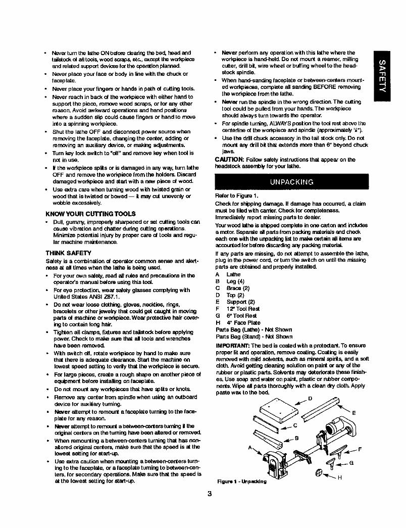
Refer to Figure 1.
Check for shippingdamage. If damage has occurred, a claimmustbe filedwith carder.Check for completeness.Immediatelyrepod:missingparts to dealer.
Yourwood lathe is shippedcompleteinone c_ton and includesa motor.Separate allpads from packingmaterialsand checkeach one withthe unpaddnglistto make certainall items areaccountedforbeforediscardingany packingmaterial.
If any parts am missing, do not attempt to assemble the lathe,plug in the pawer cord,ortum the switchon untilthe missingpads are chtained and properlyinstalled.A lathe
B Leg (4)C Brace(2)D TSP(2)E Support(2)F 12" Teel ReefG 6"ToolRestH 4" Face PlateParts Bag (Lathe) - NOtShownPartsBag (Stand) - Not Shown
IMPORTANT: The bed is coatedwith a protediant.To ensureproper fit and operation,remove coating,Coating is easilyremovedwithmild solvents,such as mineralspirits, and a softdoth. Avoidgettingcleaningsolution on paint or any of therubberor plasticparts, Solventsmay deterioratethese finish-es. Use soap and water on paint, plasticor rubbercompo-nents. Wipe all parts thoroughlywith a clean dry cloth.Applypastewax to the bed,
3
Rgum I -Unpacking
Refer to Figu="es2 - 3.
CAUTION: Do not attempt assembly if parts ere missing.Use this manual to order replacement parts.
• Remove all components from the shipping carton and verifyagainst the parts list on page 3. Clean each component andremo_ shipping preservatives (coatings) as required.
ASSEMBLE STAND
NOTE: Hand tighten all I_ nutsduringstand assembly.Donot completelytighten nutsuntilstand assemblyis complete.
• Piecebcth toppiecesepside downee flooror benchtop.Attach |font and rearsqoportsto topsusingtheca,'dagebolts,flatwashers,lockwashersand hexnuts.
• Attach legs to inside nt tops usingcarriagebols, flatwashers, lockwashers and hex nuts,
• Attachbracesto insideof legsusingcarriagebolts,flatwash-ers, lech washersand hex nuts.
• Turn stand upright, level standandsecure sil nuts.
Suppo_
1\
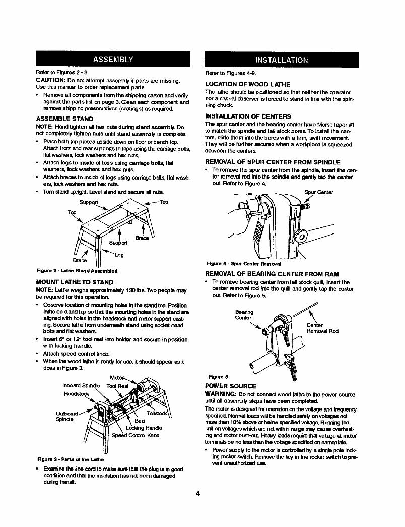
Rgum 2 - Lalhe Stand Asmmbied
MOUNT LATHE TO STAND
NOTE: Lathe weighs apprceimately130 Ibs.Two people mwbe requiredfor this operation,
• Obse_e Iocehend meentingholesin thestand top.Pceitinnlathe on stand top sothat the mountingholesinthe stand arealignedwithhobs inthe headstock and n_tor suppodcast-ing.Securelathe from underneathstand usingsed_ headboltsandflatwashe(s.
• Insert 6" or 12" tool rest into holderand secure in positionwith lockinghandle.
• Attach speed controlknQb.• When the wood lethe is reedj/foruse, it shouldappear as it
doesin Figure3,
Inboard Spinde Toel ReSt
Headstock
Spinde BedHalide
Knob
Rgum 3 - Pmls of the Lathe
• Examine the liee cord to male ,,_Jrethel the ping is in geedcondition and that the insulation has not been damagedduring transit.
Reler to Figures4-9,
LOCATION OF WOOD LATHE
The lathe shouldbe positionedsothat neither the operatornor a casual observer is forced to stand in line with the spin-ningchuck.
INSTALLATION OF CENTERS
The spur center and the bearing center have Morsetaper #1to match the spindleand tail stockbores.To install the cen-ters,slide them intothe bores with a firm,swift movement.They will be further secured when a workpieceis squeezedbetween the centers.
REMOVAL OF SPUR CENTER FROM SPINDLE
• To remove the spur center from the spindle, insert the cen-ter removal rod intothe spindle and gently tap the centerout. Refer to Figure 4.
Spur Center
R_ure 4 - Spur Center RBmovzd
REMOVAL OF BEARING CENTER FROM RAM• To remove bearing center from tall atock quill, insert the
center remavai rod into the quill and gently tap the centerout. Refer to Figure 5.
Beanng_r
Removal Rob
RRure 5
POWER SOURCE
WARNING: Do nat connectwood lathe to the power sourceuntilall assemply steps have been completed,
The motoris designedforoperationontheveltageand IreqnenoJspedled. NotTnatloadswillbe handledsafelyan voltagesnotmorethan10% aboveorbelowspecifiedvolage. Ruanklgtheun! onvoltageswhichare notwthin rangemaycauseoverheat-n:j and motorburn-out.Heavy loadsrequirethat voltageat matorterminalsbe no lessthan Ihevoltage specified on namepla_.
• Powersupplyto the motoris controlledby a single polelock-ingrod_r switch.Rerno_ the kayinthe rockerswitch to pre-vent unauthorizeduse.
4
GROUNDING INSTRUCTIONS
WARNING: Improper conr_dion d equipmed grounding con-ductor can ras.J inthe dsk d electrical shod<. Eq_ment shouldbe grounded while in use to protect operstor from eleddcal shock.
• Check with a qualified elestdcian if grounding instructionsare not understood or i in doubt as to whether the tool is
propedy grounded.
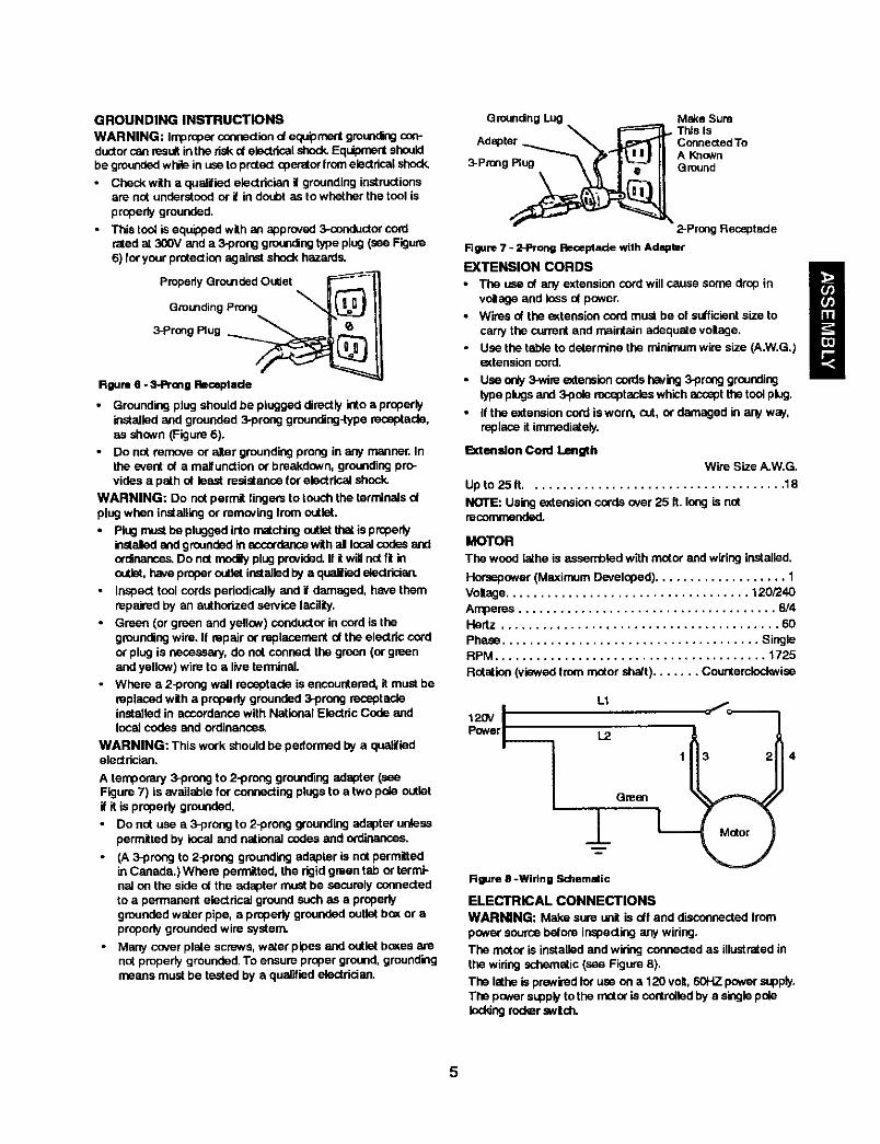
• This tool is equipped with as appmvad 3*conductor cordrated at 300V and a 3-prong grounding type plug (see Figure6) for your protection against shock hazards.
pmpedy Grounded Outlet
Grounding Prong
3-prong Plug __
Rgum 6 - 3-1ProngRmceptado
Groundingplugshouldbe plugged directlyinto a properlyinstalledand grounded3-preeg grounding-typereceptacle,as shown (Figure6).
• Do not ran'x_e or alter groundingprong in any manner. Inthe eventot a maitunctionor breakdown,groundingpro-vides a path ot least resistancefor electrical shock.
WARNING: Do notpermit lingers to touch the terminalsotplug when installingor removing lrem outlet.• Plugmustbe pluggedinto matchingoutistthatis propeby
instaled ond groundedin accordancewithal localcodasandordinances.Do notmodly plugprovided.If itwillnO[ft inoutlet,haveproperoutletinstalledby a qual|led electrician.
• Inspect tool cords pedodicellyand if damaged, have themrepairedby an authorized seP.'iceIacitity.
• Green (or green and yellow)conductorin cord is thegroundingwire. If repairor replacementof the electriccordor plug is necessary, do not conned the green (or greenand yellow)wire to a liveterminal.
• Where a 2-prong wall receptacle is encountered,it mustbereplacedwith a properlygrounded:)-prongreceptacleinstalled in accordancewith National Electdc Code andlocal codes and ordinances.
WARNING: This work should be pedormed by e qualifiedelectrician.
A temporary 3-preng to 2..prenggroundingadapter (seeFigure 7) is available for consentingplugsto a two pole outletif it is properlygrounded.
Do not use a 3-preng to 2-preng groundingadaptor unlesspermittedby local and national codas and ord'mances.
(A 3-prong to 2-prong groundingadapter is not permittedinCanada,) Where permitted, the rigidgreen tab or term'l-naton the side ot the adaptermust be securelyconnectedto a permanent electricalground such as a propedygroundedwater pipe, a properlygroundedoutlet b_( or aproperlygroundedwire system.
• Many coverplate screws,water pipes and outlet bosasarenot properlygrounded.To ensure proper ground,groundingmeans mustbe tested by a qualifiedeleotrician,
Qmunding Lug M_<e SumThis Is
Adspter_ __ConnectedTo
_A Kqown
3-Prong Ground
2-Prong Receptacle
Rgure 7 - 2-Prong Receptacle with Adapter
EXTENSION CORDS
• The use of any extension cord will cause some drop involnge and loss of power.
• Wires of the _tension cord must be ol sutficisnt size to
carry the ourmnt and maintain adequate voltage,
• Use the table to determine the minimum wire size (A.W.G.)extension cord.
• Use only 3-wire eadenslen cords h_iug 3-prong groundingtype plugs and 3-pob mcept asles which accept the tool plug.
• If the extension cord is worn, cut, or damaged in any way.replace it immediately.
Extemdon Cord lengthWire Size A.W.G.
Up to 25 tt..................................... 18
NOTE: Using extension cords over 25 It, long is notrecommended.
MOTOR
The wood lathe is assembled with rector and wiring installed.
Horsepower (Maximum Developed) ................... 1
Voltage ................................... 120/240
Amperes ..................................... 814Hertz ........................................ 60
Phase ..................................... SingleRPM ....................................... 1725
Rotation (viewed Iron', mater shatt) ....... Counterclockwise
L1
120V IPower L2
1±
Rgure B -Wiling Schemstic
Green
ELECTRICAL CONNECTIONSWARNING: Make sureunit is off and disconnectedfrom
power sourcebesominspectingany wiring.The motor is installedand wiring connectedas illustratedinthe widngschematic(see Figure8).
The lathe is prewiredlot use on a 120 volt,60HZ powersupply.The powerst4)plyto the motoris controlledby a singlepoleleddng roder swich.
5
The power lines are inserteddirectly ontothe switch.The0teen groundline must remain securely fastened to the fremeto properlyprotect againstelectrical shock.
• Removethe key to preventunauthorizeduse.
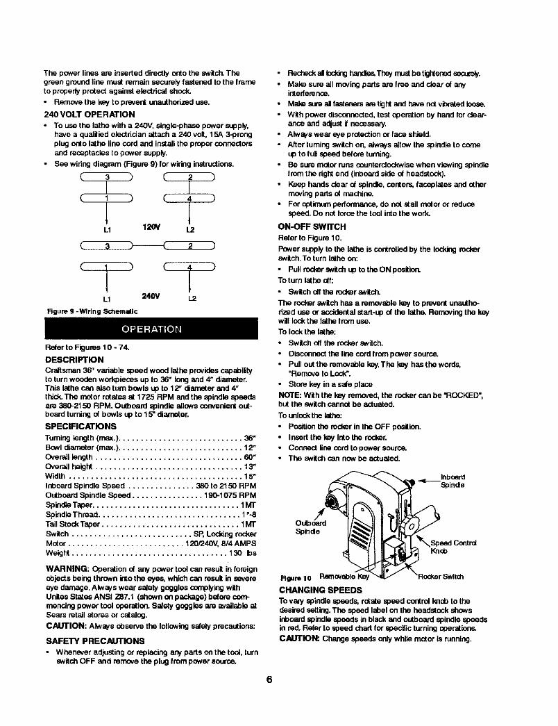
240 VOLT OPERATION
• To use the lathe with a 240V, single-phase pov,,er supply,have s qualified electrician attach a 240 volt. 15A 3-prongplug Onto lathe line cord and install the proper connectorsand receptacles to power supply.
• See wiring diagram (Figure 9) for wiring instructions.
C 3 C 2__L_
C 4 )
L1 1_ _
_ 2 )
L1 240V 1.2
Figure 9 -Wiring S<d'lemallc
Refer to Figures10 - 74.
DESCRIPTION
Craftsman 36" variable speed wood lathe providescapabilityto turn woodenworkpieces up to 36' longand 4" diameter.This lathe can also turn b_wls up to 12" diameterand 4"thick.The motor rofstosat 1725 RPM and the spindle speedsare 380-2150 RPM. Outboard spindle allows convenientout-boardturning of bowls up to 15" diameter.
SPECIFICATIONS
Turning length (max.) ............................ 38"
Bowldiareeter(max.)............................12"Overalllength................................. 60_Overallheight................................. 13"Width ....................................... 15"Inboard SpindleSpeed ............... 380 to 2150 RPMOutboardSpindle Speed ................ 190-1075 RPMSpindleTaper................................. 1MTSpindleThreed ................................ 1".-8Tail Stock Taper ............................... 1MTSwitch ........................... SP, LockingrockerMotor .......................... 120/240V, 8/4 AMPSWeight ................................... 130 bs
WARNING: Operation of any power toolcan result in foreignobjects being thrown into the eyes, which can result in severeeye damage. Always wear satety goggles complyingwithUnites StatesANSI Z87.1 (shown on paskage) before com-mencingpower tool operation.Salaty goggles ate available atSears retail storesor catalog.
CAUTION: Always Observethe followingsafely precautions:
SAFETY PRECAUTIONS
• Whenever adjustingor replacing any parts on the tool, turnswitchOFF and remove theplug from power source,
• FlesheckallIoddnghandles,Thay mustbe tightensdseoJraly.
• Mak_ sure allmovingparts are free and clear of anyintederence.
• Mal® s_.a'eal fastonarsam tightand have nctvbrated loose.
• With power disconnected,test eperetion by handfor clear-ance and adjustit necessary.
• Always wear eye protectionor face shield.• Alter turningswitchon, alwaysallow the spindle to come
up to lull speed before turning.• Be suremeter runscounterclockwisewhen viewing spindle
from the rightend (inboardside of headstock).
• Keep handsclear of spindle,centers, faceplates and otherreeving parts of machine.
• For optimum performance, do not stall motor or reducespeed. Do not forcethe tool into the work.
ON-OFF SWITCH
Refer to Figure 19.
Power supplyto the lathe is controlledby the lockingrockerswitch.To turn lathe on:
• Pull red_r snitchup to the ON position.To turn lathe _f:
• Switch off the rockersNitCh.
The rocker switch has e removable_ to preventunsetho-dzBd use or accidentalstart-up of the lathe.Removingthe kaywill !ock the lathe from use.
To lock the lathe:
• Switch offthe rockerswitch.
• Disconnectthe line cord lram power source.• Pull out the removablekey.The key has the words,
"Remove to Lock".
• Store key in a sale pla_e
NOTE: With the kay removed,the rockercan be "ROCKED",butthe switchcannot be actuated,
To unlockthe Isthe:
• Positionthe rockerin the OFF pneltinn.
• Insert the key into the rocker,• Connect line cord to power source.• The switch can now be actuated.
• _ Spindle
Rgum 10 RemovableI_ _/ _Roc_erSwltch
CHANGING SPEEDS
To valy spindlespeeds, rotatespeed control Imopto thedesiredsetting.The speed label on the headstock showsinboardspindlespeeds in black and outboard spindle speedsin red. Refer to speed chartfar specific turningoperations.
CAUTION: Change speeds only while motor is running.
6

SPINDLE TURNING
If you have never done any amountot wood turning,we sug-gest that you practiceusing the variouswood turningtools.Start witha small spindle turning.
Be sure to studythe follo_vingpages of this manuel.Theyexplain and illustratethe correctuse at the turning tools,thepositioningot the tool rest, and other informationto help yougain e_pedence.
• Select a plese ot wood 2" x 2" x 12".• Draw diagonal lines on each end to locatethe centers.
Diagonal Unes onBoth Ends
• Observe the speed chart (see page 14). For example, a 2"square turning uP to 18" long should run at 1100 RPM for"roughing'. Rotate the wood by hand to make sum that the
corners do not strike tim tool rest and verify that the index-ing pin is not engaged.
Rgure 11
• On one end, make a saw cut epprosJn'_ely 'A," deep oneach diagonal line, This is for the spor o_nter,
• The other end uses the bearing center. Place the point otthe bearing center on the wood where the diagonal linescross`
• Drivethe bearingcenter into the wood.Use a wooden mat-let or a plastic hammer, butput a piece of wood on the endof the bearing center to prctect it from harm.
Rgum 12
• Remove the bearing center and drivethe spur center intothe otherend of the wood. Make sum the spurs are inthesaw cuts. Remove the spur center.
• Make sure the centers and the hole in thespindle and thetail stock ram are clean. Insert the spurcenter into theheadstock and the bearingcenter intothe tail atock.Tspthem in lightlywith a piece ot wood. Do not drivethem in.
• II the tall stock center is not ot the ball bearing type, put adrop of oil or wax an thewood where it contacts the cen-ter.This will It_,ricate the woodwhile it is tumiag.
• Place the woodbetweenthe centers andlockthe t6il stock.
• Movethe bearingcenter intothe woodby turningthe handwheel. Make sure that the bearingcenterand spur center
=seated"into thewood inthe holesmadeeadier. Rotatethe woodby handwhile turningthe handwheel.
• Adjust the tool rest approximately',_"away from the cor-nersof the wood and %"shove the center line.Note theangled positionof the tool rest base. Lockthe tool restbase and the tool rest.
Rgure 13
1_ _'
,oo°TOOL REST _._
Rgure 14
INDEXING
Refer to Figume15,
The spinulepu[k3yhas 24 agu_Jlyspaced slots(15° apart).Theirides(pinpsssesthroughthe headstockengageswithonect the24 slotsemdlocksthespindle fromturningwhileyouput a markon thewod_lec_
i Slots
Rgure lS
Forexample, to locatethe positionot six flutes on a cylinder:.
• Openthe rearcaver.
• Push indexpin untilthe indexpin engages one ef the 24slats inthe spindle pulley.
• Adjustthe 12" tool meatto the centerline ot the workpleceand make e mark.
• Pull indexpin out to release pin,Slowly rotate the work-piece untilpin is located60" (4 holes) from initial position.Engage indexpin into the pulleyand place another markon the workpiece.
• Continue these stepsuntilthere are 6 marks on the work-piece.
• Bowlturningsor wheel turningscan be marked intheS_ rn_qReL
WARNING: The indexingpin mustbe disengagedfor allnther operations on the lathe,
OUTBOARD TURNING
This technique mat_s it possible to do jobs on this machinethat are too large to mount conventionally. It is straight forwardlaospiste turning, except, because of the work size, cautionmust be talon and speeds must be restricted to minimums. Ifyou anticipate doing outboard turning you must use a bowlturning rest (see Recommended Accessories, page 27). Thebowl turning rest is attached to the lathe bed. See Figure 16,page 8.
7
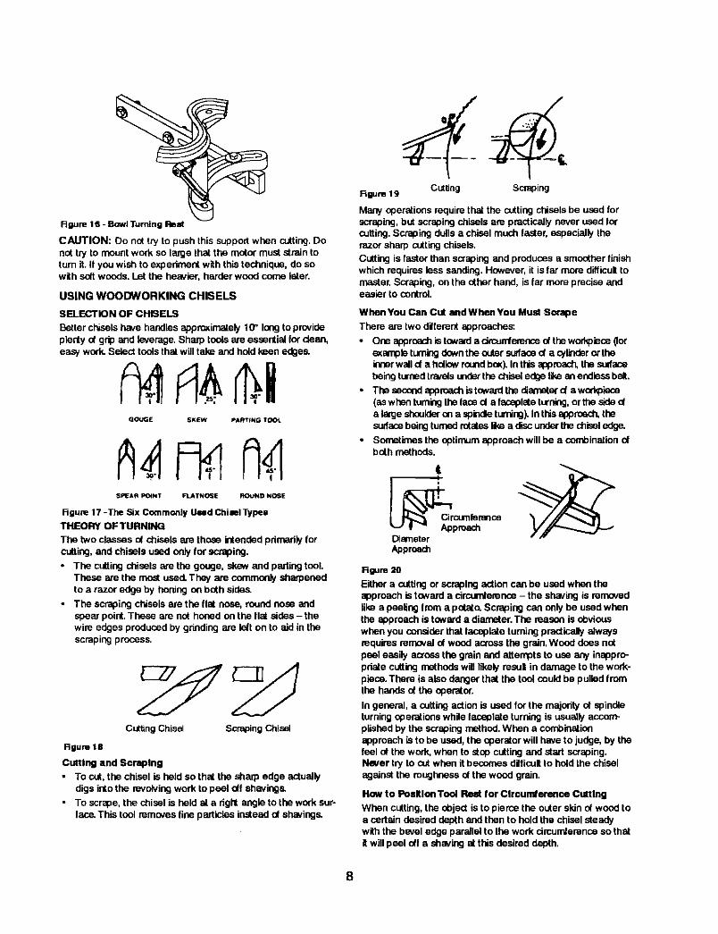
figure 16 - Bowl Turning Rest
Rgure19 Cuttin S "
CAUTION: Do not try to push this support when cutting.Donottry to mountwork so large that the motor must strain toturn it. If youwish to experiment with thistechnique,do sowith softwoods. Let the heavier, herder wood come later.
USING WOODWORKING CHISELS
Many operationsrequirethat the cuttingchiselsbe used forscraping,but scraping chiselsare practicallynever used forcutting.Scrapingdullsa chisel much faster, especiallytherazor sharp cuttingchisels.
Cutting is faster than scrapingandproduces a smootherfinishwhich requiresless sanding.However, it is far more difficulttomaster.Scraping, on the other hand, is lar more preciseandeasier to control.
SELECTION OF CHISELS
Betterchiselshave handles approximately10" longto provideplentynt gripand leverage.Sharp toolsare essentialIordean,easy work.Select toolsthat will take and holdkeen edges.
GOUGE SKEW PA_TfNG T_04_
SPEA fl POINT FLATNOSE ROUND NOSE
Figure| 7 -The Six CommonlyUsed ChimlTypesTHEORY OF TURNING
The two classes ot chisels are those intendedpdmadly Iorcutting,and chisels used only for scraping,• The cuttingchisels are the gouge, skew and partingtool.
These are the mostused.They are commonlysharpenedto a razor edge by honingon both sides.
• The scrapingchiselsare the flat n_e, roundnose andspear point.These are not honedon the flat sides- thewire edgesproduced by grindingare felt on to aid in thescrapingprocess.
Cutting Chisel Scraping Chisel
Rgum 18
Cutting and Scraping
• To cut, the chisel is held so that the sharp edge actuallydigs into the revolving work to peel otf shavings.
• To scrape, the chisel is held at a dgN angle to the work sur-lace. This tool remcves fine particles instead of shavings.
WhenYou Can Cut andWhanYou Must Scrape
There are two ditlemnt approaches:
• One sppr_ch is towarde drcunfemsce oftheworkpiece_orexampleturningdowntheoutersurfaced a cylinderor theinnerwalld a hollowroundbex).In thisapproach,thesulfasehek'igturnedtravelsunderthechisel edgelikean endlessbelt.
• The secondapproachistowardthe diameterd a workpiece(aswhen turningthefaced a fsceplate turning,or the sideda largeshoulderon a spindleturning).In thisapproach,thesudscebeingturnedrotatesIke a discunderthechisel edge.
• Sometimesthe optirnum approachwill be a sent)ination ofboth methods.
t
DiameterApproach
Rgum 20
Either a cuttingor scrapingaction can be used when theapproach is towarda circumference- the shavingis mmavedlike a peelingfrom a potato.Scraping can only be used whenthe approachis towarda diameter.The mason is obviouswhen you considerthat faceplate turningpracticallyalwaysrequires removal of woodacross the grain,Wood does notpeel easily acrossthe grain and attemptsto use any inappro-pdate cuttingmethodswill likelymsul in damage to the work-piece.There is also danger that the tool couldbe pulledfromthe hands of the operator.
In general, a cueing actionis used for the majorityof spindleturningoperations while taceplate turning is usuallyaccom-plishedby the scrapingmethod.When a combinationapproach is to be used, the operator will haveto judge, by thefeel ot the work,when to stopcutting and start scraping.Never try to cutwhen itbecomes difficultto hold the chiselagainst the mughnese ofthe wood grain.
Haw to PosltlonTool Rest for Clrcurnterenoa CuttingWhen cutting,the object is to pierce the outer skinof woodtoa certain desireddepth and then to hold the chiselsteadywith the bevel edge parallelto the work cimundemnceso thatitwillpeel oft a shaving at this desired depth,
8
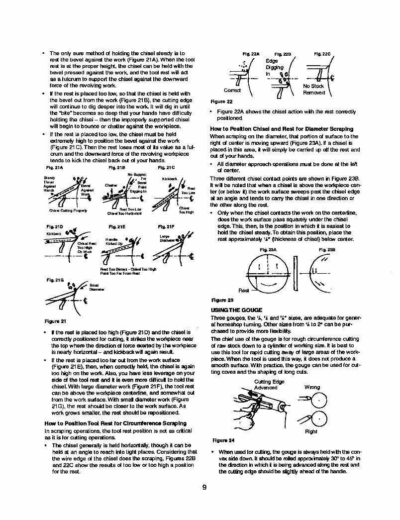
• The only sure methodof holdingthe chisel steady is tomat the b_vel against the work (Figure 21A). When the tonimat is at the proper height, the chisel can be held withthebevel pressed against the work, and the tool restwill actas a fulcrum to support the chisel against the downwardforce of the revolvingwork.
• If the rest is placed too low, so that thechisel is held withthe bevel out from the work (Figure21B), the cuttingedgewill continueto dig deeper intothe work. It will dig inuntilthe "bite" becomes so deep that your hands have difficulyholding the chisel - then the improperlysupportedchiselwill beginto bounce or chatter against the workplace.
• ffthe rest is placed ton low,the chisel mustbe heldextremely high to positionthe bevel against the work(Figure 21C).Then the rest losesrno_ of itsvalue as a ful-crum and the downwardforce of the revolvingworkplecutends to kick the chiselback out of yourhands.
Fig. 21A Rg, 21B Rg. 21C
No aJp_xt
ae_ _ S • . F_ Kickback /iXhr=, '_ Chan /d" Bev_ Kickba=_.^_ml B_ _ • [ pelnl
Ctlisel (_jn_g pl_er _ _ R_I Too LOlbd TOU H G'lz_m d TOO Itl_h
Fig. 21D I_ Fig, 21E RI_ 21F
..... _I_R_ I Handle e
TooHi_
Rest Too D_IW31 * ChbalToo HighP_nl Too Fat From Rmt
Fig. 21G
Rgure 21
If the rest is placedton high (Figure21D) and the chisel iscorrectlyposlioned tar cutting,itstdkes the workplecunearthe top where the directionof torceeKartedby theworkplaceis nearly horizontal- and kickbackwill again result.
• If the rest is placed too far out Iromthe work surface(Figure21E), then, when correctlyheld, the chisel is againton highon the work.Also, you hawetess leverage on yourside of the tool rest and it is even more difficultto hold thechisel. With large diameter work (Figure21F), the tool restcan be above the workplece centedine,and sornewhal outfrom the work sudace,With small diameterwork (Figure21G), the rest shouldbe closerto thework surface.Aswork grows smaller,the rest shouldbe mpositioned.
How to Po_ltlon Tool Rest for Clmunfference Soraplng
In scrapingoperations,the tool rest positionis not as criticalas it isfor cuttingoperations.
• The chisel generally is held horizontally,though itcan beheld at an angle to reach intotightplaces,Considering thatthe wire edge of the chisel does the scraping,Figures 22Band 22(3 show the resultsof ton low or ton higha positionfor the rest.
Fig, 22A
• ioe
c
figure 22
• Figure 22A showsthe chisel actionwith the rest correctlypositioned.
How to PoalUon Chisel and Rest for Diameter Scraping
When scraping on the diameter, that portico of sudase totheright of center is moving upward (Figure 23A). if a chisel is
placed in this area, it will simply be carrisd up oft the rest andout of your hands.
• All diameter approach aparations must be done st the k_tof center,
Three differentchiselcontactpoints are shownin Figure 23B.Itwill be noted that when a chisel is abovethe workpieoscen-ter (or below it) the work sudase sweeps pastthe chisel edgeat an angle and tends to carry the chisel in one directionorthe otheralongthe rest.
• Only when the chisel centasts the work on the cehtedine,does thework surfacepass squarelyunderthe chiseledge.This, then, is the positioninwhich it is easiest tohold the chisel steady.To abtain this position,place therest agpreximataly 'k" (thicknessof chisel)balsw center.
Fill- 2SA FI w. 23B
Uw_
R
Rgum 23
UISING THE GOUGE
Three gouges, the 'k, ',_and =k"sizes, are adequatefor gener-al hornesheptumieg, Other sizes from 'k to 2" can be pur-chased to providemore IleKibinty.The chief use of the gouge is for roughcircumfarenoscuttingof raw stock down to a cylinderof worfdngsize.It is best touse this toolfor rapidcuttingaway of large areas of the work-piece.When the tool is used thisway, it does not produceasmoothsudace,With practice,the gougecan be used for cut-ting covesand the shapingof longcats.
CuttingEdge
P_fflt
Hgum 24
• When ussdfor o-tting,thegougeis alwaysheldwiththecon-veKsidedown.It should he rolledapprodmatel),30=to 45_ inthedirectioninwhich| is beingadvancedalongthe restandthecuttingedge should he slightlyaheadct thehandle.
9
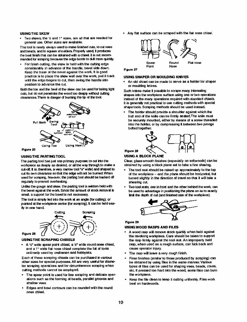
USING THE SKEW
• Two skews, the '/zand 1" sizes, am all that are needed forgeneral use. Other sizes are avallsble,
This tool is nearly always used to ma_ fbished cuts, to cut veesand beads, and to square shoulders. Properly used, i producesthe best finish that can he obtained with a chisel. It is not recom-mended for scraping because the edge tends to dul more qalddy.
For finish cutting, the skew is held with the cutting edgeconsiderably in advance of the handle, bevel side down.Keep the base ol the bevel against the work. It is goodpractice is to place the skew well o_,er the wod_, pull it backuntil the edge begins to cut, then owing the handle intoposition to advance the cut.
Both the toe and the heal d the slew can be used for taking lightcuts, but do not penetrate the wood too deeply without cutting_s.There is danger ol burring the tip of the tooL
Rgure25
USING THE PARTING TOOL
The pwting tool has just one prrnaw purpose: to cut into theworkpiece as deeply as desired, or all the way through to make aaJt-off, It is, the_ore, a very narrow tool ak" wide) and shaped tocut its own clearance so that the edge will not he burned.Whenused for scraping, however, the parting tool should be backed offregularly to prevent overheating.
Unli_ the gouge and slew, the parting tool is seldom hatd withthe beval against the work. Since the _nt of stock removal issmall, a support for the bevel is not neoes_y.
The tool is simply led into the work at an angle (for cutting), orpointed at the workpleoe center (Ior scraping). It can be held eas-ily in one hand.
Cutting Scraping
4--,,
USINGTHE SCRAPING CHISELS
• A '/l' wide spear point chisel, a '/z"wide round nose chisel,and a 1" wide flat nose chisel complete the list of toolsordinarily used by crattsmen and hobbyists.
Each of these scraping chisels can be purchased in variousother sizes Ior special purposes. All am very useful for diame-ter scraping operations and for circumference scraping whencutting methods cannot be employed.
• The spear point is used for line soraping and delicate oper-ations such as the forming of beads, parallel grooves andshallow vses.
• Edges and bowl contours can be rounded with the roundnose chisel.
• Any flat sudaca can be scraped withthe flat nose chisel.
Spear Round Flat nosePoint Nose
figure 27
USING SHAPER OR MOULDING KNIVES
• An old chisel can be made to serve as a holder for shaper
or moulding knives.
Such knives male it possible to scrape many interestingshades into the workpiece surface using _ or two operationsinstead of the many operations required wih standard chisels.it is generally not practical to use cutting mathods with spedalshape tools. Scraping methods should he used instead.
• The holder should provide a shoulder against which thebutt end of lhe krlite can be firmly seated,The knife must
be securely mounted, either by means nt a screw threadedinto the holder, or by compressing it between two prongsbolted together.
USING A BLOCK PLANE
Clear, glass.smooth linishes (especially on softwoods) can beobtained by using a block plane sat to take a fine shaving.
• The tool rest should be raised up apprasimately to the topof the workplece - and the plane should be horizontal, butturned slightly in the direction of travel so that it will tale ashearing cut,
• Two tool rests, one in front and the other behind the work, canbe used to advantage in p_itioning the plane so as to eKaotlylimit the dep(h of cut (and fi_ size of the wod_piece).
Rgum 2g
USING WOOD RASPS AND FILES
• A wood rasp will remove stock quickly when held againstthe revolving workpisce. Cam should be talen to support
the rasp firmly against the tool rest. An improperly heldrasp, when used on a rough sudaoe, can kick back andcause operalor injury,
• The rasp will leave avery rough finish.
• Finer finishes (similar to those produced by scraping) canbe obtained by using files in the same manner. Varioustypes of files can be used for shaping vees, beads, caves,eLc. if pressed too hard into the wood, some files can burnthe workpiece.
• Keep the file clean to keep it cutting uniformly. Files workbest on hardwoods.
10
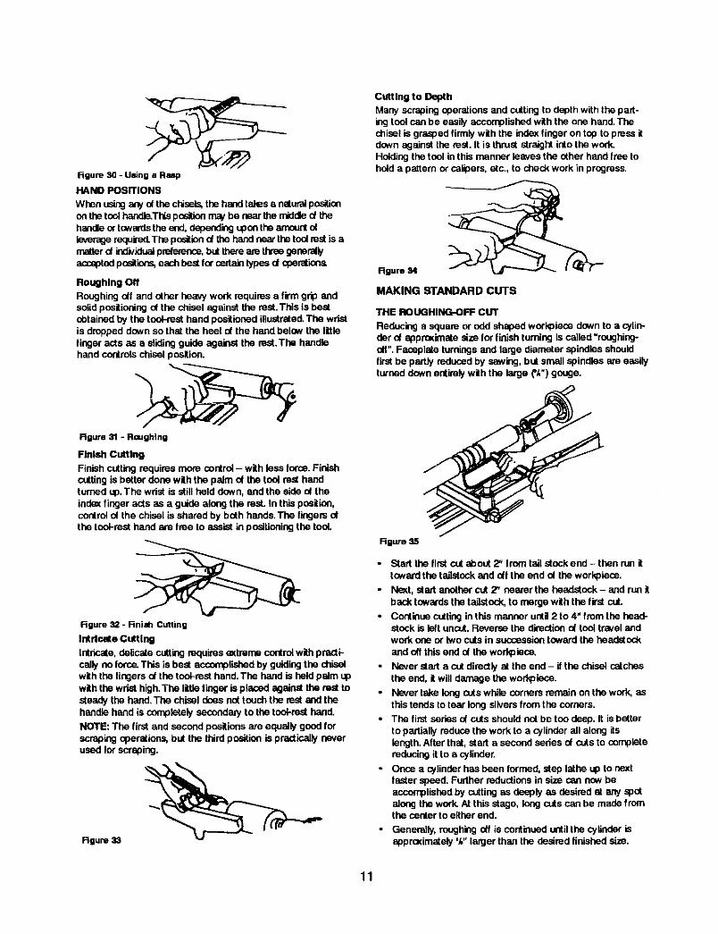
Figure 3Q - Using a Rup
HAND POSITIONS
When usingany ofthe chisels,thehandtales a naturalpositionon thetoniheedl_This pssitionmavbe nearthe middled thehandleor towardsthe end,dependingupan the amesntofleverage required.The positisnd the I'_nd neartheted re.stis amatterd individualprdemnee,bUttheream threegenerallyacceptedpositions,each bestfor certaintypesd operations
Roughing OffRoughingofl and other heavy work requires a firm grip andsolidpositioningof the chisel against the rest.This is bestobtainedby the toet-mat hand positionedillustrated.The wristis droppeddownso that the heel of the handbelow the littlefinger acts as a slidingguide against the rest,The handlehand controlschisel position.
Rgure 31 - Roughing
Finish Cutting
Finish cuttingrequires more control- with less force.FinishcUttingis betterdone withthe palm of the tool rest handturned up.The wrist is stillheld down, and the side ot theindex finger acts as a guide along the rest. In thispselico,controlof the chiselis shared by both hande.The lingers ofthe teet-reet hand are free to assistin positioningthe tooL
Figure 32 - Finilh Cutting
Int deete Cuttingintricate,delicate cuttingrequireseKtremecontrolwithpracti-cally no force.This is best accomplishedby guidingthe chiselwith the fingers of the tool-resthand.The hand is held palm upwiththe wrist high.The littlefinger isplaced againstthe rest tosteady the hand.The chisel does not touchthe rest andthehandle hand is completelysecondaryto the tooFresthand.NOTE: The firstand secondpositionsare equally good forscrapingoperations,hot the third positionis practicallyneverused for scraping.
Rgure 33
Cutting to Depth
Many scraping operations and cUtting to depth with the part-ing tool can be easily accomplished with the one hand. Thechisel is grasped firmly with the index finger on top to press itdown against the rest. it is thrust straight into the work.Holding the tool in this manner leaves the other hand free tohold a p_tem or calipers, atc., to check work in progress.
%..
Rgure 84
MAKING STANDARD CUTS
THE ROUGHING-OFF CUT
Reducing a square or odd shaped workDieos down to a cylin-der of approximate size for finish turning is called "roughing-off". Faosplste turnings and large diameter spindles shouldfirst be partly reduced by sawing, but small spindles are easilyturned down entirely with the large (',_') gouge.
RO_o
• Start the firstcutabout 2" from tail stock end - then run ittowardthe tailatnekand off the end of theworkpieos.
• Nsst, startanothercut 2" nearer the headstock- and run itback towardsthetaiistnek,to mergewith the firstcUt.
• Continue cuttingin this manner until2 to 4" from the head-stock is lettuncut.Reverse the directionof tool travelandwork one or two cUtsin successiontoward the headstockand(_f thisend of the workpieee.
• Never start a cUtdirectlyst the end - if the chisel catchesthe end, it willdamage the wod_leco.
• Never take longcutswhile cornersremain on the work,asthis tends to tear longdivers from the corners,
• The first series of cuts shouldnot tie ton deep. It is betterto partiallyreduce the work to a cylinderall along itslength.After that, start a second series of cutsto completereducingit to a cylinder.
* Once a cylinder has been Iormed,step lathe up to nextfaster speed. Furtherreductionsin size can nowheaccomplishedby cuttingas deeply as desired at any spotalong thework.At this stage, longcuts can be madefromthe center to either end.
• Generally, roughingoff is continueduntilthe cylinder isapproKimately %"lan:jerthan the desired finished size.
11
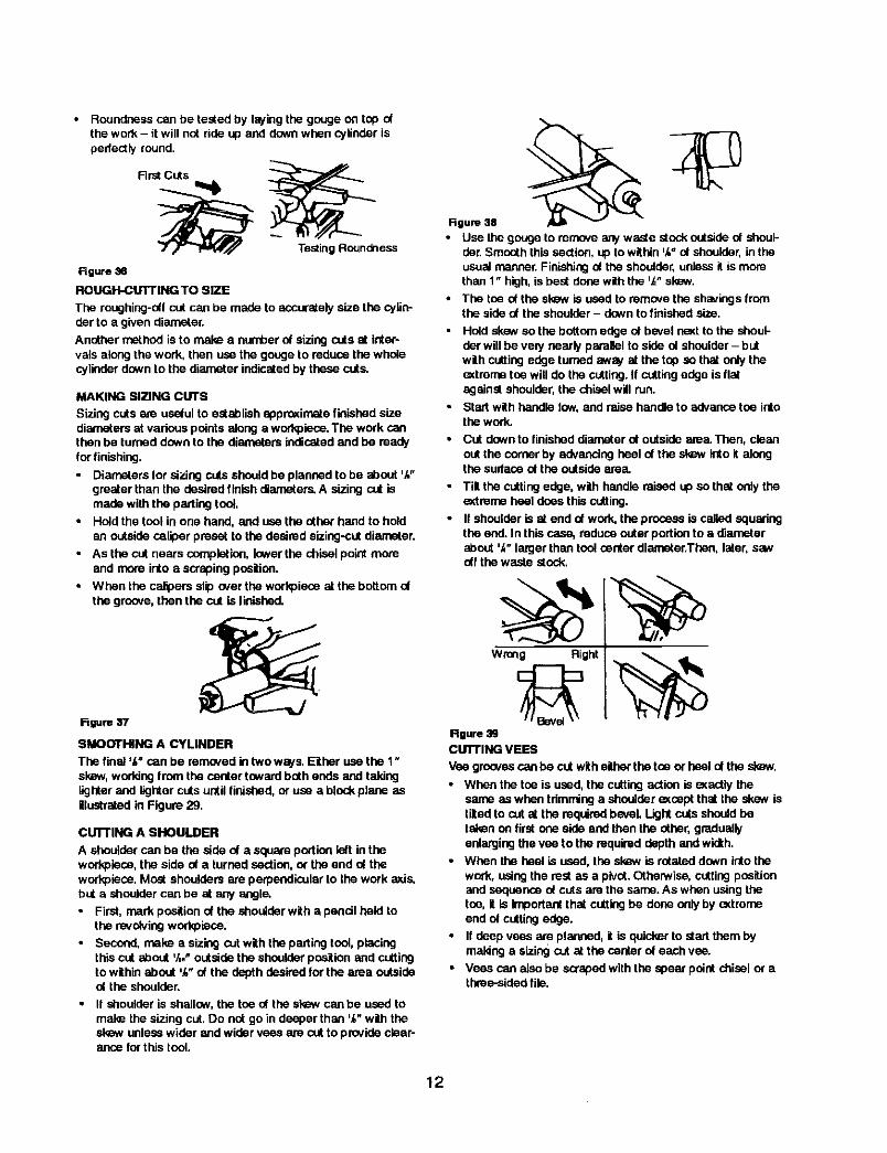
• Roundness can be tested by laying the gouge on top ofthe work - it will not ride up and down when cylinder isperfectly found.
Flrst Cuts
Testing Roundness
Figure 36
ROUGH-CUTTING TO SIZE
The roughing-ooIcut can be made to accuratelysize the cylin-der to a given diareeter.
Another method is to make a numberof sizing cuts at inter-vals alongthe work, then use the gouge to reduce the wholecylinder downto the diameter indicatedby these cuts.
MAKING SIZING CUTS
Sizing cuts am useJulto establish agprexim_e finishedsizediameters at various pointsalong a workpieos.The work canthenbe turned downto the diameters indicatedand be ready •for finishing.
Diameters for sizing cuts shouldbe planned to be about ',_"greater than the desired finishdiameters.A sizing cut ismade withthe partingtoot,
• HoOdthe tool in one hand, and use the other hand to hoOd •an outsidecaliper preset to the desiredsizing-cutdiameter.
• As the cut nears completion,lower the chisel point moreand more into a scraping pnettion.
• When the calipersslip over the workoieseat the bottom oOthe groove, then the cut is linished.
Figure 37
SMOOTHING A CYLINDER
The final ',_"can be removed intwo ways, Either use the 1"skaw, workingfrom the center towardbothends and takinglighterand lightercuts until finished,or use a blockplane asillustratedin Figure 29.
CUI"rlNG A SHOULDER
A shoulder can be the side of a squareportion left intheworkpisce,the side of a tarriedsection,or the end of theworkpisce.Most shouldersare perpendicularto thework axis,but a shouldercan be at any angle.
• First, rnarkpositionof the shoulderwith a pencilheld tothe revolvingworkpieoe.
• Second, make a sizing cutwith the partingtool,placingthiscut about '/,." outsidethe shoulderpositionand cuttingto withinabout '/," of the depth desired for the area outsideat the shoulder.
• If shoulder is shallow, the toe of the skew can be used tomake the sizing cut.Do not go in doeper thon ',_"withthesi_w unlesswider and widervees are cut to provideclear-ance for this tool.
Figure 38
• Use the gouge to remove any waste stock outside of shoul-der. Smooth this section, up to within ',_" oOshoulder, in theusual manner. Finishing at the shoulder, unless it is morethan 1" high, is best done with the q,_"sl_w.
The toe of the skaw is used to rem_x,e the shavings fromthe side of the shoulder - down to finished size.
Hold skew sothe bottom edge of bevel neKtto the shoul-der willbe vely nearly parallel to side oOshoulder- butwith cuttingedge turnedaway at the top so that only theextremB toe willdo the cutting.If cuttingedge is flatagainstshoulder,the chisel will run.
Startwith handle low, and raise handle to advancetoe intothe work.
Cut down to finished diameter of outside area. Then, clean
out the corner by advancing heel of the skBw into it alongthe surface of the outside area.
Tilt the cuttingedge, with handle raised up so that onlytheextrsme heel does this cutting.
II shoulderis at end of work, the process is called aguadngthe end. In thiscase, mduse outerportionto a diameterabout '_" largerthan tool centerdiaree_acThen,later, sawoff the waste stock.
Rgure39CUTTING VEES
Vee groovescan be cut witheither thetoe or heel of the skew.
• When the toe is used,the cuttingaction is exactlythesame aswhen trimminga shoulderaxsspt that the skew istiltedto cut at the requiredbevel. Lightcuts shouldbetakenon firstone side and then the other,graduallyenlargingthe vee to the required depth andwidth.
• When the heel is used, the skmNis rotated downinto thework, usingthe rest as a pivot.Otherwise,cuttingpositionand sequence ot cuts am the same. As when usingthetoe, it is importantthat cuttingbe doneonly by extremeend of cuttingedge.
• If deep vees are planned, it is quickerto start thembymaldng a sizing cut at the centerof each vee.
• Voes can alsobe scrapedwith the spear point chisel or athree-sidedfile.
12
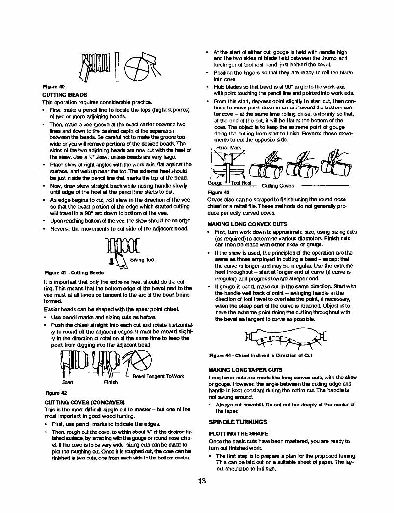
Roure 40CUTTING BEADS
This operationrequires considerablepractice.
• First, make a pencil line to locatethe tops (highestpoints)of two or more adjoiningbeads,
• Then, male a yea greave st the axact centerbetweentwolinesand downtothe desired depth d the separationbetweenthe beads.Be carefulnotto make the groevetonwide oryou will removepodionsof the desiredbeads.Thesidesolthe two adjoiningbeads are now cutwiththe heeldthesksw.Use a %"skew, unlessbeadsam very la,'ge.
Placeskew st rightangleswiththework axis,flatagainstthesudase, andwellup near the top.The axtrerne heelshouldbe just it_sidethe pencil linethat marksthe topof the bead.
Now, draw slew straightback whiio raisinghandle slowly-until edge nt the heel at the pencil line starts to cut,
• As edge begins to cut, roll sl_w in the directionol the veeso that the _act portion of the edge which started cuttingwill travel in a 90" arc downto bottom of the vea.
Upenreachingbottomd thevee,the slew shouldbe en adge.Reversethe movementsto cutside ol the adjacent bead.
_S_ng Tod
Rgure 41 - Cutting Beads
It is important that only the _treme heel should do the cut-tiag.This means that the bottom edge nt the bevel naxt tothevea must at all times be tangent to the arc nt the bead beinglormed.
Easier beads can be shapedwith the spear pointchisel.
• Use pencilmarks and sizing cuts as belore.
• Push the chisel straightinto each cut end rotate horizontal-ly to roundoff the adjacent edges. It mustbe moved slight-ly in the directionof rotation at the same time to keep thepoint from digging into the adjacent bead.
Start Rnish
Rgure 42
CUTTING COVES (CONCAVES)This is the m_t difficultsinglecut to master- but one of themost important in goodwood turning.
• First, use pencilmarks to indicatethe edges.
• Then, roughoutthecave, towithinabout ',_"ct thedesiredfin-ishedsudace,byscrapingwi_ thegougeor muadnese d'Ls-el. If theceve is to bevery wide,alziogcutscen he madetoplatthereeghingout.Once it is roughedout, thecovecan hefinished in twocuts,one from eachsideto thebottomcenter.
• At the start of either cut, gouge is held with handle highand the two sides of blade held between the thumb end
fore_ingar of tool rest hand, just behind the bevel.
Position the fingers so that they are ready to roll the bladeinto cove.
* Hold bladessothst bevel is at 90° angle to thework axiswithpointtouchingthepencil line andpointedk'itowork a_is.
• Fromthis start, depresspoint slightlyto stad cut, thencoo,tldueto movepoint down in an arc towardthe bottomcen-ter cove - at the same time roilingchiseluniformlyso that,at the end ol the cut, it willbe flat at the bottomof thecove.The object is to keep the axtrerne point of gougedoingthe cuttingfrom start to finish. Reversethese move-mentsto cut the opposite side.
_R_t CUttingCoves
Rgure 43
Coves alsocan be scraped to finishusingthe round nosechisel or a rattailfile.These methods do nutgenerallypro-duce perfectlycurvedcoves.
MAKING LONG CONVEX CUTS
•Firat, turn work downto eppraximate size, using sizingcuts(as required)to determinevariousdiameters` Finishcutscan thenbe madewith either skew or gouge.
• If the slew is used, the pdncipiosof the operatlen are thesame as those employedin cuttinga bead - exceptthatthe curve is leager and maybe irregular.Use the eKtremeheel throughout- start at longer end of curve (if curve isirregular)and progresstowardsteeper end.
• If gouge is used, make cut in the same direction.Start withthe handle well back of point- swinginghandle inthedirectiondi tool travelto overtake the point, if necessary,when the steep part of thecurve is reached.Object is tohave the axtrerne point doingthe cuttingthroughoutwiththe bevel as tangent to curveas possible,
Rgure 44 - Chitl inclined in Direction of Cul
MAKfNG LONG TAPER CUTS
Long toper cuts are made UI_ long convax cuts, with the skswor gouge, However, the angle between the cutting edge andhac,dle is kept constant during the entire cut.The handle is
not swung around.
• Always cut downhill. Do nat cut too deeply at the center ofthe taper.
SPINDLETURNINGS
PLOTrlNG THE SHAPE
Once the basic cutsha_'ebean mastered, you are ready toturn outfinished work.
• The firststep is to prepare a plan for the proposedturning.This can be laid out on a suitablesheet ol paper.The lay-out shouldbe to full size.
13
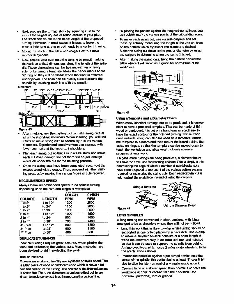
• Next. prepare the turningstockby squanng itup to thesize ot the largest square or round section in your plan.The stock can be cut to the exact length of the proposedturning.However, in mast cases, it is best to leavethestock a littlelong at one or both ends to allowfor trimming.
• Mount the stock in the lathe and rough it otf to a maxi-mum-sizecylinder.
• Now,project your pian onto the turning bypencil markingthe various critical dimensionsalongthe lengthal the spin--die. These dimensionscan be laid out with an ordinaryruler or by using a template. Make the pencilmarks shout'/z"longso they willbe visiblewhen the work is revolvedunder power.The lines can be quicklytraced around thespindleby touching each line withthe pencil.
Diameters1'_" 2" 1',_" 2'k'1_'1",_="2=,_," 1",_'17_'1"_,'1"
I I _ I 1 = I
I _ 14'u' o -)=.-ISizingCuts
Rgum 45
• After marking, use the parting tool to make sizing cuts atall ot the important shoulders.When learning, you will findit best to make sizing cuts to aocurately plot the variousdian_ters` Experienced wood workers can manage withlewer such cuts at the important shoulders,
• Plan each sizing cut so that it is in waste stock and makeeach cut deep enough so that there will be just enoughwood left under the cut for the finishing process.
• Once the sizing cuts have been completed, rough-out theexcess wood wiLh s gou9e. Then, proceed with the finish-
ing process by maldng the vadous types ut cuts required.
RECOMMENDED SPEED
Always followrecommendedspeed to do spindle turningdependingupon the size and length of worl_iece.
ROUGH FINISHSQUARE LENGTH RPM RPM1 to 2" 1 to 12" 1300 20001 to2" to 24" 1100 20001 to 2" to 38" 1000 20002to4" 1 to 12" 1000 18002 to 4" to 24" 900 16002t04" to38" 700 1400N' Pins 1 Io12" 800 14004" Plus to 24" 600 11004" Plus to 38" 400 800
DUPMCATETURNINGS
Identical turnings require great accuracy when plotting thework and pedorming the various cuts. Many methods hovebeen devised to aid in pedecting the work.
Use cA'Patterns
Prdassionsiworkersgenerallyuse a paltem or Isyoutheard.Thisis a thinpleseof wood or cas:iboardupon whichis dmNns fulFsizeh_ sectiond theturning.Thecontcorofthe fid...dr_dsudaseis drawnfist. Then, the diametersat variousoriUcalpointsatedrawnto sc_e asverticallinesintersectingthe contourr.-_
• Byplacingthe patternagainstthe roughed-out cylinder,youcan quicldymarkthe variouspointsut the criticaldiameters,
• To make each sizing out,use outsidecalipersand setthese by actuallymeasuring the lengthel thevertical linesan the paltem which representthe diameters desired.Make the sizingcut downto the properdiameter by usingthe calipersto determinewhen the cut is finished.
• Alter maidngthe sizing cuts, hang the pattern behindthelathe where itwillserve as a guide for completionut theworkpiece.
Rgura 46
Using aTemplate and a Diameter Board
When many identicalturningsare to be produced, it is conve-nientto have a preparedtemplate.This can be made ofthinwoodor cardboard.It is outon a band saw or scrollsaw tohove the e¢act contouror the finished turning.The numberone finished turningcan alsobe used as a template.Attachthe template to a boardand then mountthe board behindthelathe,on hinges,so that the template can be moved downtotouch the workpiaceand allow you to closelydbser'.'eprogressof yourwork.
If a greatmany turningsarebeingproduced,a diameter boardwill savethetime usedfor resettingcalipers.Thisis simply a thinbo_d along theedge ofwhich a oumper d semicircular cutshavebeen preparedto representall thevariouscalipersettingsrequiredhx measuringthe sizingcuts.Eachsemi-drcalarcut isheld against thew0d<pleceinsteed ut usingthecalipers.
Rgum 47
Usinga Templete
Usinge Diameter Board
LONG SPINDLES
A long turningcan be worked in shortsections, with jointsarrangedto be at shoulderswhere they will not be noticed.
Long thin work that is likely te whip while tumthgshouldbesupportedal one or two places by a backstick.This is easyto make. A simple backstickconsistsut a short length ofwood mountedverticallyin an emtratool rest and notchedso that it can be used to supportthe spindle from behind.An improvedtype, which uses 2 roller =+kalewheels to formthe notch,also is shown.
• Position the backstid_against a pre4umed portionnear thecenterofthe spindle,thisportionbeing at least'/+"over linishsizeto allowforlater removalof any marksmade upon it.
• Operate lathe at a slower speedthan normal.Lubricatetheworkpleceat point of contactwith the backstick+Usebeeswax (preferred), lard or grease.
14
Alter completing the turning, remove the bankstick and fin-ish off the original point of contact. Sand off aw slightburns remaining on workpiece,
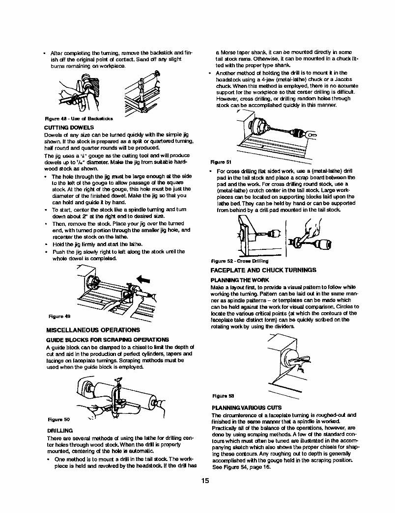
CUTTING DOWELSDowelsof any size can be turnedquicklywiththe simplejigshown.It the stock is prepa,-odas a splitor quartered turning,half round and quarter roundswillbe produced.
The jig uses a ',_"gouge as the cuttingtool and will producedowelssp toT,_,"diameter. Make the jig from suitable haJ'd-wood stockas shown.
• The hole throughthe jig mustbe large enough st the sideto the left of the gouge to allowpassage of the squarestock. At the right of the gouge,this hole must be just thediameter of the finished dowel.Make the jig so that youcan holdand guide itby hand.
• To start, center the stock like a spindle turning and turndownabout 2" at the rightend to desired size.
• Then, remove the stock. Place yourjig over the turnedend, with turned portionthroughthe smaller jig hole, andrecenterthe stock on the lathe.
• Hold the jig firmly and start the lathe.• Push the jig slewly rightto left along the stock untilthe
whole dowel is completed.
Rgure 49
MISCELLANEOUS OPERATIONS
GUIDE BLOCKS FOR SCRAPING OPERATIOI_
A guideblock can be damped to a chisel to limitthe depth ofcut and aid inthe productiond perfect _linders, tapers andfacingson leceplate turnings.Scrapingmethods mostbeused when the guide block is employed.
figure 50
DRILLING
There are se,remlmethods of usingthe lathe for drillingcen-ter holes throughwood stock.When the drill is properlymounted, centeringof the hole is automatic,• One method is to mount a ddll in the tail stock The work-
piece is held and revolvedby the headstock. If the ddll has
a Morse taper shank, it can be mounted directly in sometail stock rams. OthenNise, it can be mounted in a chuck fit-
ted with the proper type shank.
• Another method of holding the drill is to mount it in theheadstock using a 4-jaw (metal-lsthe) chuck or a Jacobschuck When this method is employed, there is no accuratesupport for the workpiece so that center drilling is difficult.Hcwover, crose drilling, or drilling random holes throughstock can be accomplished quickly in this manner.
Figure 51
• For crossddllingfist sidedwork, use a (metal-lathe) drillpad in the tail stock and place a scrapbne_dbetween thepad and the work. Forcross drillinground stock, use a(metal-lathe) crotchcenter inthe tall stock Large work-pieces can be locatedon supportingblocks laid upon thelathe bed.They can be held by band or can be supportedIrom behindby a ddllpad mounted in the tall stock.
Rgare 52 -Cross Drilling
FACEPLATE AND CHUCK TURNINGS
PLANNING THE WORK
Make a I;_ont first,to providea visual pattem to followwhileworkingthe turning.Pattern can be laid out inthe same man-net as spindle patterns - or templates can be madewhichcan be held againstthe work for visual comparison.Circles tolocatethe variouscritical points (st which the contoursof thefaceplate take distinctform)can be quicklysorbed on therotatingwork by usingthe dividers.
_9_e
PLANNINGVARIOU$ CUTS
The circomi'erenceol a laceplate turning is roughed-outandfinishedin the same manner that a spindle is worked.Practicallyallof the balance of the operations, however,aredone by usingscrapingmethods.A few of the standard con-tourawhich must oftenbe tuned are illustratedin the accom-panying sketchwhich also shewsthe properchiselsfor shap-ingthese contours.Any roughingout to depth is generallyaccomplishedwiththe gougeheld inthe scrapingposition.See Figure 54, page 16.
15
Round Nose Sposr-Pdnt MeasuringChisel Chisel Depth
Rgure 54
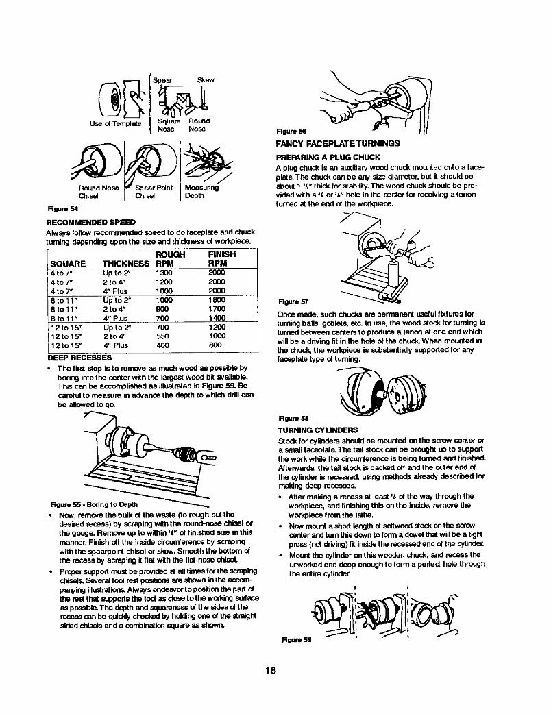
RECOMMENDED SPEED
Always follow recommended speed to do |aneplete and chuckturning depending upon the size and thickness of workpisce.
ROUGH FINISHSQUARE THICKNESS RPM RPM4t07" Up to2" 1300 20004t07" 2 to 4" 1200 20004t07" 4" Plus 1000 2000
Up to 2" 1000 18008to11" 2to4" 900 17008 to 11" 4" Plus 700 140012to 15" Up to 2" 700 120012 to 15" 2to4" 550 100012to 15" 4" Plus 400 800
DEEP RECESSES
• The first step is to mmo,_ as much wood as possible byboring into the center with the largest wood bit available.This can be accomplished as iliustrsi_ed in Figure 59. Becarelul to measure in advance the depth to which ddll canbe allowed to go.
Figure55 -_
• Now, removethe bulk ol the waste _torough-outthedesired recess)by scrapingwiththe round-nosechisel orthe gouge.Remove up to within 'Y"nt linishedsize in thismanner.Finish df the insidecircun_emnce by scrapldgwiththe spearpointchisel or skew,Smooth the bottomo(the recess by scraping it flat with the Ilal nose chisel.
• pruper supportmustbe providodat ell timesfor the scrapingchisels.Severaltoolrest positionsare showninthe auccom-pawing illustrations.Alwaysendeavorto positionthepad ofthe rest thatsupportsthe rod as _ totheworking surfaceas possible.Thedepth and squarenessd the sides d thereoss_can be quicklycheckedby haldingoneof the straightsidedchiselsand a combinationsquare as shown.
Rgure 56
FANCY FACEPLATE TURNINGS
PREPARING A PLUG CHUCK
A plug chuck is an at_iliaq/wood chuck mounted onto a faos-plste. The chuck can be any size diameter, but it should beabout 1%" thick for stability. The wood chuck should be pro-vided with a '_; or _,_"hole in the center for receiving a tenon
turned st the end of the workpieos.
Rgure 57
Once made, such chucks are permanent usefulf_tures forturningballs, goblets, etc. In use, the wood stock for tuming isturnedbetween centersto producea tenon at one end whichwlilbe a drivingfit inthe hole of the chuck,When mounted inthe chuck, the workp;aceis sobelantialiysupportedfor anyfaosplstetype d turning.
Rgum s8
TURNING CYUNDIBRIS
Stockfor cylindersshould be mountedon the screw center ora small laceplale.The tail stock can be broughtup to supportthe work while the circunterance is being turned and finished.Afteiwards,the tail stock is backed off and the outerend ofthe cylinder is recessed, using methodsalreadydescribed |ormakingdeep recesses.
• After making a recess at least ',_d theway throughtheworkpiece,and finishingthis on the inside,mmave theworkpiecefrom the lathe,
• Nowmounta shodlengthd sdtwond stockon the screwcenterandturnthisdownto |orma dowelthat willbe a tightpress(notdriving)fit insidethe recessedend o( the cylinder.
• Mount the cylinderon thiswonden chuck, and recess theunworkad end deep enoughto |orm a perfect hole throughthe entire cylinder.
I I
R_m Sg
16

RECHUCKING
Rechucidng is the general term used to descnbe any addition-al work mounting that is necessary to complete a turning pro-jeot.The method of working ojlinders, and the use of a plugchuck as already described are typical examples. Anothergood eKample is the rechuddng of a bowl,
• The work is mounted on a wood bac_dng block secured to
the large faceplate and it is turned in the usual manner. Allsudases ere cut e_cept the back side (which is against themounting block), The work is then removed from themounting block.
• An aL_itiary chuck of softwood is now made in the samemanner that the cylinder chuck is made. This chuck musthave a turned recess properly sized to accommodate therim of the bowl in a tight press fit.
• When the bowl is mounted in this chuck, the bottom can
be cleaned off and slightly recessed to complete thedesired contours.
Rgure 60TURNING A RING
One method of turning a ring requires a spindle chuck,
• The work stock is first mounted to a bacldng block held bythe large taceplste and is turned to shape on the outerside. The inside diameter of the ring is also shaped - all
the way through to the bacldng block.
• The work is then removed from the backing block.
• A spindle chuck is now prepared so that it will be a tightpress to fit inside the ring.The ring is raversed and mount-ed on this chuck. With the ring mounted, the remainingcontours can be turned to shape.
Rgure el
Another method of turning a ring makes use of a recessedchuck,
• The work stock is mounted ne a sorew center and oce heit of
the ring is |ormed, but the ring is not cut away from is center.
• The stock is then removed, and a mcesssd chuck - mountedon the large facaplete - is prepared to receive the ring in atight press tit.
• Alter being shucked, the remaining face of the ring can beturned to the proper contour, thus cutting away the centerportion.
• In work of this type, take constant measumrneats or, betteryet, use a template to guard against over or under cutting.
1 2 3 4Rgure 62
TURNING BALLS
• Wooden balls of large size are lirst roughly turned between
centers, using standard procedures.
• Smaller balls can be mounted as taseplates on the small
facoplate or screw center.
• Unes drawn to indicate the center and ends of the ball
shape are helpful in plotting the curve.
• A template should always be used for accurate visualobservation of the work progress.
Figure64If theballis mountedas a facoplateturning,almost the entiresurfacecan be turnedbefore it becomescecessaryto rechuckit.
Flechuddngcan be be accemplishodina dsepcupchuckwhichwillholdthetirishedportionof theballin s tightprosetit.
Another methodof reshuddngis to use a shallow cupchuckwhichwillnot supportthe ball alone, but must be used incon-junctionwiththe tall stock,
• When usingthe shallowchuck, a wsed blockis fitted to thetail stock sothat the ball can revolveupon it. This blockshouldbe lubricatedwith bees'vax or grease.
• In usingthe shallONchuck method,the ball is constantlyshifted- never more than ',_turn - and alwaysin a definitepattern.
Woodblod(
B.B.
Center Shallow Beadng CenterRgure 64
• Since turningbstween senters makes the work a periectsphereacross the grain,the ball must be mountedinthechuckso that the firstscrapingcuts will round it up in theoppositedirection.
TURNED BOXES
Turned boKes irlvoive deep reses_ng together with a special sys-tem of working the lid and body of the boKtogether as one unit.
• The inside of the lid is turned first.
17
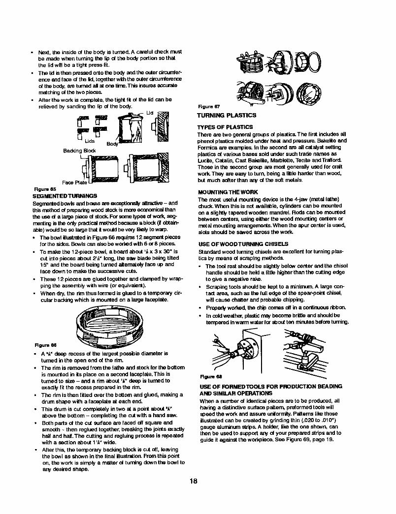
• Next, the inside of the body is turned. A care/ul check mustbe made when turning the lip of the body podiorl so thatthe lid will be a tight press fit.
• The lid is then pressed onto the body and the outer circumfer-ence and face of the lid, together with the outer drcumferenceof the body, are turned all at one tk_e.This insures accuratematching of the two pieces.
• After the work is complete, the tight fit nt the lid can berelieved by sanding the lip of the body.
BadgingBlock
Route 65SEGMENTED TURNINGS
Segrnehted bowls and boKes are exceptionally attractive- andthis method of preparing wood stock is more economical thanthe use d a large piece of stock. Far some typos of work, seg-meriting is the only practical method because a block (f obtain-able) would be so laKje that it would be very lilely to warp.
• The bowl illuetrsted in Figure 66 requires 12 segrnont pieseslot"the sides. Bowls can also be worked with 6 or 8 pieces.
• To make the 12-piece bowl, a board about _/,x 3 x 30" iscut into pieces about 2'/," long, the saw blade being tilted15 = and the board being turned altemetely lace up andface down to make the successive cuts.
• These 12 pieces am glued together and clamped by wrap-ping the assembly with wire (or equivalent).
• When dry, the rim thus Iormed is glued to a temporary cir-
cular b ad,,,ingwhich is mounted on a large laceplate.
Rgure e6
• A "/,"deep recess of the largestpossible diameter isturned inthe open end of the rim.
• The rim is removedfrom the lethe and stock forthe bottom
is mounted in its place on a second laceplete. This isturned to size - and a rim about '/," deep is turned toexactlyfit the recess prepared in the rim.
• The dm is then fitted over the bottomandglued, making adrumshepe with a faceplate st each end,
• This drum is cut cee'plately in two at a point about =,_"above the bottom- completingthe cutwith a handsaw.
• Bothparts of the cut surface are faced offsquare andsmooth- then reglued together,breakingthe jointsexactlyhall and hall The cuttingand regluingprocessis repeatedwith a sectionabout 1'/*"wide.
• Alter this, the temporanj backlogblock is cut oft, leavingthe bowl as shown inthe linal illustretion.Fromthis pointon, the work is simply a matter of turningdownthe bowl toany desired shape.
Rgure 67
TURNING PLASTICS
TYPES OF PLASTICS
There are two general groupsof plastics.The first includesallphenolplastics mnided underheat and pressure.BakeliteandFormicaare examples. In the second am all catalystsettingplasticsef variousbases sold undersuch trade names asLucite,Cetalin, Cast Bakelite,Marbiette,Tenite andTraltord.Those in the secondgroup are mostgenerally used for creftwork.They are easy to turn, being a Iffiie harder thanwood,but much salter than are/of the soft metals.
MOUNTING THE WORK
The most useful mountingdevice is the 4-jaw (metal lathe)chuck.When thisis not available,cylinderscan be mountedon a slightlytaperedwooden mandrel. Reds can be mountedbetween centers, usingeither thewood mountingcenters ormetalmountingarrangements.When the spur center is used,slotsshouldbe sawed acrossthe work.
USE OFWOODTURNING CHISELS
Standard wood turning chisels are excellent for turning pies-tics by means of scraping methods.
• The tool rest should be slightly below center and the chiselhandle should be held a little higher than the cutting edgeto give a negative rake.
• Scraping tools should be kept to a minimum. A large con-tact area, such as the lull edge of the epear-polnt chisel,will cause chatter and probable chipping.
• Properly worked, the chip comes off in a continuous rbbon.
• In cetd weather, plastic may hecome brittle and shsold betempered inwarm water for about ton minutes before turning.
Rgure68
USE OF FORMEDTOOLS FOR PRODUCTION BEADINGAND SIMILAR OPERATIONS
When a number of identicalpiecesare to be produced,allhaving a distinctivesurfacepettem, pre/ormed toolswillspeedthe work and assure unilorm_y.Pettems likethoseillustratedcan be created by grindingthin (.020 to .01(7')gauge aluminum strips.A holder,likethe one shown,canthenbe used to support any of your prepared stripsand toguideit against the workpiece.See Figure 69, page 19.
18
Rgure 69
TURNING BALLS
Plastic balls are rough turned in the usual mannerand thenbroughtto perfect roundnessby using a tube tool,The tubeshouldbe slightlyless in diameterthan the finished size ofthe ball. It can be brass or steel, ground square acrosstheend. The tool is used with orwithout a rest, and is workedbyswingingit from side to side.
Figure 70
POLISHING PLASTICS
Start withsanding.
• First use 150-grit dry paper to removetool marks.
• Then finishoffwith 150-grit and 400-grit papers, in succes-sion. These abrasives should be wet.
• Press lightlyto avoidoverheating and marringthe work.
• Buffinggives thefklaipolish,usingthe polishingcompoundscommonlysuppliedforthispurpose.Do notpresstoo hardorholdthewheel at one spot too long- keep movingaround-otherwise the plasticmightbecome heat marled.
SANDING, BUFFING AND POLISHING
USINGTHE LATHETO SANDTURNINGS
• Turalngs shouldbe sandedwith the Isthe runningin sec-ond I(_Nestspeed.
• A largesheet of sandpaperis usefulfor smoothingcylinders,
• All othersanding operationsare done with a narrowstripoi abrasive paper.The best finishinggri is 3/0 for soft-wood, 4/0 for hardwoods.Worn 2/0 paper is oftenused,and is the equivalent of 3/0 or4/0 new paper.
Rgure 71
The aopicatianof the sandpaperstrip is showninthe ilustretians.
• Care must be exercised in order to pr_ent dubbingthecornersof beads, shoulders, etc.
R0are 72
WoodFibers
r@Sandpaper
J®Fiberstilted aridCut Off
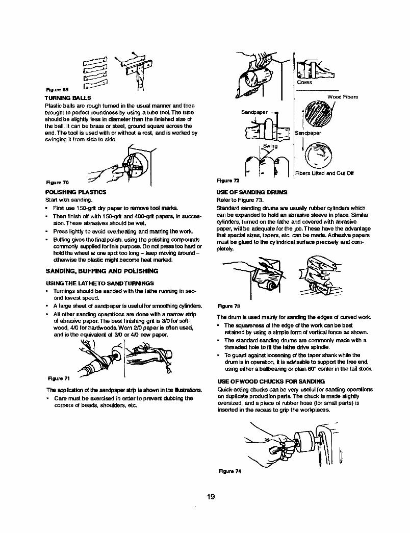
OF BANDING DRUMS
Refer to Figure 73.
Standard sanding drums are usuallyrubber cylinderswhichcan be expandedto holdan abrasive sleeve inplace. Similarcylinders, turned on the lathe and covered with abrasivepaper,willbe adequetefor the job.These have the advantagethst special sizes, lagers, etc. can be made.Adhesivepapersmustbe glued to the cylindrical surfaceprecisely and com-pletely.
Rgure 73
The drumis usedmainlyfor sandingthe edges oi curvedwork.
• The squarenessof the edge of thework can be bestretainedby usinga simpleform of vertical fence_ shown.
• The standard sandingdrums are commonlymade with athreaded hole to fit the lethe drivespindle.
• To guard against leeeen_g of thetaper shankwhile thedrum is inoperation,it is advisableto supportthe free end,usingeither a baibearing orplain 60'=centerin the tail stock.
USE OFWOOD CHUCKS FOR SANDING
Quick-acting chucks can be very useful for sanding operationson doplicate production pads. The chuck is made slightlycversized, and a piece oi rubber hose (for small parts) is
inserted in the recess to grip the workpieoss.
J
19
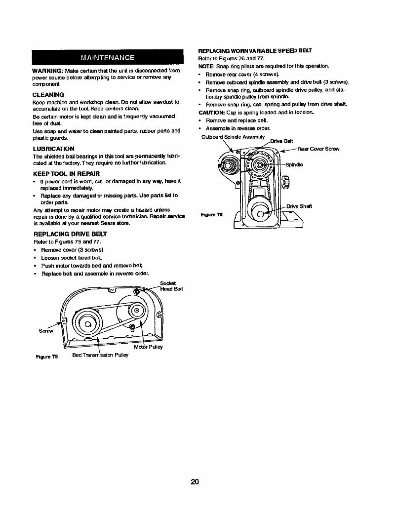
WARNING: Make certainthat the unitis disconnectedfrompower sourcebefore attemptingto service or remove anycomponent.
CLEANING
Keep machine and wort_shepdean, Do not ailow sawdust toaccumulate on the tool,Keep centers clean.
Be certain motor is kept clean and is frequentlyvacuumedline of dust.
Use soap and water to clean painted parts, rubberparts andplasticguards.
LUBRICATION
The shieldedball beadngs in thistool are permanently lubri-cated at the factow.They requireno further lubricefine.
KEEP TOOL IN REPAIR
• If pcwer cord is worn, cut, or damaged in any way, hove itreplaced immediately.
- Replace any damaged or missing parts. Use parts list toorder parts.
Any attempt to repair motor may create a hazard unlessrepair is done by a quaiified service technician. Repair serviceis available at your nearest Sears atom.
REPLACING DRNE BELT
Refer to Figures75 and 77.
• Remove cover (3 screws)Loosensocket head boit.
Push motor towardsbed and remove belL,
• Replace belt and assen_)le in roversoorder.
SScrew
Rgure 75 Bed Transmission Pulley
Socket
Mat_ r pulley
REPLACING WORN VARIABLE SPEED BELT
Refer to Figures 76 and 77.
NOTE: Snap ring pliers are required for this operation.
• Remove rear cover (4 screws).
• Ren'Kx,e outboard spindle assembly and drive bet (3 screws).
Remove snap ring, outboard spindle drive puller, and sta-tionary apindie pulley from spindle.
Remove snap ring, cap, apdng and pulley from drive shaft.
CAUTION: Cap is spring loaded and in tension.
• Remove and replace belt.
• Assemble in reverse order.
Outboard Spinde Assembly
Figure 78
20

SYMPTOM POSSIBLE CAUSE(S) CORRECTIVE ACTIONotorwili not start 1. Lowvoltage 1. Checkpowerlineforpropervoltage i
Inspectall lead connectionson motor I2. Openconnections.Circuitin motoror loose 2. Ior loosear open connection
i 3. Defective capacitor 3, Replace capacitor --
lMotor will not start; fuses blownorcircuit 1. Short circuit in line cord orplug 1. Inspect line cord orplug for damaged I
breakers are tripped insulationand shortedwires I2. Short circuit in motoror loose 2. Inspectall lead connectionson motor Jconnections or oose or shorted termioas or
worn insulationon wires ]
3. Incorrect luses or drcuit breakers 3. Installcorrect luses or circuitbreakersin po_er line
Motorfalls to developfull power (power 1. Power line overloadedwith lights. 1. Reduce the load on the power lineoutpUtot motor decreases rapidlywith appliances and other motorsdecrease nvoltage at motortennnals) 2. Underefze wires or circuitstou long 2. Increase wire sizes or reducelength
I ot wiring3. General evedoading of power 3. Request a voltagecheck from the
company'sfacilities power company
Motor overloaded Reduce load on motor
1. Short circuitin motoror looseconnections
Motor(_verheats
Motorstalls (resultingin blownfuses or_dppedcircuit bma_rs
2. Low voltage3, Incorrectfuses or circuitbreakers
inpower line4. Motor overloaded
1. Inspect connections in motor forloose or shorted terminals orworn insulation an lead wires
2. Correct the low line voltage cendition_3. Install correct fuses or circuit breal_rs
4. Reduce load on motor
Vlachine slows down while operating 1. Applying too much pressure to work 1. Ease up on pressurepiece
2. Motor drive belt loose 2. Reposition motor to add tension todrive belt
Tool "chatters" dudng turning operation 1. Workpiece is too far out-of-round
2, Workpieco has too muchwobble
3. Operator usingbad technique
4. CUtting motionis againstthe grainotthewarkpiece
5. Workpiece is too longandthin- workpleceis dollectedbyrod pressure
Workpiece contained defects before
_mounting ...............Workpiecosplitsor "breaks up" duringtumin9 o_)erat!on.....
1 True up the roundnessof theworkplecebefore tuming operation
2. Establishnew center rnerl_ on endsto reducewobble
3. Read instructionsandtake lightercutsto minimizechatter
4. Use cutting motionthat is withthe grain
5, Install a steady rest inthe middle,behindthe workpiece
Select or assemblea workpiecothat isf_meof d3,f_e=_..............
21

NOTES
22

NOTES
23
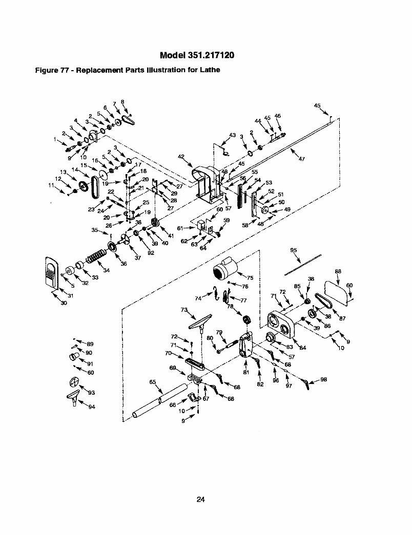
Model 351.217120
Figure 77 - Replacement Parts Illustration for Lathe
13.
11.
8
_89
94
,53
38
24

_K_:Y
I NO.
2
34
5
6
7
89
10
11
12
1314
1718
19i
21
23
24
25
L_
2728
32
i:135
41
42
PART NO.'18120.00
STD315555
18121.0018122.00
01900.0018123.00
i18124.oo[30256.0000483.00
STD852008
00341.00
181 25.00
18126.00
18127.00
15 18128.0016 18129.00
16453.0001097.00
i 18130.00i 181 31.00I
18132.00
18133.00181 34.00
18135.00181 36.00
00961.00
01760.0018137.00
181 38.0005479.00
181 39.00
181 40.0018141.00
18142.00
181 43.00181 44.00
20063.0001043.00
STD31 522506410.00
20064.0018147.00
I 43 18148.00
I 44 02472.00
DESCRIPTION QTY
Outboard Spindle I 1
6005zz Bal Bearing" ! 4; 3BMI-47 Retaining Ring ', 4
Spindle Seat I
3AMI-25 Retaining Ring 3OUtboard Spindle Pulley 1Drive Belt 1
3AMI-20 Retaining Ring 18-1.25 x 25ram Socket Head Bolt 8
8mm Lock Washer* 8
3AMI-17 Retaining Ring 1
Outboard Spindle Drive Pulley 1
Stationary Spindle Pulley 1
Variable Speed Bell I
Movable Spindle Pulley 151106 Beadng
6-1,0 x 40ram Socket Head Bolt6-1.0 x 35mm Socket Head Bolt
Pla_e
Plate 2
Spacer 4Unk 1
Nut (LH) 1
Adjusting Screw 1
Nut (RH) 16-1.0mm Hex Nut 5
6-1.0 x 16ram Socket Head Bolt 3
Adjusting Plate 1
Bushing 16-I.0 x 16ram Pan Head Scm,v 4
Headstock Cover 1
Cap 1
Spdng Retainer 1Spdng 1Pin 1
Movable Transmission Pulley 1
Stationary Transmission Pulley 16-1.0 x 8ram Set Screw 3
6202zz Bail Bearing* 28-1.25 x 16r_"n Socl=_ Head Bolt 3
Beating Support 1Headstock Body 1
Index Pin with Chain 1
5 x 5x 35ram Key 13
11
2
1
45 08335.00 5 x 5 x 18ram K_=y
46 181 49.00 Spindle
47 181 50.00 / Transmission Sbait
[ 48 i01784.00 I 5..O.8x lOmm Pan Head Screw
_4,9 [STD851005 _ 5mm Flat Wm&he('
* Standard hardware item available locally& Net Shown
rKEYNO. PART NO.50 18151.0051 01930.00
52 18152.0053 18153.00
54 18154.00
55 18155.00
56 18156.00
57 01282.0058 01874.00
59 16080.00
60 00389.00
61 18157.00
62 01680.00
63 18158,00
64 18060.0065 18159.00
66 18160.0067 18161.00
68 18162.00
69 18163,00
70 18164.0071 STD85100872 00732.00
73 18165.0074 18166.00
75 18167.00
76 18168.0077 00067.00
78 18169.0079 18170.00
80 9-25356
81 20059.00
82 18172.00
83 18173.0084 118174.00
85 18175,00
86 18176.0087 18177.00
88 18178.0089 18179.00
90 18180.0091 18181.00
92 08637.00
93 9-22554
94 18183.00
18193.0020057.00
20058.00
20060.00
18184.02
DESCRIPTIONKnob4-O.7 x 6mm Pan Heed Screw
' PointerRack CoverRackGuide
Bushing6-1.25 x 6ram Set Screw6-1,0 x 20mm Pan PleadScrew
Switch w_h Key5,0,8 x 12mm Pan Head ScrewSwitch BoxStrain ReliefSwitch Plate
5-0.8 x 10mmTap ScrewBed TubeAssemblyToolRest BracketPin
Locking Handle
ToolRest SupportToolRest Holder8mm FIstWasher'*8-1.25 x 30ram SockatHead Bolt
12" Tool RestMotorCordMotor
GrommetLine CordHandwheelQuill
#1M'FBearing CenterTailstockBodyLockingHandleCollar
Motor SupportMotor PulleyTransmissionShett PulleyV-beit
CoverCenter Cup Insert
Spur CenterCap
6006ZZ Ball Beadng4,"Faceplste6" Tool RestCenter Removal RodThreaded BushingBushingLockingHandleOperstoCsManual
QTY.I1I 1
11
k 11
122
1
7
1
11
31
1
1
3
11
4411111111111111
1!1
1
1
1
1
1
1
25
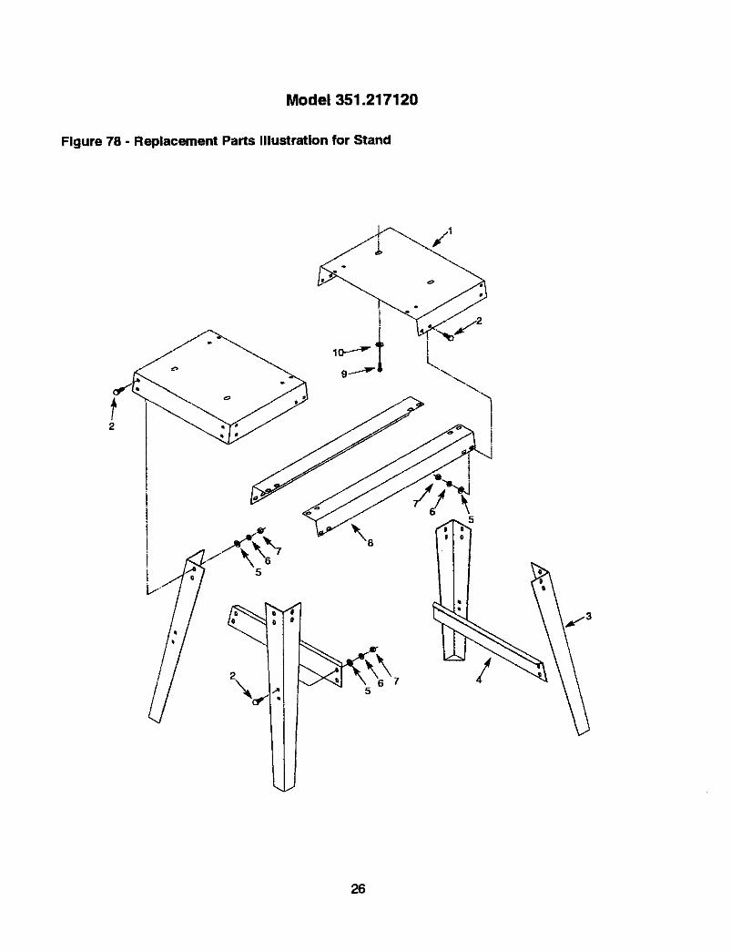
Model 351.217120
Figure 78 - Replacement Parts Illustrat|on for Stand
26

KEYNO. PART NO. DESCRIPTION QTY.
1 18185.00 Top T 2
2 STD533107 "/,o-18x °,_"Carriage Bolt* 40
3 18186.00 Leg 44 18187.00 Brace 25 STD551031 _A,"Flat Washer* 40
6 STD551131 'A," Lock Washer* 407 STD541031 ',_," Hex Nut* 40
8 18188.00 Support 29 06410.00 8-1.25 x 16mm Socket Head Bolt 4
10 STD851008 8ram Flat Washer* 4
A 18189,00 4" Outboard Faceptata& 18190.00 8" Outboard Faceplate
Standard hardware item available locally& Not Shown
RECOMMENDED ACCESSORIES
i A-TM'I'I WorkArbor withJaccbs Chuck
A M'I'I WorkArborwithFlangesA MT1 60 ° Bearing Center
A MT1 Spur Center_. MT! 60= Center
A MTt Screw Center
_. MT1 TallstockCup CenterA 4" Face Plate, t"-8 TPI
/, 8" Face Plate, 1"-8 TPI
/, 6'/z"x 4-Jaw Chuck, t"-STPI
,_ Center Finder
& RQbertSofoyTurningTools (6 pc. set)
Accessoriesavailable in catalog and largerretail st(ca,s.
9-25354
9-25355
925356
9-25357
9-25358
9-25359
9-25360
9-298409-29841
9-29842
9-25372
9-2983O
27

Your Home
For repair-in your home-of all major brand appliances,lawn and garden equipment, or heating and cooling systems,
no matter who made it, no matter who sold it!
For the replacement parts, accessories andowner's manuals that you need to do-it-yourself
!
For Sears professional installation of home appliancesand items like garage door openers and water heaters
1-800-4-MY-HOME ® (1-800-469-4663)Call anytime, day or night (U.S.A. and Canada)
www.seam.com www.sears.ca
Our HomeFor repair of carry-in items like vacuums, lawn equipment,
and electronics, call or go on-line for the location of your nearestSears Parts & Repair Center.
1-800-488-1222Call anytime, day or night (U SA only)
www.seQrs.com
To purchase a pmtecl_onagreement on a product serviced by Seam:
1-800-827-6655 (u.s.A.) 1-800-361-6665 (Canada)
Para pedir servicio de reparaci0na domicilio, y para ordenar piezas:
1-888-SU-HOGAR _
Au Canada pour service en frangais:
1-800-LE-FOYEFP c
(1-eoo-533-6937)(1-888-784-6427) www .sears .ca
sm 8® Regtsteced Trsdema#, / ra Trademmk / aMSOP'i= Miuk Cf Seam, Roebuck and Co.® M area Regist rada / TMMsrca de Fr4bdca / su Mares de 5ent;cio de Sears, _ck md _
MCMarque de cornmeme / MDM arqJe ddpo,s_e de Sem_ Roebuck md Co. @ Seam, Roebuck end Co