operator’s manual - land pride · 7 introduction 7/14/08 rc45180 & rcm45180 rotary cutter...
TRANSCRIPT
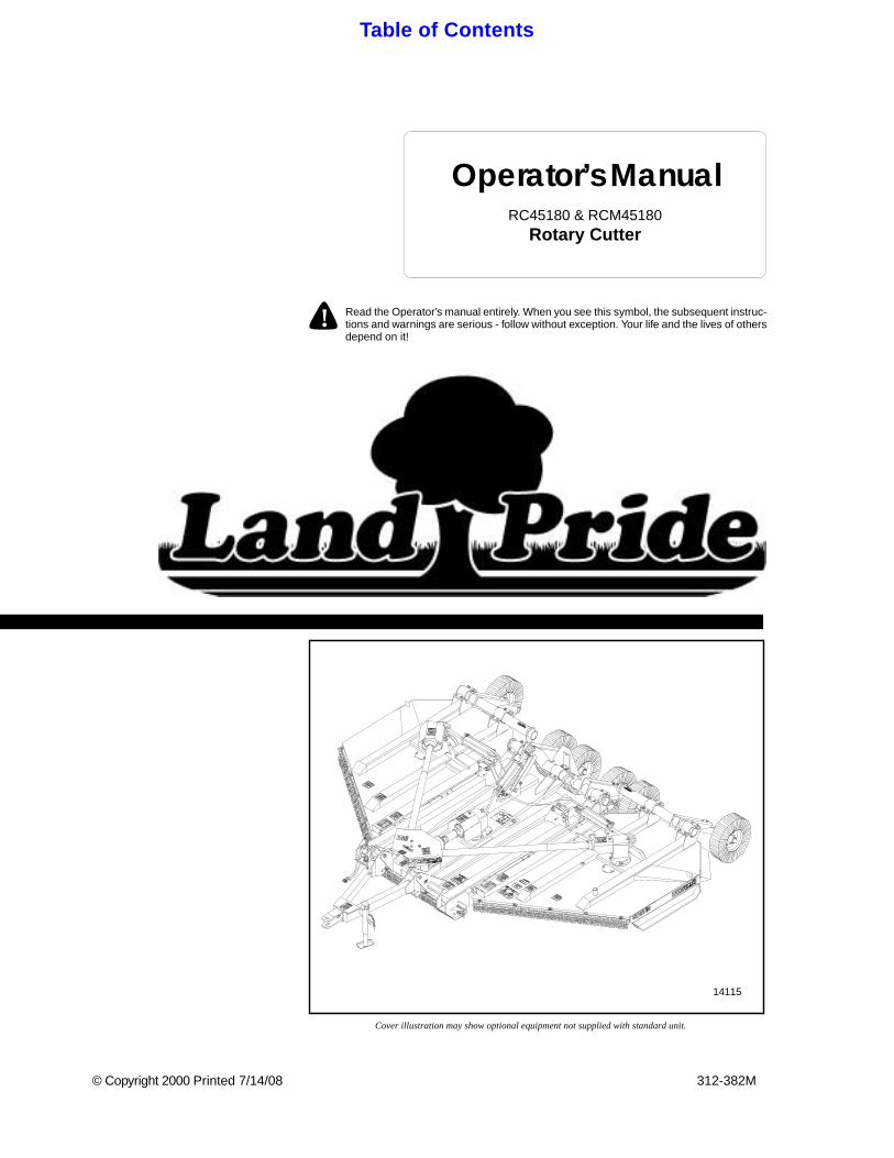
Cover illustration may show optional equipment not supplied with standard unit.
© Copyright 2000 Printed 7/14/08
Operator’s Manual
! Read the Operator’s manual entirely. When you see this symbol, the subsequent instruc-tions and warnings are serious - follow without exception. Your life and the lives of othersdepend on it!
Table of Contents
312-382M
RC45180 & RCM45180Rotary Cutter
14115
Table of Contents
Land Pride
Table of Contents
Important Safety Information . . . . . . . . . . .1Safety Notations . . . . . . . . . . . . . . . . . . . . . . . . . . 1Safety Rules . . . . . . . . . . . . . . . . . . . . . . . . . . . . . 1
General . . . . . . . . . . . . . . . . . . . . . . . . . . . . . . . 2Transporting . . . . . . . . . . . . . . . . . . . . . . . . . . . 2Tire Handling & Repair . . . . . . . . . . . . . . . . . . . 2
Safety Labels . . . . . . . . . . . . . . . . . . . . . . . . . . . . . 3
Introduction . . . . . . . . . . . . . . . . . . . . . . . .7Using This Manual . . . . . . . . . . . . . . . . . . . . . . . . . 7
Terminology: . . . . . . . . . . . . . . . . . . . . . . . . . . . 7Definitions: . . . . . . . . . . . . . . . . . . . . . . . . . . . . 7
Owner Assistance . . . . . . . . . . . . . . . . . . . . . . . . . 7Serial Number Plate . . . . . . . . . . . . . . . . . . . . . 7
Section 1 Assembly and Setup . . . . . . . . .8Tractor Requirements . . . . . . . . . . . . . . . . . . . . . . 8Before You Start . . . . . . . . . . . . . . . . . . . . . . . . . . 8Dealer Cutter Assembly & Preparations . . . . . . . . 8Left & Right Wing Axle Assembly . . . . . . . . . . . . . . 8Hitch Assembly . . . . . . . . . . . . . . . . . . . . . . . . . . . 8Slow Moving VehicleBundle Assembly . . . . . . . . . . . . . . . . . . . . . . . . . . 9Hydraulic Plumbing . . . . . . . . . . . . . . . . . . . . . . . . 9Tractor Hookup . . . . . . . . . . . . . . . . . . . . . . . . . . 10
Section 2 Operating Instructions . . . . . .12Operating Check List . . . . . . . . . . . . . . . . . . . . . . 12Transporting . . . . . . . . . . . . . . . . . . . . . . . . . . . . 13Parking . . . . . . . . . . . . . . . . . . . . . . . . . . . . . . . . 13
Section 3 Adjustments . . . . . . . . . . . . . . .14Center Deck Level Adjustments . . . . . . . . . . . . . . 14Center Deck Rear Axle Arms Adjustment . . . . . . 14Wing Deck Level Adjustments . . . . . . . . . . . . . . . 15Wing Deck Tailwheel Rubber Bumper Adjustment 15
RC45180 & RCM45180 Rotary Cutter 312-382M
© Copyright 2008 All rights Reserved
Land Pride provides this publication “as is” without warranty of any kind, either expressedPride assumes no responsibility for errors or omissions. Neither is any liability assumed forthe right to revise and improve its products as it sees fit. This publication describes the stat
Land Pride is a reg
All other brands and product names are trademarks
Printed in the United
Section 4 Troubleshooting . . . . . . . . . . .16
Section 5 Maintenance and Lubrication .17Maintenance . . . . . . . . . . . . . . . . . . . . . . . . . . . . 17Service Cutting Blades . . . . . . . . . . . . . . . . . . . . . 17Skid Shoes . . . . . . . . . . . . . . . . . . . . . . . . . . . . . . 17Clutch Run-In . . . . . . . . . . . . . . . . . . . . . . . . . . . . 18Storage . . . . . . . . . . . . . . . . . . . . . . . . . . . . . . . . 18Lubrication . . . . . . . . . . . . . . . . . . . . . . . . . . . . . . 19
Axle Hub Bearing . . . . . . . . . . . . . . . . . . . . . . 19Wing Hinges (6) . . . . . . . . . . . . . . . . . . . . . . . . 19Ratchet Jack . . . . . . . . . . . . . . . . . . . . . . . . . . 19Axle Rockshaft & Axle Link . . . . . . . . . . . . . . . 20Main Hitch . . . . . . . . . . . . . . . . . . . . . . . . . . . . 20Gearbox . . . . . . . . . . . . . . . . . . . . . . . . . . . . . 20Divider Box . . . . . . . . . . . . . . . . . . . . . . . . . . . 20Driveline Shaft . . . . . . . . . . . . . . . . . . . . . . . . . 21Drive line Shafts . . . . . . . . . . . . . . . . . . . . . . . 21PTO Constant Velocity Shaft . . . . . . . . . . . . . .21
4-Plate Slip Clutch . . . . . . . . . . . . . . . . . . . . . . . . 22Disassembly . . . . . . . . . . . . . . . . . . . . . . . . . . . . . 22Assembly . . . . . . . . . . . . . . . . . . . . . . . . . . . . . . . 22
Section 6 Specifications and Capacities 23
Section 7 Appendix . . . . . . . . . . . . . . . . .24Tire Inflation Chart . . . . . . . . . . . . . . . . . . . . . . . . 24Torque Values Chart for Common Bolt Sizes . . . .24Warranty . . . . . . . . . . . . . . . . . . . . . . . . . . . . . . . 25
7/14/08
or implied. While every precaution has been taken in the preparation of this manual, Landdamages resulting from the use of the information contained herein. Land Pride reserves
e of this product at the time of its publication, and may not reflect the product in the future.
istered trademark.
or registered trademarks of their respective holders.
States of America.
Important Safety Information
Land Pride Table of Contents
Important Safety Information
For your safety and to develop a better understanding ofyour equipment, thoroughly read the Operator’s Sectionsof this manual before operation.
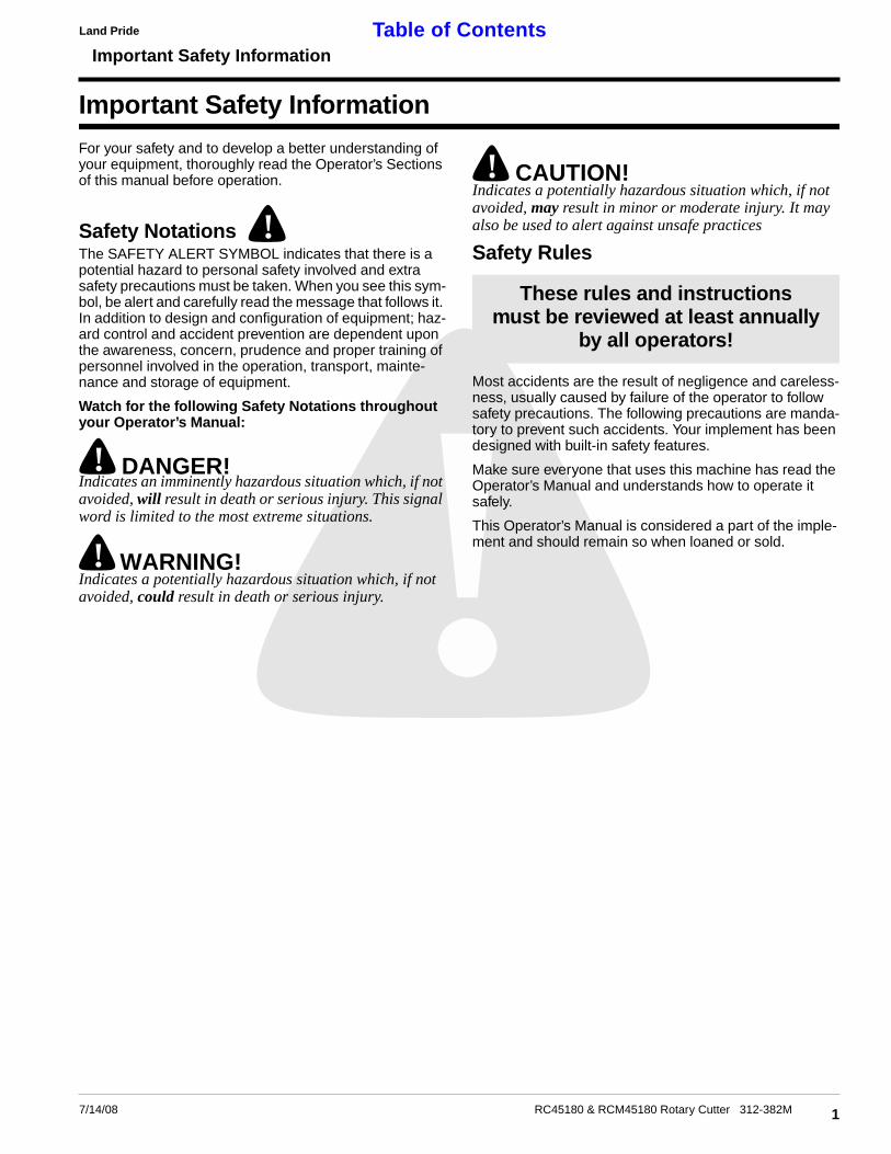
Safety NotationsThe SAFETY ALERT SYMBOL indicates that there is apotential hazard to personal safety involved and extrasafety precautions must be taken. When you see this sym-bol, be alert and carefully read the message that follows it.In addition to design and configuration of equipment; haz-ard control and accident prevention are dependent uponthe awareness, concern, prudence and proper training ofpersonnel involved in the operation, transport, mainte-nance and storage of equipment.
Watch for the following Safety Notations throughoutyour Operator’s Manual:
! DANGER!Indicates an imminently hazardous situation which, if notavoided, will result in death or serious injury. This signalword is limited to the most extreme situations.
! WARNING!Indicates a potentially hazardous situation which, if notavoided, could result in death or serious injury.
!
7/14/08
!
! CAUTION!Indicates a potentially hazardous situation which, if notavoided, may result in minor or moderate injury. It mayalso be used to alert against unsafe practices
Safety Rules
Most accidents are the result of negligence and careless-ness, usually caused by failure of the operator to followsafety precautions. The following precautions are manda-tory to prevent such accidents. Your implement has beendesigned with built-in safety features.
Make sure everyone that uses this machine has read theOperator’s Manual and understands how to operate itsafely.
This Operator’s Manual is considered a part of the imple-ment and should remain so when loaned or sold.
These rules and instructionsmust be reviewed at least annually
by all operators!
1RC45180 & RCM45180 Rotary Cutter 312-382M

Important Safety Information
Land PrideTable of Contents
General1. Do not allow anyone to operate this machine who has not
been properly trained in its safe operation.2. To prevent personal injury caused by thrown objects, the
use of front and rear safety shields is strongly recommend-ed.
3. Do not let children operate the cutter.4. Never allow passengers.5. Never operate the cutter near people and do not stand near
the cutter while blades are in motion.6. Before cutting, clear the area of objects and debris that
could become entangled in the blades or thrown from thecutter.
7. After striking an object, disengage PTO, shut off tractorand inspect for damage before continuing.
8. Do not operate the cutter in reverse unless necessary. De-bris may be thrown from the front of the cutter; therefore,increasing the risk of injury to the operator.
9. Check the cutter periodically for loose hardware and tight-en if necessary.
10. Travel slowly over rough terrain and be alert to holes andgullies.
11. When traveling on public roads, use accessory lights anddevices for adequate warning to operators of other vehi-cles. Comply with all Federal, State, and Local laws.
12. Never operate the cutter while in the raised transport posi-tion.
13. Be alert to traffic when crossing or cutting near roadways.14. Disengage the PTO when raised for transport or backing
up.15. Wear proper eye protection to prevent injury from flying
objects.16. Keep PTO shielding in place and in good condition. do not
operate cutter with shields missing.17. Always use proper PTO speed or machine damage may re-
sult. This cutter is designed to be used with a tractor usinga 540 or 1,000 rpm rear PTO. Important: Never shoulda machine equipped for 540 rpm PTO be operated by atractor equipped with a 1,000 rpm PTO nor should a 1,000rpm PTO machine be operated with a tractor equippedwith a 540 rpm PTO.
18. In order to maintain steering control, add ballast to trac-tor. To determine the amount of ballast required refer toyour tractor operator’s manual.
19. Before performing maintenance, disconnect PTO drivelineand hydraulic hoses and securely block cutter on safe sup-porting stands. Do not position stands under axle or wheelsupports.
20. Transport cutter with transport axle lock pin installed andwing lock latches in place.
21. Escaping hydraulic fluid under pressure can have suffi-cient force to penetrate the skin. Check all hydraulic hosesbefore applying pressure. Fluid escaping from a verysmall hole can be almost invisible. Use paper or card-board, not body parts, to check for suspected leaks. If in-jured, seek medical assistance from a doctor that isfamiliar with this type of injury. Foreign fluids in the tissuemust be surgically removed within a few hours or gangrenewill result.
2 RC45180 & RCM45180 Rotary Cutter 312-382M
22. Do not permit anyone to stand between tractor and cutter- especially during tractor hook-up.
23. Purge air from hydraulic system before attempting to raiseor lower wings.
24. Stand clear of wings when raising or lowering.
Transporting1. Be alert to traffic when crossing or operating near road-
ways. Always maintain complete control of the machine.Know your state and local laws concerning highway safetyand regulations. Comply with these laws when transportingmachinery.
2. Do not exceed 15 mph when trasnporting. Transport onlywith a farm tractor of sufficient size and horse power. See“Tractor Requirements” Section 1, PAGE 8.
3. Always make sure flashing safety lights, slow moving vehi-cle emblem, and reflectors are in place and visible prior totransporting the machine on public roads, when required.
4. Do not transport at night or during other periods of poorvisibility.
Tire Handling & Repair1. Tire changing can be dangerous and should be preformed
by trained personnel using the correct tools and equip-ment.
2. Do not re-inflate a tire that has been run flat or seriouslyunder inflated. Have it checked by qualified personnel.
3. When removing and installing wheels, use wheel handlingequipment adequate for the weight involved.
7/14/08
Important Safety Information
Land Pride Table of Contents
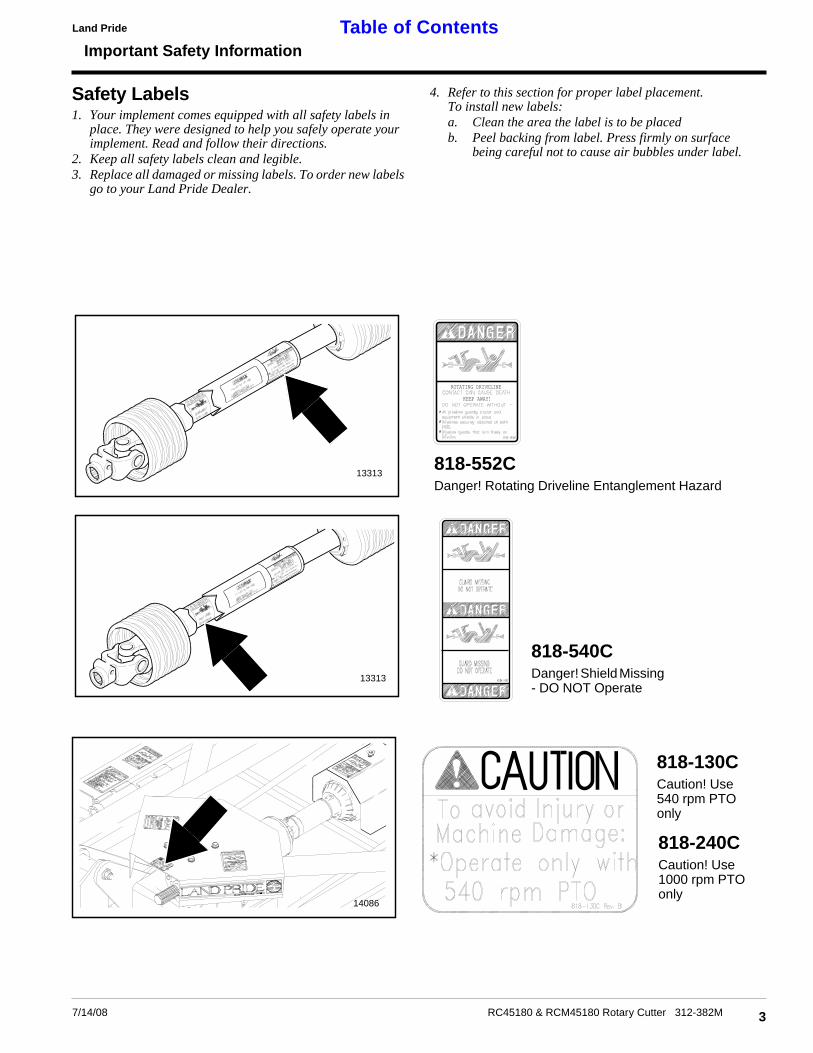
Safety Labels1. Your implement comes equipped with all safety labels in
place. They were designed to help you safely operate yourimplement. Read and follow their directions.
2. Keep all safety labels clean and legible.3. Replace all damaged or missing labels. To order new labels
go to your Land Pride Dealer.
4. Refer to this section for proper label placement.To install new labels:a. Clean the area the label is to be placedb. Peel backing from label. Press firmly on surface
being careful not to cause air bubbles under label.
37/14/08 RC45180 & RCM45180 Rotary Cutter 312-382M
818-552CDanger! Rotating Driveline Entanglement Hazard
818-130CCaution! Use540 rpm PTOonly
818-540CDanger! Shield Missing- DO NOT Operate
ROTATING DRIVELINE
KEEP AWAY!
14086
13313
13313
818-240CCaution! Use1000 rpm PTOonly
4
Important Safety Information
RC45180 & RCM45180 Rotary Cutter 312-382M 7/14/08
Land PrideTable of Contents
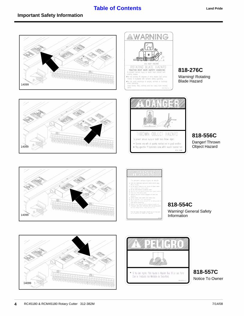
818-276CWarning! RotatingBlade Hazard
14099
TRACTOR MUST HAVE SAFETY GUARDING
818-556CDanger! ThrownObject Hazard
818-554CWarning! General SafetyInformation
14099
14099
14099
818-557CNotice To Owner
5
Important Safety Information
7/14/08 RC45180 & RCM45180 Rotary Cutter 312-382M
Land Pride Table of Contents
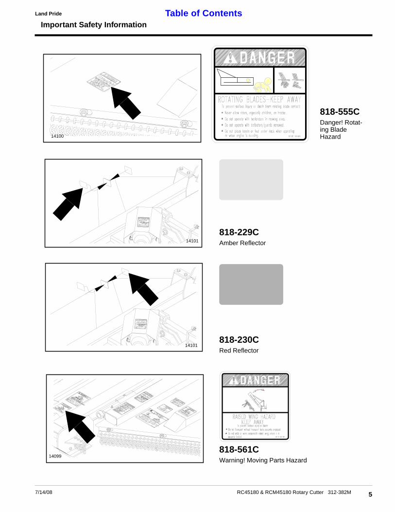
818-555CDanger! Rotat-ing BladeHazard14100
818-230CRed Reflector
14101
14101
818-561CWarning! Moving Parts Hazard
14099
818-229CAmber Reflector

6
Important Safety Information
RC45180 & RCM45180 Rotary Cutter 312-382M 7/14/08
Land PrideTable of Contents
14099
818-440CCaution! Wing latches & transport link information.
14099
818-559CNotice To Owner
14086
818-240CCaution! Use1000 rpm PTOonly

Introduction
Land Pride Table of Contents
Introduction
Using This ManualThis Operator’s Section is designed to help familiarize youwith safety, assembly, operation, adjustments, trouble-shooting, and maintenance. Read this manual and followthe recommendations to help ensure safe and efficientoperation.
The warranty sheet should be filled out by the owner anddealer at the time of purchase. After completion give thedealer the white copy and send the pink copy to GreatPlains. Keep your copy in the manual for use when corre-sponding with the dealer.
To order a new Operator or Parts Manual contact your au-thorized dealer or write to the address listed below in the"Owner Assistance" paragraph. Include the model and se-rial numbers of your unit.
The information contained within this manual was currentat the time of printing. Some parts may change slightly toassure you of the best performance.
Terminology:"Right " or "Left" as used in this manual is determined byfacing the direction the machine will travel while in use un-less otherwise stated.
Definitions:
IMPORTANT: Information, related to it’s proceeding topic,that the author feels would be of use.
Owner AssistanceIf customer service or repair parts are required contactyour local Land Pride Dealer. He has trained personnel,repair parts, and the equipment needed to service yourimplement.
These parts have been specially designed and shouldonly be replaced with genuine Land Pride parts.
NOTE: A special point of information related to it’spreceding topic. The author’s intention is that youread and note this information before continuing.
7/14/08
Serial Number PlateRefer to the following illustration for the location of your se-rial number plate.
For prompt service always use the serial number and modelnumber when ordering parts from your Land Pride Dealer.Be sure to include your serial and model numbers in corre-spondence also.
Your dealer wants you to be satisfied with your new ma-chine. If for any reason you are not satisfied with the ser-vice received, the following actions are suggested:
1. Discuss the matter with your dealership Service Man-ager make sure he is aware of any problems you mayhave and that he has had the opportunity to assistyou.
2. If you are still not satisfied, seek out the Owner orGeneral Manager of the dealership, explain the prob-lem and request assistance.
3. For further assistance write to:
Customer Service
Great Plains Mfg. Inc.
P.O. Box 245
Assaria, Ks. 67416
Serial Number Plate LocationFigure 1
14183
7RC45180 & RCM45180 Rotary Cutter 312-382M

Section 1 Assembly and Setup
Land PrideTable of Contents
Section 1 Assembly and Setup
Tractor RequirementsThis cutter is designed for tractors with a minimum PTOhorsepower rating of 50 HP and maximum of 150 HP.
! CAUTION!Do not over speed PTO or machine damage may result. Thiscutter is designed to be used with a tractor using a 540 or1,000 rpm rear PTO but not both.
Specifically, each cutter is equipped for only one mode ofoperation. Do not attempt to operate a 540 PTO cutterwith a 1,000 RPM PTO tractor. Do not operate a 1000RPM PTO cutter with a 540 PTO tractor. Note that manytractors provide both 540 and 1,000 RPM PTO modes.Check your tractors manual to determine your exact con-figuration.
Before You StartRead and understand the owners manual for your cutter. Abasic understanding of how it works will aid in the assem-bly and setup of your cutter.
Before attempting to assemble the cutter use the followingas a check list. Having all the needed parts and equipmentreadily at hand will speed up your assembly task and willmake the job as safe as possible.
❑ Check for fasteners and pins that were shipped with thecutter. Note: All hardware coming from the factory hasbeen installed in the location where it will be used. If a partor fastener is temporarily removed for assembly reasons,remember where it goes. Keep the parts separated.
❑ If a pin, bolt or other part has been removed, and youare unsure where it is used, use the parts section to iden-tify it. Be sure the part gets used in the correct location. Bydouble checking while you assemble, you will decreasethe chance of using a bolt incorrectly that may be neededlater.
❑ Have a fork lift or loader along with chains and safetystands that are sized for the job ready for the assemblytask.
❑ Have a minimum of 2 people at hand while assemblingthe cutter.
❑ Check to see all nuts are tightened. See “Torque Val-ues Chart” page 24 for additional torque specifications.
Dealer CutterAssembly & PreparationsThis cutter has been partially assembled at the factory.The hitch & both wing axles will need to be assembled.
Left & Right Wing Axle Assembly
Refer to Figure 1-1:1. Assemble axle tube arm assembly (#1) with tire to
wing axle (#2), using axle mount pin (#3) with hard-ware. Install rubber bumpers (#4) with hardware.
2. Grease points marked by arrows as noted in "Maintenance & Lubrication" section page 19.
Hitch AssemblyRefer to Figure 1-2:
1. Insert main hitch rear mount bushings (#2) into hitchpivot. Install the main hitch (#1) to the forward hitchplates. Secure with 1" x 8" hex bolt (#3) and 1" flatwashers and Nylock nut. Nut should be located to-ward the inside as shown.
2. Install both leveling rods (#4) through the respectivetrunnion pivot of the hitch. Secure the leveling rod tothe hitch with the leveling tube weldment (#6) and a 7/8" hex nut (#8). Note: The leveling tube weldmentshould be screwed onto the leveling rod about 3" as apreliminary adjustment. Final adjustment should notbe made until the cutter is attached to the tractor.
NOTE: Hardware bag should be banded to unit.
NOTE: Make sure nuts & bolts are tight.
Wing Axle AssemblyFigure 1-1
13869
NOTE: Do not tighten hardware until assembly iscomplete.
8 RC45180 & RCM45180 Rotary Cutter 312-382M 7/14/08

Section 1 Assembly and Setup
Land Pride Table of Contents
3. Install screw jack (#7) to hitch and secure with at-tached pin. Adjust jack until center deck is approxi-mately horizontal.
Slow Moving VehicleBundle AssemblyRefer to Figure 1-3:Install bracket (#1) with hardware shown to bearing cap.Then install Slow Moving Vehicle (#2) to bracket (#1) byusing screw 1/4" x 5/8" Long (#3) with square nut (#5) andlock washer (#4).
Hydraulic PlumbingRefer to Figure 1-4:The standard cutter is equipped with hydraulic cylindersfor each wing to provide simultaneous folding.
An optional hydraulic lift adjustment kit is also availablefrom your Dealer.
11153
Hitch Assembly IllustrationFigure 1-2
Slow Moving Vehicle AssemblyFigure 1-3
13895
97/14/08 RC45180 & RCM45180 Rotary Cutter 312-382M
Hydraulic PlumbingFigure 1-4
14102

Section 1 Assembly and Setup
Land PrideTable of Contents
Your Dealer will be able to help you determine the bestconfiguration to match your tractor.
Tractor HookupRefer to Figure 1-5:1. Back the tractor up to the tongue until holes in draw-
bar and cutter hitch are aligned. Raise or lower tonguejack to correct height.
2. Attach cutter with 1" hitch pin and secure with lock pin.Always use a pin that contains a safety locking deviceto prevent it from falling out.
3. Lower tongue jack until weight of cutter is fully re-moved from jack, then remove the jack. Store the jackon the left hand wing deck. A storage base is locatednear the front edge of the wing.
4. Attach safety chain on tongue hitch to tractor. Adjustchain length to remove all slack except what is neces-sary to permit turning of the cutter. Lock hook securelyon chain.
Refer to Figure 1-6:5. The PTO shaft from the tractor may be a constant ve-
locity type or conventional. Attach the 1 3/4-20 splinedend to the input side of the power divider gearbox. At-tach end with the quick disconnect to the tractor.
NOTE: Each pair of outlets on your tractor can onlyoperate one remote cylinder. All three cylinders onthe cutter are single action (one-way) type cylindersand should not be plumbed for two-way operation.
10 RC45180 & RCM45180 Rotary Cutter 312-382M
14103
6. Secure chain on PTO around cutter tongue to restrictouter shield of PTO from rotating.
7. PTO should now be moved back and forth to insurethat it is secured on the shaft of the tractor and powerdivider input shaft on the cutter.
8. Should the PTO shaft require shortening:
a. Hold the half shafts next to each other in the short-est working position and mark them.
PTO Quick DisconnectFigure 1-6
11150
NOTE: The PTO quick disconnect consists of agraphite reinforced, round sleeve that must be rotat-ed about it's own axis to engage/disengage the shaft.
NOTE: Two small chains are supplied with eachPTO. These chains must be attached to the outershields of each PTO shield and to an anchor ring onthe cutter deck or hitch
7/14/08
Tractor Hook-UpFigure 1-5
Section 1 Assembly and Setup
Land Pride Table of Contents
b. Shorten inner and outer guard tubes equally.
c. Shorten inner and outer sliding profiles by thesame length as the guard tubes.
d. Proper overlap is a minimum of one-half thelength of each tube, with both tubes being of equallength.
e. Round off all sharp edges and remove burrs.Grease sliding profiles.
9. Route cylinder hoses through hose support loop andconnect to tractor remote outlets. Refer to "HydraulicPlumbing" on page 9 for proper hookup. If the tractorbeing used does not have three pair of supply outlets,an optional control valve kit is available from yourdealer.
10. Cycle the hydraulic system by raising and lowering thecenter deck cylinder and the wing fold cylinders. If op-eration is sluggish, it may be necessary to purge thesystem of trapped air.
! DANGER!Hydraulic fluid under pressure can penetrate skin. Wear protec-tive gloves and safety glasses or goggles when working with hy-draulic systems. Use a piece of cardboard or wood rather thanhands when searching for hydraulic leaks. If hydraulic fluid isinjected into the skin, it must be surgically removed within a fewhours by a doctor or gangrene may result.
7/14/08
a. With the wings lowered to the ground, loosen thehydraulic hose fitting at each wing cylinder slightlyto allow fluid to escape.
b. Slowly activate the tractor control valve to purgeany trapped air from the system.
c. Tighten each fitting.
The optional center deck lift cylinder is purged in the samemanner. The cutter should be lowered to the ground or thecylinder fully retracted before loosening the hose fitting (asdescribed above).
11. The PTO Constant Velocity shaft or conventional PTO(if used) should be checked for adequate clearanceunder all ranges of cutter height depending on thetractor being used. With the PTO shaft attached to thetractor, slowly raise and lower the cutter to upper andlower limits while observing clearance distance be-tween hitch and PTO shaft. If an interference condi-tion exists, it may be necessary to modify the drawbarheight/length of the tractor.
11RC45180 & RCM45180 Rotary Cutter 312-382M

Section 2 Operating Instructions
Land PrideTable of Contents
Section 2 Operating Instructions
Operating Check ListIn addition to design and configuration of equipment; haz-ard control and accident prevention are dependent uponthe awareness, concern, prudence and proper training in-volved in its operation, transport, maintenance and stor-age of equipment. Before beginning to operate yourCutter, the following inspection should be performed.
! WARNING!The following operating procedures should be carried out bythe tractor operator. Other persons should be cleared of thearea even during cutter setup. cutter operation should bestopped when in the vicinity of other persons.
Refer to Figure 2-1:1. Raise the center deck to sufficient height to disengage
the transport link (#1) . Remove the transport link pin(#2), lower the link arm, then replace the link pin to thestorage position.
2. Inspect the wing blade carriers and blades prior tolowering the wings. The wing deck blades may be-come locked together (overlapped) when the wingsare raised to transport position. Operating the cutterunder such circumstances will result in severe deck vi-bration. Inspect the wing decks for a locked blade con-dition prior to power-on operation. Use a pry bar orother tool to separate the blades if necessary.
3. The automatic wing latches on each wing must be re-leased prior to lowering the wings. If the wing latchhandles cannot be moved, it may be necessary toraise the wings to the fully closed position. Releasewing latch and then lower the wings to full-down posi-tion.
Check ReferenceRead and follow the “Safety Rules” care-fully.
Section 1page 1
Read all of the "Tractor Hook Up" and prep-aration instructions.
Section 1page 10
“Operating Instructions” in this Manual Section 2page 12
Lubricate the cutter as needed. Refer to"Lubrication"
Section 5page 19
Check the cutter initially and periodically forloose bolts & pins, "Torque Values Chart".
Section 6page 24
Make sure all guards and shields are inplace.
Section 1page 3
Gearbox Gear Lube Section 5page 20
NOTE: The center deck height is controlled with thestandard ratchet jack or the optional hydraulic lift cyl-inder.
12 RC45180 & RCM45180 Rotary Cutter 312-382M
4. Increase throttle to approximately 500 RPM and slow-ly engage PTO. Ensure that all power shafts are rotat-ing and that cutter has no vibration.
5. Continue to increase throttle to full PTO speed beforecommencing forward operation.
Refer to Figure 2-2:Optimum Ground speed depends on the density of thematerial being cut, the horsepower rating of the tractor,and (in some cases) terrain.
If the cutter-to-tractor PTO is a standard conventionalshaft, avoid tractor-to-cutter turning angles exceeding 35˚.If equipped with a Constant Velocity PTO shaft, the turn-ing angle may be increased to 80˚. These extreme anglesare intended for intermittent usage only and not prolongusage. Plan your field cutting to minimize the number ofturns as well as the extreme angles where turns arenecessary.
Transport LinkFigure 2-1
13885
Conventional U-Joint PTOFigure 2-2
11934
7/14/08

Section 2 Operating Instructions
Land Pride Table of Contents
This cutter was designed to cut grass and medium toheavy brush in pastures, right-of-ways, and certain ditch/terrace areas. This cutter is also useful for heavy row cropcutting. Avoid areas where small trees or brush diametersexceed 2". Do not attempt to operate this cutter in areaswhere rocks, steel, glass, concrete, wire, or other hard,foreign objects may be present.
! WARNING!Do not operate this cutter under any terrain conditions wherethe wing angle exceeds 45˚ up. Ensure that the wing wheels arein continuous ground contact at all times. Use the float positionof your tractors hydraulic system to provide automatic wingfloat position for varying terrain conditions.
Transporting
! DANGER!Rotary Cutters have the ability to discharge objects at highspeeds; do not operate this cutter along highways, roadways orother areas where people may be present unless approvedguarding has been installed and properly maintained. Factoryapproved guarding includes front and rear safety chain, deflec-tor skirts or other shields. Contact your dealer or call GreatPlains Manufacturing, Inc. for the name of your nearest factoryauthorized dealer.
! CAUTION!When traveling on public roads whether at night or during theday, use accessory light and devices for adequate warning tooperators of other vehicles. Comply with all federal, state andlocal laws.
! CAUTION!Always disengage tractor PTO before transporting cutter toavoid injury from thrown objects or blade contact.
1. Select a safe ground travel speed when transportingfrom one area to another. When traveling on road-ways, transport in such a way that faster moving vehi-cles may pass you safely.
2. Reduce tractor ground speed when turning. Leaveenough clearance so the cutter does not contact ob-stacles such as buildings, trees or fences.
3. When traveling over rough or hilly terrain, shift tractorto a lower gear.
4. Raise cutter to transport position using the hydrauliclift or rachet jack. Careful: When raising to transportposition, be certain that PTO shaft does not contacttractor or cutter tongue.
5. Raise both wings to 85˚ vertical position. The auto-matic wing latches should engage. Check to be surethey are fully latched.
Refer to Figure 2-3:6. Engage transport lock (#1) by removing lock pin (#2)
and rotating transport lock to 45˚ position. Insert lockpin through detent notch and secure with hair pin cot-ter (#3).
7. Slowly lower the cutter until transport lug of axle weld-ment contacts transport lock block.
8. Reduce tractor ground speed when turning; be suretractor wheel does not contact cutter when turning.Leave clearance so cutter does not contact obstaclessuch as buildings, trees or fences.
9. The cutter should be transported no faster than 15mph when equipped with laminated or solid tires,and 30 mph when equipped with pneumatic tires.
! CAUTION!The cutter is 8’ 9" wide and care should be taken when encoun-tering oncoming traffic and roadside obstructions.
ParkingThe following steps should be done when preparing tostore the cutter or unhitch it from the tractor. See also“Storage”, on page 18 for additional information on longterm storage of your cutter.
1. Park the cutter on a level, solid area.
2. Shut off tractor engine and engage parking brake.
3. Install jack & crank up the jack until it is supporting theunit.
4. Unhitch from tractor.
Transport Link OperationFigure 2-3
13885
137/14/08 RC45180 & RCM45180 Rotary Cutter 312-382M

Section 3 Adjustments
Land PrideTable of Contents
Section 3 Adjustments
Center Deck Level AdjustmentsThese adjustments should be made with the cutterhooked up to the same tractor that will be used for field op-erations or one having the same drawbar height.
! CAUTION!Engage parking brake, shut off tractor, remove key and disen-gage PTO before making any height adjustments!
Center Deck Rear AxleArms Bolt & Nut Adjustment
Refer to Figure 3-1:1. Tighten all four bolts (#1) until the nuts (#2) bottom out
on the bolts (this is to loosen springs up) then loosenall 4-bolts until all the nuts are loose.
2. Measure the distance "A" on both center axle armtubes to axle channel.
3. On the side with the shortest "A" Measurement, tight-en nuts up until they are just snug against the axletube!
4. Adjust the other axle assembly (with the longest "A"measurement), by tightening the nuts (#2), until it’s "A"measurement is the same as the previous axle as-sembly (with the shortest "A" measurement).
Refer to Figure 3-2:With the cutter positioned on level ground, the deck shouldbe adjusted to a level position for the drawbar height of thetractor being used.
1. Raise both wings to latched position. Adjust the heightof the center deck to 2-3 inch clearance between thefront skids and ground surface.
2. Place a level anywhere on a center deck channel. Itshould be oriented for front-to-rear readings.
3. Loosen hex nut (#1) on level rod and turn the levelingtube weldment (#2) clockwise to raise the front of the
NOTE: Cutter is to be set up on level ground with thewings folded up and in the locked position.
13134Center Deck Rear AxleFigure 3-1
14 RC45180 & RCM45180 Rotary Cutter 312-382M 7/14/08
14104 Center Deck Level AdjustmentsFigure 3-2
Section 3 Adjustments
Land Pride Table of Contents
cutter or counterclockwise to lower. Continue to adjustuntil the deck is level or the front is slightly below level.Both leveling rods should be adjusted to equallengths.
4. Tighten jam nut (#1) to secure leveling rods.
5. This setting should not require further adjustment un-less the drawbar height is changed or different sizetires are used.
6. The cutting height can be adjusted by extending or re-tracting the hydraulic cylinder or rachet jack locatedat the rear center of the cutter.
Wing Deck Level Adjustments
IMPORTANT: Ensure that Center Deck Level Adjustmentshave been made before proceeding with wing deck leveladjustments.
! CAUTION!Engage parking brake, shut off tractor, remove key and disen-gage PTO before making any height adjustments!
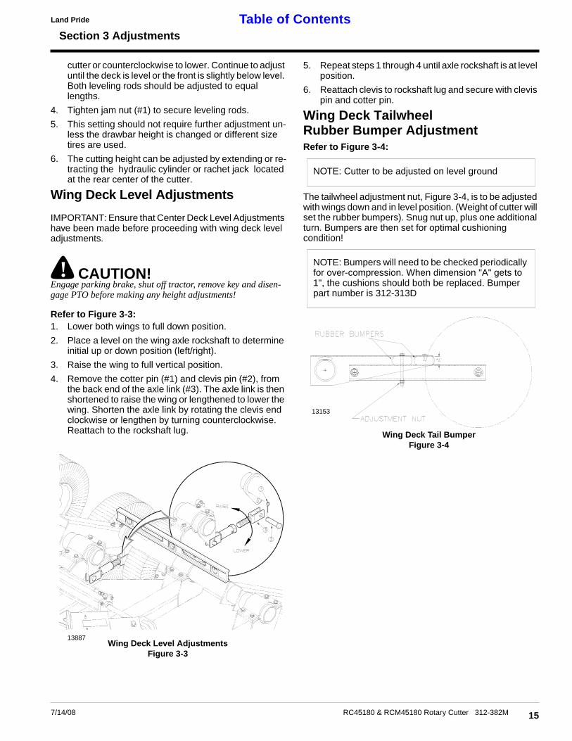
Refer to Figure 3-3:1. Lower both wings to full down position.
2. Place a level on the wing axle rockshaft to determineinitial up or down position (left/right).
3. Raise the wing to full vertical position.
4. Remove the cotter pin (#1) and clevis pin (#2), fromthe back end of the axle link (#3). The axle link is thenshortened to raise the wing or lengthened to lower thewing. Shorten the axle link by rotating the clevis endclockwise or lengthen by turning counterclockwise.Reattach to the rockshaft lug.
Wing Deck Level AdjustmentsFigure 3-3
13887
7/14/08
5. Repeat steps 1 through 4 until axle rockshaft is at levelposition.
6. Reattach clevis to rockshaft lug and secure with clevispin and cotter pin.
Wing Deck TailwheelRubber Bumper AdjustmentRefer to Figure 3-4:
The tailwheel adjustment nut, Figure 3-4, is to be adjustedwith wings down and in level position. (Weight of cutter willset the rubber bumpers). Snug nut up, plus one additionalturn. Bumpers are then set for optimal cushioningcondition!
NOTE: Cutter to be adjusted on level ground
NOTE: Bumpers will need to be checked periodicallyfor over-compression. When dimension "A" gets to1", the cushions should both be replaced. Bumperpart number is 312-313D
Wing Deck Tail BumperFigure 3-4
13153
15RC45180 & RCM45180 Rotary Cutter 312-382M
Section 4 Troubleshooting
Land PrideTable of Contents
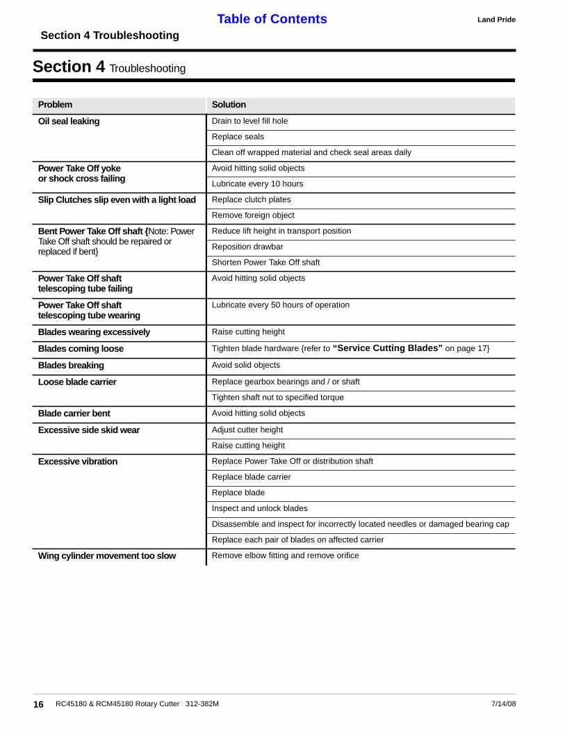
Section 4 Troubleshooting
16 RC45180 & RCM45180 Rotary Cutter 312-382M 7/14/08
Problem Solution
Oil seal leaking Drain to level fill hole
Replace seals
Clean off wrapped material and check seal areas daily
Power Take Off yokeor shock cross failing
Avoid hitting solid objects
Lubricate every 10 hours
Slip Clutches slip even with a light load Replace clutch plates
Remove foreign object
Bent Power Take Off shaft {Note: PowerTake Off shaft should be repaired orreplaced if bent}
Reduce lift height in transport position
Reposition drawbar
Shorten Power Take Off shaft
Power Take Off shafttelescoping tube failing
Avoid hitting solid objects
Power Take Off shafttelescoping tube wearing
Lubricate every 50 hours of operation
Blades wearing excessively Raise cutting height
Blades coming loose Tighten blade hardware {refer to “Service Cutting Blades” on page 17}
Blades breaking Avoid solid objects
Loose blade carrier Replace gearbox bearings and / or shaft
Tighten shaft nut to specified torque
Blade carrier bent Avoid hitting solid objects
Excessive side skid wear Adjust cutter height
Raise cutting height
Excessive vibration Replace Power Take Off or distribution shaft
Replace blade carrier
Replace blade
Inspect and unlock blades
Disassemble and inspect for incorrectly located needles or damaged bearing cap
Replace each pair of blades on affected carrier
Wing cylinder movement too slow Remove elbow fitting and remove orifice
Section 5 Maintenance and Lubrication
Land Pride Table of Contents
Section 5 Maintenance and Lubrication
MaintenanceProper servicing and adjustment is the key to the long lifeof any farm implement. With careful and systematic in-spection, you can avoid costly maintenance, time and re-pair.
For safety reasons, each maintenance operation must beperformed wiht tractor PTO disengaged, the cutter low-ered completely to the ground or on safely supportedblocking, tractor engine shut off and ignition key removed.
1. After using your cutter for several hours, check allbolts to be sure they are tight.
2. After transporting your cutter for several hours, checkall wheel lugs, bolts and nuts to be sure they are tight.Always maintain proper air pressure in the tires.
Service Cutting Blades1. Both blades on each dishpan should be sharpened at
the same angle as the original cutting edge and mustbe replaced or reground at the same time to maintainproper balance in the cutting unit.
IMPORTANT: Replace blades with genuine Land Prideblades only. If one blade is to be replaced, the matingblade {on the same carrier} must also be replaced.
2. Both blades on each dishpan should weigh the same af-ter sharpening.
3. When replacing or sharpening the cutter blades, exam-ine bolts and hardware for excessive wear and replace ifnecessary.a. Torque blade bolt lock nut to 450 ft. pounds. An ex-
tended cheater bar may be required to achieveproper torque.
b. Carefully check the cutting edges of the blades in re-lation to the blade carrier rotation diagram below toensure correct blade placement.
! CAUTION!Installation of the longer blades on the wing decks will cause animmediate operating hazard.
NOTE: Check tightness of bolts periodically, usingthe “Torque Values Chart” on 24 as a guide.
NOTE: Do not remove any more material than nec-essary when sharpening blades.
7/14/08
4. Blade Dishpan Replacement:Dishpan nut on gearbox output shafts should be torquedto 450 foot/pounds and cotter pin installed in nut with legssecurely bent around nut.
Skid Shoe Service & ReplacementThe center deck skid shoes should be checked periodical-ly for wear and replaced is necessary. Order center deckskid shoe Land Pride part #312-218H. No adjustment isrequired.
! CAUTION!Skid shoe replacement must be done with the deck raised to thetransport position and securely blocked. Engage parking brake,shut off tractor, remove key and disengage PTO before adjustingor replacing these parts.
! WARNING!Excessive wear on skids may cause inadequate operation of cut-ter and create a safety hazard!
The wing deck skid shoes should be checked periodicallyfor wear. Excessive leading edge wear can be repaired byinterchanging the LH wing skid with the RH wing skid. Ifboth leading edges have been worn down, order skid shoeLand Pride part # 312-446H.
Skid ShoesTo replace center deck skid shoes:
Refer to Figure 5-2:a. Attach skid shoe to cutter, using four 1/2" bolts
lock washers and hex nuts.b. Repeat for opposite skid shoe.
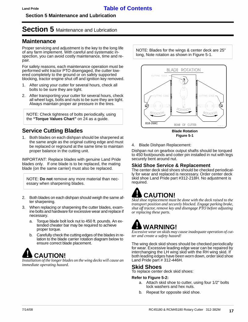
NOTE: Blades for the wings & center deck are 25"long, Note rotation as shown in Figure 5-1.
818-268C
Blade RotationFigure 5-1
17RC45180 & RCM45180 Rotary Cutter 312-382M
Section 5 Maintenance and Lubrication
Land PrideTable of Contents
To replace wing deck shoes:
Refer to Figure 5-3:a. Attach skid shoe to cutter, using three 1/2" car-
riage bolts flat washers, lock washers and hexnuts.
b. Repeat for opposite skid shoe.
Clutch Run-InRefer to Figure 5-4:
The clutch should slip during operation to protect the cut-ter from excessive loads.
Prior to initial operation and after long periods of inactivity,the Friction Clutch should be "run-in".
Clutch Run-InFigure 5-4
10103
18 RC45180 & RCM45180 Rotary Cutter 312-382M
1. Tighten all 4 nuts uniformly until the spring load is lowenough that the clutch slips freely with the PTO en-gaged.
2. Turn nuts fully back. Clutch is ready for use.
Storage1. At the end of the working season or when the cutter
will not be used for a long period, it is good practice toclean off any dirt or grease that may have accumulat-ed on the cutter and any of the moving parts. It may benecessary to scrape off compacted dirt from the bot-tom of the deck, then use a garden hose to thoroughlyclean the surface.
2. Check the blades for wear and replace if necessary.See "Maintenance & Lubrication".
3. Inspect the cutter for loose, damaged or worn partsand adjust or replace if needed.
4. Lubricate as noted in "Maintenance & Lubrication"beginning on page 19.
5. Repaint parts where paint is worn or scratched to pre-vent rust. Aerosol Buckskin touch-up paint is avail-able from your dealer. Order Land Pride part #821-011C.
6. Replace all damaged or missing decals.7. Store the cutter inside if possible. Inside storage will
reduce maintenance and make for a longer cutter life.
7/14/08
14178
Wing Deck Skid ShoeFigure 5-3
14177
Center Deck Skid ShoeFigure 5-2

Section 5 Maintenance and Lubrication
Land Pride Table of Contents
Lubrication
7/14/08
50Multipurposespray lube
Multipurposegrease lube
Multipurposeoil lube
Intervals at whichlubrication is required
LubricationLegend
13918
50
14099
14176
Axle Hub BearingRepack wheel bearings
Type of Lubrication: Wheel Bearing Grease
Quantity = Coat Generously
NOTE: The tailwheel hub is equipped with a relief hole locat-ed directly opposite the grease fitting. The relief hole releas-es pressure from inside the hub casting when it is greased.The hub should be greased until grease purges from the re-lief hole.
50
Wing Hinges (6)Type of Lubrication: Multi-Purpose
Quantity = As required
AsRequired
Ratchet Jack
Type of Lubrication: Multi-Purpose
Quantity = As required
19RC45180 & RCM45180 Rotary Cutter 312-382M
20
Section 5 Maintenance and Lubrication
RC45180 & RCM45180 Rotary Cutter 312-382M
Land PrideTable of Contents
14105
14052
50
14180
14051
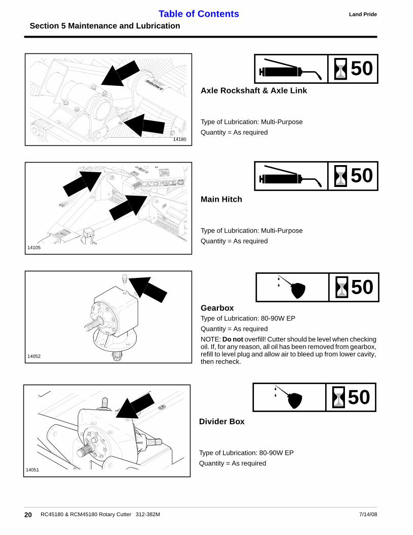
Axle Rockshaft & Axle Link
Type of Lubrication: Multi-Purpose
Quantity = As required
50
Main HitchType of Lubrication: Multi-Purpose
Quantity = As required
50
GearboxType of Lubrication: 80-90W EPQuantity = As required
NOTE: Do not overfill! Cutter should be level when checkingoil. If, for any reason, all oil has been removed from gearbox,refill to level plug and allow air to bleed up from lower cavity,then recheck.
50
Divider BoxType of Lubrication: 80-90W EP
Quantity = As required
7/14/08

Section 5 Maintenance and Lubrication
7/14/08
Land Pride Table of Contents
12726
12725
10
14191
Driveline Shaft
Type of Lubrication: Multi Purpose
Quantity = Coat Generously
25
Drive line ShaftsType of Lubrication: Multipurpose Grease
8
PTO Constant Velocity ShaftType of Lubrication: Multipurpose GreaseNOTE: To extend the life of the constant velocity joint,extensive lubrication must be performed every 8 hoursof operation!
a. The constant velocity joint should be greased ina straight position forcing grease through thepassages and into the cavity. After lubrication,grease should be visible around the ball joints.
b. The constant velocity driveline comes equippedwith a grease zerk in the outer telescopingmember and must be greased every 8 hours toprevent premature failure of the joint.
c. Grease fittings are located on the u-joints anddriveline shields and should be lubricated every8 hours of operation.
21RC45180 & RCM45180 Rotary Cutter 312-382M
Section 5 Maintenance and Lubrication
Land PrideTable of Contents
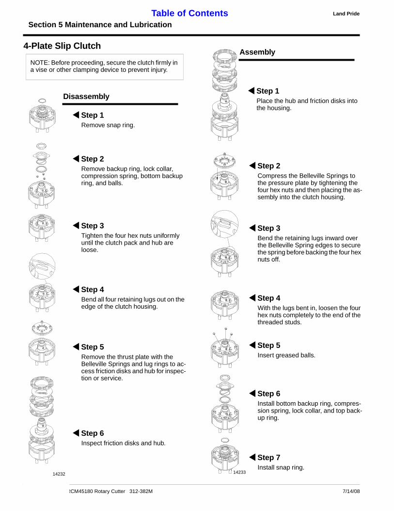
4-Plate Slip Clutch
NOTE: Before proceeding, secure the clutch firmly ina vise or other clamping device to prevent injury.
22 RC4518
14
Step 1Place the hub and friction disks intothe housing.
Disassembly
0 & RCM45180 Rotary Cutter 312-382M
1
Step 1Remove snap ring.
Step 2Remove backup ring, lock collar,compression spring, bottom backupring, and balls.
Step 3Tighten the four hex nuts uniformlyuntil the clutch pack and hub areloose.
Step 4Bend all four retaining lugs out on theedge of the clutch housing.
Step 5Remove the thrust plate with theBelleville Springs and lug rings to ac-cess friction disks and hub for inspec-tion or service.
Step 6Inspect friction disks and hub.
232
Assembly
7/14/08
4233
Step 2Compress the Belleville Springs tothe pressure plate by tightening thefour hex nuts and then placing the as-sembly into the clutch housing.
Step 3Bend the retaining lugs inward overthe Belleville Spring edges to securethe spring before backing the four hexnuts off.
Step 4With the lugs bent in, loosen the fourhex nuts completely to the end of thethreaded studs.
Step 5Insert greased balls.
Step 6Install bottom backup ring, compres-sion spring, lock collar, and top back-up ring.
Step 7Install snap ring.

Section 6 Specifications and Capacities
Land Pride Table of Contents
Section 6 Specifications and Capacities
237/14/08 RC45180 & RCM45180 Rotary Cutter 312-382M
RC45180 & RCM45180 Rotary Cutter
Cutting WidthOverall Width
Minimum Transport Width
180”190”96”
Cutting Height 2” - 14”
Overall Length 204”
Deck Material Thickness 10 gauge
Deck Height 10”
Hitch Type Pull Self - Leveling
Blades - 6 (2 per Carrier) 1/2” x 4” Heat Alloy StealFree SwingingHigh LiftLow Friction
Blade Tip Speed 540 RPM PTO: FPM RPMCenter Blade 14,853 788Wing Blade 14,112 907
1000 RPM PTO:Center Blade 15,569 826Wing Blade 14,486 930
Blade Holders Center: 3/16” x 27” Oval PanWing: 3/16” x 15” Round Pan
PTO Drive Shafts 540 PTO: ASAE Category 5 {Input Shafts}ASAE Category 4 {Output Shafts}1,000 PTO: ASAE Category 4 {Input / Output}
Driveline Slippage Protection Dual plate Bellevile type slip clutches on each blade gearbox
Power Divider 540 RPM: PTO Driven 1:1.15 Speed-UpTapered Roller Bearings, Beveled GearsCast Iron Housing, 125 Horse Power
1000 RPM: PTO Driven 1.3:1 ReductionTapered Roller Bearings, Beveled GearsCast Iron Housing, 180 Horse Power
Gear Boxes 540 RPM: PTO Driven 1:1.46 Speed-UpTapered Roller Bearings, Beveled GearsCast Iron Housing, 75 Horse Power
1000 RPM: {wings} PTO Driven 1:1.21 Speed-Up;{center} 1.21:1 ReductionTapered Roller Bearings, Beveled GearsCast Iron Housing, 75 Horse Power
Tailwheel - Pull Type 6.00 x 9 x 21 Laminated or5 x 15 Rim only or 21” Solid Core or25.5 x 8.0-14 18 Ply-tube-type
Shock Load Suspension Four Compression type springs on center wheelsFour Rubber Bumper cushions on wing wheels
Machine Weight (With front / rear chain guards) 4,400 lbs.
Tongue Weight 1,600 lbs.
Recommended PTO Horse Power 50 - 150

Section 7 Appendix
Land PrideTable of Contents
Section 7 Appendix
Torque Values Chart for Common Bolt Sizes
in-tpi1 N · m2 ft-lb3 N · m ft-lb N · m ft-lb mm x pitch4 N · m ft-lb N · m ft-lb N · m ft-lb
1/4" - 20 7.4 5.6 11 8 16 12 M 5 X 0.8 4 3 6 5 9 7
1/4" - 28 8.5 6 13 10 18 14 M 6 X 1 7 5 11 8 15 11
5/16 - 18 15 11 24 17 33 25 M 8 X 1.25 17 12 26 19 36 27
5/16" - 24 17 13 26 19 37 27 M 8 X 1 18 13 28 21 39 29
3/8" - 16 27 20 42 31 59 44 M10 X 1.5 33 24 52 39 72 53
3/8" - 24 31 22 47 35 67 49 M10 X 0.75 39 29 61 45 85 62
7/16" - 14 43 32 67 49 95 70 M12 X 1.75 58 42 91 67 125 93
7/16" - 20 49 36 75 55 105 78 M12 X 1.5 60 44 95 70 130 97
1/2" - 13 66 49 105 76 145 105 M12 X 1 90 66 105 77 145 105
1/2" - 20 75 55 115 85 165 120 M14 X 2 92 68 145 105 200 150
9/16" - 12 95 70 150 110 210 155 M14 X 1.5 99 73 155 115 215 160
9/16" - 18 105 79 165 120 235 170 M16 X 2 145 105 225 165 315 230
5/8" - 11 130 97 205 150 285 210 M16 X 1.5 155 115 240 180 335 245
5/8" - 18 150 110 230 170 325 240 M18 X 2.5 195 145 310 230 405 300
3/4" - 10 235 170 360 265 510 375 M18 X 1.5 220 165 350 260 485 355
3/4" - 16 260 190 405 295 570 420 M20 X 2.5 280 205 440 325 610 450
7/8" - 9 225 165 585 430 820 605 M20 X 1.5 310 230 650 480 900 665
7/8" - 14 250 185 640 475 905 670 M24 X 3 480 355 760 560 1050 780
1" - 8 340 250 875 645 1230 910 M24 X 2 525 390 830 610 1150 845
1" - 12 370 275 955 705 1350 995 M30 X 3.5 960 705 1510 1120 2100 1550
1-1/8" - 7 480 355 1080 795 1750 1290 M30 X 2 1060 785 1680 1240 2320 1710
1 1/8" - 12 540 395 1210 890 1960 1440 M36 X 3.5 1730 1270 2650 1950 3660 2700
1 1/4" - 7 680 500 1520 1120 2460 1820 M36 X 2 1880 1380 2960 2190 4100 3220
1 1/4" - 12 750 555 1680 1240 2730 2010
1 3/8" - 6 890 655 1990 1470 3230 2380 1 in-tpi = nominal thread dia .in inches-threads per inch
1 3/8" - 12 1010 745 2270 1670 3680 2710 2 N· m = newton-meters
1 1/2" - 6 1180 870 2640 1950 4290 3160 3 ft-lb= foot pounds
1 1/2" - 12 1330 980 2970 2190 4820 3560 4 mm x pitch = nominal thread dia. in millimeters x thread pitch
5.8 8.8 10.9
Class 5.8 Class 8.8 Class 10.9
Bolt Head Identification
Bolt Size(Metric)Grade 2 Grade 5 Grade 8
Bolt Head Identification
Bolt Size(Inches)
Tire Inflation ChartTire Size Inflation PSI
25.5 x 8.0” - 14 35
24 RC45180 & RCM45180 Rotary Cutter 312-382M 7/14/08

WarrantyLand Pride warrants to the original purchaser that this Land Pride product will
be free from defects in material and workmanship for a period of one year, fromthe date of delivery to the end user, when used as intended and under normal ser-vice and conditions for personal use; and 6 months for municipalities, golf cours-es, sod farms and rental purposes. This Warranty is limited to the replacement ofany defective part by Land Pride and the installation by the dealer of any such re-placement part, and does not cover common wear items such as blades, belts,tines, etc. Land Pride reserves the right to inspect any equipment or parts whichare claimed to have been defective in material or workmanship.
This Warranty does not apply to any part or product which in Land Pride’s judg-ment shall have been misused or damaged by accident or lack of normal mainte-nance or care, or which has been repaired or altered in a way which adverselyaffects its performance or reliability, or which has been used for a purpose forwhich the product is not designed. Misuse also specifically includes failure toproperly maintain oil levels, grease points, and driveline shafts.
Claims under this Warranty must be made to the dealer which originally soldthe product and all warranty adjustments must be made through such dealer.Land Pride reserves the right to make changes in materials or design of the prod-uct at any time without notice.
This Warranty shall not be interpreted to render Land Pride liable for damagesof any kind, direct, consequential, or contingent to property. Furthermore, LandPride shall not be liable for damages resulting from any cause beyond its reason-able control. This Warranty does not extend to loss of crops, any expense or lossfor labor, supplies, rental machinery or for any other reason.
No other warranty of any kind whatsoever, express or implied, is madewith respect to this sale; and all implied warranties of merchantability andfitness for a particular purpose which exceed the obligations set forth in thiswritten warranty are hereby disclaimed and excluded from this sale.
This Warranty is not valid unless registered with Land Pride within 30 days fromthe date of delivery to the end user.

Corporate Office: PO. Box 5060Salina, Kansas 67402-5060 USA
www.landpride.com