operator's manual lathe, brake drum, … 9-4910-446-10 department of t he army technical manual...
TRANSCRIPT

TM 9-4910-446-10
DEPARTMENT OF T HE ARMY TECHNICAL MANUAL
OPERATOR'S MANUAL
LATHE, BRAKE DRUM, FLOORMOUNTED, 60 INCH RATED SWING,
25 INCH MAXIMUM DRUM DIAME-TER, W/GRINDING PROVISIONS,1 HORSEPOWER DRIVE MOTOR,
1/2 HORSEPOWER GRINDING MOTOR,115-VOLT, 60-CYCLE, SINGLE-PHASE
(STAR MACHINE AND TOOL COM-PANY MODEL 1960) (4910-516-6192)
This reprint includes all changes in effect at the time ofpublication -Change 1.
HEADQUARTERS, DEPARTMENT OF THE ARMY
MAY 1965

HEADQUARTERSDEPARTMENT OF THE ARMY
WASHINGTON, D. C., 19 May 1965
TM 9-4910-446-10 is published for the information and use of all concerned.
By Order of the Secretary of the Army:HAROLD K. JOHNSON,General, United States Army,
Official: Chief of Staff.J. C. LAMBERT,Major General, United State Army,
The Adjutant General
Distribution:Active Army:
USASA (1) Ord Test Activity Yuma (1)DCSLOG (1) OART (1)CNGB (1) ARMISH (1)TSG (1) USAAVCOM (2)CofEngrs (2) APG (2)CofSptS (2) 4th USASA Fld Sta (1)Dir of Trans (1) USACOMZEUR (2)CC-E (1) DPG (1)USAOCDA (1) USAPRDC (1)USCONARC (3) QM Fld Maint Shops (2)USAMC (2) Engr Fld Maint Shops (2)USACDC (1) MAAG Iran, Vietnam (1)ARADCOM (2) Units org under fol TOE:ARADCOM Rgn (2) (2 copies each)LOGCOMD (3) 6-635OS Maj Comd (2) except 7
USASETAF (1) 9-7USAMUCOM (3) 9-25USAWECOM (74) 9-26USASMC (2) 9-65Armies (3) except 9-66
Seventh USA (5) 9-127EUSA (5) 9-197
Corps (2) 9-217USAC (2) 9-357Ft Belvoir (1) 9-500 (CA, CC, DA)Ft Eustis (1) 10-445USA Ord Seh (2) 10-443GENDEP (2) 17Army Dep (3) 29-51Arsenals (2) 29-55USDB (Ft Leavenworth) (1) 29-56USA Cold Rgn Rsch Engr Lab (1) 29-57
NG: State AG (2); United-Same as Active Army except allowance in one copy to each unit.USAR: None.For explanation of abbreviations used, see AR 32-50.

TM 9-4910-446-10C 1
CHANGE HEADQUARTERSDEPARTMENT OF THE ARMY
No. 1 WASHINGTON, D.C., 16 January 1973
Operator's Manual
LATHE, BRAKE DRUM, FLOOR MOUNTED,
60 INCH RATED SWING, 25 INCH
MAXIMUM DRUM DIAMETER, W/GRINDING
PROVISIONS, 1 HORSEPOWER DRIVE MOTOR,
1/2 HORSEPOWER GRINDING MOTOR,
115-VOLT, 60-CYCLE, SINGLE-PHASE
(STAR MACHINE AND TOOL COMPANY
MODEL 1960) (4910-516-6192)
This change is current as of 6 December 1972
TM 9-4910-446-10, 19 May 1965, is changed as follows:
1. This change identifies the type of catalog maintenance action taken in connection with the updating of previouslypublished data.
2. This change is separated by additions, deletions, and changes and is a list of items added, deleted, and/or changedsince the last previously published data.
3. All Federal stock numbers and reference numbers, additions, deletions, and changes should be made to the indexes.
4. Parts included with end items and considered a component or part of the item configuration, are listed on the followingtables. The part numbers listed are for Star Machine and Tool CompanyModel 1960.
5. The reporting of errors, omissions, and recommendations for improving this publication by the individual user isencouraged. Reports should be submitted on DA Form 2028 (Recommended Changes to Publications) and forwardeddirect to Commander, US Army Weapons Command, ATTN: AMSWE-MAS, Rock Island, IL 61201.
}
1
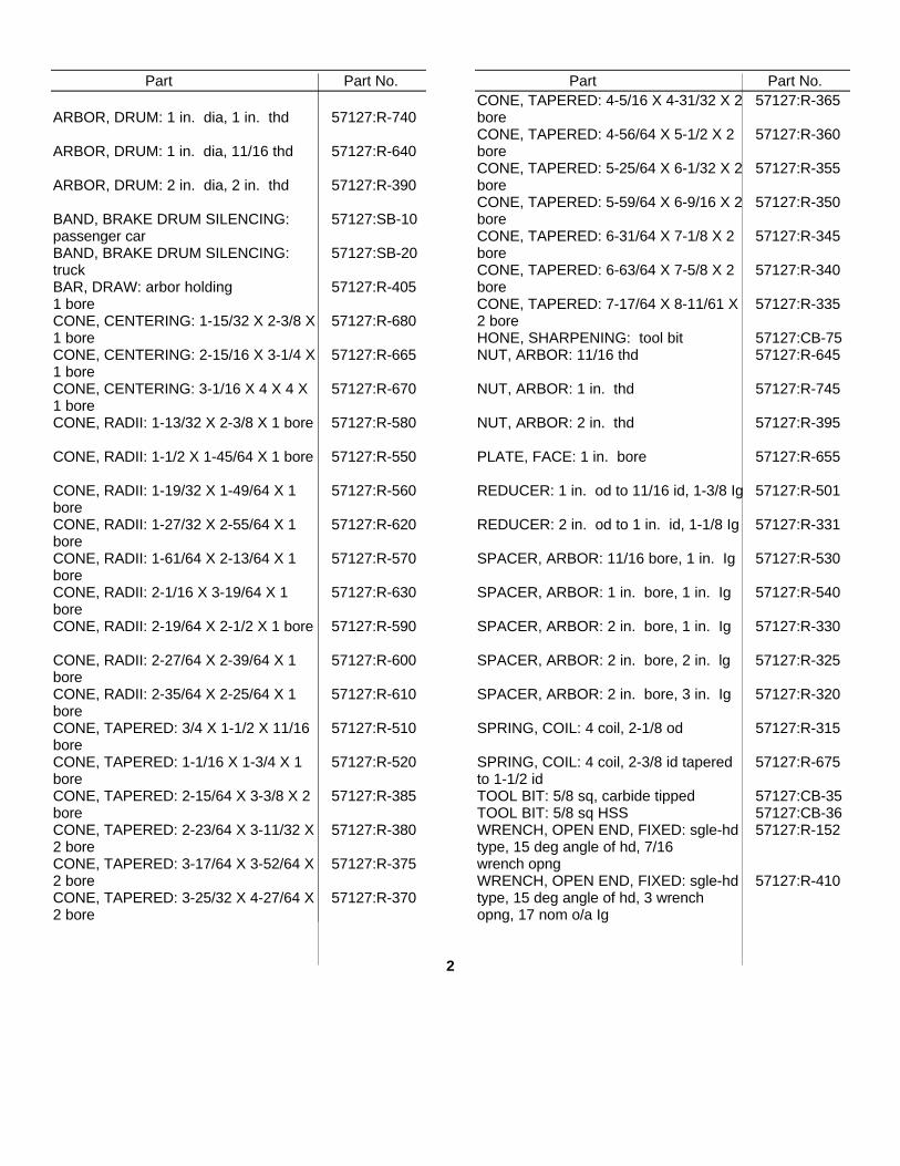
Part Part No.
ARBOR, DRUM: 1 in. dia, 1 in. thd 57127:R-740
ARBOR, DRUM: 1 in. dia, 11/16 thd 57127:R-640
ARBOR, DRUM: 2 in. dia, 2 in. thd 57127:R-390
BAND, BRAKE DRUM SILENCING: 57127:SB-10passenger carBAND, BRAKE DRUM SILENCING: 57127:SB-20truckBAR, DRAW: arbor holding 57127:R-4051 boreCONE, CENTERING: 1-15/32 X 2-3/8 X 57127:R-6801 boreCONE, CENTERING: 2-15/16 X 3-1/4 X 57127:R-6651 boreCONE, CENTERING: 3-1/16 X 4 X 4 X 57127:R-6701 boreCONE, RADII: 1-13/32 X 2-3/8 X 1 bore 57127:R-580
CONE, RADII: 1-1/2 X 1-45/64 X 1 bore 57127:R-550
CONE, RADII: 1-19/32 X 1-49/64 X 1 57127:R-560boreCONE, RADII: 1-27/32 X 2-55/64 X 1 57127:R-620boreCONE, RADII: 1-61/64 X 2-13/64 X 1 57127:R-570boreCONE, RADII: 2-1/16 X 3-19/64 X 1 57127:R-630boreCONE, RADII: 2-19/64 X 2-1/2 X 1 bore 57127:R-590
CONE, RADII: 2-27/64 X 2-39/64 X 1 57127:R-600boreCONE, RADII: 2-35/64 X 2-25/64 X 1 57127:R-610boreCONE, TAPERED: 3/4 X 1-1/2 X 11/16 57127:R-510boreCONE, TAPERED: 1-1/16 X 1-3/4 X 1 57127:R-520boreCONE, TAPERED: 2-15/64 X 3-3/8 X 2 57127:R-385boreCONE, TAPERED: 2-23/64 X 3-11/32 X 57127:R-3802 boreCONE, TAPERED: 3-17/64 X 3-52/64 X 57127:R-3752 boreCONE, TAPERED: 3-25/32 X 4-27/64 X 57127:R-3702 bore
Part Part No.CONE, TAPERED: 4-5/16 X 4-31/32 X 2 57127:R-365boreCONE, TAPERED: 4-56/64 X 5-1/2 X 2 57127:R-360boreCONE, TAPERED: 5-25/64 X 6-1/32 X 2 57127:R-355boreCONE, TAPERED: 5-59/64 X 6-9/16 X 2 57127:R-350boreCONE, TAPERED: 6-31/64 X 7-1/8 X 2 57127:R-345boreCONE, TAPERED: 6-63/64 X 7-5/8 X 2 57127:R-340boreCONE, TAPERED: 7-17/64 X 8-11/61 X 57127:R-3352 boreHONE, SHARPENING: tool bit 57127:CB-75NUT, ARBOR: 11/16 thd 57127:R-645
NUT, ARBOR: 1 in. thd 57127:R-745
NUT, ARBOR: 2 in. thd 57127:R-395
PLATE, FACE: 1 in. bore 57127:R-655
REDUCER: 1 in. od to 11/16 id, 1-3/8 Ig 57127:R-501
REDUCER: 2 in. od to 1 in. id, 1-1/8 Ig 57127:R-331
SPACER, ARBOR: 11/16 bore, 1 in. Ig 57127:R-530
SPACER, ARBOR: 1 in. bore, 1 in. Ig 57127:R-540
SPACER, ARBOR: 2 in. bore, 1 in. Ig 57127:R-330
SPACER, ARBOR: 2 in. bore, 2 in. lg 57127:R-325
SPACER, ARBOR: 2 in. bore, 3 in. Ig 57127:R-320
SPRING, COIL: 4 coil, 2-1/8 od 57127:R-315
SPRING, COIL: 4 coil, 2-3/8 id tapered 57127:R-675to 1-1/2 idTOOL BIT: 5/8 sq, carbide tipped 57127:CB-35TOOL BIT: 5/8 sq HSS 57127:CB-36WRENCH, OPEN END, FIXED: sgle-hd 57127:R-152type, 15 deg angle of hd, 7/16wrench opngWRENCH, OPEN END, FIXED: sgle-hd 57127:R-410type, 15 deg angle of hd, 3 wrenchopng, 17 nom o/a Ig
2
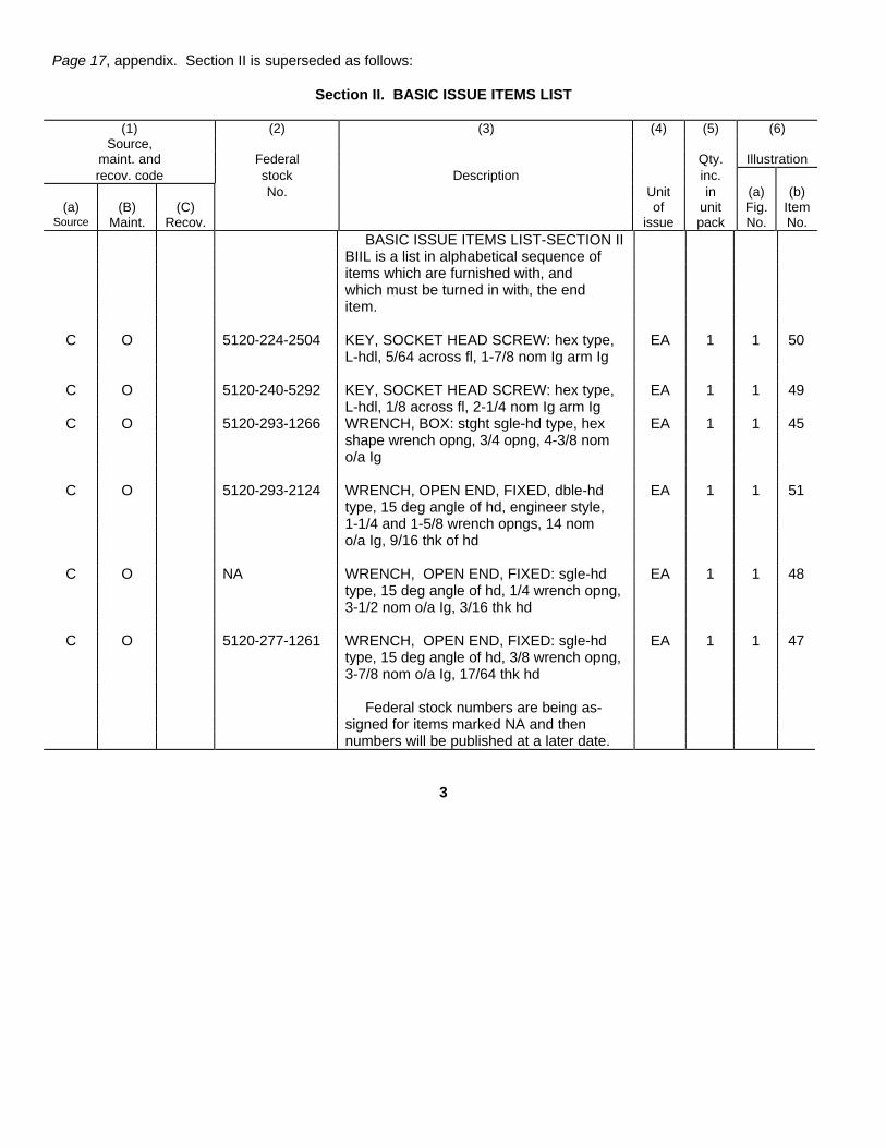
Page 17, appendix. Section II is superseded as follows:
Section II. BASIC ISSUE ITEMS LIST
(1) (2) (3) (4) (5) (6)Source,
maint. and Federal Qty. Illustrationrecov. code stock Description inc.
No. Unit in (a) (b)(a) (B) (C) of unit Fig. Item
Source Maint. Recov. issue pack No. No.BASIC ISSUE ITEMS LIST-SECTION II
BIIL is a list in alphabetical sequence ofitems which are furnished with, andwhich must be turned in with, the enditem.
C O 5120-224-2504 KEY, SOCKET HEAD SCREW: hex type, EA 1 1 50L-hdl, 5/64 across fl, 1-7/8 nom Ig arm Ig
C O 5120-240-5292 KEY, SOCKET HEAD SCREW: hex type, EA 1 1 49L-hdl, 1/8 across fl, 2-1/4 nom Ig arm Ig
C O 5120-293-1266 WRENCH, BOX: stght sgle-hd type, hex EA 1 1 45shape wrench opng, 3/4 opng, 4-3/8 nomo/a Ig
C O 5120-293-2124 WRENCH, OPEN END, FIXED, dble-hd EA 1 1 51type, 15 deg angle of hd, engineer style,1-1/4 and 1-5/8 wrench opngs, 14 nomo/a Ig, 9/16 thk of hd
C O NA WRENCH, OPEN END, FIXED: sgle-hd EA 1 1 48type, 15 deg angle of hd, 1/4 wrench opng,3-1/2 nom o/a Ig, 3/16 thk hd
C O 5120-277-1261 WRENCH, OPEN END, FIXED: sgle-hd EA 1 1 47type, 15 deg angle of hd, 3/8 wrench opng,3-7/8 nom o/a Ig, 17/64 thk hd
Federal stock numbers are being as-signed for items marked NA and thennumbers will be published at a later date.
3
By Order of the Secretary of the Army:
CREIGHTON W. ABRAMSGeneral, United States Army
Official: Chief of StaffVERNE L. BOWERSMajor General, United States ArmyThe Adjutant General
Distribution:Active Army
DCSLOG (1) WECOM (10)TSG (1) OS Maj Comd (5)COE (6) LOGCOMD (3)Dir of Trans (1) Armies (3) exceptCONARC (3) 7th USA (5)AMC (10) 8th USA (5)MUCOM (2) Corps (2)ARADCOM (2) USACOMZEUR (2)ARADCOM Rgn (2) USARYIS (1)TACOM (5) ANAD (2)AVSCOM (10) TOE 55-465 (2)
NG: None.
USAR. None
For explanation of abbreviations used, see AR 310-50.

Section IParagraphs 1-1 to 1-22
SECTION IUSE AND MAINTENANCE
Fig. 1-1. Brake Drum Lathe
1-1. INTRODUCTION1-2. The Star Brake Drum Lathe, Model 1960 is designedto put a smooth, accurate finish on used or unfinishedbrake drums (see figure 1-1).1-3. The Model 1960 wilt handle passenger car drums aswell as being capable of turning the largest and heaviesttruck drums.1-4. The Model 1960 is designed to keep maintenanceexpenses at a minimum and operating efficiency at amaximum.1-5. The following instructions and parts breakdown willhelp ensure many years of high quality, troublefree drumturning. Numbers in parentheses refer to item numbers(see figure 2-1).1-6. TABLE OF SPECIFICATIONS
Drum Capacity Range (dia.) ....................... 6" to 42"Drum Cutting Depth (face).................................. 10"Speeds, Number of Changes.........................InfiniteSpeeds, Cutting Range................... 30 to 150 r.p.m.Swing ................................................................ 60"Motor ..................................1 h.p., 115-230v., 60C.,
Single Phase 1725 r.p.m.Feed, Range.............................O to Rapid TraverseNumber of Feeds...........................................InfiniteWeight ........................................................590 lbs.
1-7. INSTALLATION1-8. Remove machine and all accessories from shippingcontainer.1-9. Check all parts with packing slip to insure all itemsare included.1-10. Clean the entire machine, adapters, andaccessories with a good grease solvent to remove theprotective coating on the machined surfaces,.1-11. Place machine in desired position and securely boltit to the floor. Make sure machine is level by using alevel on the top plate of the cabinet.1-12, Install the 2" Arbor, R-390, into the Spindle (28) andtighten until Arbor is drawn up tightly in Spindle (28).1-14. Place the Vertical Tube (184) over the HorizontalTube (197) and position the Horizontal Tube (197) overthe plug which is welded to the base.
1-15. Fasten the Bottom Mounting Plate (198) to thebase of the Horizontal Tube, (197).1-16. By use of a plumb bob, level, and shims,permanently position the Bottom Mounting Plate (198) sothat the Horizontal Tube (197) is directly beneath theArbor and level to the floor. Tighten Cap Screw (200) atrear of Horizontal Tube (197).1-17. Swing the Vertical Tube (184) into the uprightposition and slide it toward the Arbor. Raise the AdjustingBushing (187) by hand until the Rod End Bearing (188)will slide over the end of Arbor and the Vertical Tube(184) is directly below Arbor. Fasten the Vertical Tube(184) to the Horizontal Tube (197) by tightening theLocking Screw Shaft (195). Place Cam Shaft (190) in theup position until Pin (194) hits Stop Pin (193). Rotate theAdjusting Bushing (187) until you feel it touch the Cam(191). This is done by slowly moving the Cam Shaft (190)while you are rotating the Adjusting Bushing (187) untilyou feel a slight drag on the Cam (1917). Tighten theJam Nut (189). The outboard support is now permanentlyadjusted.1-18. Place Tool Bit, CB-35, into Boring Bar (77) andfasten securely with the two Square Head Set Screws(78). The tool bit slot in the end of the Boring Bar (77) isdeep enough to enable several degrees of adjustment ofthe tool bit angle. The groove running along the BoringBar (77) should be lined up with the slit in the CompoundRest (73).1-19. Position Lamp (121) over Lamp Bracket (122) andplug into Receptacle (85). Use standard bulb, 75 watts orless, moistening bulb neck before slipping it throughsilicone grommet at the base of reflector.After screwing bulb into socket, make sure air spacebetween shade and reflector is equal on all sides.1-20. Plug machine into 115 volt outlet and the machineis now properly installed.1-21. OPERATIONAL PROCEDURES1-22. Mount drum on arbor using one of the followingmethods which apply. Be sure that the Arbor is mountedin Spindle (28) before mounting hub and drum assembly.a.-Loose Drum Set-up. Select proper Tapered Cone to fit
in center of drum. Place one Face Plate on Arborfollowed by the Spring and Tapered Cone. Placedrum on Arbor over Tapered Cone and push drum upto pads of Face Plate. Place other Face Plate onArbor and push up to drum. Place additional Spacerson Arbor so that the two Face Plates can be tightenedtogether when the Arbor Nut is put on the end ofArbor and tightened. Make sure that the face platepads are riding on a smooth dean surface of the drum(see figure 1-2).
b.-Tapered Hub. Select the proper Tapered Cones to fitin drum hub. On some drums the Tapered Cones goin about 1/4 of an inch. Place Tapered Cone forinside
1

Section IParagraphs 1-23 to 1-44
of tapered hub onto Arbor followed by the drum andoutside Tapered Cone. Place additional Spacers ontoArbor so that when the Arbor Nut is tightened at theend of the Arbor, the two Tapered Cones are drawnup tightly against the tapered hub (see figure 1-3).
c.-Ball Bearing Equipped Hub. Select the proper RadiiCone to fit into the inner and outer bearing cups.Radius of Radii Cone selected should seat in Centerof bearing cup radius. Place Radii Cone for innerbearing cup onto Arbor followed by drum and RadiiCone for outer bearing cup. Place additional Spacerson Arbor so that when the Arbor Nut on the end ofArbor is tightened, the two Radii Cones are drown upsecurely to the bearing cups. Make sure bearing cupsand Radii Cones are clean before mounting (seefigure 1-4).
d.-Tapered Bearing Equipped Hub. Select the properRadii Cone to fit into the inner and outer bearingcups. Radius of Radii Cone selected should seatsomewhere on cup bearing surface. In most cases,this will be approximately in the center of bearing cup.Place Radii Cone for inner bearing cup on Arbor,followed by hub and Radii Cone for outer bearing cup.Place additional Spacers on Arbor so that when theArbor Nut is tightened on the end of the Arbor, the twoRadii Cones will draw up securely to the bearing cupsand Radii Cones are clean before mounting (seefigure 1-5).
e.-Tapered Bearing Hub. (Truck). Select the properTapered Cones to fit into the inner and outer bearingcups. The Tapered Cone should fit so that it is almostcompletely inside the bearing cup. There areconditions when the Tapered Cone will barely enterthe cup or just about go through the cup. Place theTapered Cone for the inner bearing cup on the Arbor,followed by the drum and Tapered Cone for outerbearing cup. Place additional Spacers on the Arborso that when the Arbor Nut on the end of the Arbor istightened, the two Tapered Cones are drawn securelyagainst the bearing cups. Make sure that the TaperedCones and bearing cups are clean (see figure 1-6).
1-23. Place Brake Drum Silencing Band, SB-10 or SB-20, around drum and apply enough tension so that thedrum is snugly wrapped. On passenger drums, the BrakeDrum Silencing Band, SB-10, should be positioned evenwith the edge of open side of drum. The Brake DrumSilencing Band should not be too tight or too loose ondrum.1-24. If drum is to be turned with wheels mounted, thenthe outboard support should always be used.1-25. Before drum and wheel assembly is resting with fullweight on the Arbor, make sure that the Vertical Tube(184) of the outboard support is in place and the CamShaft (190) is In the up position.1-26. For best results, the outboard support should beused on all drum and wheel assemblies.1-27. The Boring Bar (77), Compound Rest (73), CrossSlide (59) and Apron (45) should be adjusted so that the
Tool Bit can be placed in the rear of the drum withoutinterference. This adjustment depends on the diameterand depth of the drum. The Boring Bar (77) can be slid inand out of the Compound Rest (73) by loosening the CapScrew (76). The Compound Rest (73) can be rotated byloosening Cap Screw (74) and Cap Screw (76) the CrossSlide (59) can be moved in or out by rotating Handle (71).1-28. Turn machine on at Switch (112). Make sure CutOff Switch (117) is also on.1-29. If drum has a prominent ridge on outer or inneredge of braking surface, remove with rough cut beforeobserving the following procedures.1-30. Bring Tool Bit into rear of drum by moving DirectionLever (208) down and moving Speed Lever (207) downinto the rapid traverse range.1-31. As Tool Bit approaches rear of drum, raise up onSpeed Lever (207) and move Direction Lever up toneutral position.1-32. Bring Tool Bit to maximum depth of drum byrotating Large Handwheel (182).1-33. Adjust Cut Off Rod (53) so that machine will shutoff after Tool Bit has cleared drum. The Cut Off Rod (53)con be adjusted by merely pushing it. The drag on theCut Off Rod (53) is set at the factory and should be suchthat the Cut Off Rod (53) will trip the Cut Off Switch (117)but not accidentally break it if the Apron (45) is handcranked.1-34. Advance Handle (71) until Tool Bit touches insidesurface of drum. Each graduation on the GraduatedCollar (68) represents .001" of travel of the Tool Bit.Advance Handle (71) an additional .10" into the drum.Lock Cross Slide (59) by tightening Thumb Screw (57).1-35. Rotate Handwheel (99) counter clockwise in orderthat the drum will rotate in the lower r.p.m.range.1-36. Move Direction Lever (208) up to move Tool Bit tothe right.1-37. Move Speed Lever (207) down into the rough cutrange and lock into position by rotating Speed Lever (207)clockwise. If drum does not clean up, repeat aboveprocedures.1-38. When Tool Bit leaves drum, move Direction Lever(208) down to neutral position.1-39. Remember Graduated Collar (68) reading, loosenThumb Screw (57) and rotate Handle (71) back .015".1-40. Move Direction Lever (208) down and unlockSpeed Lever (207) and move it down to the rapid traverserange.1-41. As Tool Bit approaches rear of drum, -raise SpeedLever (207) until Tool Bit stops moving.1-42. Move Direction Lever (208) up to neutral position.1-43. Bring Tool Bit to maximum depth of drum byrotating Large Handwheel (182).1-44. Turn Handle (71) to rough cut reading plus anadditional .002" and lock Cross Slide (59) by tighteningThumb Screw (57).
2
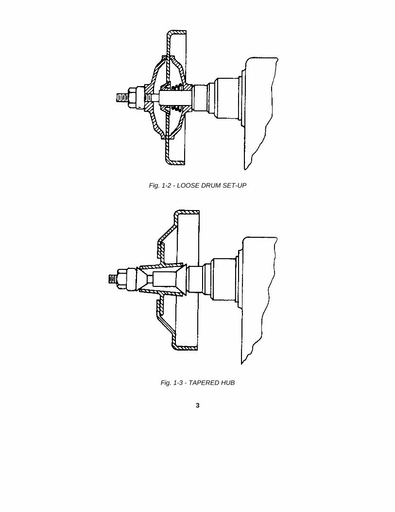
Fig. 1-2 - LOOSE DRUM SET-UP
Fig. 1-3 - TAPERED HUB
3

Fig. 1-4 - BALL BEARING EQUIPPED HUB
Fig. 1-5 - TAPERED BEARING EQUIPPED HUB
4

Fig. 1-6 - TAPERED BEARING HUB (TRUCK)
5

Section IParagraphs 1-45 to 1-57
1-45. Rotate Handwheel (99) clockwise until drum isrotating in the high r.p.m. range.1-46. Move Direction Lever (208) up and move SpeedLever (207) down into finish cut range and lock by rotatingSpeed Lever (207) clockwise.1-47. When Tool Bit leaves the drum, the drum shouldhave an accurate and smooth finish.1-48. Move Direction Lever (208) down to the neutralposition and raise Speed Lever (207) up to the upposition.1-49. Turn machine off at Switch (112) and remove drumfrom machine.1-50. The above procedures are for instruction purposesand are not necessarily correct for all cases.Drum condition determines the proper depth of cuts,carriage feed, and spindle r.p.m. As the operator gainsexperience with this machine, he will be able to make theproper settings for maximum performance, efficiency andaccuracy.1-51. MAINTENANCE PROCEDURES1-52. Lubricationa.-Main Bearings (3 & 4). Apply a few drops of light machine oil
(SAE #10) in both Head Oilers (5).b.-Lead Screw (42) and Lead Screw Nut (43). Apply a few
drops of light machine oil (SAE #10) along length of LeadScrew (42) once a week.
c.-Cross Slide (59). Apply a few drops of light machine oil (SAE#10) at Oiler (60) and between Graduated Collar (68) andEnd Plate (66).
d.-Bearing (161) and Pillow Block Bearing (166). Apply a fewdrops of light machine oil (SAE #10) at both oil cups insideGuard (173) every 90 days.
e.-Gear box. Maintain the oil level in the center of Oil Window(8) with gear oil (SAE #90 or MIL L 15019C, Grade 6135).Add oil by removing Vented Plug (6). Caution: Do not fillhigher than the top of Oil Window (8).
f.-Control Box (143). This box should be drained once eachyear or each 1500 hours of operation by removing DrainPlug (210). Twelve ounces of new oil (all purpose #80) orMIL L-2105) should be added at Vent Plug (209).
g.-Variable Speed Pulley (201). Lubricate grease fitting in rearof machine with one shot of light needle bearing greaseevery 90 days.
h.-Apron ways. Move Apron (45) to extreme front position, wipeaway all dirt or cutting particles and apply several drops oflight oil (SAE #10) to all exposed surfaces of the dovetailways. Move Apron (45) in the, opposite direction andrepeat above procedures. Perform weekly.
i.-Cross slide ways. Back out Cross Slide (59) to extreme outposition, wipe the dovetail surfaces clean and apply light oil(SAE #10) weekly.
j.-Wipe machine free of dust and cutting particles with oil ragdoily.
1-53. Trouble Shooting.a.-Problem: Chatter.
Reason:Wrong Cones and Adapters.Face Plate, R-655, making poor contact due to excessive
dirt between face plate pads and drum.
Dull Tool Bit.Misaligned Boring Bar (77).Failure to use Brake Drum Silencing Band, SB-10 or SB-20.Improper mounting of Brake Drum Silencing Band, SB-10 or SB-20.Spindle r.p.m. too slow or too fast for depth of cut.Outboard support not bolted to floor.The following areas should be checked for tightness:(1) Tool bit, CB-35 or CB-36.(2) Boring Bar (77).(3) Gib (61).(4) Gib (49).(5) Draw bar, R-405.(6) Arbor Nut, R-645, R-745 or R-395.(7) Drum on hub.(8) Bearing cup in hub.Failure to tighten Cross Slide (59), Thumb Screw (57).
b.-Problem: Loss of power.Reason.Low voltage to motor.Worn or loose drive belts.Dull tool bit.Failure to follow lubrication Instructions.
c.-Problem: Machine shuts off during operation.Reason: Cut Off Rod (53) not adjusted properly.Thermal overload switch (112) cuts off because machine is
overworked.d.-Problem: Machine will not start.
Reason: Cut Off Switch (117) Is in off position.Thermal overload Switch (112) has not had time to cool.
1-54. Calibration.a.-Gib (49) adjustment. Loosen Jam Nuts (51). Tighten Set
Screws (50) until Apron (45) looseness is taken up.Tighten Jam Nuts (51).
b.-Cross slide Gib (51) adjustment, Loosen Jam Nuts (63).Tighten Gib Screws (62) until Cross Slide (59) looseness istaken up. Tighten Jam Nuts (63).
c.-Spindle (28). End play adjustment. Remove Guard (173)and Housing Cover (39). Loosen Lock Washer (35) fromNut (36). Tighten Nut (36) so that when you press hard atrear of Spindle (28) you can get a .003 feeler gaugebetween the Spindle (28) nose and the Front Main Bearing(3). Tighten Lock Washer (35) onto Nut (36) and replaceHousing Cover (39) and Guard (173).
d.-Worm (14) end play. Remove Guard (173), Large Pulley(25) and Bearing Retainer (19). Remove either .010" Shim,(23) or .005" Shim (24) depending on amount of take up.Replace Bearing Retainer (19), Large Pulley (25), andGuard (173).
1-55. DISASSEMBLY.1-56. Remove Arbor, R-390, R-640, or R-740 byloosening the Draw Bar, R-405, one turn and hitting endof Draw Bar with lead hammer until Arbor breaks free ofSpindle (28).1-57. Outboard support is removed by loosening two CapScrews (199) and Cap Screw (200) and sliding HorizontalTube (197) off of welded plug.
6

TABLE 1 - BRAKE DRUM CHARACTERISTICS - MILITARY VEHICLES
7

SECTION II PARTS BREAKDOWN Section IIPARTS LIST FOR MODEL 1960-G, LATHE, BRAKE DRUM
Item Ass'y. Part Quan. Quan.No. No. No. Description per per
Ass'y. Mach.1 100387 Main Housing Assembly 12 300083 Housing Main 1 13 150005 Bearing, Main, Front 1 14 150006 Bearing, Main, Rear 1 1
END Main Housing Assembly5 230015 Oiler, Head 2 26 230016 Plug, Vented 1 17 990021 Plug 1 18 990019 Window, Oil 1 19 990274 Plate, Name 1 1
10 990018 Plate, Name, Star 1 111 Screw, Drive, #2, 1/4" Long, Plated, Hardened 4 412 100036 Shaft Assembly 113 600002 Shaft, Drive 1 114 500006 Worm 1 115 150007 Cone, Bearing 2 216 150012 Cup, Bearing 1 217 350003 Key, Shaft, Drive 1 1
END Shaft Assembly18 100029 Bearing Retainer Assembly 119 300008 Retainer, Bearing 1 120 250002 Seal, Oil 1 121 150012 Cup, Bearing 1 2
END Bearing Retainer Assembly22 Screw, Cap, Socket Head, 1/4-20 x 3/4" 4 1023 250029 Shim, .010 2 224 250030 Shim, .005 1 125 500133 Pulley, Large 1 126 Screw, Set, Socket, Nyloc, 5/16-18 NC x 5/16" 1 227 350002 Key, Pulley, Large 1 128 600086 Spindle 1 129 250056 Seal, Spindle 1 130 Screw, Machine, Round Hd. 6-32 x 3/4" 2 231 990024 Ring "O" 1 132 650006 Spacer, Spindle 1 133 500134 Gear, Worm 1 134 350001 Key, Gear 135 990013 Washer, Lock 1 136 700005 Nut 137 250001 Gasket, Cover 1 138 100389 Cover Assembly 139 170107 Cover, Housing 1 140 250003 Seal 1 1
END Cover Assembly41 Screw, Cap, Socket Hd. 1/4-20 x 3/4" 6 1042 700234 Screw, Lead 1 143 700241 Nut, Screw, Lead 1 144 Nut, Hex, Jam, Finished, Plated, 1/2-13 1 145 300084 Apron 1 146 130216 Plate, Wiper 2 247 990286 Wiper 2 248 Screw, Machine, Round Hd, 10-24 x 1/2", Plated 6 649 130381 Gib 1 250 700242 Screw, Set 3 351 Nut, Jam, Hex, Finished, 1/4-20 3 652 100391 Cut Off Rod Assembly 153 370114 Rod, Cut Off 1 154 650010 Retaining Ring 1 1
END Cut Off Rod Assembly55 Screw, Set, Socket, 1/4-20 x 3/8" 1 156 990140 Plug, Nylon 1 257 Screw, Thumb, Plated, 1/4-20 x 1-1/2" 1 158 990140 Plug, Nylon 1 259 300085 Cross Slide 1 160 230017 Oiler 1 161 130381 Gib 1 262 700199 Screw, Gib 3 363 Nut, Jam, Hex, Finished, 1/4-20 3 664 700235 Screw, Cross Slide 1 1
8

Section II PARTS LIST FOR MODEL 1960-G, LATHE, BRAKE DRUMItem Ass'y. Part Quan. Quan.No. No. No. Description per per
Ass'y. Mach.
65 990023 Washer, Bronze 1 166 130382 Plate, End 1 167 Screw, Cap, Socket Head, 5/16-18 x 1/2" 2 268 650250 Collar, Graduated 1 169 990144 Plug, Nylon, Collar, 1 170 Screw, Set, Socket, 8-52 x 1/4" 1 171 370115 Handle 1 172 450039 Pin, Spring, Handle 1 173 300086 Compound Rest 1 174 Screw, Cap, Hex Head, 1/2-13 x 1-1/2 1 175 Washer, Flat, 17/32 I.D. x 1-1/16 O.D. 1 176 Screw, Cap, Hex Head, 1/2-13 x 3-1/2 1 177 900268 Boring Bar 1 178 Screw, Set, Sq. Hd. 3/8-16 x 5/8 2 279 Screw, Cap, Socket Hd, 3/8-16 x 1-1/4 4 480 Washer, Lock, 3/8" Med. 4 881 200062 Clip, Cord 1 182 100392 Cabinet Assembly 183 170108 Cover, Louvered 1 184 Screw, Machine, Round Hd., 10-24 x 5/16" 8 885 200006 Receptacle 1 186 Screw, Machine, Round Hd., Plated, 10-24 x 7/16" 2 287 850164 Pulley Base Subassembly 188 990296 Base, Pulley 1 189 650260 Collar, Base 2 290 Screw, Set, Socket, Nyloc, 1/4-20 x 1/4 2 491 150087 Bearing, Thrust 2 492 150088 Race, Thrust 4 893 400005 Sleeve, Connecting 1 194 450043 Pin, Spring 1 3
END Pulley Base Subassembly95 Washer, Lock, 3/8" Med. 4 896 Nut, Hex, Finished, Full, 3/8-16 4 497 400006 Rod, Control 1 198 150078 Bushing, Flanged 1 199 100404 Handwheel Assembly 1
100 450358 Pin, Spring, Handwheel 1 2101 200057 Motor 1 1102 200058 Cord 1 1103 200052 Plug, Cord 1 1104 200050 Adapter 1 1105 200042 Connector, Screw 1 1106 500137 Pulley, Motor 1 1107 350013 Key, Pulley 1 1108 Screw, Set, Socket, Nyloc, 5/16-18 x 7/16" 2 2109 Screw, Cap, Hex Head, 5/16-18 x 3/4 4 4110 Washer, Flat, 3/8 I.D. x 7/8 O.D. 4 6111 Washer, Lock, 5/16" Med. 4 11112 200053 Switch 1 1113 200060 Heater Coil 1 1114 Screw, Mach., Round Hd., 1/4-20 x 5/16" 2 2115 Screw, Mach., Round Hd., Plated, 8-32 x 1/4 1 1116 200061 Bushing, Snap 1 1117 200003 Switch, Cut Off 1 1118 990150 Ring, Off & On 1 1119 200011 Nut, Switch 1 1120 990151 Seal, Nut 1 1121 200004 Lamp 1 1122 200036 Bracket, Lamp 1 1123 130385 Plate, Mounting 1 1124 850163 Plate Bearing Retainer Subassembly 1125 650251 Retainer, Bearing, Plate 1 1126 250058 Seal, Retainer 1 1127 150087 Bearing, Thrust 1 4128 150088 Race, Thrust 2 8129 150090 Bearing, Needle, Collar 2 2
END Plate Bearing Retainer Subassembly130 150087 Bearing, Thrust 1 4131 150088 Race, Thrust 2 8132 250022 Seal, Dust 1 1
9

Section II PARTS LIST FOR MODEL 1960-G, LATHE, BRAKE DRUMItem Ass'y. Part Quan. Quan.No. No. No. Description per per
Ass'y. Mach.
133 450356 Pin, Dowel 2 6134 Screw, Cap, Soc. Hd., 1/4-20 x 1-1/2" 3 3135 450356 Pin, Dowel 2 6136 Screw, Cap, Hex Head, 5/16-18 x 5/8" 3 3137 Washer, Lock, 5/16" Med. 3 11138 650252 Spacer 1 1139 450042 Pin, Spring, Spacer 1 1140 500135 Gear, Nylon 1 1141 450359 Pin, Spring, Gear 1 1142 Screw, Set, Socket, 1/4-20 x 1/4" 1 1143 990297 Control Box 1 1144 100394 Overload Coupling Assembly 1145 990298 Coupling, Overload 1 1146 990299 Adapter, Coupling 1 1147 850155 Pinion Gear Subassembly 1148 500138 Gear, Pinion 1 1149 150002 Bushing, Bronze 1 1150 Screw, Set, Socket, Nyloc, 10-24 x 1/4" 4 4
END Pinion Gear SubassemblyEND Overload Coupling Assembly
151 450356 Pin, Dowel 2 6152 Bolt, Oven Head, 1/4-20 x 1/2" 4 4153 Washer, Lock, Shakeproof, 1214 Pheoll 4 4154 990300 Coupling 1 1155 Screw, Set, Socket, Nyloc, 1/4-20 x 5/16" 2 2156 600087 Shaft, Long 1 1157 500139 Pulley 2 2158 Screw, Set, Socket, Nyloc, 5/16-18 x 3/8" 2 2159 650253 Collar, Set 2 2160 Screw, Set, Socket, Nyloc, 1/4-20 x 1/4" 2 4161 150091 Bearing 1 1162 650254 Spacer, Long 2 2163 Screw, Cap, Hex Head, 5/16-18 x 2-3/4 2 2164 Washer, Flat, 3/8 I.D. x 7/8 O.D. 2 6165 Washer, Lock, 5/16" Med. 2 11166 150092 Bearing, Pillow Block 1 1167 600088 Shaft, Short 1 1168 Screw, Cap, Hex Head, 5/16-18 x 7/8 2 2169 Washer, Lock, 5/16" Med. 2 11170 500140 Belt, "V", 57" 1 1171 500141 Belt, "V", 42" 1 1172 500142 Belt, "V", 58" 1 1173 170109 Guard 1 1174 250060 Gasket, Felt 1 1175 Screw, Machine, Round Head, 10-24 x 1/4 5 5176 Screw, Machine, Round Head, 8-32 x 1/4 2 2177 700076 Screw, Cover 2 2178 990318 Decal 1 1179 990319 Decal, Spindle Speed Selector 1 1180 990320 Decal, Oil 1 1181 990321 Decal, Carriage Speed Control 1 1182 100385 Large Handwheel Assembly 1183 450358 Pin, Spring, Handwheel 1 2184 100396 Vertical Tube Assembly 1185 650256 Retaining Ring 2 2186 150093 Bushing 1 1187 100399 Adjusting Bushing Assembly 1188 150094 Bearing, Rod End 1 1189 Nut, Jam, Hex, Finished, Plated, 5/8-18 1 1190 100398 Cam Shaft Assembly 1191 370119 Cam 1 1192 700243 Screw, Set, Socket 1 1193 450355 Pin, Spring, Stop 1 1194 450043 Pin, Spring 1 3195 100397 Locking Screw Shaft Assembly 1196 330081 Ball 1 2197 100395 Horizontal Tube Assembly 1198 130386 Plate, Mounting, Bottom 1 1199 Screw, Cap, Hex Head, 1/2-13 x 1" Long 2 2200 Screw, Cap, Hex Head, 1/2-13 x 5/8" Long 1 I
10
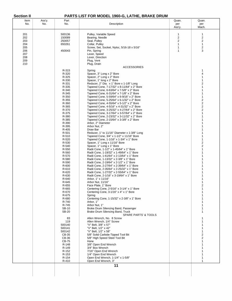
Section II PARTS LIST FOR MODEL 1960-G, LATHE, BRAKE DRUMItem Ass'y. Part Quan. Quan.No. No. No. Description per per
Ass'y. Mach.
201 500136 Pulley, Variable Speed 1 1202 150089 Bearing, Needle 2 2203 250057 Seal, Pulley 2 2204 650261 Collar, Pulley 1 1205 Screw, Set, Socket, Nyloc, 5/16-18 x 5/16" 1 2206 450043 Pin, Spring 1 3207 Lever, Speed208 Lever, Direction209 Plug, Vent210 Plug, Drain
ACCESSORIESR-315 Spring 1R-320 Spacer, 3" Long x 2" Bore 4R-325 Spacer, 2" Long x 2" Bore 1R-330 Spacer, 1" long x 2" Bore 1R-331 Reducer, 2" Dia. x 1" Bore x 1-1/8" Long 2R-335 Tapered Cone, 7-17/32" x 8-11/64" x 2" Bore 1R-340 Tapered Cone, 6-63/64" x 7-5/8" x 2" Bore 1R-345 Tapered Cone, 6-31/64" x 7-1/8" x 2" Bore 1R-350 Tapered Cone, 5-59/64" x 6-9/16" x 2" Bore 1R-355 Tapered Cone, 5-25/64" x 6-1/32" x 2" Bore 2R-360 Tapered Cone, 4-55/64" x 5-1/2" x 2" Bore 2R-365 Tapered Cone, 4-5/16" x 4-31/32" x 2" Bore 2R-370 Tapered Cone, 3-25/32" x 4-27/64" x 2" Bore 2R-375 Tapered Cone, 3-17/64" x 3-57/64" x 2" Bore 1R-380 Tapered Cone, 2-23/32" x 3-11/32" x 2" Bore 1R-385 Tapered Cone, 2-15/64" x 3-3/8" x 2" Bore 1R-390 Arbor, 2" Diameter 1R-395 Arbor Nut, 2" 1R-405 Draw Bar 1R-501 Reducer, 1" to 11/16" Diameter x 1-3/8" Long 1R-510 Tapered Cone, 3/4" x 1-1/2" x 11/16" Bore 1R-520 Tapered Cone, 1-1/16" x 1-3/4" x 1" Bore 1R-530 Spacer, 1" Long x 11/16" Bore 2R-540 Spacer, 1" Long x 1" Bore 2R-550 Radii Cone, 1-1/2" x 1-45/64" x 1" Bore 1R-560 Radii Cone, 1-19/32" x 1-49/64" x 1" Bore 1R-570 Radii Cone, 1-61/64" x 2-13/64" x 1" Bore 1R-580 Radii Cone, 1-13/32" x 2-3/8" x 1" Bore 1R-590 Radii Cone, 2-19/64" x 2-1/2" x 1" Bore 1R-600 Radii Cone, 2-27/64" x 2-39/64" x 1" Bore 1R-610 Radii Cone, 2-35/64" x 2-25/32" x 1" Bore 1R-620 Radii Cone, 1-27/32" x 2-55/64" x 1" Bore 1R-630 Radii Cone, 2-1/16" x 3-19/64" x 1" Bore 1R-640 Arbor, 1" x 11/16" 1R-645 Arbor Nut, 11/16" 1R-655 Face Plate, 1" Bore 2R-665 Centering Cone, 2-5/16" x 3-1/4" x 1" Bore 1R-670 Centering Cone, 3-1/16" x 4" x 1" Bore 1R-675 Spring 1R-680 Centering Cone, 1-15/32" x 2-3/8" x 1" Bore 1R-740 Arbor, 1" 1R-745 Arbor Nut, 1" 1SB-10 Broke Drum Silencing Band, Passenger 1SB-20 Brake Drum Silencing Band, Truck 1
SPARE PARTS' & TOOLS83 Allen Wrench, No. 8 Screw 1
119 Allen Wrench, 1/4" Screw 1500140 "V" Belt, 3/8" x 57" 1500141 "V" Belt, 1/2" x 42" 1500142 "V" Belt, 1/2" x 58" 1CB-35 5/8" Solid Carbide-Tipped Tool Bit 2CB-36 5/8" High Speed Steel Tool Bit 2CB-75 Hone 1R-148 3/8" Open End Wrench 1R-149 3/4" Box Wrench 1R-152 7/16" Open End Wrench 1R-153 1/4" Open End Wrench 1R-154 Open End Wrench, 1-1/4" x 1-5/8" 1R-410 Open End Wrench, 3" 1
11

APPENDIX
BASIC ISSUE ITEMS LIST
Section I. INTRODUCTION
1. GeneralThis appendix is a list of basic issue items. It is
composed of those items which make up the major enditem of equipment and the operator's tools andequipment that are issued with the equipment and arerequired for stockage.
2. Requisition Notesa. Repair Part Identified by Federal Stock Number.
(1) If the exact item requisitioned is notfurnished, or if other action is necessary,the exact nature of the action taken by thecommodity command will be indicated bystandard symbols on prescribed forms.
(2) When requisitioning an item, therequesting agency will order the listeditem. However, the commodity commandwill take necessary action to issue theexhaust stock item until stock isexhausted, whether it be an individualitem, kit, set, or assembly.
b. Part to Which FSN Has Not Been Assigned.When requisitioning a C source (local procurement) itemidentified only by a manufacturer's part number, it ismandatory that the following information be furnishedthe supply officer:
(1) Manufacturer's code number (5-digitnumber preceding the colon in thedescriptive column).
(2) Manufacturer's part number (the number,and sometimes letters, following thecolon, ((1) above). Dashes, commas, orother marks must be included exactly aslisted.(3) Nomenclature exactly as listedherein, including dimensions if necessary(4) Name of manufacturer of end item(from cover of TM or manufacturer'sname plate).
(5) Federal stock number of end item (fromTM).
(6) Manufacturer's model number (from TMor name/data plate, preferably name/dataplate).
(7) Manufacturer's serial number (fromname/data plate).
(8) Any other information such as type, framenumber, and electrical characteristics, ifapplicable.
(9) If DD Form 1348 is used, fill in all blocksexcept 4, 5, 6, and remarks field, inaccordance with AR 725-50. Completeform as follows:
(a) In blocks 4, 5, and 6, listmanufacturer's code and manu-facturer's part number (as listed indescription column).
(b) In remarks field, list noun name(repair part), end item application(FSN of end item), manufacturer,model number (end item), serialnumber (end item), and any otherpertinent information such as framenumber, type, etc.
3. Explanation of Columnsa. Source, Maintenance, and Recoverability Code
(col 1).(1) Materiel numerical codes (col 1a). Not required.(2) Source (col lb). This column indicates the selectionstatus and source for the listed item. Source code usedin this list is-
Code ExplanationC..........Obtain through local procurement.
If not obtainable from localprocurement, requisitionthrough normal supply channelswith a supporting statement ofnonavailability from localprocurement.
(3) Maintenance level (col 1c). This columnindicates the category of maintenanceauthorized to install the listed item.Maintenance level code used in this list is-
Code ExplanationO ..........Organizational maintenance.
(4) Recoverability (col 1d). This columnindicates whether unserviceable itemsshould be returned for recovery orsalvage. When no code is indicated, theitem will be considered expendable.Recoverability code used in this list is-
TAGO 8756-A15

Code ExplanationR .........Items which are economically
repairable at direct and generalsupport maintenance activitiesand are normally furnished bysupply on an exchange basis.
b. Federal Stock Number (col 2). This columnindicates the Federal stock number has been assignedby the Cataloging Division, Defense Logistics ServicesCenter.
c. Description (col 3). This column indicates theFederal item name (shown in capital letters) and anyadditional description required for supply operations.The manufacturer's code and part number are alsoincluded for reference.
Code Explanation57127...........Star Machine & Tool
Company.
d. Unit of Issue (col 4). This column indicates thequantity to be requisitioned.
e. Quantity Authorized (col 5). This columnindicates the quantity of the listed item authorized forstockage to constitute the prescribed load.
4. Abbreviations and Symbols
a. Abbreviations.
Abbreviations Explanationc ......................................cycle(s)cire ..................................circumferencedeg ..................................degree(s)fl .....................................flat
Abbreviations Explanation
hdl ...................................handle(d) (s)hd ....................................headHSS.................................high speed steelmin ..................................minimummtd ..................................mountednom .................................nominalo/a ...................................overallsgle-ph.............................single phasev ......................................volt(s)w......................................wide, widthw/.....................................with
b. Symbols.
Symbols Explanationx .......................................by(2 x 4)
5. Suggestions and Recommendations
The direct reporting by the individual user, oferrors, omissions, and recommendations for improvingthis manual, is authorized and encouraged. DA Form2028 (Recommended Changes to DA Publications) willbe used for reporting these improvements. This formwill be completed in triplicate using pencil, pen, ortypewriter. The original and one copy will be forwardeddirect to Commanding General, Headquarters, U.S.Army Weapons Command, ATTN: AMSWE-SMM-P,Rock Island Arsenal, Rock Island, Ill. 61202. Oneinformation copy will be provided to the individual'simmediate supervisor (e.g., officer, noncommissionedofficer, supervisor, etc,).
TAGO 8756-A
16

Section II. BASIC ISSUE ITEMS LIST
(1) (2) (3) (4) (5) (6)Source,
maint. and Federal Illustrationrecov. code stock No. Description
(a) (b) (c) (d) Unit Qty (a) (b)Mat. Sour. Maint Recov. of auth Fig. Itemcode issue No. No.
MAJOR COMBINATIONThe following item is to be requisitioned for
initial use only.R 4910-516-6192 LATHE,BRAKE DRUM: floor mtd, 60 in. rated ea
swing, 25 in. max drum dia, 9 in. min drumdia, w/grinding provisions, 1 hp drive motor,1/2 hp grinding motor, 115-v, 60 c, sgle-ph(57127:1960).
COMPONENTS OF MAJOR COMBINATION
None authorized.
SPARE PARTS
None authorized.
REPAIR PARTS
C O ........................................ BELT, V: rubberized fabric, 57 outside circ, 3/8 ea 1 1 16top w (57127:500140).
C O ........................................ BELT, V: rubberized fabric, 42 outside circ, 1/2 ea 1 1 23top w (57127:500141).
C O ........................................ BELT, V: rubberized fabric, 58 outside circ, 1/2 ea 1 1 27top w (57127:500142).
........................................ TOOLS AND EQUIPMENT FOR:
........................................ LATHE, BRAKE DRUM: (57127:1960)
C O ........................................ ARBOR, DRUM: 1 in. dia, 1 in. thd (57127:R- ea 1 1 15760).
C O ........................................ ARBOR, DRUM: 1 in. dia, 11/16 thd (57127:R- ea 1 1 34640).
C O ........................................ ARBOR, DRUM: 2 in. dia, 2 in. thd (57127:R- ea 1 1 1390).
C O ........................................ BAND, BRAKE DRUM SILENCING: passen- ea 1 1 9ger car (57127:SB-10).
C O ........................................ BAND, BRAKE DRUM SILENCING: truck ea 1 1 8.................(57127:SB-20).
C O ........................................ BAR, DRAW: arbor holding (57127:R-405) ....... ea 1 1 2C O ........................................ CONE, CENTERING: 1 15/32 x 2 3/8 x 1 bore ea 1 1 58
.................(57127:R-680).C O ........................................ CONE, CENTERING: 2 15/16 x 3 1/4 x 1 bore ea 1 1 53
.................(57127:R-665).C O ........................................ CONE, CENTERING: 3 1/16 x 4 x 1 bore (57127: ea 1 1 55
R-470).
TACO 8756A
17

(1) (2) (3) (4) (5) (6)Source,
maint. and Federal Illustrationrecov. code stock No. Description
(a) (b) (c) (d) Unit Qty (a) (b)Mat. Sour. Maint Recov. of auth. Fig. Itemcode issu
eNo. No.
TOOLS AND EQUIPMENT FOR-Cont.LATHE, BRAKE DRUM: (57127:1960)-Cont.
C O ...................................... CONE, RADII: 1 13/32 x 2 3/8 x 1 bore (57127:R- ea 1 1 37580).
C O ...................................... CONE, RADII: 1 1/2 x 1 45/64 x 1 bore (57127:R- ea 1 1 38550).
C O ...................................... CONE, RADII: 1 19/32 x 1 49/64 x 1 bore (57127:R- ea 1 1 39560).
C O ...................................... CONE, RADII: 1 27/32 x 2 55/64 x 1 bore (52727:R- ea 1 1 41620).
C O ...................................... CONE, RADII: 1 61/64 x 2 13/64 x 1 bore (57127:R- ea 1 1 42570).
C O ...................................... CONE, RADII: 2 1/16 x 3 19/64 x 1 bore (57127:R- ea 1 1 43630).
C O ...................................... CONE, RADII: 2 19/64 x 2 1/2 x 1 bore (57127:R- ea 1 1 40590).
C O ...................................... CONE, RADII: 2 27/64 x 2 39/64 x 1 bore (57127:R- ea 1 1 44600).
C O ...................................... CONE, RADII: 2 35/64 x 2 25/64 x 1 bore (57127:R- ea 1 1 52610).
C O ...................................... CONE, TAPERED: 3/4 x 1 1/2 x 1 bore (57127: ea 1 1 28R-510).
C O ...................................... CONE, TAPERED: 1 1/16 x 1 3/4 x 1 bore (57127: ea 1 1 29R-520).
C O ...................................... CONE, TAPERED: 2 15/64; x 3 3/8 x 2 bore(57127: ea 1 1 13R-385).
C O ...................................... CONE, TAPERED: 2 23/64 x 3 11/32 x 2 bore(57127: ea 1 112
R-380).C O ...................................... CONE, TAPERED: 3 17/64x 3 52/64x 2 bore (57127: ea 1 1 6
R-375).C O ...................................... CONE, TAPERED: 3 25/32 x 4 27/64x 2 bore (57127: ea 2 125
R-370).C O ...................................... CONE, TAPERED: 4 5/16 x 4 31/32x 2 bore (57127: ea 2 1 18
R-365).C O ...................................... CONE, TAPERED: 4 55/64 x 5½ x 2 bore (57127: ea 2 1 11
R-360).C O ...................................... CONE, TAPERED: 5 25/64 x 6 9/16 x 2 bore (57127: ea 2 1 5
R-355).C O ...................................... CONE, TAPERED: 5 59/64 x 6 9/16 x 2 bore(57127: ea 1 1 24
R-350).C O ...................................... CONE, TAPERED: 6 31/64 x 7 1/8x 2 bore (57127: ea 1 1 17
R-345).C O ...................................... CONE, TAPERED: 6 63/64 x 7 5/8x 2 bore (57127: ea 1 1 10
R-340).C O ...................................... CONE, TAPERED: 7 17/64 x 8 11/61 x 2 bore (57- ea 1 1 4
127: R-335).C O ...................................... HONE, SHARPENING: tool bit (57127:CB-75)_ ea 1 1 32C O .................5120-224-2504 KEY, SOCKET HEAD SCREW: hex type, ea 1 1 50
L-hdl, 5/64 across fl, 1 7/8 nom Ig arm Ig.C O .................5120-240-5292 KEY, SOCKET HEAD SCREW: hex type, ea 1 1 49
L-hdl, 1/8 across fl, 2 1/4 nom Ig arm Ig.
TAGO 8756A18

(1) (2) (3) (4) (5) (6)Source,
maint. and Federal Illustrationrecov. code stock No. Description
(a) (b) (c) (d) Unit Qty (a) (b)Mat. Sour. Maint Recov. of auth Fig. Itemcode issue No. No.
TOOLS AND EQUIPMENT FOR-Cont.LATHE, BRAKE DRUM: (57127:1960)-Cont.
C O ........................................ NUT, ARBOR: 11/16 thd (57127:R-645)................ ea 1 1 35C O ...................................... NUT, ARBOR: 1 in. thd (57127:R-745).................. ea 1 1 22C O ...................................... NUT, ARBOR: 2 in. thd (57127:R-395).................. ea 1 1 3C O ...................................... PLATE, FACE: 1 in. bore (57127:R-655) ea 2 1 19C O ...................................... REDUCER: 1 in. od to 11/16 id, 1 3/8 Ig (57127:R- ea 1 1 57
501).C O ...................................... REDUCER: 2 in. od to 1 in. id, 1 1/8 Ig (57127:R- ea 2 1 26
331).C O ...................................... SPACER, ARBOR: 11/16 bore, 1 in. Ig (57127:R- ea 2 1 33
530).C O ...................................... SPACER, ARBOR: 1 in, bore, 1 in. Ig (57127:R- ea 2 1 36
540).C O ...................................... SPACER, ARBOR: 2 in. bore, 1 in. Ig (57127:R- ea 1 1 21
330).C O ...................................... SPACER, ARBOR: 2 in. bore, 2 in. Ig (57127:R- ea 1 1 20
325).C O ...................................... SPACER, ARBOR: 2 in. bore, 3 in. Ig (57127:R- ea 4 1 14
320).C O ...................................... SPRING, COIL: 4 coil, 2 3/8 od (57127:R-315) ea 1 1 7C O ...................................... SPRING, COIL: 4 coil, 2 3/8 id tapered to 1½ id ea 1 1 56
(57127:R-675).C O ...................................... TOOL BIT: 5/8 sq, carbide tipped (57127:CB-35). ea 2 1 30C O ...................................... TOOL BIT: 5/8 sq HSS (57127:CB-36).................. ea 2 1 31C O ...............5120-293-1266 WRENCH, BOX: stght, sgle-hd type, hex shape ea 1 1 45
wrench opng, 3/4 opng, 4 3/8 nom o/a Ig (57127:R-149).
C O ...............5120-293-2124 WRENCH, OPEN END, FIXED: dble-hd ea 1 1 51type, 15 deg angle of hd, engineer style, 1 1/4and 1 5/8 wrench opngs, 14 nom o/a Ig, 9/16 thkof hd (57127:R-154).
C O ...............5120-293-1840 WRENCH, OPEN END, FIXED: sgle-hd type, ea 1 1 4815 deg angle of hd, 1/4 wrench opng, 3½ nomo/a Ig, 3/16 thk hd (57127:R-153).
C O ...............5120-277-1261 WRENCH, OPEN END, FIXED: sgle-hd type, ea 1 1 4715 deg angle of hd, 3/8 wrench opng, 3 7/8 nomo/a Ig, 17/64 thk hd (57127:R-148).
C O ...................................... WRENCH, OPEN END, FIXED: sgle-hd type, ea 1 1 4615 aeg angle of hd, 7/16 wrench opng (57127:R-152).
C O ...................................... WRENCH, OPEN END, FIXED: sgle-hd type, ea 1 1 5415 deg angle of hd, 3 wrench opng, 17 nomo/a Ig (57127:R-410).
TAGO 8756-A
19

Figure 1. Tools and equipment.TAGO 8756-A
¶ U.S. GOVERNMENT PRINTING OFFICE : 1985 0 - 461-421 (20652)
20

SECTION II
FIG. 2-1. PARTS BREAKDOWN MODEL 196013


PIN: 006042-000

This fine document...
Was brought to you by me:
Liberated Manuals -- free army and government manuals
Why do I do it? I am tired of sleazy CD-ROM sellers, who take publicly available information, slap “watermarks” and other junk on it, and sell it. Those masters of search engine manipulation make sure that their sites that sell free information, come up first in search engines. They did not create it... They did not even scan it... Why should they get your money? Why are not letting you give those free manuals to your friends?
I am setting this document FREE. This document was made by the US Government and is NOT protected by Copyright. Feel free to share, republish, sell and so on.
I am not asking you for donations, fees or handouts. If you can, please provide a link to liberatedmanuals.com, so that free manuals come up first in search engines:
<A HREF=http://www.liberatedmanuals.com/>Free Military and Government Manuals</A>
– SincerelyIgor Chudovhttp://igor.chudov.com/
– Chicago Machinery Movers