operator’s manual mill automation kit - versabuilt robotics
TRANSCRIPT

Mill Automation Kit Operator’s Manual
Copyright VersaBuilt 2021
Section 1 Safety Warnings
Section 2 Selecting Pneumatic Automatic vs Manual Mode
Section 3 Accessing VSC Home Screen and Navigation
Section 4 Running Jobs and Aligning Parts in the Visual Infeed System
Section 5 Recovery Panel
Section 6 IO Panel, Calibration and About Page
Section 7 Cleaning and Maintenance
Appendix A Hand Loading and Unloading MultiGrip Jaws
Appendix B Bin Drop Option
Appendix C Home Locations
Table of Contents
Table of Contents

DANGER: VersaBuilt makes industrial machine tool automation components designed to be operated by trained personnel only. Machine tool automation components may move suddenly and without warning. Serious or fatal crushing injuries can occur from contact with the robot, gripper or vises.
Before deploying VersaBuilt industrial machine tool automation components, a safety risk assessment must be completed in accordance with local, state and/or federal requirements.
VersaBuilt industrial machine tool automation components should only be used by trained operators.
Read and understand the VersaBuilt Mill Automation Kit Safety Manual before proceeding
Safety Warnings
Section 1: Safety Warnings

Selecting Pneumatic Automatic vs Manual ModeSection 2

Selecting Automatic vs Manual Mode
The Mill Automation Kit has 2 pneumatic modes: Auto and Manual
• Auto mode is for running parts in the CNC with robotic tending
• Manual mode is for running parts in the CNC via hand loading
When the system is in Auto Mode, air to the hand valves on the CNC table is blocked.
When the system is in Manual Mode, air to the VSC Mill Panel is blocked, disabling automatic functionality.
Switching between these 2 modes is done by way of the Diverter Valve and the Vise Hand Valves
Diverter Valve shown in “Auto-Mode”
Section 2: Selecting Automatic vs Manual Mode

Setting Automatic Mode:
1. Be prepared for sudden movement and keep all body parts away from the vises gripper, door opener and/or VersaBlast when moving the Diverter Valve switch
2. Set each Vise Hand Valve to the center position
3. Ensure all persons are clear of the vises, gripper, door opener and VersaBlast
4. Move the Diverter Valve handle to the AUTO position
5. From the VSC Recovery panel, verify the vises are opening and closing correctly
Selecting Pneumatic Automatic vs Manual Mode
Diverter Valve shown in “Auto-Mode”
Vise Hand Valves shown in center
position
Section 2: Selecting Automatic vs Manual Mode

Setting Manual Mode:
1. Be prepared for sudden movement of the vises, gripper, door opener and/or VersaBlast
2. Ensure all persons are clear of the vises, gripper, door opener and VersaBlast
3. From the VSC Recovery panel, press the Float Vises button
4. Move the Diverter Valve handle to the MANUAL position
5. With ALL body parts clear of each vise, set each Vise Hand Valve away from the center position
Selecting Pneumatic Automatic vs Manual Mode
Diverter Valve shown in “Manual-Mode”
Note: When MultiGrip OD Jaws are in the Robot Gripper and the diverter valve is shifted to Manual position, the Jaws will SPRING OPEN releasing any clamped material
Section 2: Selecting Automatic vs Manual Mode

Accessing VSC Home Screen and NavigationSection 3

Accessing the VersaBuilt System Controller
The VSC can be accessed by any computer, tablet or phone with WiFi or Ethernet using a web browser such as Google Chrome.
VersaBuilt recommends dedicating a laptop computer or a full-sized tablet (10” or greater) such as an IPad.
The VSC can be accessed via a smartphone or small tablet, with some changes to how the user interface is displayed.
Section 3: Accessing VSC Home Screen and Navigation

Accessing the VersaBuilt System Controller (VSC)
Connecting to the VSC via Ethernet
For an Ethernet device such as a laptop, plug the device into an available port on the Ethernet switch the VSC is plugged into. Go to the device’s Ethernet settings and configure the Ethernet port to:
DHCP: Manual, disabled or do not automatically assign addressIP Address: 192.168.2.5Subnet Mask: 255.255.255.0 Default Gateway: 192.168.2.1DNS: 8.8.8.8
Connecting to VSC via VSC Wifi Access Point
For a Wifi connected device such as an IPad, device network settings will be automatic. Open your device’s Wifi settings and search for a network named vscXXXXX where the XXXXX is the serial number of your VSC (e.g., vsc00125).
Configure your device’s Wifi settings to turn off settings that allow the device to automatically join networks or hot spots.
Section 3: Accessing VSC Home Screen and Navigation
Using the VSC on Smartphones and Small Tablets
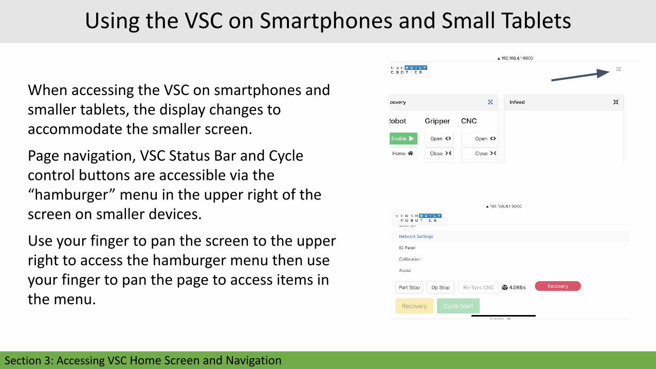
When accessing the VSC on smartphones and smaller tablets, the display changes to accommodate the smaller screen.
Page navigation, VSC Status Bar and Cycle control buttons are accessible via the “hamburger” menu in the upper right of the screen on smaller devices.
Use your finger to pan the screen to the upper right to access the hamburger menu then use your finger to pan the page to access items in the menu.
Section 3: Accessing VSC Home Screen and Navigation

Robot-Specific VSC Configuration
Some robots require a VersaBuilt program to be run on the robot’s teach pendant or the robot to be put in a special mode for the VSC to be able to control the robot.
Check the VersaBuilt Robot Installation, Configuration and Operation manual that matches your robot make and model for additional steps required to enable operation with the VSC.
Section 3: Accessing VSC Home Screen and Navigation

VersaBuilt System Controller Home Screen
Section 3: Accessing VSC Home Screen and Navigation

VSC Status Bar
Navigation - allows navigation between the available VSC Pages
Part Stop will pause after current part is complete, Op Stop will pause after current CNC op
Robot Payload: current payload of the robot, click on the payload to change the payload
Re-Sync CNC: if an error occurs on the CNC during the processing of the job, the Re-Sync CNC button allows the system to continue processing. Pressing the Re-Sync CNC allows the operator to choose to re-run the current CNC operation or continue as if the current CNC operation has completed successfully.
Processing Mode - the processing mode of the VSC system; one of Running, Paused, Recovery or Idle
Control Buttons:● Cycle Start: when Processing Mode is Idle and job is configured, begins processing● Pause Next: when Processing Mode is Running, pauses robot motion after current motion
commands are complete● Recovery: Enters Recovery Mode
Section 3: Accessing VSC Home Screen and Navigation
Actions Panel
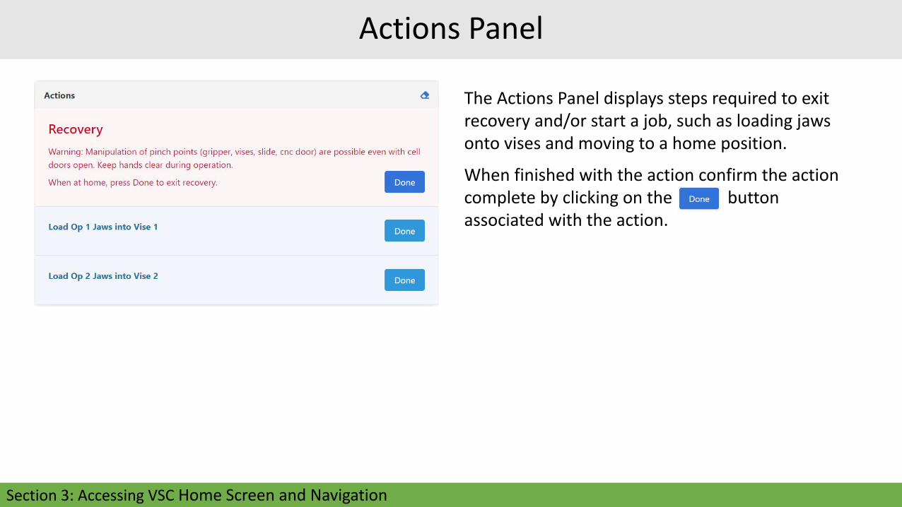
The Actions Panel displays steps required to exit recovery and/or start a job, such as loading jaws onto vises and moving to a home position.
When finished with the action confirm the action complete by clicking on the button associated with the action.
Section 3: Accessing VSC Home Screen and Navigation

Job Panel and Activity Monitor
The Job Panel allows the operator to select a part
configuration and a part count and load a job for processing
Remaining displays how many parts remain and Completed
shows how many parts have completed for the current Job
The Activity Monitor shows what the VSC is currently doing
or what step the VSC is waiting to complete before
additional processing
Section 3: Accessing VSC Home Screen and Navigation

Running Jobs and Aligning Parts in the Visual Infeed SystemSection 4

Section 4: Running Jobs and Aligning Parts in the Visual Infeed System
Running a Job on the VSC

To run a job on the VSC, begin by selecting the
Part from the drop-down list in the Job Panel.
The operator will be prompted in the Actions
panel to load the jaws into the vises.
Enter a Count of parts to be processed in the
job.
Press the button to initialize the raw
material in the infeed display.
Running a Job on the VSC
Section 4: Running Jobs and Aligning Parts in the Visual Infeed System

After the Part is selected in the Job panel, the Infeed
panel will display an outline of each part in the Visual
Infeed showing the alignment of the raw material on the
table.
After the Load button is pressed in the Actions panel, the
Infeed panel will show the operator where to load the
raw material by displaying the allocated parts in purple.
Part locations outlined in a solid line show that parts
picked and placed in these locations will have the far end
of MultiGrip jaws pointing away from the robot; part
locations outlines in a dashed line will have the far end
of the MultiGrip jaws pointing towards the robot.
Running a Job on the VSC
Section 4: Running Jobs and Aligning Parts in the Visual Infeed System

Infeed Panel
Rectangles that are white are unassigned, rectangles that are purple are raw material registered as loaded with the VSC, rectangles that are maroon are currently being processed, rectangles that are green are completed parts.
The Actions Panel will include an action to remove completed (green) parts. Remove the completed parts then press the Done button in the Actions panel and the green rectangles will become white signaling to the VSC that those locations are available to load more raw material.
Section 4: Running Jobs and Aligning Parts in the Visual Infeed System

Infeed Panel - Click Menu
Clicking on a colored slot when not in Recovery mode will bring up a pop-up menu with an option for Clear. if the Clear menu item is selected, the rectangle will turn white signifying to the VSC that raw material is no longer loaded in that location and the part count will reduce by one and
Clicking on a white rectangle will bring up a pop-up menu with an option for Load. Clicking on Load will load a single part (turning the rectangle purple) at that location.
Section 4: Running Jobs and Aligning Parts in the Visual Infeed System

Before pressing the Cycle Start button on the VSC, the following
conditions must be met:
● MultiGrip jaws for the job loaded in the CNC vises, action
panel items acknowledged
● Raw material loaded and aligned in the Visual Infeed
● CNC in Memory mode and Idle state
● Proper CNC program selected:
● 9000 program for Haas and Fanuc
● vbDispatcher running on Okuma
● Correct program selected for Generic
● Pneumatic Selector Valve in the Auto position, vise hand
valves in the center position
● VSC Enable button needs to be pushed before pressing VSC
CycleStart button on screen (VSC Enable valid for 3 minutes)
Running a Job on the VSC
Section 4: Running Jobs and Aligning Parts in the Visual Infeed System

The VersaBuilt Visual Infeed System is a grid
pattern engraved into the robot’s part
infeed area.
By following a few simple rules, an operator
is able to quickly and accurately place parts
in the infeed area while maximizing the
total part storage capacity across a wide
range of part sizes.
Aligning Parts Using the Visual Infeed System
Section 4: Running Jobs and Aligning Parts in the Visual Infeed System

1.5” min gap between parts in X direction
The upper left edge of the grid is the initial
index point - the first part will always be located
in the upper left corner of the visual grid.
Top and left edge of a part are always aligned
with the grid lines.
Parts are allocated left to right in the positive X
direction and then positive Y direction.
At the start of a job, the VB Mill Process
program will provide part spacing information
to the operator.
The minimum spacing between parts in the X
direction is 1.5” and in the Y direction is 0.25”.
Aligning Parts Using the Visual Infeed System
First Part Second Part
1 2 3 4 5
6 7 8 9 10
Align part left and top edges to the cart grid lines shown in the Infeed Panel of the VSC
Positive Y D
irection
Positive X Direction
Section 4: Running Jobs and Aligning Parts in the Visual Infeed System

Column spacing allows room for the MultiGrip Jaw pocket sidewall and the maximum opening travel of the MultiGrip FJ Gripper.
The maximum suggested MultiGrip Jaw pocket sidewall is 0.75” - see the Mill Automation Kit - Machinist Manual for more information on MultiGrip Jaw design.
Aligning Parts Using the Visual Infeed System
Section 4: Running Jobs and Aligning Parts in the Visual Infeed System

Aligning Parts Using the Visual Infeed System
Part Width 0 to 0.5” >0.5” to 2” >2” to 4” >4” to 6” >6” to 8” >8” to 10”
X Spacing Inches 2” 4” 6” 8” 10” 12”
X Spacing Columns 1 2 3 4 5 6
Infeed X Spacing Chart
Section 4: Running Jobs and Aligning Parts in the Visual Infeed System

Aligning Parts Using the Visual Infeed System
Part Length
0” to 1.5”
>1.5” to 3.5”
> 3.5” to 5.5”
> 5.5” to 7.5”
> 7.5” to 9.5”
> 9.5” to 11.5”
Y Spacing Inches 2” 4” 6” 8” 10” 12”
Y Spacing Rows 1 2 3 4 5 6
Infeed Y Spacing Chart
Section 4: Running Jobs and Aligning Parts in the Visual Infeed System

Recovery PanelSection 5

Section 5: Recovery Panel
Recovery Panel
The Recovery Panel can be accessed at any time by pressing Recovery button in the top right of the screen.
The VSC will enter the Recovery state whenever a processing error is encountered.
When in Recovery with an active job, the Recovery Panel can be used to get the Mill Automation Kit and CNC in state where the job can be resumed.
When in Recovery without a job active, the Recovery panel can be used to perform individual robot actions useful for validating new part processes.
Before using the Recovery panel functions, the Operator will be prompted to press the Cycle Start button to acknowledge they are physically present and the system is safe to operate.

Recovery Panel
Robot allows the robot to be Enabled for movement, Paused, Reset or Moved to the Home Position
The Home button can be used to get the robot to a safe Home position from almost anywhere (The robot must be at the Home position to exit the Recovery Panel)
Gripper allows the MultiGrip Gripper to be opened, closed or floated; the Float button removes open or closing pressure from the gripper
CNC allows the operator to open or close the CNC Door (for VSC Controlled door openers only) and check the connection status with the CNC (VSC Macro CNC Drivers only)
Section 5: Recovery Panel

Home Locations
The Mill Automation Kit has pre-defined locations that every operation either starts from, ends at or uses during processing. Before processing can begin, the robot must be in a known home location. If the robot is not at a recognized home location at the start of processing, an error will occur and the system will go into Recovery mode.
Press the Home button in the Recovery Panel to move the robot to its default Home location, CNC Home Home. If the robot does not recognize its current location as a Home location, the VSC will prompt the operator to select the Home location the robot is currently nearest to. The robot’s first move will be to the Home location selected, from there the robot will know how to get to the Table Home location.
NOTE: Failure to understand which Home location the robot is nearest to could result in the robot colliding with the CNC or other things in its path.
A complete list of all Home locations is provided in Appendix C.
Table Home Location
Section 5: Recovery Panel

Recovery Infeed Panel - Click Menu
While in Recovery mode, clicking on a white rectangle will bring up a pop-up menu with an option to Pick/Place. Selecting Pick/Place will bring up a pop-up window giving an option to test Pick or Place a part at that location in the Infeed.
To begin, the robot must be at a known Home location (see Appendix C) and the jaws (jaws and part for Place) must be held by the Robot. Enter the Pick/Place Height, Jaw Weight and Part Weight then press the Pick or Place button as desired.
Section 5: Recovery Panel

Recovery Panel - Vise
Vise Open button opens the vise
Vise Close button closes the vise
Unload button uses the robot to unload MultiGrip Jaws from the vise and
move to a home position
Load button uses the robot to load MultiGrip Jaws from the vise and move to
a home position.
Section 5: Recovery Panel

Recovery Panel - Vise Unload
Clicking on the Unload button will pop up the Vise Unload panel.
Enter the jaw and part parameters to load the vise. The vise must be holding the jaws or the jaws and a part before starting the Vise Unload.
If Unload Type Jaws is selected, the robot will unload the jaws from the vise. If Unload Type Part is selected, the robot will invert the jaws over the vise and unload the part the jaws stored on the vise; the vise must be holding the jaws and part needed to unload the part before starting the Part Unoad.
Section 5: Recovery Panel

Recovery Panel - Vise Load
Clicking on the Load button under each Vise in the Recovery Panel will pop up the Vise Load panel.
Enter the jaw and part parameters to load the vise. The robot must be holding the jaws or the jaws and a part before starting the Vise Load.
If Load Type Jaws is selected, the robot will load the jaws into the vise. If Load Type Part is selected, the robot will invert the jaws over the vise and load the part into the vise; the vise must be holding the jaws needed to load the part before starting the Part Load.
Test Load can be used to verify the calibration of the system and that the robot is able to properly place the jaws before clamping.
Section 5: Recovery Panel

Recovery Panel - Vise Load - Test Load
Test Load can be used to verify the calibration of the Mill Automation Kit relative to the CNC and that the robot is able to properly place the jaws. The Test Load function performs Load Vise function up until the vise clamp function. After the Test Load function is executed and the proper position of the jaws is verified, the Test Load Return button will appear. Pressing the Test Load Return button will move the robot out of the vise while remaining ahold of the jaws.
Note: If the robot is not able to properly locate the Jaws before clamping, damage may occur to the jaws when the vise is clamped.
Section 5: Recovery Panel

Extended Recovery Panel
Extended Functions can be accessed in the Recovery Panel by pressing the blue 4 arrows button in the upper right of the Recovery Panel.
The Move To button allows user to select a specific robot home position to move to.
The Extended Recovery Panel also adds Robot Motion Jogging commands and the ability to put the robot into Freedrive mode.
Section 5: Recovery Panel

Extended Recovery Panel - Move Home
Clicking on the button allows user to select robot home positions to move to.
The Nearest Starting Home is where the robot will begin its motion to. The Destination Home is where the robot will finish its motion path.
Refer to Appendix C Home Locations for more information about how to identify what Home Location the robot is nearest to.
Section 5: Recovery Panel

Extended Recovery Panel - Jogging
The movement scale adjusts how far the
robot moves in inches (or millimeters) or
degrees; always start with movements of
1mm (1deg) or less until you are confident in
the direction and distance of motion.
+xyz and -xyz create linear motion relative to
the MultiGrip jaws from the current position.
+rxryrz and -rxryrz rotate the MultiGrip jaws
from the current position.
Section 5: Recovery Panel

Extended Recovery Panel - Enable Freedrive
When Enable Freedrive is selected, a popup window will appear allowing the user to set the payload. Select what the robot is holding (Jaws, Jaws and Part or Empty Gripper) and set the remaining fields to properly set the robot payload.
How Freedrive is ended is robot specific. Refer to the Robot Installation, Configuration and Operation manual that matches your make and model for more information about using Freedrive.
Section 5: Recovery Panel

CNC Processing Errors: Part is Good
If an error occurs during the CNC machining cycle but the part can be successfully processed, press the Re-Sync CNC button.
If the part can be completed by re-running the current milling operation press the Re-Run button and the VSC will re-run the current milling operation for the part and continue processing.
If the operator is able to run the milling operation to completion manually, press the Resume button and the VSC will continue processing as if the milling operation completed successfully.
Note: If using Resume, the CNC must be in the table load position before continuing.
Note: If configured for a CNC Controlled Autodoor, the CNC door must be open before pressing the Resume button.
Recovering from CNC Processing Errors
Section 5: Recovery Panel

CNC Processing Errors: Part is Bad
If an error occurs during the CNC machining cycle and the part cannot be successfully completed, the VSC will need to be put into Recovery mode and the MultiGrip jaws and robot will need to be reset similar to the start of the job.
Start by pressing the Recovery Button. Move the robot to Home using the Home button in the Recovery panel. Clean off the vises with compressed air and remove any parts held in the vises. If the robot is holding jaws, remove the jaws and return the jaws to the appropriate vise.
When all steps are complete, end Recovery mode, and press the VSC Cycle Start button to continue.
Recovering from CNC Processing Errors
Section 5: Recovery Panel

Robot processing errors most commonly occur if the robot collides with something or the robot actual payload differs significantly from the programmed payload. This can occur if the robot fails to pick a part or drops a relatively heavy part. When a robot processing error occurs, the VSC will go into Recovery mode automatically.
Recovering from Robot Processing Errors
The first step is to reset the robot so it is ready to accept commands again from the VSC. Resetting the robot is robot model specific. Refer to the Robot Installation and Operation Manual that matches the robot used in your Mill Automation Kit.
When the robot is reset, move the robot to Home using the Home button in the Recovery panel. Clean off the vises with compressed air and remove any parts held in the vises. If the robot is holding jaws, remove the jaws and return the jaws to the appropriate vise.
When all steps are complete, end Recovery mode, and press the VSC Cycle Start button to continue.
Section 5: Recovery Panel

IO Panel, Calibration and About PageSection 6

Section 6: IO Panel, Calibration and About Page
IO Panel
The VSC IO Panel Page is a dashboard displaying all inputs and outputs configured in the VersaBuilt System Controller.
The dashboard displays high and low settings with buttons to toggle high and low for testing and troubleshooting purposes.
The IO Panel is used to verify the installation and to troubleshoot problems.

The VSC Calibration Page is used to calibrate the Robot Infeed, in-CNC position, VersaBlast position, and Vises.
Pressing the Warmup button will cause the Robot to move over the VersaCart table to warmup the robot joints. If the robot hasn’t been used for more than an hour or the robot is below 60F, VersaBuilt recommends running the warmup cycle several times to ensure that the robot will be accurate.
The VSC Calibration page use is documented in the Mill Automation Kit Installation Manual.
VSC Calibration Page
Section 6: IO Panel, Calibration and About Page

The System Information Panel includes the serial number of the Mill Automation Kit and the software version
The Support Panel includes information about manuals and training videos, VersaBuilt’s support telephone number an option to Enable or Disable remote support over the Internet for a VersaBuilt technical support representative and a button to Restart the VSC.
VSC About Page
Section 6: IO Panel, Calibration and About Page

Cleaning and MaintenanceSection 7

Section 7: Cleaning and Maintenance
Cleaning and Maintenance
Daily Maintenance:
● Lightly dampen a cloth with warm,
soapy water
● Wipe down the robot, gripper and the
VersaCart
● Use a clean dry cloth to remove any
remaining soapy water

Cleaning and Maintenance
Weekly Maintenance:
● Remove the Visual Infeed top by
removing the M6 flat head screws that
hold it in place
● Lightly dampen a cloth with warm,
soapy water
● Wipe down the VersaCart table top
● Use a clean dry cloth to remove any
remaining soapy water
● Wash the Visual Infeed using running
water or a pressure washer
● Once dry, re-install Visual Infeed top
onto VersaCart
Section 7: Cleaning and Maintenance

Cleaning and Maintenance - Robot
Refer to the included robot-specific
Installation, Configuration and Operation
manual for tips on maintenance specific to
your robot type.
Section 7: Cleaning and Maintenance

Appendices
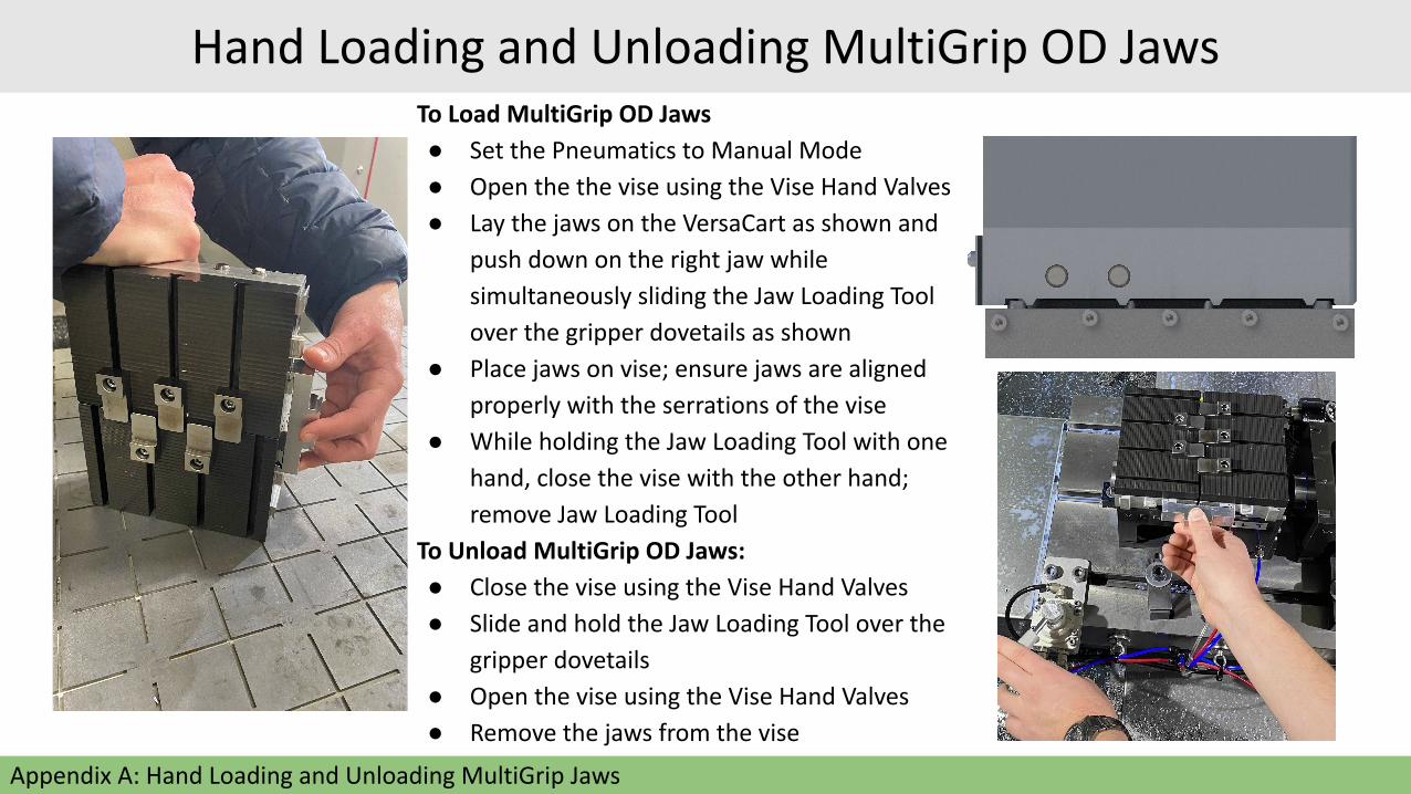
To Load MultiGrip OD Jaws
● Set the Pneumatics to Manual Mode
● Open the the vise using the Vise Hand Valves
● Lay the jaws on the VersaCart as shown and
push down on the right jaw while
simultaneously sliding the Jaw Loading Tool
over the gripper dovetails as shown
● Place jaws on vise; ensure jaws are aligned
properly with the serrations of the vise
● While holding the Jaw Loading Tool with one
hand, close the vise with the other hand;
remove Jaw Loading Tool
To Unload MultiGrip OD Jaws:
● Close the vise using the Vise Hand Valves
● Slide and hold the Jaw Loading Tool over the
gripper dovetails
● Open the vise using the Vise Hand Valves
● Remove the jaws from the vise
Appendix A: Hand Loading and Unloading MultiGrip Jaws
Hand Loading and Unloading MultiGrip OD Jaws

Removing MultiGrip Jaws from the Gripper:
● Unclamp the gripper by going to the Recovery panel
on the VersaBuilt System Controller (VSC) and
selecting Open under Gripper
● For OD jaws, push the jaws together until the dovetail
feature on the jaw can clear the dovetail feature and
the jaws can be pulled away from the gripper
● For ID jaws, pull the jaws apart until the dovetail
feature on the jaw can clear the dovetail feature and
the jaws can be pulled away from the gripper
Hand Loading and Unloading MultiGrip Jaws
Appendix A: Hand Loading and Unloading MultiGrip Jaws

Bin Drop Option
Appendix B: Bin Drop Location
● Place bucket or bin
at location shown
● Protect parts with
foam, water or
other means

Home Positions
Appendix C: Home Locations
In Recovery, when selecting the Move Home button, the system needs to know approximately where the robot is currently located and optionally where the robot is going.
There are 5 primary home positions:
● Table Home● CNC Home● InCNC Home● Bin Drop● VersaBlast
The following pages illustrate these home positions for reference

Default Table Home Position
Robot is oriented above table
Appendix C: Home Locations

CNC Home Position (Default Home Location)
Robot is facing CNC, but not inside CNC
Appendix C: Home Locations

Default In CNC Home Position
Robot is inside CNC, above vises
Appendix C: Home Locations

Default Bin Drop Position
Robot is above Bin Drop location, outside CNC, with
gripper flipped to drop parts
Appendix C: Home Locations

Default VersaBlast Position
Robot is inside CNC, oriented to clean bottom or top of jaws
with VersaBlast
Appendix C: Home Locations

Copyright VersaBuilt 2021