operator’s manual - northern lights · read this operator's manual thoroughly before ... it...
TRANSCRIPT

OPERATOR’S MANUAL
Technicold Marine Systems | www.technicold.com
OT-FX2 OLED TOUCHfor the FX II Touch control panel

Technicold by Northern Lights1419 W. Newport Center DriveDeerfield Beach, FL 33442Tel: (954) 421-1717Fax: (954) 421-1712
Copyright ©2015, Northern Lights, Inc.All rights reserved. Northern Lights, Technicold,the Northern Lights logo, and the Technicold logo are trademarks of Northern Lights, Inc.
Printed in U.S.A.PART NO.: OTFX2

OT-FX2 OLED TOUCH 7/15
1
Read this operator's manual thoroughly before starting to operate your equipment.This manual contains information you will need to run and service your new unit.
TABLE OF CONTENTS ................................................................................... 2INTRODUCTION .............................................................................................. 2OPERATIONS Applying Power .......................................................................................... 3 Screen Saver ............................................................................................. 3 Touch Screen Operation ............................................................................ 3 Control Off .................................................................................................. 3 Control On .................................................................................................. 3 Control Function ......................................................................................... 3 DX and AH Configurations ..................................................................... 3- 4 Operating Modes ....................................................................................... 4 Operating the Fan ...................................................................................... 5 Viewing System Statue (View Mode) ......................................................... 5 Outside Air Temperature ............................................................................ 5 Alternate Air Sensor ................................................................................... 5 Pump Sentry (DX Only) ............................................................................. 6SYSTEMS WITH EASYSTART ........................................................................ 6 Capacitor Selection .................................................................................... 6 Initial Starts ................................................................................................ 6 Forcing EasyStart to Relearn ..................................................................... 6 Additional EasyStart Jumper Usage .......................................................... 7FRESH AIR MAKE UP UNIT (FAMU) .............................................................. 8FAMU SYSTEM OPERATION ......................................................................... 9VIEWING SYSTEM STATUS (FAMU MODE) ................................................ 10JUMPER SETTINGS .......................................................................................11PROGRAMMABLE PARAMETERS .............................................................. 12 Entering the Program Mode ..................................................................... 12 Parameter Descriptions .................................................................... 12 - 15AIR HANDLER (AH) PROGRAMMABLE PARAMETERS TABLE ............... 16DIRECT EXPAINSION (DX) PROGRAMMABLE PARAMETERS TABLE .... 17FRESH AIR MAKE UP UNIT (FAMU) PROGRAMMABLE PARAMETERS TABLE .. 18DC FAN OPTION BOARD ............................................................................. 18FAN ................................................................................................................ 19SPECIFICATIONS .......................................................................................... 20DRAWINGS ............................................................................................. 21 - 24
Table of Contents
Proprietary InformationThis publication is the property of Northern Lights, Inc.
It may not be reproduced in whole or in part without the written permission of Northern Lights, Inc.© Northern Lights, Inc. All right reserved.
Every precaution has been taken in the preparation of this manual to insure its accuracy. However, Technicold by Northern Lights assumes no responsibility for errors and omissions. Neither is any liability assumed for damages
resulting from the use of this product and information contained herein.
Litho U.S.A. Publication number OT-FX2 OLED TOUCH 7/15
OPERATOR'S MANUALfor OTFX2
NOTES: All items labeled COMP should be considered Electric Heater applications.When the Alternate Air Sensor is required the Outside Air Sensor is not available.

OT-FX2 OLED TOUCH 7/15
2
INTRODUCTION
Introduction:
The FXII Touch system is a versatile digital controller configurable for self
contained air conditioning, air handling, and fresh air make up duty.
Features include:
• Easy touch screen operation.
• Built in room temperature sensor.
• The display is compatible with Vimar and Gewiss frames.
• Visual symbols enable the viewer to see the operating status at a glance.
• Easily programmed for customized operation.
• Both automatic and manual six level fan speed adjustment.
• Universal 115/230 VAC 50/60 Hz power supply.
• Built in options for fault protection for low voltage, high current, low Freon
• pressure, and high Freon pressure.
• Selectable de-icing program to prevent evaporator icing.
• Automatic moisture mode provides periodic cabin dehumidification.
Optional features include:
• Outside air temperature sensor.
• Alternate air sensor.
• DC fan control board featuring programmable speed control for up to four quiet DC fans.
• CAN Computer area network capability
• EasyStart compressor start control.
• Fresh Air Makeup Unit provides humidity and temperature control of fresh air.
• Pump sentry sensor for monitoring condenser coil temperature.

OT-FX2 OLED TOUCH 7/15
3
Applying power:When power is first applied, the display will show the software revision, and then return to the last operating mode the unit was in when power was removed.
Screen Saver:In screen saver, the display will appear dim and the information will scroll across the screen. Status symbols appear as needed and operation continues in the mode selected. Screen saver is activated after two minutes without touching the screen in any mode. To exit screen saver, just touch the screen.
Touch Screen Operation:The touch screen is divided into six equal touch areas as shown on the right. Icons are displayed in these areas to indicate the function. Functions are activated by pressing and releasing or pressing and holding the touch area.
Control Off:When the display is in the off mode, the temperature will show in the center of the screen. Press the On/Off symbol in the lower left corner to start the operation of the control.
Control Function:Three basic configurations for this control are Air Handler (AH), Direct Expansion (DX), and Fresh Air Make up Unit (FAMU). Control function is determined by selecting the appropriate settings in the programmable parameters and setting configuration jumpers on the FXII power supply. Specific details of settings can be found throughout this manual.
DX and AH Configuration:Sensor Connections (DX / AH): An alternate air sensor may be installed in the ALT jack on the FXII power supply. This sensor overrides the display mounted ambient air sensor. The sensor is normally installed in the return air stream.
Sensor Connections (DX):An outside air sensor may be connected to the OUTSIDE jack on the FXII power supply. Outside air temperature will alternate with the set point in the upper right corner of the display. A pump sensor may be installed on the condenser coil and connected to the OUTSIDE jack. See Pump Sentry in the programmable parameters section for details
OPERATIONS

OT-FX2 OLED TOUCH 7/15
4
OPERATIONS
Sensor Connections (AH):A loop water sensor must be connected to the OUTSIDE jack on the FXII powersupply.On systems that do not use the alternate air sensor, an outside air sensor may beconnected to the ALT jack on the FXII power supply. Outside air temperature willalternate with the set point in the upper right corner of the display. Set the “Alt AirEnabled” programmable parameter to use this feature.DX and AH Operation:
Operating Modes:Four operating modes are available and can be changed by pressing the symbol inthe upper left corner. The symbols below will appear in the upper left on the display.
Automatic mode will change the system from cooling to heating or from heatingto cooling as necessary. Once you have selected the mode, set the desired roomtemperature by pressing the set point in the upper right corner. Use the arrows to raise orlower the set point and press X when you are finished.Moisture mode is used to help control humidity in the room while the room isunoccupied. The control will operate in cooling mode for up to 1 hour every 6 hours.Manual fan speed selection is not available in this mode.
OT-FX2 OLED TOUCH 7/15
5
OPERATIONS
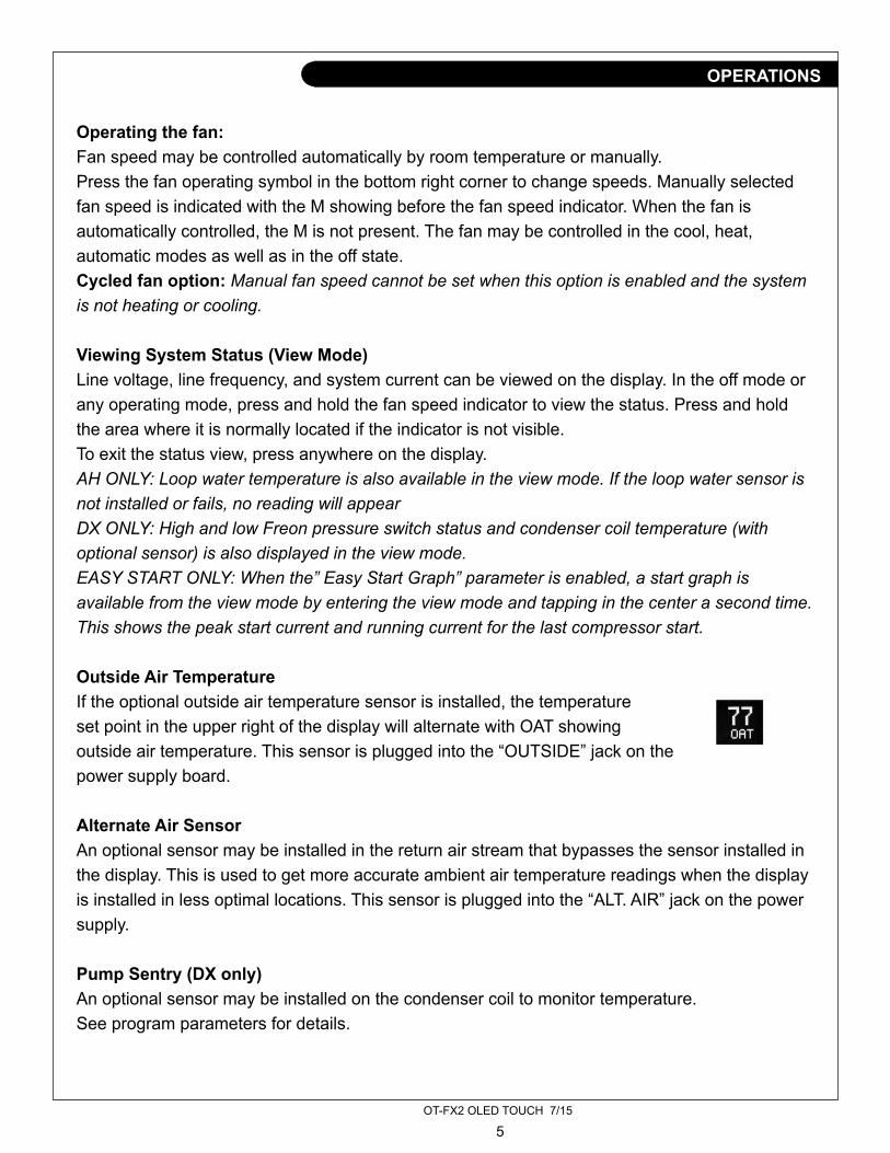
Operating the fan:Fan speed may be controlled automatically by room temperature or manually.Press the fan operating symbol in the bottom right corner to change speeds. Manually selected fan speed is indicated with the M showing before the fan speed indicator. When the fan is automatically controlled, the M is not present. The fan may be controlled in the cool, heat, automatic modes as well as in the off state.Cycled fan option: Manual fan speed cannot be set when this option is enabled and the system is not heating or cooling.
Viewing System Status (View Mode)Line voltage, line frequency, and system current can be viewed on the display. In the off mode or any operating mode, press and hold the fan speed indicator to view the status. Press and hold the area where it is normally located if the indicator is not visible.To exit the status view, press anywhere on the display.AH ONLY: Loop water temperature is also available in the view mode. If the loop water sensor is not installed or fails, no reading will appearDX ONLY: High and low Freon pressure switch status and condenser coil temperature (with optional sensor) is also displayed in the view mode.EASY START ONLY: When the” Easy Start Graph” parameter is enabled, a start graph is available from the view mode by entering the view mode and tapping in the center a second time. This shows the peak start current and running current for the last compressor start.
Outside Air TemperatureIf the optional outside air temperature sensor is installed, the temperatureset point in the upper right of the display will alternate with OAT showingoutside air temperature. This sensor is plugged into the “OUTSIDE” jack on thepower supply board.
Alternate Air SensorAn optional sensor may be installed in the return air stream that bypasses the sensor installed in the display. This is used to get more accurate ambient air temperature readings when the display is installed in less optimal locations. This sensor is plugged into the “ALT. AIR” jack on the power supply.
Pump Sentry (DX only)An optional sensor may be installed on the condenser coil to monitor temperature.See program parameters for details.

OT-FX2 OLED TOUCH 7/15
6
Capacitor Selection:Start capacitors should be sized according to the following guidelines:Run capacitors should be sized according to the compressor manufacturer’srecommendations. Capacitors often see voltages much higher than the applied linevoltage. Select capacitors that have the appropriate voltage rating for your system.
Initial Starts:EasyStart has adaptive software that collects data during the first eleven starts ofthe compressor. EasyStart uses this data to determine the best starting characteristic forminimum start current delivered to the compressor. It is highly recommended that thesestarts be done with a stable power source such as shore power. Start the compressoreleven times after installation to allow EasyStart to learn about the compressor. Nofurther setup is required.
Forcing EasyStart to relearn:If the start or run capacitor is replaced or the compressor is replaced, EasyStartmust relearn the compressor. Follow these steps below to complete this process. Refer tothe FXII DX EasyStart wiring diagram for jumper position identification. 1. Remove AC power 2. Short pins four (4) and six (6) on JP1 with the black jumper. 3. Restore AC power for 30 seconds. 4. Remove AC Power. 5. Remove the jumper from pins four (4) and six (6) on JP1 and place it over pins three (3) and four (4). 6. Restore AC power and start the compressor eleven times. EasyStart will relearn the start characteristics of the compressor.
SYSTEMS WITH EASYSTART
BTU Rating Start Capacitor Size36,000 to 60,000 189 to 227uF24,000 to 36,000 130 to 156uF12,000 to 24,000 88 to 106uF7,000 to 12,000 66 to 77uF
OT-FX2 OLED TOUCH 7/15
7
ADDITIONAL EASYSTART JUMPER USAGE:
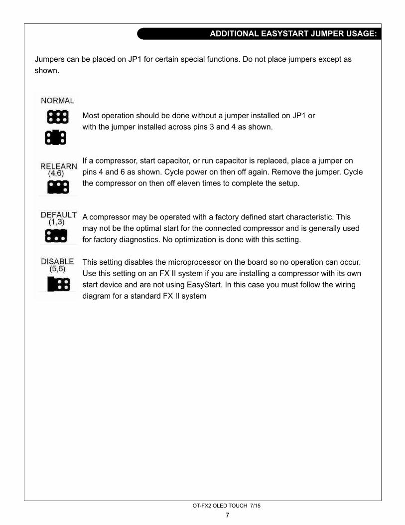
Jumpers can be placed on JP1 for certain special functions. Do not place jumpers except asshown.
Most operation should be done without a jumper installed on JP1 or with the jumper installed across pins 3 and 4 as shown.
If a compressor, start capacitor, or run capacitor is replaced, place a jumper on pins 4 and 6 as shown. Cycle power on then off again. Remove the jumper. Cycle the compressor on then off eleven times to complete the setup.
A compressor may be operated with a factory defined start characteristic. This may not be the optimal start for the connected compressor and is generally used for factory diagnostics. No optimization is done with this setting.
This setting disables the microprocessor on the board so no operation can occur. Use this setting on an FX II system if you are installing a compressor with its own start device and are not using EasyStart. In this case you must follow the wiring diagram for a standard FX II system

OT-FX2 OLED TOUCH 7/15
8
Sensor Connections: A loop water sensor must be connected to the OUTSIDE jack on the FXII power supply. No sensor should be connected to the ALT.AIR jack on the FXII power supply. A combination humidity and air sensor must be connected to the INTAKE and EXHAUST jacks on the FXII power supply.
This configuration requires a factory installed board, for connecting humiditysensors, on the FX II power supply. Output wiring does not follow the output labelswritten on the board. Follow the wiring diagram for the FAMU to wire this control.Relative humidity measurement is handled by two dual purpose sensors combininghumidity and temperature measurement that are placed at the intake and exhaust of the airhandler.The operating mode and fan symbol display is determined by the active outputs.
The temperature set point (SET) will alternate with two other values in the displayduring operation. Relative humidity (RH) of the exhaust and intake air temperature (OAT)will show at regular intervals. Relative humidity of the intake air may be viewed in thesystem status.
FRESH AIR MAKE UP UNIT (FAMU)
Heater active
Both heater and valve are active
Valve active
Fan active

OT-FX2 OLED TOUCH 7/15
9
FAMU SYSTEM OPERATION
The above graph illustrates the dehumidification process. The intake air temperature is reduced below the dew point. Moisture is removed from the air reducing the dew point and air temperature to point X. The air is then warmed by the electric heater to the set point.
The FAMU control will attempt to keep the exhaust air temperature within 2°F of set point and humidity below the humidity set point.

OT-FX2 OLED TOUCH 7/15
10
Line voltage, line frequency, system current, inlet humidity, and loop watertemperature can be viewed on the display. In the off mode or any operating mode, pressand hold either center touch area to view the status. To exit the status view, press andrelease any touch area on the display.
Fault Messages: Air Sensor Trouble (DX / AH) The temperature sensor in the display has failed. RH Inlet Sensor Trouble (FAMU) A problem exists with the intake humidity and air sensor. RH Outlet Sensor Trouble (FAMU) A problem exists with the exhaust humidity and air sensor. High Freon Pressure (DX) The High Freon pressure switch was opened. Low Freon Pressure (DX) The low Freon pressure switch was opened for 10 minutes Low AC Voltage (DX) Line voltage was below the limit set in the programmable parameters for greater than 10 minutes. System Over Current (DX) Sustained current draw existed that exceeded the programmed value. Check Water Pump (DX) Cooling water temperature is above the limit set in the programmable parameters. Lockout (DX) Four faults occurred within one hour. Press the On/Off icon twice (Off then on again) to clear the lockout.
VIEWING SYSTEM STATUS (FAMU VIEW MODE)

OT-FX2 OLED TOUCH 7/15
11
JUMPER SETTINGS
Hardware jumpers are provided on the FXII power supply to provide additional functions. See Programmable Parameters for additional configuration settings.
Display Selection: JP9 JP11 UsageOLED OFF OLED OLED display.FX-MAXX ON FXMAX FXMAX display.
Configuration:System JP7 JP8 UsageAH ON OFF ALLDX OFF ON With low Freon pressure switch.DX ON ON No low Freon pressure switch.FAMU ON OFF ALL

OT-FX2 OLED TOUCH 7/15
12
Descriptions of programmable parameters, factory default values, and allowable values are shown in the program parameters tables. Installed options and parameter selections control which parameters are displayed. Some parameters are not available with older revision displays. Separate tables are provided for DX, AH, and FAMU units following the parameter descriptions. FX II power supply jumpers must be properly configured prior to setting parameters.
Entering the program mode:To enter the program mode the display must be in the off mode. Press and hold the On / Off symbol for 3 seconds. Press the right arrow to advance to the next parameter and press the left arrow to go back to the last parameter. Press the up or down arrows to change the parameters value. Exit the program mode when finished by pressing the X or wait 60 seconds for the display to exit.
Parameter description: Cycled fan: (DX, AH) When set for cycled, the fan will operate on demand. When set for continuous, the fan will always run unless you turn the system off. Reverse fan in heat: (DX) Fan speed will increase as the room temperature rises if this parameter is set for reverse. If set for normal, fan speed will decrease as room temperature rises. This parameter only works in heat mode and the fan must be set for automatic operation. System units: (ALL) Degrees Fahrenheit (°F) or degrees Celsius (°C) can be selected Display brightness: (ALL) Display brightness can be set from 4 to 15 to suit room lighting. Brightness will change as the number is changed. Screen saver brightness: (ALL) Number values from 0 to 8 can be set to suit room brightness and the unit will operated as described in the screen saver section. Setting the parameter to 0 will cause the display to show nothing when in screen saver. Temperature calibration: (ALL) This parameter allows the user to calibrate the room air temperature sensor. The room temperature will be displayed and can be adjusted +/-10 °F or +/-5°C Staging delay: (DX) This parameter provides control of timing for compressor starts. When a system is first powered, the staging delay prevents the compressor from starting for the length of time set. When a cooling or heating cycle is completed, the compressor cannot restart until the staging delay has expired.
PROGRAMMABLE PARAMETERS

OT-FX2 OLED TOUCH 7/15
13
Alt air enabled: (AH) When set for alt air enabled, the alt air jack can be used with an optional air sensor to over ride the display mounted air sensor. When set for outside air enabled, an optional sensor may be installed to monitor outside air temperature. This will appear as OAT on the display. Electric heat/ No electric heat (AH, DX) Set this parameter only if the system is equipped with an electric heater. Contactors must be used if the current exceeds the rated value. If the loop water sensor is not installed or fails, electric heat will not be available and the system will open the valve when necessary regardless of loop temperature. Electric heat will only be used if the loop water temperature is less than ambient + 15°F (ambient + 8.3°C) AH: The electric heater is connected to the compressor L1 and compressor L2 terminals. Heater current must not exceed 30 Amps. DX: The electric heater is connected to the valve L1 and compressor L2 terminals. Heater current must not exceed 10 Amps. Staging delay should be adjusted if necessary. Fail safe level: (DX) There are four fail safe levels the controller can be set to operate with: OFF, 1, 2, and 3. If LOCKOUT appears in the display, the unit must be turned off then on again by touching
the Off/On symbol in order to clear LOCKOUT condition. Low AC line detection: (DX) When set, if the AC line voltage remains below the set value, the system will follow the action set by the failsafe level. De-Ice time: (DX) When set, the system will perform the evaporator de-icing program. Pump sentry: (DX) An optional sensor plugged into the “Outside” jack can be used to monitor the condenser coil temperature. If the temperature exceeds the set value, the failure will be handled according to the fail safe level programmed. This failure will prompt the user to CHECK WATER PUMP. Outside air temperature is not available when the pump sentry is used.
PROGRAMMABLE PARAMETERS
Off Do not detect or display any faults except air sensor failure1 The controller will detect a fault but will not display the fault message Operation will stop until the fault is cleared.2 The controller will detect and display all fault messages. Operation will stop until the fault is cleared.3 The controller will detect and display all fault messages. Operation will stop until the fault is cleared. After 4 faults the controller will LOCKOUT and prevent further operation

OT-FX2 OLED TOUCH 7/15
14
Cycled pump: (DX) When set for “Cycled”, the pump will run on demand. When set for “Continuous”, the pump will run continuously when the system is in cool, heat or auto mode. Normal water valve operation: (AH, FAMU) This feature allows service personnel to force the water valve open to facilitate bleeding air from the system. Selecting override will force the water valve open for four hours. Touch the on/off symbol to cancel this operation Fan A speed 1-6: (DX, AH) These parameters are used to optimize fan performance and airflow. Fan A controls the triac driven fan output on the FXII power supply. It also controls the DC fan connected to the fan A terminals on the DC fan option board if installed. Speed 1 corresponds to the lowest speed setting available from the display. Speed 6 corresponds to the highest speed setting. Fan speed will change as the parameter is changed so that adjustments can be observed. Fan B, C, and D speed 1-6: (DX, AH) These options will only be visible if the DC fan option board is installed. Adjustments are made in the same manner as fan A. See DC fan option board for details. CANBUS (DX,AH) This option should be enabled in systems with a CANBUS capable power supply only. All other users must leave this option set for DISABLED. Enabling this option allows the user to set the CAN unit ID and group ID. Unit ID: (DX, AH) This number is assigned at installation for use with the CAN system. It should only be changed by qualified service technicians. Group ID: (DX, AH) This number is assigned at installation for use with the CAN system. It should only be changed by qualified service technicians. EasyStart Graph (DX) This option should be enabled on systems equipped with EasyStart only. All other users must leave this option set for NONE. When the parameter is set for “SHOW” the display will show a graph of the compressor start each time a start occurs. The same graph is available from the view mode by tapping the upper center or lower center of the display touch pad. If this parameter is set for hide, the graph is hidden on each start but is still available from the view mode. When set for “NONE”, the graph is not available for viewing. Configure System: (ALL) This option selects between Fresh Air Makeup Unit (FAMU), Direct Expansion (DX) or Air Handler (AH) operation. On later software revisions, selecting a change requires confirmation. A Y or an N appears next to the change arrows. Press the Y to confirm the change or N to cancel the change. The display will return to show “Configure System” with your selection. Changing the system configuration will reset all parameters to factory defaults.
PROGRAMMABLE PARAMETERS

OT-FX2 OLED TOUCH 7/15
15
Humidity set point: (FAMU) This parameter sets the percent of relative humidity threshold for the fresh air makeup unit as measured at the air intake. If the percent of relative humidity rises to the programmed level, the control will begin dehumidifying air and continue until the relative humidity drops to five percent below the set value. Current Limit (DX) This option sets the maximum continuous current. If the current rises above this level for one second the system will shut down and a system over current fault will be displayed. Reset parameters: (ALL) To reset parameters to factory defaults, select YES and then exit the program mode by pressing the X in the top left of the touch screen. The display will show EEPROM RESET then show the room temperature in the off mode. The FAMU parameter is not reset.
PROGRAMMABLE PARAMETERS

OT-FX2 OLED TOUCH 7/15
16
Description Default ValueCycled fan Continuous Cycled or ContinuousSystem units °F °F or °CDisplay brightness 15 4=Minimum 15=MaximumScreen saver brightness 4 0 to 8Temperature calibration 0 Ambient +/- 10°FAlternate air enabled Alternate air enabled Alternate air enabled or Outside air enabledElectric Heat No Electric Heat Electric Heat or No Electric HeatNormal valve operation Normal valve operation Normal valve operation or Valve overrideFan A speed 1 30 30 to 90Fan A speed 2 35 30 to 90Fan A speed 3 40 30 to 90Fan A speed 4 45 30 to 90Fan A speed 5 55 30 to 90Fan A speed 6 85 30 to 90Fan B speed 1 30 30 to 90Fan B speed 2 35 30 to 90Fan B speed 3 40 30 to 90Fan B speed 4 45 30 to 90Fan B speed 5 55 30 to 90Fan B speed 6 85 30 to 90Fan C speed 1 30 30 to 90Fan C speed 2 35 30 to 90Fan C speed 3 40 30 to 90Fan C speed 4 45 30 to 90Fan C speed 5 55 30 to 90Fan C speed 6 85 30 to 90Fan D speed 1 30 30 to 90Fan D speed 2 35 30 to 90Fan D speed 3 40 30 to 90Fan D speed 4 45 30 to 90Fan D speed 5 55 30 to 90Fan D speed 6 85 30 to 90CAN BUS Disabled Enabled or DisabledCAN ID 0 0 to 254Group ID 0 0 to 254Configure System AH AH, FAMUReset Parameters No No or Yes
Italic parameters are for systems with the DC Fan Option Board only.
AIR HANDLER (AH) PROGRAMMABLE PARAMETERS TABLE

OT-FX2 OLED TOUCH 7/15
17
Description Default ValueCycled fan Continuous Cycled or ContinuousReverse fan in heat Reverse Reverse or NormalSystem units °F °F or °CDisplay brightness 15 4=Minimum 15=MaximumScreen saver brightness 4 0 to 8Temperature calibration 0 Ambient +/- 10°FStaging delay 15 5-135 SecondsFailsafe Level Off Off, 1, 2, 3Low AC line detection Off Off 75 to 100 (115VAC units) 175 to 200 (220 VAC units)De-Ice time Off Off, 30 to 90 secondsPump sentry Off Off, 100°F to 150°FCycled pump Cycled Cycled or ContinuousElectric Heat No Electric Heat Electric Heat or No Electric HeatFan A speed 1 30 30 to 90Fan A speed 2 35 30 to 90Fan A speed 3 40 30 to 90Fan A speed 4 45 30 to 90Fan A speed 5 55 30 to 90Fan A speed 6 85 30 to 90Fan B speed 1 30 30 to 90Fan B speed 2 35 30 to 90Fan B speed 3 40 30 to 90Fan B speed 4 45 30 to 90Fan B speed 5 55 30 to 90Fan B speed 6 85 30 to 90Fan C speed 1 30 30 to 90Fan C speed 2 35 30 to 90Fan C speed 3 40 30 to 90Fan C speed 4 45 30 to 90Fan C speed 5 55 30 to 90Fan C speed 6 85 30 to 90Fan D speed 1 30 30 to 90Fan D speed 2 35 30 to 90Fan D speed 3 40 30 to 90Fan D speed 4 45 30 to 90Fan D speed 5 55 30 to 90Fan D speed 6 85 30 to 90CAN BUS Disabled Enabled or DisabledUnit ID 1 1 to 253Group ID 1 1 to 253Easy Start Graph NONE None, Show, HideConfigure System DX DX, FAMUCurrent Limit Off 1 to 35 AmpsReset Parameters No No or Yes
Italic parameters are for systems with the DC Fan Option Board only.
DIRECT EXPANSION (DX) PROGRAMMABLE PARAMETERS TABLE
OT-FX2 OLED TOUCH 7/15
18
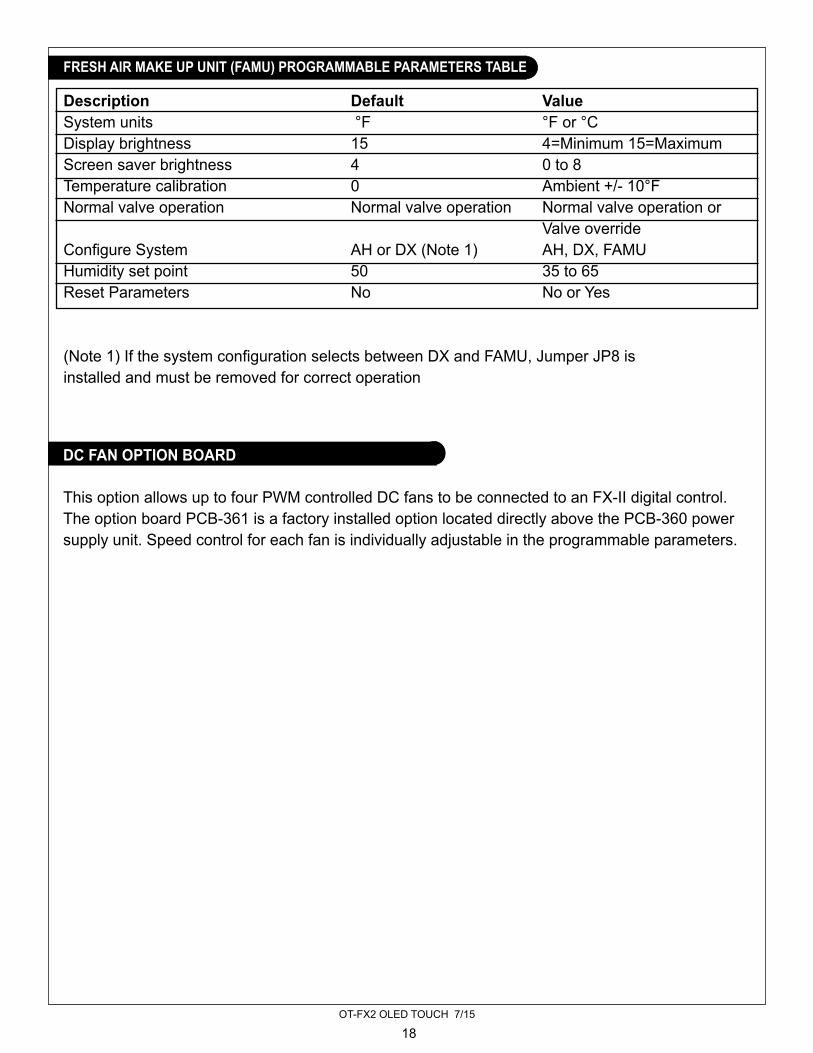
Description Default ValueSystem units °F °F or °CDisplay brightness 15 4=Minimum 15=MaximumScreen saver brightness 4 0 to 8Temperature calibration 0 Ambient +/- 10°FNormal valve operation Normal valve operation Normal valve operation or Valve overrideConfigure System AH or DX (Note 1) AH, DX, FAMUHumidity set point 50 35 to 65Reset Parameters No No or Yes
(Note 1) If the system configuration selects between DX and FAMU, Jumper JP8 isinstalled and must be removed for correct operation
FRESH AIR MAKE UP UNIT (FAMU) PROGRAMMABLE PARAMETERS TABLE
This option allows up to four PWM controlled DC fans to be connected to an FX-II digital control. The option board PCB-361 is a factory installed option located directly above the PCB-360 power supply unit. Speed control for each fan is individually adjustable in the programmable parameters.
DC FAN OPTION BOARD

OT-FX2 OLED TOUCH 7/15
19
Each fan is connected by three wires to the control board. Connect the control wires to their corresponding terminals on the option board. The 10V terminal is connected to the DC fans’ +10 volt output. The GND terminal is connected to the DC fans’ ground control wire only. Do not connect the GND wire to an AC ground. The FAN terminal is connected to the DC fans’ 0-10V signal wire.Connect the DC fan’s AC input directly to the AC line input. All other connections to the FXII power supply are as they would be in a normal installation.• The FXII power supply board provides an output for a triac driven fan connected to Fan L1
and Fan L2 on the power supply board. When connected, the fan will follow the speed control for Fan A on the DC fan option board.
• Do not connect the DC fan power source to the Fan L1 terminal on the power supply.
Connected fans will follow the six fan speeds selected on the display. If manual fan speed 4 is selected, all connected fans will be on speed 4.
It may be desirable in an installation to have one or more fans respond differently to the six fan speed control levels. The program parameter table B lists fans A, B, C and D each with six speed adjustment points. Fan A speed X controls both the triac driven fan output and the DC fan A output. Fans B, C, and D control only the DC fan output for the fan connected to that output. To make changes to fan A, first enter the program mode.(See the entering program mode section for details.) Advance through the parameters to the Fan A Speed 1 parameter. Fan A Speed 1 is the lowest fan speed setting for the triac driven fan and DC Fan A. Use the up and down pads to increase or decrease the fan speed to a desired level. Advance to speeds 2-6 and make changes to each speed as desired. Each fan speed parameter has an adjustment range of 30-90 with 90 being the fastest fan speed setting. Each speed parameter may be adjusted anywhere in this range. Adjustments may be made to fans B, C, and D in the same manner.
FAN CONNECTIONS:
INSTALLATION
OPERATION
ADJUSTING INDIVIDUAL FAN SPEEDS

OT-FX2 OLED TOUCH 7/15
20
General:Set point range 55°F to 85°F 12.7°C to 29.4°CAmbient temperature range displayed 5°F to 150°FTemperature sensor accuracy 2°F at 77°FLow voltage limit 115 VAC units 75VACLow voltage limit 230 VAC units 175VACLine voltage limit 250VACFrequency 50 or 60 HzMinimum operating temperature 0°FMaximum operating temperature 180°FMaximum RH conditions (Board and display) 95 % Non-condensingMaximum length of the display cable 75 FeetMaximum length of the Outside air sensor cable 50 FeetApplication:Direct Expansion (DX):Fan output MAX 6 AmpsValve output MAX(Or electric heater connected to valve output) 10 Amps MaximumPump output MAX ¼ HP at 115 VAC ½ HP at 230 VACCompressor output 1HP at 115 VAC 2HP at 230 VACAir Handler (AH):Electric heater output(Connected to compressor L1 and L2) 30 Amps MaximumValve output MAX 10 Amps MaximumFan output MAX 6 AmpsFresh Air Make Up Unit(FAMU)RH measurement range 5% to 100%Electric heater output(Connected to Fan L1 and L2) 20 Amps MaximumValve output MAX 10 Amps MaximumFan output MAX(Connected to Pump L1 and L2) 10 Amps Maximum
SPECIFICATIONS

OT-FX2 OLED TOUCH 7/15
21
AH WIRING DIAGRAM

OT-FX2 OLED TOUCH 7/15
22
DX WIRING DIAGRAM

OT-FX2 OLED TOUCH 7/15
23
FXII FRESH AIR MAKE UP UNIT WIRING

OT-FX2 OLED TOUCH 7/15
24
DX WIRING DIAGRAM

1419 W. Newport Center Drive, Deerfield Beach, FL 33442Tel: (954) 421-1717 • www.northern-lights.comNorthern Lights and Technicold are registered trademarks of Northern Lights, Inc. © 2015 All rights reserved. Litho USA. OTFX2