operator’s manual owner's manual -...
TRANSCRIPT

English 580 95 96-27
Operator’s Manual Owner's Manual
LGT2654
Gasoline containing up to 10% ethanol (E10) is accept-able for use in this machine. The use of any gasoline ex-ceeding 10% ethanol (E10) will void the product warranty.
Esta máquina puede utilizar gasolina con un contenido de hasta el 10% de etanol (E10). El uso de una gasolina que supere el 10% de etanol (E10) anulará la garantía del producto. the product warranty.
Please read the operator's manual carefully and make sure you understand the instructions before using the machine.
Por favor lea cuidadosamente y comprenda estas intrucciones antes de usar esta maquina.

2
SAFETY RULESSafe Operation Practices for Ride-On Mowers
DANGER: THIS CUTTING MACHINE IS CAPABLE OF AMPUTATING HANDS AND FEET AND THROW ING OBJECTS. FAILURE TO OBSERVE THE FOLLOWING SAFETY INSTRUCTIONS COULD RESULT IN SERIOUS INJURY OR DEATH.
• Never leave a running machine unattended. Always turn off blades, set parking brake, stop engine, and remove keys before dismounting.
• Disengage blades when not mowing. Shut off engine and wait for all parts to come to a complete stop before cleaning the machine, removing the grass catcher, or unclogging the discharge chute.
• Operate machine only in daylight or good artificial light.• Do not operate the machine while under the influence of
alcohol or drugs.• Watch for traffic when operating near or crossing road ways.• Use extra care when loading or unloading the machine
into a trailer or truck.• Always wear eye protection when operating machine.• Data indicates that operators, age 60 years and above,
are involved in a large percentage of riding mower-related injuries. These operators should evaluate their ability to operate the riding mower safely enough to protect them- selves and others from serious injury.
• Follow the manufacturer's recommendation for wheel weights or counterweights.
• Keep machine free of grass, leaves or other debris build-up which can touch hot exhaust / engine parts and burn. Do not allow the mower deck to plow leaves or other debris which can cause build-up to occur. Clean any oil or fuel spillage before operating or storing the machine. Allow machine to cool before storage.
II. SLOPE OPERATIONSlopes are a major factor related to loss of control and tip-over accidents, which can result in severe injury or death. Operation on all slopes requires extra caution. If you cannot back up the slope or if you feel uneasy on it, do not mow it.• Mow up and down slopes, not across.• Watch for holes, ruts, bumps, rocks, or other hidden ob-
jects. Uneven terrain could overturn the machine. Tall grass can hide obstacles.
• Choose a low ground speed so that you will not have to stop or shift while on the slope.
• Do not mow on wet grass. Tires may lose traction. Always keep the machine in gear when going down slopes.
Do not shift to neutral and coast downhill.• Avoid starting, stopping, or turning on a slope. If the tires
lose traction, disengage the blades and proceed slowly straight down the slope.
• Keep all movement on the slopes slow and gradual. Do not make sudden changes in speed or direction, which could cause the machine to roll over.
• Use extra care while operating machine with grass catch-ers or other at tach ments; they can affect the stability of the machine. Do no use on steep slopes.
• Do not try to stabilize the machine by putting your foot on the ground.
• Do not mow near drop-offs, ditches, or embankments. The machine could suddenly roll over if a wheel is over the edge or if the edge caves in.
I. GENERAL OPERATION • Read, understand, and follow all instructions on the ma-
chine and in the manual before starting.• Do not put hands or feet near rotating parts or under the
machine. Keep clear of the discharge opening at all times.• Only allow responsible adults, who are familiar with the
in struc tions, to operate the machine.• Clear the area of objects such as rocks, toys, wire, etc.,
which could be picked up and thrown by the blades.• Ensure the area is clear of bystanders before operating.
Stop machine if anyone enters the area.• Never carry passengers.• Do not mow in reverse unless absolutely necessary.
Always look down and behind before and while back ing.• Never direct discharged material toward anyone. Avoid
discharging material against a wall or obstruction. Material may ricochet back toward the operator. Stop the blades when crossing gravel surfaces.
• Do not operate machine without the entire grass catcher, discharge chute, or other safety devices in place and working.
• Slow down before turning.
WARNING: In order to prevent ac ci den tal starting when setting up, trans port ing, ad just ing or making repairs, al ways dis con- nect spark plug wire and place wire where it can not contact spark plug.
WARNINGEngine exhaust, some of its con stit u ents, and cer tain vehicle com po nents contain or emit chem i cals known to the State of Cal i for nia to cause can cer and birth de fects or oth er re pro duc tive harm.
WARNINGBattery posts, terminals and related ac ces so ries contain lead and lead compounds, chem i cals known to the State of Cal i for nia to cause can cer and birth defects or oth er re pro duc tive harm. Wash hands after handling.
WARNING: Do not coast down a hill in neut-ral, you may lose control of the tractor.
WARNING: Tow only the attachments that are rec om mend ed by and comply with spec i fi ca tions of the man u fac tur er of your tractor. Use common sense when towing. Operate only at the low est possible speed when on a slope. Too heavy of a load, while on a slope, is dan ger ous. Tires can lose trac tion with the ground and cause you to lose control of your tractor.
3
SAFETY RULESSafe Operation Practices for Ride-On Mowers
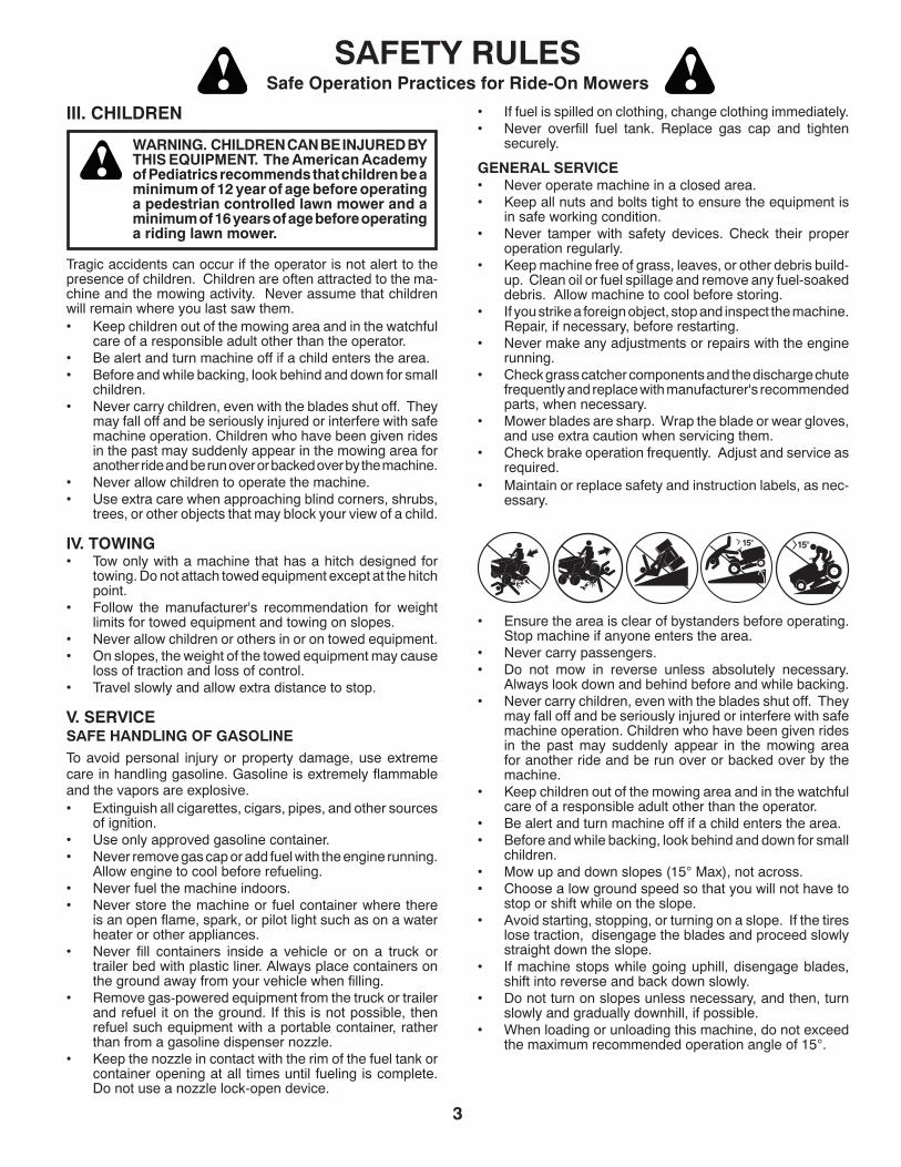
• Ensure the area is clear of bystanders before operating. Stop machine if anyone enters the area.
• Never carry passengers.• Do not mow in reverse unless absolutely necessary.
Al ways look down and behind before and while backing.• Never carry children, even with the blades shut off. They
may fall off and be seriously injured or interfere with safe machine operation. Children who have been given rides in the past may suddenly appear in the mowing area for another ride and be run over or backed over by the machine.
• Keep children out of the mowing area and in the watchful care of a responsible adult other than the operator.
• Be alert and turn machine off if a child enters the area.• Before and while backing, look behind and down for small
children.• Mow up and down slopes (15° Max), not across.• Choose a low ground speed so that you will not have to
stop or shift while on the slope.• Avoid starting, stopping, or turning on a slope. If the tires
lose traction, disengage the blades and proceed slowly straight down the slope.
• If machine stops while going uphill, disengage blades, shift into reverse and back down slowly.
• Do not turn on slopes unless necessary, and then, turn slowly and gradually downhill, if possible.
• When loading or unloading this machine, do not exceed the maximum recommended operation angle of 15°.
III. CHILDREN
WARNING. CHILDREN CAN BE INJURED BY THIS EQUIPMENT. The American Academy of Pediatrics recommends that children be a minimum of 12 year of age before operating a pedestrian controlled lawn mower and a minimum of 16 years of age before operating a riding lawn mower.
Tragic accidents can occur if the operator is not alert to the presence of children. Children are often attracted to the ma-chine and the mowing activity. Never assume that children will remain where you last saw them.• Keep children out of the mowing area and in the watchful
care of a responsible adult other than the operator.• Be alert and turn machine off if a child enters the area.• Before and while backing, look behind and down for small
children. • Never carry children, even with the blades shut off. They
may fall off and be seriously injured or interfere with safe machine operation. Children who have been given rides in the past may suddenly appear in the mowing area for another ride and be run over or backed over by the machine.
• Never allow children to operate the machine.• Use extra care when approaching blind corners, shrubs,
trees, or other objects that may block your view of a child.
IV. TOWING• Tow only with a machine that has a hitch designed for
towing. Do not attach towed equipment except at the hitch point.
• Follow the manufacturer's recommendation for weight limits for towed equipment and towing on slopes.
• Never allow children or others in or on towed equipment.• On slopes, the weight of the towed equipment may cause
loss of traction and loss of control.• Travel slowly and allow extra distance to stop.
V. SERVICESAFE HANDLING OF GASOLINETo avoid personal injury or property damage, use extreme care in handling gasoline. Gasoline is extremely flammable and the vapors are explosive.• Extinguish all cigarettes, cigars, pipes, and other sources
of ignition.• Use only approved gasoline container.• Never remove gas cap or add fuel with the engine running.
Allow engine to cool before refueling.• Never fuel the machine indoors.• Never store the machine or fuel container where there
is an open flame, spark, or pilot light such as on a water heater or other appliances.
• Never fill containers inside a vehicle or on a truck or trailer bed with plastic liner. Always place containers on the ground away from your vehicle when filling.
• Remove gas-powered equipment from the truck or trailer and refuel it on the ground. If this is not possible, then refuel such equipment with a portable container, rather than from a gasoline dispenser nozzle.
• Keep the nozzle in contact with the rim of the fuel tank or container opening at all times until fueling is complete. Do not use a nozzle lock-open device.
• If fuel is spilled on clothing, change clothing immediately.• Never overfill fuel tank. Replace gas cap and tighten
securely.
GENERAL SERVICE• Never operate machine in a closed area.• Keep all nuts and bolts tight to ensure the equipment is
in safe working condition.• Never tamper with safety devices. Check their proper
operation regularly.• Keep machine free of grass, leaves, or other debris build-
up. Clean oil or fuel spillage and remove any fuel-soaked debris. Allow machine to cool before storing.
• If you strike a foreign object, stop and inspect the machine. Repair, if necessary, before restarting.
• Never make any adjustments or repairs with the engine run ning.
• Check grass catcher components and the discharge chute frequently and replace with manufacturer's recommended parts, when necessary.
• Mower blades are sharp. Wrap the blade or wear gloves, and use extra caution when servicing them.
• Check brake operation frequently. Adjust and service as required.
• Maintain or replace safety and instruction labels, as nec-essary.

4
SAFETY RULES ......................................................... 2-3PRODUCT SPECIFICATIONS ....................................... 4CUSTOMER RESPONSIBILITIES ................................. 4ASSEMBLY ................................................................. 6-9OPERATION ........................................................... 10-16MAINTENANCE SCHEDULE ...................................... 17
MAINTENANCE ..................................................... 17-21SERVICE AND AD JUST MENTS ............................ 22-26STORAGE .................................................................... 27TROU BLE SHOOT ING ............................................ 28-29WARRANTY ............................................................ 31-34ESPAÑOL .................................................................... 35
TABLE OF CONTENTS
PRODUCT SPECIFICATIONSGasoline Capacity 4 Gallons/15,14 L and type: Unleaded Regular
Oil Type (API: SG-SL): SAE 30 (above 32°F/0°C) SAE 5W30 (below 32°F/0°C)
Oil Capacity: W/Filter 64 oz/1,96 L W/out Filter 60 oz/1,77 L
Spark Plug: Champion QC12YC (Gap: .040"/1.02 mm)
Ground Speed (MPH/KPH): Forward: 0 - 5.2/8,4 Reverse: 0 - 2.9/4,7
Charging System: 15 AMPS @ 3600 RPM
Battery: AMP/HR: 28 MIN. CCA: 230 Case Size: U1R
Blade Bolt Torque: 45-55 FT. LBS./62-75 Nm
CONGRATULATIONS on your purchase of a new tractor. It has been designed, engineered and manu fac tured to give you the best possible dependability and performance.Should you experience any problem you cannot easily remedy, please contact your nearest authorized service center/department. We have com pe tent, well-trained tech ni- cians and the proper tools to service or repair this tractor.Please read and retain this manual. The instructions will enable you to assemble and maintain your tractor prop erly. Always observe the “SAFETY RULES”.
REPAIR AGREEMENTA Repair Agreement is available on this prod uct. Contact your nearest Sears store for details.
CUSTOMER RESPONSIBILITIES• Read and observe the safety rules.• Follow a regular schedule in maintaining, caring for
and using your tractor.• Follow the instructions in the Maintenance and Storage
sections of this manual. • Wear proper Personal Protective Equipment (PPE)
while operating this machine, including (at a minimum) sturdy footwear, eye protection, and hearing protection. Do not mow in shorts and/or open toed footwear.
• Always let someone know you are outside mowing.
WARNING: This tractor is equipped with an internal com- bus tion engine and should not be used on or near any un- im proved forest-covered, brush-covered or grass-cov ered land unless the engine’s exhaust system is equipped with a spark arrester meeting applicable local or state laws (if any). If a spark arrester is used, it should be maintained in effective working order by the operator.In the state of California the above is required by law (Sec-tion 4442 of the California Public Resources Code). Other states may have similar laws. Federal laws apply on federal lands. A spark arrester for the muffler is available through your nearest authorized service center/department .
5
UNASSEMBLED PARTS
(5) Large Retainer Springs
(1) Small Retainer Springs
61/3-1 )5( srehsaW .D.O
(2) Rear Lift LinkAssemblies
(1) Front Lift Link Assembly
(1) Anti-Sway Bar (1) 3/4 O.D. Washers
(1) Small Retainer Springs
(1) 1-1/4 O.D. Washer
(1) Wheel (1) 3/8-16 Locknut
(1) Shoulder Bolt
Mower
If Equipped
(2) Keys
Slope Sheet
Keys
(1) Oil Drain Tube
Mower Front Wheel
*Installed by Dealer
Battery
(1) Quick Connect
(2) Hex Bolts
(2) Nut Keps *Brush Guard Kit

6
NOTE: You may now roll your tractor off the skid. Follow the instructions below to remove the tractor from the skid.
WARNING: Before start ing, read, un der stand and fol low all in struc tions in the Op er a tion section of this man u al. Be sure tractor is in a well-ventilated area. Be sure the area in front of tractor is clear of other peo ple and objects.
TO ROLL TRACTOR OFF SKID (See Op er a tion section for location and function of con trols)• Raise attachment lift lever to its highest po si tion.• Release parking brake by de press ing clutch/brake ped al.• Place freewheel control in "trans mis sion dis en gaged"
position (See “TO TRANS PORT” in the Op er a tion section of this manual).
• Roll tractor forward off skid.Continue with the instructions that follow.
Fig. 2
ASSEMBLY
ADJUST SEAT (See Fig. 2)• Sit in seat.• Lift up adjustment lever (A) and slide seat until a com-
fortable position is reached which allows you to press clutch/brake pedal all the way down.
• Release lever to lock seat in position.
TO INSTALL MOWER AND DRIVE BELT (See Figs. 3 - 14)1. SET PARKING BRAKE LEVER AND LOWER AT-
TACHMENT LIFT (See Fig. 3)• Depress clutch/brake pedal all the way down and hold.• Pull parking brake lever up and hold, re lease pres sure
from clutch/brake pedal, then release parking brake lever. Pedal should re main in brake position. Ensure parking brake will hold tractor secure.
PARKING BRAKE LEVER
Fig. 3
• The attachment lift switch is used to raise and lower the mower deck or other attachments mounted to your tractor. Ignition must be on to operate this switch.
• Lower attachment lift to its lowest position.
Fig. 1
LABEL
TO CHECK BATTERY (See Fig. 1)• Lift hood to raised position.
NOTE: If this battery is put into service after month and year indicated on label (label is located between terminals) charge battery for minimum of one hour at 6-10 amps. (See "BATTERY" in Maintenance section of this manual for charging instructions).
• For battery and battery cable installation see "RE-PLACING BATTERY" in the "Service and Adjustments" section in this manual.
TO REMOVE TRACTOR FROM CARTONUNPACK CARTON• Remove all accessible loose parts and parts cartons
from carton .• Cut along dotted lines on all four panels of carton.
Remove end panels and lay side panels flat.• Remove mower and packing materials.• Check for any additional loose parts or cartons and
remove.
BEFORE REMOVING TRACTOR FROM SKID
Your new tractor has been assembled at the factory with exception of those parts left unassembled for shipping purposes. To ensure safe and proper operation of your tractor all parts and hardware you assemble must be tightened securely. Use the correct tools as necessary to ensure proper tightness.
TOOLS REQUIRED FOR ASSEMBLYA socket wrench set will make assembly easier. Stan dard wrench sizes are listed.
(2) 7/16" wrenches Utility knife
(1) 1/2" wrench Tire pressure gauge
(1) 3/4" wrench Pliers
(1) 3/4" socket w/drive ratchet
(1) 9/16" wrench FlashlightWhen right or left hand is mentioned in this man ual, it means when you are in the operating po si tion (seated be hind the steer ing wheel).
A
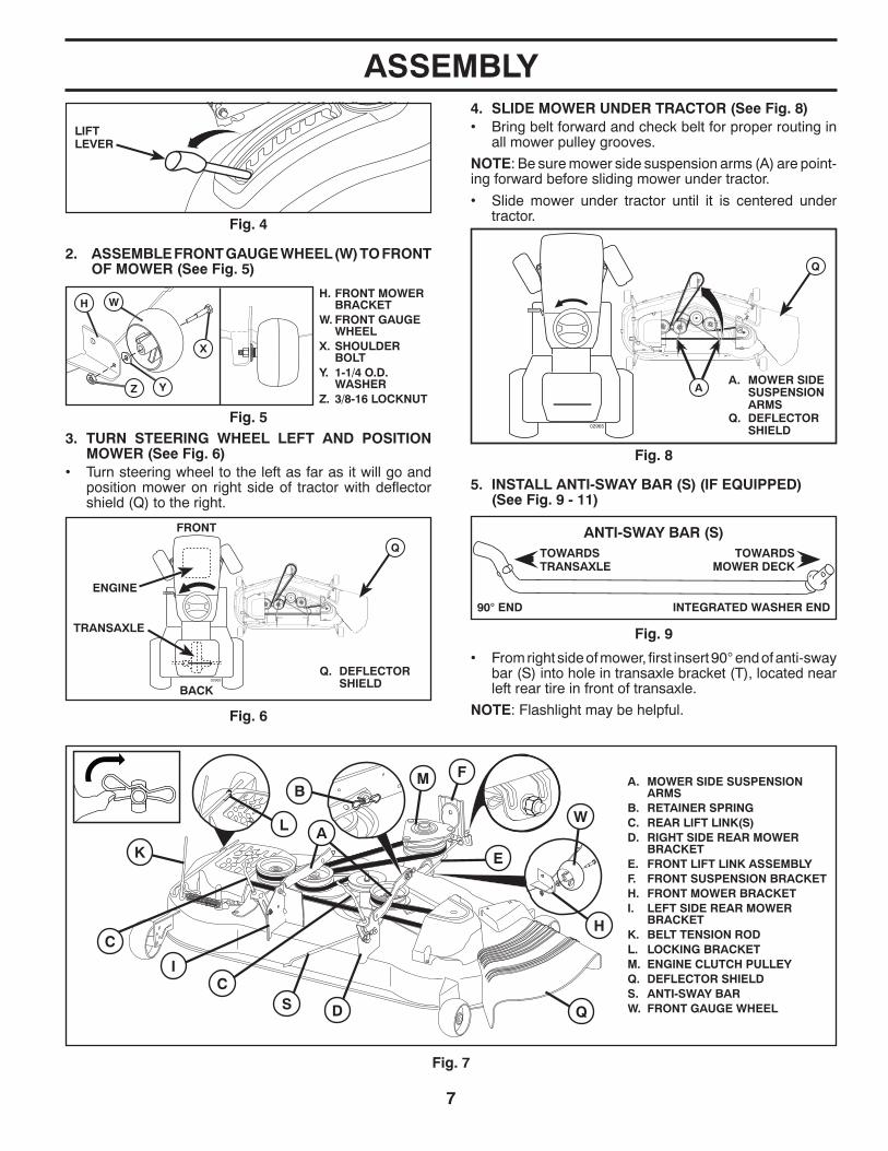
7
ASSEMBLY
A. MOWER SIDE SUSPENSION ARMS
B. RETAINER SPRINGC. REAR LIFT LINK(S)D. RIGHT SIDE REAR MOWER
BRACKETE. FRONT LIFT LINK ASSEMBLYF. FRONT SUSPENSION BRACKETH. FRONT MOWER BRACKETI. LEFT SIDE REAR MOWER
BRACKETK. BELT TENSION RODL. LOCKING BRACKETM. ENGINE CLUTCH PULLEYQ. DEFLECTOR SHIELDS. ANTI-SWAY BARW. FRONT GAUGE WHEEL
E
A
M FB
K
C
C
S
W
H
Q
I
D
L
TRANSAXLE
02965
FRONT
BACK
ENGINE
Q. DEFLECTOR SHIELD
Q
Fig. 6
90° END INTEGRATED WASHER END
ANTI-SWAY BAR (S)TOWARDS TOWARDS TRANSAXLE MOWER DECK
• From right side of mower, first insert 90° end of anti-sway bar (S) into hole in transaxle bracket (T), located near left rear tire in front of transaxle.
NOTE: Flashlight may be helpful.
5. INSTALL ANTI-SWAY BAR (S) (IF EQUIPPED) (See Fig. 9 - 11)
Fig. 9
02965
A. MOWER SIDE SUSPENSION ARMS
Q. DEFLECTOR SHIELD
Q
A
Fig. 8
4. SLIDE MOWER UNDER TRACTOR (See Fig. 8)• Bring belt forward and check belt for proper routing in
all mower pulley grooves.
NOTE: Be sure mower side suspension arms (A) are point-ing forward before sliding mower under tractor.
• Slide mower under tractor until it is centered under tractor.
LIFT LEVER
Fig. 4
H. FRONT MOWER BRACKET
W. FRONT GAUGE WHEEL
X. SHOULDER BOLT
Y. 1-1/4 O.D. WASHER
Z. 3/8-16 LOCKNUT
Fig. 5
YZ
WH
X
Fig. 7
3. TURN STEERING WHEEL LEFT AND POSITION MOWER (See Fig. 6)
• Turn steering wheel to the left as far as it will go and position mower on right side of tractor with deflector shield (Q) to the right.
2. ASSEMBLE FRONT GAUGE WHEEL (W) TO FRONT OF MOWER (See Fig. 5)
8
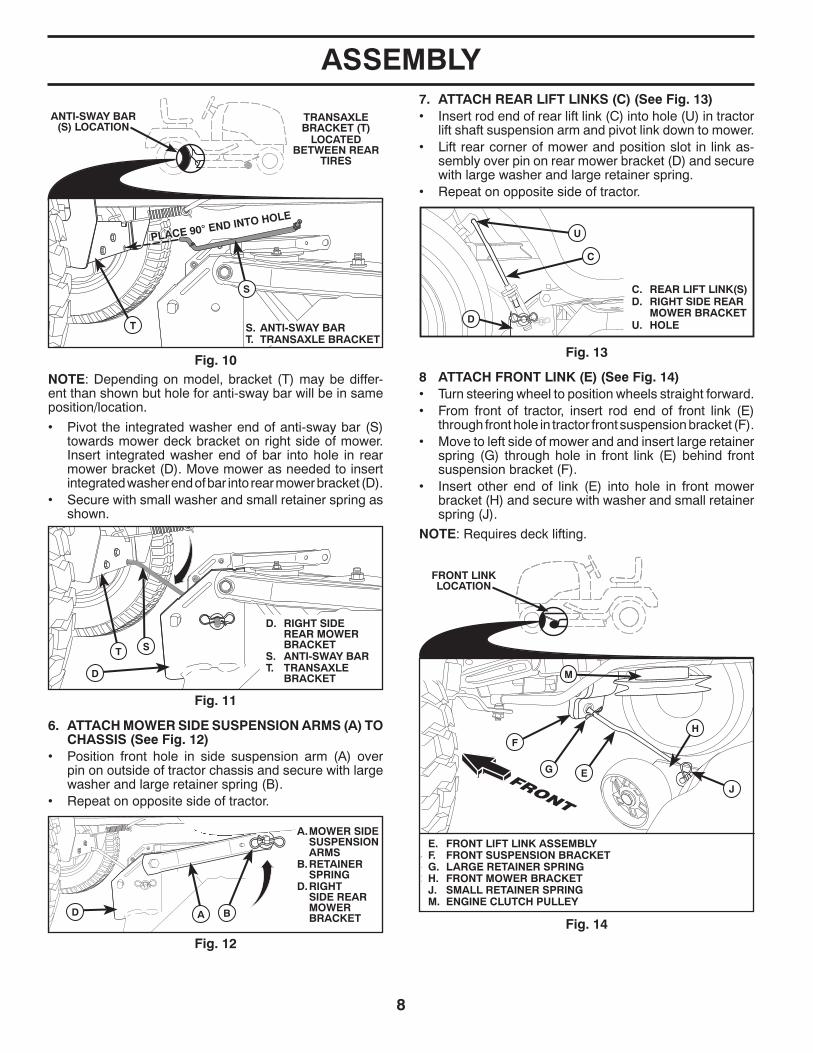
ASSEMBLY
6. ATTACH MOWER SIDE SUSPENSION ARMS (A) TO CHASSIS (See Fig. 12)
• Position front hole in side suspension arm (A) over pin on outside of tractor chassis and secure with large washer and large retainer spring (B).
• Repeat on opposite side of tractor.
BD A
A. MOWER SIDE SUSPENSION ARMS
B. RETAINER SPRING
D. RIGHT SIDE REAR MOWER BRACKET
Fig. 12
NOTE: Depending on model, bracket (T) may be differ-ent than shown but hole for anti-sway bar will be in same position/location.
ANTI-SWAY BAR (S) LOCATION
TRANSAXLE BRACKET (T)
LOCATED BETWEEN REAR
TIRES
PLACE 90° END INTO HOLE
PLACE 90° END INTO HOLE
S
T S. ANTI-SWAY BART. TRANSAXLE BRACKET
Fig. 108 ATTACH FRONT LINK (E) (See Fig. 14)• Turn steering wheel to position wheels straight forward.• From front of tractor, insert rod end of front link (E)
through front hole in tractor front suspension bracket (F).• Move to left side of mower and and insert large retainer
spring (G) through hole in front link (E) behind front suspension bracket (F).
• Insert other end of link (E) into hole in front mower bracket (H) and secure with washer and small retainer spring (J).
NOTE: Requires deck lifting.
Fig. 14
FRONT LINK LOCATION
EG
F
M
E. FRONT LIFT LINK ASSEMBLYF. FRONT SUSPENSION BRACKETG. LARGE RETAINER SPRINGH. FRONT MOWER BRACKETJ. SMALL RETAINER SPRINGM. ENGINE CLUTCH PULLEY
J
H
Fig. 13
7. ATTACH REAR LIFT LINKS (C) (See Fig. 13)• Insert rod end of rear lift link (C) into hole (U) in tractor
lift shaft suspension arm and pivot link down to mower.• Lift rear corner of mower and position slot in link as-
sembly over pin on rear mower bracket (D) and secure with large washer and large retainer spring.
• Repeat on opposite side of tractor.
C. REAR LIFT LINK(S)D. RIGHT SIDE REAR
MOWER BRACKETU. HOLED
C
U
S
D
T
D. RIGHT SIDE REAR MOWER BRACKET
S. ANTI-SWAY BART. TRANSAXLE
BRACKET
Fig. 11
• Pivot the integrated washer end of anti-sway bar (S) towards mower deck bracket on right side of mower. Insert integrated washer end of bar into hole in rear mower bracket (D). Move mower as needed to insert integrated washer end of bar into rear mower bracket (D).
• Secure with small washer and small retainer spring as shown.
9
ASSEMBLY
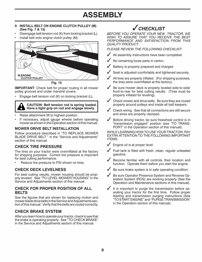
CHECK TIRE PRESSUREThe tires on your tractor were overinflated at the factory for shipping purposes. Correct tire pressure is important for best cutting performance.• Reduce tire pressure to PSI shown on tires.
CHECK DECK LEVELNESSFor best cutting results, mower housing should be prop-erly leveled. See “TO LEVEL MOWER HOUSING” in the Service and Adjustments section of this manual.
CHECK FOR PROPER POSITION OF ALL BELTSSee the figures that are shown for replacing motion and mower blade drive belts in the Service and Adjustments sec- tion of this manual. Verify that the belts are routed cor rect ly.
CHECK BRAKE SYSTEMAfter you learn how to operate your tractor, check to see that the brake is operating properly. See “TO CHECK BRAKE” in the Service and Adjustments section of this manual.
✓CHECKLISTBEFORE YOU OPERATE YOUR NEW TRAC TOR, WE WISH TO ASSURE THAT YOU RECEIVE THE BEST PERFORMANCE AND SATISFACTION FROM THIS QUALITY PRODUCT.
PLEASE REVIEW THE FOLLOWING CHECKLIST:
✓ All assembly instructions have been com plet ed.
✓ No remaining loose parts in carton.
✓ Battery is properly prepared and charged.
✓ Seat is adjusted comfortably and tightened securely.
✓ All tires are properly inflated. (For shipping purposes, the tires were overinflated at the factory).
✓ Be sure mower deck is properly leveled side-to-side/front-to-rear for best cutting results. (Tires must be properly inflated for leveling).
✓ Check mower and drive belts. Be sure they are routed properly around pulleys and inside all belt keepers.
✓ Check wiring. See that all connections are still secure and wires are properly clamped.
✓ Before driving tractor, be sure free wheel control is in “transmission engaged” position (see “TO TRANS- PORT” in the Operation section of this man u al).
WHILE LEARNING HOW TO USE YOUR TRACTOR, PAY EXTRA ATTENTION TO THE FOLLOWING IMPORTANT ITEMS:
✓ Engine oil is at proper level.
✓ Fuel tank is filled with fresh, clean, regular unleaded gasoline.
✓ Become familiar with all controls, their location and function. Operate them before you start the engine.
✓ Be sure brake system is in safe operating condition.
✓ Be sure Operator Presence System and Reverse Op-eration System (ROS) are working properly (See the Operation and Maintenance sections in this manual).
✓ It is important to purge the transmission before op- er at ing your tractor for the first time. Follow proper starting and transmission purging instructions (See “TO START EN GINE” and “PURGE TRANSMISSION” in the Op er a tion section of this manual).
9 INSTALL BELT ON ENGINE CLUTCH PULLEY (M) (See Fig. 7 & 15)
• Disengage belt tension rod (K) from locking bracket (L).• Install belt onto engine clutch pulley (M).
M. ENGINE CLUTCH PULLEY
M
Fig. 15
IMPORTANT: Check belt for proper routing in all mower pulley grooves and under mandrel covers.
• Engage belt tension rod (K) on locking bracket (L).
CAUTION: Belt tension rod is spring loaded. Have a tight grip on rod and engage slowly.
• Raise attachment lift to highest position.• If necessary, adjust gauge wheels before op er at ing
mower as shown in the Operation section of this manual.
MOWER DRIVE BELT INSTALLATION Follow procedure described in “TO REPLACE MOWER BLADE DRIVE BELT ” in the "Service and Adjustments" section of this manual.
10
These symbols may appear on your tractor or in literature supplied with the product. Learn and understand their meaning.
DANGER, KEEP HANDSAND FEET AWAY
FREE WHEEL(Automatic Models only)
KEEP AREA CLEAR SLOPE HAZARDS
15 15
(SEE SAFETY RULES SECTION)
BATTERY REVERSE FORWARD
FAST SLOW
ENGINE ONENGINE OFF
FUEL
CHOKE
MOWER HEIGHT
REVERSE NEUTRAL HIGH LOW
ATTACHMENTCLUTCH ENGAGED
PARKING BRAKE
IGNITION SWITCH
ATTACHMENTCLUTCH DISENGAGED
ENGINE START MOWER LIFT
Failure to follow instructionscould result in serious injury ordeath. The safety alert symbolis used to identify safety inform-ation about hazards which canresult in death, serious injuryand/or property damage.
DANGER indicates a hazard which, if not avoided,will result in death or serious injury.
WARNING indicates a hazard which, if not avoided,could result in death or serious injury.
CAUTION indicates a hazard which, if not avoided,might result in minor or moderate injury.
CAUTION when used without the alert symbol,indicates a situation that could result in damageto the tractor and/or engine.
FIRE indicates a hazard which, if not avoided,could result in death, serious injury and/orproperty damage.
HOT SURFACES indicates a hazard which,if not avoided, could result in death, serious injuryand/or property damage.
REVERSEOPERATION
SYSTEM (ROS)
LIGHTS ON CLUTCH/BRAKEPEDAL
CRUISE CONTROL
OPERATION

11
KNOW YOUR TRACTOR
READ THIS OPERATOR'S MANUAL AND SAFETY RULES BEFORE OPERATING YOUR TRACTORCompare the illustrations with your tractor to familiarize yourself with the locations of various controls and ad just ments. Save this manual for future reference.
Our tractors conform to the applicable safety standards of the American National Standards Institute.
Fig. 16
(A) ATTACHMENT LIFT LEVER - Used to raise and lower the mower or other attachments mounted to your trac tor.
(B) BRAKE PEDAL - Used for brak ing the tractor and start ing the engine.
(C) PARKING BRAKE - Locks clutch/brake pedal into the brake position.
(D) THROTTLE/CHOKE CONTROL - Used for starting and controlling engine speed.
(E) ATTACHMENT CLUTCH SWITCH - Used to engage the mow er blades, or other at tach ments mounted to your tractor.
(F) IGNITION SWITCH - Used for starting and stopping the engine.
(G) REVERSE OPERATION SYSTEM (ROS) "ON" PO-SITION - Allows operation of mower or other powered attachment while in reverse.
(H) LIGHT SWITCH - Turns the headlights on and off.
(J) MOTION CONTROL LEVER - Selects the speed and di rec tion of the tractor.
(M) FREEWHEEL CONTROL - Disengages transmission for pushing or slowly tow ing the trac tor with the engine off.
(P) SERVICE REMINDER/HOUR METER - Indicates when service is required for the engine and mower.
(Q) 12-VOLT POWER PORT - Used for 12-volt accessories.
A
D
B
C
H
E
M
J
P
Q
F
G
OPERATION
12
Fig. 17
The operation of any tractor can result in foreign objects thrown into the eyes, which can result in severe eye dam age. Always wear safety glass es or eye shields while operating your tractor or per form ing any ad just ments or repairs. We rec om mend standard safety glasses or a wide vision safety mask worn over spectacles.
Fig. 19
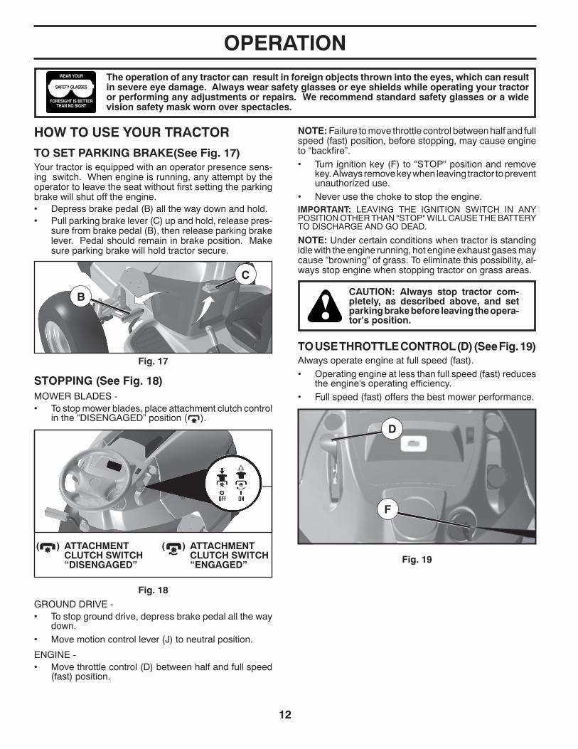
HOW TO USE YOUR TRAC TOR
TO SET PARKING BRAKE(See Fig. 17)Your tractor is equipped with an operator presence sens- ing switch. When engine is running, any attempt by the op er a tor to leave the seat without first setting the parking brake will shut off the engine.• Depress brake pedal (B) all the way down and hold.• Pull parking brake lever (C) up and hold, re lease pres-
sure from brake pedal (B), then release parking brake lever. Pedal should re main in brake position. Make sure parking brake will hold tractor secure.
Fig. 18
B
C
D
F
( ) ATTACHMENT CLUTCH SWITCH “ENGAGED”
( ) ATTACHMENT CLUTCH SWITCH “DIS EN GAGED”
GROUND DRIVE -• To stop ground drive, depress brake pedal all the way
down.• Move motion control lever (J) to neutral position.
ENGINE - • Move throttle control (D) between half and full speed
(fast) position.
STOPPING (See Fig. 18)MOWER BLADES -• To stop mower blades, place attachment clutch control
in the “DIS EN GAGED” position ( ).
NOTE: Failure to move throttle control between half and full speed (fast) position, before stopping, may cause engine to “backfire”.• Turn ignition key (F) to “STOP” position and remove
key. Always remove key when leaving tractor to prevent un au tho rized use.
• Never use the choke to stop the engine.IMPORTANT: LEAVING THE IGNITION SWITCH IN ANY POSITION OTHER THAN "STOP" WILL CAUSE THE BATTERY TO DISCHARGE AND GO DEAD.
NOTE: Under certain conditions when tractor is standing idle with the engine running, hot engine exhaust gases may cause “browning” of grass. To eliminate this possibility, al-ways stop engine when stopping tractor on grass areas.
CAUTION: Always stop tractor com- plete ly, as described above, and set parking brake before leav ing the op er a- tor's position.
OPERATION
TO USE THROTTLE CONTROL (D) (See Fig. 19)Always operate engine at full speed (fast).• Operating engine at less than full speed (fast) reduces
the engine's operating efficiency.• Full speed (fast) of fers the best mower per for mance.

13
TO ADJUST GAUGE WHEELS (See Fig. 22)Gauge wheels are prop er ly ad just ed when they are slight ly off the ground when mower is at the desired cutting height in operating position. Gauge wheels then keep the deck in prop-er position to help prevent scalping in most terrain conditions.
NOTE: Adjust gauge wheels with tractor on a flat level surface.• Adjust mower to desired cutting height (See “TO AD JUST
MOWER CUT TING HEIGHT” in this sec tion of manual).• With mower in desired height of cut po si tion, gauge
wheels should be assembled so they are slightly off the ground. In stall gauge wheel in ap pro pri ate hole. Tighten se cure ly.
• Repeat for all, installing gauge wheel in same adjust-ment hole.
Fig. 21
Fig. 20
Fig. 22
TO MOVE FORWARD AND BACKWARD (See Fig. 20)The direction and speed of movement is controlled by the motion control lever. (J)
• Start tractor with motion control le ver in neutral position.• Release parking brake.• Slowly move motion control lever to desired position.
TO OPERATE MOWERYour tractor is equipped with an operator presence sensing switch. Any attempt by the operator to leave the seat with the engine running and the attachment clutch engaged will shut off the engine. You must remain fully and centrally positioned in the seat to prevent the engine from hesitat-ing or cutting off when operating your equipment on rough, rolling terrain or hills.• Select desired height of cut with attachment lift lever.• Start mower blades by engaging at tach ment clutch
control.
Fig. 23
CAUTION: Do not operate the mower without either the en tire grass catcher, on mowers so equipped, or the deflector shield (S) in place (See Fig. 23).
TO STOP MOWER BLADES• Disengage at tach ment clutch con trol.
A
S
OPERATION
TO ADJUST MOWER CUTTING HEIGHT (See Fig. 21)The position of the attachment lift lever (A) determines the cutting height.
• Put attachment lift lever in desired cutting height slot.
The cutting height range is ap prox i mate ly 1" to 4". The heights are measured from the ground to the blade tip with the engine not running. These heights are approximate and may vary depending upon soil conditions, height of grass and types of grass being mowed.• The average lawn should be cut to approximately
2-1/2" during the cool season and to over 3" during hot months. For healthier and better looking lawns, mow often and after moderate growth.
• For best cutting performance, grass over 6" in height should be mowed twice. Make the first cut relatively high; the second to de sired height.
J
14
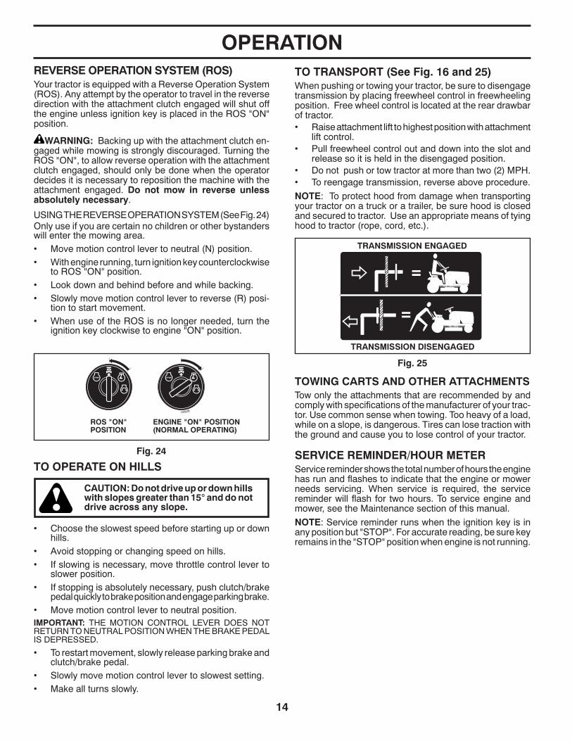
TO TRANSPORT (See Fig. 16 and 25)When pushing or towing your tractor, be sure to disengage transmission by placing freewheel control in free wheel ing po si tion. Free wheel control is located at the rear drawbar of tractor.• Raise attachment lift to highest position with at tach ment
lift control. • Pull freewheel control out and down into the slot and
release so it is held in the disengaged position.• Do not push or tow tractor at more than two (2) MPH.• To reengage transmission, reverse above procedure.
NOTE: To protect hood from damage when transporting your tractor on a truck or a trailer, be sure hood is closed and secured to tractor. Use an appropriate means of tying hood to tractor (rope, cord, etc.).
Fig. 25
Fig. 24
TOWING CARTS AND OTHER AT TACH MENTSTow only the attachments that are recommended by and comply with specifications of the manufacturer of your trac-tor. Use common sense when towing. Too heavy of a load, while on a slope, is dangerous. Tires can lose traction with the ground and cause you to lose control of your tractor.
SERVICE REMINDER/HOUR METERService reminder shows the total number of hours the engine has run and flashes to indicate that the engine or mower needs servicing. When service is required, the service reminder will flash for two hours. To service engine and mower, see the Maintenance section of this manual.
NOTE: Service reminder runs when the ignition key is in any position but "STOP". For accurate reading, be sure key remains in the "STOP" position when engine is not running.
TRANSMISSION ENGAGED
TRANSMISSION DISENGAGED
TO OPERATE ON HILLS
CAUTION: Do not drive up or down hills with slopes greater than 15° and do not drive across any slope.
• Choose the slowest speed before starting up or down hills.
• Avoid stopping or changing speed on hills.• If slowing is necessary, move throttle control lever to
slower position.• If stopping is absolutely necessary, push clutch/brake
pedal quickly to brake position and engage parking brake.• Move motion control lever to neutral position.IMPORTANT: THE MOTION CONTROL LEVER DOES NOT RETURN TO NEUTRAL POSITION WHEN THE BRAKE PED AL IS DEPRESSED.
• To restart movement, slowly release parking brake and clutch/brake pedal.
• Slowly move motion control lever to slowest setting.• Make all turns slowly.
OPERATIONREVERSE OPERATION SYSTEM (ROS)Your tractor is equipped with a Reverse Operation System (ROS). Any attempt by the operator to travel in the reverse direction with the attachment clutch engaged will shut off the engine unless ignition key is placed in the ROS "ON" position.
WARNING: Backing up with the attachment clutch en-gaged while mowing is strongly discouraged. Turning the ROS "ON", to allow reverse operation with the attachment clutch engaged, should only be done when the operator decides it is necessary to reposition the machine with the attachment engaged. Do not mow in reverse unless absolutely necessary.
USING THE REVERSE OPERATION SYSTEM (See Fig. 24)Only use if you are certain no children or other bystanders will enter the mowing area.• Move motion control lever to neutral (N) position.• With engine running, turn ignition key counterclockwise
to ROS "ON" position.• Look down and behind before and while backing.• Slowly move motion control lever to reverse (R) po si -
tion to start movement.• When use of the ROS is no longer needed, turn the
ignition key clockwise to engine "ON" position.
ROS "ON" POSITION
ENGINE "ON" POSITION(NORMAL OPERATING)
02828
15
ADD GASOLINE • Fill fuel tank to bottom of filler neck. Do not overfill.
Use fresh, clean, regular un lead ed gasoline with a minimum of 87 octane. (Use of leaded gasoline will increase carbon and lead oxide deposits and reduce valve life). Do not mix oil with gasoline. Purchase fuel in quan ti ties that can be used within 30 days to assure fuel freshness.
CAUTION: Wipe off any spilled oil or fuel. Do not store, spill or use gasoline near an open flame.
IMPORTANT: WHEN OPERATING IN TEMPERATURES BELOW 32°F (0°C), USE FRESH, CLEAN WINTER GRADE GAS O LINE TO HELP ENSURE GOOD COLD WEATHER START ING.
CAUTION: Alcohol blended fuels (called gasohol or using ethanol or methanol) can attract moisture which leads to sep a ra tion and for ma tion of acids during storage. Acidic gas can damage the fuel system of an engine while in storage. To avoid engine problems, the fuel system should be emptied before stor age of 30 days or longer. Drain the gas tank, start the engine and let it run until the fuel lines and carburetor are empty. Use fresh fuel next season. See Storage In struc tions for additional information. Never use engine or carburetor cleaner products in the fuel tank or permanent damage may occur.
OPERATIONBEFORE STARTING THE ENGINE
CHECK ENGINE OIL LEVELThe engine in your tractor has been shipped from the fac-tory already filled with sum mer weight oil.
• Check engine oil with tractor on level ground.• Remove oil fill cap/dipstick and wipe clean, reinsert the
dipstick and screw cap tight, wait for a few seconds, remove and read oil level. If necessary, add oil until “FULL” mark on dipstick is reached. Do not overfill.
• For cold weather operation you should change oil for easier starting. (See “OIL VISCOSITY CHART” in the Maintenance sec tion of this manual.)
• To change engine oil, see the Maintenance section in this manual.
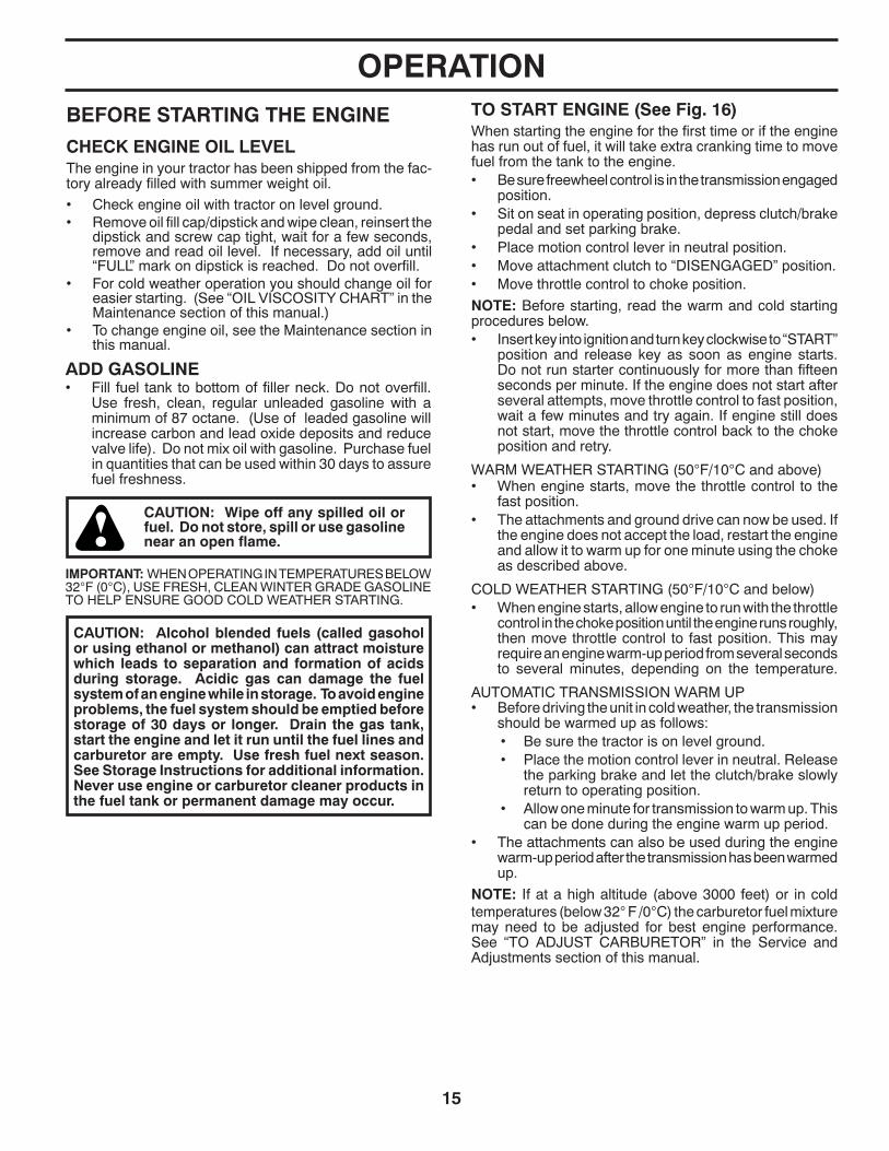
TO START ENGINE (See Fig. 16)When starting the engine for the first time or if the engine has run out of fuel, it will take extra cranking time to move fuel from the tank to the engine.• Be sure freewheel control is in the transmission en gaged
position.• Sit on seat in operating position, depress clutch/brake
pedal and set parking brake.• Place motion control lever in neutral position.• Move attachment clutch to “DISENGAGED” position.• Move throttle control to choke position.
NOTE: Before starting, read the warm and cold starting procedures below.• Insert key into ignition and turn key clockwise to “START”
position and release key as soon as engine starts. Do not run starter continuously for more than fifteen sec onds per minute. If the engine does not start after several attempts, move throttle control to fast position, wait a few minutes and try again. If engine still does not start, move the throttle control back to the choke position and retry.
WARM WEATHER STARTING (50°F/10°C and above)• When engine starts, move the throttle control to the
fast position.• The attachments and ground drive can now be used. If
the engine does not accept the load, restart the engine and allow it to warm up for one minute using the choke as described above.
COLD WEATHER STARTING (50°F/10°C and below)• When engine starts, allow engine to run with the throttle
control in the choke position until the engine runs roughly, then move throttle control to fast position. This may require an engine warm-up period from several seconds to several minutes, depending on the tem per a ture.
AUTOMATIC TRANSMISSION WARM UP• Before driving the unit in cold weather, the trans mis sion
should be warmed up as follows:• Be sure the tractor is on level ground.• Place the motion control lever in neutral. Re lease
the parking brake and let the clutch/brake slowly return to operating position.
• Allow one minute for transmission to warm up. This can be done during the engine warm up period.
• The attachments can also be used during the engine warm-up period after the transmission has been warmed up.
NOTE: If at a high altitude (above 3000 feet) or in cold temperatures (below 32° F /0°C) the carburetor fuel mixture may need to be adjusted for best engine performance. See “TO ADJUST CARBURETOR” in the Service and Adjustments section of this manual.
16
PURGE TRANSMISSION
CAUTION: Never engage or disengage freewheel lever while the engine is run ning.
To ensure proper operation and performance, it is rec om- mend ed that the transmission be purged before operating tractor for the first time. This procedure will remove any trapped air inside the transmission which may have de vel- oped during shipping of your tractor.IMPORTANT: SHOULD YOUR TRANSMISSION RE QUIRE REMOVAL FOR SERVICE OR REPLACEMENT, IT SHOULD BE PURGED AFTER REINSTALLATION BEFORE OPERATING THE TRACTOR.
1. Place tractor safely on a level surface - that is clear and open - with engine off and parking brake set.
2. Disengage transmission by placing freewheel control in freewheeling position (See “TO TRANSPORT” in this section of manual).
3. Sitting in the tractor seat, start engine. After the engine is running, move throttle control to slow position. With motion control lever in neutral po si tion, slowly disengage clutch/brake pedal.
CAUTION: At any time, during step 4, there may be movement of the drive wheels.
4. Move motion control lever to full forward position and hold for five (5) seconds. Move lever to full reverse position and hold for five (5) seconds. Repeat this procedure three (3) times.
5. Move motion control lever to neutral position. Shut- off engine and set parking brake.
6. Engage transmission by placing freewheel control in engaged position (See “TO TRANSPORT” in this sec- tion of manual).
7. Sitting in the tractor seat, start engine. After the engine is running, move throttle control to half (1/2) speed. With motion control lever in neutral position, slowly disengage clutch/brake pedal.
8. Slowly move motion control lever forward, after the tractor moves approximately five (5) feet, slowly move motion control lever to reverse position. After the trac-tor moves approximately five (5) feet return the motion control lever to the neutral position. Repeat this proce-dure with the motion control lever three (3) times.
Your transmission is now purged and now ready for normal op er a tion.
OPERATIONMOWING TIPS• Tire chains cannot be used when the mower hous ing
is attached to tractor.• Mower should be properly leveled for best mowing
performance. See “TO LEVEL MOWER HOUSING” in the Service and Adjustments section of this manual.
• The left hand side of mower should be used for trim ming.• Drive so that clippings are discharged onto the area
that has been cut. Have the cut area to the right of the tractor. This will result in a more even dis tri bu tion of clippings and more uniform cutting.
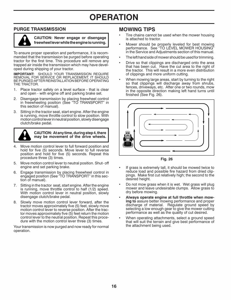
• When mowing large areas, start by turning to the right so that clippings will discharge away from shrubs, fences, driveways, etc. After one or two rounds, mow in the opposite direction making left hand turns until finished (See Fig. 26).
Fig. 26
• If grass is extremely tall, it should be mowed twice to reduce load and possible fire hazard from dried clip- pings. Make first cut relatively high; the second to the desired height.
• Do not mow grass when it is wet. Wet grass will plug mower and leave undesirable clumps. Allow grass to dry before mowing.
• Always operate engine at full throttle when mow-ing to assure better mowing performance and proper dis charge of material. Regulate ground speed by se lect ing a low enough gear to give the mower cut ting per for mance as well as the quality of cut desired.
• When operating attachments, select a ground speed that will suit the terrain and give best performance of the at tach ment being used.

17
LUBRICATION CHARTGENERAL RECOMMENDATIONSThe warranty on this tractor does not cover items that have been subjected to operator abuse or negligence. To receive full value from the warranty, operator must main tain tractor as instructed in this manual.Some adjustments will need to be made periodically to properly maintain your tractor.At least once a season, check to see if you should make any of the adjustments described in the Service and Adjustments section of this manual.
• At least once a year you should replace the spark plug, clean or replace air filter, and check blades and belts for wear. A new spark plug and clean air filter assure proper air-fuel mixture and help your engine run better and last longer.
BEFORE EACH USE• Check engine oil level.• Check brake operation.• Check tire pressure.• Check operator presence and ROS systems for proper
operation.• Check for loose fasteners.
IMPORTANT: DO NOT OIL OR GREASE THE PIVOT POINTS WHICH HAVE SPECIAL NYLON BEARINGS. VISCOUS LU BRI CANTS WILL ATTRACT DUST AND DIRT THAT WILL SHORT EN THE LIFE OF THE SELF-LU BRI CAT ING BEARINGS. IF YOU FEEL THEY MUST BE LU BRI CAT ED, USE ONLY A DRY, POW DERED GRAPHITE TYPE LU BRI CANT SPARINGLY.
➀ General Purpose Grease
➁ Refer to Maintenance “ENGINE” Section
02501
➀ MANDREL ZERKS
➁ ENGINE
➀ FRONT WHEEL BEARING ZERK
➀ STEERING SECTOR GEAR TEETH
➀ FRONT WHEEL BEARING ZERK
➀ SPINDLE ZERK ➀ SPINDLE ZERK
MAINTENANCE
TRACT0R
1 - Change more often when operating under a heavy load or in high ambient temperatures.
2 - Service more often when operating in dirty or dusty conditions.
ENGINE
3
2
2
2
2
3 - Replace blades more often when mowing in sandy soil.
4 - Not required if equipped with maintenance-free battery.
5 - See Cleaning in Maintenance Section.
1,
1,2
2
4
5
1,2
BEFOREEACHUSE
EVERY8
HOURS
EVERY25
HOURS
EVERY50
HOURS
EVERY100
HOURS
EVERYSEASON
BEFORESTORAGE
Inspect Muffler/Spark Arrester
Clean Air Filter
Change Engine Oil (with oil filter)
Replace Air Filter Paper Cartridge
Replace Spark Plug
Check Engine Oil Level
Clean Engine Cooling Fins
Clean Air Screen
Replace Oil Filter (If equipped)
Replace Fuel Filter
Change Engine Oil (without oil filter)
Lubrication Chart
Check Brake Operation
Check Battery Level
Check Tire Pressure
Clean Battery and Terminals
MAINTENANCE SCHEDULE
Check for Loose Fasteners
Check/Replace Mower Blades
Che
Clean Debris Off Steering Plate
ck Transaxle Cooling
Che
Check Operator Presence & ROS Systems
ck V-Belts
Check Mower Levelness
18
TRACTORAlways observe safety rules when per form ing any main te nance.
BRAKE OPERATIONIf tractor requires more than five (5) feet to stop at highest speed in high est gear on a level, dry concrete or paved surface, then brake must be checked and ad just ed. (See “TO CHECK BRAKE” in the Ser vice and Ad just ments section of this manual).
TIRES• Maintain proper air pressure in all tires (See the sides
of tires for proper PSI).• Keep tires free of gasoline, oil, or insect control
chemi cals which can harm rubber.• Avoid stumps, stones, deep ruts, sharp objects and
other hazards that may cause tire damage.
NOTE: To seal tire punctures and pre vent flat tires due to slow leaks, tire sealant may be purchased from your local parts dealer. Tire sealant also pre vents tire dry rot and corrosion.
OPERATOR PRESENCE SYS TEM AND REVERSE OPERATION SYSTEM (ROS) (See Fig. 27)Be sure operator presence and reverse operation sys tems are work ing properly. If your tractor does not function as described, repair the problem immediately.• The engine should not start unless the brake pedal is
fully de pressed, and the attachment clutch con trol is in the dis en gaged position.
CHECK OPERATOR PRESENCE SYSTEM• When the engine is running, any attempt by the op er a tor
to leave the seat without first setting the parking brake should shut off the engine.
• When the engine is running and the at tach ment clutch is engaged, any attempt by the operator to leave the seat should shut off the engine.
• The attachment clutch should never operate unless the operator is in the seat.
CHECK REVERSE OPERATION (ROS) SYSTEM• When the engine is running with the ignition switch in
the engine "ON" position and the at tach ment clutch engaged, any attempt by the operator to shift into reverse should shut off the engine.
• When the engine is running with the ignition switch in the ROS "ON" position and the at tach ment clutch engaged, any attempt by the operator to shift into reverse should NOT shut off the engine.
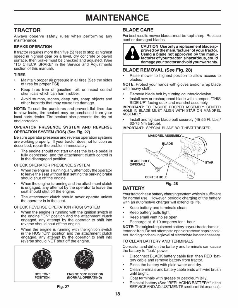
BLADE CAREFor best results mower blades must be kept sharp. Re place bent or damaged blades.
CAUTION: Use only a replacement blade ap-proved by the manufacturer of your tractor. Using a blade not approved by the manu-facturer of your tractor is hazardous, could damage your tractor and void your warranty.
BATTERYYour tractor has a battery charging system which is suf fi cient for normal use. However, periodic charging of the battery with an automotive charger will extend its life.• Keep battery and terminals clean.• Keep battery bolts tight.• Keep small vent holes open.• Recharge at 6-10 amperes for 1 hour.NOTE: The original equipment battery on your tractor is main-tenance free. Do not attempt to open or remove caps or cov-ers. Adding or checking level of electrolyte is not necessary.
TO CLEAN BATTERY AND TERMINALSCorrosion and dirt on the battery and terminals can cause the battery to “leak” power.• Disconnect BLACK battery cable first then RED bat-
tery cable and remove battery from tractor.• Rinse the battery with plain water and dry.• Clean terminals and battery cable ends with wire brush
until bright.• Coat terminals with grease or petroleum jelly.• Reinstall battery (See “REPLACING BATTERY" in the
SERVICE AND ADJUSTMENTS section of this man u al).Fig. 27
BLADE REMOVAL (See Fig. 28)• Raise mower to highest position to allow access to
blades.NOTE: Protect your hands with gloves and/or wrap blade with heavy cloth.• Remove blade bolt by turning counterclockwise.• Install new or resharpened blade with stamped "THIS
SIDE UP" facing deck and mandrel assembly.IMPORTANT: TO ENSURE PROPER ASSEMBLY, CENTER HOLE IN BLADE MUST ALIGN WITH STAR ON MANDREL ASSEMBLY.
• Install and tighten blade bolt securely (45-55 Ft. Lbs./62-75 Nm torque).
IMPORTANT: SPECIAL BLADE BOLT HEAT TREATED.
Fig. 28
BLADE
BLADE BOLT (SPECIAL)
CENTER HOLE
STAR
MANDREL ASSEMBLY
ROS "ON" POSITION
ENGINE "ON" POSITION(NORMAL OPERATING)
02828
MAINTENANCE
19
TRANSAXLE MAINTENANCEThe transmission fan and cooling fins should be kept clean to assure proper cooling.
Do not attempt to clean fan or transmission while engine is running or while the transmission is hot. To prevent pos- si ble damage to seals, do not use high pressure water or steam to clean transmission.• Inspect cooling fan to be sure fan blades are intact and
clean.• Inspect cooling fins for dirt, grass clippings and other
materials. To prevent damage to seals, do not use compressed air or high pressure sprayer to clean cool ing fins.
TRANSAXLE PUMP FLUID The transaxle was sealed at the factory and fluid main te- nance is not required for the life of the transaxle. Should the transaxle ever leak or require servicing, contact your near est au tho rized ser vice center/department.
V-BELTSCheck V-belts for deterioration and wear after 100 hours of operation and replace if necessary. The belts are not ad just able. Re place belts if they begin to slip from wear.
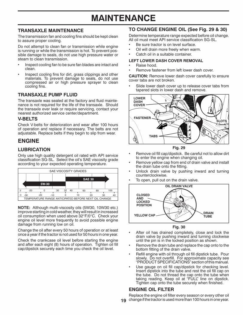
MAINTENANCETO CHANGE ENGINE OIL (See Fig. 29 & 30) Determine temperature range expected before oil change. All oil must meet API service classification SG-SL.• Be sure tractor is on level surface.• Oil will drain more freely when warm.• Catch oil in a suitable container.
LEFT LOWER DASH COVER REMOVAL• Raise hood.• Remove fastener from left lower dash cover.
CAUTION: Remove lower dash cover carefully to ensure cover tabs are not broken.
• Slide lower dash cover up to release cover tabs from tapered slots in lower dash and remove.
• Remove oil fill cap/dipstick. Be careful not to allow dirt to enter the engine when changing oil.
• Remove yellow cap from end of drain valve and install the drain tube onto the fitting.
• Unlock drain valve by pushing inward and turning coun ter clock wise.
• To open, pull out on the drain valve.
02463
CLOSED AND LOCKED POSITION
DRAIN TUBE
OIL DRAIN VALVE
YEL LOW CAP
ENGINE OIL FILTERReplace the engine oil filter every season or every other oil change if the tractor is used more than 100 hours in one year.
• After oil has drained completely, close and lock the drain valve by pushing inward and turning clockwise until the pin is in the locked position as shown.
• Remove the drain tube and replace the cap onto to the bottom fitting of the drain valve.
• Refill engine with oil through oil fill dipstick tube. Pour slowly. Do not overfill. For approximate capacity see “PRODUCT SPECIFICATIONS” section of this man u al.
• Use gauge on oil fill cap/dipstick for checking level. Insert dipstick into the tube and rest the oil fill cap on the tube. Do not thread the cap onto the tube when taking reading. Keep oil at “FULL” line on dipstick. Tighten cap onto the tube securely when finished.
Fig. 29
Fig. 30
TABS
SLOTSFASTENER
LOWER DASH COVER
TEMPERATURE RANGE ANTICIPATED BEFORE NEXT OIL CHANGE
SAE VISCOSITY GRADES
-20 0 30 40 80 100
-30 -20 0 20 30 40
F C
32
-10 10
60
5W-30
SAE 30
ENGINE
LUBRICATIONOnly use high quality detergent oil rated with API service classification SG-SL. Select the oil’s SAE viscosity grade according to your expected operating temperature.
NOTE: Although multi-viscosity oils (5W30, 10W30 etc.) improve starting in cold weather, they will result in increased oil consumption when used above 32°F/0°C. Check your engine oil level more frequently to avoid possible engine damage from running low on oil.
Change the oil after every 50 hours of operation or at least once a year if the tractor is not used for 50 hours in one year.
Check the crankcase oil level before starting the engine and after each eight (8) hours of operation. Tighten oil fill cap/dipstick securely each time you check the oil level.
20
00667FUEL FILTER
CLAMPCLAMP
IN-LINE FUEL FILTER (See Fig. 31)The fuel filter should be replaced once each season. If fuel filter becomes clogged, ob struct ing fuel flow to car bu re tor, re place ment is re quired.• With engine cool, remove filter and plug fuel line sec tions.• Place new fuel filter in position in fuel line with arrow
pointing towards carburetor.• Be sure there are no fuel line leaks and clamps are
properly positioned.• Immediately wipe up any spilled gasoline.
Fig. 31
MAINTENANCE
Fig. 32
• Keep finished surfaces and wheels free of all gasoline, oil, etc.
• Protect painted surfaces with automotive type wax.
We do not recommend using a garden hose or pressure washer to clean your tractor unless the engine and trans-mission are covered to keep water out. Water in engine or transmission will shorten the useful life of your tractor. Use compressed air or a leaf blower to remove grass, leaves and trash from tractor and mower.
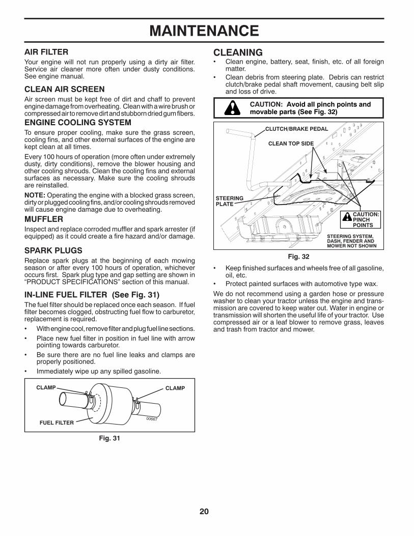
CLEANING• Clean engine, battery, seat, finish, etc. of all foreign
matter.• Clean debris from steering plate. Debris can restrict
clutch/brake pedal shaft movement, causing belt slip and loss of drive.
CAUTION: Avoid all pinch points and movable parts (See Fig. 32)
CLUTCH/BRAKE PEDAL
STEERING PLATE
STEERING SYSTEM, DASH, FENDER AND MOWER NOT SHOWN
CLEAN TOP SIDE
CAUTION:PINCH POINTS
ENGINE COOLING SYSTEMTo ensure proper cooling, make sure the grass screen, cooling fins, and other external surfaces of the engine are kept clean at all times.
Every 100 hours of operation (more often under extremely dusty, dirty conditions), remove the blower housing and other cooling shrouds. Clean the cooling fins and external surfaces as necessary. Make sure the cooling shrouds are reinstalled.
NOTE: Operating the engine with a blocked grass screen, dirty or plugged cooling fins, and/or cooling shrouds re moved will cause engine damage due to overheating.
AIR FILTER Your engine will not run properly using a dirty air filter. Service air cleaner more often under dusty conditions. See engine manual.
CLEAN AIR SCREEN Air screen must be kept free of dirt and chaff to prevent engine dam age from overheating. Clean with a wire brush or compressed air to re move dirt and stubborn dried gum fibers.
MUFFLER Inspect and replace corroded muffler and spark arrester (if equipped) as it could create a fire hazard and/or damage.
SPARK PLUGS Replace spark plugs at the beginning of each mowing season or after every 100 hours of operation, whichever occurs first. Spark plug type and gap setting are shown in “PROD UCT SPECIFICATIONS” section of this manual.
21
MAINTENANCEDECK WASHOUT PORT (See Fig. 33)Your tractor’s deck is equipped with a washout port on its surface as part of its deck wash system. It should be utilized after each use. 1. Drive the tractor to a level, clear spot on your lawn, near
enough to a water spigot for your garden hose to reach.
IMPORTANT: Make certain the tractor’s discharge chute is directed AWAY from your house, garage, parked cars, etc. Remove bagger chute or mulch cover if attached.
2. Make sure the attachment clutch control is in the “DIS EN GAGED” position, set the parking brake, and stop the engine.
3. Thread the nozzle adapter (packaged with your tractor’s Operator’s Manual) onto the end of your garden hose.
4. Pull back the lock collar of the nozzle adapter and push the adapter onto the deck washout port at the left end of the mower deck. Release the lock collar to lock the adapter on the nozzle.
WASHOUT PORT
NOZZLE ADAPTER
HOSE
IMPORTANT: Tug hose ensuring connection is secure.5. Turn the water on.6. While sitting in the operator’s position on the tractor,
re-start the engine and place the throttle lever in the Fast " " position.
IMPORTANT: Recheck the area making certain the area is clear. 7. Move the tractor’s attachment clutch control to the
“ENGAGED” position. Remain in the operator’s position with the cutting deck engaged until the deck is cleaned.
8. Move the tractor’s attachment clutch control to the “DIS- EN GAGED” position. Turn the ignition key to the STOP position to turn the tractor’s engine off. Turn the water off.
9. Pull back the lock collar of the nozzle adapter to dis-connect the adapter from the nozzle washout port.
10. Move the tractor to a dry area, preferably a concrete or paved area. Place the attachment clutch control in the “ENGAGED” position to remove excess water and to help dry before putting the tractor away.
WARNING: A broken or missing washout fitting could expose you or others to thrown objects from contact with the blade.
• Replace broken or missing washout fitting immediately, prior to using mower again.
• Plug any holes in mower with bolts and locknuts.
Fig. 33

22Fig. 34 Fig. 35
E
A
M FB
K
CC
S
H
DD
L
TO REPLACE MOWER BLADE DRIVE BELT (See Fig. 35)MOWER DRIVE BELT REMOVAL• Park tractor on a level surface. En gage parking brake.• Lower attachment lift lever to its lowest position.• Disengage belt tension rod (K) from lock bracket (L).
CAUTION: Belt tension rod is spring loaded. Have a firm grip on rod and release slowly.
• Remove screws (P) from mandrel covers (Q) and remove covers.
• Remove any dirt or grass clippings which may have accu-mulated around mandrels and entire upper deck surface.
• Remove belt from electric clutch pulley (M), both man-drel pulleys (R) and all idler pulleys (V).
MOWER DRIVE BELT INSTALLATION • Install belt around all mandrel pulleys (R) and around
idler pulleys (V) as shown.• Install belt onto electric clutch pulley (M).
IMPORTANT: Check belt for proper routing in all mower pulley grooves.• Reassemble mandrel covers (Q). Securely tighten all
screws.• Engage belt tension rod (K) on locking bracket (L).
CAUTION: Belt tension rod is spring loaded. Have a firm grip on rod and release slowly.
• Raise attachment lift lever to highest position.
V
Q
P
M
K
L
R
P
Q
R
P
R
WARNING: TO AVOID SE RI OUS IN JU RY, BEFORE PERFORMING ANY SERVICE OR ADJUSTMENTS:• Depress brake pedal fully and set parking brake.• Place motion control lever in neutral position.• Place attachment clutch in “DISENGAGED” position.• Turn ignition key to “STOP” and remove key.• Make sure the blades and all moving parts have completely stopped.• Disconnect spark plug wire from spark plug and place wire where it cannot come in contact with plug.
TO REMOVE MOWER (See Fig. 34)• Place attachment clutch in “DIS EN GAGED” position.• Lower attachment lift lever to its lowest position.• Disengage belt tension rod (K) from lock bracket (L).
CAUTION: Belt tension rod is spring loaded. Have a tight grip on rod and release slowly.
• Remove mower belt from electric clutch pulley (M).• Disconnect front link (E) from mower - remove retainer
spring and washer.• Go to either side of mower and disconnect mower suspen-
sion arm (A) from chassis and rear lift link (C) from rear mower bracket (D) - remove retainer springs and washers.
• Go to other side of mower and disconnect the suspen-sion arm and rear lift link.
CAUTION: After rear lift links are discon-nected, the attachment lift lever will be spring loaded. Have a tight grip on lift lever when changing position of the lever.
• From right side of mower, disconnect anti-sway bar (S) from right rear mower bracket (D) - remove retainer spring and washer and pull mower toward you until the bar falls from the hole in bracket.
• Turn tractor steering wheel to the left as far as it will go.• Slide mower out from under right side of tractor.
TO IN STALL MOWERFollow procedure described in “INSTALL MOWER AND DRIVE BELT” in the As sem bly section of this manual.
SERVICE AND ADJUSTMENTS

23
FRONT-TO-BACK ADJUSTMENT (See Figs. 38 & 39)IMPORTANT: Deck must be level side-to-side.
To obtain the best cutting re sults, the mower blades should be adjusted so the front tip is 1/8" to 1/2" lower than the rear tip when the mower is in its highest position.
CAUTION: Blades are sharp. Protect your hands with gloves and/or wrap blade with heavy cloth.
• Raise mower to highest position.
• Position any blade so the tip is pointing straight forward. Measure distance (B) to the ground at front and rear tip of the blade.
TO LEVEL MOWERMake sure tires are properly inflated to the PSI shown on tires. If tires are over or under inflated, it may affect the appearance of your lawn and lead you to think the mower is not adjusted properly.
VISUAL SIDE-TO-SIDE ADJUSTMENT (See Fig. 36)• With all tires properly inflated and if your lawn appears
unevenly cut, determine which side of mower is cutting lower.
NOTE: As desired, you can raise the low side of mower or lower the high side.
• Go to side of mower you wish to adjust.
• With a 3/4" or adjustable wrench, turn lift link adjust-ment nut (A) to the left to lower the mower, or, to the right to raise the mower.
NOTE: Each full turn of adjustment nut will change mower height about 3/16".
• Test your adjustment by mowing some uncut grass and visually checking the appearance. Readjust, if necessary, until you are satisfied with the results.
A
Turn nut leftto lower mower
Turn nut rightto raise mower
Fig. 36
Fig. 37
PRECISION SIDE-TO-SIDE ADJUSTMENT (See Fig. 37)• With all tires properly inflated, park tractor on level
ground or driveway.
CAUTION: Blades are sharp. Protect your hands with gloves and/or wrap blade with heavy cloth.
• Raise mower to its highest position.
• At both sides of mower, position blade at side and measure the distance (A) from bottom edge of blade to the ground. The distance should be the same on both sides.
NOTE: Each full turn of the adjustment nut will change mower height about 1/8".
• Recheck measurements, adjust if necessary until front tip of blade is 1/8" to 1/2" lower than the rear tip.
• Hold adjustment nut in position with wrench and tighten jam nut securely against adjustment nut.
B B
Fig. 38
Fig. 39
02966
A A
• If adjustment is necessary, see steps in Visual Adjust-ment instructions above.
• Recheck measurements, adjust if necessary until both sides are equal.
B
02950
A
TIGHTEN ADJUST NUT B TO RAISE MOWER
LOOSEN ADJUST NUT B TO LOWER
MOWERLOOSEN JAM NUT A FIRST
• If front tip of blade is not 1/8" to 1/2" lower than the rear tip, go to the front of tractor.
• With an 11/16" or adjustable wrench, loosen jam nut A several turns to clear adjustment nut B.
• With a 3/4" or adjustable wrench, turn front link adjustment nut (B) clockwise (tighten) to raise the front of mower, or, counterclockwise (loosen) to lower the front mower.
SERVICE AND ADJUSTMENTS

24Fig. 40
TO REMOVE WHEEL (See Fig. 41)• Block up axle securely.• Remove axle cover, retaining ring and washers to allow
wheel removal (rear wheel contains a square key - Do not lose).
• Repair tire and reassemble.• On rear wheels only: align grooves in rear wheel hub
and axle. Insert square key.• Replace washers and snap retaining ring securely in
axle groove.• Replace axle cover.NOTE: To seal tire punctures and prevent flat tires due to slow leaks, tire sealant may be purchased from your local parts dealer. Tire sealant also prevents tire dry rot and corrosion.
Fig. 41
RE TAIN ING RING
WASH ERS
SQUARE KEY (REAR WHEEL ONLY)
AXLE COVER
TO CHECK BRAKE If tractor requires more than five (5) feet to stop at highest speed in high est gear on a level, dry concrete or paved surface, then brake must be serviced.
You may also check brake by:• Park tractor on a level, dry concrete or paved surface,
depress brake pedal all the way down and engage parking brake.
• Disengage transmission by placing freewheel control in “transmission disengaged” position. Pull freewheel control out and into the slot and release so it is held in the disengaged position.
The rear wheels must lock and skid when you try to manu-ally push the tractor forward. If the rear wheels rotate, then the brake needs to be serviced. Contact a qualified service center.
FRONT WHEEL TOE-IN/CAMBERYour new tractor front wheel toe-in and camber is set at the factory and is normal. The front wheel toe-in and camber are not adjustable. If damage has occurred to affect the factory set front wheel toe-in or camber, contact a qualified service center.
TO REPLACE MOTION DRIVE BELT(See Fig. 40)Park the tractor on level surface. En gage parking brake. For as sis tance, there is a belt installation guide decal on bottom side of left footrest.BELT REMOVAL -
1. Remove mower (See “TO REMOVE MOWER” section in this manual).
NOTE: Observe entire motion drive belt and position of all belt guides and keepers.
2. Disconnect clutch wire harness (A).3. Remove anti-rotation link (B) on right side of tractor.4. Remove belt from stationary idler (C) and clutching idler (D).5. Remove belt from centerspan idler (E).6. Pull belt slack toward rear of trac tor. Carefully remove
belt up wards from trans mis sion input pulley and over cooling fan blades (F).
7. Remove belt downward from engine pulley and around electric clutch (G).
8. Slide belt toward rear of tractor, off the steering plate (H) and remove from tractor.
BELT INSTALLATION -
1. Install new belt from tractor rear to front, over the steer-ing plate (H) and above clutch brake pedal shaft (J).
2. Pull belt toward front of tractor and roll belt around electric clutch and onto engine pulley (G).
3. Pull belt toward rear of tractor. Carefully work belt down around transmission cooling fan and onto the input pul-ley (F). Be sure belt is inside the belt keeper.
4. Install belt on centerspan idler (E).5. Install belt through stationary idler (C) and clutch ing idler (D).6. Reinstall anti-rotation link (B) on right side of tractor.
Tighten securely.7. Reconnect clutch harness (A).8. Make sure belt is in all pulley grooves and in side all belt
guides and keep ers.9. Install mower (See “TO INSTALL MOWER” section in
this manual).
electric02953
E
A
F
B
J
G
C
H
D
SERVICE AND ADJUSTMENTS
25
TO START ENGINE WITH A WEAK BATTERY (See Fig. 43)
WARNING: Lead-acid batteries gen- er ate ex plo sive gases. Keep sparks, flame and smoking ma te ri als away from bat ter ies. Always wear eye pro tec tion when around batteries.
If your battery is too weak to start the engine, it should be recharged. (See "BATTERY" in the MAINTENANCE sec- tion of this man u al).If “jumper ca bles” are used for emer gen cy starting, follow this pro ce dure:IMPORTANT: YOUR TRACTOR IS EQUIPPED WITH A 12 VOLT SYSTEM. THE OTHER VEHICLE MUST ALSO BE A 12 VOLT SYSTEM. DO NOT USE YOUR TRACTOR BATTERY TO START OTHER VEHICLES.
TO ATTACH JUMPER CABLES - • Connect one end of the RED cable to the POSITIVE
(+) terminal of each battery(A-B), taking care not to short against tractor chassis.
• Connect one end of the BLACK ca ble to the NEGA TIVE (-) terminal (C) of fully charged battery.
• Connect the other end of the BLACK cable (D) to good chassis ground, away from fuel tank and bat tery.
TO REMOVE CABLES, REVERSE ORDER - • BLACK cable first from chassis and then from the fully
charged battery. • RED cable last from both batteries.
Fig. 43
WEAK OR DEADBATTERY
FULLY CHARGEDBATTERY
ADJUSTMENT BOLT
NEUTRAL LOCK GATE
MOTION CONTROL LEVER
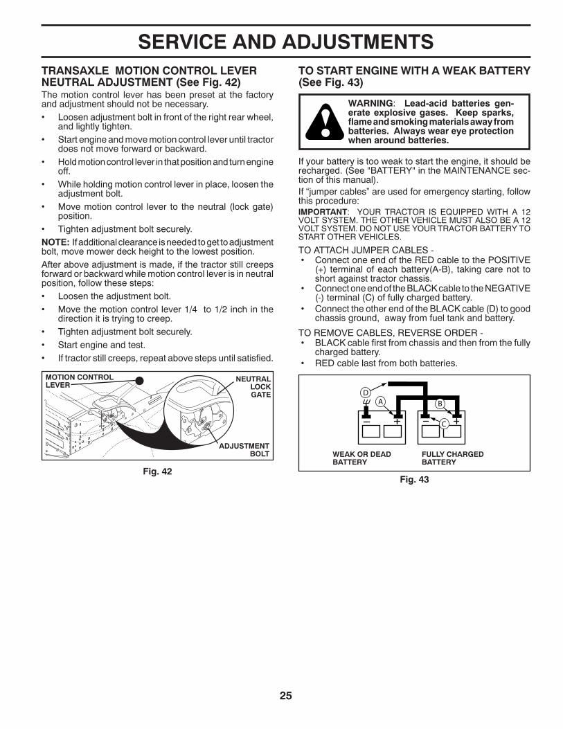
Fig. 42
TRANSAXLE MOTION CONTROL LEVER NEUTRAL ADJUSTMENT (See Fig. 42)The motion control lever has been pre set at the factory and adjustment should not be necessary.• Loosen adjustment bolt in front of the right rear wheel,
and lightly tighten.• Start engine and move motion control lever until tractor
does not move forward or backward.• Hold motion control lever in that position and turn engine
off.• While holding motion control lever in place, loosen the
adjustment bolt.• Move motion control lever to the neutral (lock gate)
position.• Tighten adjustment bolt securely.NOTE: If additional clearance is needed to get to ad just ment bolt, move mower deck height to the lowest position.After above adjustment is made, if the tractor still creeps forward or backward while motion control lever is in neutral position, follow these steps:• Loosen the adjustment bolt.• Move the motion control lever 1/4 to 1/2 inch in the
direction it is trying to creep.• Tighten adjustment bolt securely.• Start engine and test.• If tractor still creeps, repeat above steps until satisfied.
SERVICE AND ADJUSTMENTS

26
TO REPLACE HEADLIGHT BULB• Raise hood.• Pull bulb holder out of the hole in the backside of the
grill.• Replace bulb in holder and push bulb holder securely
back into the hole in the backside of the grill.• Close hood.
INTERLOCKS AND RELAYSLoose or damaged wiring may cause your tractor to run poorly, stop running, or prevent it from starting.• Check wiring.
TO REPLACE FUSEReplace with 20 amp automotive-type plug-in fuse. The fuse holder is located behind the dash.
TO REMOVE HOOD AND GRILL ASSEMBLY (See Fig. 45)• Raise hood.• Unsnap headlight wire connector.• Stand in front of tractor. Grasp hood at sides, tilt toward
engine and lift off of tractor.• To replace, reverse above procedure.
ENGINE
TO AD JUST THROTTLE CON TROL CABLE The throttle control has been preset at the factory and ad just ment should not be necessary. If adjustment is nec- es sary, see engine manual.
TO AD JUST CHOKE CON TROL The choke control has been preset at the factory and ad just- ment should not be necessary. If adjustment is necessary, see engine manual.
TO ADJUST CARBURETOR Your carburetor is not adjustable. If your engine does not operate properly due to suspected carburetor problems, take your tractor to an authorized service center for repair and/or adjustment.
Fig. 45
TRANSMISSION
REMOVAL/RE PLACE MENTShould your transmission require removal for service or re place ment, it should be purged after reinstallation and before operating the tractor. See “PURGE TRANS MIS SION” in the Operation section of this manual.
REPLACING BATTERY (See Fig. 44)
WARNING: Do not short battery ter mi- nals by allowing a wrench or any other object to contact both terminals at the same time. Before connecting battery, remove metal bracelets, wristwatch bands, rings, etc. Positive terminal must be connected first to prevent sparking from ac ci den tal grounding.
• Lift hood to raised position.• Remove terminal cover.• Disconnect BLACK battery cable then RED battery
cable and carefully remove battery from tractor.• Install new battery with terminals in same position as
old battery.• Reinstall terminal cover.• First connect RED battery cable to positive (+) battery
terminal with bolt and nut as shown. Tighten securely.• Connect BLACK grounding cable to negative (-) bat tery
terminal with remaining bolt and nut. Tighten securely• Close hood.
POSITIVE(RED)CABLE
TERMINAL COVER
NEGATIVE (BLACK)
CABLE
Fig. 44
SERVICE AND ADJUSTMENTS
HEADLIGHTWIRECONNECTOR
HOOD
03076
27
Immediately prepare your tractor for storage at the end of the season or if the tractor will not be used for 30 days or more.
WARNING: Never store the trac tor with gas o line in the tank inside a building where fumes may reach an open flame or spark. Allow the engine to cool before storing in any en clo sure.
TRACTORRemove mower from tractor for winter storage. When mower is to be stored for a period of time, clean it thor- oughly, remove all dirt, grease, leaves, etc. Store in a clean, dry area.• Clean entire tractor (See “CLEANING” in the Mainte-
nance section of this manual).• Inspect and replace belts, if necessary (See belt re-
place ment instructions in the Service and Adjustments section of this manual).
• Lubricate as shown in the Maintenance sec tion of this man ual.
• Be sure that all nuts, bolts and screws are securely fastened. Inspect moving parts for damage, breakage and wear. Replace if necessary.
• Touch up all rusted or chipped paint surfaces; sand lightly before painting.
BATTERY• Fully charge the battery for storage.• After a period of time in storage, battery may require
re charg ing.• To help prevent corrosion and power leakage during
long periods of storage, battery cables should be dis- con nect ed and battery cleaned thoroughly (see “TO CLEAN BATTERY AND TERMINALS” in the Mainte-nance section of this manual).
• After cleaning, leave cables disconnected and place cables where they cannot come in contact with battery terminals.
• If battery is removed from tractor for storage, do not store battery directly on concrete or damp surfaces.
ENGINE
FUEL SYSTEMIMPORTANT: IT IS IMPORTANT TO PREVENT GUM DEPOSITS FROM FORMING IN ES SEN TIAL FUEL SYSTEM PARTS SUCH AS CARBURETOR, FUEL FIL TER, FUEL HOSE, OR TANK DURING STORAGE. ALSO, EXPERIENCE INDICATES THAT ALCOHOL BLENDED FUELS (CALLED GASOHOL OR USING ETHANOL OR METHANOL) CAN ATTRACT MOIS TURE WHICH LEADS TO SEPARATION AND FOR MA TION OF ACIDS DURING STOR AGE. ACIDIC GAS CAN DAMAGE THE FUEL SYSTEM OF AN ENGINE WHILE IN STORAGE.• Empty the fuel tank by starting the engine and let it run
until the fuel lines and carburetor are empty.• Never use engine or carburetor cleaner products in
the fuel tank or permanent damage may occur.• Use fresh fuel next season.
NOTE: Fuel stabilizer is an acceptable alternative in mini-mizing the formation of fuel gum deposits during stor age. Add stabilizer to gasoline in fuel tank or storage container. Always follow the mix ratio found on stabilizer container. Run engine at least 10 minutes after adding stabilizer to allow the stabilizer to reach the carburetor. Do not empty the gas tank and carburetor if using fuel stabilizer.
ENGINE OILDrain oil (with engine warm) and replace with clean engine oil. (See “ENGINE” in the Maintenance section of this man ual).
CYLINDER(S)• Remove spark plug(s).• Pour one ounce of oil through spark plug hole(s) into
cylinder(s).• Turn ignition key to “START” position for a few seconds
to distribute oil.• Replace with new spark plug(s).
OTHER• Do not store gasoline from one season to another.• Replace your gasoline can if your can starts to rust.
Rust and/or dirt in your gasoline will cause problems.• If possible, store your tractor indoors and cover it to
give protection from dust and dirt.• Cover your tractor with a suitable protective cover that
does not retain moisture. Do not use plastic. Plastic cannot breathe which allows condensation to form and will cause your tractor to rust.
IMPORTANT: NEVER COVER TRACTOR WHILE EN GINE AND EXHAUST AREAS ARE STILL WARM.
STORAGE

28
TROUBLESHOOTING POINTSPROBLEM CAUSE CORRECTION
Will not start 1. Out of fuel. 1. Fill fuel tank.2. Engine not “CHOKED” properly. 2. See “TO START ENGINE” in Operation section.3. Engine flooded. 3. Wait several minutes before attempting to start.4. Bad spark plug. 4. Replace spark plug.5. Dirty air filter. 5. Clean/replace air filter.6. Dirty fuel filter. 6. Replace fuel filter.7. Water in fuel. 7. Empty fuel tank and carburetor, refill tank with fresh
gasoline and replace fuel filter.8. Loose or damaged wiring. 8. Check all wiring.9. Carburetor out of adjustment. 9. See “To Adjust Carburetor” in Service Adjustments
section.10. Engine valves out of adjustment. 10. Contact an authorized service center/department.
Hard to start 1. Dirty air filter. 1. Clean/replace air filter.2. Bad spark plug. 2. Replace spark plug.3. Weak or dead battery. 3. Recharge or replace battery.4. Dirty fuel filter. 4. Replace fuel filter.5. Stale or dirty fuel. 5. Empty fuel tank and refill tank with fresh, clean gas.6. Loose or damaged wiring. 6. Check all wiring.7. Carburetor out of adjustment. 7. See “To Adjust Carburetor” in Service Adjustments
section.8. Engine valves out of adjustment. 8. Contact an authorized service center/department.
Engine will not turn over
1. Brake pedal not depressed. 1. Depress brake pedal.2. Attachment clutch is engaged. 2. Disengage attachment clutch.3. Weak or dead battery. 3. Recharge or replace battery.4. Blown fuse. 4. Replace fuse.5. Corroded battery terminals. 5. Clean battery terminals.6. Loose or damaged wiring. 6. Check all wiring.7. Faulty ignition switch. 7. Check/replace ignition switch.8. Faulty solenoid or starter. 8. Check/replace solenoid or starter.9. Faulty operator presence switch(es). 9. Contact an authorized service center/department.
Engine clicks but will not start
1. Weak or dead battery. 1. Recharge or replace battery.2. Corroded battery terminals. 2. Clean battery terminals.3. Loose or damaged wiring. 3. Check all wiring.4. Faulty solenoid or starter. 4. Check/replace solenoid or starter.
Loss of power 1. Cutting too much grass/too fast. 1. Raise cutting height/reduce speed.2. Throttle in “CHOKE” position. 2. Adjust throttle control.3. Build-up of grass, leaves, trash under mower. 3. Clean underside of mower housing.4. Dirty air filter. 4. Clean/replace air filter.5. Low oil level/dirty oil. 5. Check oil level/change oil.6. Faulty spark plug. 6. Clean and regap or change spark plug.7. Dirty fuel filter. 7. Replace fuel filter.8. Stale or dirty fuel. 8. Empty fuel tank and refill tank with fresh, clean gas.9. Water in fuel. 9. Empty fuel tank and carburetor, refill tank with fresh
gasoline and replace fuel filter.10. Spark plug wire loose. 10. Connect and tighten spark plug wire.11. Dirty engine air screen/fins. 11. Clean engine air screen/fins.12. Dirty/clogged muffler. 12. Clean/replace muffler.13. Loose or damaged wiring. 13. Check all wiring.14. Carburetor out of adjustment. 14. See “To Adjust Carburetor” in Service Adjustments 15. Engine valves out of adjustment. 15. Contact an authorized service center/department.
Excessive vibration
1. Worn, bent or loose blade. 1. Replace blade. Tighten blade bolt.2. Bent blade mandrel. 2. Replace blade mandrel.3. Loose/damaged part(s). 3. Tighten loose part(s). Replace damaged parts.

29
TROUBLESHOOTING POINTSPROBLEM CAUSE CORRECTION
Engine continues to run when oper-ator leaves seat with attachment clutch engaged
1. Faulty operator-safety presence control system.
1. Check wiring, switches and connections. If not corrected, contact an authorized service center/ department.
Poor cut - uneven 1. Worn, bent or loose blade. 1. Replace blade. Tighten blade bolt.2. Mower deck not level. 2. Level mower deck.3. Buildup of grass, leaves, trash under mower. 3. Clean underside of mower housing.4. Bent blade mandrel. 4. Replace blade mandrel.5. Clogged mower deck vent holes from
buildup of grass, leaves, and trash around mandrels.
5. Clean around mandrels to open vent holes.
Mower blades will not rotate
1. Obstruction in clutch mechanism. 1. Remove obstruction.2. Worn/damaged mower drive belt. 2. Replace mower drive belt.3. Frozen idler pulley. 3. Replace idler pulley.4. Frozen blade mandrel. 4. Replace blade mandrel.
Poor grass discharge
1. Engine speed too slow. 1. Place throttle control in “FAST” position.2. Travel speed too fast. 2. Shift to slower speed.3. Wet grass. 3. Allow grass to dry before mowing.4. Mower deck not level. 4. Level mower deck.5. Low/uneven tire air pressure. 5. Check tires for proper air pressure.6. Worn, bent or loose blade. 6. Replace blade. Tighten blade bolt.7. Buildup of grass, leaves, trash under mower. 7. Clean underside of mower housing.8. Mower drive belt worn. 8. Replace mower drive belt.9. Blades improperly installed. 9. Reinstall blades sharp edge down.
10. Improper blades used. 10. Replace with blades listed in parts manual.11. Clogged mower deck vent holes from buildup
of grass, leaves, trash around mandrels.11. Clean around mandrels to open vent holes.
Headlight(s) not working(if so equipped)
1. Switch is “OFF”. 1. Turn switch “ON”.2. Bulb(s) or lamp(s) burned out. 2. Replace bulb(s) or lamp(s).3. Faulty light switch. 3. Check/replace light switch.4. Loose or damaged wiring. 4. Check wiring and connections.5. Blown fuse. 5. Replace fuse.
Battery will not charge
1. Bad battery cell(s). 1. Replace battery.2. Poor cable connections. 2. Check/clean all connections.3. Faulty regulator (if so equipped). 3. Replace regulator.4. Faulty alternator. 4. Replace alternator.
Loss of drive 1. Freewheel control in “disengaged” position. 1. Place freewheel control in “engaged” position.2. Debris on steering plate (if equipped). 2. See "CLEANING" in the maintenance section.3. Motion drive belt worn, damaged, or broken. 3. Replace motion drive belt.4. Air trapped in transmission during shipment
or servicing.4. Purge transmission.
5. Axle key missing. 5. Install axle key at rear wheel. See "TO REMOVE WHEEL" in the Service and Adjustments section.
Engine "back-fires” when turn-ing engine “OFF”
1. Engine throttle control not set between half and full speed (fast) position before stopping engine.
1. Move throttle control between half and full speed (fast) position before stopping engine.
Engine dies when tractor is shifted into reverse
1. Reverse operation system (ROS) is not "ON" while mower or other attachment is engaged.
1. Turn ignition key to ROS "ON" position. See Operation section.

30
15 D
EG
RE
ES
MA
X.
FOLD
ALO
NG
DO
TTE
D L
INE
THIS
IS A
15
DE
GR
EE
SLO
PE
ON
LY
RID
E U
P A
ND
DO
WN
HIL
L,
NO
T A
CR
OS
S H
ILL
SU
GG
ES
TE
D G
UID
E F
OR
SIG
HT
ING
SL
OP
ES
FO
R S
AF
E O
PE
RA
TIO
N
WA
RN
ING
: T
o a
void
ser
iou
s in
jury
, op
erat
e yo
ur
trac
tor
up
an
d
do
wn
th
e fa
ce o
f sl
op
es, n
ever
acr
oss
th
e fa
ce. D
o n
ot
mo
wsl
op
es g
reat
er t
han
15
deg
rees
. Mak
e tu
rns
gra
du
ally
to
pre
ven
tti
pp
ing
or
loss
of
con
tro
l. E
xerc
ise
extr
eme
cau
tio
n w
hen
chan
gin
g d
irec
tio
n o
n s
lop
es.
1. F
old
th
is p
age
alo
ng
do
tted
lin
e in
dic
ated
ab
ove
.2.
Ho
ld p
age
bef
ore
yo
u s
o t
hat
its
left
ed
ge
is v
erti
cally
par
alle
l to
a t
ree
t
run
k o
r o
ther
up
rig
ht
stru
ctu
re.
3. S
igh
t ac
ross
th
e fo
ld in
th
e d
irec
tio
n o
f h
ill s
lop
e yo
u w
ant
to m
easu
re.
4. C
om
par
e th
e an
gle
of
the
fold
wit
h t
he
slo
pe
of
the
hill
.

31
Consumer Wheeled Products - Limited Warranty
Husqvarna warrants to the original retail purchaser that this product is free from defects in material or workmanship under normal useand maintenance from the date of retail purchase for the applicable Warranty Period shown on Exhibit A. This Limited Warranty may not be transferredto any subsequent purchaser of this product. Certain components (e.g., engines and transmissions) are excluded from coverage, and otherlimitations apply, as described in this document. Husqvarna will repair or replace at its discretion, any defective product or part covered by the LimitedWarranty, free of charge at any authorized Husqvarna Servicing Dealer/Center using original OEM Husqvarna replacement parts, subject to thelimitations and exclusions described below. Husqvarna does not offer an over-the-counter exchange program.
DISCLAIMERS, LIMITATIONS AND EXCLUSIONS
1. WARRANTY DISCLAIMER. THIS LIMITED WARRANTY IS THE SOLE EXPRESS WARRANTY PROVIDED BY HUSQVARNA AND THERE ARE NOWARRANTIES WHICH EXTEND BEYOND THE DESCRIPTION ON THE FACE HEREOF, EXCEPT AS MAY BE PROVIDED BY LAW. THIS WARRANTY ISGIVEN ONLY BY HUSQVARNA, AND MAY BE MODIFIED ONLY BY HUSQVARNA. THIS LIMITED WARRANTY IS THE FINAL EXPRESSION OF OURAGREEMENT, AND IS A COMPLETE AND EXCLUSIVE STATEMENT OF THE TERMS OF THAT AGREEMENT. THIS LIMITED WARRANTY GIVES YOUSPECIFIC LEGAL RIGHTS, AND YOU MAY ALSO HAVE OTHER RIGHTS WHICH VARY BASED ON LOCALITY
2. LIMITED DURATION. ANY WARRANTY THAT MAY BE IMPLIED BY LAW (INCLUDING ANY IMPLIED WARRANTY OF FITNESS FOR APARTICULAR PURPOSE OR USE AND IMPLIED WARRANTY OF MERCHANTABILITY) IS LIMITED TO THE DURATION OF THE APPLICABLEWARRANTY PERIOD UNDER THIS LIMITED WARRANTY. SOME LOCALITIES DO NOT ALLOW LIMITATIONS ON HOW LONG AN IMPLIEDWARRANTY LASTS, SO THE ABOVE LIMITATIONS MAY NOT APPLY TO YOU.
3. EXCLUSIVE REMEDIES. SOME LOCALITIES, INCLUDING THE PROVINCE OF QUEBEC, DO NOT ALLOW THE EXCLUSION OR LIMITATION OFLIABILITY FOR INJURY TO PERSON OR FOR DAMAGES RESULTING FROM THE FAULT OF THE MANUFACTURER AND/OR THE EXCLUSION ORLIMITATION OF INCIDENTAL OR CONSEQUENTIAL DAMAGES. AS SUCH, SOME OF THE FOLLOWING LIMITATIONS MAY NOT APPLY TO YOU. THEABOVE REMEDIES ARE THE EXCLUSIVE REMEDIES FOR ANY BREACH OF THIS LIMITED WARRANTY. NO OTHER REMEDY, INCLUDING, BUT NOTLIMITED TO ANY SPECIAL, INCIDENTAL, INDIRECT OR CONSEQUENTIAL DAMAGES, FOR LOST PROFITS, LOST SALES, INJURY TO PERSON ORPROPERTY, OR ANY OTHER INCIDENTAL OR CONSEQUENTIAL LOSS SHALL BE AVAILABLE, AND ALL SUCH DAMAGES ARE HEREBYDISCLAIMED.
4. Engines, Transmissions and certain other components are NOT covered. This Limited Warranty does not cover any of the following:
(a) Engines and Attachments.Except where otherwise indicated on Exhibit A, all Engines and Attachments are not covered by this Limited Warranty. In most cases, theseitems are NOT manufactured by Husqvarna in which case they may be covered separately by their respective manufacturer's warranties if one is provided and included withthe product at the time of purchase. All such claims must be submitted and sent to the appropriate manufacturer or as otherwise directed in those separate warranties.Husqvarna is not authorized to handle warranty adjustments or repairs on engines manufactured by Briggs & Stratton, Honda, Kawasaki, or Kohler (with the exception ofmodels equipped with LCT engines). Husqvarna does not assume any warranty obligation of the other manufacturers' engines under this Limited Warranty.
(b) Transmissions. Except where otherwise indicated on ExhibitA, Transmission / Transaxle (including Drive Systems) are not covered by this Limited Warranty. In mostcases, these items are NOT manufactured by Husqvarna in which case they may be covered separately by their respective manufacturer's warranties if one is provided andincluded with the product at the time of purchase. The following transmission / transaxle manufacturers, Dana, Hydro-Gear, Tuff-Torq provide a warranty for thetransmission / transaxle to the ultimate purchaser or to Husqvarna. Husqvarna will assign the transmission / transaxle manufacturer's warranty or any rights thereof to theoriginal purchaser of the unit. To obtain transmission / transaxle warranty service, first contact the retailer who you purchased the unit from. Should you require assistanceor have any questions concerning transmission / transaxle warranty coverage, contact Husqvarna directly at our website www.husqvarna.com or call 800-487-5951 (US) or800-805-5523 (Canada) for an authorized Husqvarna service provider. All such claims must be submitted and sent to the appropriate manufacturer or as otherwise directedin those separate warranties. Husqvarna is not authorized to handle warranty adjustments or repairs on transmissions or transaxles. Husqvarna does not assume anyobligations under this Limited Warranty for the above listed manufacturers (for exceptions - see Exhibit A).
(c) Expendable Parts. This Limited Warranty does not cover general maintenance parts and items ("Expendable Parts"), including without limitation spark plugs, bulbs,filters, lubricants, starter cords, belts, blades, and blade adapters.
(d) Emissions Control Components. This Limited Warranty does not cover Emissions control equipment and components to the extent regulated by the U.S. EnvironmentalProtection Agency or similar state, provincial or federal agencies. Such equipment and components are covered by a separate emission control warranty statement suppliedwith your new product. Please consult this separate warranty statement for details.
5. Any COMMERCIAL, INSTITUTIONAL, AGRICULTURAL, INDUSTRIAL, INCOME PRODUCING, or RENTAL use will result in eitherNo Warranty or a Shortened Warranty Period. Depending on the product, there is either NO WARRANTY (whether statutory, contractual orotherwise) or a reduced warranty if the product is used for commercial, institutional, agricultural, industrial, income producing, or rental purposes and, insuch circumstances, this Limited Warranty is offered instead of and replaces any warranty regime provided for by law. Please refer to Exhibit A.
6. Reconditioned or Refurbished Products have a 30 Day Limited Warranty. Under this Limited Warranty, Certified Factory Reconditioned orRefurbished products have a 30 Day Limited Warranty for parts and labor for Non-Commercial Use. Products are only reconditioned at the HusqvarnaFactory.
7. Owner's (Your) Responsibilities. To preserve your rights under this Limited Warranty, you must exercise reasonable care and use of the product,including, following the preventative maintenance, storage, fuel and oil usages as prescribed in the enclosed operator's manual. For example, thefollowing items are the Owner's responsibility and are not covered by this Limited Warranty:
a. Set-up and pre-delivery service, and engine tune-ups;
b. Adjustments after the first (30) thirty days of purchase and beyond, such as throttle cable, belt guides adjustments; and
c. Preventative maintenance as outlined in the operator's manual.
In addition, you must cease using the product immediately upon any failure or damage. The product should be taken to an authorized Husqvarnaservicing dealer prior to any further use.
8. Damages resulting from normal aging, wear and tear or neglect are NOT covered. The Limited Warranty does not cover damage other thanthat resulting from defects in material or workmanship. The following are NOT considered defects in material or workmanship, and therefore are NOTcovered.

32
(a) Abrasion to mower decks;
(b) Tires damaged by external punctures;
(c) Natural discoloration of materials due to ultraviolet light;
(d) Damage to cutting equipment by way of contact with, rocks, or other non-approved materials and/or structures;
In addition, this Limited Warranty does not cover damages, malfunctions or failures resulting from abuse or neglect of the product related to or includingany of the following:
(e) Failure to provide or perform required maintenance services as prescribed in the operator's manual;
(f) Abuse, misuse, neglect, modifications, alterations, normal wear, improper servicing, use of unauthorized attachments, Lack of lubrication or
engine failure, due to the use of oils that do not meet Engine manufacturer's specifications;
(g) Use of gasohol, containing methanol (wood alcohol). Gasohol which contains a maximum 10% ethanol (grain alcohol) or 15% MTBE
(methyl/tertiary/butyl/ether) is approved;
(h) Use of ether or any starting fluids;
(i) Pressure cleaning or steam cleaning the product;
(j) Use of spark plugs other than those meeting emission performance requirements listed in the operator's manual;
(k) Tampering with engine speed governor or emission components, or running engines above specified and recommended engine speeds as
listed in your operator's manual;
(l) Operation of the unit with improperly installed/removed or modified cutting shields, guards, or safety devices;
(m) Any removed/damaged air filter, excessive dirt, abrasives, salt water, moisture, corrosion, rust, varnish, stale fuel, or any adverse reaction due
to incorrect storage procedures;
(n) Failures due to improper set up, pre-delivery service or repair service by anyone other than an authorized Husqvarna servicing dealer during
the warranty period;
(o) Dirt contaminated grease or oil, use of incorrect type of greases or oils, failure to comply with recommended greasing intervals, water or
moisture damage, and/or improper storage;
(p) Sprayers pumping or spraying caustic or flammable materials, lack of or broken strainers; or
(q) Continued use of product, after initial operational problem or failure occurs.
9. Reinforced Stamped (Armor Protected) 10 Year Limited & Fabricated Limited Lifetime, Deck Warranties. These Limited Warranties are forthe deck shell only mechanical components/parts such as belts, pulleys, spindle housings, bearings, blades, rods, height adjusters, caster/anti scalpwheels are NOT covered. The Limited Lifetime Warranty does not cover damage other than that resulting from defects in material orworkmanship. The following are NOT considered defects in material or workmanship, and therefore are NOT covered:
(a) Abrasion to mower decks, including sand wear;
(b) Damage to cutting equipment by way of contact with, rocks, or other non-approved materials and/or structures;
(c) Rust and corrosion; and
(d) Natural discoloration of paint or other materials due to ultraviolet light.
HOW TO OBTAIN SERVICE
10. Authorized Husqvarna Servicing Dealer/Center. In order to obtain warranty coverage it is your responsibility (at your expense) to deliver or shipyour Husqvarna unit to an authorized Husqvarna Servicing Dealer/Center and arrange for pick-up or return of your unit after the repairs have been made.If you do not know the location of your nearest authorized Husqvarna Servicing Dealer, call Husqvarna, at 1-800-487-5951 during the hours of 8:00 AMto 8:00 PM Eastern Standard Time, or visit www.husqvarna.com. Should you require assistance or have questions concerning this Limited Warranty, youmay contact us at 800-487-5951 (US) or 800-805-5523 (Canada) during the hours of 8:00 AM to 8:00 PM Eastern Standard Time or contact us throughthe web at www.husqvarna.com.
11. Documentation Required. You must maintain and present Proof of purchase (including date, product model and, if applicable, engine serialnumber) to an authorized Husqvarna Servicing Dealer for warranty service under this Limited Warranty. Proof of purchase rests solely with you.Husqvarna encourages you to register your product online at www.usa.husqvarna.com (US & Canada) to help ensure, among other things, that you canbe notified of important product information. However, registering your product is not a condition of warranty service.
Husqvarna Professional Products, NA, Inc.
9335 Harris Corners Parkway, Suite 500, Charlotte, NC28269
575 49 43-01 W 2012 IR

33
Consumer Wheeled Limited Warranty Chart 2012 Exhibit AConsumer (personal,
household use only)Commercial (any commercial,
professional, institutional, agricultural, or income producing use, other than
Rental Use)
Rental (anyrental usage)
Riding Lawn Tractors:Frame, Chassis, Front Axle 5 Years No Warranty No WarrantyEngine* * * *Transmission (if made by Husqvarna/Peerless) 3 Years No Warranty No WarrantyTransmission (if third party)** ** ** **XLS Models only - stamped deck shell. Armor Protected Limited Warranty 10 Years No Warranty No WarrantyFabricated Deck shell. Limited Lifetime Warranty *** No Warranty No WarrantyBattery 1 Year Pro-rated No Warranty No WarrantyOther Non-Expendable Components 3 Years No Warranty No Warranty
Engine* * * *Transmission ** ** No Warranty No Warranty
RZ4623 (967009801 & 967009802)RZ5426 (967003601 & 967003602) - stamped deck shell. Armor Protected Limited Warranty 10 Years No Warranty No WarrantyFabricated Deck shell. Limited Lifetime Warranty *** No Warranty No WarrantyBattery 1 Year Pro-rated No Warranty No WarrantyOther Non-Expendable Components 3 Years No Warranty No Warranty
Engine* * * *Transmission ** ** ** **MZ5424S & MZ5425S (967003901 & 25021) - stamped deck shell. Armor Protected Limited Warranty 10 Years No Warranty No Warranty
Fabricated Deck shell. Limited Lifetime Warranty *** No Warranty No WarrantyBattery 1 Year Pro-rated No Warranty No WarrantyOther Non-Expendable Components 3 Years 1 Year No Warranty
LE475 Edger, Tillers, Snow ThrowersEngine* * * *Other Non-Expendable Components 2 Years 90 days 90 daysTiller Tines *** No Warranty No Warranty
Walk Behind Mowers, High Wheel TrimmerEngine* * * *Battery 1 Year Pro-rated No Warranty No WarrantyOther Non-Expendable Components 3 Years No Warranty No Warranty
Hovering TrimmersEngine* * * *Other Non-Expendable Components 2 Years 1 Year 90 days
Front Mounted Deck RidersEngine* * * *Transmission 2 Years No Warranty No WarrantyOther Non-Expendable Components 2 Years No Warranty No Warranty
CultivatorsBattery 1 Year Pro-rated No Warranty No WarrantyOther Non-Expendable Components 2 Years No Warranty No Warranty
Pressure WashersModel 5525PW: Engine* * * * Pump 2 Years No Warranty No Warranty Other Non-Expendable Components 2 Years No Warranty No Warranty
Engine* * * * Pump 2 Years 2 Years No Warranty Other Non-Expendable Components 2 Years 2 Years No Warranty
GeneratorsEngine* * * *
Other Non-Expendable Components**2 Years (2nd Year Parts
Only) *2 Years-1365GN (2nd Year Parts Only) No WarrantySpreaders
Residential Zero Turn Mowers ( MZ & EZ )
All other Pressure Washers (6027PW, 9032PW, 1340PW)
Product/Component
Residential Zero Turn Mowers ( RZ Only )
34
Consumer Wheeled Limited Warranty Chart 2012 Exhibit AConsumer (personal,
household use only)Commercial (any commercial,
professional, institutional, agricultural, or income producing use, other than
Rental Use)
Rental (anyrental usage)
Product/ComponentSpreader 1 Year 1 Year 1 Year
Robotic MowersRobotic Mower 2 Years 90 days 90 daysBattery 1 Year 1 Year 1 Year
Parts & Accessories (if purchased)Accessories (e.g., grass catcher, bumper guard accessories, etc. 1 Year No Warranty No WarrantyParts (e.g., belts, blades, etc.) 30 days No Warranty No Warranty
Parts & Accessories (if replaced in Warranty Service)Replacement parts and/or accessories provided under this Limited Warranty are warranted only for the BALANCE of the warranty period applicable to the part or accessory that was replaced. See to left See to left See to left
Consumer Commercial Rental
Armor Protected Stamped Deck Shell Example Below Fabricated Deck Shell Example Below
Stamped Deck Shell below, NOT reinforced
*** "Limited Lifetime Warranty" on Tiller tines and Fabricated Deck shell is for the life of the product or 7 (seven) years after the last date of the complete unit's final production, whichever comes first. Deck Shell replacement will be limited to a maximum of two (2) decks within the Limited Lifetime Warranty.
** See reference 1 (b) of the warranty statement.RZ - Two (2) Year Consumer warranty, parts & labor, with Hydro-Gear Distributor network.EZ - One (1) Year Commercial warranty, parts & labor, with Husqvarna. Two (2) Year Consumer warranty, parts & labor, with Hydro-Gear Distributor network.MZ - Two (2) Year Commercial warranty, parts & labor, with Hydro-Gear Distributor network.
* See Separate Engine Manufacturer's or Manufacturer's warranty. LCT Engines on specific Snow Throwers & Tillers, warranty throughHusqvarna.
Armor Protected Stamped Deck Shell
Reinforced area
No reinforced area

05/01/2012 TH