operator’s manual power feed 10m single bench · power feed ® 10m single bench ... b. the...
TRANSCRIPT

POWER FEED ® 10M Single Bench
Operator’s Manual
Save for future reference
Date Purchased
Code: (ex: 10859)
Serial: (ex: U1060512345)
IM915-A | Issue D ate 12-Feb
© Lincoln Global, Inc. All Rights Reserved.
For use with machines having Code Numbers:
11377, 11900
Register your machine: www.lincolnelectric.com/register
Authorized Service and Distributor Locator: www.lincolnelectric.com/locator

FOR ENGINEpowered equipment.
1.a. Turn the engine off before troubleshooting and maintenancework unless the maintenance work requires it to be running.
____________________________________________________1.b. Operate engines in open, well-ventilated
areas or vent the engine exhaust fumes outdoors.
____________________________________________________1.c. Do not add the fuel near an open flame
welding arc or when the engine is running.Stop the engine and allow it to cool beforerefueling to prevent spilled fuel from vaporiz-ing on contact with hot engine parts andigniting. Do not spill fuel when filling tank. Iffuel is spilled, wipe it up and do not startengine until fumes have been eliminated.
____________________________________________________1.d. Keep all equipment safety guards, covers and devices in
position and in good repair.Keep hands, hair, clothing andtools away from V-belts, gears, fans and all other movingparts when starting, operating or repairing equipment.
____________________________________________________
1.e. In some cases it may be necessary to remove safetyguards to perform required maintenance. Removeguards only when necessary and replace them when themaintenance requiring their removal is complete.Always use the greatest care when working near movingparts.
___________________________________________________1.f. Do not put your hands near the engine fan.
Do not attempt to override the governor oridler by pushing on the throttle control rodswhile the engine is running.
___________________________________________________1.g. To prevent accidentally starting gasoline engines while
turning the engine or welding generator during maintenancework, disconnect the spark plug wires, distributor cap ormagneto wire as appropriate.
iSAFETYi
ARC WELDING CAN BE HAZARDOUS. PROTECT YOURSELF AND OTHERS FROM POSSIBLE SERIOUS INJURY OR DEATH.KEEP CHILDREN AWAY. PACEMAKER WEARERS SHOULD CONSULT WITH THEIR DOCTOR BEFORE OPERATING.
Read and understand the following safety highlights. For additional safety information, it is strongly recommended that youpurchase a copy of “Safety in Welding & Cutting - ANSI Standard Z49.1” from the American Welding Society, P.O. Box351040, Miami, Florida 33135 or CSA Standard W117.2-1974. A Free copy of “Arc Welding Safety” booklet E205 is availablefrom the Lincoln Electric Company, 22801 St. Clair Avenue, Cleveland, Ohio 44117-1199.
BE SURE THAT ALL INSTALLATION, OPERATION, MAINTENANCE AND REPAIR PROCEDURES AREPERFORMED ONLY BY QUALIFIED INDIVIDUALS.
WARNING
ELECTRIC AND MAGNETIC FIELDSmay be dangerous
2.a. Electric current flowing through any conductor causes localized Electric and Magnetic Fields (EMF). Welding current creates EMF fields around welding cables and welding machines
2.b. EMF fields may interfere with some pacemakers, andwelders having a pacemaker should consult their physicianbefore welding.
2.c. Exposure to EMF fields in welding may have other healtheffects which are now not known.
2.d. All welders should use the following procedures in order tominimize exposure to EMF fields from the welding circuit:
2.d.1. Route the electrode and work cables together - Securethem with tape when possible.
2.d.2. Never coil the electrode lead around your body.
2.d.3. Do not place your body between the electrode andwork cables. If the electrode cable is on your right side, the work cable should also be on your right side.
2.d.4. Connect the work cable to the workpiece as close aspossible to the area being welded.
2.d.5. Do not work next to welding power source.
1.h. To avoid scalding, do not remove theradiator pressure cap when the engine ishot.
CALIFORNIA PROPOSITION 65 WARNINGS
Diesel engine exhaust and some of its constituentsare known to the State of California to cause can-cer, birth defects, and other reproductive harm.
The engine exhaust from this product containschemicals known to the State of California to causecancer, birth defects, or other reproductive harm.
The Above For Diesel Engines The Above For Gasoline Engines

iiSAFETYii
ARC RAYS can burn.4.a. Use a shield with the proper filter and cover
plates to protect your eyes from sparks andthe rays of the arc when welding or observingopen arc welding. Headshield and filter lensshould conform to ANSI Z87. I standards.
4.b. Use suitable clothing made from durable flame-resistantmaterial to protect your skin and that of your helpers fromthe arc rays.
4.c. Protect other nearby personnel with suitable, non-flammablescreening and/or warn them not to watch the arc nor exposethemselves to the arc rays or to hot spatter or metal.
ELECTRIC SHOCK cankill.3.a. The electrode and work (or ground) circuits
are electrically “hot” when the welder is on.Do not touch these “hot” parts with your bareskin or wet clothing. Wear dry, hole-free
gloves to insulate hands.
3.b. Insulate yourself from work and ground using dry insulation.Make certain the insulation is large enough to cover your fullarea of physical contact with work and ground.
In addition to the normal safety precautions, if weldingmust be performed under electrically hazardousconditions (in damp locations or while wearing wetclothing; on metal structures such as floors, gratings orscaffolds; when in cramped positions such as sitting,kneeling or lying, if there is a high risk of unavoidable oraccidental contact with the workpiece or ground) usethe following equipment:
• Semiautomatic DC Constant Voltage (Wire) Welder.• DC Manual (Stick) Welder.• AC Welder with Reduced Voltage Control.
3.c. In semiautomatic or automatic wire welding, the electrode,electrode reel, welding head, nozzle or semiautomaticwelding gun are also electrically “hot”.
3.d. Always be sure the work cable makes a good electricalconnection with the metal being welded. The connectionshould be as close as possible to the area being welded.
3.e. Ground the work or metal to be welded to a good electrical(earth) ground.
3.f. Maintain the electrode holder, work clamp, welding cable andwelding machine in good, safe operating condition. Replacedamaged insulation.
3.g. Never dip the electrode in water for cooling.
3.h. Never simultaneously touch electrically “hot” parts ofelectrode holders connected to two welders because voltagebetween the two can be the total of the open circuit voltageof both welders.
3.i. When working above floor level, use a safety belt to protectyourself from a fall should you get a shock.
3.j. Also see Items 6.c. and 8.
FUMES AND GASEScan be dangerous.5.a. Welding may produce fumes and gases
hazardous to health. Avoid breathing thesefumes and gases. When welding, keepyour head out of the fume. Use enoughventilation and/or exhaust at the arc to keep
fumes and gases away from the breathing zone. Whenwelding with electrodes which require specialventilation such as stainless or hard facing (seeinstructions on container or MSDS) or on lead orcadmium plated steel and other metals or coatingswhich produce highly toxic fumes, keep exposure aslow as possible and within applicable OSHA PEL and ACGIH TLV limits using local exhaust or mechanicalventilation. In confined spaces or in some circum-stances, outdoors, a respirator may be required.Additional precautions are also required when weldingon galvanized steel.
5. b. The operation of welding fume control equipment is affectedby various factors including proper use and positioning ofthe equipment, maintenance of the equipment and the spe-cific welding procedure and application involved. Workerexposure level should be checked upon installation andperiodically thereafter to be certain it is within applicableOSHA PEL and ACGIH TLV limits.
5.c. Do not weld in locations near chlorinated hydrocarbon vaporscoming from degreasing, cleaning or spraying operations.The heat and rays of the arc can react with solvent vapors toform phosgene, a highly toxic gas, and other irritating prod-ucts.
5.d. Shielding gases used for arc welding can displace air andcause injury or death. Always use enough ventilation,especially in confined areas, to insure breathing air is safe.
5.e. Read and understand the manufacturer’s instructions for thisequipment and the consumables to be used, including thematerial safety data sheet (MSDS) and follow youremployer’s safety practices. MSDS forms are available fromyour welding distributor or from the manufacturer.
5.f. Also see item 1.b.

iiiSAFETYiii
FOR ELECTRICALLYpowered equipment.
8.a. Turn off input power using the disconnectswitch at the fuse box before working onthe equipment.
8.b. Install equipment in accordance with the U.S. NationalElectrical Code, all local codes and the manufacturer’srecommendations.
8.c. Ground the equipment in accordance with the U.S. NationalElectrical Code and the manufacturer’s recommendations.
CYLINDER may explodeif damaged.7.a. Use only compressed gas cylinders
containing the correct shielding gas for theprocess used and properly operatingregulators designed for the gas and
pressure used. All hoses, fittings, etc. should be suitable forthe application and maintained in good condition.
7.b. Always keep cylinders in an upright position securelychained to an undercarriage or fixed support.
7.c. Cylinders should be located:• Away from areas where they may be struck or subjected tophysical damage.
• A safe distance from arc welding or cutting operations andany other source of heat, sparks, or flame.
7.d. Never allow the electrode, electrode holder or any otherelectrically “hot” parts to touch a cylinder.
7.e. Keep your head and face away from the cylinder valve outletwhen opening the cylinder valve.
7.f. Valve protection caps should always be in place and handtight except when the cylinder is in use or connected foruse.
7.g. Read and follow the instructions on compressed gascylinders, associated equipment, and CGA publication P-l,“Precautions for Safe Handling of Compressed Gases inCylinders,” available from the Compressed Gas Association1235 Jefferson Davis Highway, Arlington, VA 22202.
WELDING and CUTTINGSPARKS cancause fire or explosion.6.a. Remove fire hazards from the welding area.
If this is not possible, cover them to preventthe welding sparks from starting a fire.
Remember that welding sparks and hotmaterials from welding can easily go through small cracksand openings to adjacent areas. Avoid welding nearhydraulic lines. Have a fire extinguisher readily available.
6.b. Where compressed gases are to be used at the job site,special precautions should be used to prevent hazardoussituations. Refer to “Safety in Welding and Cutting” (ANSIStandard Z49.1) and the operating information for theequipment being used.
6.c. When not welding, make certain no part of the electrodecircuit is touching the work or ground. Accidental contactcan cause overheating and create a fire hazard.
6.d. Do not heat, cut or weld tanks, drums or containers until theproper steps have been taken to insure that such procedureswill not cause flammable or toxic vapors from substancesinside. They can cause an explosion even though they havebeen “cleaned”. For information, purchase “RecommendedSafe Practices for the Preparation for Welding and Cutting ofContainers and Piping That Have Held HazardousSubstances”, AWS F4.1 from the American Welding Society(see address above).
6.e. Vent hollow castings or containers before heating, cutting orwelding. They may explode.
6.f. Sparks and spatter are thrown from the welding arc. Wear oilfree protective garments such as leather gloves, heavy shirt,cuffless trousers, high shoes and a cap over your hair. Wearear plugs when welding out of position or in confined places.Always wear safety glasses with side shields when in awelding area.
6.g. Connect the work cable to the work as close to the weldingarea as practical. Work cables connected to the buildingframework or other locations away from the welding areaincrease the possibility of the welding current passingthrough lifting chains, crane cables or other alternate cir-cuits. This can create fire hazards or overheat lifting chainsor cables until they fail.
6.h. Also see item 1.c.
6.I. Read and follow NFPA 51B “ Standard for Fire PreventionDuring Welding, Cutting and Other Hot Work”, availablefrom NFPA, 1 Batterymarch Park, PO box 9101, Quincy, Ma022690-9101.
6.j. Do not use a welding power source for pipe thawing.
Refer to http://www.lincolnelectric.com/safety for additional safety information.
ivSAFETYiv
PRÉCAUTIONS DE SÛRETÉPour votre propre protection lire et observer toutes les instructionset les précautions de sûreté specifiques qui parraissent dans cemanuel aussi bien que les précautions de sûreté générales suiv-antes:
Sûreté Pour Soudage A LʼArc1. Protegez-vous contre la secousse électrique:
a. Les circuits à lʼélectrode et à la piéce sont sous tensionquand la machine à souder est en marche. Eviter toujourstout contact entre les parties sous tension et la peau nueou les vétements mouillés. Porter des gants secs et sanstrous pour isoler les mains.
b. Faire trés attention de bien sʼisoler de la masse quand onsoude dans des endroits humides, ou sur un planchermetallique ou des grilles metalliques, principalement dans les positions assis ou couché pour lesquelles une grandepartie du corps peut être en contact avec la masse.
c. Maintenir le porte-électrode, la pince de masse, le câblede soudage et la machine à souder en bon et sûr étatdefonctionnement.
d.Ne jamais plonger le porte-électrode dans lʼeau pour lerefroidir.
e. Ne jamais toucher simultanément les parties sous tensiondes porte-électrodes connectés à deux machines à souderparce que la tension entre les deux pinces peut être letotal de la tension à vide des deux machines.
f. Si on utilise la machine à souder comme une source decourant pour soudage semi-automatique, ces precautionspour le porte-électrode sʼapplicuent aussi au pistolet desoudage.
2. Dans le cas de travail au dessus du niveau du sol, se protégercontre les chutes dans le cas ou on recoit un choc. Ne jamaisenrouler le câble-électrode autour de nʼimporte quelle partiedu corps.
3. Un coup dʼarc peut être plus sévère quʼun coup de soliel,donc:
a. Utiliser un bon masque avec un verre filtrant appropriéainsi quʼun verre blanc afin de se protéger les yeux du ray-onnement de lʼarc et des projections quand on soude ouquand on regarde lʼarc.
b. Porter des vêtements convenables afin de protéger lapeau de soudeur et des aides contre le rayonnement delʻarc.
c. Protéger lʼautre personnel travaillant à proximité ausoudage à lʼaide dʼécrans appropriés et non-inflammables.
4. Des gouttes de laitier en fusion sont émises de lʼarc desoudage. Se protéger avec des vêtements de protection libresde lʼhuile, tels que les gants en cuir, chemise épaisse, pan-talons sans revers, et chaussures montantes.
5. Toujours porter des lunettes de sécurité dans la zone desoudage. Utiliser des lunettes avec écrans lateraux dans leszones où lʼon pique le laitier.
6. Eloigner les matériaux inflammables ou les recouvrir afin deprévenir tout risque dʼincendie dû aux étincelles.
7. Quand on ne soude pas, poser la pince à une endroit isolé dela masse. Un court-circuit accidental peut provoquer unéchauffement et un risque dʼincendie.
8. Sʼassurer que la masse est connectée le plus prés possiblede la zone de travail quʼil est pratique de le faire. Si on placela masse sur la charpente de la construction ou dʼautresendroits éloignés de la zone de travail, on augmente le risquede voir passer le courant de soudage par les chaines de lev-age, câbles de grue, ou autres circuits. Cela peut provoquerdes risques dʼincendie ou dʼechauffement des chaines et descâbles jusquʼà ce quʼils se rompent.
9. Assurer une ventilation suffisante dans la zone de soudage.Ceci est particuliérement important pour le soudage de tôlesgalvanisées plombées, ou cadmiées ou tout autre métal quiproduit des fumeés toxiques.
10. Ne pas souder en présence de vapeurs de chlore provenantdʼopérations de dégraissage, nettoyage ou pistolage. Lachaleur ou les rayons de lʼarc peuvent réagir avec les vapeursdu solvant pour produire du phosgéne (gas fortement toxique)ou autres produits irritants.
11. Pour obtenir de plus amples renseignements sur la sûreté,voir le code “Code for safety in welding and cutting” CSAStandard W 117.2-1974.
PRÉCAUTIONS DE SÛRETÉ POURLES MACHINES À SOUDER ÀTRANSFORMATEUR ET ÀREDRESSEUR
1. Relier à la terre le chassis du poste conformement au code delʼélectricité et aux recommendations du fabricant. Le dispositifde montage ou la piece à souder doit être branché à unebonne mise à la terre.
2. Autant que possible, Iʼinstallation et lʼentretien du poste seronteffectués par un électricien qualifié.
3. Avant de faires des travaux à lʼinterieur de poste, la debranch-er à lʼinterrupteur à la boite de fusibles.
4. Garder tous les couvercles et dispositifs de sûreté à leurplace.

vv
Thank You for selecting a QUALITY product by Lincoln Electric. We want youto take pride in operating this Lincoln Electric Company product••• as much pride as we have in bringing this product to you!
Read this Operators Manual completely before attempting to use this equipment. Save this manual and keep ithandy for quick reference. Pay particular attention to the safety instructions we have provided for your protection.The level of seriousness to be applied to each is explained below:
WARNINGThis statement appears where the information must be followed exactly to avoid serious personal injury or loss of life.
This statement appears where the information must be followed to avoid minor personal injury or damage to this equipment.
CAUTION
Please Examine Carton and Equipment For Damage ImmediatelyWhen this equipment is shipped, title passes to the purchaser upon receipt by the carrier. Consequently, Claimsfor material damaged in shipment must be made by the purchaser against the transportation company at thetime the shipment is received.
Please record your equipment identification information below for future reference. This information can befound on your machine nameplate.
Product _________________________________________________________________________________
Model Number ___________________________________________________________________________
Code Number or Date Code_________________________________________________________________
Serial Number____________________________________________________________________________
Date Purchased___________________________________________________________________________
Where Purchased_________________________________________________________________________
Whenever you request replacement parts or information on this equipment, always supply the information youhave recorded above. The code number is especially important when identifying the correct replacement parts.
On-Line Product Registration- Register your machine with Lincoln Electric either via fax or over the Internet.• For faxing: Complete the form on the back of the warranty statement included in the literature packet
accompanying this machine and fax the form per the instructions printed on it.• For On-Line Registration: Go to our WEB SITE at www.lincolnelectric.com. Choose “Support” and then “Register
Your Product”. Please complete the form and submit your registration.
CUSTOMER ASSISTANCE POLICYThe business of The Lincoln Electric Company is manufacturing and selling high quality welding equipment, consumables, and cutting equip-ment. Our challenge is to meet the needs of our customers and to exceed their expectations. On occasion, purchasers may ask LincolnElectric for advice or information about their use of our products. We respond to our customers based on the best information in our posses-sion at that time. Lincoln Electric is not in a position to warrant or guarantee such advice, and assumes no liability, with respect to such infor-mation or advice. We expressly disclaim any warranty of any kind, including any warranty of fitness for any customer’s particular purpose,with respect to such information or advice. As a matter of practical consideration, we also cannot assume any responsibility for updating orcorrecting any such information or advice once it has been given, nor does the provision of information or advice create, expand or alter anywarranty with respect to the sale of our products.
Lincoln Electric is a responsive manufacturer, but the selection and use of specific products sold by Lincoln Electric is solely within the controlof, and remains the sole responsibility of the customer. Many variables beyond the control of Lincoln Electric affect the results obtained inapplying these types of fabrication methods and service requirements.
Subject to Change – This information is accurate to the best of our knowledge at the time of printing. Please refer to www.lincolnelectric.comfor any updated information.

vi vi TABLE OF CONTENTSPage
Installation.......................................................................................................................Section ATechnical Specifications................................................................................................A-1
Safety Precautions ...............................................................................................................A-2Location.........................................................................................................................A-2Mounting .......................................................................................................................A-2
Safety Precautions ...............................................................................................................A-2Weld Cable Sizing.........................................................................................................A-2Weld Cable Connection ................................................................................................A-2Coaxial Weld Cables.....................................................................................................A-3Weld Cable Sizes..........................................................................................................A-3
Changing Electrode Polarity .................................................................................................A-4Negative Electrode Polarity ...........................................................................................A-4
Cables .................................................................................................................................A-5Digital Control Cable ....................................................................................................A-5Welding gun/Wire Feeder Trigger Connector ...............................................................A-5
Wire Drive Systems..............................................................................................................A-6Changing Drive Rolls and Wire Guides.........................................................................A-6Drive Roll Pressure Setting ...........................................................................................A-7Changing The Gun Receiver Bushing...........................................................................A-7Welding Gun Torch and Accessories............................................................................A-8Wire Feed Shut Down Circuit ........................................................................................A-9Changing the Gear Ratio ..............................................................................................A-9Wire Reel Loading.......................................................................................A-10 thru A-12
Shielding Gas Connection..................................................................................................A-13Examples of Connecting an Arclink Power Wave System .................................................A-14
________________________________________________________________________________
Operation.........................................................................................................................Section BSafety Precautions ...............................................................................................................B-1Graphic Symbols .................................................................................................................B-1Definitions of Welding Modes...............................................................................................B-1Product Description. .............................................................................................................B-2
Bench Model Features ..................................................................................................B-3Basic POWER FEED® 10M Single Wire Feeder Welding System Configuration..........B-3
Front Panel Controls and Connections ................................................................................B-41. Status LED ................................................................................................................B-52. Digital Meters and Output Encoder Knobs................................................................B-5
A. Wire Feed Speed/Ammeter display and output Knob...........................................B-5B. Volts/Trim display and Output Knob .....................................................................B-6Synergic CV Voltage Display ....................................................................................B-6Overview: ..................................................................................................................B-7
3. Mode Select Panel 4 (MSP4)....................................................................................B-7Layout-Controls.........................................................................................................B-7Layout-Digital Displays..............................................................................................B-7Power-up Sequence..................................................................................................B-8Changing Weld Modes..............................................................................................B-8Changing Arc Wave Control......................................................................................B-8Changing Weld Sequence Behavior .........................................................................B-8Infrared (IR) Control ..................................................................................................B-8Lockout/security ........................................................................................................B-8Limit Setting ..............................................................................................................B-9Machine Setup/user preferences ..............................................................................B-9Accessing the Machine Setup Menu.........................................................................B-9Setup Features Menu..............................................................................B-10 thru B-17
4. Cold Feed / Gas Purge Switch................................................................................B-185. 2-Step/4- 4 Step Trigger Switch Operations...........................................B-18, thru B-20
Process Set-Up and Operation ...............................................................................B-21Steel and Stainless Synergic GMAW-P (Pulsed MIG) Welding ..............................B-22Arc Control ..............................................................................................................B-22

vii vii TABLE OF CONTENTSPage
Operation.........................................................................................................................Section BAluminum Synergic GMAW-P (Pulsed MIG) and GMAW-PP (Pulse on Pulse) Welding ...B-23Machine Functionality by Weld Process......................................................B-24 thru B-29GTAW (TIG) Welding ..................................................................................................B-29Weld Mode Searching.................................................................................................B-30User Memories............................................................................................................B-30
6. Optional Dual Procedure/Memory Panel Operation .......................................................B-31Limit Settings .....................................................................................................B-31, B-32
Accessories .....................................................................................................Section CGeneral Options / Accessories...............................................................C-1 Thru C-3
________________________________________________________________________
Maintenance ....................................................................................................Section DSafety Precautions ................................................................................................D-1Routine ..................................................................................................................D-1Periodic..................................................................................................................D-1Calibration Specification ........................................................................................D-1
________________________________________________________________________
Troubleshooting ..............................................................................................Section ESafety Precautions.................................................................................................E-1How to Use Troubleshooting Guide.......................................................................E-1Troubleshooting Guide.............................................................................E-2 thru E-7
________________________________________________________________________
Wiring Diagram and Dimension Print ............................................................Section F________________________________________________________________________
Parts Lists...............................................................................................................P-549________________________________________________________________________

A-1INSTALLATION
POWER FEED® 10M SINGLE WIRE FEEDER
A-1
TECHNICAL SPECIFICATIONS: POWER FEED® 10M Single Wire Feeder
WIRE DRIVE OR WIRE DRIVE SECTION OF FEEDERSPEC.# TYPE LOW SPEED RATIO HIGH SPEED RATIO
Δ Dimensions do not include wire reel.
Wire Size Wire SizeLow Speed Solid Cored High Speed Solid Cored
K2230-2 Bench Model 50-800 IPM .025 - 1/16 in. .035 - 5/64 in 75 - 1200 IPM .025 - .045 in. .035 - .045 in.(1.27-20.3 m/m) (0.6 - 1.6 mm) (0.9 - 2.0 mm) (2.0 - 30.5 m/m) (0.6 - 1.2 mm) (0.9 - 1.2 mm)
CONTROL BOX, WIRE DRIVE AND COMPLETE UNITSSPEC.# TYPE INPUT POWER PHYSICAL SIZE• TEMPERATURE RATING
Dimensions Height Width Depth Weight Operating Storage
K2230-2 Wire Drive & 18.5“ 13.5“ 30.5“ 62 Lbs 14°F To 140°F -40°F To 185°F Bench Reel Stand 40VDC ( 470 mm) (345 mm) (775 mm) (28.1 Kg.) (-10°C To 40°C) (-40°C To 40°C)ModelFeeder
WELDING CAPACITY RATINGAmp Rating Duty Cycle
600 A 60%500 A 100%

A-2INSTALLATION
POWER FEED® 10M SINGLE WIRE FEEDER
A-2
SAFETY PRECAUTION
LOCATION
• The POWER FEED® 10M Single Wire Feeder hasan IP21 rating, suitable for indoor use.
• The POWER FEED® 10M Single Wire Feedershould be operated in a substantially upright posi-tion.
• Do not submerge the POWER FEED® 10M SingleWire Feeder.
• The POWER FEED® 10M Single Wire Feeder is notsuitable for stacking.
Locate the POWER FEED® 10M Single Wire Feederaway from radio controlled machinery. The normaloperation of the POWER FEED® 10M Single WireFeeder may adversely affect the operation of RF con-trolled equipment, which may result in bodily injury ordamage to the equipment.
ELECTRIC SHOCK can kill.• Only qualified personnel should
perform this installation.
• Turn off the input power to thepower source at the disconnectswitch or fuse box before workingon this equipment. Turn off theinput power to any other equipmentconnected to the welding system atthe disconnect switch or fuse boxbefore working on this equipment.
• Do not touch electrically hot parts.
----------------------------------------------------------------------------------------
FIGURE A.1
MOUNTING
Wire Drive Mounting (See Figure A.1)
The wire drive may be mounted by using the fourholes on the bottom. Because the feed plate andgearbox are electrically "hot" when welding, make cer-tain the parts do not contact the any structure or per-son.
Mount the wire drive with the drive rolls in the verticalplane to prevent dirt from collecting in the wire drive.Angle the drive and feed plate to prevent sharp bendsin the gun and cable and incoming wire.
WELD CABLE SIZINGMinimum work and electrode cables sizes are as follows:
TABLE A.1(Current (60% Duty Cycle) MINIMUM COPPER
WORK CABLE SIZE AWGUp To-100 Ft. Length (30 m)
400 Amps 2/0 (67 mm2)500 Amps 3/0 (85 mm2)600 Amps 3/0 (85 mm2)
WELD CABLE CONNECTION
Connect a work lead of sufficient size and length (PerTable A.1) between the proper output terminal on thepower source and the work. Be sure the connection tothe work makes tight metal-to-metal electrical contact.To avoid interference problems with other equipmentand to achieve the best possible operation, route allcables directly to the work or wire feeder. Avoidexcessive lengths and do not coil excess cable.
When using an inverter type power source like thePower Waves®, use the largest welding (electrodeand work) cables that are practical. At least 2/0copper wire - even if the average output currentwould not normally require it. When pulsing, thepulse current can reach very high levels. Voltagedrops can become excessive, leading to poorwelding characteristics, if undersized weldingcables are used.------------------------------------------------------------------------For Electrode Connect the Connect the Polarity: Electrode lead to work lead toPositive Positive Stud NegativeNegative Negative Stud Positive Stud
For additional Safety information regarding the elec-trode and work cable set-up, See the standard "SAFE-TY INFORMATION" located in the front of theInstruction Manuals.
CAUTION

A-3INSTALLATION
POWER FEED® 10M SINGLE WIRE FEEDER
A-3
Excessive voltage drops caused by poor workpiece connections often result in unsatisfactorywelding performance.------------------------------------------------------------------------COAXIAL WELD CABLES
Coaxial welding cables are specially designed weldingcables for STT™ and pulse welding. Coaxial weldcables feature low inductance, allowing fast changesin the weld current. Regular cables have a higherinductance which may distort the STT™ waveshape.Inductance becomes more severe as the weld cablesbecome longer.
Coaxial weld cables are recommended for STT™welding, especially when the total weld cable length(electrode cable + work cable) exceeds 50 feet (7.6m)
A coaxial weld cable is constructed with multiple smallleads wrapped around one large lead. The large innerlead connects to the electrode stud on the powersource and the electrode connection on the wire feed-er. The small leads combine together to form thework lead, one end attached to the power source andthe other end to the work piece.
CAUTION
Amperes
250300350
PercentDutyCycle
1006060
75 to 100 Ft.23 to 31 m
11/0--
50 to 75 Ft.15 to 23 m
11--
25 to 50Ft.8 to 15 m
11
1/0
0 to 25 Ft.0 to 8 m
11
1/0
RECOMMENDED CABLE SIZES (RUBBER COVERED COPPER - RATED 75°C)**
COAXIAL CABLE LENGTH
TABLE A.2
** Tabled values are for operation at ambient temperatures of 40°C and below. Applications above 40°C may require cables larger than rec-ommended, or cables rated higher than 75°C.
WORK
ELECTRODE
ELECTRODEWORKCOAXIAL WELD CABLE
POWER SOURCE
WORK
ELECTRODE
WIRE FEEDER
To install: (See Figure A.2)
1. Turn the input power off at the welding powersource.
2. Connect one end of the center lead to the powersource electrode connection, and the other end tothe wire feeder electrode connection.
3. Connect the outer lead bundle to the powersource work connection, and the other end to thework piece. Minimize the length of any work leadextension for best results.
4. Insulate all connections.
FIGURE A.2

DIP Switch #7 Position
ON
OFF
Polarity
(negative) - polarity
(positive) + polarity
FIGURE A.3
CHANGING ELECTRODE POLARITYSETTINGThe POWER FEED® 10M Single Wire Feeder is pre-set at the factory for Electrode Positive welding. (SeeFigure A.3)
NOTE: Changing this DIP Switch does not change theactual welding polarity. The actual welding polarity ischanged by reversing the welding cables at the powersource output studs.
This DIP Switch setting must coincide with the polarityyou are setting up to weld with for the feeder to oper-ate correctly. Operating the POWER FEED® 10MSingle Wire Feeder with the DIP switch in the wrongposition will cause very erratic weld characteristics.
NEGATIVE ELECTRODE POLARITYThis options allows for the setting of negative polaritysensing when a negative polarity welding process isperformed.
When negative electrode polarity is required, such asin some Innershield applications, reverse the outputconnections at the power source (electrode cable tothe negative (-) stud, and work cable to the positive(+) stud).
When operating with electrode polarity negative thePOWER FEED® 10M Single Wire Feeder must be setto recognize this set-up.(See Figure A.3)
A-4INSTALLATION
POWER FEED® 10M SINGLE WIRE FEEDER
A-4
To change the electrode polarity DIP Switch setting:
• Do not touch electrically live parts orelectrodes with your skin or wetclothing.
• Insulate yourself from the work andground.
• Always wear dry insulating gloves.
------------------------------------------------------------------------1. Turn off power at the welding power source.
2. Remove the rear access panel on the wire drive.
3. Locate the DIP switches on the Wire Drive Board.
4. Set DIP switch #7 to the desired polarity.
5. Reinstall the rear access panel and restore power.
WARNING
NEGATIVE
POSITIVE

Wire FeederPin FunctionA ArcLinkB ArcLinkC 67 voltage senseD 40 VDCE Common
Power SourcePin FunctionA ArcLinkB ArcLinkC 67 voltage senseD 40 VDCE Common
Welding Gun/Wire Feeder Trigger Connector
Wire FeederPin FunctionA Gun TriggerB -C CommonD Dual ProcedureE Common
A
BC
DE
Trigger Lead
Wire FeederAmphenol
Welding Gun
A-5INSTALLATION
POWER FEED® 10M SINGLE WIRE FEEDER
A-5
CABLESDigital Control Cable, K1543-xx
ArcLink/LincNet control cables are special high qualitycables for digital communication. The cables are cop-per 5 conductor cable in a SO-type rubber jacket.There is one 20 gauge twisted pair for network com-munications. This pair has an impedance of approxi-mately 120 ohms and a propagation delay per foot ofless than 2.1 nanoseconds. There are two 12 gaugeconductors that are used to supply 40VDC to the net-work. The fifth wire is 18 gauge and is used as anelectrode sense lead.
Use of non-standard cables may lead to system shut-downs, poor arc starting and wire feeding problems.
The control cables connect the power source to thewire feeder, and the wire feeder to other wire feeders.
Control cables may be connected end to end toextend their length. Use a maximum of 200 feet (61m) of control cable between components.
Wire FeederPower Source
A
BC
DE A
B C
DE

CHANGING DRIVE ROLLS AND WIREGUIDES
FIGURE A.4
ITEM DESCRIPTION1 Inner Wire Guide2 Drive Rolls3 Outer Wire Guide
To change drive rolls and wire guides:
1. Turn off power at the welding power source.
2. Open wire drive door.
3. Remove the outer wire guide. (Item #3)
4. Remove the 4 drive rolls (Item #2) by pulling themstraight off of the drive hub. Rock the upper driverolls back for ease of removal.
5. Remove the inner wire guide (Item #1).
6. Insert the new inner wire guide (Item #1) over thelocating pins of the feed plate.
7. Install each drive roll by pushing it onto the hubuntil it fully seats.
8. Install the outer wire guide.
9. Swing the upper drive rolls down and close thewire drive door.
1
2
3
WIRE DRIVE DOOR(OPEN)
A-6INSTALLATION
POWER FEED® 10M SINGLE WIRE FEEDER
A-6
WIRE DRIVE SYSTEMSDrive Roll Kits are designed to feed specific types andwire sizes. The POWER FEED® 10M Single WireFeeder does not include these Drive Roll Kits with thisWire Drive, but are available for ordering from the fol-lowing tables:Drive Roll Kits, Steel WiresIncludes: 4 Smooth V groove drive rolls and an innerwire guide.
KP1505-030S .023-.030 (0.6-0.8mm)KP1505-035S .035 (0.9mm)KP1505-040S .040 (1.0mm)KP1505-045S .045 (1.2mm)KP1505-052S .052 (1.4mm)KP1505-1/16S 1/16 (1.6mm)
Drive Roll Kits, Cored WiresIncludes: 4 Knurled drive rolls and an inner wire guide.
KP1505-035C .030-.035" (0.8-0.9mm)KP1505-045C .040-.045" (1.0-1.2mm)KP1505-052C .052" (1.4mm)KP1505-1/16C 1/16" (1.6mm)
Drive Roll Kits, Steel or Cored WiresIncludes: 4 Knurled drive rolls and an inner wire guide.
KP1505-068 .068-.072" (1.8mm)KP1505-5/64 5/64" (2.0mm)KP1505-3/32 3/32" (2.4mm)KP1505-7/64 7/64" (2.8mm)KP1505-.120 .120" (3.2mm)
Drive Roll Kits, Hardfacing WiresIncludes: 2 Knurled drive rolls, 2 Smooth V groovedrive rolls and an inner wire guide.
KP1505-7/64C 7/64" (2.8mm)
Drive Roll Kits, Aluminum WireIncludes: 4 polished U groove drive rolls, outer wireguide and an inner wire guide.
KP1507-035A .035" (0.9 mm)KP1507-040A .040" (1.0mm)KP1507-3/64A 3/64" (1.2mm)KP1507-1/16A 1/16" (1.6mm)KP1507-3/32A 3/32" (2.4mm)

To change the gun bushing:
1. Turn off power at the welding power source.
2. Remove the welding wire from the wire drive.
3. Remove the thumb screw from the wire drive.
4. Remove the welding gun from the wire drive.
5. Loosen the socket head cap screw that holds the con-nector bar against the gun bushing. Important: Do notattempt to completely remove the socket head capscrew.
6. Remove the outer wire guide, and push the gun bush-ing out of the wire drive. Because of the precision fit,light tapping may be required to remove the gun bush-ing.
7. Disconnect the shielding gas hose from the gun bush-ing, if required.
8. Connect the shielding gas hose to the new gun bush-ing, if required.
9. Rotate the gun bushing until the thumb screw holealigns with the thumb screw hole in the feed plate.Slide the gun receiver bushing into the wire drive andverify the thumb screw holes are aligned.
Note: Some gun bushings do not require the use of thethumb screw.
10. Tighten the socket head cap screw.
11. Insert the welding gun into the gun bushing and tight-en the thumb screw.
Gun Receiver For use WithBushing
K1500-1 K466-1 Lincoln gun connectors;Innershield and Subarc guns)
K1500-2 K466-2, K466-10 Lincoln gun connectors; Magnum 200/300/400guns and compatible with Tweco®
#4)
K1500-3 K1637-7 Lincoln gun connectors;Magnum 550 guns and compatiblewith Tweco® #5)
K1500-4 K466-3 Lincoln gun connectors;compatible with Miller® guns.)
K1500-5 (Compatible with Oxo® guns.)
K489-9 ( Lincoln Fast-Mate guns.)
A-7INSTALLATION
POWER FEED® 10M SINGLE WIRE FEEDER
A-7
DRIVE ROLL PRESSURE SETTINGThe POWER FEED® 10M Single Wire Feeder is facto-ry set with the pressure indicator approximately "2".The best drive roll pressure varies with wire type, wiresurface, lubrication and hardness. Too much pressurecould cause "birdnesting", but too little pressure couldcause slippage.
Set the drive roll pressure by:
1. Press the end of the gun against a solid object thatis electrically isolated from the welder output andpress the gun trigger for several seconds.
2. If the wire "birdnests" or jams, the drive roll pres-sure is too high. Reduce the pressure by one turnof the knob, run new wire through the gun, andrepeat step 1.
3. If the only result is slippage, disconnect the gun andpull the gun cable forward about 6" (150mm).There should be a slight waviness in the exposedwire. If there is no waviness, increase the pressuresetting one turn, reconnect the gun and repeat theabove steps.
CHANGING THE GUN RECEIVER BUSHINGGun receiver bushings make it easy to switch fromone gun to another.
Tools required:1/4" Allen wrench
FIGURE A.5ITEM DESCRIPTION
1 Thumb Screw2 Gun Receiver Bushing3 Connector Bar4 Socket Head Cap Screw
1
2
34
A-8INSTALLATION
POWER FEED® 10M SINGLE WIRE FEEDER
A-8
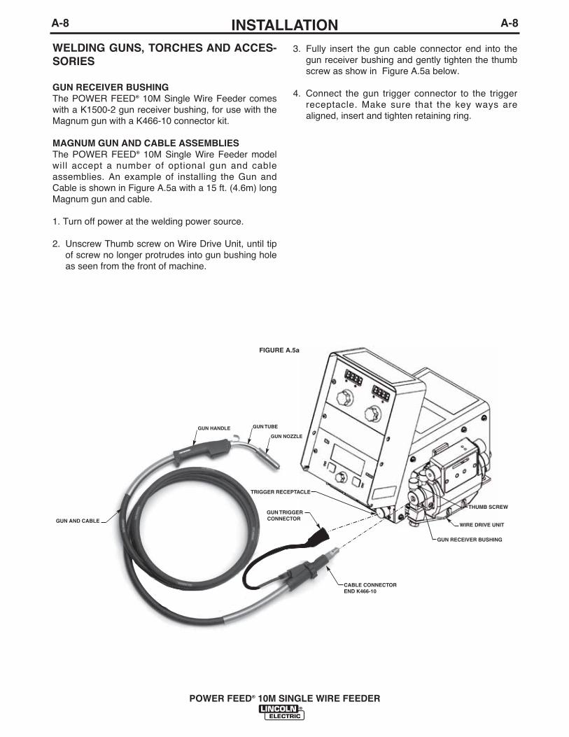
WELDING GUNS, TORCHES AND ACCES-SORIES
GUN RECEIVER BUSHINGThe POWER FEED® 10M Single Wire Feeder comeswith a K1500-2 gun receiver bushing, for use with theMagnum gun with a K466-10 connector kit.
MAGNUM GUN AND CABLE ASSEMBLIESThe POWER FEED® 10M Single Wire Feeder modelwill accept a number of optional gun and cableassemblies. An example of installing the Gun andCable is shown in Figure A.5a with a 15 ft. (4.6m) longMagnum gun and cable.
1. Turn off power at the welding power source.
2. Unscrew Thumb screw on Wire Drive Unit, until tipof screw no longer protrudes into gun bushing holeas seen from the front of machine.
3. Fully insert the gun cable connector end into thegun receiver bushing and gently tighten the thumbscrew as show in Figure A.5a below.
4. Connect the gun trigger connector to the triggerreceptacle. Make sure that the key ways arealigned, insert and tighten retaining ring.
WIRE DRIVE UNIT
THUMB SCREW
GUN RECEIVER BUSHING
TRIGGER RECEPTACLE
GUN TRIGGERCONNECTOR
CABLE CONNECTOR END K466-10
FIGURE A.5a
GUN NOZZLE
GUN HANDLE GUN TUBE
GUN AND CABLE

A-9INSTALLATION
POWER FEED® 10M SINGLE WIRE FEEDER
A-9
WIRE FEED SHUT DOWN CIRCUIT
The wire feed shut down circuit is used to stop thewire feed in the event of a fault. The most commonuse of the circuit is with water cooled guns. A flowsensor is connected to the circuit to protect the weld-ing gun if the water flow is interrupted.
The POWER FEED® 10M Single Wire Feeder has twoleads, 570A and 570B, located inside the wire drivethat are electrically common. If flow switch is used,separate these leads and connect to normally closedflow switch terminals when water is flowing. Connectthe flow sensor to these two leads.
CHANGING THE GEAR RATIO
The POWER FEED® 10M Single Wire Feeder wiredrive may be configured for either low speed or highspeed, depending upon the application. The wirefeeders are factory assembled for low speed opera-tion and include a gear for high speed operation.
FIGURE A.6
ITEM DESCRIPTION1 Gear.2 Screw holding feed plate to wire feeder.3 Low speed position, screw holding feed
plate to wire feeder.4 High speed position, screw holding feed
plate to wire feeder.
To change the gear ratio:
1. Turn off power at the welding power source.
2. Open the wire drive door.
3. Use a 3/16" Allen wrench to remove the screwsholding the feed plate to the wire feeder.
4. Use a Phillips screwdriver to remove the screw andwashers holding the gear to the shaft.
5. Remove the gear.
6. Lightly cover the shaft with engine oil or equivalent.Install the desired gear onto the shaft.
7. Reassemble the screw and washers securing thegear to the shaft.
8. Reassemble the screws in the appropriate positionfor holding the feed plate to the wire feeder.
GearRatio
Low Speed
High Speed
Speed
50-800 ipm(1.27-20.3 m/m)
75-1200 ipm(2.03-30.5 m/m)
.025-1/16in.(0.6 - 1.6 mm)
.025-.045 in.(0.6 - 1.2 mm)
.035 - 5/64 in.(0.9 - 2.0 mm)
.035 - .045 in.(0.9 - 1.2 mm)
Wire SizeSolid Core
Purp ose:
Best for mostGMAW and FCAWwelding. The lowspeed gear ratioprovides the mostforce for pushingwires through longguns or pull ingwire through con-duits.
Suitable only forsmall diameterwires operating athigh wire feedspeeds. Feedingforce is less.

WIRE REEL LOADING
Spindle PlacementThe wire reel stand provides two mounting locationsfor the spindle. Each mounting location consists of atube in the center of the mast and locating slots.
Loading 16 to 44 lb. (7.3 – 20kg) Spools
1. Squeeze the release bar on the retaining collar andremove it from the spindle.
2. Place the spool on the spindle, aligning the spindlebrake pin with one of the holes in the back side ofthe spool. An indicator mark on the end of the spin-dle shows the orientation of the brake holding pin.Be certain the wire feeds off of the spool in theproper direction.
3. Re-install the retaining collar. Make sure that therelease bar snaps out and that the retaining collarfully engages the groove on the spindle.
Loading 10 to 15 lb. (4.5 – 6.8kg) Spools
A K468 spindle adapter is required for loading 2" widespools on 2" (51mm) spindles. Use a K468 spindleadapter for loading 2-1/2" (64mm) wide spools.
1. Squeeze the release bar on the retaining collar andremove it from the spindle.
2. Place the spindle adapter on the spindle, aligningthe spindle brake pin with the hole in the adapter.
3. Place the spool on the spindle and align theadapter brake tab with one of the holes in the backside of the spool. An indicator mark on the end ofthe spindle shows the orientation of the brake tab.Be certain the wire feeds off of the spool in theproper direction.
4. Re-install the retaining collar. Make sure that therelease bar snaps out and that the retaining collarfully engages the groove on the spindle.
9. Loosen the two screws on the bottom of the feedplate clamping collar.
10. Rotate the feed plate to the desired position.
11. Tighten the two screws on the bottom of the feedplate clamping collar.
FIGURE A.7
12. Remove the rear access panel on the wire drive.
13. Locate DIP switches on the Wire Drive Board.
14. Set DIP switch #8 to the desired setting.
15. Reinstall the rear access panel to the wire drive.
16. Restore power.
LOW SPEED SCREW SETTING
HIGH SPEED SCREW SETTING
SCREW FOR ROTATING FEED PLATE
CLAMPING COLLAR SCREWS
DIP Switch #8 PositionONOFF
Gear RatioHigh speed
Low speed (default)
A-10INSTALLATION
POWER FEED® 10M SINGLE WIRE FEEDER
A-10

INSTALLATION
POWER FEED® 10M SINGLE WIRE FEEDER
A-11 A-11
Using K1504-1 Coil Reel50-60 lb. (22.7 - 27.2 kg) Coil Mounting(See Figure A.10)
1. Make sure the spindle of the wire reel stand is inthe upper position.
2. With the coil reel assembly mounted to a 2" (51mm)spindle, loosen the spinner nut and remove thecover plate. Alternatively, lay the coil reel assemblyflat on the floor and loosen the spinner nut andremove the cover plate.
3. Place the coil of electrode on the reel so it unwindsfrom the bottom as it rotates.
4. Tighten the spinner nut as much as possible byhand using the cover plate spokes for leverage.DO NOT hammer on the spinner nut.
5. Cut and remove only the tie wire holding the freeend of the coil. Hook the free end around the rim ofthe cover plate and secure it by wrapping it around.Cut and remove remaining tie wires.
• Always be sure the free end of the coil is secure-ly held while the tie wires are being cut and untilthe wire is feeding through the drive rolls.Failure to do this will result in "backlashing" ofthe coil, which may tangle the wire. A tangledcoil will not feed and must either be untangled ordiscarded.
------------------------------------------------------------------------
6. Be sure the coil is engaged with the spindle brakepin and the release bar on the retaining collar "popsup". The retaining collar must fully engage theretaining groove on the spindle.
CAUTION
SPINNER NUT
CARDBOARDLINER
COVERPLATE
TIEWIRE
SPRING ARM
REEL
COIL
SLOTS
FIGURE A.10

A-12INSTALLATION
POWER FEED® 10M SINGLE WIRE FEEDER
A-12
Loading 30 lb. (13.6 kg) Readi-Reels(See Figure A.11)
A K363-P Readi-Reel adapter is required for loadingthese spools on 2" (51mm) spindles.
1. Squeeze the release bar on the retaining collar andremove it from the spindle.
2. Place the Readi-Reel adapter on the spindle, align-ing the spindle brake pin with one of the holes inthe adapter.
3. Re-install the retaining collar. Make sure that therelease bar snaps out and that the retaining collarfully engages the groove on the spindle.
4. Rotate the spindle and adapter until the retainingspring is at the 12 oʼclock position.
5. Position the Readi-Reel so that electrode de-reelsin the proper direction.
6. Set one of the Readi-Reel inside cage wires on theslot in the retaining spring.
7. Lower the Readi-Reel to depress the retainingspring and align the other inside cage wires with thegrooves in the adapter.
8. Slide the cage all way onto the adapter until theretaining spring "pops up" fully.
Removing a Readi-Reel
1. To remove a Readi-Reel from the an adapter,depress the retaining spring with a thumb whilepulling the Readi-Reel cage from the adapter withboth hands. Do not remove the adapter from thespindle.
WELD WIRE ROUTINGThe electrode supply may be either from reels, Readi-Reels, spools, or bulk packaged drums or reels.Observe the following precautions:
a) The electrode must be routed to the wire driveunit so that the bends in the wire are at a mini-mum, and also that the force required to pull thewire from the reel into the wire drive unit is kept ata minimum.
b) The electrode is “hot” when the gun trigger ispressed and must be insulated from the boomand structure.
c) If more than one wire feed unit shares the sameboom and are not sharing the some power sourceoutput stud, their wire and reels must be insulatedfrom each other as well as insulated from theirmounting structure.
SPINDLE
BRAKE PIN
GROOVES
ADAPTER
RETAININGSPRING
READI- REEL
CAGE WIRE RELEASE
BAR
RETAINING COLLAR
FIGURE A.11

A-13INSTALLATION
POWER FEED® 10M SINGLE WIRE FEEDER
A-13
SHIELDING GAS CONNECTION
Maximum inlet pressure is 100 psi. (6.9 bar.)
Install the shielding gas supply as follows:
1. Secure the cylinder to prevent it from falling.
2. Remove the cylinder cap. Inspect the cylindervalves and regulator for damaged threads, dirt,dust, oil or grease. Remove dust and dirt with aclean cloth. DO NOT ATTACH THE REGULATORIF OIL, GREASE OR DAMAGE IS PRESENT!Inform your gas supplier of this condition. Oil orgrease in the presence of high pressure oxygen isexplosive.
3. Stand to one side away from the outlet and openthe cylinder valve for an instant. This blows awayany dust or dirt which may have accumulated in thevalve outlet.
4. Attach the flow regulator to the cylinder valve andtighten the union nut(s) securely with a wrench.Note: if connecting to 100% CO2 cylinder, insertregulator adapter between regulator and cylindervalve. If adapter is equipped with a plastic washer,be sure it is seated for connection to the CO2 cylin-der.
5. Attach one end of the inlet hose to the outlet fittingof the flow regulator. Attach the other end to thewelding system shielding gas inlet. Tighten theunion nuts with a wrench.
CYLINDER may explode if damaged.• Keep cylinder upright and chained to a
support.• Keep the cylinder away from all areas
where it may be damaged.• Never lift the welder with cylinder attached.• Never allow the welding electrode to touch cylinder.• Keep the cylinder away from welding or other live
electrical circuits.BUILDUP OF SHIELDING GAS mayharm health or kill.• Shut off the shielding gas supply when
it is not in use.
SEE AMERICAN NATIONAL STANDARD Z-49.1,“SAFETY IN WELDING AND CUTTING” PUBLISHEDBY THE AMERICAN WELDING SOCIETY.------------------------------------------------------------------------
WARNING6. Before opening the cylinder valve, turn the regulator
adjusting knob counterclockwise until the adjustingspring pressure is released.
7. Standing to one side, open the cylinder valve slowlya fraction of a turn. When the cylinder pressuregage stops moving, open the valve fully.
8. The flow regulator is adjustable. Adjust it to the flowrate recommended for the procedure and processbeing used before making a weld.

A-14INSTALLATION
POWER FEED® 10M SINGLE WIRE FEEDER
A-14
Hard Automation System
Shown with• K2657-1 Control Box• K1780-2 PF-10/R • K2203-1 Power Wave® 455M/STT• K2205-1 Wire Drive Module
Multiple Wire Feeder System• Load one feeder with solid wire, the other with flux
cored.• Great for pipeline work.
Shown with• K2429-1 ArcLink T Cable Connector• K2536-1• K2536-1 Power Feed® 25M• K2203-1 Power Wave® 455M/STT
ArcLink Systems
Many other ArcLink systems may be assembledbesides those shown in this manual. The majority willself configure. If an assembled system flashes the sta-tus light green rapidly on all components, contact theLincoln Electric Company for further assistance.
Current Power Feed® 10M models that will not selfconfigure...
• K2316-1 Power Feed 10M Dual Boom
These configurations will require Dip Switches to beset. See the power source instruction manual on howto disable self configuration.
EXAMPLES OF CONNECTING ANARCLINK POWER WAVE SYSTEM
ArcLink Power Wave® products may be configured inmany different ways. The flexible system allows multi-ple wire feeders to be connected to the same powersource. The diagrams represent some of the commonmethods for connecting ArcLink Products.
Important: Bench model wire feeders cannot be sepa-rated into a separate control box and wire drive for aboom system.
Common ArcLink SystemsThe following Power Wave® systems may all beassembled without any changes to the equipment DIPswitches
Basic Semi-Automatic System• Great for general fabrication.
Shown with• K2230-2 POWER FEED® 10M Single Wire Feeder • K2203-1 Power Wave® 455M/STT
Robotic/Semi-Automatic System• Use the bench feeder for offline welding.
Shown with• K2230-2 POWER FEED® 10M Single Wire Feeder• K1780-2 PF-10/R • K2203-1 Power Wave® 455M/STT• K2205-1 Wire Drive Module
B-1OPERATIONB-1
POWER FEED® 10M SINGLE WIRE FEEDER
WIRE FEEDER
POSITIVE OUTPUT
NEGATIVE OUTPUT
PROTECTIVEGROUND
WARNING ORCAUTION
SAFETY PRECAUTIONS
Read this entire section of operating instructionsbefore operating the machine.
ELECTRIC SHOCK can kill.
• Do not touch electrically live partsor electrodes with your skin or wetclothing.
• Insulate yourself from the work andground.
• Always wear dry insulating gloves.• Do not use AC welder if your cloth-
ing, gloves or work area is damp orif working on, under or inside work-piece.Use the following equipment:-DC manual (stick) welder.-AC welder with reduced voltagecontrol.
• Do not operate with panelsremoved.
• Disconnect input power before servicing.-----------------------------------------------------------------------READ THIS WARNING, PROTECT YOURSELF &OTHERS.
FUMES AND GASES can bedangerous.• Keep your head out of fumes.
• Use ventilation or exhaust at the arc,or both,to keep fumes and gases fromyour breathing zone and general area.
WELDING SPARKS can cause fireor explosion.• Do not weld near flammable material.
• Do not weld on containers which haveheld flammable material.
ARC RAYS can burn.• Wear eye, ear, and body protection.
ONLY QUALIFIED PERSONS SHOULD INSTALL,USE OR SERVICE THIS EQUIPMENT. READ ANDFOLLOW THE MANUFACTURER’S INSTRUC-TIONS, EMPLOYER’S SAFETY PRACTICES ANDMATERIAL SAFETY DATA SHEETS (MSDS) FORCONSUMABLES.
-------------------------------------------------------------
WARNING
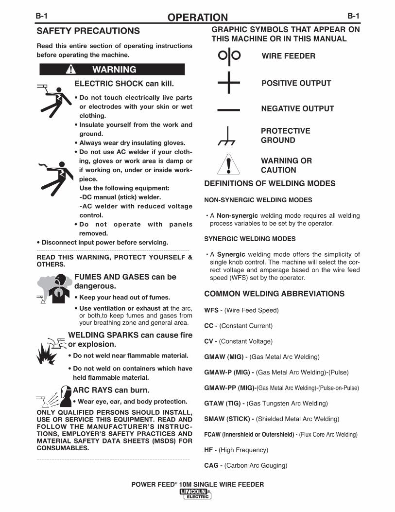
GRAPHIC SYMBOLS THAT APPEAR ONTHIS MACHINE OR IN THIS MANUAL
DEFINITIONS OF WELDING MODES
NON-SYNERGIC WELDING MODES
• A Non-synergic welding mode requires all weldingprocess variables to be set by the operator.
SYNERGIC WELDING MODES
• A Synergic welding mode offers the simplicity ofsingle knob control. The machine will select the cor-rect voltage and amperage based on the wire feedspeed (WFS) set by the operator.
COMMON WELDING ABBREVIATIONS
WFS - (Wire Feed Speed)
CC - (Constant Current)
CV - (Constant Voltage)
GMAW (MIG) - (Gas Metal Arc Welding)
GMAW-P (MIG) - (Gas Metal Arc Welding)-(Pulse)
GMAW-PP (MIG)-(Gas Metal Arc Welding)-(Pulse-on-Pulse)
GTAW (TIG) - (Gas Tungsten Arc Welding)
SMAW (STICK) - (Shielded Metal Arc Welding)
FCAW (Innershield or Outershield) - (Flux Core Arc Welding)
HF - (High Frequency)
CAG - (Carbon Arc Gouging)

B-2OPERATIONB-2
POWER FEED® 10M SINGLE WIRE FEEDER
PROCESS LIMITATIONS
The POWER FEED® 10M Single Wire Feeder is notsuitable for:• SAW• GTAW with HF
Not all weld modes or processes described in this manual are avail-able on all Power Wave® power sources.
REQUIRED EQUIPMENT
Lincolnʼs POWER FEED® 10M Single Wire Feeder isdesigned for use with the Power Wave family of powersources. These include:
• Power Wave® 355 • Power Wave® 455M CE• Power Wave® 455 • Power Wave® 455M STT• Power Wave® 455/STT • Power Wave® 455M STT CE• Power Wave® 455M • Power Wave® 655
ADDITIONAL REQUIRED EQUIPMENT
• Drive Roll Kits• Control Cables• Gun and Cable Assembly• Weld Wire• Shielding gas• Work Cable and Clamp
EQUIPMENT LIMITATIONS
• The POWER FEED® 10M Single Wire Feeder doesnot operate with the Power Wave® 450.
• The POWER FEED® 10M Single Wire Feeder doesnot operate with any analog based power sources(CV-xxx machines, DC-xxx machines, etc.)
• The Memory Panel is required to set procedure limits.• The Boom model does not support push-pull guns
or GTAW welding.• A push-pull gun and foot amptrol may not be
plugged into the POWER FEED® 10M Single WireFeeder at the same time.
• Spool guns do not operate with the Power Feed®
10M.
PRODUCT DESCRIPTION
General Physical Description
The POWER FEED® 10M Single Wire Feeder is amodular wire feeder, consisting of two components - awire drive and a control box - are available assem-bled as a bench unit or as a boom system. Highspeed, highly reliable digital cables connect the com-ponents together and to the Power Wave powersource.
The POWER FEED® 10M Single Wire Feeder systemhas the ability to connect multiple wire feeders to onepower source, use the same power source to weld intwo different locations (not simultaneously), or load adifferent electrode on each feeder to eliminate changeover time.
The powerful four roll wire drive system sets theindustry standard for ease of use. Its patented designallows for tool-less change out of wire guides anddrive rolls greatly reducing set up time.
General Functional Description
• The POWER FEED® 10M Single Wire Feeder is ahighly versatile wire feeder with easy to use fea-tures that make it easy for the operator to adjust thearc for specific preferences.
• The new MSP4 panel clearly displays key weldinginformation. Use the MSP4 panel to quickly adjustweld settings, arc starting parameters, arc end para-meters and set-up variables.
(For Codes 11377 and below)• The POWER FEED® 10M Single Wire Feeder wire
feeder is provided with an infrared red (IR) port.Transferring welding settings from one wire feederto another is accomplished with a common palmcomputer.
• When the POWER FEED® 10M Single Wire Feederis coupled to a Power Wave welding power source,the result is a welding system with absolutely supe-rior arc performance.
RECOMMENDED PROCESSESThe POWER FEED® 10M Single Wire Feeder is wellsuited for all MIG welding processes, giving premiumarc performance especially with unusual alloys andout of position work.
• GMAW • SMAW• GMAW-Pulse • GTAW (Touch Start TIG only)• GMAW-STT • CAG• FCAW

B-3OPERATIONB-3
POWER FEED® 10M SINGLE WIRE FEEDER
BENCH MODEL FEATURES
Pulse Welding or STT Welding:
CV Welding:
BASIC POWER FEED® 10M Single Wire Feeder WELDING SYSTEM CONFIGURATION

B-4OPERATIONB-4
ITEM DESCRIPTION
1 Status LED indicates system status.
2 Digital Meter Display is a bright LED display of key welding information. Adjusting ParameterKnobs.
3 MSP4 Panel is used to set the weld mode, adjust the arc, change arc start/end parametersand for set-up information.
4 Cold Feed - Gas Purge Switch, press the switch up to feed wire with weld output off. Press theswitch down for gas flow with weld output off.
5 2 step - 4 step Switch is used to choose between a 2 step trigger or a 4 step trigger operation.
6 Location for Optional Memory Panel. (Order K2360-1 for the memory panel. See AccessoriesSection).
7 Cover for Optional Water Cooling Kit, remove when the water cooling kit is installed. Seeinstructions with water cooling Kit.
8 Trigger Connector 5-pin amphenol for connecting the MIG gun trigger. See Installation Sectionfor detail.
POWER FEED® 10M SINGLE WIRE FEEDER
2
6
3
5 1 4 7 8
FRONT PANEL CONTROLS AND CONNECTIONS
CASE FRONT CONTROLS
FIGURE B.1

B-5OPERATIONB-5
1. STATUS LEDThe status LED indicates system status. Normaloperation is a steady green light.
Note: During normal power-up, the LED may flashred and/or green as the equipment performs self tests.
LED condition Definition
Steady green System okay. The power source andwire feeder are communicating nor-mally.
Blinking green Occurs during a reset and indicatesthe power source is identifying eachcomponent in the system. This is nor-mal for the first 10 seconds afterpower-up, or if the system configura-tion is changed during operation.
Alternating Non-recoverable system fault. If thegreen and red power source or wire feeder status
LED is flashing any combination ofred and green, errors are present inthe system. Read the error codebefore the machine is turned off.
Instructions for reading the error codeare detailed in the Service Manual.Individual code digits are flashed inred with a long pause between digits.If more than one code is present, thecodes will be separated by a greenlight.
To clear the error, turn the powersource OFF, and then back ON toreset. See troubleshooting section.
Steady red Non recoverable hardware fault.Generally indicates a problem withthe cables connecting the wire feederto the power source.
Blinking red Not applicable.
2. DIGITAL METERS AND OUTPUTENCODER KNOBS (See Figure B.2)
The primary weld procedure settings are controlledand displayed using digital meters and output encoderknobs located at the top of the POWER FEED® 10MSingle Wire Feeder control panel.
POWER FEED® 10M SINGLE WIRE FEEDER
FIGURE B.2A. WIRE FEED SPEED/AMMETER DISPLAY
This meter displays either the wire feed speed or cur-rent value (Amps) depending upon welding process(Mode) being used and the status of the wire feederand power source. Written below the display is "WFS"and "Amps". An LED light illuminates which value isbeing displayed on the meter. The knob below themeter adjusts the value displayed on the meters.
Prior to Welding DescriptionCV Welding Processes Meter displays the preset
WFS value.CC Welding Processes Meter displays the preset
Amps.During Welding
An Weld Processes Meter displays displays theactual average weldingAmps.
After WeldingAn Weld Processes The meter holds the actual
current value for 5 sec-onds. The display blinks toindicate the POWERFEED® 10M Single WireFeeder is in the "Hold"period. If the output isadjusted while in the"Hold" period, the POWERFEED® 10M Single WireFeeder will revert to the"Prior to welding" displaydescribed above.
Note: If the output knob for the WFS/AMPS is adjust-ed while the POWER FEED® 10M Single Wire Feederis in the “Hold” period, the POWER FEED® 10M SingleWire Feeder will immediately revert to the “Prior toWelding” display.
The default wire feed speed units are inches/minute andcan be changed to meters/minute by entering the "Set-upMenu" in this Operation Section. The wire feed speed iscalibrated to within ±2%. Refer to the power source man-
400 263WFS AMPS VOLTS TRIM
A B

AFTER WELDINGWeld Process Volt/Trim Display
All Processes After welding, the meter holds the actualaverage arc voltage for 5 seconds.During this time, the display flashes toindicate the wire feeder is in the "Hold"period. Output adjustment while in the"Hold" period results in the "prior to oper-ation" characteristics described above.
B. VOLTS / TRIM DISPLAY
The voltage/trim meter displays either the voltage ortrim value, depending upon the welding process(mode) being used and the status of the wire feederand power source.
PRIOR TO WELDINGWeld Process Volts / Trim Display prior to operation
Nonsynergic CV Displays the preset Voltage value.
Synergic CV Displays the preset Voltage value.
Synergic Displays the preset Trim value from 0.50CV-Pulse to 1.50, with 1.00 as the default. Trim
adjusts the arc length for Pulse programs.Lower the trim value to decrease the arclength, and raise the trim value toincrease the arc length. A trim value of1.00 is optimum for most conditions.
Synergic CV-STT • Adjusts the background current of theSTT waveform. Used to modify the heatinput.
• Linc Net Power Sources: Displays thebackground current as a value from 0.50to 1.50, with 1.00 as the default. Lowerthe trim value to decrease the heat input,and raise the trim value to increase theheat input. A trim value of 1.00 is opti-mum for most conditions.
• Arc Link Power Sources: Displays thebackground current in amps. Lower thebackground current to decrease the heatinput and raise the background currentto increase the heat input.
Nonsynergic Displays the preset CP value from 0 to 20.Power The Power mode is best for thin sheet
metal and aluminum applications.
DURING WELDINGWeld Process Volts / Trim Display
All Processes Displays ActualAverage Arc Voltage
B-6OPERATIONB-6
POWER FEED® 10M SINGLE WIRE FEEDER
SYNERGIC CV VOLTAGE DISPLAY
Synergic CV programs feature an ideal voltage bestsuited for most procedures. Use this voltage as astarting point for the weld procedure and adjust ifneeded for personal preferences.
The voltage is calibrated to ±2% over a range of 10 to45 volts.
When the voltage knob is rotated, the display willshow an upper or lower bar indicating if the voltage isabove or below the ideal voltage.
• Preset voltage above idealvoltage. (upper bar displayed)
• Preset voltage at idealvoltage. (no bar displayed)
• Preset voltage below idealvoltage. (lower bar displayed)
• Limit setting for restricting the operators range ofcontrol.
• Lockout to prevent unauthorized changes tomachine configuration.
(For Codes 11377 and below)Additionally, the MSP4 includes an infrared (IR) portfor wireless communication and configuration using aPalm OS based hand held computer and a simplifiedcontrol layout.
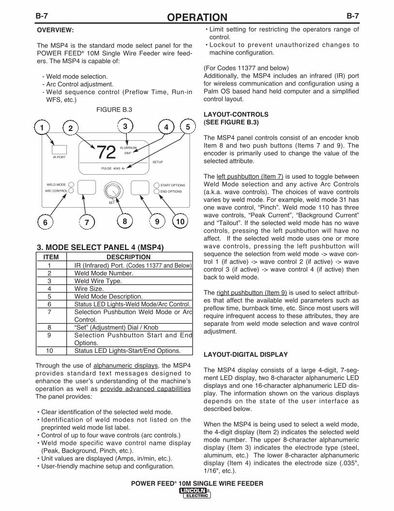
LAYOUT-CONTROLS(SEE FIGURE B.3)
The MSP4 panel controls consist of an encoder knobItem 8 and two push buttons (Items 7 and 9). Theencoder is primarily used to change the value of theselected attribute.
The left pushbutton (Item 7) is used to toggle betweenWeld Mode selection and any active Arc Controls(a.k.a. wave controls). The choices of wave controlsvaries by weld mode. For example, weld mode 31 hasone wave control, “Pinch”. Weld mode 110 has threewave controls, “Peak Current”, “Background Current”and “Tailout”. If the selected weld mode has no wavecontrols, pressing the left pushbutton will have noaffect. If the selected weld mode uses one or morewave controls, pressing the left pushbutton willsequence the selection from weld mode -> wave con-trol 1 (if active) -> wave control 2 (if active) -> wavecontrol 3 (if active) -> wave control 4 (if active) thenback to weld mode.
The right pushbutton (Item 9) is used to select attribut-es that affect the available weld parameters such aspreflow time, burnback time, etc. Since most users willrequire infrequent access to these attributes, they areseparate from weld mode selection and wave controladjustment.
LAYOUT-DIGITAL DISPLAY
The MSP4 display consists of a large 4-digit, 7-seg-ment LED display, two 8-character alphanumeric LEDdisplays and one 16-character alphanumeric LED dis-play. The information shown on the various displaysdepends on the state of the user interface asdescribed below.
When the MSP4 is being used to select a weld mode,the 4-digit display (Item 2) indicates the selected weldmode number. The upper 8-character alphanumericdisplay (Item 3) indicates the electrode type (steel,aluminum, etc.) The lower 8-character alphanumericdisplay (Item 4) indicates the electrode size (.035",1/16", etc.).
B-7OPERATIONB-7
POWER FEED® 10M SINGLE WIRE FEEDER
OVERVIEW:
The MSP4 is the standard mode select panel for thePOWER FEED® 10M Single Wire Feeder wire feed-ers. The MSP4 is capable of:
- Weld mode selection.- Arc Control adjustment.- Weld sequence control (Preflow Time, Run-in
WFS, etc.)
3. MODE SELECT PANEL 4 (MSP4)ITEM DESCRIPTION
1 IR (Infrared) Port. (Codes 11377 and Below)2 Weld Mode Number.3 Weld Wire Type.4 Wire Size.5 Weld Mode Description.6 Status LED Lights-Weld Mode/Arc Control.7 Selection Pushbutton Weld Mode or Arc
Control.8 “Set” (Adjustment) Dial / Knob9 Selection Pushbutton Start and End
Options.10 Status LED Lights-Start/End Options.
START OPTIONS
END OPTIONS
SET
SETUP
IR PORT
PULSE 4043 Ar
3/64"
ALUMINUM72
WELD MODE
ARC CONTROL
21 3 4 5
6 107 8 9
Through the use of alphanumeric displays, the MSP4provides standard text messages designed toenhance the userʼs understanding of the machineʼsoperation as well as provide advanced capabilitiesThe panel provides:
• Clear identification of the selected weld mode.• Identification of weld modes not listed on the
preprinted weld mode list label.• Control of up to four wave controls (arc controls.)• Weld mode specific wave control name display
(Peak, Background, Pinch, etc.).• Unit values are displayed (Amps, in/min, etc.).• User-friendly machine setup and configuration.
FIGURE B.3

CHANGING ARC WAVE CONTROL
If the selected weld mode uses any of the four availablewave controls, users can press the left MSP4 pushbuttonuntil the ARC CONTROL LED is illuminated. The value,name and units (if applicable) of the available wave con-trols will appear. Note that the name of the control isderived from the weld table and may not necessarilyappear as "Wave Control". Repeated pressing of the leftMSP4 pushbutton will cycle through all active wave con-trols and then the weld mode. Turning the MSP4 encoderwill change the value of the displayed wave control.
CHANGING WELD SEQUENCE BEHAVIOR
Weld sequencing attributes are grouped into two cate-gories, START OPTIONS and END OPTIONS. STARTOPTIONS may include Preflow Time, Run-in Wire FeedSpeed, and Start Time. END OPTIONS may includeSpot Timer, Crater Time, Burnback Time and PostflowTime. The attributes that appear in the START and ENDOPTIONS are weld mode dependent. For example, if aTIG weld mode is selected, Run-in WFS will not appearsince it is not relevant to the selected process. Repeatedpressing of the right MSP4 pushbutton will cycle throughall relevant START and END OPTIONS. Turning theMSP4 encoder will change the value of the selectedoption.
When the Start Time attribute is set to a value other thanOFF, the START OPTIONS LED will blink synchronouswith the WFS and VOLTS/TRIM LEDʼs on the dual-dis-play panel. This blinking is used to indicate that start wirefeed speed and voltage/trim can now be set to values dif-ferent from those used while welding. Similarly, if theCrater Time attribute is set to a value other than OFF,the END OPTIONS LED will blink synchronously with thedual-display LEDʼs, indicating that crater wire feed speedand voltage/trim now can be set to values different fromthose used while welding.
INFRARED (IR) CONTROL(For Codes 11377 and below)The MSP4 interface includes an infrared transceiver.This allows wireless machine configuration using a PalmOS based hand held computer. A proprietary Palm OSapplication, Weld Manager, was developed for this pur-pose. (Contact Lincoln Electric for more information onthis feature.)
LOCKOUT/SECURITY
The MSP4 can be optionally configured to prevent thewelder from changing selected user interface controls.By default, all user interface controls can be changed.Weld Manager software (for Palm OS or PC) must beused to lock or unlock user interface controls and to set apass code.
B-8OPERATIONB-8
The 16-character alphanumeric display (Item 5) indi-cates the process type and other information, theexact content of which depends on the selected weldmode. This additional information may include specificelectrode type (e.g. 4043) and/or a description of therecommended gas (e.g. HeArCO2).
When the MSP4 is being used to change the value ofan attribute, the 7-segment displays show the select-ed attributeʼs value. The upper 8-character alphanu-meric display is typically not used while changing anattributeʼs value. The lower 8-character alphanumericdisplay is used to indicate the units of the selectedattribute (e.g. seconds, in/min, etc.). The 16-characteralphanumeric display is used to display the name ofthe selected attribute.
The content of the displays while the user interface isbeing used for advance machine configuration (e.g.limit setting, pass code entering, machine setup, etc.)is described in later sections.
POWER-UP SEQUENCE
When power is first applied to the machine, a lamptest is performed. All discrete LEDʼs are turned on, all7-segment displays will show a pattern of "8." and allalphanumeric displays will show a hatch patternwhere every-other pixel is illuminated. The lamp testwill last for two seconds, after which all displays areturned back off. The 16-character alphanumeric dis-play will show "Initializing…" while waiting for the WeldSequencer to announce bus available. The MSP4alphanumeric displays will then display the name ofthe weld table loaded in the power source while theuser interface prepares the machine for operation.After all initialization is complete, the MSP4 will dis-play the weld mode information for the mode numberthat was selected when the machine was last pow-ered down.
CHANGING WELD MODES
To select a weld mode, press the left MSP4 pushbut-ton until the WELD MODE LED is illuminated. Turnthe MSP4 encoder until the desired weld mode num-ber is displayed. As the MSP4 encoder knob is rotat-ed, only the weld mode number is displayed. After 1second of encoder idle time, the user interface willchange to the selected weld mode and the newmodeʼs electrode type, electrode size and processinformation will appear.
POWER FEED® 10M SINGLE WIRE FEEDER

B-9OPERATIONB-9
POWER FEED® 10M SINGLE WIRE FEEDER
LIMIT SETTING
The MSP4 can be optionally configured to limit the opera-torʼs range of control of any weld parameter (weld WFS, arccontrol, etc.). Limits are only available with the DualProcedure/Memory Panel.
MACHINE SETUP/USER PREFERENCES
The MSP4 can be used to configure and troubleshoot themachine.
ACCESSING THE MACHINE SETUP MENU
To access the Machine Setup menu, press both MSP4 pushbuttons simultaneously. The MSP4 7-segment display willdisplay the first user preference, "P.0", and the SETUP LEDwill illuminate.
• Pressing the left MSP4 pushbutton will exit the entireMachine Setup menu while in the P.0 user preference.
• Turning the MSP4 encoder knob will select other availableUser Preferences.
• To exit the User Preference Menu, either rotate the MSP4encoder until P.0 is displayed and press the left MSP4pushbutton or press both MSP4 push buttons simultane-ously at any time.

B-10OPERATIONB-10
POWER FEED® 10M SINGLE WIRE FEEDER
SET-UP FEATURES MENU(See Figure B.3a)
1. To access the set-up menu, press the Right andLeft buttons of the MSP4 panel simultaneously.Note that the set-up menu cannot be accessed ifthe system is welding, or if there is a fault (The sta-tus LED is not solid green).
Change the value of the blinking parameter by rotat-ing the SET knob.
2. After changing a parameter it is necessary to pressthe Right hand button to save the new setting.Pressing the Left button will cancel the change.
3. To exit the set-up menu at any time, press theRight and Left buttons of the MSP4 panel simulta-neously. Alternately, 1 minute of inactivity will alsoexit the set-up menu.
The Setup Menu gives access to the Setup Configuration. Stored in the setup configuration are user parametersthat generally only need to be set at installation. The parameters are grouped as shown in the following table.
SETUP MENU FEATURES
PARAMETERP.1 through P.99
P.100 through P.107
DEFINITIONUnsecured Parameters (always adjustable)Diagnostic Parameters (always read only)
2
6
3
5 1 4 7 8
LEDIndicator
Mode SelectPanel (MSP4)
Rightbutton
SET Knob
Leftbutton
FIGURE B.3a - SETUP MENU

B-11OPERATION
POWER FEED® 10M SINGLE WIRE FEEDER
B-11
USER DEFINED PARAMETERS
Parameter DefinitionExit Setup Menu
P.0 This setup menu parameter can be used to exit the setup menu. When P.0 is displayed, pressthe left Mode Select button to exit the setup menu.
P.1 Wire Feed Speed UnitsThis option selects which units to use for displaying wire feed speed.English = inches/minute wire feed speed units (default).Metric = meters/minute wire feed speed units.
P.2 Arc Display ModeThis option selects what value will be shown on the upper left display while welding.Amps = The left display shows Amperage while welding (default).WFS = The left display shows Wire Feed Speed while welding.
P.3 Display OptionsThis setup parameter was previously named "Display Energy"
If the previous software revision had this parameter set to display energy, that selection willremain.
This option selects the information displayed on the alphanumeric displayes while welding. Notall P.3 selections will be available on all machines. In order for each selection to be included inthe list, the power source must support that feature. A software update of the power source maybe needed to include the features.
Standard Display = The lower displays will continue to show preset information during and aftera weld (default).Show Energy = Energy is displayed, along with time in HH:MM:SS format.Show Weld Score = The accumulative weld score result is shown.
P.4 Recall Memory with TriggerThis option allows a memory to be recalled by quickly pulling and releasing the gun trigger. Torecall a memory, quickly pull and release the trigger the number of times that correspond to thememory number. For example, to recall memory 3, quickly pull and release the trigger 3 times.To recall memory 1, quickly pull and release the trigger the number of user memories plus 1.Memories cannot be recalled while the system is welding.Disabled = The gun trigger cannot be used to recall user memories (default).Enabled = The gun trigger can be used to recall user memories.

B-12OPERATIONB-12
POWER FEED® 10M SINGLE WIRE FEEDER
USER DEFINED PARAMETERS
Parameter Definition
P.5 Procedure Change MethodThis option selects how remote procedure selection (A/B) will be made. The selected procedurecan be changed locally at the user interface by pressing the 'A-Gun-B' button. The followingmethods can be used to remotely change the selected procedure:* Use an external switch wired to the procedure select input.* Quickly releasing and re-pulling the gun trigger.* Using a dual-schedule gun which incorporates a procedure select switch in the trigger mecha-
nism (pulling the trigger more than half way changes the procedure from A to B)
The possible values for this parameter are:* External Switch = Procedure selection may only be performed at the memory panel or an
external switch (e.g. K683).* Quick Trigger = The selected procedure can be changed remotely by releasing and re-pulling
the trigger quickly while welding. This feature is disabled in 4-Step trigger mode. The externalprocedure switch is disabled. To operate:- Select "GUN" on the memory panel.- Start the weld by pulling the gun trigger. The system will weld with procedure A settings.- While welding, quickly release then pull the gun trigger once. The system will switch to pro-
cedure B settings. Repeat to switch back to procedure A settings. The procedure can bechanged as many times as needed during the weld.
- Release the trigger to stop welding. The system will automatically return to procedure Asettings.
* Integral TrigProc = When using a Magnum DS dual-schedule gun (or similar) that incorpo-rates a procedure switch in the gun trigger mechanism. While welding in 2-step, machineoperation is identical to the "External Switch" selection. When welding in 4-step, additionallogic prevents procedure A from being re-selected when the trigger is released at step 2 of the4-step weld sequence. The machine will always operate in 2-step if a weld is made exclusive-ly in procedure A, regardless of the 2/4 step switch position (this is intended to simplify tackwelding when using a dual-schedule gun in 4-step).
P.6 Stall Factor AdjustmentThis option allows the adjustment of the stall factor in Push/Pull operation. The stall factor con-trols the stall torque of the push motor when using a push-pull gun. The wire feeder is factory-set to not stall unless there is a large resistance to feeding wire. The stall factor can be reducedto stall more easily and possibly prevent bird nesting. However, low stall factors can causemotor stalling during normal welding conditions, which results in the wire burning back to the tipor rapid tack welds. If you are experiencing bird nests, check for other feeding problems beforeadjusting the stall factor. The default value for the stall factor is 75, with a range of 5 to 100.
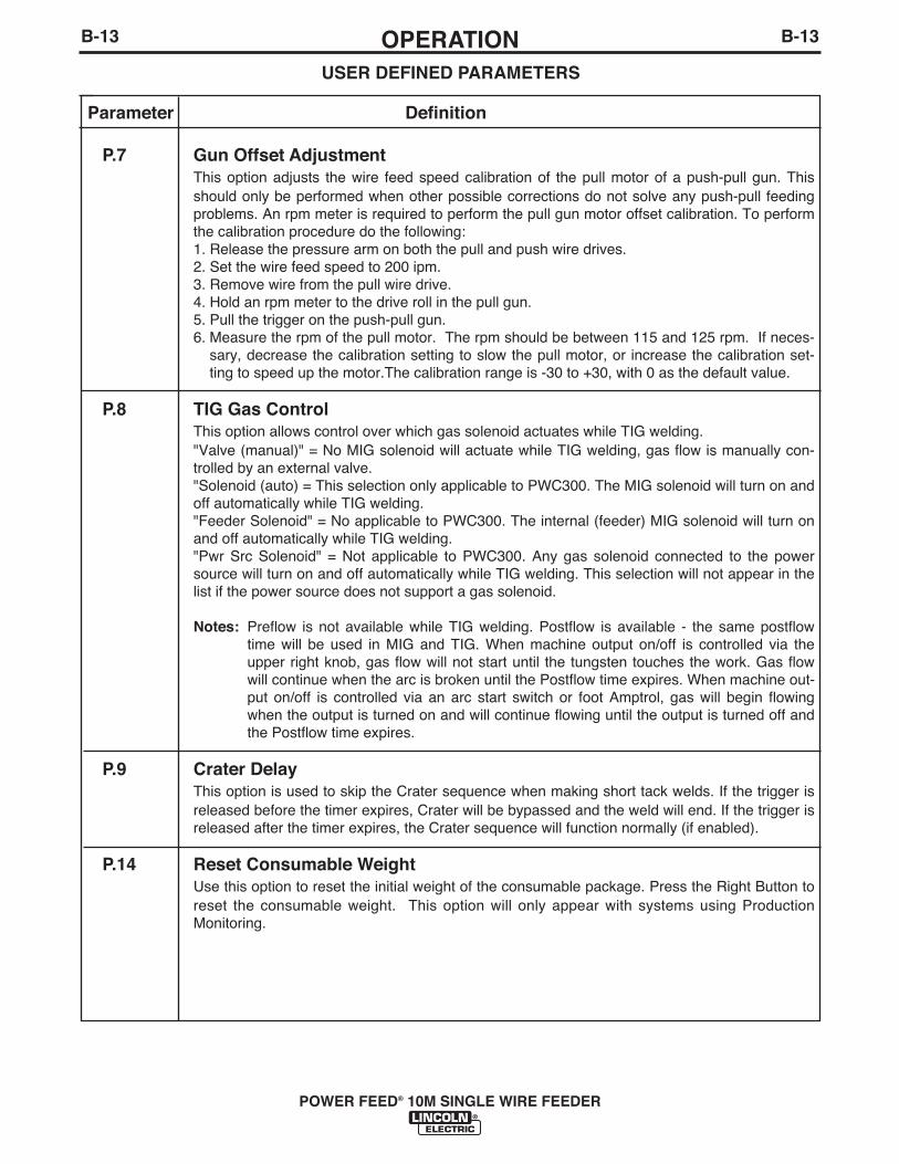
B-13OPERATIONB-13
POWER FEED® 10M SINGLE WIRE FEEDER
USER DEFINED PARAMETERS
Parameter Definition
P.7 Gun Offset AdjustmentThis option adjusts the wire feed speed calibration of the pull motor of a push-pull gun. Thisshould only be performed when other possible corrections do not solve any push-pull feedingproblems. An rpm meter is required to perform the pull gun motor offset calibration. To performthe calibration procedure do the following:1. Release the pressure arm on both the pull and push wire drives.2. Set the wire feed speed to 200 ipm.3. Remove wire from the pull wire drive.4. Hold an rpm meter to the drive roll in the pull gun.5. Pull the trigger on the push-pull gun.6. Measure the rpm of the pull motor. The rpm should be between 115 and 125 rpm. If neces-
sary, decrease the calibration setting to slow the pull motor, or increase the calibration set-ting to speed up the motor.The calibration range is -30 to +30, with 0 as the default value.
P.8 TIG Gas ControlThis option allows control over which gas solenoid actuates while TIG welding."Valve (manual)" = No MIG solenoid will actuate while TIG welding, gas flow is manually con-trolled by an external valve."Solenoid (auto) = This selection only applicable to PWC300. The MIG solenoid will turn on andoff automatically while TIG welding."Feeder Solenoid" = No applicable to PWC300. The internal (feeder) MIG solenoid will turn onand off automatically while TIG welding."Pwr Src Solenoid" = Not applicable to PWC300. Any gas solenoid connected to the powersource will turn on and off automatically while TIG welding. This selection will not appear in thelist if the power source does not support a gas solenoid.
Notes: Preflow is not available while TIG welding. Postflow is available - the same postflowtime will be used in MIG and TIG. When machine output on/off is controlled via theupper right knob, gas flow will not start until the tungsten touches the work. Gas flowwill continue when the arc is broken until the Postflow time expires. When machine out-put on/off is controlled via an arc start switch or foot Amptrol, gas will begin flowingwhen the output is turned on and will continue flowing until the output is turned off andthe Postflow time expires.
P.9 Crater DelayThis option is used to skip the Crater sequence when making short tack welds. If the trigger isreleased before the timer expires, Crater will be bypassed and the weld will end. If the trigger isreleased after the timer expires, the Crater sequence will function normally (if enabled).
P.14 Reset Consumable WeightUse this option to reset the initial weight of the consumable package. Press the Right Button toreset the consumable weight. This option will only appear with systems using ProductionMonitoring.

B-14OPERATIONB-14
POWER FEED® 10M SINGLE WIRE FEEDER
Parameter DefinitionP.16 Push-Pull Gun Knob Behavior
This option determines how the potentiometer on the Push/Pull torch will behave.Gun Pot Enabled = The welding wire feed speed is always controlled by the potentiometer on the push-pull gun (default). The left front panel knob is only used to adjust Start and Crater wire feed speed.Gun Pot Disabled = The wire feed speed is always controlled by the left front panel knob. This setting isuseful when the operator wishes to have wire feed speed settings recalled from memories and not havethe potentiometer "overwrite" the setting.Gun Pot Proc A = When in procedure A, the welding wire feed speed is controlled by the potentiometer onthe push-pull gun. When in procedure B, the welding wire feed speed is controlled by the left front panelknob. This setting allows a fixed wire feed speed to be selected in procedure changes.
P.20 Display Trim as Volts OptionThis option determines how trim is displayed.False = The trim is displayed in the format defined in the weld set (default).True = All trim values are displayed as a voltage.
P.22 Arc Start/Loss Error TimeThis option can be used to optionally shut off output if an arc is not established, or is lost for a specifiedamount of time. Error 269 will be displayed if the machine times out. If the value is set to OFF, machineoutput will not be turned off if an arc is not established nor will output be turned off if an arc is lost. Thetrigger can be used to hot feed the wire (default). If a value is set, the machine output will shut off if an arcis not established within the specified amount of time after the trigger is pulled or if the trigger remainspulled after an arc is lost. This is disabled while welding in Stick, TIG or Gouge. To prevent nuisanceerrors, set Arc Start/Loss Error Time to an appropriate value after considering all welding parameters (run-in wire feed speed, weld wire feed speed, electrical stick out, etc). To prevent subsequent changes to ArcStart/Loss Error Time, the setup menu should be locked out by setting Preference Lock = Yes using thePower Wave Manager software.
P.80 Sense From StudsUse this option for diagnostic purposes only. When power is cycled, this option is automatically reset toFalse. False = Voltage sensing is automatically determined by the selected weld mode and other machine set-tings (default). True = Voltage sensing is forced to "studs".
P.81 Sense Leads SelectionUsed in place of DIP switches for configuration of the work and electrode sense leads. This option willonly appear in the list if the power source has a hardware selection option. 67 pos polarity = An electrode sense lead is connected using positive polarity. This is used by mostGMAW welding procedures. 67 neg polarity = An electrode sense lead is connected using negative polarity. This is used by mostGTAW welding procedures and some Innershield procedures. 67 & 21 = An electrode sense lead and work sense lead are connected. Hardware Config = The hardware determines the best remote sensing configuration. This is applicable toMIG welding procedures only.
P.82 Voltage Sense DisplayAllows viewing of Voltage Sense Lead Selection to aid in troubleshooting. The configuration is displayedas a text string on the lower display whenever the output is enabled. This parameter is not saved on apower cycle, but will be reset to False.
USER DEFINED PARAMETERS

B-15OPERATIONB-15
POWER FEED® 10M SINGLE WIRE FEEDER
Parameter DefinitionP.99 Show Test Modes
Most power sources contain weld modes used for calibration and test purposes. By default, the machinedoes not include test weld modes in the list of weld modes that are available to the operator. To manuallyselect a test weld mode, set this option to "Yes". When the power source is turned off and back on again,the test modes will no longer appear in the mode list. Test weld modes typically require the machine out-put to be connected to a grid load and cannot be used for welding.
P.100 View DiagnosticsDiagnostics are only used for servicing or troubleshooting the Power Wave system.Select "Yes" to access the diagnostic options in the menu. Additional parameters willnow appear in the setup menu (P.101, P.102, etc).
P.101 View Event LogsUsed for viewing all the system event logs. Press the Right Button to enter the option. Rotate ControlKnob to select the desired event log to read. Press the Right Button again to enter the selected log.Rotating the Control Knob will scroll through the event log, displaying the log index number, event codeand some other data. Press the Left Button to back out to select another log. Press the Left Button againto exit this option.
P.102 View Fatal LogsUsed for viewing all the system fatal logs. Press the Right Button to enter the option. Rotate Control Knobto select the desired fatal log to read. Press the Right Button again to enter that log. Rotating the ControlKnob will scroll through the log, displaying the log index number and fatal code. Press the Left Button toback out to select another log. Press the Left Button again to exit this option.
P.103 View Software Version InformationUsed for viewing the software versions for each board in the system. Press the Right Button toenter the option. Rotate Control Knob to select the desired board to read. Press the RightButton again to read the firmware version. Press the Left Button to back out to select anotherboard. Rotate the Control Knob to select another board, or press the Left Button to exit thisoption.
P.104 View Hardware Version InformationUsed for viewing the hardware version for each board in the system. Press the right MSPButton to enter the option. Rotate Set knob to select the desired board to read. Press the rightbutton again to read the hardware version. Press the left button to back out to select anotherboard. Press the left button again to exit this option.
P.105 View Welding Software InformationUsed for viewing the Weld Set in the Power Source. Press the Right Button to read the WeldSet version. Press the Left Button to back out and exit this option.
P.106 View Ethernet IP AddressUsed for viewing the IP address of Ethernet compatible equipment. Press the Right Button toread the IP Address. Press the Left Button to back out and exit this option. The IP address can-not be changed using this option.
P.107 View Power Source ProtocolUsed for viewing the type of power source the feeder is connected to. Press the Right Button toidentify the power source as either LincNet or ArcLink. Press the Left Button to back out andexit this option.
USER DEFINED PARAMETERS

B-16OPERATIONB-16
POWER FEED® 10M SINGLE WIRE FEEDER
Parameter DefinitionP.501 Encoder Lockout
Locks one or both of the upper knobs (encoders), preventing the operator from changing wire feed speed,amps, volts or trim. The function of each upper knob depends on the selected weld mode. When a costantcurrent weld mode is selected (e.g. Stick, TIG, Gouge), the upper right knob will always function as anon/off switch. This parameter can only be accessed using Power Wave Manager software.
P.502 Memory Change LockoutDetermines if the memories can be overwritten with new contents.No = Memories can be saved and limits can be configured (default).Yes = Memories cannot be changed - saving is prohibited and limits cannot be re-configured. This parameter can only be accessed using Power Wave Manager software.
P.503 Memory Button DisableDisables the specified memory button(s). When a memory is disabled, welding procedures cannot berestored from or saved to that memory. If an attempt is made to save or restore a disabled memory, amessage will be displayed on the lower display indicating the memory number is disabled. In multi-headsystems, this parameter disables the same memory buttons on both feed heads. This parameter can onlybe accessed using Power Wave Manager software.
P.504 Mode Select Panel LockSelects between several Mode Select Panel lockout preferences. When a Mode Select Panel selection islocked and an attempt is made to change that parameter, a message will be displayed on the lower dis-play indicating the parameter is locked.All MSP Options Unlocked = All adjustable parameters on the Mode Select Panel are unlocked.All MSP Options Locked = All knobs and buttons on the Mode Select Panel are locked.Start & End Options Locked = The Start and End parameters on the Mode Select Panel are locked, allothers are unlocked.Weld Mode Option Locked = The weld mode cannot be changed from the Mode Select Panel, all othersMode Select Panel settings are unlocked.Wave Control Options Locked = The Wave Control parameters on the Mode Select Panel are locked, allothers are unlocked.Start, End, Wave Options Locked = The Start, End and Wave Control parameters on the Mode SelectPanel are locked, all others are unlocked.Start, End, Mode Options Locked = The Start, End and Weld Mode Select parameters on the Mode SelectPanel are locked, all others are unlocked. This parameter can only be accessed using Power Wave Manager software.
P.505 Setup Menu LockDetermines if the setup parameters can be modified by the operator without entering a pass-code.No = The operator can change any set menu parameter without first entering the passcodeeven if the passcode is non-zero (default).Yes = The operator must enter the passcode (if the passcode is non-zero) in order to changeany setup menu parameters. This parameter can only be accessed using Power Wave Manager software.
USER DEFINED PARAMETERS

B-17OPERATIONB-17
POWER FEED® 10M SINGLE WIRE FEEDER
Parameter DefinitionP.506 Set User Interface Passcode
Prevents unauthorized changes to the equipment. The default passcode is zero which allows full access.A nonzero passcode will prevent unauthorized: changes to memory limits, saving to memory (if P.502 =Yes), changes to setup parameters (if P.505 = Yes).This parameter can only be accessed using Power Wave Manager software.
P.509 UI Master LockoutLocks all user interface controls, preventing the operator from making any changes. This parameter canonly be accessed using Power Wave Manager software.
USER DEFINED PARAMETERS

4. COLD FEED / GAS PURGE SWITCH
Cold Feed and Gas Purge are combinedinto a two position momentary toggleswitch.
To activate Cold Feeding, hold the switchin the UP position. The wire drive will feedelectrode but neither the power source northe gas solenoid wil l be energized.Keeping the electrode and gun electrically“cold”. Adjust the speed of cold feeding byrotating the WFS knob.
• This feature is useful for threading the electrodethrough the gun.
• While the “cold feed” circuit is activated, adjust thewire feed speed using the WFS knob.
Hold with toggle switch in the DOWN position to activateGas Purge and let the shielding gas flow. The gas sole-noid valve will energize but neither the power source out-put nor the drive motor will be turned on. The Gas Purgeswitch is useful for setting the proper flow rate of shield-ing gas. Flow meters should always be adjusted whilethe shielding gas is flowing.
5. 2-STEP / 4-STEP TRIGGER SWITCH
The 2-Step / 4-Step switch has two setpositions. Place the switch in the UP posi-tion for 2-step Trigger Operation and inthe down position for 4-step TriggerOperation.
2 Step Trigger2 Step trigger operation is the most com-mon. When the gun trigger is pulled, thewelding system (power source and wirefeeder) cycles through the arc startingsequence and into the main welding para-meters. The welding system will continueto weld as long as the gun trigger is activated. Once thetrigger is released, the welding system cycles throughthe arc ending steps.
4-Step Trigger OperationWhen the switch is in the 4-Step position the POWERFEED® 10M Single Wire Feeder provides trigger interlockcapability (the operator can release the trigger and thesystem will continue to weld) and it also allows the oper-ator to control the amount of time spent in the start andcrater weld modes.See Sequence of Operation for more information on theoverall interaction trigger switch with the weld sequence.
The 2-Step / 4-Step trigger has no effect when weldingwith SMAW or CAG procedures.
B-18OPERATIONB-18
POWER FEED® 10M SINGLE WIRE FEEDER

Run-In
2.5
FIGURE B.4
B-19OPERATIONB-19
2 STEP TRIGGER OPERATION(See Figure B.4)Sometimes it is advantageous to set specific arc start,crater and arc ending parameters for the ideal weld.Many times when welding aluminum crater control isnecessary to make a good weld. This is done by set-ting Start, Crater and Burnback functions to desiredvalues.
SEQUENCE OF OPERATION
Following is the total weld sequence that the POWERFEED® 10M Single Wire Feeder will execute. If anyparameter is inactive or its time is set to zero, the weldprocedure immediately shifts to the next parameter inthe sequence.
1. PREFLOW: Shielding gas begins to flow immedi-ately when the gun trigger is pulled.
2. RUN-IN: After preflow time expires, the powersource regulates to the start output and wire isadvanced towards the work piece at the StrikeWFS. If an arc is not established within 2.5 sec-onds, the power source output and wire feed speedskips to the weld settings.
3. START & UPSLOPE: As soon as the trigger ispulled, this starts preflow. The Strike arc estab-lished, Start time, and Upslope parameters areused at the beginning of the weld sequence toestablish a stable arc and provide a smooth transi-tion to the weld settings.
4. WELD: After upslope, the power source output andthe wire feed speed continue at the weld settings.
5. CRATER: As soon as the trigger is released, thewire feed speed and power source output ramp tothe crater settings throughout the crater time. Thetime period of ramping from the weld settings to thecrater settings is called DOWNSLOPE.
6. BURNBACK: After the crater time expires, the wirefeed speed is turned OFF and the machine outputcontinues for the burnback time.
7. POSTFLOW: Next, the machine output is turnedOFF and shielding gas continues until the post flowtimer expires.
POWER FEED® 10M SINGLE WIRE FEEDER

B-20OPERATIONB-20
POWER FEED® 10M SINGLE WIRE FEEDER
4 STEP TRIGGER OPERATION(See Figure B.5)The 4 step trigger sequence gives the most flexibilitywhen the Start, Crater and Burnback functions areactive. This is a popular choice when welding alu-minum because extra heat may be needed duringStart and less heat desired during Crater. With 4 steptrigger, the welder chooses the amount of time to weldat the Start, Weld and Crater settings by using the guntrigger. Burnback reduces the likelihood of wire tosticking in the weld pool at the end of a weld and alsoprepares the end of the wire for the next arc start.
SEQUENCE OF OPERATION
Following is the total weld sequence that the POWERFEED® 10M Single Wire Feeder will execute. If anyparameter is inactive or its time is set to zero, the weldprocedure immediately shifts to the next parameter inthe sequence.
1. PREFLOW: Shielding gas begins to flow immedi-ately when the gun trigger is pulled.
2. RUN-IN: After preflow time expires, the powersource regulates to the start output and wire isadvanced towards the work piece at the StrikeWFS. If an arc is not established within 2.5 sec-onds, the power source output and wire feed speedskips to the weld settings.
3. START: The power source welds at the “Start”WFS and voltage until the trigger is released.
4. UPSLOPE: Once the trigger is released, both themachine output and the wire feed speed ramp up ordown to the weld settings throughout the start time.The time period of ramping from the Start settingsto the Weld settings is called UPSLOPE.
5. WELD: After Upslope, the power source output andthe wire feed speed continue at the Weld settings.
6. DOWNSLOPE: Then as soon as the trigger ispulled, the wire feed speed and power source out-put ramp to the crater settings during the cratertime. The time period of ramping from the weld set-tings to the crater settings is called DOWNSLOPE.
7. CRATER: Alter the Downslope time expires, themachine welds at the Crater WFS and voltage set-tings until ether the trigger is released or the Cratertime expires.
8. BURNBACK: After the crater time expires, the wirefeed speed is turned OFF and the machine outputcontinues for the burnback time.
9. POSTFLOW: Next, the machine output is turnedOFF and shielding gas continues to flow until thepost flow timer expires.
Run-In
FIGURE B.5
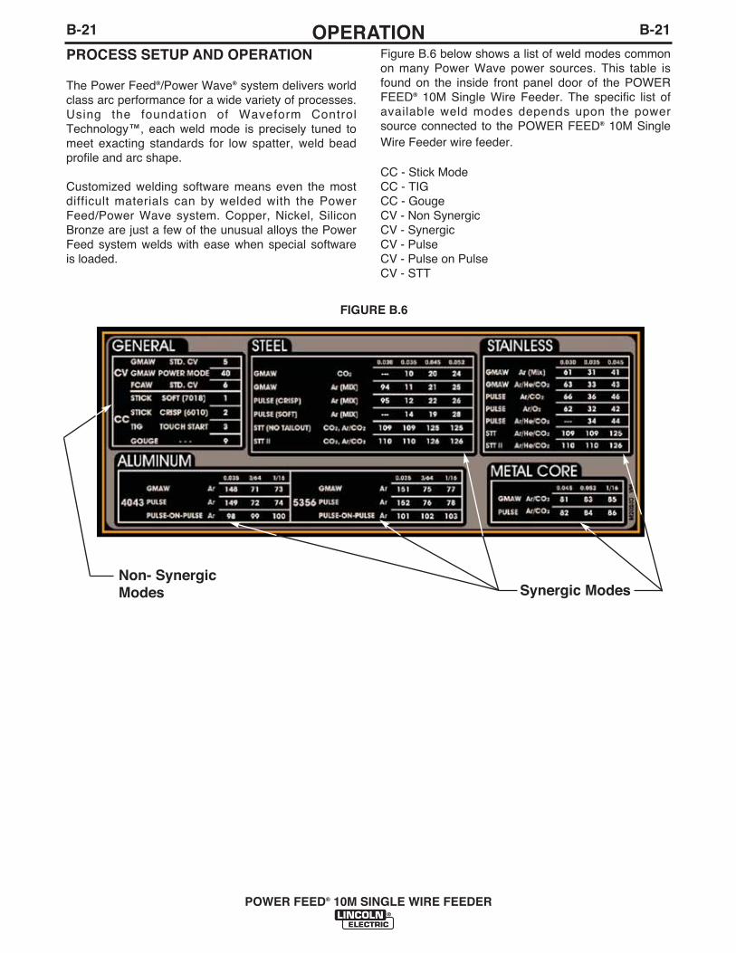
PROCESS SETUP AND OPERATION
The Power Feed®/Power Wave® system delivers worldclass arc performance for a wide variety of processes.Using the foundation of Waveform ControlTechnology™, each weld mode is precisely tuned tomeet exacting standards for low spatter, weld beadprofile and arc shape.
Customized welding software means even the mostdifficult materials can by welded with the PowerFeed/Power Wave system. Copper, Nickel, SiliconBronze are just a few of the unusual alloys the PowerFeed system welds with ease when special softwareis loaded.
Figure B.6 below shows a list of weld modes commonon many Power Wave power sources. This table isfound on the inside front panel door of the POWERFEED® 10M Single Wire Feeder. The specific list ofavailable weld modes depends upon the powersource connected to the POWER FEED® 10M SingleWire Feeder wire feeder.
CC - Stick ModeCC - TIGCC - GougeCV - Non SynergicCV - SynergicCV - Pulse CV - Pulse on PulseCV - STT
FIGURE B.6
B-21OPERATIONB-21
POWER FEED® 10M SINGLE WIRE FEEDER
Non- SynergicModes Synergic Modes
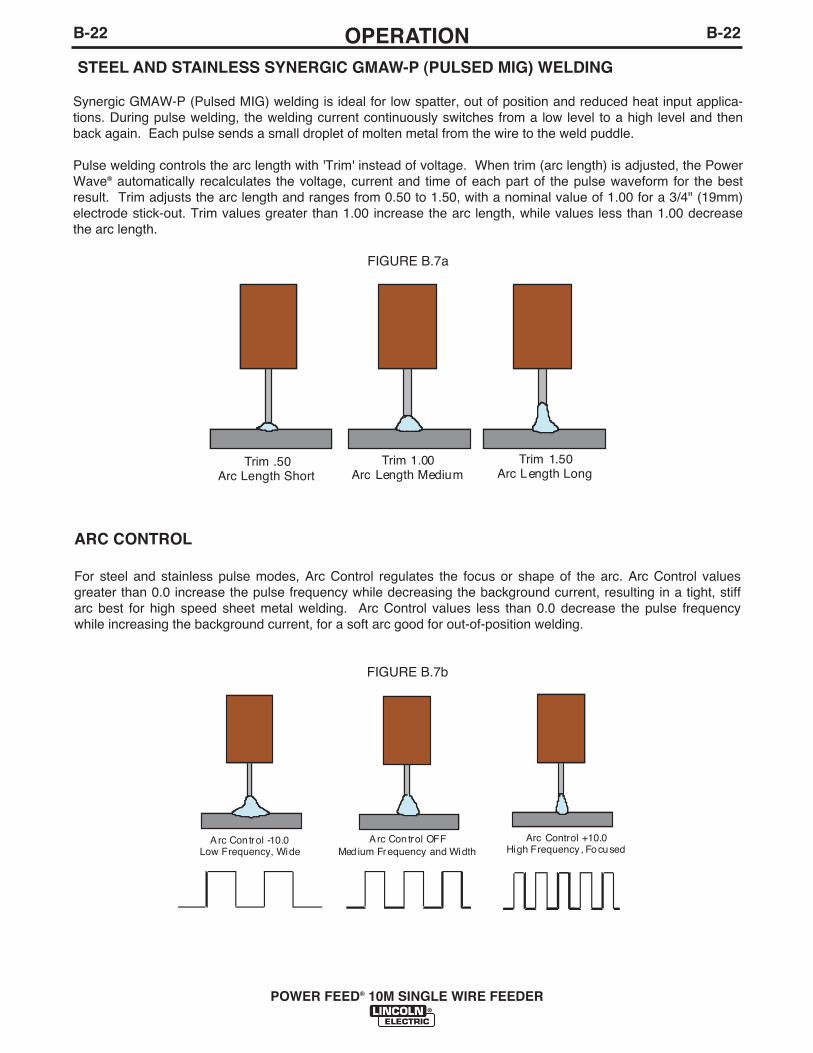
B-22OPERATIONB-22
POWER FEED® 10M SINGLE WIRE FEEDER
STEEL AND STAINLESS SYNERGIC GMAW-P (PULSED MIG) WELDING
Synergic GMAW-P (Pulsed MIG) welding is ideal for low spatter, out of position and reduced heat input applica-tions. During pulse welding, the welding current continuously switches from a low level to a high level and thenback again. Each pulse sends a small droplet of molten metal from the wire to the weld puddle.
Pulse welding controls the arc length with 'Trim' instead of voltage. When trim (arc length) is adjusted, the PowerWave® automatically recalculates the voltage, current and time of each part of the pulse waveform for the bestresult. Trim adjusts the arc length and ranges from 0.50 to 1.50, with a nominal value of 1.00 for a 3/4" (19mm)electrode stick-out. Trim values greater than 1.00 increase the arc length, while values less than 1.00 decreasethe arc length.
FIGURE B.7a
ARC CONTROL
For steel and stainless pulse modes, Arc Control regulates the focus or shape of the arc. Arc Control valuesgreater than 0.0 increase the pulse frequency while decreasing the background current, resulting in a tight, stiffarc best for high speed sheet metal welding. Arc Control values less than 0.0 decrease the pulse frequencywhile increasing the background current, for a soft arc good for out-of-position welding.
FIGURE B.7b
Trim .50Arc Length Short
Trim 1.00Arc Length Medium
Trim 1.50Arc Length Long
A rc Control OFFMed ium Frequency and Width
Arc Control +10.0Hi gh Frequency , Focused
A rc Control -10.0Low Frequency, Wide

B-23OPERATIONB-23
POWER FEED® 10M SINGLE WIRE FEEDER
ALUMINUM SYNERGIC GMAW-P (PULSEDMIG)AND GMAW-PP (PULSE ON PULSE)WELDING
The POWER FEED® 10M Single Wire Feeder andPower Wave welding power source combine to readilyproduce top quality aluminum welds with excellentappearance, little spatter and good bead shape. Push-pull guns are available for consistent feeding whenwelding a long distance away from the wire feeder.
Pulse-on-Pulse WeldingThe Power Wave® system offers both traditional pulseand Pulse-on-Pulse™. Pulse-on-Pulse (GMAW-PP) isan exclusive waveform for aluminum welding. Use itto make welds with a "stacked dime" appearance,similar to GTAW welds.
FIGURE B.7c
The pulsing frequency is adjustable. Changing the fre-quency modulation (or arc control) of the waveformchanges the ripple spacing. Faster travel speeds maybe achieved by using higher values of frequency mod-ulation.
FIGURE B.7d
Frequency Modulation = -10Wide weld and ripple spacing, slow travel speed.
Frequency Modulation = 10Narrow weld and ripple spacing, fast travel speed.
FIGURE B.7e
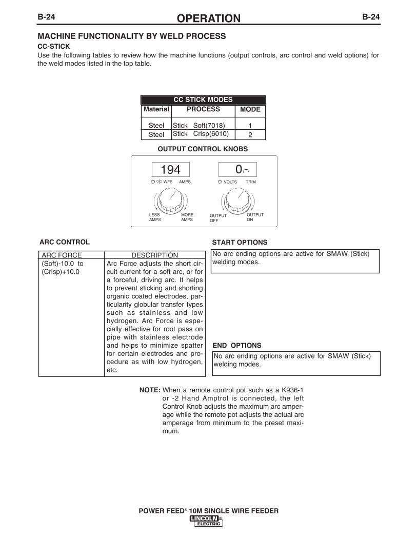
B-24OPERATIONB-24
POWER FEED® 10M SINGLE WIRE FEEDER
ARC FORCE(Soft)-10.0 to(Crisp)+10.0
DESCRIPTIONArc Force adjusts the short cir-cuit current for a soft arc, or fora forceful, driving arc. It helpsto prevent sticking and shortingorganic coated electrodes, par-ticularity globular transfer typessuch as stainless and lowhydrogen. Arc Force is espe-cially effective for root pass onpipe with stainless electrodeand helps to minimize spatterfor certain electrodes and pro-cedure as with low hydrogen,etc.
START OPTIONS
No arc ending options are active for SMAW (Stick)welding modes.
No arc ending options are active for SMAW (Stick)welding modes.
END OPTIONS
ARC CONTROL
194 0WFS AMPS VOLTS TRIM
LESSAMPS
MOREAMPS
OUTPUTOFF
OUTPUTON
Material
SteelSteel
PROCESS
Stick Soft(7018)Stick Crisp(6010)
MODE
12
MACHINE FUNCTIONALITY BY WELD PROCESSCC-STICKUse the following tables to review how the machine functions (output controls, arc control and weld options) forthe weld modes listed in the top table.
OUTPUT CONTROL KNOBS
CC STICK MODES
NOTE: When a remote control pot such as a K936-1or -2 Hand Amptrol is connected, the leftControl Knob adjusts the maximum arc amper-age while the remote pot adjusts the actual arcamperage from minimum to the preset maxi-mum.

Material
SteelSteelSteel
PROCESS
GMAW, CVGMAW, POWER MODE
FCAW, CV
WELD MODE
5406
CV NON-SYNERGIC MODES
B-25OPERATIONB-25
POWER FEED® 10M SINGLE WIRE FEEDER
DESCRIPTIONArc Force adjusts the short cir-cuit current for a soft arc, or fora forceful, digging arc.
ARC CONTROL
300 25.3WFS AMPS VOLTS TRIM
LESSWFS
MOREWFS
LESSVOLTS
MOREVOLTS
MACHINE FUNCTIONALITY BY WELD PROCESSCV GMAW/FCAW (NON-SYNERGIC)Use the following tables to review how the machine functions (output controls, arc control, Start options and weldoptions) for the weld modes listed in the top table.
OUTPUT CONTROL KNOBS, WELD MODE 5 & 6
200 2.0WFS AMPS VOLTS TRIM
LESSWFS
MOREWFS
SHORTERARC
LONGERARC
OUTPUT CONTROL KNOBS, WELD MODE 40
EFFECT / RANGE(Soft)-10.0 to(Crisp)+10.0
EFFECT / RANGE
Preflow Time0 to 25.0 seconds
Run-In WFS:Off, 30 to150 in/min.
Start Procedure0 to 10 seconds
DESCRIPTION
Adjusts the time the gas flowsafter the trigger is pulled andprior to feeding.Run-In sets the wire feedspeed from the time the triggeris pulled until an arc is estab-lished.The Start Procedure controls theWFS and Volts for a specified timeat the beginning of the weld.During the start time, the machinewill ramp up or down from theStart Procedure to the presetWelding Procedure.
START OPTIONSThe start Options available in these Non-Synergic CV weldmodes, their adjustment range and function are as follows :
EFFECT / RANGE
Spot Timer:0 to 120.0 Seconds
Postflow Time0 to 25.0 secondsCrater Procedure(0 TO 10.0 SECONDS)
Burnback: 0 to .25 Seconds
DESCRIPTION
Adjusts the time welding will continueeven if tigger is still pulled. This optionhas no effect in 4-Step Trigger Mode.Adjusts the time that shielding gasflows after the welding output turns off.Crater Procedure controls the WFSand Volts for a specified time at theend of the weld after the trigger isreleased. During the Crater time, themachine will ramp up or down from theWeld Procedure to the CraterProcedure.The burnback time is the amount oftime that the weld output continuesafter the wire stops feeding. It preventsthe wire from sticking in the puddle andprepares the end of the wire for thenext arc start.
END OPTIONS
START OPTIONS
END OPTIONS
SET
SETUPIR PORT
STD CV MIG
WAVEFORM CONTROL TECHNOLOGY
5
WELD MODE
ARC CONTROL

B-26OPERATIONB-26
MACHINE FUNCTIONALITY BY WELD PROCESSGMAW (SYNERGIC)Use the following tables to review how the machine functions (output controls, arc control, Start options and weldoptions) for the weld modes listed in the top table.
POWER FEED® 10M SINGLE WIRE FEEDER
EFFECT / RANGEPINCH EFFECT(-10.0 to +10.0)
DESCRIPTIONAdjust the short circuit currentto create a soft arc, or a force-ful, digging arc.
EFFECT / RANGE
Preflow Time0 to 25 seconds
Run-in WFS:Off, 30 to150 in/min.
Start Procedure
DESCRIPTION
Adjusts the time the gas flowsafter the trigger is pulled andprior to feeding.Run-In sets the wire feedspeed from the time the triggeris pulled until an arc is estab-lished.The Start Procedure controlsthe WFS. Trim at a specifiedtime at the beginning of theweld. During the start time, themachine will ramp up or downfrom the Start Procedure to thepreset Welding Procedure.
START OPTIONSThe start Options available in these synergic CV weldmodes, their adjustment range and function are asfollows :
ARC CONTROL
OUTPUT CONTROL KNOBS
EFFECT / RANGE
Spot Timer:0 to 120.0 Seconds
Postflow Time0 to 10 seconds
Burnback:0 to .25 Seconds
Crater Procedure
DESCRIPTION
Adjusts the time welding will continueeven if tigger is still pulled. This optionhas no effect in 4-Step Trigger Mode.Adjusts the time that shieldinggas flows after the welding out-put turns off.The burnback time is theamount of time that the weldoutput continues after the wirestops feeding. It prevents thewire from sticking in the puddleand prepares the end of thewire for the next arc start.Crater Procedure controls theWFS and volts for a specifiedtime at the end of the weldafter the trigger is released.During the Crater time, themachine will ramp up or downfrom the Weld Procedure tothe Crater Procedure.
END OPTIONS
200 26.3WFS AMPS VOLTS TRIM
LESSWFS
MOREWFS
LESSVOLTS
MOREVOLTS
MATERIAL
SteelSteel
StainlessStainless
Aluminum 4043 Aluminum 5356
Metal Core
GAS
CO2
Ar(Mix)Ar(Mix)
Ar/He/CO2
ArAr
Ar/CO2
PROCESS
GMAWGMAWGMAWGMAW
TIGTIG
GMAW
WIRE SIZE0.030 0.035 0.045 0.052
--- 10 20 2494 11 21 2561 31 41 ---63 33 43 ------ 148 71 ------ 151 75 ------ --- --- ---
SYNERGIC CV MODES

B-27OPERATIONB-27
POWER FEED® 10M SINGLE WIRE FEEDER
ARC CONTROL
PULSEFREQUENCY:(Low)-10.0 to(High)+10.0
DESCRIPTION
For Pulse modes, Arc Controlchanges the pulsing frequency.When the frequency changes,the Power Wave system auto-matically adjusts the back-ground current to maintain asimilar heat input into the weld.Low frequencies give more con-trol over the puddle and highfrequencies minimize spatter.
PREFLOW TIME
0 to 10 seconds
RUN-IN WFS:Off, 50 to150 in/min.
Start Procedure
DESCRIPTION
Adjusts the time the gas flowsafter the trigger is pulled andprior to feeding wire.
Run-in sets the wire feedspeed from the time the triggeris pulled until an arc is estab-lished.The Start Procedure controlsthe WFS. Trim at a specifiedtime at the beginning of theweld. During the start time, themachine will ramp up or downfrom the Start Procedure to thepreset Welding Procedure.
START OPTIONS
MACHINE FUNCTIONALITY BY WELD PROCESSPULSE AND PULSE-ON-PULSE (SYNERGIC)Use the following tables to review how the machine functions (output controls, arc control, Start options and weldoptions) for the weld modes listed in the top table.
OUTPUT CONTROL KNOBS
WFS AMPS VOLTS TRIM
LESSWFS
MOREWFS
LESSTRIM
MORETRIM
MATERIAL
ALUMINUM 4043ALUMINUM 4043ALUMINUM 5356 ALUMINUM 5356
GAS
ArArArAr
PROCESS
Pulse Pulse-on-Pulse
PulsePulse-on-Pulse
WIRE SIZE0.035 3/64 1/16
149 72 7498 99 100152 76 78101 102 103
PULSE AND PULSE-0N-PULSE MODES
EFFECT / RANGE
Postflow Time:0 to 10 seconds
Burnback: 0 to .25Seconds
Crater Procedure
Spot Timer:0 to 10 Seconds
FUNCTION
Adjusts the time that shieldinggas flows after the welding out-put turns off.The burnback time is theamount of time that the weldoutput continues after the wirestops feeding. It prevents thewire from sticking in the puddleand prepares the end of thewire for the next arc start.Crater Procedure controls theWFS and volts for a specifiedtime at the end of the weldafter the trigger is released.During the Crater time, themachine will ramp up or downfrom the Weld Procedure tothe Crater Procedure.
Adjusts the time welding willcontinue even if tigger is stillpulled. This option has noeffect in 4-Step Trigger Mode.
END OPTIONS

B-28OPERATIONB-28
POWER FEED® 10M SINGLE WIRE FEEDER
200 ----WFS AMPS VOLTS TRIM
LESSDEPOSITION
MOREDEPOSITION
EFFECT / RANGE
PEAK CURRENT
BACKGROUND CUR-RENT
TAIL OUT(STT ll MODES ONLY)
DESCRIPTION
Peak Current acts similar to an arcpinch control. Peak Current setsthe arc length and promotes goodfusion. Higher peak current levelswil l cause the arc to broadenmomentarily while increasing arclength. If set too high, globulartransfer may occur. Setting it toolow may cause instability and wirestubbing. Best practice is to adjustfor minimum spatter and puddleagitation.
Background Current controls theoverall heat input in the weld.
Tail out provides additional powerwithout the molten droplet becom-ing too large. Increase as neces-sary to add heat input withoutincreasing arc length. Often thisresults in faster travel speeds.Note that as tail out increases, thepeak current and/or backgroundcurrent may need to be reduced.
MACHINE FUNCTIONALITY BY WELD PROCESSSTT AND STT II (NONN-SYNERGIC)Use the following tables to review how the machine functions (output controls, arc control, Start options and weldoptions) for the weld modes listed in the top table.
OUTPUT CONTROL KNOBS (There is no Voltage control when STT welding.)
PREFLOW TIME
0 to 10 seconds
RUN-IN WFS:Off, 50 to150 in/min.
Start Procedure
FUNCTION
Adjusts the time the gas flowsafter the trigger is pulled andprior to feeding wire.Run-in sets the wire feedspeed from the time the triggeris pulled until an arc is estab-lished.The Start Procedure is notcommonly used with STT pro-cedures.
START OPTIONS
PARAMETER RANGESpot Timer:0 to 120.0 Seconds
Postflow Time:0 to 25.0 seconds
Crater Procedure
Burnback:0 to .25 Seconds
FUNCTIONAdjusts the time welding will continueeven if tigger is still pulled. This optionhas no effect in 4-Step Trigger Mode.
Adjusts the time that shielding gasflows after the welding outputturns off.
Crater Procedure is not commonlyused in STT wels procedures.
The burnback time is theamount of time that the weldoutput continues after the wirestops feeding. It prevents thewire from sticking in the puddleand prepares the end of thewire for the next arc start.
END OPTIONS
ARC CONTROL
MA T E R IA L
SteelStainless
(With Hot Start)
Steel Stainless
(Synergic STT)SteelSteel
Stainless Stainless
(Synergic STT,Open Root)
Steel Stainless
G A S
CO2, Ar/CO2
Ar/He/CO2
CO2, Ar/CO2
Ar/He/CO2
CO2
Ar/CO2
Ar/He/CO2
Ar/CO2
CO2
Ar/He/CO2
WIR E S IZE0.035 0.045 0.052 110 126 126110 126 126
123 124 124123 124 124
111 117 120112 118 121127 129 -----131 133 -----
113 119 122135 137 -----
G MA W-S T T WE L D MODE
START OPTIONS
END OPTIONS
STEEL .035”
SET
SETUP
IR PORT
STT
WAVEFORM CONTROL TECHNOLOGY
110
WELD MODE
ARC CONTROL
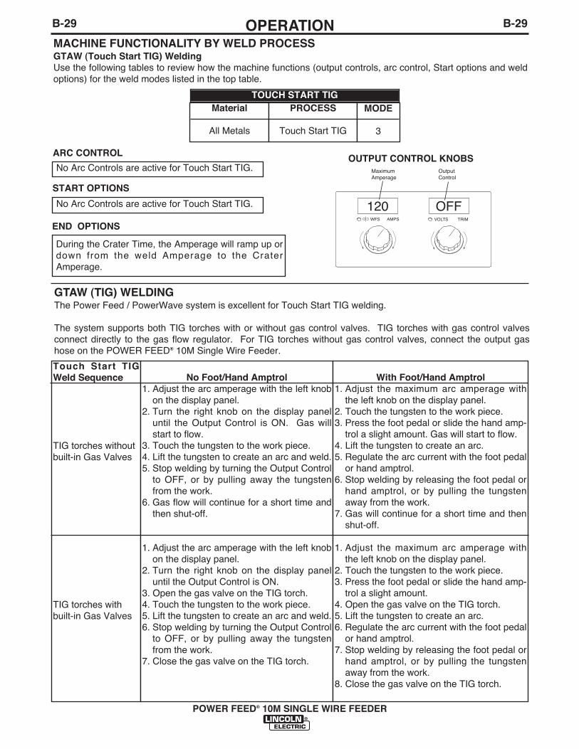
B-29OPERATIONB-29
POWER FEED® 10M SINGLE WIRE FEEDER
MACHINE FUNCTIONALITY BY WELD PROCESSGTAW (Touch Start TIG) WeldingUse the following tables to review how the machine functions (output controls, arc control, Start options and weldoptions) for the weld modes listed in the top table.
120 OFFWFS AMPS VOLTS TRIM
Maximum Amperage
OutputControl
Material
All Metals
PROCESS
Touch Start TIG
MODE
3
OUTPUT CONTROL KNOBS
TOUCH START TIG
No Arc Controls are active for Touch Start TIG.
No Arc Controls are active for Touch Start TIG.
START OPTIONS
During the Crater Time, the Amperage will ramp up ordown from the weld Amperage to the CraterAmperage.
END OPTIONS
ARC CONTROL
GTAW (TIG) WELDINGThe Power Feed / PowerWave system is excellent for Touch Start TIG welding.
The system supports both TIG torches with or without gas control valves. TIG torches with gas control valvesconnect directly to the gas flow regulator. For TIG torches without gas control valves, connect the output gashose on the POWER FEED® 10M Single Wire Feeder.
Touch Start TIGWeld Sequence
TIG torches withoutbuilt-in Gas Valves
TIG torches withbuilt-in Gas Valves
No Foot/Hand Amptrol1. Adjust the arc amperage with the left knob
on the display panel.2. Turn the right knob on the display panel
until the Output Control is ON. Gas willstart to flow.
3. Touch the tungsten to the work piece.4. Lift the tungsten to create an arc and weld.5. Stop welding by turning the Output Control
to OFF, or by pulling away the tungstenfrom the work.
6. Gas flow will continue for a short time andthen shut-off.
1. Adjust the arc amperage with the left knobon the display panel.
2. Turn the right knob on the display paneluntil the Output Control is ON.
3. Open the gas valve on the TIG torch.4. Touch the tungsten to the work piece.5. Lift the tungsten to create an arc and weld.6. Stop welding by turning the Output Control
to OFF, or by pulling away the tungstenfrom the work.
7. Close the gas valve on the TIG torch.
With Foot/Hand Amptrol1. Adjust the maximum arc amperage with
the left knob on the display panel.2. Touch the tungsten to the work piece.3. Press the foot pedal or slide the hand amp-
trol a slight amount. Gas will start to flow.4. Lift the tungsten to create an arc.5. Regulate the arc current with the foot pedal
or hand amptrol.6. Stop welding by releasing the foot pedal or
hand amptrol, or by pulling the tungstenaway from the work.
7. Gas will continue for a short time and thenshut-off.
1. Adjust the maximum arc amperage withthe left knob on the display panel.
2. Touch the tungsten to the work piece.3. Press the foot pedal or slide the hand amp-
trol a slight amount.4. Open the gas valve on the TIG torch.5. Lift the tungsten to create an arc.6. Regulate the arc current with the foot pedal
or hand amptrol.7. Stop welding by releasing the foot pedal or
hand amptrol, or by pulling the tungstenaway from the work.
8. Close the gas valve on the TIG torch.

B-30OPERATIONB-30
WELD MODE SEARCHING
The Weld Mode Search feature allows the selection ofa welding mode based on certain criteria (wire size,process type, etc.).
SEARCHING FOR A WELD MODE
To search for a mode, turn the control knob until“Weld Mode Search” is displayed. This will appear inbetween the highest and the lowest weld mode num-bers.
Once “Weld Mode Search” is displayed, pressing theright pushbutton labeled “Begin” will start the searchprocess.
During the search process, pressing the right pushbut-ton typically acts as a “next” button and the left push-button typically acts as a “back” button.
Rotate the control knob then press the right pushbut-ton to select relevant welding details such as weldingprocess, wire type, wire size, etc.
When the final selection is made, the PF10M™ willautomatically change to the weld mode found by theWeld Mode Search process.
Earlier products may not have this feature. To acti-vate this feature, a software update may be neededfrom www.powerwavesoftware.com
USER MEMORIES
Recall a memory with memory buttons
To recall a user memory, press one of the six usermemory buttons. The memory is recalled when thebutton is released. Do not hold the button for morethan two seconds when recalling a user memory.
Recall a memory with the gun trigger
If desired, memories 2 through 6 can be recalled withthe gun trigger. For example, to recall memory 3,quickly pull and release the gun trigger 3 times withoutwelding.
Note: the POWER FEED® 10M Single Wire Feeder isfactory set with this feature disabled. Use the SETUPmenu and change P.4 to enable memory recall withthe gun trigger.
Save a memory with memory buttons
To save a memory, press and hold the desired memo-ry button for two seconds. When the button is initiallypressed, the corresponding LED will illuminate. Aftertwo seconds, the LED will turn off. Do not hold thebutton for more than 5 seconds when saving a usermemory.
Note that memories may be locked in the Setup menuto prevent accidental overwrite of the memories. If anattempt is made to save a memory when memory sav-ing is locked, the message "Memory save isDisabled!" will appear briefly in the MSP4 display.
POWER FEED® 10M SINGLE WIRE FEEDER
HOLD 2 SECONDS TO SAVE
PROCEDURE
MEMORY
A GUN B 1
4
2
5
3
6
M M
RECALLPRESS 1SECOND
SAVEPRESS 2
SECONDS
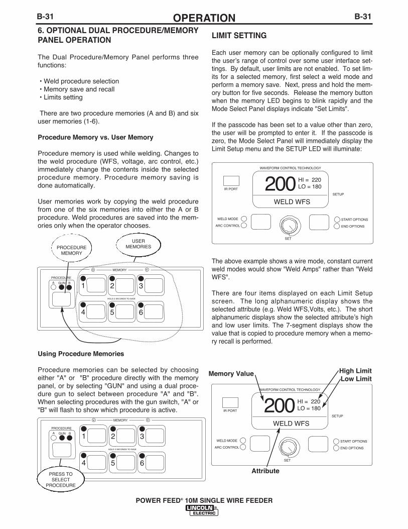
B-31OPERATIONB-31
POWER FEED® 10M SINGLE WIRE FEEDER
6. OPTIONAL DUAL PROCEDURE/MEMORYPANEL OPERATION
The Dual Procedure/Memory Panel performs threefunctions:
• Weld procedure selection• Memory save and recall• Limits setting
There are two procedure memories (A and B) and sixuser memories (1-6).
Procedure Memory vs. User Memory
Procedure memory is used while welding. Changes tothe weld procedure (WFS, voltage, arc control, etc.)immediately change the contents inside the selectedprocedure memory. Procedure memory saving isdone automatically.
User memories work by copying the weld procedurefrom one of the six memories into either the A or Bprocedure. Weld procedures are saved into the mem-ories only when the operator chooses.
Using Procedure Memories
Procedure memories can be selected by choosingeither "A" or "B" procedure directly with the memorypanel, or by selecting "GUN" and using a dual proce-dure gun to select between procedure "A" and "B".When selecting procedures with the gun switch, "A" or"B" will flash to show which procedure is active.
HOLD 2 SECONDS TO SAVE
PROCEDURE
MEMORY
A GUN B 1
4
2
5
3
6
M M
HOLD 2 SECONDS TO SAVE
PROCEDURE
MEMORY
A GUN B 1
4
2
5
3
6
M M
PROCEDUREMEMORY
PRESS TOSELECT
PROCEDURE
USERMEMORIES
LIMIT SETTING
Each user memory can be optionally configured to limitthe userʼs range of control over some user interface set-tings. By default, user limits are not enabled. To set lim-its for a selected memory, first select a weld mode andperform a memory save. Next, press and hold the mem-ory button for five seconds. Release the memory buttonwhen the memory LED begins to blink rapidly and theMode Select Panel displays indicate "Set Limits".
If the passcode has been set to a value other than zero,the user will be prompted to enter it. If the passcode iszero, the Mode Select Panel will immediately display theLimit Setup menu and the SETUP LED will illuminate:
The above example shows a wire mode, constant currentweld modes would show "Weld Amps" rather than "WeldWFS".
There are four items displayed on each Limit Setupscreen. The long alphanumeric display shows theselected attribute (e.g. Weld WFS,Volts, etc.). The shortalphanumeric displays show the selected attributeʼs highand low user limits. The 7-segment displays show thevalue that is copied to procedure memory when a memo-ry recall is performed.
START OPTIONS
END OPTIONS
HI = 220LO = 180
SET
SETUP
IR PORT
WELD WFS
WAVEFORM CONTROL TECHNOLOGY
200
WELD MODE
ARC CONTROL
START OPTIONS
END OPTIONS
HI = 220LO = 180
SET
SETUP
IR PORT
WELD WFS
WAVEFORM CONTROL TECHNOLOGY
200
WELD MODE
ARC CONTROL
Memory Value
Attribute
High LimitLow Limit

B-32OPERATIONB-32
POWER FEED® 10M SINGLE WIRE FEEDER
One of these four items will blink to indicate which itemwill change when the Mode Select Panel Knob is rotated.Initially, the selected item will be the attribute. To selectthe high limit, press either Mode Select Panel button andthe high limit value will begin to blink. Pressing eitherMode Select Panel button again will cause the memoryvalue to blink, pressing a third time will cause the lowlimit to blink.
Weld modes cannot be selected from the Limits Setupmenu; the mode must be selected and saved to memoryprior to entering the Limits Setup menu.
The memory value, high and low limit values are boundby the limits of the machine. For example, weld mode 49may allow the wire feed speed to be adjusted between100 and 700 in/min. These are referred to as "machinelimits". Machine limits can vary between power sourcesand are also weld mode dependent.
The memory value must always be less than or equal tothe high limit and greater than or equal to the low limit.The high limit must always be greater than or equal tothe low limit and the low limit must always be less than orequal to the high limit. The rules are enforced automati-cally. If the low limit is increased above the memoryvalue, the memory value will automatically increase.
To lock an attribute to a specific value, set the high andlow limits to the desired value. The user will not be ableto change it.
After setting limits, press the memory button that is flash-ing. The Mode Select Panel displays will prompt theuser to save or discard the limit changes just made.
By pressing the Mode Select Panel button labeled YES,changes to limits are saved and user limits are automati-cally enabled. By pressing NO, any changes made tolimits are discarded and the limit enable/disable state isnot changed.
To enable or disable limits that have been established forany memory, press and hold the respective memory but-ton in for more than 10 seconds until the Mode SelectPanel displays "Enable Limits?" Pressing "Yes" will usethe established limits, while pressing "No" will ignore theestablished limits. The limits that have been set for anymemory location will not be erased if they are disabled.
START OPTIONS
END OPTIONS
SET
SETUP
IR PORT
Yes No
WAVEFORM CONTROL TECHNOLOGY
EnableLimits?
WELD MODE
ARC CONTROL
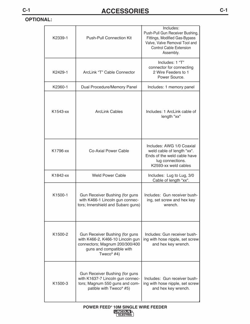
C-1ACCESSORIESC-1
POWER FEED® 10M SINGLE WIRE FEEDER
OPTIONAL:
K2339-1
K2429-1
K2360-1
K1543-xx
K1796-xx
K1842-xx
K1500-1
K1500-2
K1500-3
Push-Pull Connection Kit
ArcLink “T” Cable Connector
Dual Procedure/Memory Panel
ArcLink Cables
Co-Axial Power Cable
Weld Power Cable
Gun Receiver Bushing (for gunswith K466-1 Lincoln gun connec-
tors; Innershield and Subarc guns)
Gun Receiver Bushing (for gunswith K466-2, K466-10 Lincoln gunconnectors; Magnum 200/300/400
guns and compatible withTweco® #4)
Gun Receiver Bushing (for gunswith K1637-7 Lincoln gun connec-tors; Magnum 550 guns and com-
patible with Tweco® #5)
Includes: Push-Pull Gun Receiver Bushing,
Fittings, Modified Gas-BypassValve, Valve Removal Tool and
Control Cable ExtensionAssembly.
Includes: 1 “T”connector for connecting
2 Wire Feeders to 1 Power Source.
Includes: 1 memory panel
Includes: 1 ArcLink cable oflength "xx"
Includes: AWG 1/0 Coaxialweld cable of length "xx".
Ends of the weld cable havelug connections.
K2593-xx weld cables
Includes: Lug to Lug, 3/0Cable of length "xx".
Includes: Gun receiver bush-ing, set screw and hex key
wrench.
Includes: Gun receiver bush-ing with hose nipple, set screw
and hex key wrench.
Includes: Gun receiver bush-ing with hose nipple, set screw
and hex key wrench.

C-2ACCESSORIESC-2
POWER FEED® 10M SINGLE WIRE FEEDER
K1500-4
K1500-5
K489-9
K466-2
K613-7
K1546-1
K1546-2
K1733-1
K870-1
K936-1
K936-2
Gun Receiver Bushing (for gunwith K466-3 Lincoln gun connec-
tors; compatible with Miller® guns.)
Gun Receiver Bushing (compatiblewith Oxo® guns.)
Gun Receiver Bushing (for LincolnFast-Mate guns.)
Magnum 200/300/400 to K1500-2Adapter
Magnum 550 to K1500-3 Adapter
Incoming Bushing, Lincoln Conduit.025- 1/16"
Incoming Bushing, Lincoln Conduit1/16-1/8"
Wire Straightener
Foot Amptrol
Hand Amptrol LA-9/-17/LW20
Hand Amptrol LA-26/LW-18
Includes: Gun receiver bush-ing with hose nipple, set screw
and hex key wrench.
Includes: Gun receiver bush-ing with hose nipple, 4 guidetubes, set screw and hex key
wrench.
Includes: Gun receiver bush-ing with trigger connector.
Includes: Gun adapter, cotterpin, hex key wrench, wrench.
Includes: Trigger adapter, gunadapter and hex key wrench.
Includes: Incoming bushingand hex key wrench.
Includes: Incoming bushingand hex key wrench.
Includes: Wire Straightener.
Includes: F oot Amptrol
Includes:Hand AmptrolLA-9/-17/LW20
Includes:Hand AmptrolLA-26/LW-18
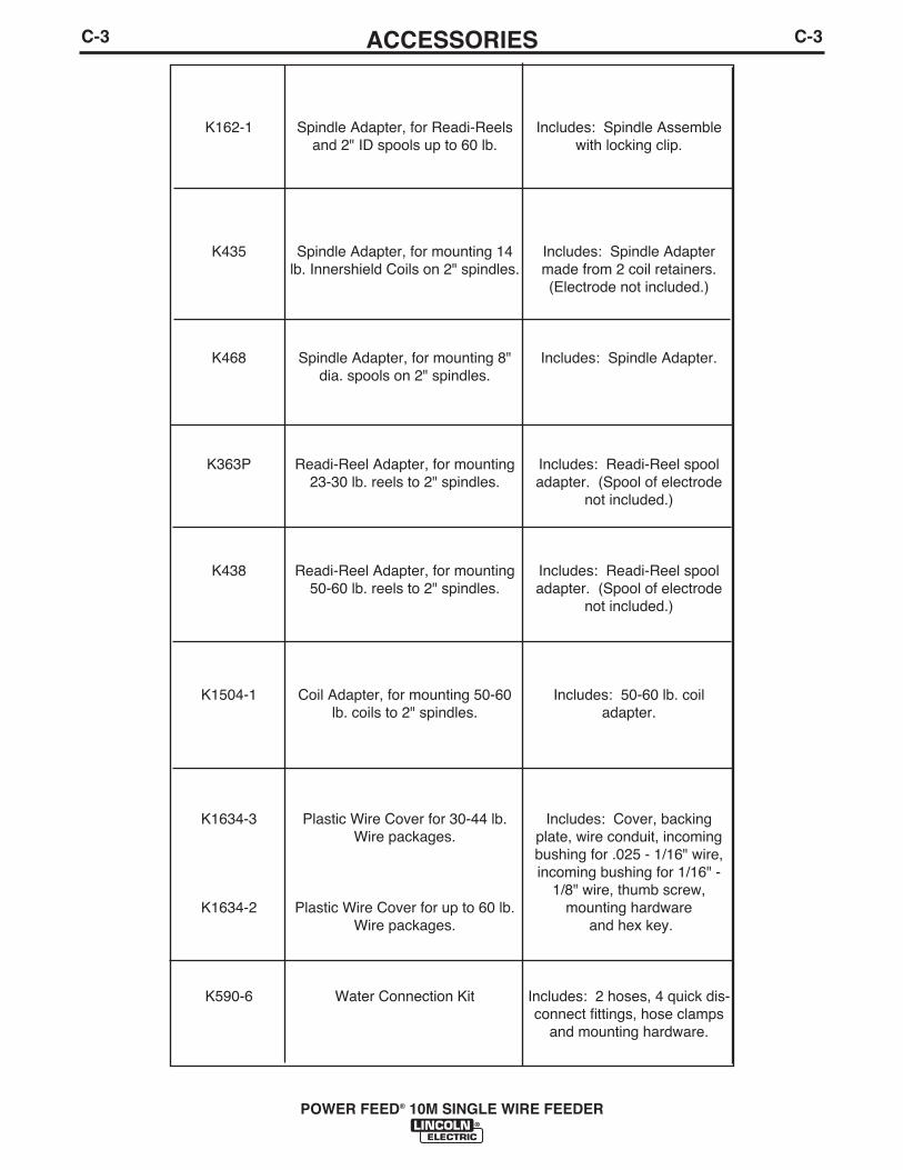
C-3ACCESSORIESC-3
POWER FEED® 10M SINGLE WIRE FEEDER
K162-1
K435
K468
K363P
K438
K1504-1
K1634-3
K1634-2
K590-6
Spindle Adapter, for Readi-Reelsand 2" ID spools up to 60 lb.
Spindle Adapter, for mounting 14lb. Innershield Coils on 2" spindles.
Spindle Adapter, for mounting 8"dia. spools on 2" spindles.
Readi-Reel Adapter, for mounting23-30 lb. reels to 2" spindles.
Readi-Reel Adapter, for mounting50-60 lb. reels to 2" spindles.
Coil Adapter, for mounting 50-60lb. coils to 2" spindles.
Plastic Wire Cover for 30-44 lb.Wire packages.
Plastic Wire Cover for up to 60 lb.Wire packages.
Water Connection Kit
Includes: Spindle Assemblewith locking clip.
Includes: Spindle Adaptermade from 2 coil retainers.(Electrode not included.)
Includes: Spindle Adapter.
Includes: Readi-Reel spooladapter. (Spool of electrode
not included.)
Includes: Readi-Reel spooladapter. (Spool of electrode
not included.)
Includes: 50-60 lb. coiladapter.
Includes: Cover, backingplate, wire conduit, incomingbushing for .025 - 1/16" wire,incoming bushing for 1/16" -
1/8" wire, thumb screw,mounting hardware
and hex key.
Includes: 2 hoses, 4 quick dis-connect fittings, hose clamps
and mounting hardware.

D-1MAINTENANCED-1
POWER FEED® 10M SINGLE WIRE FEEDER
SAFETY PRECAUTIONS
WARNING
Observe all additional Safety Guidelines detailedthroughout this manual.
ELECTRIC SHOCK can kill.• Do not touch electrically live parts such
as output terminals or internal wiring.
• When inching with gun trigger, electrode anddrive mechanism are “hot” to work andground and could remain energized severalseconds after the gun trigger is released.
• Turn OFF input power at welding powersource before installation or changingdrive roll and/or guide tubes.
• Welding power source must be connectedto system ground per the NationalElectrical Code or any applicable localcodes.
• Only qualified personnel should perform maintenance work.
ROUTINE MAINTENANCE
• Check weld cables, control cables and gas hosesfor cuts.
• Clean and tighten all weld terminals.
• Inspect and clean drive rolls and inner wire guideand replace if worn.
PERIODIC MAINTENANCE
• Blow out or vacuum the inside of the feeder.
• Every six months check the motor brushes.Replace them if they are less than 1/4" long.
• Every year inspect the gearbox and coat the gearteeth with a moly-disulfide filled grease. DO NOTuse graphite grease.
CALIBRATION SPECIFICATION
All calibration is factory set on the POWER FEED®
10M Single Wire Feeder.
To verify the wire feed speed:
• Assemble a .045 (1.2mm) drive roll kit into thePOWER FEED® 10M Single Wire Feeder.
• Load a spool of .045 (1.2mm) electrode and threadthe electrode through the wire drive.
• Adjust the wire feed speed to 300 in/min(7.62m/min).
• Press the COLD FEED switch and measure theactual wire feed speed with a calibrated wire feedspeed tachometer.
• The measured wire feed speed should be within±2% of the set value.

E-1TROUBLESHOOTINGE-1
POWER FEED® 10M SINGLE WIRE FEEDER
If for any reason you do not understand the test procedures or are unable to perform the tests/repairs safely, contact yourLocal Lincoln Authorized Field Service Facility for technical troubleshooting assistance before you proceed.
CAUTION
This Troubleshooting Guide is provided to help youlocate and repair possible machine malfunctions.Simply follow the three-step procedure listed below.
Step 1. LOCATE PROBLEM (SYMPTOM).Look under the column labeled “PROBLEM (SYMP-TOMS)”. This column describes possible symptomsthat the machine may exhibit. Find the listing thatbest describes the symptom that the machine isexhibiting.
Step 2. POSSIBLE CAUSE.The second column labeled “POSSIBLE CAUSE” liststhe obvious external possibilities that may contributeto the machine symptom.
Step 3. RECOMMENDED COURSE OF ACTIONThis column provides a course of action for thePossible Cause, generally it states to contact yourlocal Lincoln Authorized Field Service Facility.
If you do not understand or are unable to perform theRecommended Course of Action safely, contact yourlocal Lincoln Authorized Field Service Facility.
HOW TO USE TROUBLESHOOTING GUIDE
Service and Repair should only be performed by Lincoln Electric Factory Trained Personnel.Unauthorized repairs performed on this equipment may result in danger to the technician andmachine operator and will invalidate your factory warranty. For your safety and to avoid ElectricalShock, please observe all safety notes and precautions detailed throughout this manual.
__________________________________________________________________________
WARNING

E-2TROUBLESHOOTINGE-2
POWER FEED® 10M SINGLE WIRE FEEDER
Observe all Safety Guidelines detailed throughout this manual
If for any reason you do not understand the test procedures or are unable to perform the tests/repairs safely, contact yourLocal Lincoln Authorized Field Service Facility for technical troubleshooting assistance before you proceed.
CAUTION
PROBLEMS(SYMPTOMS)
POSSIBLE CAUSE
RECOMMENDEDCOURSE OF ACTION
Err 006
Err 100
Err 31 Primary overcurrent
Err 32 Capacitor bank "A" undervoltage.
1. The wire feeder has not receiveda recognition command from thepower source. Verify the powersource is operating properly(Status light steady green.)
2. Check control cable for loose orbroken leads.
3. See power source InstructionManual.
1. The power source has issued ashutdown command. Verify thepower source is operating proper-ly. (Status light steady green.)
2. Check control cable for loose orbroken leads.
3. See power source instructionManual.
1. The power source has exceededinput current limits. Adjust thewelding procedure to reduce thecurrent draw. The welding proce-dure may exceed the capacity ofthe power source.
2. See the power source InstructionManual.
1. The power source input powermay be wired incorrectly. Verifythe power source reconnectpanel wiring matches the inputpower.
2. See the power source InstructionManual.
If all recommended possible areas ofmisadjustment have been checkedand the problem persists, Contactyour local Lincoln AuthorizedField Service Facility.
LINC-NET SYSTEM ERROR CODES
ARCLINK SYSTEM ERROR CODES
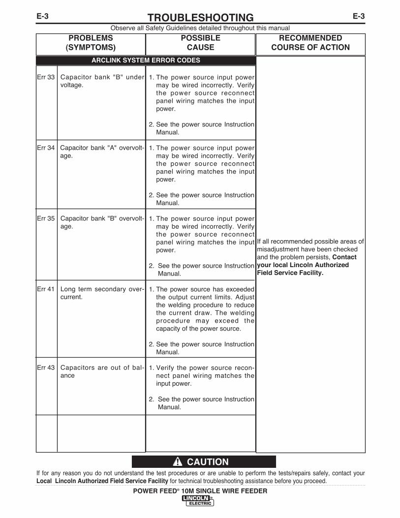
E-3TROUBLESHOOTINGE-3
POWER FEED® 10M SINGLE WIRE FEEDER
Observe all Safety Guidelines detailed throughout this manual
If for any reason you do not understand the test procedures or are unable to perform the tests/repairs safely, contact yourLocal Lincoln Authorized Field Service Facility for technical troubleshooting assistance before you proceed.
CAUTION
PROBLEMS(SYMPTOMS)
POSSIBLE CAUSE
RECOMMENDEDCOURSE OF ACTION
If all recommended possible areas ofmisadjustment have been checkedand the problem persists, Contactyour local Lincoln AuthorizedField Service Facility.
Err 33 Capacitor bank "B" undervoltage.
Err 34 Capacitor bank "A" overvolt-age.
Err 35 Capacitor bank "B" overvolt-age.
Err 41 Long term secondary over-current.
Err 43 Capacitors are out of bal-ance
1. The power source input powermay be wired incorrectly. Verifythe power source reconnectpanel wiring matches the inputpower.
2. See the power source InstructionManual.
1. The power source input powermay be wired incorrectly. Verifythe power source reconnectpanel wiring matches the inputpower.
2. See the power source InstructionManual.
1. The power source input powermay be wired incorrectly. Verifythe power source reconnectpanel wiring matches the inputpower.
2. See the power source InstructionManual.
1. The power source has exceededthe output current limits. Adjustthe welding procedure to reducethe current draw. The weldingprocedure may exceed thecapacity of the power source.
2. See the power source InstructionManual.
1. Verify the power source recon-nect panel wiring matches theinput power.
2. See the power source InstructionManual.
ARCLINK SYSTEM ERROR CODES

E-4TROUBLESHOOTINGE-4
POWER FEED® 10M SINGLE WIRE FEEDER
Observe all Safety Guidelines detailed throughout this manual
If for any reason you do not understand the test procedures or are unable to perform the tests/repairs safely, contact yourLocal Lincoln Authorized Field Service Facility for technical troubleshooting assistance before you proceed.
CAUTION
Err 44 Main CPU problem.
Err 53 Voltage sense loss.
Err 54 Short term secondary over-current.
Err 81 Motor overload, long term.
Err 82 Motor overload, short term.
Err 95 Spool gun or pull gun motoroverload.
Err 263 No usable weld modes.
1. Verify the ground connection tothe power source is wired correct-ly.
2. See the power source InstructionManual.
1. The wire drive motor has over-heated. Check that the electrodeslides easily through the gun andcable.
2. Remove tight bends from the gunand cable.
3. Check that the spindle brake isnot too tight.
4. Verify a high quality electrode isbeing used.
5. Wait for the error to reset and themotor to cool (approximately 1minute).
1. The wire drive motor current drawhas exceeded l imits, usuallybecause the motor is in a lockedrotor state. Check that motor canturn freely when idle arm is open.
2. Verify that the gears are free ofdebris and dirt.
1. The drive motor in the spool gunor push-pull gun is drawing toomuch current.
1. The power source does not haveany welding programs loaded.
If all recommended possible areas ofmisadjustment have been checkedand the problem persists, Contactyour local Lincoln AuthorizedField Service Facility.
ARCLINK SYSTEM ERROR CODES
PROBLEMS(SYMPTOMS)
POSSIBLE CAUSE
RECOMMENDEDCOURSE OF ACTION

E-5TROUBLESHOOTINGE-5
POWER FEED® 10M SINGLE WIRE FEEDER
Observe all Safety Guidelines detailed throughout this manual
If for any reason you do not understand the test procedures or are unable to perform the tests/repairs safely, contact yourLocal Lincoln Authorized Field Service Facility for technical troubleshooting assistance before you proceed.
CAUTION
PROBLEMS(SYMPTOMS)
POSSIBLE CAUSE
RECOMMENDEDCOURSE OF ACTION
The feeder does power up - no dis-play, no cold feed.
No shielding gas.
Gas solenoid not operating properlyor intermittent.
1. The Power Wave power source isOFF. Turn ON the Power Wavepower source.
2. The circuit breaker for the wirefeeder on power source havetripped. Reset the circuit break-ers.
3. The control cable may be looseor damaged. Tighten, repair orreplace the control cable.
1. The gas supply is OFF or empty.Verify the gas supply is ON andflowing.
2. The gas hose is cut or crushed.Route the gas hose so it avoidssharp corners and make surenothing is on top of it. Repair orreplace damaged hoses.
3. Dirt or debris is in the solenoid.Apply filtered shop at 80psi to thesolenoid to remove dirt.
4. There is a loose solenoid connec-tion. Remove the cover andcheck that all connections are ingood condition.
5. The solenoid has failed.
1. Inlet gas pressure exceeding 80psi(5.5 bar). Verify that gas pres-sure regulator is operating prop-erly.
If all recommended possible areas ofmisadjustment have been checkedand the problem persists, Contactyour local Lincoln AuthorizedField Service Facility.
OUTPUT PROBLEMS

E-6TROUBLESHOOTINGE-6
POWER FEED® 10M SINGLE WIRE FEEDER
Observe all Safety Guidelines detailed throughout this manual
If for any reason you do not understand the test procedures or are unable to perform the tests/repairs safely, contact yourLocal Lincoln Authorized Field Service Facility for technical troubleshooting assistance before you proceed.
CAUTION
PROBLEMS(SYMPTOMS)
POSSIBLE CAUSE
RECOMMENDEDCOURSE OF ACTION
Inconsistent wire feeding or wire notfeeding but drive rolls turning.
1. The gun cable is kinked and/ortwisted. Keep the gun cable asstraight as possible. Avoid sharpcorners or bends in the cable.
2. The wire is jammed in the gunand cable. Remove the gun fromthe wire feeder and pull thejammed wire out of the gun andcable.
3. The gun liner is dirty or worn.Blow dirt out of the liner with lowpressure (40psi or less). Replacethe liner if worn.
4. The electrode is rusty or dirty.Use only clean electrode. Usequality electrode, like L-50 orSuper Arc L-56 from LincolnElectric.
5. The contact tip is partially meltedor has spatter. Replace the con-tact tip.
6. Improper gun liner, tip, drive rollsand/or inner wire guide. Verify theproper parts are installed.
7. Incorrect tension arm pressure onthe drive rolls. Adjust the tensionarm per the Instruction Manual.Most electrodes feed well at atension arm setting of "3".
8. Worn drive roll. Replace the driverolls if worn or filled with dirt.
If all recommended possible areas ofmisadjustment have been checkedand the problem persists, Contactyour local Lincoln AuthorizedField Service Facility.
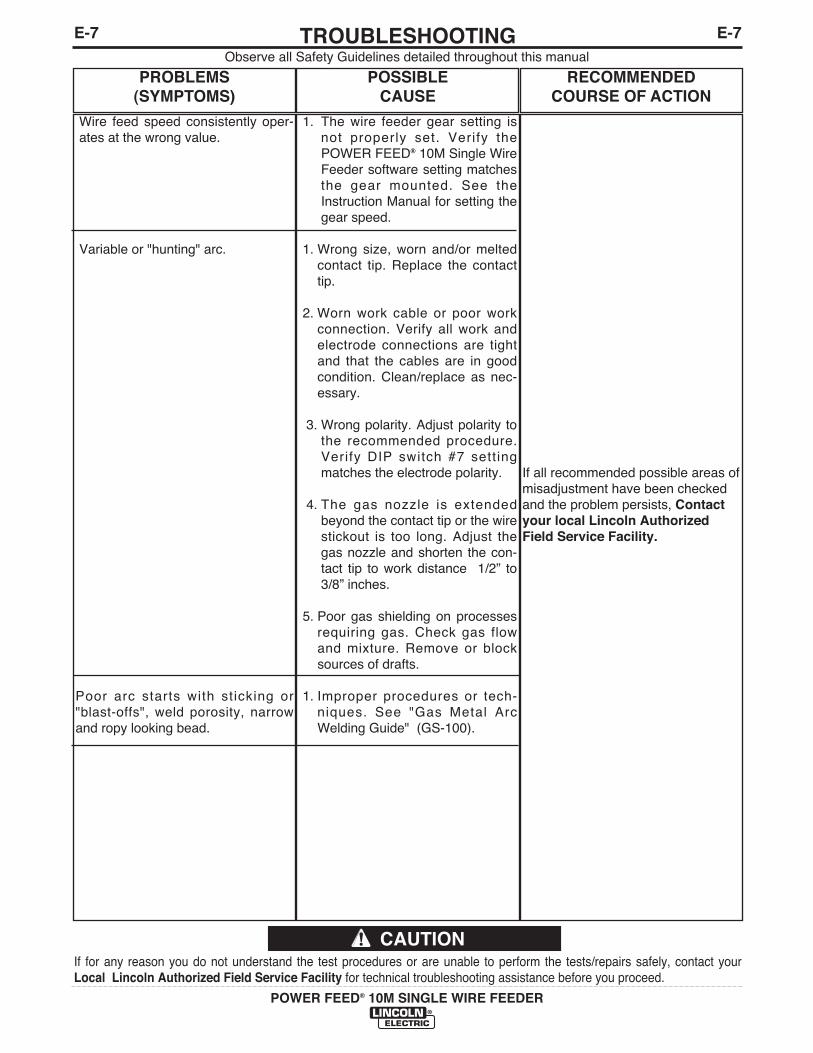
E-7TROUBLESHOOTINGE-7
POWER FEED® 10M SINGLE WIRE FEEDER
Observe all Safety Guidelines detailed throughout this manual
If for any reason you do not understand the test procedures or are unable to perform the tests/repairs safely, contact yourLocal Lincoln Authorized Field Service Facility for technical troubleshooting assistance before you proceed.
CAUTION
PROBLEMS(SYMPTOMS)
POSSIBLE CAUSE
RECOMMENDEDCOURSE OF ACTION
Wire feed speed consistently oper-ates at the wrong value.
Variable or "hunting" arc.
Poor arc starts with sticking or"blast-offs", weld porosity, narrowand ropy looking bead.
1. The wire feeder gear setting isnot properly set. Verify thePOWER FEED® 10M Single WireFeeder software setting matchesthe gear mounted. See theInstruction Manual for setting thegear speed.
1. Wrong size, worn and/or meltedcontact tip. Replace the contacttip.
2. Worn work cable or poor workconnection. Verify all work andelectrode connections are tightand that the cables are in goodcondition. Clean/replace as nec-essary.
3. Wrong polarity. Adjust polarity tothe recommended procedure.Verify DIP switch #7 settingmatches the electrode polarity.
4. The gas nozzle is extendedbeyond the contact tip or the wirestickout is too long. Adjust thegas nozzle and shorten the con-tact tip to work distance 1/2” to3/8” inches.
5. Poor gas shielding on processesrequiring gas. Check gas flowand mixture. Remove or blocksources of drafts.
1. Improper procedures or tech-niques. See "Gas Metal ArcWelding Guide" (GS-100).
If all recommended possible areas ofmisadjustment have been checkedand the problem persists, Contactyour local Lincoln AuthorizedField Service Facility.
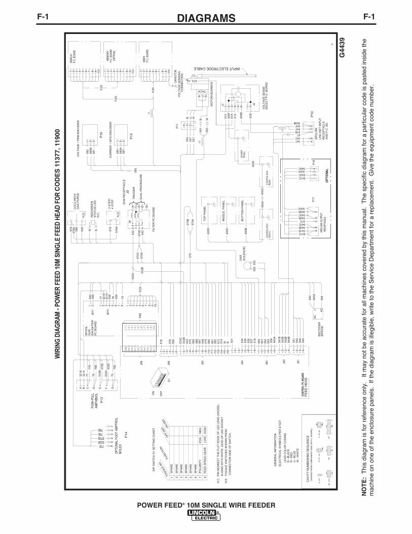
F-1DIAGRAMSF-1
POWER FEED® 10M SINGLE WIRE FEEDER
NO
TE
:T
his
diag
ram
is fo
r re
fere
nce
only
. It
may
not
be
accu
rate
for
all m
achi
nes
cove
red
by th
is m
anua
l. T
he s
peci
fic d
iagr
am fo
r a
part
icul
ar c
ode
is p
aste
d in
side
the
mac
hine
on
one
of th
e en
clos
ure
pane
ls.
If th
e di
agra
m is
ille
gibl
e, w
rite
to th
e S
ervi
ce D
epar
tmen
t for
a r
epla
cem
ent.
Giv
e th
e eq
uipm
ent c
ode
num
ber.
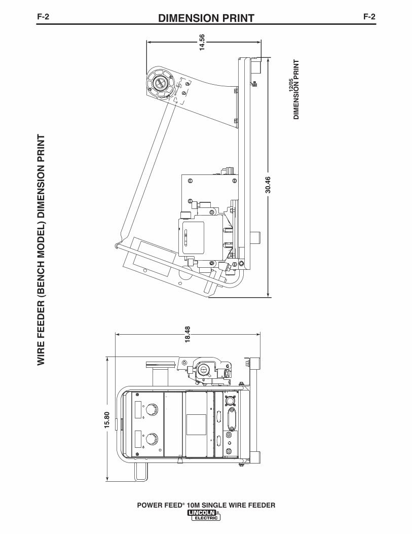
F-2DIMENSION PRINTF-2
POWER FEED® 10M SINGLE WIRE FEEDER
15.8
0
18.4
8
30.4
6
DIM
EN
SIO
N P
RIN
T12
/05
14.5
6
WIR
E F
EE
DE
R (
BE
NC
H M
OD
EL
) D
IME
NS
ION
PR
INT

NOTES
POWER FEED® 10M SINGLE WIRE FEEDER

NOTES
POWER FEED® 10M SINGLE WIRE FEEDER

WARNING
AVISO DEPRECAUCION
ATTENTION
WARNUNG
ATENÇÃO
Spanish
French
German
Portuguese
Japanese
Chinese
Korean
Arabic
READ AND UNDERSTAND THE MANUFACTURER’S INSTRUCTION FOR THIS EQUIPMENT AND THE CONSUMABLES TO BEUSED AND FOLLOW YOUR EMPLOYER’S SAFETY PRACTICES.
SE RECOMIENDA LEER Y ENTENDER LAS INSTRUCCIONES DEL FABRICANTE PARA EL USO DE ESTE EQUIPO Y LOSCONSUMIBLES QUE VA A UTILIZAR, SIGA LAS MEDIDAS DE SEGURIDAD DE SU SUPERVISOR.
LISEZ ET COMPRENEZ LES INSTRUCTIONS DU FABRICANT EN CE QUI REGARDE CET EQUIPMENT ET LES PRODUITS AETRE EMPLOYES ET SUIVEZ LES PROCEDURES DE SECURITE DE VOTRE EMPLOYEUR.
LESEN SIE UND BEFOLGEN SIE DIE BETRIEBSANLEITUNG DER ANLAGE UND DEN ELEKTRODENEINSATZ DES HER-STELLERS. DIE UNFALLVERHÜTUNGSVORSCHRIFTEN DES ARBEITGEBERS SIND EBENFALLS ZU BEACHTEN.
� Do not touch electrically live parts orelectrode with skin or wet clothing.
� Insulate yourself from work andground.
� No toque las partes o los electrodosbajo carga con la piel o ropa moja-da.
� Aislese del trabajo y de la tierra.
� Ne laissez ni la peau ni des vête-ments mouillés entrer en contactavec des pièces sous tension.
� Isolez-vous du travail et de la terre.
� Berühren Sie keine stromführendenTeile oder Elektroden mit IhremKörper oder feuchter Kleidung!
� Isolieren Sie sich von denElektroden und dem Erdboden!
� Não toque partes elétricas e elec-trodos com a pele ou roupa molha-da.
� Isole-se da peça e terra.
� Keep flammable materials away.
� Mantenga el material combustiblefuera del área de trabajo.
� Gardez à l’écart de tout matérielinflammable.
� Entfernen Sie brennbarres Material!
� Mantenha inflamáveis bem guarda-dos.
� Wear eye, ear and body protection.
� Protéjase los ojos, los oídos y elcuerpo.
� Protégez vos yeux, vos oreilles etvotre corps.
� Tragen Sie Augen-, Ohren- und Kör-perschutz!
� Use proteção para a vista, ouvido ecorpo.

WARNING
AVISO DEPRECAUCION
ATTENTION
WARNUNG
ATENÇÃO
Spanish
French
German
Portuguese
Japanese
Chinese
Korean
Arabic
LEIA E COMPREENDA AS INSTRUÇÕES DO FABRICANTE PARA ESTE EQUIPAMENTO E AS PARTES DE USO, E SIGA ASPRÁTICAS DE SEGURANÇA DO EMPREGADOR.
� Keep your head out of fumes.� Use ventilation or exhaust to
remove fumes from breathing zone.
� Los humos fuera de la zona de res-piración.
� Mantenga la cabeza fuera de loshumos. Utilice ventilación oaspiración para gases.
� Gardez la tête à l’écart des fumées.� Utilisez un ventilateur ou un aspira-
teur pour ôter les fumées des zonesde travail.
� Vermeiden Sie das Einatmen vonSchweibrauch!
� Sorgen Sie für gute Be- undEntlüftung des Arbeitsplatzes!
� Mantenha seu rosto da fumaça.� Use ventilação e exhaustão para
remover fumo da zona respiratória.
� Turn power off before servicing.
� Desconectar el cable de ali-mentación de poder de la máquinaantes de iniciar cualquier servicio.
� Débranchez le courant avant l’entre-tien.
� Strom vor Wartungsarbeitenabschalten! (Netzstrom völlig öff-nen; Maschine anhalten!)
� Não opere com as tampas removidas.� Desligue a corrente antes de fazer
serviço.� Não toque as partes elétricas nuas.
� Do not operate with panel open orguards off.
� No operar con panel abierto oguardas quitadas.
� N’opérez pas avec les panneauxouverts ou avec les dispositifs deprotection enlevés.
� Anlage nie ohne Schutzgehäuseoder Innenschutzverkleidung inBetrieb setzen!
� Mantenha-se afastado das partesmoventes.
� Não opere com os paineis abertosou guardas removidas.

• Sales and Service through Subsidiaries and Distributors Worldwide •
Cleveland, Ohio 44117-1199 U.S.A. TEL: 216.481.8100 FAX: 216.486.1751 WEB SITE: www.lincolnelectric.com
• World's Leader in Welding and Cutting Products •