operator's manual - taylor company · operator's manual models 702, 741 & 772 soft...
TRANSCRIPT
OPERATOR'SMANUAL
Models 702, 741 & 772Soft Serve Freezers
Original Operating Instructions
028759-M6/97 (Original Publication)
(Updated 7/1/15)
Complete this page for quick reference when service is required:
Taylor Distributor:
Address:
Phone:
Service:
Parts:
Date of Installation:
Information found on the data label:
Model Number:
Serial Number:
Electrical Specs: Voltage Cycle
Phase
Maximum Fuse Size: A
Minimum Wire Ampacity: A
E 1997 Carrier Commercial Refrigeration, Inc.028759-MAny unauthorized reproduction, disclosure, or distribution of copies by any person of any portion of this work may bea violation of Copyright Law of the United States of America and other countries, could result in the awarding of StatutoryDamages of up to $250,000 (17 USC 504) for infringement, and may result in further civil and criminal penalties.All rights reserved.
Taylor Companya division of Carrier Commercial Refrigeration, Inc.750 N. Blackhawk Blvd.Rockton, IL 61072

Models 702/741/772 Table of Contents
Table of Contents
Section 1 To the Installer 1. . . . . . . . . . . . . . . . . . . . . . . . . . . . . . . . . . . . . . . . . . . .
Installer Safety 1. . . . . . . . . . . . . . . . . . . . . . . . . . . . . . . . . . . . . . . . . . . . . . . . . . . . . . . .
Site Preparation 1. . . . . . . . . . . . . . . . . . . . . . . . . . . . . . . . . . . . . . . . . . . . . . . . . . . . . . .
Air Cooled Units 2. . . . . . . . . . . . . . . . . . . . . . . . . . . . . . . . . . . . . . . . . . . . . . . . . . . . . . .
Water Connections (Water Cooled Units Only) 2. . . . . . . . . . . . . . . . . . . . . . . . . . . .
Electrical Connections 2. . . . . . . . . . . . . . . . . . . . . . . . . . . . . . . . . . . . . . . . . . . . . . . . .
Check Out 3. . . . . . . . . . . . . . . . . . . . . . . . . . . . . . . . . . . . . . . . . . . . . . . . . . . . . . . . . . . .
Refrigerant 4. . . . . . . . . . . . . . . . . . . . . . . . . . . . . . . . . . . . . . . . . . . . . . . . . . . . . . . . . . .
Section 2 To the Operator 5. . . . . . . . . . . . . . . . . . . . . . . . . . . . . . . . . . . . . . . . . . .
Section 3 Safety 6. . . . . . . . . . . . . . . . . . . . . . . . . . . . . . . . . . . . . . . . . . . . . . . . . . . .
Section 4 Operator Parts Identification 8. . . . . . . . . . . . . . . . . . . . . . . . . . . . . . .
Model 702 8. . . . . . . . . . . . . . . . . . . . . . . . . . . . . . . . . . . . . . . . . . . . . . . . . . . . . . . . . . . .
Model 702 Door Assembly 9. . . . . . . . . . . . . . . . . . . . . . . . . . . . . . . . . . . . . . . . . . . . .
Model 741 10. . . . . . . . . . . . . . . . . . . . . . . . . . . . . . . . . . . . . . . . . . . . . . . . . . . . . . . . . . . .
Model 772 11. . . . . . . . . . . . . . . . . . . . . . . . . . . . . . . . . . . . . . . . . . . . . . . . . . . . . . . . . . . .
Models 741 & 772 Door Assembly 12. . . . . . . . . . . . . . . . . . . . . . . . . . . . . . . . . . . . . . .
Section 5 Important: To the Operator 13. . . . . . . . . . . . . . . . . . . . . . . . . . . . . . . . .
Indicator Light “Mix Low” 13. . . . . . . . . . . . . . . . . . . . . . . . . . . . . . . . . . . . . . . . . . . . . . .
Symbol Definitions 13. . . . . . . . . . . . . . . . . . . . . . . . . . . . . . . . . . . . . . . . . . . . . . . . . . . .
Control Switch 13. . . . . . . . . . . . . . . . . . . . . . . . . . . . . . . . . . . . . . . . . . . . . . . . . . . . . . . .
Reset Button 13. . . . . . . . . . . . . . . . . . . . . . . . . . . . . . . . . . . . . . . . . . . . . . . . . . . . . . . . .
Thermistor Control 14. . . . . . . . . . . . . . . . . . . . . . . . . . . . . . . . . . . . . . . . . . . . . . . . . . . .
Separate Hopper Refrigeration System (SHR) 14. . . . . . . . . . . . . . . . . . . . . . . . . . . .
Section 6 Operating Procedures 15. . . . . . . . . . . . . . . . . . . . . . . . . . . . . . . . . . . . .
Assembly 15. . . . . . . . . . . . . . . . . . . . . . . . . . . . . . . . . . . . . . . . . . . . . . . . . . . . . . . . . . . .
Sanitizing 18. . . . . . . . . . . . . . . . . . . . . . . . . . . . . . . . . . . . . . . . . . . . . . . . . . . . . . . . . . . .
Priming 19. . . . . . . . . . . . . . . . . . . . . . . . . . . . . . . . . . . . . . . . . . . . . . . . . . . . . . . . . . . . . .
Closing Procedure 20. . . . . . . . . . . . . . . . . . . . . . . . . . . . . . . . . . . . . . . . . . . . . . . . . . . .
Draining Product From the Freezing Cylinder 20. . . . . . . . . . . . . . . . . . . . . . . . . . . . .

Table of Contents Models 702/741/772
Table of Contents - Page 2
Rinsing 20. . . . . . . . . . . . . . . . . . . . . . . . . . . . . . . . . . . . . . . . . . . . . . . . . . . . . . . . . . . . . .
Cleaning 20. . . . . . . . . . . . . . . . . . . . . . . . . . . . . . . . . . . . . . . . . . . . . . . . . . . . . . . . . . . . .
Disassembly 21. . . . . . . . . . . . . . . . . . . . . . . . . . . . . . . . . . . . . . . . . . . . . . . . . . . . . . . . . .
Brush Cleaning 21. . . . . . . . . . . . . . . . . . . . . . . . . . . . . . . . . . . . . . . . . . . . . . . . . . . . . . .
Section 7 Important: Operator Checklist 22. . . . . . . . . . . . . . . . . . . . . . . . . . . . . .
During Cleaning and Sanitizing 22. . . . . . . . . . . . . . . . . . . . . . . . . . . . . . . . . . . . . . . . .
Troubleshooting Bacterial Count 22. . . . . . . . . . . . . . . . . . . . . . . . . . . . . . . . . . . . . . . .
Regular Maintenance Checks 22. . . . . . . . . . . . . . . . . . . . . . . . . . . . . . . . . . . . . . . . . . .
Winter Storage 23. . . . . . . . . . . . . . . . . . . . . . . . . . . . . . . . . . . . . . . . . . . . . . . . . . . . . . . .
Section 8 Troubleshooting Guide 24. . . . . . . . . . . . . . . . . . . . . . . . . . . . . . . . . . . .
Section 9 Parts Replacement Schedule 27. . . . . . . . . . . . . . . . . . . . . . . . . . . . . . .
Section 10 Limited Warranty on Equipment 28. . . . . . . . . . . . . . . . . . . . . . . . . . . .
Section 11 Limited Warranty on Parts 30. . . . . . . . . . . . . . . . . . . . . . . . . . . . . . . . .
Note: Continuing research results in steady improvements; therefore, informationin this manual is subject to change without notice.
Note: Only instructions originating from the factory or its authorized translationrepresentative(s) are considered to be the original set of instructions.
E 1997 Carrier Commercial Refrigeration, Inc. (Original Publication)(Updated July, 2015)028759-MAny unauthorized reproduction, disclosure, or distribution of copies by any person of any portion of this workmay be a violation of Copyright Law of the United States of America and other countries, could result in theawarding of Statutory Damages of up to $250,000 (17 USC 504) for infringement, and may result in furthercivil and criminal penalties.All rights reserved.
Taylor Companya division of Carrier Commercial Refrigeration, Inc.750 N. Blackhawk Blvd.Rockton, IL 61072
1Models 702/741/772 To the Installer
131206
Section 1 To the Installer
The following information has been included in themanual as safety and regulatory guidelines. Forcomplete installation instructions, please see theInstallation Checklist.
Installer Safety
In all areas of the world, equipment should beinstalled in accordance with existing local codes.Please contact your local authorities if you have anyquestions.
Care should be taken to ensure that all basic safetypractices are followed during the installation andservicing activities related to the installation andservice of Taylor equipment.
S Only authorized Taylor service personnelshould perform installation and repairs on theequipment.
S Authorized service personnel should consultOSHA Standard 29CFRI910.147 or theapplicable code of the local area for theindustry standards on lockout/tagoutprocedures before beginning any installationor repairs.
S Authorized service personnel must ensurethat the proper PPE is available and wornwhen required during installation and service.
S Authorized service personnelmust remove allmetal jewelry, rings, and watches beforeworking on electrical equipment.
The main power supply(s) to the machinemust be disconnected prior to performing any repairs.Failure to follow this instruction may result in personalinjury or death from electrical shock or hazardousmoving parts as well as poor performance or damageto the equipment.
Note: All repairs must be performed by anauthorized Taylor Service Technician.
This unit has many sharp edges that cancause severe injuries.
Site Preparation
Review the area where the unit will be installed beforeuncrating the unit. Make sure that all possible hazardsto the user and the equipment have been addressed.
For Indoor UseOnly: This unit is designed to operateindoors, under normal ambient temperatures of70_-75_F (21_-24_C). The freezer has successfullyperformed in high ambient temperatures of104_(40_C) at reduced capacities.
This unit must NOT be installed in an areawhere a water jet or hose can be used. NEVER use awater jet or hose to rinse or clean the unit. Failure tofollow this instruction may result in electrocution.
This unit must be installed on a level surfaceto avoid the hazard of tipping. Extreme care should betaken in moving this equipment for any reason. Two ormore people are required to safely move this unit.Failure to comply may result in personal injury orequipment damage.
Uncrate the unit and inspect it for damage. Report anydamage to your Taylor Distributor.
This piece of equipment is made in the USA and hasUSA sizes of hardware. All metric conversions areapproximate and vary in size.
2To the Installer Models 702/741/772
110616
Air Cooled UnitsDO NOT obstruct air intake and discharge openings:
The model 702 requires a minimum of 6” (152 mm) ofclearance around both sides of the freezer. Install thedeflector on the right sideof theunit andplace thebackof the unit against the wall to prevent recirculation ofwarm air. The models 741 and 772 require a minimumof 3” (76 mm) of clearance around all sides. Install thedeflector provided. Failure to allow adequateclearance can reduce the refrigeration capacity of thefreezers and possibly cause permanent damage to thecompressors.
Water Connections(Water Cooled Units Only)An adequate cold water supply must be provided witha hand shut-off valve. On the underside rear of thebase pan, two 3/8” I.P.S. (for single head units) or two1/2” I.P.S. (for double head units) water connectionsfor inlet and outlet have been provided for easyhook-up. 1/2” inside diameter water lines should beconnected to the machine. (Flexible lines arerecommended, if local codes permit.) Depending onlocal water conditions, it may be advisable to install awater strainer to prevent foreign substances fromclogging the automatic water valve. There will be onlyone water “in” and one water “out” connection for bothsingle head and double head units. DO NOT install ahand shut-off valve on the water “out” line! Watershould always flow in this order: First, through theautomatic water valve; second, through thecondenser; and third, through the outlet fitting to anopen trap drain.
A back flow prevention device is requiredon the incoming water connection side. Pleaserefer to the applicable National, State, and local codesfor determining the proper configuration.
Electrical Connections
In the United States, this equipment is intended to beinstalled in accordance with the National ElectricalCode (NEC), ANSI/NFPA70-1987. Thepurpose of theNEC code is the practical safeguardingof persons andproperty from hazards arising from the use ofelectricity. This code contains provisions considerednecessary for safety. In all other areas of the world,equipment should be installed in accordance with theexisting local codes. Please contact your localauthorities.
FOLLOW YOUR LOCAL ELECTRICAL CODES!
Each freezer requires one power supply for each datalabel. Check thedata label(s) on the freezer for branchcircuit overcurrent protection or fuse, wire ampacity,and electrical specifications. Refer to the wiringdiagram provided inside of the electrical box for properpower connections.
CAUTION: THIS EQUIPMENT MUST BEPROPERLY GROUNDED! FAILURE TO DO SOCAN RESULT IN SEVERE PERSONAL INJURYFROM ELECTRICAL SHOCK!
This unit is provided with an equipotentialgrounding lug that is to be properly attached to the rearof the frameby the authorized installer. The installationlocation is marked by the equipotential bondingsymbol (5021 of IEC 60417-1) on both the removablepanel and the equipment’s frame.

3Models 702/741/772 To the Installer
130304
S Stationary appliances which are not equippedwith a power cord anda plugor another deviceto disconnect the appliance from the powersource must have an all-pole disconnectingdevice with a contact gap of at least 3 mminstalled in the external installation.
S Appliances that are permanently connected tofixed wiring and for which leakage currentsmay exceed 10 mA, particularly whendisconnected, not used for long periods, orduring initial installation, shall have protectivedevices such as a GFI to protect against theleakage of current and be installed byauthorized personnel to the local codes.
S Supply cords used with this unit shall beoil-resistant, sheathed, flexible cable, notlighter than ordinary polychloroprene or otherequivalent synthetic elastomer-sheathed cord(Code designation 60245 IEC 57) installedwith the proper cord anchorage to relieveconductors from strain, including twisting atthe terminals, and protect the insulation of theconductors from abrasion.
If the supply cord is damaged, it must bereplaced by the manufacturer, its serviceagent, or similarly qualified person, in order toavoid a hazard.
Check OutOnce the unit is installed, it is advisable to check thefollowing controls and mechanical operations of thefreezer and make any necessary adjustments. Ifapplicable, repeat these checks for the secondfreezing cylinder on double head units.
Controls
Place the control switch in the “AUTO” position. Themain refrigeration system will operate (compressor,beater motor, and the condenser fan). The dial lightand the mix low indicator will be lit.
Figure 1
If the freezer is water cooled, the automatic watervalvewill begin to open and cold water will flow into thecondenser. This will remove heat from the refrigerant.As thewater flows into the open trap drain, it should bewarm to the touch. Place the control switch in the“OFF” position.
Beater Rotation
Beater rotation must be clockwise as viewedlooking into the freezing cylinder.
Note: The following procedures must beperformed by an authorized Taylor servicetechnician.
To correct rotation on a three-phase unit, interchangeany two incoming power supply lines at the freezermain terminal block only.
To correct rotation on a single-phase unit, exchangeleads inside the beater motor. (Follow the diagramprinted on the motor.)
Electrical connections are made directly to theterminal block provided in themain control box locatedbehind the upper left side panel for theModel 702, andbehind the service panel for the Model 741 and 772.
4To the Installer Models 702/741/772
130813
Refrigerant
In consideration of our environment, Taylorproudly uses only earth friendly HFC refrigerants. TheHFC refrigerant used in this unit is R404A. Thisrefrigerant is generally considered non-toxic andnon-flammable, with an Ozone Depleting Potential(ODP) of zero (0).
However, any gas under pressure is potentiallyhazardous and must be handled with caution.
NEVER fill any refrigerant cylinder completely withliquid. Filling the cylinder to approximately 80% willallow for normal expansion.
Use only R404A refrigerant that conforms tothe AHRI standard 700 specification. The use of anyother refrigerant may expose users and operators tounexpected safety hazards.
Refrigerant liquid sprayed onto the skin maycause serious damage to tissue. Keep eyes and skinprotected. If refrigerant burns should occur, flushimmediately with cold water. If burns are severe, applyice packs and contact a physician immediately.
Taylor reminds technicians to be cautious ofgovernment laws regarding refrigerant recovery,recycling, and reclaiming systems. If you have anyquestions regarding these laws, please contact thefactory Service Department.
WARNING: R404A refrigerant used inconjunction with polyolester oils is extremely moistureabsorbent. When opening a refrigeration system, themaximum time the system is openmust not exceed 15minutes. Cap all open tubing to prevent humid air orwater from being absorbed by the oil.

5Models 702/741/772 To the Operator
131206
Section 2 To the Operator
The freezer you have purchased has been carefullyengineered andmanufactured to give you dependableoperation. The Taylor freezer, when properly operatedand cared for, will produceaconsistent quality product.Like all mechanical products, this machine will requirecleaningandmaintenance. Aminimumamount of careand attention is necessary if the operating proceduresoutlined in this manual are followed closely.
This Operator’s Manual should be read beforeoperating or performing any maintenance on yourequipment.
Your Taylor freezer will NOT eventually compensateand correct for any errors during the set-up or fillingoperations. Thus, the initial assembly and primingprocedures are of extreme importance. It is stronglyrecommended that all personnel responsible for theequipment’s operation review these procedures inorder to beproperly trainedand tomakesure that thereis no confusion.
In the event that you should require technicalassistance, please contact your local authorizedTaylor Distributor.
Note: Your Taylor warranty is valid only if the parts areauthorized Taylor parts, purchased from the localauthorized Taylor Distributor, and only if all requiredservice work is provided by an authorized Taylorservice technician. Taylor reserves the right to denywarranty claims on units or parts if non- Taylorapproved parts or incorrect refrigerant were installedin the unit, system modifications were performedbeyond factory recommendations, or it is determinedthat the failure was caused by abuse, misuse, neglect,or failure to follow all operating instructions. For fulldetails of your Taylor Warranty, please see the LimitedWarranty section in this manual.
Note: Constant research results in steadyimprovements; therefore, information in thismanual is subject to change without notice.
If the crossed out wheeled bin symbol isaffixed to this product, it signifies that this product iscompliant with the EUDirective as well as other similarlegislation in effect after August 13, 2005. Therefore,it must be collected separately after its use iscompleted, and cannot be disposed as unsortedmunicipal waste.
The user is responsible for returning the product to theappropriate collection facility, as specified by your localcode.
For additional information regarding applicable locallaws, please contact the municipal facility and/or localdistributor.
Compressor Warranty Disclaimer
The refrigeration compressor(s) on this unit arewarranted for the term stated in the Limited Warrantysection in this manual. However, due to the MontrealProtocol and the U.S. Clean Air Act Amendments of1990, many new refrigerants are being tested anddeveloped, thus seeking their way into the serviceindustry. Some of these new refrigerants are beingadvertised as drop- in replacements for numerousapplications. It should be noted that in the event ofordinary service to this unit’s refrigeration system,only the refrigerant specified on the affixed datalabel should be used. The unauthorized use ofalternate refrigerants will void your Taylor compressorwarranty. It is the unit owner’s responsibility to makethis fact known to any technician he employs.
It should also be noted that Taylor does not warrant therefrigerant used in its equipment. For example, if therefrigerant is lost during the course of ordinary serviceto this machine, Taylor has no obligation to eithersupply or provide its replacement either at billable orunbillable terms. Taylor does have the obligation torecommend a suitable replacement if the originalrefrigerant is banned, obsoleted, or no longer availableduring the five year warranty of the compressor.
The Taylor Company will continue to monitor theindustry and test new alternates as they are beingdeveloped. Should a new alternate prove, through ourtesting, that it would be accepted as a drop-inreplacement, then the above disclaimer wouldbecome null and void. To find out the current status ofan alternate refrigerant as it relates to yourcompressor warranty, call the local Taylor Distributoror the Taylor Factory. Be prepared to provide theModel/Serial Number of the unit in question.

6Safety Models 702/741/772
130304
Section 3 Safety
We, at Taylor Company, are concerned about thesafety of the operatorwhen heor she comes in contactwith the freezer and its parts. Taylor has gone toextreme efforts to design and manufacture built- insafety features to protect both the operator and theservice technician. As an example, warning labelshave been attached to the freezer to further point outsafety precautions.
IMPORTANT - Failure to adhere to thefollowing safety precautions may result in severepersonal injury or death. Failure to comply withthese warnings may damage the machine and itscomponents. Component damage will result inpart replacement expense and service repairexpense.
DONOT operate the freezer without readingthis Operator Manual. Failure to follow this instructionmay result in equipment damage, poor freezerperformance, health hazards, or personal injury.
This appliance is to be used only by trainedpersonnel. It is not intended for use by children orpeople with reduced physical, sensory, or mentalcapabilities, or lack of experience and knowledge,unless given supervision or instruction concerning theuse of the appliance by a person responsible for theirsafety. Children should be supervised to ensure thatthey do not play with the appliance.
This unit is provided with an equipotentialgrounding lug that is to be properly attached to the rearof the frameby the authorized installer. The installationlocation is marked by the equipotential bondingsymbol (5021 of IEC 60417-1) on both the removablepanel and the equipment’s frame.
DO NOT use a water jet to clean or rinse thefreezer. Failure to follow these instructions may resultin serious electrical shock.
S DO NOT operate the freezer unless it isproperly grounded.
S DO NOT operate freezer with larger fusesthan specified on the freezer data label.
S All repairs must be performed by anauthorized Taylor service technician.
S Themain power supplies to the machinemustbe disconnected prior to performing anyrepairs.
S CordConnectedUnits: Only Taylor authorizedservice technicians may install a plug on thisunit.
S Stationary appliances which are not equippedwith a power cord anda plugor another deviceto disconnect the appliance from the powersource must have an all-pole disconnectingdevice with a contact gap of at least 3 mminstalled in the external installation.
S Appliances that are permanently connected tofixed wiring and for which leakage currentsmay exceed 10 mA, particularly whendisconnected, not used for long periods, orduring initial installation, shall have protectivedevices such as a GFI to protect against theleakage of current and be installed byauthorized personnel to the local codes.
S Supply cords used with this unit shall beoil-resistant, sheathed, flexible cable, notlighter than ordinary polychloroprene or otherequivalent synthetic elastomer-sheathed cord(Code designation 60245 IEC 57) installedwith the proper cord anchorage to relieveconductors from strain, including twisting, atthe terminals and protect the insulation of theconductors from abrasion.
If the supply cord is damaged, it must bereplaced by the manufacturer, its serviceagent, or similarly qualified person, in order toavoid a hazard.
Failure to follow these instructions may result inelectrocution. Contact your local authorized TaylorDistributor for service.

7Models 702/741/772 Safety
131010
S DONOT allow untrained personnel to operatethis machine.
S DONOT operate the freezer unless all servicepanels and access doors are restrained withscrews.
S DO NOT remove any internal operating parts(examples: freezer door, beater, scraperblades, etc.) unless all control switches are inthe OFF position.
Failure to follow these instructionsmay result in severepersonal injury to fingers or hands from hazardousmoving parts.
This unit has many sharp edges that cancause severe injuries.
S DO NOT put objects or fingers in the doorspout. This may contaminate the product andcause severe personal injury from bladecontact.
S USE EXTREME CAUTION when removingthe beater asssembly. The scraper blades arevery sharp.
This freezermust beplaced ona level surface.Failure to comply may result in personal injury orequipment damage.
Access to the service area of the unit isrestricted to persons having knowledge and practicalexperience with the appliance, in particular as far assafety and hygiene are concerned.
Cleaning and sanitizing schedules aregoverned by your state or local regulatory agenciesand must be followed accordingly. Please refer to thecleaning section of this manual for the properprocedure to clean this unit.
This machine is designed to maintain producttemperature under 41_F (5_C). Any product beingadded to this machine must be below 41_F (5_C).Failure to follow this instruction may result in healthhazards and poor freezer performance.
DO NOT run the unit without product. Failure to followthis instruction can result in damage to the unit.
DO NOT obstruct air intake and discharge openings:
Counter Model:Minimum of 6” (152 mm) of air spaceon both sides. Install the deflector on the right side ofthe unit and place the back of the unit against the wallto prevent recirculation of warm air.
ConsoleModels:Minimum of 3” (76mm) of air spacearound all sides. Install the deflector to preventrecirculation of warm air.
Failure to follow these instructions may cause poorfreezer performance and damage to the machine.
For Indoor UseOnly: This unit is designed to operateindoors, under normal ambient temperatures of 70_ -75_F (21_ - 24_C). The freezer has successfullyperformed in high ambient temperatures of 104_F(40_C) at reduced capacities.
NOISE LEVEL: Airborne noise emission does notexceed 78 dB(A) when measured at a distance of 1.0meter from the surface of the machine and at a heightof 1.6 meters from the floor.
8Operator Parts Identification Models 702/741/772
140527
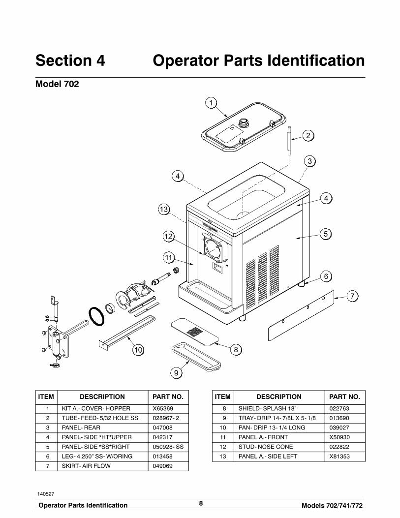
Section 4 Operator Parts IdentificationModel 702
ITEM DESCRIPTION PART NO.
1 KIT A.- COVER- HOPPER X65369
2 TUBE- FEED- 5/32 HOLE SS 028967- 2
3 PANEL- REAR 047008
4 PANEL- SIDE *HT*UPPER 042317
5 PANEL- SIDE *SS*RIGHT 050928- SS
6 LEG- 4.250” SS-W/ORING 013458
7 SKIRT- AIR FLOW 049069
ITEM DESCRIPTION PART NO.
8 SHIELD- SPLASH 18” 022763
9 TRAY- DRIP 14- 7/8L X 5- 1/8 013690
10 PAN- DRIP 13- 1/4 LONG 039027
11 PANEL A.- FRONT X50930
12 STUD- NOSE CONE 022822
13 PANEL A.- SIDE LEFT X81353
9Models 702/741/772 Operator Parts Identification
141027
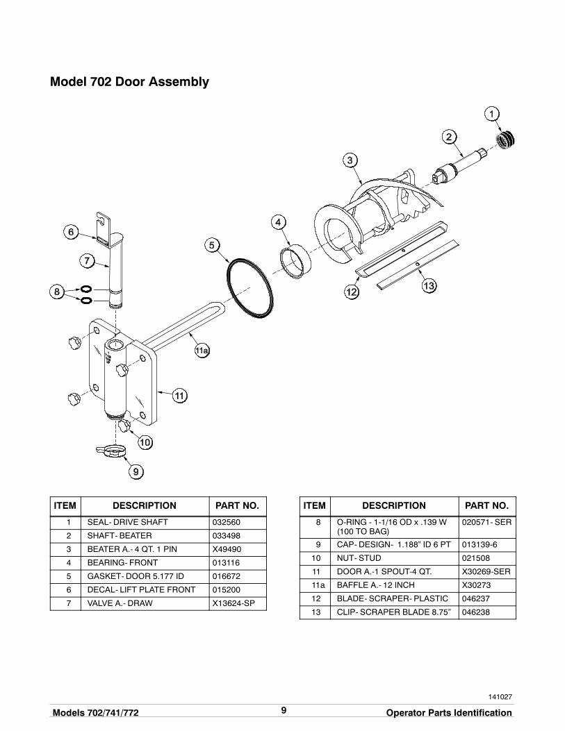
Model 702 Door Assembly
ITEM DESCRIPTION PART NO.
1 SEAL- DRIVE SHAFT 032560
2 SHAFT- BEATER 033498
3 BEATER A.- 4 QT. 1 PIN X49490
4 BEARING- FRONT 013116
5 GASKET- DOOR 5.177 ID 016672
6 DECAL- LIFT PLATE FRONT 015200
7 VALVE A.- DRAW X13624-SP
ITEM DESCRIPTION PART NO.
8 O-RING - 1-1/16 OD x .139 W(100 TO BAG)
020571- SER
9 CAP- DESIGN- 1.188” ID 6 PT 013139-6
10 NUT- STUD 021508
11 DOOR A.-1 SPOUT-4 QT. X30269-SER
11a BAFFLE A.- 12 INCH X30273
12 BLADE- SCRAPER- PLASTIC 046237
13 CLIP- SCRAPER BLADE 8.75” 046238

10Operator Parts Identification Models 702/741/772
140409
Model 741
ITEM DESCRIPTION PART NO.
1 COVER A.- HOPPER- STD X38458- SER
1a KNOB- MIX COVER 025429
2 GASKET- HOPPER COVER 038375
3 PAN- DRIP 11- 5/8 LONG 027503
4 TUBE- FEED- SS- 3/16 028967- 3
5 PANEL- REAR 013637
6 LOUVER- SIDE- TOP 051192
7 PANEL- SIDE UPPER R. 028707
8 PANEL A.- SIDE LOWER X24397- SER
9 ADAPTOR A.- CASTER X18915
ITEM DESCRIPTION PART NO.
10 CASTER- SWV 5/8 STEM 018794
11 CASTER- 4” SWV 5/8 STEMW/BRAKE
034081
12 PANEL- SERVICE 013638
13 TRAY- DRIP 14- 7/8L X 5- 1/8 013690
14 SHIELD- SPLASH 15”L 022763
15 PANEL A.- FRONT *FOOTPEDAL
X14238- SP
16 STUD- NOSE CONE 022822
17 PANEL- SIDE UPPER L. 028706

11Models 702/741/772 Operator Parts Identification
140409
Model 772
ITEM DESCRIPTION PART NO.
1 KIT A.- COVER- HOPPER X65369
2 PAN- DRIP 11- 5/8 LONG 027503
3 PANEL- UPPER SIDE L. 028700
4 TUBE- FEED- SS- 3/16 028967- 3
5 PANEL- REAR 017563
6 LOUVER- SIDE- TOP 051191
7 PANEL- UPPER SIDE R. 028701
8 PANEL A.- SIDE RIGHT X44855- SER
9 ADAPTOR A.- CASTER X18915
ITEM DESCRIPTION PART NO.
10 CASTER- 4” SWV 5/8 STEM 018794
11 CASTER- 4” SWV 5/8 STEMW/BRAKE
034081
12 PANEL- SERVICE 046584
13 SHIELD- SPLASH 037041
14 TRAY- DRIP 014533
15 PANEL A.- SIDE LEFT X44853- SER
16 PANEL A.- FRONT X51264
17 STUD- NOSE CONE 022822

12Operator Parts Identification Models 702/741/772
141027
Models 741 & 772 Door Assembly
ITEM DESCRIPTION PART NO.
1 SEAL- DRIVE SHAFT 032560
2 SHAFT- BEATER 033498
3 BEATER A.- 7 QT. 1 PIN X46233
4 BEARING- FRONT 013116
5 GASKET- DOOR 5.177 ID 016672
6 DECAL- LIFT PLATE FRONT 015200
7 VALVE A.- DRAW X13624-SP
ITEM DESCRIPTION PART NO.
8 O-RING 1- 1/16 OD X .139 W(100 TO BAG)
020571- SER
9 CAP- DESIGN- 1.188” ID 6 PT 013139-6
10 NUT- STUD 021508
11 DOOR A.- 1 SPOUT 7 QT. X30272-SER
11a BAFFLE A.- 19 INCH X30274
12 BLADE- SCRAPER- PLASTIC 046237
13 CLIP- SCRAPER BLADE 8.75” 046238

13Models 702/741/772 Important: To the Operator
Section 5 Important: To the Operator
Indicator Light “Mix Low”
The Models 702, 741, and 772 are equipped with a“MIX LOW” light located on the front of the machine.When the light begins to flash, it indicates that the mixhopper has a lowsupply ofmix. At this time, thehoppershould be filledwithmix. If youneglect to addmixwhenthe light begins to flash, eventual damage to thebeater, blades, drive shaft, and freezer door mayoccur.
Figure 2
Symbol Definitions
The following chart identifies the symbol definitionsused on the operator switches.
= The “WASH” keypad.
= The “OFF” keypad.
= The “ON/AUTO” keypad.
Control SwitchThe center position is “OFF”. The right position is“AUTO”, which activates the beater motor and therefrigeration system. The left position is “WASH”which activates the beater motor only.
Figure 3
Reset ButtonOn a Model 702, the reset button is located under theleft upper side panel. On the Model 772 and theModel741, the reset button is located on the lower frontpanel.
The reset button protects the beater motor from anoverload condition. If an overload occurs, the resetmechanism will trip. To properly reset the freezer,place the control switch in the “OFF” position. Pressthe reset button firmly. Place the control switch in the“WASH” position and observe the freezer’sperformance. Once satisfied, place the control switchback in the “AUTO” position.
Figure 4

14Important: To the Operator Models 702/741/772
080324
Thermistor ControlTheviscosity (thickness) of theproduct is controlled bya temperature sensing device called the thermistor. Toachieve a thicker product, turn the control clockwise,and turn the control counterclockwise to achieve athinner product. Allow the refrigeration system to cycleon and off 2 or 3 times before an accurate consistencycan be evaluated.
Separate Hopper RefrigerationSystem (SHR)
“Standby”The Separate Hopper Refrigeration System (SHR)and the Cylinder Temperature Retention System(CTR) are standard features. This feature is referredto as “STANDBY”. The SHR incorporates the use of aseparate small refrigeration system to maintain themix temperature in the hopper to below 40_F. (4.4_C.)This assures bacteria control. The CTRworks with theSHR to maintain a good quality product. During long“No Sale” periods, it becomes necessary to warm theproduct in the freezing cylinder to approximately 35_F.to 40_F. (1.7_C. to 4.4_C.) to prevent overbeating andproduct breakdown.
ALWAYS FOLLOW LOCAL HEALTH CODES.
Cleaning and sanitizing schedules are governedby federal, state, or local regulatory agencies, andmust be followed accordingly. If the unit has a“Standby mode”, it must not be used in lieu ofproper cleaning and sanitizing procedures andfrequencies set forth by the ruling healthauthority.
CLEANING AND SANITIZING MUST BEPERFORMED DAILY.
IMPORTANT: Make sure your hands aresanitized before performing these instructions:
To activate SHR and CTR, place the air tube (endwithout the hole) into the mix inlet hole.
Place the control switch in the “AUTO” position, andturn the STANDBY switch to the “ON” position. Theunit will operate as a refrigerator for product in thehopper and freezing cylinder.
To remove the unit from the “STANDBY” mode, placethe control switch in the “AUTO” position, and turn thestandby switch to the “OFF” position. The unit willresume the normal operating mode.
When the unit cycles off, remove the hopper cover,and place the feed tube in its original position.
Replace the hopper cover.
15Models 702/741/772 Operating Procedures
Section 6 Operating Procedures
The Model 702 has been selected to show you thepictured step-by-step operating procedures for allmodels contained in this manual. These models, forpractical purposes of operation, are the same.
They all store 20 quarts (18.9 liters) of mix in thehopper. The mix then flows by gravity through a mixfeed tube down into the freezing cylinder.
Locate your model number below to determine thecharacteristics of your freezer:
702: (1) 4 quart (3.8 liter) freezing cylinder.741: (1) 7 quart (6.6 liter) freezing cylinder.772: (2) 7 quart (6.6 liter) freezing cylinders.We begin our instructions at the point where we enterthe store in the morning and find the partsdisassembled and laid out to air dry from the previousnight’s cleaning.The following procedures will show you how toassemble the parts into the freezer, sanitize them, andprime the freezer with freshmix in preparation to serveyour first portion.
If you are disassembling the machine for the first timeor need information to get to this starting point in ourinstructions, turn to page 21, “Disassembly” and startthere.
Assembly
MAKE SURE THE CONTROL SWITCH ISIN THE “OFF” POSITION TO ELIMINATE THECHANCE OF MOVING PARTS.
Note: When lubricating parts, use an approved foodgrade lubricant (example: Taylor Lube).
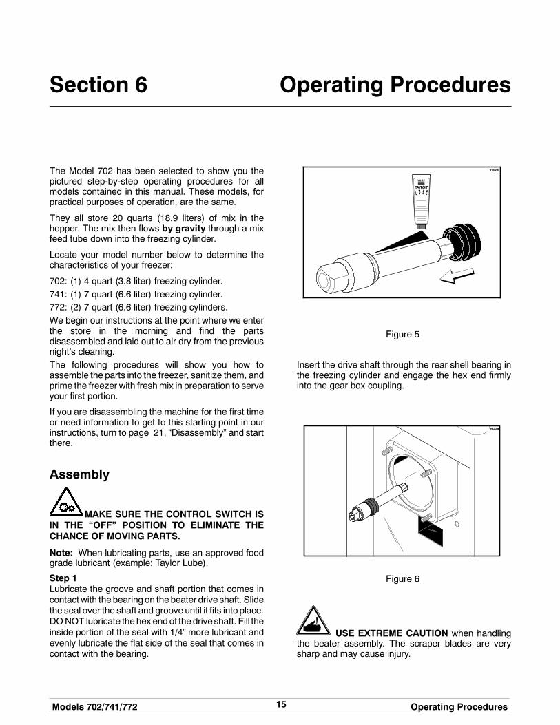
Step 1Lubricate the groove and shaft portion that comes incontact with thebearingon thebeater drive shaft. Slidethe seal over the shaft and groove until it fits into place.DONOT lubricate thehex endof thedriveshaft. Fill theinside portion of the seal with 1/4” more lubricant andevenly lubricate the flat side of the seal that comes incontact with the bearing.
Figure 5
Insert the drive shaft through the rear shell bearing inthe freezing cylinder and engage the hex end firmlyinto the gear box coupling.
Figure 6
USE EXTREME CAUTION when handlingthe beater assembly. The scraper blades are verysharp and may cause injury.
16Operating Procedures Models 702/741/772
150701
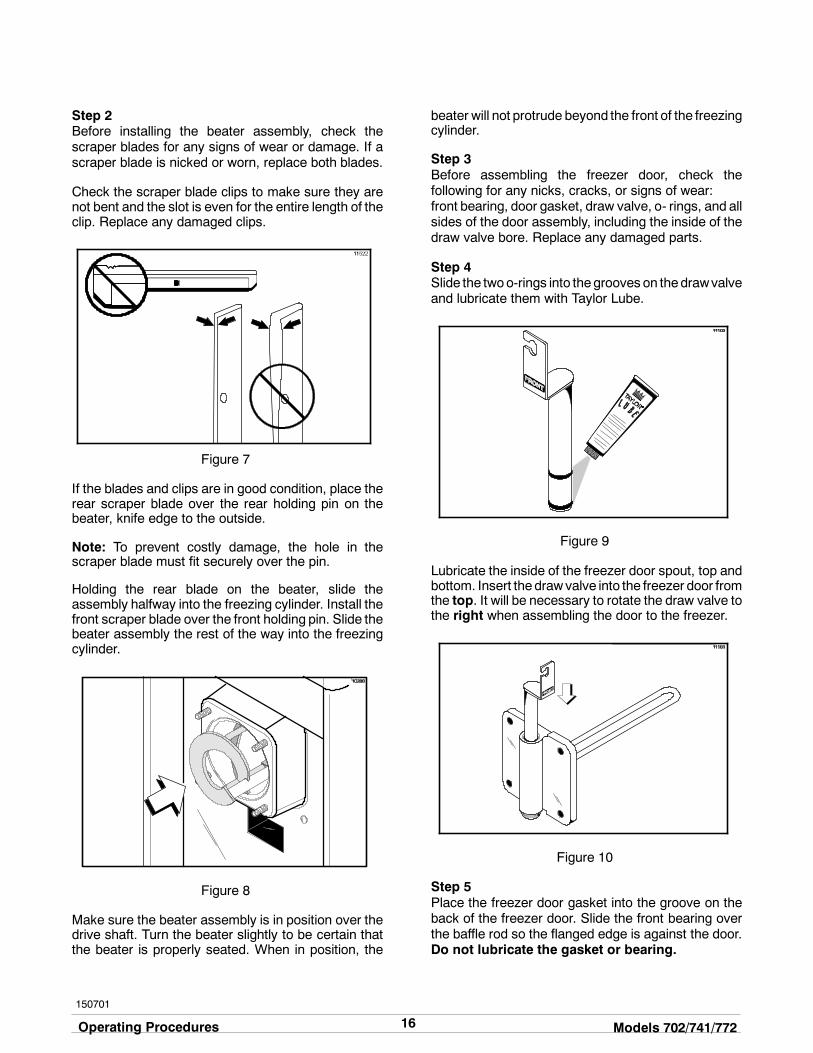
Step 2Before installing the beater assembly, check thescraper blades for any signs of wear or damage. If ascraper blade is nicked or worn, replace both blades.
Check the scraper blade clips to make sure they arenot bent and the slot is even for the entire length of theclip. Replace any damaged clips.
Figure 7
If the blades and clips are in good condition, place therear scraper blade over the rear holding pin on thebeater, knife edge to the outside.
Note: To prevent costly damage, the hole in thescraper blade must fit securely over the pin.
Holding the rear blade on the beater, slide theassembly halfway into the freezing cylinder. Install thefront scraper blade over the front holding pin. Slide thebeater assembly the rest of the way into the freezingcylinder.
Figure 8
Make sure the beater assembly is in position over thedrive shaft. Turn the beater slightly to be certain thatthe beater is properly seated. When in position, the
beater will not protrude beyond the front of the freezingcylinder.
Step 3Before assembling the freezer door, check thefollowing for any nicks, cracks, or signs of wear:front bearing, door gasket, draw valve, o- rings, and allsides of the door assembly, including the inside of thedraw valve bore. Replace any damaged parts.
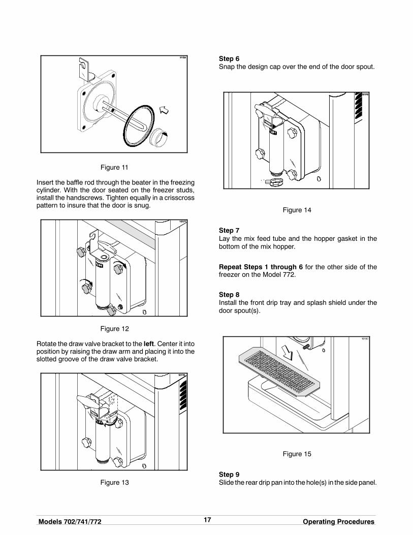
Step 4Slide the twoo-rings into thegrooves on thedrawvalveand lubricate them with Taylor Lube.
Figure 9
Lubricate the inside of the freezer door spout, top andbottom. Insert the drawvalve into the freezer door fromthe top. It will be necessary to rotate the draw valve tothe right when assembling the door to the freezer.
Figure 10
Step 5Place the freezer door gasket into the groove on theback of the freezer door. Slide the front bearing overthe baffle rod so the flanged edge is against the door.Do not lubricate the gasket or bearing.
17Models 702/741/772 Operating Procedures
Figure 11
Insert the baffle rod through the beater in the freezingcylinder. With the door seated on the freezer studs,install the handscrews. Tighten equally in a crisscrosspattern to insure that the door is snug.
Figure 12
Rotate the draw valve bracket to the left. Center it intoposition by raising the draw arm and placing it into theslotted groove of the draw valve bracket.
Figure 13
Step 6Snap the design cap over the end of the door spout.
Figure 14
Step 7Lay the mix feed tube and the hopper gasket in thebottom of the mix hopper.
Repeat Steps 1 through 6 for the other side of thefreezer on the Model 772.
Step 8Install the front drip tray and splash shield under thedoor spout(s).
Figure 15
Step 9Slide the rear drip pan into thehole(s) in the sidepanel.

18Operating Procedures Models 702/741/772
150701
Sanitizing
Step 1Prepare a pail of an approved 100 PPM sanitizingsolution (examples: 2- 1/2 gal. [9.5 liters] of Kay- 5Ror 2 gal. [7.6 liters] of Stera- SheenR). USE WARMWATER AND FOLLOW THE MANUFACTURER’SSPECIFICATIONS.
Step 2Pour the sanitizing solution into the hopper and allowit to flow into the freezing cylinder.
Figure 16
Step 3While the solution is flowing into the freezing cylinder,brush clean thehopper.While cleaning themixhopper,take particular care in brushing the mix level sensingprobe on the rear wall of the hopper, the mix inlet hole,the hopper gasket, and the mix feed tube.
Figure 17
Step 4Place the control switch in the “WASH” position. Thiswill cause the sanitizing solution in the freezingcylinder to agitate. Allow the solution to agitate for fiveminutes.
Figure 18
Step 5Place an empty pail beneath the door spout and raisethe draw arm. Draw off all the sanitizing solution.
Figure 19
Step 6When the sanitizer stops flowing from the door spout,lower the draw arm and place the control switch in the“OFF” position.
IMPORTANT! The unit must NOT be placed in AUTOuntil all sanitizing solution has been removed from thefreezing cylinder and proper priming procedures havebeen completed. Failure to follow this instruction mayresult in damage to the freezing cylinder.
Note: You have just sanitized the freezer;therefore, be sure your hands are sanitized beforecontinuing these instructions.
19Models 702/741/772 Operating Procedures
140718
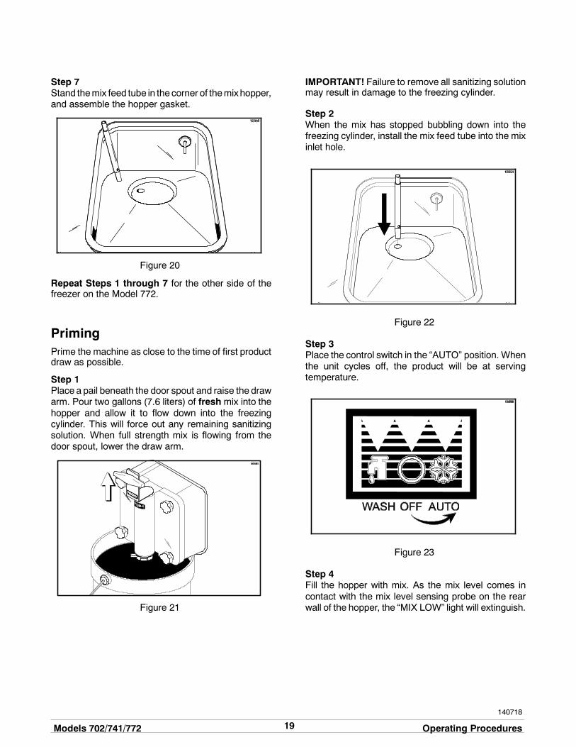
Step 7Stand themix feed tube in the corner of themixhopper,and assemble the hopper gasket.
Figure 20
Repeat Steps 1 through 7 for the other side of thefreezer on the Model 772.
PrimingPrime the machine as close to the time of first productdraw as possible.
Step 1Place a pail beneath the door spout and raise the drawarm. Pour two gallons (7.6 liters) of freshmix into thehopper and allow it to flow down into the freezingcylinder. This will force out any remaining sanitizingsolution. When full strength mix is flowing from thedoor spout, lower the draw arm.
Figure 21
IMPORTANT! Failure to remove all sanitizing solutionmay result in damage to the freezing cylinder.
Step 2When the mix has stopped bubbling down into thefreezing cylinder, install the mix feed tube into the mixinlet hole.
Figure 22
Step 3Place the control switch in the “AUTO” position. Whenthe unit cycles off, the product will be at servingtemperature.
Figure 23
Step 4Fill the hopper with mix. As the mix level comes incontact with the mix level sensing probe on the rearwall of the hopper, the “MIX LOW” light will extinguish.

20Operating Procedures Models 702/741/772
140718
Step 5Place the mix hopper cover in position.
Figure 24
Repeat Steps 1 through 5 for the other side of thefreezer on the Model 772.
Closing ProcedureTo disassemble your unit, the following items will beneeded:
S Two cleaning pailsS Sanitized stainless steel rerun can with lidS Necessary brushes (provided with freezer)S CleanerS Single service towels
Draining Product From theFreezing CylinderStep 1Place the control switch in the “OFF” position.
Step 2Remove the hopper cover, the hopper gasket, and themix feed tube. Take theseparts to the sink for cleaning.
Step 3If local health codes permit the use of rerun, placea sanitized, NSF approved stainless steel reruncontainer beneath the door spout. Place the controlswitch in the “WASH” position and raise the draw arm.When all product stops flowing from the door spout,lower the draw arm and place the control switch in the“OFF” position. Place a sanitized lid on the reruncontainer and place it in the walk- in cooler.(Note: For additional information regarding the properuse of rerun, see item 5 on page 22.)
Note: If local health codesDONOTpermit theuseof rerun, the productmust bediscarded. Follow theinstructions in the previous step, except drain theproduct into a pail and properly discard the mix.
Repeat these steps for the second freezing cylinderon the Model 772.
ALWAYS FOLLOW LOCAL HEALTH CODES.
RinsingStep 1Pour two gallons (7.6 liters) of cool, clean water intothe mix hopper. With the brushes provided, scrub themix hopper, the mix inlet hole, and the mix levelsensing probe.
Step 2With a pail beneath the door spout, place the controlswitch in the “WASH” position and raise the draw arm.Drain all the rinse water from the freezing cylinder.When the rinse water stops flowing from the doorspout, lower the draw arm and place the control switchin the “OFF” position.
Repeat this procedure until the rinse water beingdrawn from the freezing cylinder is clear.
Repeat these steps for the second freezing cylinderon the Model 772.
CleaningStep 1Prepare a pail of an approved 100 PPM sanitizingsolution (examples: 2- 1/2 gal. [9.5 liters] of Kay- 5Ror 2 gal. [7.6 liters] of Stera- SheenR). USE WARMWATER AND FOLLOW THE MANUFACTURER’SSPECIFICATIONS.
Step 2Pour the cleaning solution into the hopper and allow itto flow into the freezing cylinder.
Step 3While the solution is flowing into the freezing cylinder,brush clean the mix hopper, the mix inlet hole, and themix level sensing probe.
Step 4Place the control switch in the “WASH” position. Thiswill cause the cleaning solution in the freezing cylinderto agitate.
21Models 702/741/772 Operating Procedures
080324
Step 5Place an empty pail beneath the door spout and raisethe draw arm. Draw off all the cleaning solution. Whenthe solution stops flowing from the door spout, lowerthe draw arm and place the control switch in the “OFF”position.
Repeat Steps 1 through 5 for the second freezingcylinder on the Model 772.
DisassemblyNote: Failure to remove parts, brush clean and thenair dry these parts, will result in damage to the relatedparts.
Step 1
BE SURE THE CONTROL SWITCH IS INTHE “OFF” POSITION TO ELIMINATE THECHANCE OF MOVING PARTS.
Step 2Remove the handscrews, the freezer door, the gasket,the front bearing, the beater, the scraper blade(s), andthe drive shaft from the freezing cylinder. Take theseparts to the sink for cleaning.
Step 3Remove the rear drip pan from the front panel.
Note: If the drip pan is filled with an excessive amountof mix, it is an indication that the drive shaft seal shouldbe replaced or was improperly lubricated.
Repeat these steps for the second freezing cylinderon the Model 772.
Step 4Remove the front drip tray and the splash shield.
Brush CleaningStep 1Prepare a sink with an approved cleaning solution (ex-amples: Kay-5R or Stera- SheenR). USE WARMWATER AND FOLLOW THE MANUFACTURER’SSPECIFICATIONS
If an approved cleaner other than Kay-5R or Stera-SheenR is used, dilute it according to the label instruc-tions. IMPORTANT: Follow the label directions. TooSTRONG of a solution can cause parts damage. TooMILD of a solution will not provide adequate cleaning.
Make sure all brushes provided with the freezer areavailable for brush cleaning.
Step 2Remove the seal(s) from the drive shaft(s).
Step 3From the freezer door(s) remove:
S the gasket(s)S the front bearing(s)S the design cap(s)S the draw valve(s)
Remove all o-rings.
Note: To remove o-rings, usea single service towel tograsp theo-ring. Apply pressure in an upwarddirectionuntil the o-ring pops out of its groove. With the otherhand, push the top of the o-ring forward. It will roll outof the groove and can be easily removed. If there ismore than one o-ring to be removed, always removethe rear o-ring first. This will allow the o-ring to slideover the forward rings without falling into the opengrooves.
Step 4Thoroughly brush clean all disassembled parts in thecleaning solution,making sure all lubricant andmix filmis removed. Take particular care to brush clean thedraw valve core in the freezer door(s). Place all thecleaned parts on a clean dry surface to air dryovernight.
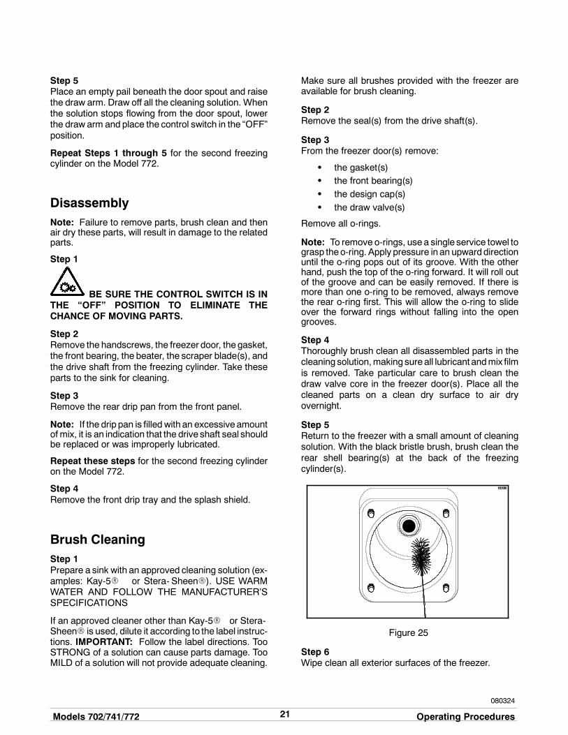
Step 5Return to the freezer with a small amount of cleaningsolution. With the black bristle brush, brush clean therear shell bearing(s) at the back of the freezingcylinder(s).
Figure 25
Step 6Wipe clean all exterior surfaces of the freezer.
22Important: Operator Checklist Models 702/741/772
110616
Section 7 Important: Operator Checklist
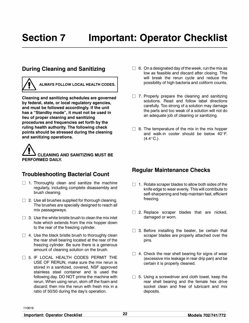
During Cleaning and Sanitizing
ALWAYS FOLLOW LOCAL HEALTH CODES.
Cleaning and sanitizing schedules are governedby federal, state, or local regulatory agencies,and must be followed accordingly. If the unithas a “Standby mode”, it must not be used inlieu of proper cleaning and sanitizingprocedures and frequencies set forth by theruling health authority. The following checkpoints should be stressed during the cleaningand sanitizing operations.
CLEANING AND SANITIZING MUST BEPERFORMED DAILY.
Troubleshooting Bacterial Countj 1. Thoroughly clean and sanitize the machine
regularly, including complete disassembly andbrush cleaning.
j 2. Use all brushes supplied for thorough cleaning.The brushes are specially designed to reach allmix passageways.
j 3. Use the white bristle brush to clean the mix inlethole which extends from the mix hopper downto the rear of the freezing cylinder.
j 4. Use the black bristle brush to thoroughly cleanthe rear shell bearing located at the rear of thefreezing cylinder. Be sure there is a generousamount of cleaning solution on the brush.
j 5. IF LOCAL HEALTH CODES PERMIT THEUSE OF RERUN, make sure the mix rerun isstored in a sanitized, covered, NSF approvedstainless steel container and is used thefollowing day. DO NOT prime the machine withrerun. When using rerun, skim off the foam anddiscard; then mix the rerun with fresh mix in aratio of 50/50 during the day’s operation.
j 6. On a designated day of theweek, run themix aslow as feasible and discard after closing. Thiswill break the rerun cycle and reduce thepossibility of high bacteria and coliform counts.
j 7. Properly prepare the cleaning and sanitizingsolutions. Read and follow label directionscarefully. Too strong of a solution may damagethe parts and too weak of a solution will not doan adequate job of cleaning or sanitizing.
j 8. The temperature of the mix in the mix hopperand walk-in cooler should be below 40_F.(4.4_C.).
Regular Maintenance Checks
j 1. Rotate scraper blades to allow both sides of theknife edge to wear evenly. This will contribute toself-sharpening and help maintain fast, efficientfreezing.
j 2. Replace scraper blades that are nicked,damaged or worn.
j 3. Before installing the beater, be certain thatscraper blades are properly attached over thepins.
j 4. Check the rear shell bearing for signs of wear(excessive mix leakage in rear drip pan) and becertain it is properly cleaned.
j 5. Using a screwdriver and cloth towel, keep therear shell bearing and the female hex drivesocket clean and free of lubricant and mixdeposits.

23Models 702/741/772 Important: Operator Checklist
080324
j 6. Dispose of o-rings and seals if they are worn,torn, or fit too loosely, and replace with newones.
j 7. Follow all lubricating procedures as outlined in“Assembly”.
j 8. Check the condensers for accumulation of dirtand lint. Dirty condensers will reduce theefficiency and capacity of the machine.Condensers should be cleanedmonthly with asoft brush. Never use screwdrivers or othermetal probes to clean between the fins.Note: For machines equipped with an air filter,it will be necessary to vacuum clean the filterson a monthly schedule.
j 9. On water cooled units, check the water lines forkinks or leaks. Kinks can occur when themachine is moved back and forth for cleaningormaintenance purposes. Deteriorated orcracked water lines should be replaced only byan authorized Taylor technician.
Winter StorageIf the placeof business is to be closedduring thewintermonths, it is important to protect the freezer byfollowing certain precautions, particularly if thebuilding is subject to freezing conditions.
Disconnect the freezer from the main power source toprevent possible electrical damage.
On water cooled freezers, disconnect the watersupply. Relieve pressure on the spring in the watervalve. Use air pressure on the outlet side to blow outany water remaining in the condenser. This isextremely important. Failure to follow this proceduremay cause severe and costly damage to therefrigeration system.
Your local Taylor Distributor can perform this servicefor you.
Wrap detachable parts of the freezer such as thebeater, blades, drive shaft, and freezer door. Placethese parts in a protected, dry place. Rubber trimpartsand gaskets can be protected by wrapping them withmoisture-proof paper. All parts should be thoroughlycleaned of dried mix or lubrication which attract miceand other vermin.

24Troubleshooting Guide Models 702/741/772
Section 8 Troubleshooting Guide
PROBLEM PROBABLE CAUSE REMEDY PAGEREF.
1. No product beingdispensed with the drawvalve open and the controlswitch in AUTO.
a. The freezer door isinstalled upside down.
a. Install the door correctly. 16
b. There is a freeze-up in themix inlet hole.
b. Call service technician toadjust the hoppertemperature.
- -
c. The beater motor is out onreset.
c. Reset the freezer. 13
d. The beater is rotatingcounterclockwise.
d. Contact service technicianto correct the rotation toclockwise.
- -
e. The draw valve isconnected to the drawarm incorrectly.
e. The draw valve bracketmust be correctly attachedto the draw arm.
17
f. The circuit breaker is offor the fuse is blown.
f. Turn the breaker on orreplace the fuse.
- -
g. Inadequate mix in hopper. g. Fill the hopper with mix. 19
2. The product is too cold. a. The temperature control isset too cold.
a. Adjust the temperaturecontrol knob warmer.
14
b. The draw handle is notfully closed.
b. The draw handle must befully closed.
- -
3. The product appears toosoft.
a. The temperature control isset too warm.
a. Adjust the temperaturecontrol knob colder.
14
b. Insufficient air spacearound the unit. (A/C)
b. Allow for adequate air flowacross the condenser.
1
c. The scraper blade(s) areworn.
c. Replace scraper bladesregularly.
27
d. Dirty condenser. d. Clean regularly. 23
e. The mix is out of date. e. Use only fresh mix. - -
f. The beater is rotatingcounterclockwise.
f. Contact service technicianto correct rotation.
- -
g. Loss of water (W/C) g. Locate cause of waterloss and correct.
23
h. Product is broken downfrom overbeating.
h. Draw off some product toallow fresh product toenter the freezing cylinder.
- -

25Models 702/741/772 Troubleshooting Guide
150701
PROBLEM PROBABLE CAUSE REMEDY PAGEREF.
4. The mix in the hopper istoo cold.
a. The temperature is out ofadjustment.
a. Call service technician toadjust the hoppertemperature.
- -
5. The mix in the hopper istoo warm.
a. The temperature is out ofadjustment.
a. Call service technician toadjust the hoppertemperature.
- -
b. Hopper cover is not inposition.
b. Place the cover inposition.
20
c. The control switch is OFF. c. Place the control switch inAUTO.
19
d. Warm mix was placed inthe hopper.
d. Mix added to the hoppermust be below 40_F(4.4_C).
- -
6. The drive shaft is stuck inthe gear box coupling.
a. Rounded corners of driveshaft, coupling, or both.
a. Call service technician tocorrect the cause andreplace the necessarycomponents. Do notlubricate the end of thedrive shaft.
- -
7. The freezing cylinder wallsare scored.
a. The scraper blades and/orblade clips are damaged.
a. Replace the scraperblades and/or clips.
16
b. The front bearing ismissing or worn.
b. Install or replace the frontbearing.
16
c. Unit was placed in AUTObefore all sanitizingsolution was removedfrom freezing cylinder.
c. Place unit in AUTO onlyafter priming is completeand all sanitizing solutionis removed.
18
d. Broken pins on beaterassembly.
d. Repair or replace thebeater assembly. Be surethe scraper blades areproperly seated on pins.
16
e. The beater assembly isbent.
e. Call service technician torepair or replace thebeater and to correct thecause of insufficient mix inthe freezing cylinder.
- - -
8. Excessive mix leakageinto the rear drip pan.
a. Worn or missing driveshaft seal.
a. Replace regularly. 27
b. Inadequate lubrication ofdrive shaft seal.
b. Lubricate properly. 15
c. Worn rear shell bearing. c. Call service technician toreplace rear shell bearing.
- -

26Troubleshooting Guide Models 702/741/772
PROBLEM PROBABLE CAUSE REMEDY PAGEREF.
8. Excessive mix leakageinto the rear drip pan.(Cont’d.)
d. The drive shaft worksforward.
d. Call service technician tocorrect.
- -
e. The seal is installedinside-out on the driveshaft.
e. Install correctly. 15
f. The wrong type oflubricant is being used(example: petroleum baselubricant.).
f. Use the proper lubricant(example: Taylor Lube).
- -
9. Excessive mix leakagefrom the door spout.
a. Worn or missing drawvalve o-rings.
a. Replace regularly. 27
b. Inadequate lubrication ofthe draw valve o-rings.
b. Lubricate properly. 16
c. The wrong type oflubricant is being used(example: petroleum baselubricant.).
c. Use the proper lubricant(example: Taylor Lube).
- -
10. No freezer operation withthe control switch inAUTO.
a. The unit is unplugged. a. Plug into wall receptacle. - -
b. Circuit breaker off orblown fuse.
b. Turn circuit breaker on orreplace fuse.
- -
c. Beater motor out on reset. c. Reset the freezer. 13
11. Low overrun. a. Worn scraper blade(s). a. Replace regularly. 27
b. The mix feed assembly isnot installed.
b. Install in mix inlet hole. 19
c. Product is broken downfrom over-beating.
c. Draw off some product toallow fresh product toenter the freezing cylinder.
- -
12. The freezer door worksloose.
a. The freezer studs aredamaged.
a. Call service technician toreplace studs.
- -
b. The handscrews aredamaged.
b. Replace the handscrews. - -
c. There are enlarged holesin the freezer door.
c. Replace the door. - -
d. The handscrews are nottightened.
d. Tighten the handscrewsequally in a crisscrosspattern.
17
e. The beater assembly isrubbing the back of thedoor.
e. Call service technician tocorrect the problem.
- -
27Models 702/741/772 Parts Replacement Schedule
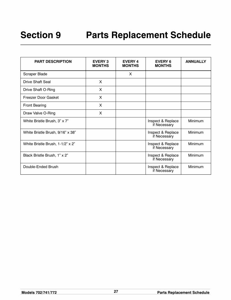
Section 9 Parts Replacement Schedule
PART DESCRIPTION EVERY 3MONTHS
EVERY 4MONTHS
EVERY 6MONTHS
ANNUALLY
Scraper Blade X
Drive Shaft Seal X
Drive Shaft O-Ring X
Freezer Door Gasket X
Front Bearing X
Draw Valve O-Ring X
White Bristle Brush, 3” x 7” Inspect & Replaceif Necessary
Minimum
White Bristle Brush, 9/16” x 38” Inspect & Replaceif Necessary
Minimum
White Bristle Brush, 1-1/2” x 2” Inspect & Replaceif Necessary
Minimum
Black Bristle Brush, 1” x 2” Inspect & Replaceif Necessary
Minimum
Double-Ended Brush Inspect & Replaceif Necessary
Minimum

28Limited Warranty on Equipment Models 702/741/772
131206
Section 10 Limited Warranty on Equipment
TAYLOR COMPANY LIMITED WARRANTY ON FREEZERS
Taylor Company, a division of Carrier Commercial Refrigeration, Inc. (“Taylor”) is pleased to provide this limitedwarranty on new Taylor-branded freezer equipment available from Taylor to the market generally (the “Product”)to the original purchaser only.
LIMITED WARRANTY
Taylor warrants the Product against failure due to defect in materials or workmanship under normal use andservice as follows. All warranty periods begin on the date of original Product installation. If a part fails due todefect during the applicable warranty period, Taylor, through an authorized Taylor distributor or service agency,will provide a new or re- manufactured part, at Taylor’s option, to replace the failed defective part at no charge forthe part. Except as otherwise stated herein, these are Taylor’s exclusive obligations under this limited warranty fora Product failure. This limited warranty is subject to all provisions, conditions, limitations and exclusions listedbelow and on the reverse (if any) of this document.
Product Part Limited Warranty Period
Soft ServeFrozen YogurtShakesSmoothies
Frozen BeverageBatch Desserts
Insulated shell assembly Five (5) years
Refrigeration compressor(except service valve)
Five (5) years
Beater motors Two (2) years
Beater drive gear Two (2) years
Printed circuit boards andSoftech controls beginningwith serial number H8024200
Two (2) years
Parts not otherwise listed inthis table or excluded below
One (1) year
LIMITED WARRANTY CONDITIONS
1. If the date of original installation of the Product cannot be verified, then the limited warranty period beginsninety (90) days from the date of Product manufacture (as indicated by the Product serial number). Proof ofpurchase may be required at time of service.
2. This limited warranty is valid only if the Product is installed and all required service work on the Product isperformed by an authorized Taylor distributor or service agency, and only if genuine, new Taylor parts areused.
3. Installation, use, care, and maintenance must be normal and in accordance with all instructions contained inthe Taylor Operator’s Manual.
4. Defective parts must be returned to the authorized Taylor distributor or service agency for credit.
5. The use of any refrigerant other than that specified on the Product’s data label will void this limited warranty.
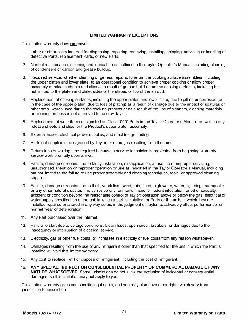
LIMITED WARRANTY EXCEPTIONS
This limited warranty does not cover:
1. Labor or other costs incurred for diagnosing, repairing, removing, installing, shipping, servicing or handling ofdefective parts, replacement parts, or new Products.
2. Normal maintenance, cleaning and lubrication as outlined in the Taylor Operator’s Manual, including cleaningof condensers.

29Models 702/741/772 Limited Warranty on Equipment
3. Replacement of wear items designated as Class “000” parts in the Taylor Operator’s Manual.
4. External hoses, electrical power supplies, and machine grounding.
5. Parts not supplied or designated by Taylor, or damages resulting from their use.
6. Return trips or waiting time required because a service technician is prevented from beginning warrantyservice work promptly upon arrival.
7. Failure, damage or repairs due to faulty installation, misapplication, abuse, no or improper servicing,unauthorized alteration or improper operation or use as indicated in the Taylor Operator’s Manual, includingbut not limited to the failure to use proper assembly and cleaning techniques, tools, or approved cleaningsupplies.
8. Failure, damage or repairs due to theft, vandalism, wind, rain, flood, high water, water, lightning, earthquakeor any other natural disaster, fire, corrosive environments, insect or rodent infestation, or other casualty,accident or condition beyond the reasonable control of Taylor; operation above or below the electrical orwater supply specification of the Product; or components repaired or altered in any way so as, in thejudgment of the Manufacturer, to adversely affect performance, or normal wear or deterioration.
9. Any Product purchased over the Internet.
10. Failure to start due to voltage conditions, blown fuses, open circuit breakers, or damages due to theinadequacy or interruption of electrical service.
11. Electricity or fuel costs, or increases in electricity or fuel costs from any reason whatsoever.
12. Damages resulting from the use of any refrigerant other than that specified on the Product’s data label willvoid this limited warranty.
13. Any cost to replace, refill or dispose of refrigerant, including the cost of refrigerant.
14. ANY SPECIAL, INDIRECT OR CONSEQUENTIAL PROPERTY OR COMMERCIAL DAMAGE OF ANYNATURE WHATSOEVER. Some jurisdictions do not allow the exclusion of incidental or consequentialdamages, so this limitation may not apply to you.
This limited warranty gives you specific legal rights, and you may also have other rights which vary fromjurisdiction to jurisdiction.
LIMITATION OF WARRANTY
THIS LIMITED WARRANTY IS EXCLUSIVE AND IS IN LIEU OF ALL OTHER WARRANTIES, CONDITIONSAND/OR REMEDIES UNDER THE LAW, INCLUDING ANY IMPLIED WARRANTIES OR CONDITIONS OFMERCHANTABILITY OR FITNESS FOR A PARTICULAR PURPOSE. THE ORIGINAL OWNER’S SOLEREMEDY WITH RESPECT TO ANY PRODUCTS SHALL BE REPAIR OR REPLACEMENT OF DEFECTIVECOMPONENTS UNDER THE TERMS OF THIS LIMITED WARRANTY. ALL RIGHTS TO CONSEQUENTIALOR INCIDENTAL DAMAGES (INCLUDING CLAIMS FOR LOST SALES, LOST PROFITS, PRODUCT LOSS,PROPERTY DAMAGES OR SERVICE EXPENSES) ARE EXPRESSLY EXCLUDED. THE EXPRESSWARRANTIES MADE IN THIS LIMITED WARRANTY MAY NOT BE ALTERED, ENLARGED, OR CHANGEDBY ANY DISTRIBUTOR, DEALER, OR OTHER PERSON, WHATSOEVER.
LEGAL REMEDIES
The owner must notify Taylor in writing, by certified or registered letter to the following address, of any defect orcomplaint with the Product, stating the defect or complaint and a specific request for repair, replacement, or othercorrection of the Product under warranty, mailed at least thirty (30) days before pursuing any legal rights orremedies.
Taylor Companya division of Carrier Commercial Refrigeration, Inc.
750 N. Blackhawk Blvd.Rockton, IL 61072, U.S.A.

30Limited Warranty on Parts Models 702/741/772
131206
Section 11 Limited Warranty on Parts
TAYLOR COMPANY LIMITED WARRANTY ON TAYLOR GENUINE PARTS
Taylor Company, a division of Carrier Commercial Refrigeration, Inc. (“Taylor”) is pleased to provide this limitedwarranty on new Taylor genuine replacement components and parts available from Taylor to the market generally(the “Parts”) to the original purchaser only.
LIMITED WARRANTY
Taylor warrants the Parts against failure due to defect in materials or workmanship under normal use and serviceas follows. All warranty periods begin on the date of original installation of the Part in the Taylor unit. If a Part failsdue to defect during the applicable warranty period, Taylor, through an authorized Taylor distributor or serviceagency, will provide a new or re- manufactured Part, at Taylor’s option, to replace the failed defective Part at nocharge for the Part. Except as otherwise stated herein, these are Taylor’s exclusive obligations under this limitedwarranty for a Part failure. This limited warranty is subject to all provisions, conditions, limitations and exclusionslisted below and on the reverse (if any) of this document.
Part’s Warranty Class Code or Part Limited Warranty Period
Class 103 Parts¹ Three (3) months
Class 212 Parts² Twelve (12) months
Class 512 Parts Twelve (12) months
Class 000 Parts No warranty
Taylor Part #072454 (Motor- 24VDC *C832/C842*) Four (4) years
LIMITED WARRANTY CONDITIONS
1. If the date of original installation of the Part cannot be otherwise verified, proof of purchase may be requiredat time of service.
2. This limited warranty is valid only if the Part is installed and all required service work in connection with thePart is performed by an authorized Taylor distributor or service agency.
3. The limited warranty applies only to Parts remaining in use by their original owner at their original installationlocation in the unit of original installation.
4. Installation, use, care, and maintenance must be normal and in accordance with all instructions contained inthe Taylor Operator’s Manual.
5. Defective Parts must be returned to the authorized Taylor distributor or service agency for credit.
6. This warranty is not intended to shorten the length of any warranty coverage provided pursuant to a separateTaylor Limited Warranty on freezer or grill equipment.
7. The use of any refrigerant other than that specified for the unit in which the Part is installed will void thislimited warranty.
1, 2 Except that Taylor Part #032129SER2 (Compressor-Air-230V SERV) and Taylor Part #075506SER1(Compressor-Air-115V 60HZ) shall have a limited warranty period of twelve (12) months when used in Taylorfreezer equipment and a limited warranty period of two (2) years when used in Taylor grill equipment.
31Models 702/741/772 Limited Warranty on Parts
LIMITED WARRANTY EXCEPTIONS
This limited warranty does not cover:
1. Labor or other costs incurred for diagnosing, repairing, removing, installing, shipping, servicing or handling ofdefective Parts, replacement Parts, or new Parts.
2. Normal maintenance, cleaning and lubrication as outlined in the Taylor Operator’s Manual, including cleaningof condensers or carbon and grease buildup.
3. Required service, whether cleaning or general repairs, to return the cooking surface assemblies, includingthe upper platen and lower plate, to an operational condition to achieve proper cooking or allow properassembly of release sheets and clips as a result of grease build-up on the cooking surfaces, including butnot limited to the platen and plate, sides of the shroud or top of the shroud.
4. Replacement of cooking surfaces, including the upper platen and lower plate, due to pitting or corrosion (orin the case of the upper platen, due to loss of plating) as a result of damage due to the impact of spatulas orother small wares used during the cooking process or as a result of the use of cleaners, cleaning materialsor cleaning processes not approved for use by Taylor.
5. Replacement of wear items designated as Class “000” Parts in the Taylor Operator’s Manual, as well as anyrelease sheets and clips for the Product’s upper platen assembly.
6. External hoses, electrical power supplies, and machine grounding.
7. Parts not supplied or designated by Taylor, or damages resulting from their use.
8. Return trips or waiting time required because a service technician is prevented from beginning warrantyservice work promptly upon arrival.
9. Failure, damage or repairs due to faulty installation, misapplication, abuse, no or improper servicing,unauthorized alteration or improper operation or use as indicated in the Taylor Operator’s Manual, includingbut not limited to the failure to use proper assembly and cleaning techniques, tools, or approved cleaningsupplies.
10. Failure, damage or repairs due to theft, vandalism, wind, rain, flood, high water, water, lightning, earthquakeor any other natural disaster, fire, corrosive environments, insect or rodent infestation, or other casualty,accident or condition beyond the reasonable control of Taylor; operation above or below the gas, electrical orwater supply specification of the unit in which a part is installed; or Parts or the units in which they areinstalled repaired or altered in any way so as, in the judgment of Taylor, to adversely affect performance, ornormal wear or deterioration.
11. Any Part purchased over the Internet.
12. Failure to start due to voltage conditions, blown fuses, open circuit breakers, or damages due to theinadequacy or interruption of electrical service.
13. Electricity, gas or other fuel costs, or increases in electricity or fuel costs from any reason whatsoever.
14. Damages resulting from the use of any refrigerant other than that specified for the unit in which the Part isinstalled will void this limited warranty.
15. Any cost to replace, refill or dispose of refrigerant, including the cost of refrigerant.
16. ANY SPECIAL, INDIRECT OR CONSEQUENTIAL PROPERTY OR COMMERCIAL DAMAGE OF ANYNATURE WHATSOEVER. Some jurisdictions do not allow the exclusion of incidental or consequentialdamages, so this limitation may not apply to you.
This limited warranty gives you specific legal rights, and you may also have other rights which vary fromjurisdiction to jurisdiction.

32Limited Warranty on Parts Models 702/741/772
LIMITATION OF WARRANTY
THIS LIMITED WARRANTY IS EXCLUSIVE AND IS IN LIEU OF ALL OTHER WARRANTIES, CONDITIONSAND/OR REMEDIES UNDER THE LAW, INCLUDING ANY IMPLIED WARRANTIES OR CONDITIONS OFMERCHANTABILITY OR FITNESS FOR A PARTICULAR PURPOSE. THE ORIGINAL OWNER’S SOLEREMEDY WITH RESPECT TO ANY PRODUCTS SHALL BE REPAIR OR REPLACEMENT OF DEFECTIVEPARTS UNDER THE TERMS OF THIS LIMITED WARRANTY. ALL RIGHTS TO CONSEQUENTIAL ORINCIDENTAL DAMAGES (INCLUDING CLAIMS FOR LOST SALES, LOST PROFITS, PRODUCT LOSS,PROPERTY DAMAGES OR SERVICE EXPENSES) ARE EXPRESSLY EXCLUDED. THE EXPRESSWARRANTIES MADE IN THIS LIMITED WARRANTY MAY NOT BE ALTERED, ENLARGED, OR CHANGEDBY ANY DISTRIBUTOR, DEALER, OR OTHER PERSON, WHATSOEVER.
LEGAL REMEDIES
The owner must notify Taylor in writing, by certified or registered letter to the following address, of any defect orcomplaint with the Part, stating the defect or complaint and a specific request for repair, replacement, or othercorrection of the Part under warranty, mailed at least thirty (30) days before pursuing any legal rights or remedies.
Taylor Companya division of Carrier Commercial Refrigeration, Inc.
750 N. Blackhawk Blvd.Rockton, IL 61072, U.S.A.