operator’smanual electric start capable gas …
TRANSCRIPT
769-17370 / 00 08/18
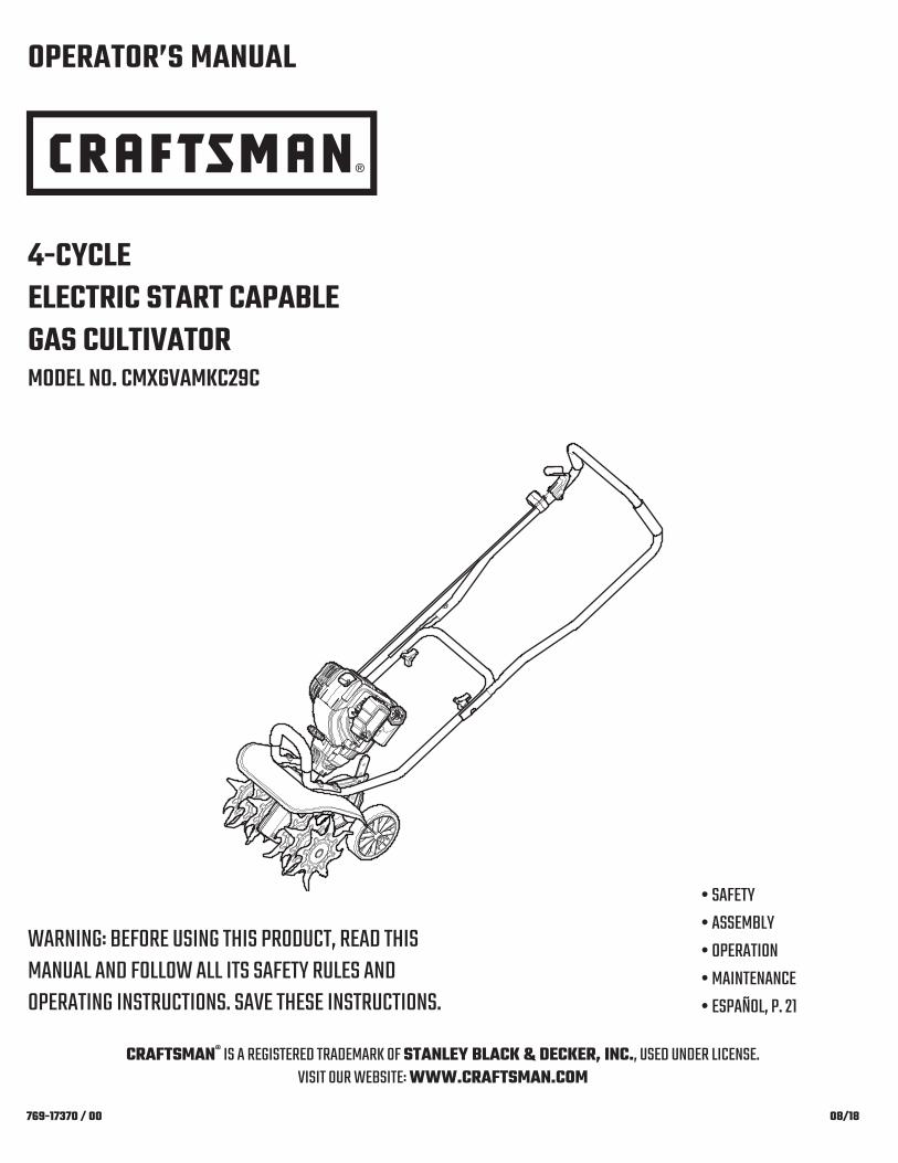
4-CYCLEELECTRIC START CAPABLEGAS CULTIVATORMODEL NO. CMXGVAMKC29C
OPERATOR’S MANUAL
• SAFETY• ASSEMBLY• OPERATION• MAINTENANCE• ESPAÑOL, P. 21
CRAFTSMAN® IS A REGISTERED TRADEMARK OF STANLEY BLACK & DECKER, INC., USED UNDER LICENSE.VISIT OUR WEBSITE: WWW.CRAFTSMAN.COM
WARNING: BEFORE USING THIS PRODUCT, READ THISMANUAL AND FOLLOW ALL ITS SAFETY RULES ANDOPERATING INSTRUCTIONS. SAVE THESE INSTRUCTIONS.

2
All information, illustrations, and specifications in this manual are basedon the latest product information available at the time of printing. Wereserve the right to make changes at any time without notice.The product may vary slightly from the illustrations contained in thismanual.
TABLE OF CONTENTS
Safety . . . . . . . . . . . . . . . . . . . . . . . . . . . . . . . . . . . . . . . . . . . . . . .2Know Your Unit . . . . . . . . . . . . . . . . . . . . . . . . . . . . . . . . . . . . . . . .6Specifications . . . . . . . . . . . . . . . . . . . . . . . . . . . . . . . . . . . . . . . . .6Assembly . . . . . . . . . . . . . . . . . . . . . . . . . . . . . . . . . . . . . . . . . . . . .7Oil and Fuel . . . . . . . . . . . . . . . . . . . . . . . . . . . . . . . . . . . . . . . . . . .8Starting and Stopping . . . . . . . . . . . . . . . . . . . . . . . . . . . . . . . . . .10Operation . . . . . . . . . . . . . . . . . . . . . . . . . . . . . . . . . . . . . . . . . . .12Maintenance . . . . . . . . . . . . . . . . . . . . . . . . . . . . . . . . . . . . . . . . .13Cleaning and Storage . . . . . . . . . . . . . . . . . . . . . . . . . . . . . . . . . .16Troubleshooting . . . . . . . . . . . . . . . . . . . . . . . . . . . . . . . . . . . . . .17Warranty . . . . . . . . . . . . . . . . . . . . . . . . . . . . . . . . . . . . . . . . . . . .19Service Numbers . . . . . . . . . . . . . . . . . . . . . . . . . . . . . .Back Cover
© 2018 CRAFTSMAN
SAFETY
SPARK ARRESTOR NOTE
NOTE: For users on U.S. Forest Land and in the states ofCalifornia, Maine, Oregon and Washington. All U.S. Forest Landand the state of California (Public Resources Codes 4442 and4443), Oregon and Washington require, by law that certain internalcombustion engines operated on forest brush and/or grass-coveredareas be equipped with a spark arrestor, maintained in effectiveworking order, or the engine be constructed, equipped andmaintained for the prevention of fire. Check with your state or localauthorities for regulations pertaining to these requirements. Failureto follow these requirements could subject you to liability or a fine.This unit is factory equipped with a spark arrestor. If it requiresreplacement, contact your local service dealer to install theappropriate muffler assembly.
Read the operator’s manual and follow all warnings and safetyinstructions. Failure to do so can result in serious injury to theoperator and/or bystanders.
SYMBOL MEANING
WARNING: Signals a SERIOUS hazard.Failure to obey a safety WARNING signal CAN result inserious injury to yourself or to others.
CAUTION: Signals a MODERATE hazard. Failure to obey a safety CAUTION signal MAY result inproperty damage or injury to yourself or to others.
The purpose of safety symbols is to attract your attention topossible dangers. The safety symbols, and their explanations,deserve your careful attention and understanding. The safetywarnings do not by themselves eliminate any danger. Theinstructions or warnings they give are not substitutes for properaccident prevention measures.
NOTE: Advises you of information or instructions vital to theoperation or maintenance of the equipment.
DANGER: Signals an EXTREME hazard.Failure to obey a safety DANGER signal WILL result inserious injury or death to yourself or to others.
WARNING: This product can expose you tochemicals including engine exhaust, which is known to theState of California to cause cancer, and carbon monoxide,which is known to the State of California to cause birthdefects or other reproductive harm. For more informationgo to www.P65Warnings.ca.gov.

3
• IMPORTANT SAFETY INSTRUCTIONS •
READ ALL INSTRUCTIONS BEFORE OPERATING
• Read the instructions carefully. Be familiar with the controls andproper use of the unit. Know how to stop the unit and disengagethe controls quickly.
• Stay alert. Do not operate this unit when tired, ill or under theinfluence of alcohol, drugs or medication.
• Never allow children to operate the unit. Teens must be trained,accompanied and supervised by an adult. Never allow adults tooperate the unit without proper instruction.
• All guards and safety attachments must be installed properlybefore operating the unit.
• Inspect the unit before use. Check for damaged parts. Check forfuel leaks. Make sure all parts operate properly. Make sure allfasteners are in place and secure. Make sure all moving parts areproperly aligned and are not bound. Replace parts that are cracked,chipped, or damaged in any way. Have all damaged or improperlyworking parts repaired or replaced by an authorized servicecenter. Do not operate the unit with loose or damaged parts.
• Be aware of risk of injury to the head, hands and feet.• Carefully inspect the area before starting the unit. Remove
rocks, broken glass, nails, wire, string and other objects thatmay be thrown or become entangled with the unit.
• Clear the area of children, bystanders and pets; keep themoutside a 50-foot (15 m) radius, at a minimum. Even then, they arestill at risk from thrown objects. Encourage bystanders to weareye protection. If you are approached, stop the unit immediately.
• Squeeze the throttle control and check that it returnsautomatically to the idle position. Make all adjustments orrepairs before using the unit.
• Do not change the engine governor settings or overspeed theengine.
• This unit is intended for occasional, household use only.
WARNING: When using the unit, all safetyinstructions must be followed. Please read theseinstructions before operating the unit in order to ensure thesafety of the operator and any bystanders. Please keepthese instructions for later use.
WHILE OPERATING
• Wear safety glasses or goggles that meet current ANSI / ISEAZ87.1 standards and are marked as such. Wear ear/hearingprotection when operating this unit. Wear a face mask or dustmask if the operation is dusty.
• Wear heavy long pants, boots, gloves and a long sleeve shirt. Donot wear loose clothing, jewelry, short pants, sandals or gobarefoot. Secure hair above shoulder level.
• Wear protective footwear that will improve footing on slipperysurfaces.
• The tines should remain stationary when the engine idles. If theydo not, refer to Adjusting the Idle Speed.
• Make sure the tines are not in contact with anything beforestarting the unit.
• Use the unit only in daylight or good artificial light.• Avoid accidental starting. Be in the starting position whenever
pulling the starter rope. The operator and unit must be in astable position while starting. Refer to Starting and Stopping.
• Use the right tool. Only use this tool for its intended purpose.Only use the unit as described in this manual.
• Always hold the unit with both hands when operating. Keep afirm grip on the handle.
• Do not overreach. Always keep proper footing and balance. Takeextra care when working on stairs, steep slopes or inclines.
• Use extreme caution when reversing or pulling the unit towardsyou.
• Keep hands, face, and feet away from all moving parts. Do nottouch or try to stop moving parts.
• Do not touch the engine, gear housing or muffler. These parts getextremely hot from operation, even after the unit is turned off.
• Do not operate the unit faster than the speed needed to do thejob. Do not run the unit at high speed when not in use.
• Do not force the unit. It will do a better, safer job when used atthe intended rate.
SAFETY WARNINGS FOR GAS UNITS
• Store fuel only in containers specifically designed and approvedfor the storage of such materials.
• Always stop the engine and allow it to cool before filling thetank. Never remove the fuel tank cap or add fuel when theengine is hot. Always loosen the fuel tank cap slowly to relieveany pressure in the tank before fueling.
• Always add fuel in a clean, well-ventilated outdoor area wherethere are no sparks or flames. DO NOT smoke.
• Never operate the unit without the fuel cap securely in place.• Avoid creating a source of ignition for spilled fuel. Wipe up any
spilled fuel from the unit immediately, before starting the unit.Move the unit at least 30 ft. (9.1 m) from the fueling source andsite before starting the engine. DO NOT smoke.
• Never start or run the unit inside a closed room or building.Breathing exhaust fumes can kill. Operate this unit only in a well-ventilated outdoor area.
WARNING: Gasoline is highly flammable andits vapors can explode if ignited. Take the followingprecautions:

4
• Always turn the unit off when operation is delayed or whenmoving from one location to another. Make sure all moving partscome to a complete stop.
• If the unit strikes or becomes entangled with a foreign object,stop the unit immediately. Check for damage. If damaged, donot restart or operate the unit until it is repaired. Do not operatethe unit with loose or damaged parts.
• Turn the engine off and disconnect the spark plug formaintenance or repair.
• Use only original equipment manufacturer (OEM) replacementparts and accessories for this unit. These are available from yourauthorized service dealer. Use of any other parts or accessoriescould lead to serious injury to the user, or damage to the unit,and void the warranty.
• Keep the unit clean. Carefully remove vegetation and otherdebris that could block moving parts.
• To reduce fire hazard, replace a faulty muffler and spark arrestor.Keep the engine and muffler free from grass, leaves, excessivegrease or carbon build up.
• If the unit starts to vibrate abnormally, stop the unit immediately.Inspect the unit for the cause of the vibration. Vibration isgenerally an indicator of trouble.
• Use caution when cultivating in hard ground. The tines maycatch in the ground and propel the unit forward. If this occurs,release the handlebar(s) and do not restrain the unit.
OTHER SAFETY WARNINGS
• Maintain the unit with care. Follow all maintenance instructionsin this manual.
• Do not perform maintenance procedures other than thosedescribed in this manual. All service, other than the maintenanceprocedures described in this manual, should be performed by anauthorized service dealer.
• Never remove, modify or make inoperative any safety devicefurnished with the unit.
• Before inspecting, maintaining, cleaning, storing, transporting orreplacing any parts on the unit:1. Stop the unit. Refer to Starting and Stopping.2. Make sure all moving parts have stopped. 3. Allow the unit to cool.4. Disconnect the spark plug wire.
• Secure the unit while transporting.• Never store the unit with fuel in the tank, inside a building where
fumes may reach an open flame (pilot lights, etc.) or sparks(switches, electrical motors, etc.).
• Store the unit in a dry place, secured or at a height to preventunauthorized use or damage. Keep the unit out of the reach ofchildren.
• Never douse or squirt the unit with water or any other liquid.Keep handles dry and clean (free from debris, oil and grease).Clean the unit after each use. Refer to Cleaning and Storage. Donot use solvents or strong detergents.
• Clean the tines with water. Oil the tines with machine oil toprevent rust.
• Keep these instructions. Refer to them often and use them toinstruct other users. If you loan this unit to others, also loanthem these instructions.
SAVE THESE INSTRUCTIONS

5
• SAFETY & INTERNATIONAL SYMBOLS •This operator's manual describes safety and international symbols and pictographs that may appear on this product. Read the operator'smanual for complete safety, assembly, operating and maintenance and repair information.
SYMBOL MEANING SYMBOL MEANING
• SAFETY ALERT SYMBOL
Indicates danger, warning or caution. May be used inconjunction with other symbols or pictographs.
• READ OPERATOR'S MANUAL
WARNING: Read the operator’smanual(s) and follow all warnings and safetyinstructions. Failure to do so can result in seriousinjury to the operator and/or bystanders.
• WEAR EYE AND HEARING PROTECTION
WARNING: Thrown objects and loudnoise can cause severe eye injury and hearing loss.Wear eye protection meeting current ANSI / ISEAZ87.1 standards and ear protection when operatingthis unit. Use a full face shield when needed.
• WEAR FOOT PROTECTION
Always wear heavy-duty, non-slip footwear whenoperating this unit.
• WEAR HAND PROTECTION
Always wear heavy-duty, non-slip gloves whenhandling this unit.
• UNLEADED FUEL
Always use clean, fresh unleaded fuel.
• OIL
Refer to operator’s manual for the proper type of oil.
• DO NOT USE E85 FUEL IN THIS UNIT
CAUTION: It has been proven that fuelcontaining greater than 10% ethanol will likelydamage this engine and void the warranty.
• ON/OFF STOP CONTROL
ON / START / RUN
• ON/OFF STOP CONTROL
OFF or STOP
• PRIMER BULB
Push primer bulb, fully and slowly, 10 times.
• THROWN OBJECTS CAN CAUSE SEVERE INJURY
WARNING: Small objects can bepropelled at high speed, causing injury.
• KEEP BYSTANDERS AWAY
WARNING: Keep all bystanders,especially children and pets, at least 50 feet (15 m)from the operating area.
• HOT SURFACE
WARNING: Do not touch a hot engine,gear housing or muffler. You may get burned. Theseparts get extremely hot from operation. When turnedoff, they remain hot for a short time.
• GARDEN CULTIVATORS – ROTATING TINES CANCAUSE SEVERE INJURY
WARNING: Stop the engine and allow thetines to stop moving before installing or removing thetines, or before cleaning or performing any maintenance.Keep hands and feet away from rotating tines.
• NO STEPAlways keep proper footing and balance. Do notoverreach, take extra care when working on steepslopes or inclines.
• PLACE RIGHT FOOT HERE
Avoid accidental starting. Be in the starting positionwhenever pulling the starter rope. The operator andunit must be in a stable position while starting.

Fuel Cap
Handlebar
Starter Rope Grip
ThrottleControl
Spark Plug
Muffler
On/Off Switch
PrimerBulb
Air FilterCover
Oil Fill Plug
Cold WeatherStart Lever
WheelAssemblyTine Guard
Tines
Gear Box
Knobs
Electric Start Port
6
KNOW YOUR UNIT
APPLICATIONS
• Cultivating sod and light to medium soil• Cultivating in garden areas, around trees, etc.
Engine Type . . . . . . . . . . . . . . . . . . . . . . . . . . . . . . . . . . . . . . . . . . . . . . . . . . . . . . . . . . . . . . . . . . . . . . . . . . . . . . . . . . . . . . . Air-Cooled, 4-CycleDisplacement. . . . . . . . . . . . . . . . . . . . . . . . . . . . . . . . . . . . . . . . . . . . . . . . . . . . . . . . . . . . . . . . . . . . . . . . . . . . . . . . . . . . . . . . 29 cc (1.8 cu. in.) Spark Plug Gap. . . . . . . . . . . . . . . . . . . . . . . . . . . . . . . . . . . . . . . . . . . . . . . . . . . . . . . . . . . . . . . . . . . . . . . . . . . . . . . . . . 0.025 inch (0.635 mm)Spark Plug . . . . . . . . . . . . . . . . . . . . . . . . . . . . . . . . . . . . . . . . . . . . . . . . . . . . . . . . . . . . . . . . . . . . . . . . . Champion® RDZ4H or equivalent plugLubrication . . . . . . . . . . . . . . . . . . . . . . . . . . . . . . . . . . . . . . . . . . . . . . . . . . . . . . . . . . . . . . . . . . . . . . . . . . . . . . . . . . . . . . . . . . . . . . . SAE 30 OilCrankcase Oil Capacity . . . . . . . . . . . . . . . . . . . . . . . . . . . . . . . . . . . . . . . . . . . . . . . . . . . . . . . . . . . . . . . . . . . . . . . . . . . . . . . . . 3.04 oz. (90 ml)Fuel Tank Capacity . . . . . . . . . . . . . . . . . . . . . . . . . . . . . . . . . . . . . . . . . . . . . . . . . . . . . . . . . . . . . . . . . . . . . . . . . . . . . . . . . . . . . . 14 oz. (414 ml)Cultivating Path Width (Maximum) . . . . . . . . . . . . . . . . . . . . . . . . . . . . . . . . . . . . . . . . . . . . . . . . . . . . . . . . . . . . . . . . . . . . . 12 inches (30.5 cm)Cultivating Depth (Maximum) . . . . . . . . . . . . . . . . . . . . . . . . . . . . . . . . . . . . . . . . . . . . . . . . . . . . . . . . . . . . . . . . . . . . . . . . . . 6 inches (15.2 cm)Approximate Unit Weight (No fuel) . . . . . . . . . . . . . . . . . . . . . . . . . . . . . . . . . . . . . . . . . . . . . . . . . . . . . . . . . . . . . . . 30 - 31 lbs. (13.6 - 14.1 kg)
SPECIFICATIONS*
* All specifications are based on the latest product information available at the time of printing. We reserve the right to make changes at anytime without notice.
NO ASSEMBLY TOOLS REQUIRED

7
ASSEMBLY
Fig. 2
Cotter Pin
INSTALLING AND ADJUSTING THE WHEEL ASSEMBLY
Installing the Wheel Assembly
1. Insert the wheel assembly into the wheel bracket. The "J" shapeof the wheel assembly should point away from the unit (Fig. 1).
2. Align the hole in the wheel bracket with the desired hole in thewheel assembly (Fig. 1).
3. Insert the clevis pin through the aligned holes (Fig. 2).4. Insert the cotter pin into the clevis pin (Fig. 2).NOTE: It may be necessary to adjust the position of the wheel
assembly before using the unit.
Adjusting the Wheel Assembly
1. Remove the cotter pin from the clevis pin (Fig. 2). 2. Remove the clevis pin from the wheel bracket and wheel
assembly (Fig. 2).3. Align the hole in the wheel bracket with the desired hole in the
wheel assembly (Fig. 1).NOTE: Moving the wheel assembly down will raise the wheel height.
Moving the wheel assembly up will lower the wheel height.4. Insert the clevis pin through the aligned holes (Fig. 2).5. Insert the cotter pin into the clevis pin (Fig. 2).
Fig. 1
Wheel Assembly
Wheel Bracket
Clevis Pin
WARNING: To avoid serious personal injury, the wheelassembly must be installed before operating the unit.
WARNING: To avoid injury from the tines, wear heavygloves and a long sleeve shirt when installing or adjustingthe wheel assembly.
Lower
Raise
Fig. 3
Fig. 4
Knobs
POSITIONING THE HANDLEBAR
1. Set the unit upright.2. Loosen the knobs (Fig. 4).3. Swing the handlebar up into the operating position (Fig. 3).NOTE: Take care not to pinch the cables when positioning the
handlebar (Fig. 4).4. Tighten the knobs securely.NOTE: Do not over tighten the knobs.5. Readjust the cables so they are smooth and tight against the
handlebar.
Knobs
Cables

8
OIL AND FUEL
USING THE RIGHT OIL
Use a high-quality SAE 30 weight oil. DO NOT use dirty oil. Failureto use clean oil of the correct type can cause premature enginewear and failure.
Fig. 5
Fig. 6
Oil Fill Plug
Oil Fill Hole
O-Ring
ADDING OIL: INITIAL USE
NOTE: This unit was shipped without oil in the crankcase. Oil mustbe added before starting the unit.
NOTE: Never add oil to the fuel tank. This unit has a four-cycleengine. DO NOT mix oil with gasoline.
1. Set the unit on a flat, level surface. Tip the unit back so thatthe handlebar touches the ground and the engine is in ahorizontal position (Fig. 5).
2. Unscrew the oil fill plug (Fig. 6).3. Pour 3.04 fluid oz. (90 ml) of oil into the oil fill hole (Fig. 6).NOTE: This unit comes with a 3.04 fluid oz. (90 ml) container of oil.NOTE: DO NOT overfill. Refer to Checking the Oil Level.4. Wipe up any oil that may have spilled.5. Make sure the O-ring is in place on the oil fill plug (Fig. 6).6. Reinstall the oil fill plug.
WARNING: OVERFILLING THE CRANKCASE MAYCAUSE SERIOUS PERSONAL INJURY.

9
FUELING THE UNIT
1. Position the unit with the fuel cap facing up.2. Slowly remove the fuel cap.3. Place the fuel container spout into the fuel tank fill hole and fill
the tank.NOTE: Do not overfill the tank.4. Wipe up any fuel that may have spilled.5. Reinstall the fuel cap.6. Move the unit at least 30 ft. (9.1 m) from the fuel container and
the fueling site before starting the engine.
WARNING: Gasoline is extremely flammable. Ignitedvapors may explode. Always stop the engine and allow itto cool before filling the fuel tank. Do not smoke whilefilling the tank. Keep sparks and open flames at a distancefrom the area.
WARNING: Remove the fuel cap slowly to avoid injuryfrom fuel spray. Never operate the unit without the fuel capsecurely in place.
WARNING: Add fuel in a clean, well-ventilated outdoorarea. Wipe up any spilled fuel immediately. Avoid creatinga source of ignition for spilled fuel. Do not start the engineuntil fuel vapors dissipate.
USING THE RIGHT FUEL
The use of old fuel is the most common cause of performanceproblems. Use only fresh, clean unleaded gasoline.NOTE: This unit has a four-cycle engine. DO NOTmix oil with gasoline.
Definition of Blended Fuels
Today's fuels are often a blend of gasoline and oxygenates such asethanol, methanol or MTBE (ether). Alcohol-blended fuel absorbswater. As little as 1% water in the fuel can make fuel and oilseparate, forming acids when stored. ALWAYS use fresh fuel (lessthan 30 days old).NOTE: Dispose of old fuel according to federal, state and local
regulations.
Using Blended Fuels
If using a blended fuel:• Always use fresh unleaded gasoline• Use the fuel additive STA-BIL® or an equivalent
Using Fuel Additives
Use a fuel additive, such as STA-BIL Fuel Stabilizer or anequivalent, to inhibit corrosion and minimize gum deposits. Add 0.8oz. (23 ml) of fuel additive per gallon of fuel, according to theinstructions on the container. NEVER add fuel additives directly tothe unit's fuel tank.
CAUTION: DO NOT USE E85 FUEL IN THIS UNIT.It has been proven that fuel containing greater than 10%ethanol will likely damage this engine and void the warranty.

10
WARNING: Operate this unit only in a well-ventilatedoutdoor area. Carbon monoxide exhaust fumes can belethal in a confined area.
WARNING: Avoid accidentally starting the unit. To avoidserious injury, the operator and the unit must be in a stableposition when pulling the starter rope (Fig. 10).
WARNING: The tines may rotate during the startingprocess. Always stand in the starting position. Use onefoot to hold the wheels in place. Tilt the unit back slightlyto bring the tines off the ground (Fig. 10).
STARTING AND STOPPING
STOPPING INSTRUCTIONS
1. Release the throttle control and allow the engine to idle.2. Press and hold the On/Off switch in the Off (O) position until the
engine comes to a complete stop (Fig. 7).
STARTING INSTRUCTIONS
NOTE: There is no need to turn the unit on. The On/Off switch is inthe On ( I ) position at all times (Fig. 7).
Before Starting the Unit
1. Check the oil level. Refer to Checking the Oil Level.2. Fill the fuel tank. Refer to Fueling the Unit.
Starting the Unit
NOTE: DO NOT squeeze the throttle control (Fig. 7) until step 6.
IF COLD... In cold weather (below 40°F), move the cold weatherstart lever to the Closed position (down) (Fig. 8). DO NOT movethe cold weather start lever to the Closed position if thetemperature is above 40°F.
1. Slowly press and release the primer bulb 10 times (Fig. 9).2. Stand in the starting position (Fig. 10). Hold the handlebar firmly
with one hand. Hold the starter rope with the other hand. Useone foot to hold the wheels in place.
3. Tilt the unit back slightly to bring the tines off the ground (Fig. 10).4. Pull the starter rope with a controlled and steady motion until the
unit starts (Fig. 10).IF COLD... In cold weather (below 40°F), move the cold weather
start lever back to the Open position (up) (Fig. 8).5. Idle the engine for 60 seconds.6. Squeeze and hold the throttle control (Fig. 7). Continue warming
the engine for an additional 30 to 60 seconds. The unit may beused during this time.
NOTE: The engine is properly warmed up when it accelerateswithout hesitation.
IF... the engine does not start, repeat the starting procedure.IF... the engine stops while the throttle control is squeezed, begin
the starting procedure with step 2. IF THE ENGINE IS HOT... repeat the starting procedure.
Fig. 7
ThrottleControl
On/OffSwitch
I = On
O = Off
Fig. 8
Cold Weather Start Lever
Open
Closed
Fig. 10
StartingPosition
Starter Rope Grip
Fig. 9
Primer Bulb

11
USING THE ELECTRIC START ACCESSORY
This unit can be started with an optional electric start accessory(items sold separately). Refer to the electric start accessoryoperator’s manual for the proper use of this feature.Please contact your local Craftsman retailer, call 1-888-331-4569 orvisit www.craftsman.com for more information.
STOPPING INSTRUCTIONS
1. Release the throttle control and allow the engine to idle.2. Press and hold the On/Off switch in the Off (O) position until the
engine comes to a complete stop (Fig. 7).
STARTING INSTRUCTIONS
NOTE: There is no need to turn the unit on. The On/Off switch is inthe On ( I ) position at all times (Fig. 7).
Before Starting the Unit
1. Check the oil level. Refer to Checking the Oil Level.2. Fill the fuel tank. Refer to Fueling the Unit.
Starting the Unit
Read the Operator's Manual that came with the electric startaccessory before attempting these instructions.
NOTE: DO NOT squeeze the throttle control (Fig. 7) until step 8.
IF COLD... In cold weather (below 40°F), move the cold weatherstart lever to the Closed position (down) (Fig. 8). DO NOT movethe cold weather start lever to the Closed position if thetemperature is above 40°F.
1. Slowly press and release the primer bulb 10 times (Fig. 9).2. Stand in the starting position (Fig. 10). Hold the handlebar firmly
with one hand. Use one foot to hold the wheels in place.3. Tilt the unit back slightly to bring the tines off the ground (Fig. 10).4. Insert the electric start accessory into the electric start port (Fig. 11).5. Run the electric start accessory in intervals no longer than 2
seconds each until the unit starts.6. Remove the electric start accessory from the unit, unless specified
otherwise in the electric start accessory Operator's Manual.IF COLD... In cold weather (below 40°F), move the cold weather
start lever back to the Open position (up) (Fig. 8).7. Idle the engine for 60 seconds.8. Squeeze and hold the throttle control (Fig. 7). Continue warming
the engine for an additional 30 to 60 seconds. The unit may beused during this time.
NOTE: The engine is properly warmed up when it accelerateswithout hesitation.
IF... the engine does not start, repeat the starting procedure.IF... the engine stops while the throttle control is squeezed, begin
the starting procedure with step 2. IF THE ENGINE IS HOT... repeat the starting procedure.
Fig. 11
Electric StartPort

12
MOVING THE UNIT
1. Stop the engine.2. Tilt the unit back until the tines clear the ground.3. Push or pull the unit to the next location.
ADJUSTING THE TINE DEPTH
The tines should penetrate most garden soils approximately 4 to 5inches. If necessary, adjust the tines as follows:1. Stop the engine and allow it to cool. Grasp the spark plug wire
firmly and pull the cap from the spark plug.2. Raise the wheel height for shallower tine penetration or lower
the wheel height for deeper tine penetration. Refer to Adjustingthe Wheel Assembly in the Assembly Instructions section.
3. Reconnect the spark plug wire and continue use.
OPERATING TIPS
1. Move the cultivator to the work area prior to starting the engine.Refer to Moving the Unit.
2. Start the unit as described in the Starting Instructions.3. Tilt the unit back until the tines clear the ground.4. With the tines off the ground, squeeze the throttle control to
increase the engine speed.5. Hold the handlebar firmly with both hands and slowly lower the
unit until the tines make contact with the ground (Fig. 12).6. As cultivating action begins, pull back on the cultivator so that
the tines can penetrate the ground.
7. Once the ground has been broken, continue at a moderate paceuntil you are familiar with the controls and the handling of thecultivator.
8. Pull the cultivator backwards to improve the depth of cultivationand reduce your effort.
9. If the tines are digging too deep or not deep enough, adjustthem according to Adjusting the Tine Depth.
OPERATION
WARNING: Dress properly to reduce the risk of injurywhen operating this unit. Do not wear loose clothing orjewelry. Wear eye and ear/hearing protection. Wear heavylong pants, boots and gloves. Do not wear short pants,sandals or operate barefoot.
WARNING: To prevent serious personal injury, never pickup or carry the unit while the engine is running.
WARNING: To prevent serious personal injury, alwaysstop the engine when operation is delayed or when movingthe unit from one location to another.
WARNING: To prevent serious personal injury, use extremecaution when reversing or pulling the unit towards you.
Fig. 12
OperatingPosition

13
MAINTENANCE
WARNING: To avoid serious personal injury, always stopthe engine and allow it to cool before cleaning or maintainingthe unit. Never perform cleaning or maintenance while theunit is running. Disconnect the spark plug wire to preventthe unit from starting accidentally.
WARNING:Wear protective clothing and observe allsafety instructions to prevent serious personal injury.
MAINTENANCE SCHEDULE
Perform these required maintenance procedures at the frequencystated in the table. These procedures should also be a part of anyseasonal tune-up.NOTE: Some maintenance procedures may require special tools or
skills. If you are unsure about these procedures, take the unit toan authorized service dealer. Call 1-888-331-4569 for moreinformation.
NOTE: Maintenance, replacement, or repair of the emission controldevices and system may be performed by an authorized servicedealer. Call 1-888-331-4569 for more information.
NOTE: Please read the California/EPA statement that came with theunit for a complete listing of terms and coverage for theemissions control devices, such as the spark arrestor, muffler,carburetor, etc.
FREQUENCY MAINTENANCE REQUIREDEvery 10 hours • Clean and re-oil the air filter. Refer to
Maintaining the Air Filter.
After the first10 hours andat 38 hours
• Change the oil. Refer to Changing the Oil.• Have the rocker arm clearance checked by
an authorized service dealer.• Check the spark plug condition and gap.
Refer to Maintaining the Spark Plug.
REPLACING THE TINES
All tines should be replaced at the same time because they will wearevenly through normal use. Work on one side at a time.
Preparing the Unit for Tine Removal
1. Stop the engine and allow it to cool. Grasp the spark plug wirefirmly and pull the cap from the spark plug.
2. Set the unit on a flat, level surface. Tip the unit back so that thehandlebar touches the ground and the engine is in a horizontalposition (Fig. 15).
NOTE: It may be necessary to wash dirt off the tines and tine shaftsbefore removing the tines.
Removing the Old Tines
1. Remove the cotter pin from the clevis pin (Fig. 13). Remove theclevis pin from the double tine and tine shaft.
2. Slide the tines off of the tine shaft. 3. Repeat this process for the other side.
Installing the New Tines
1. Clean and oil the tine shaft.2. Slide the new tines onto the tine shaft. The hubs must face
toward each other (Fig. 14). Install the single tine first. Theninstall the double tine. Align the hole on the double tine with thehole on the tine shaft (Fig. 14).
3. Insert a clevis pin through the aligned holes (Fig. 13). Insert acotter pin into the clevis pin.
4. Repeat this process for the other side.5. Reconnect the spark plug wire.
WARNING: To prevent serious personal injury, alwayswear heavy gloves when handling the tines.
Fig. 13
Clevis Pin
Cotter Pin
Front View
Fig. 14
SingleTine
Double Tine
Tine Shaft
Hubs
HolesFront View

14
Fig. 15
Fig. 16
Oil Fill Plug
Oil Fill Hole
O-Ring
Fig. 17
BottomThread
Oil Fill Hole
MaximumOil Level
CHANGING THE OIL
Change the oil while the engine is still warm. The oil will flow freelyand carry away more impurities.1. Clean the area around the oil fill plug (Fig. 16) to prevent debris
from entering the oil fill hole.2. Unscrew the oil fill plug.3. Tip the unit vertically to pour the oil out of the oil fill hole and into
a container (Fig. 18). Allow ample time for complete drainage.NOTE: Dispose of the old oil according to federal, state and local
regulations.4. Wipe up any oil that may have spilled. 5. Pour 3.04 fl.oz. (90 ml) of SAE 30 oil into the oil fill hole. NOTE: DO NOT overfill. Refer to Checking the Oil Level.6. Wipe up any oil that may have spilled.7. Make sure the O-ring is in place on the oil fill plug (Fig. 16).8. Reinstall the oil fill plug.
Fig. 18
CHECKING THE OIL LEVEL
1. Stop the engine and allow it to cool.2. Set the unit on a flat, level surface. Tip the unit back so that
the handlebar touches the ground and the engine is in ahorizontal position (Fig. 15).
NOTE: Failure to keep the engine level may result in oil overfill.3. Clean the area around the oil fill plug (Fig. 16) to prevent debris
from entering the oil fill hole (Fig. 16).4. Unscrew the oil fill plug.5. Look into the oil fill hole; use a flashlight if necessary. The oil
level should just touch the bottom thread of the oil fill hole(Fig. 17).• If the oil level is too low, add a small amount of oil to the oil fill
hole until the oil is at the correct level.
• If the oil level is too high, tip the unit and drain the excess oilinto an appropriate container (Fig. 18).
6. Wipe up any oil that may have spilled.7. Make sure the O-ring is in place on the oil fill plug (Fig. 16).8. Reinstall the oil fill plug.
WARNING: Check the oil level before each use. Theimportance of maintaining the proper oil level cannot beoveremphasized.
WARNING: DO NOT overfill the crankcase.OVERFILLING THE CRANKCASE MAY CAUSE SERIOUSPERSONAL INJURY.

15
MAINTAINING THE AIR FILTER
Failure to maintain the air filter can result in poor performance orcan cause permanent damage to the engine. Engine failure due toimproper air filter maintenance is not covered by the product warranty.
Cleaning the Air Filter
1. Open the air filter cover: unscrew the cover screw and swing theair filter cover to the right (Fig. 19).
2. Remove the air filter (Fig. 20).3. Wash the air filter in detergent and water. Rinse the air filter
thoroughly and allow it to dry.4. Lightly coat the air filter with clean SAE 30 oil.5. Squeeze the air filter to spread and remove excess oil.6. Reinstall the air filter (Fig. 20).NOTE: Make sure the metal screen is seated in the air filter housing
before reinstalling the air filter (Fig. 20).NOTE: Operating the unit without the air filter and air filter cover will
VOID the warranty.7. Close the air filter cover: insert the hooks on the air filter cover into
the slots on the air filter housing. Swing the air filter cover to theleft and align the cover screw with the cover screw hole (Fig. 21).Tighten the cover screw to secure the air filter cover.
NOTE: Do not over tighten as this may strip the screw.
Fig. 22
Idle Speed Screw
ADJUSTING THE IDLE SPEED
If the engine will not idle properly:1. Start the engine. Refer to Starting and Stopping.2. Release the throttle control and let the engine idle.NOTE: Make sure the tines are not in contact with the ground when
adjusting the idle speed.NOTE: Make sure the cold weather start lever is NOT engaged
while adjusting the idle speed.• If the engine stops, increase the idle speed. Use a small
Phillips screwdriver to turn the idle speed screw clockwise,1/8 of a turn at a time, until the engine idles smoothly (Fig. 22).
• If the tines rotate when the engine idles, reduce the idle speed.Turn the idle speed screw counterclockwise, 1/8 of a turn at atime, until the tines stop moving (Fig. 22).
WARNING: The tines may rotate during idle speedadjustments. Wear protective clothing and observe allsafety instructions to prevent serious personal injury.
Fig. 19
Air Filter Cover
Cover Screw
Fig. 20
Air FilterAir FilterHousing
Screen
Fig. 21
Hooks
SlotsCover Screw
Hole

16
Fig. 23
0.025 in.(0.635 mm)
CLEANING AND STORAGE
STORAGE
• Never store a fueled unit where fumes may reach an open flameor spark.
• Allow the engine to cool before storing.• Lock up the unit to prevent unauthorized use or damage.• Store the unit in a dry, well-ventilated area.• Store the unit out of the reach of children.
Long-term Storage
1. Remove the fuel cap, tip the unit and drain the fuel into anapproved container. Reinstall the fuel cap.
2. Start the engine and allow it to run until it stalls. This ensuresthat all fuel has been drained from the carburetor.
3. Allow the engine to cool. Remove the spark plug and put 5drops of any high-quality motor oil into the cylinder. Pull thestarter rope slowly to distribute the oil. Reinstall the spark plug.
4. Thoroughly clean the unit and inspect it for any loose ordamaged parts. Repair or replace damaged parts and tightenloose screws, nuts or bolts.
Preparing the Unit for Use after Long-term Storage
1. Remove the spark plug. Tip the unit and drain all of the oil fromthe cylinder into an approved container. Reinstall the spark plug.
2. Change the oil. Refer to Changing the Oil.NOTE: Do not use fuel that has been stored for more than 30 days.
Dispose of old fuel and oil according to federal, state and localregulations.
MAINTAINING THE SPARK PLUG
1. Stop the engine and allow it to cool. Grasp the spark plug bootfirmly and pull it from the spark plug.
2. Clean around the spark plug. Remove the spark plug from thecylinder head with a 5/8-inch socket, turning counterclockwise.
3. Inspect the spark plug. If the spark plug is cracked, fouled ordirty, replace it with replacement part #794-00082, a ChampionRDZ4H or an equivalent spark plug.
4. Use a feeler gauge to set the air gap at 0.025 in. (0.635 mm)(Fig. 23).
5. Install the spark plug in the cylinder head. Tighten the spark plugwith a 5/8-inch socket, turning it clockwise until snug.
NOTE: If using a torque wrench, torque to:110-120 in.•lb. (12.3-13.5 N•m). Do not over tighten.
6. Reattach the spark plug boot.
WARNING: Do not sand blast, scrape or clean spark plugelectrodes. Grit in the engine could damage the cylinder.
CLEANING
Use a small brush to clean the outside of the unit. Do not use strongdetergents. Household cleaners that contain aromatic oils such aspine and lemon, and solvents such as kerosene, can damageplastic. Wipe off any moisture with a soft cloth.Clean the tines with a household cleaner to remove gum buildup.Wipe the tines with a light machine oil to prevent rust.
WARNING: To avoid serious personal injury, always stopthe engine and allow it to cool before cleaning or maintainingthe unit.

17
TROUBLESHOOTING
If further assistance is required, contact an authorized service center.
PROBLEM SOLUTION
The fuel tank is empty Fill the fuel tank with fresh fuel
The primer bulb was not pressed enough Press the primer bulb 10 times
The fuel is old (over 30 days) Drain the fuel tank and add fresh fuel
The spark plug is fouled Replace the spark plug
The engine is hot Refer to the IF... THE ENGINE IS HOT instructions in the Startingand Stopping section
The fuel is old (over 30 days) Drain the fuel tank and add fresh fuel
The tines are bound with dirt or grass Stop the engine, remove the spark plug, and clean the tines
The air filter is dirty Clean or replace the air filter
The air filter is dirty Clean or replace the air filter
The fuel is old (over 30 days) Drain the fuel tank and add fresh fuel
The idle speed is incorrect Adjust the idle speed
The fuel is old (over 30 days) Drain the fuel tank and add fresh fuel
The air filter is dirty Clean or replace the air filter
The spark plug is fouled Replace the spark plug
THE ENGINE WILL NOT START
THE ENGINE WILL NOT IDLE
THE ENGINE WILL NOT ACCELERATE
THE ENGINE LACKS POWER OR STALLS

18
NOTES

19
WARRANTY
MTD LLC
LIMITED WARRANTY FOR CRAFTSMAN® BRANDED HANDHELD PRODUCT
Limited Warranty
The limited warranty set forth herein is given by MTD LLC to the Initial Purchaser (as defined herein) with respect to new Craftsman brandedhand held product (“Product”). This limited warranty does not cover Emission Control Systems and is not a Federal Emission ControlWarranty Statement as defined by U.S. federal law. Please refer to the Federal Emission Control Warranty Statement in the operator’smanual for warranties covering Emission Control Systems.
Scope Of The Limited Warranty
MTD LLC offers a limited warranty to the Initial Purchaser for residential or otherwise non-commercial use of the Product: subject to theExclusions defined herein, during the Warranty Period (defined herein). The “Initial Purchaser” is the first person to purchase the Productfrom an authorized Craftsman branded product dealer, distributor and/or retailer (each a “Retailer”). Except as otherwise set forth herein, thelimited warranty period for this new Product purchased by the Initial Purchaser is two (2) years from the date of purchase as shown on theoriginal sales receipt for the Product (“Warranty Period”).
Defects In Workmanship Or Materials
Subject to the Exclusions, the Product is warranted to be free from manufacturing defects in either workmanship or materials for theWarranty Period. During the Warranty Period, MTD LLC will, at its option, either repair or replace any original part that is covered by thislimited warranty and is determined to be defective in workmanship or material.
To Qualify For This Limited Warranty, The Product:
1. Must have been purchased from an authorized Craftsman branded product Retailer.2. Must have been purchased within the United States by an Initial Purchaser.3. Must have been used only for residential or otherwise non-commercial purposes.4. Must have been used in a manner consistent with the normal and proper intended use.
Who Can Perform Repairs Under This Warranty?
In order to qualify for the limited warranty as set forth herein, the repairs made under warranty must be performed by an authorized warrantyservice provider.
How To Get Service Under This Limited Warranty
To locate an authorized warranty service provider, contact your authorized Retailer or contact www.craftsman.com/warranty or call toll-free888-331-4569. A COPY OF YOUR SALES RECEIPT IS REQUIRED FOR WARRANTY SERVICE.
What This Limited Warranty Does Not Cover
This Limited Warranty Does Not Cover The Following (the “Exclusions”):
1. Product purchased outside of the United States.2. Damage due to lack of maintenance and/or improper maintenance as described in the operator’s manual.3. Normal wear and tear resulting from use of the Product.4. Use of the Product that is not consistent with the intended use thereof, as described in the operating instructions, including, but not
limited to, abuse, misuse and/or neglect of the Product or any use inconsistent with and/or non-compliant with instructions contained inthe operator’s manual.
5. Any expendable, consumable, or routine maintenance item which needs replacement or service as part of normal maintenance, unlesssuch items have defects that cause failure or premature wear within the first thirty (30) days. Where applicable, normal wear itemsinclude, but are not limited to, bump knobs, outer spools, cutting line, inner reels, starter pulleys, starter ropes, drive belts, saw chains,guide bars, cultivator tines, filters, spark plugs, carrying cases, scabbards, or blades.
6. Any Product that has been altered or modified in a manner not consistent with the original design of the product or in an unapproved way.7. Paint repairs or replacements for defective paint (including materials and application) are covered for a period of three (3) months.

20
This Warranty Does Not Cover And MTD LLC Disclaims Any Responsibility For:
1. Loss of time or loss of use of the Product.2. Transportation costs and other expenses incurred in connection with the transport of the Product to and from the authorized service provider.3. Any loss or damage to other equipment or personal items.4. Damage resulting from the installation or use of any accessory or non-OEM (original equipment manufacturer) part for use with the Product.
Limitations:
1. THERE ARE NO IMPLIED WARRANTIES, INCLUDING, BUT NOT LIMITED TO, ANY IMPLIED WARRANTY OF MERCHANTABILITY ORFITNESS FOR A PARTICULAR PURPOSE. NO WARRANTY APPLIES AFTER THE APPLICABLE WARRANTY PERIOD AS SET FORTHABOVE AS TO THE PARTS AS IDENTIFIED. NO OTHER EXPRESS WARRANTY OR GUARANTY, WHETHER WRITTEN OR ORAL,EXCEPT AS MENTIONED ABOVE, GIVEN BY ANY PERSON OR ENTITY, INCLUDING A DEALER OR RETAILER, WITH RESPECT TO ANYPRODUCT SHALL BIND MTD LLC. DURING THE WARRANTY PERIOD, THE EXCLUSIVE REMEDY IS REPAIR OR REPLACEMENT OFTHE DEFECTIVE PART, AS SET FORTH ABOVE. (SOME STATES DO NOT ALLOW LIMITATIONS ON HOW LONG AN IMPLIEDWARRANTY LASTS, SO THE ABOVE LIMITATION MAY NOT APPLY TO YOU.)
2. THE PROVISIONS AS SET FORTH HEREIN PROVIDE THE SOLE AND EXCLUSIVE REMEDY ARISING FROM THE SALE. MTD LLCSHALL NOT BE LIABLE FOR INCIDENTAL OR CONSEQUENTIAL LOSS OR DAMAGES INCLUDING, WITHOUT LIMITATION, FORTRANSPORTATION OR FOR RELATED EXPENSES, OR FOR RENTAL EXPENSES TO TEMPORARILY REPLACE A WARRANTEDPRODUCT. (SOME STATES DO NOT ALLOW THE EXCLUSION OR LIMITATION OF INCIDENTAL OR CONSEQUENTIAL DAMAGES, SOTHE ABOVE EXCLUSION OR LIMITATION MAY NOT APPLY TO YOU.)
3. In no event shall recovery of any kind be greater than the amount of the purchase price of the Product sold. Alteration of the safetyfeatures of the Product shall void this limited warranty. You assume the risk and liability for loss, damage, or injury to you and yourproperty and/or to others and their property arising out of the use or misuse or inability to use the Product.
How State Law Relates To This Warranty.
This limited warranty gives you specific legal rights, and you may also have other rights, which vary from state to state.

769-17370 / 00 08/18
MOTOR DE 4 TIEMPOSCON POSIBILIDAD DE ARRANQUE ELÉCTRICOCULTIVADORA A GASOLINAMODELO NO. CMXGVAMKC29C
MANUAL DEL OPERADOR
• SEGURIDAD• ENSAMBLAJE• OPERACIÓN• MANTENIMIENTO
CRAFTSMAN® ES UNA MARCA REGISTRADA DE STANLEY BLACK & DECKER, INC., UTILIZADA BAJO LICENCIA.VISITE NUESTRO SITIO WEB: WWW.CRAFTSMAN.COM
ADVERTENCIA: ANTES DE UTILIZAR, ESTE PRODUCTO LEA ESTEMANUAL Y SIGA TODAS LAS REGLAS DE SEGURIDAD EINSTRUCCIONES DE OPERACIÓN. GUARDE ESTAS INSTRUCCIONES.

22
Toda la información, las ilustraciones y las especificacionescontenidas en este manual se basan en la información más recientedisponible en el momento de impresión del manual. Nos reservamosel derecho de hacer cambios en cualquier momento sin aviso previo.El producto puede variar ligeramente de las ilustraciones contenidasen este manual.
TABLA DE CONTENIDO
Seguridad . . . . . . . . . . . . . . . . . . . . . . . . . . . . . . . . . . . . . . . . . . .22Conozca su unidad . . . . . . . . . . . . . . . . . . . . . . . . . . . . . . . . . . . .26Especificaciones . . . . . . . . . . . . . . . . . . . . . . . . . . . . . . . . . . . . . .26Ensamblaje . . . . . . . . . . . . . . . . . . . . . . . . . . . . . . . . . . . . . . . . . .27Aceite y combustible . . . . . . . . . . . . . . . . . . . . . . . . . . . . . . . . . . .28Arranque y parada . . . . . . . . . . . . . . . . . . . . . . . . . . . . . . . . . . . .30Operación . . . . . . . . . . . . . . . . . . . . . . . . . . . . . . . . . . . . . . . . . . .32Mantenimiento . . . . . . . . . . . . . . . . . . . . . . . . . . . . . . . . . . . . . . .33Limpieza y almacenamiento . . . . . . . . . . . . . . . . . . . . . . . . . . . . .36Solución de problemas . . . . . . . . . . . . . . . . . . . . . . . . . . . . . . . . .37Garantía . . . . . . . . . . . . . . . . . . . . . . . . . . . . . . . . . . . . . . . . . . . . .38Números de servicio . . . . . . . . . . . . . . . . . . . . . . . . .Contraportada
© 2018 CRAFTSMAN
SEGURIDAD
NOTA SOBRE EL AMORTIGUADOR DE CHISPAS
NOTA: Para usuarios de los territorios de bosques de EE. UU. yde los estados de California, Maine, Oregon y Washington.Todos los territorios de bosques de EE. UU. y los estados deCalifornia (Códigos de Recursos Públicos 4442 y 4443), Oregon yWashington exigen por ley, que determinados motores decombustión interna que se operan en zonas cubiertas por malezasde bosque y/o hierbas cuenten con un amortiguador de chispasque se deberá mantener en condiciones de uso adecuadas o que elmotor se diseñe, equipe y mantenga para prevenir incendios.Corrobore con las autoridades estatales o locales cuáles son lasnormativas correspondientes a dichas exigencias. Elincumplimiento de dichos requerimientos podría generarle unaresponsabilidad o una multa. La presente unidad se equipa en lafábrica con un amortiguador de chispas. Si requiere reemplazo,póngase en contacto con su representante local de servicio parainstalar el conjunto de silenciador adecuado.
Lea el manual del operador y siga todas las advertencias einstrucciones de seguridad. Si no lo hace, el operador y/o losobservadores pueden sufrir lesiones graves.
SÍMBOLOS SIGNIFICADO
ADVERTENCIA: Indica un peligroGRAVE.Si no se cumple una ADVERTENCIA de seguridad ustedmismo u otras personas PUEDEN sufrir lesiones graves.
PRECAUCIÓN: Indica un peligro deGRAVEDAD MODERADA.Si no se cumple una señal de seguridad de PRECAUCIÓNusted mismo o a otras personas PUEDEN sufrir lesiones ose PUEDEN producir daños materiales.
El objetivo de los símbolos de seguridad es dirigir su atención haciaposibles peligros. Los símbolos de seguridad, así como susexplicaciones, necesitan su atención y comprensión completas. Lasadvertencias de seguridad no eliminan por sí mismas ningúnpeligro. Las instrucciones o advertencias que contienen noreemplazan a las medidas adecuadas de prevención de accidentes.
NOTA: Proporciona información o instrucciones de vital importanciapara el funcionamiento o el mantenimiento del equipo.
PELIGRO: Indica un peligro EXTREMO.Si no se cumple una advertencia de seguridad dePELIGRO usted mismo u otras personas sufrirán lesionesgraves o la muerte.
ADVERTENCIA: Este producto puedeexponerlo a productos químicos, incluidos gases deescape del motor, indicados por el estado de Californiacomo causantes de cáncer, y monóxido de carbono,indicado por el estado de California como causante dedefectos de nacimiento u otros daños reproductivos. Paraobtener más información, visite:www.P65Warnings.ca.gov.

23
• INSTRUCCIONES DE SEGURIDAD IMPORTANTES •
LEA TODAS LAS INSTRUCCIONES ANTES DE USAR LAUNIDAD
• Lea las instrucciones con atención. Debe familiarizarse con loscontroles y con el uso apropiado de la unidad. Sepa cómodetener la unidad y desconectar los controles rápidamente.
• Manténgase alerta. No opere esta unidad si está cansado,enfermo o bajo la influencia de alcohol, drogas o medicamentos.
• Nunca permita a los niños operar la unidad. Los adolescentesdeben ser entrenados, acompañados y supervisados por unadulto. Nunca permita a los adultos operar la unidad sin lasinstrucciones adecuadas.
• Se deben instalar correctamente todos los protectores yaccesorios de seguridad antes de operar la unidad.
• Inspeccione la unidad antes de usarla. Verifique si hay piezasdañadas. Compruebe si hay pérdidas de combustible.Compruebe que todas las piezas funcionen correctamente.Compruebe que todas las sujeciones estén en su lugar y bienajustadas. Compruebe que todas las piezas móviles quedenadecuadamente alineadas y no se atasquen. Reemplace laspiezas que estén agrietadas, astilladas o dañadas de cualquiermanera. Haga reparar o reemplazar por un centro de serviciotécnico autorizado todas las piezas que estén dañadas o que nofuncionen adecuadamente. No utilice la unidad si hay piezassueltas o dañadas.
• Tenga en cuenta el riesgo de lesiones en la cabeza, las manos ylos pies.
• Inspeccione el área con atención antes de arrancar la unidad.Extraiga las rocas, los vidrios rotos, los clavos, los cables,cordeles y demás objetos que podrían ser arrojados o enredarseen la unidad.
• Despeje la zona de niños, observadores y mascotas;manténgalos fuera de un radio de 50 pies (15 m), como mínimo.Incluso a esa distancia, sigue el riesgo de ser alcanzados porlos objetos arrojados por el aire. Sugiérales a los observadoresque usen protección ocular. Si alguien se le aproxima, detengala unidad de inmediato.
• Apriete el control del acelerador y verifique que vuelvaautomáticamente a la posición de ralentí. Realice todos losajustes o las reparaciones antes de usar la unidad.
• No cambie la configuración del regulador del motor ni aceleredemasiado el motor.
• Esta unidad está diseñada para uso ocasional, para el hogarúnicamente.
ADVERTENCIA: Se deben respetartodas las instrucciones de seguridad al usar la unidad. Porfavor, lea estas instrucciones antes de utilizar la unidad paragarantizar la seguridad del operador y los observadores. Porfavor, guarde estas instrucciones para su uso posterior.
DURANTE LA OPERACIÓN
• Utilice anteojos o antiparras de seguridad que cumplan con lasnormas ANSI / ISEA Z87.1 vigentes y que tengan laidentificación correspondiente. Utilice una protección auditiva aloperar esta unidad. Utilice una máscara facial o para polvos si lamáquina levanta polvo durante su funcionamiento.
• Use pantalones largos y gruesos, botas, guantes y camisa demangas largas. No use ropa holgada, alhajas, pantalonescortos, sandalias ni ande descalzo. Sujétese el cabello a nivel delos hombros.
• Utilice un calzado especial de protección que mejore la firmezaen superficies resbaladizas.
• Los dientes deben permanecer fijos cuando el motor funciona alralentí. Si no lo hacen, consulte Ajuste de la velocidad de ralentí.
• Compruebe que los dientes no estén en contacto con nadaantes de poner en marcha la unidad.
• Use la unidad solamente con luz de día o con una buena luz artificial.• Evite arranques accidentales. Permanezca en la posición de
arranque siempre que tire de la cuerda de arranque. El operadory la unidad deben estar en una posición estable durante elarranque. Consulte Arranque y Parada.
• Utilice la herramienta apropiada. Use esta herramienta sólo parael propósito para el que fue diseñada. Sólo use la unidad comose indica en este manual.
• Sostenga siempre la unidad con ambas manos durante laoperación. Sostenga la manija firmemente.
• No se extienda demasiado. Siempre debe estar bien afirmado ymantener el equilibrio adecuado. Tenga cuidado al trabajarsobre escalinatas, cuestas empinadas o pendientes.
ADVERTENCIAS DE SEGURIDAD PARA LAS UNIDADES A GASOLINA
• Almacene el combustible únicamente en recipientes diseñadosespecíficamente y aprobados para el almacenamiento de dichosmateriales.
• Detenga siempre el motor y déjelo enfriar antes de llenar eldepósito. Nunca retire la tapa del depósito de combustible niagregue combustible cuando el motor esté caliente. Afloje siemprelentamente la tapa del depósito de combustible para descargar lapresión que haya en el depósito antes de recargar combustible.
• Agregue siempre combustible en una zona al aire libre, limpia ybien ventilada, en la que no haya chispas ni llamas. NO fume.
• Nunca opere la unidad si la tapa del combustible no está biensujeta en su lugar.
• Evite que se genere una fuente de encendido para elcombustible derramado. Limpie de inmediato el combustiblederramado de la unidad, antes de encenderla. Mueva la unidadal menos 30 pies (9.1m) de la fuente de combustible y del sitioantes de arrancar el motor. NO fume.
• Nunca arranque ni use la unidad dentro de una habitación o deuna construcción cerrada. La inhalación de humos de escapepuede ser mortal. Opere esta unidad únicamente en una zonabien ventilada, al aire libre.
ADVERTENCIA: La gasolina essumamente inflamable y sus vapores pueden explotar si seencienden. Adopte las siguientes precauciones:

24
• Adopte extrema precaución cuando vaya marcha atrás ocuando jale de la máquina hacia usted.
• Mantenga las manos, el rostro y los pies alejados de todas laspiezas móviles. No toque ni intente detener las piezas móviles.
• No toque el motor, el alojamiento del engranaje ni el silenciador.Estas partes se ponen extremadamente calientes por elfuncionamiento, incluso después de que se apaga la unidad.
• No opere la unidad a una velocidad mayor a la necesaria para latarea. No haga funcionar la unidad a alta velocidad cuando noestá en uso.
• No exija demasiado a la unidad. Si se usa a la velocidad para laque fue diseñada, realizará un trabajo más eficiente y seguro.
• Detenga siempre la unidad cuando la operación esté demoradao cuando la mueva de un lugar a otro. Compruebe que todas laspiezas móviles se detengan completamente.
• Si la unidad golpea o se engancha en un objeto extraño,detenga la unidad inmediatamente. Verifique si está dañada. Sihay daño, no vuelva a arrancar o hacer funcionar la unidadhasta hacerlo arreglar. No utilice la unidad si hay piezas sueltaso dañadas.
• Apague el motor y desconecte la bujía para realizar tareas demantenimiento o reparación.
• Use sólo piezas de reemplazo y accesorios del fabricante delequipo original (OEM) para esta unidad. Los puede adquirir aldistribuidor de servicio autorizado. Si usa cualquier otra pieza oaccesorio, el usuario podría lesionarse gravemente o la unidadpodría dañarse y se anularía la garantía.
• Mantenga limpia la unidad. Quite con cuidado cualquier resto devegetación u otros residuos que puedan bloquear las piezas móviles.
• A fin de reducir el riesgo de incendio, reemplace el silenciador yel amortiguador de chispas si están averiados. Mantenga elmotor y el silenciador libres de hierbas, hojas y de laacumulación excesiva de grasa o de carbono.
• Si la unidad comienza a vibrar en forma anormal, deténgala deinmediato. Inspeccione la unidad para determinar la causa de lavibración. La vibración por lo general indica que hay algúnproblema.
• Sea precavido cuando cultive en terreno sólido. Los dientespueden clavarse en la tierra y propulsar la unidad hacia delante.Si esto ocurre, libere la(s) barra(s) de control y no retenga launidad.
OTRAS ADVERTENCIAS DE SEGURIDAD
• El mantenimiento de la unidad debe ser minucioso. Siga todaslas instrucciones de mantenimiento de este manual.
• No realice ningún procedimiento de mantenimiento que nofigure en este manual. Todas las tareas de reparación, conexcepción de los procedimientos de mantenimiento que sedescriben en este manual, deben ser realizados por undistribuidor de servicio autorizado.
• Nunca extraiga, modifique o deje inoperativo ningún dispositivode seguridad que venga con la unidad.
• Antes de inspeccionar, mantener, limpiar, guardar, transportar oreemplazar alguna de las piezas en la unidad:1. Detenga la unidad. Consulte Arranque y Parada.2. Asegúrese de que se hayan detenido todas las piezas móviles.3. Deje que la unidad se enfríe.4. Desconecte el cable de la bujía.
• Sujete la unidad durante el transporte.• Nunca almacene la unidad con combustible en el depósito, en el
interior de una construcción donde las emanaciones puedanalcanzar una llama abierta (luces piloto, etc.) o chispas(interruptores, motores eléctricos, etc.).
• Almacene la unidad en un lugar seco, asegurada o a una alturaque evite que se la use sin autorización o se la dañe. Mantengala unidad lejos del alcance de los niños.
• Nunca rocíe ni arroje chorros de agua ni de ningún otro líquido a launidad. Mantenga las manijas secas y limpias (sin residuos, aceiteni grasa). Limpie la unidad luego de cada uso. Consulte Limpieza yalmacenamiento. No utilice solventes o detergentes fuertes.
• Limpie los dientes con agua. Lubrique los dientes con aceitepara máquinas a fin de evitar la oxidación.
• Guarde estas instrucciones. Consúltelas con frecuencia y úselaspara capacitar a otros usuarios. Si le presta esta unidad a otraspersonas, también debe prestarles estas instrucciones.
GUARDE ESTASINSTRUCCIONES

25
• SÍMBOLOS INTERNACIONALES Y DE SEGURIDAD •Este manual del operador describe símbolos de seguridad e internacionales, así como pictogramas, que pueden aparecer en este producto.Lea el manual del operador para obtener información completa sobre seguridad, montaje, funcionamiento, mantenimiento y reparaciones.
SÍMBOLOS SIGNIFICADO SÍMBOLOS SIGNIFICADO
• SÍMBOLO DE ALERTA DE SEGURIDAD
Indica peligro, advertencia o precaución. Puedeutilizarse junto con otros símbolos o pictogramas.
• LEA EL MANUAL DEL OPERADOR
ADVERTENCIA : Lea el (los)manual(es) del operador y cumpla todas lasadvertencias e instrucciones de seguridad. Si no lohace, el operador y/o los observadores pueden sufrirlesiones graves.
• UTILICE PROTECCIÓN OCULAR Y AUDITIVA
ADVERTENCIA: Los objetos queson arrojados por el aire y los ruidos fuertes puedenprovocar graves lesiones oculares y pérdidas deaudición. Cuando opere esta unidad, utiliceprotección ocular que cumpla con las normas ANSI /ISEA Z87.1 vigentes y protectores auditivos. Utiliceuna máscara que cubra todo el rostro si es necesario.
• UTILICE PROTECCIÓN DE PIES
Siempre utilice calzado reforzado, antideslizante,cuando haga funcionar esta unidad.
• UTILICE PROTECCIÓN DE MANOS
Siempre utilice guantes reforzados, antideslizantes,cuando manipule esta unidad.
• COMBUSTIBLE SIN PLOMO
Utilice siempre combustible limpio, nuevo y sin plomo.
• ACEITE
Consulte el manual del operador para conocer el tipoadecuado de aceite.
• NO UTILICE COMBUSTIBLE E85 EN ESTA UNIDAD
PRECAUCIÓN: Se ha demostradoque el combustible que contiene más de un 10% deetanol es probable que dañe este motor y anule lagarantía.
• APAGADO/ENCENDIDO DE CONTROL DE PARADA
ENCENDIDO / ARRANQUE / MARCHA
• APAGADO/ENCENDIDO DE CONTROL DE PARADA
APAGADO o PARADA
• BULBO DEL CEBADOR
Presione por completo el bulbo del cebadorlentamente 10 veces.
• LOS OBJETOS ARROJADOS PUEDEN PROVOCARLESIONES GRAVES
ADVERTENCIA: Es posible quese arrojen objetos pequeños por el aire a altavelocidad, lo cual puede provocar lesiones.
• MANTENGA ALEJADOS A LOS OBSERVADORES
ADVERTENCIA: Mantenga atodos los observadores, especialmente a los niños ylas mascotas, al menos a 50 pies (15 m) de la zona detrabajo.
• SUPERFICIE CALIENTE
ADVERTENCIA: No toque elmotor, el alojamiento del engranaje ni el silenciadorcuando estén calientes. Puede quemarse. Estaspiezas se calientan extremadamente durante elfuncionamiento. Una vez apagadas, continúancalientes durante un período breve.
• LOS DIENTES GIRATORIOS DE LASCULTIVADORAS PARA JARDÍN PUEDENPROVOCAR LESIONES GRAVES
ADVERTENCIA: Pare el motor yespere a que los dientes dejen de moverse antes deinstalar o retirar dientes, o antes de realizar tareas delimpieza o mantenimiento. Mantenga las manos y lospies alejados de los dientes giratorios.
• NO SE PAREMantenga siempre una posición y equilibrio adecuados.No se estire demasiado, tenga mucho cuidado cuandotrabaje en declives y pendientes empinadas.
• COLOQUE EL PIE DERECHO AQUÍ
Evite arranques accidentales. Permanezca en laposición de arranque siempre que tire de la cuerda dearranque. El operador y la unidad deben estar en unaposición estable durante el arranque.

Bombilladel cebador
Cubierta delfiltro de aire
Palanca de arranqueen climas fríos
Ensamblajede la rueda
Dientes
Caja de engranajes
Protector de dientes
Manija de la cuerda de arranque
Silenciador
Bujía de encendido
Tapa delcombustible
Manubrio
Control delregulador
Interruptorencendido /apagado
Tapón para llenado de aceite
Perillas
Puerto dearranque eléctrico
26
CONOZCA SU UNIDAD
APLICACIONES
• Use esta unidad para cultivar tierra herbosa y tierra negra ligeraa mediana.
• También se utiliza para cultivar áreas de jardines, alrededor deárboles, etc.
Tipo de motor . . . . . . . . . . . . . . . . . . . . . . . . . . . . . . . . . . . . . . . . . . . . . . . . . . . . . . . . . . . . . . . . . . . . . . . . . Refrigerado por aire, de 4 tiemposDesplazamiento . . . . . . . . . . . . . . . . . . . . . . . . . . . . . . . . . . . . . . . . . . . . . . . . . . . . . . . . . . . . . . . . . . . . . . . . . . . . 29 cc (1.8 pulgadas cúbicas)Separación de la bujía de encendido . . . . . . . . . . . . . . . . . . . . . . . . . . . . . . . . . . . . . . . . . . . . . . . . . . . . . . . . . . . . . . . . 0.635 mm (0.025 pulg.)Bujía de encendido. . . . . . . . . . . . . . . . . . . . . . . . . . . . . . . . . . . . . . . . . . . . . . . . . . . . . . . . . . . . . . . . . . Champion® RDZ4H o bujía equivalenteLubricación . . . . . . . . . . . . . . . . . . . . . . . . . . . . . . . . . . . . . . . . . . . . . . . . . . . . . . . . . . . . . . . . . . . . . . . . . . . . . . . . . . . . . . . . . . . . Aceite SAE 30Capacidad de aceite del cárter . . . . . . . . . . . . . . . . . . . . . . . . . . . . . . . . . . . . . . . . . . . . . . . . . . . . . . . . . . . . . . . . . . . . . . . . . 3.04 onzas (90 ml)Capacidad del depósito de combustible . . . . . . . . . . . . . . . . . . . . . . . . . . . . . . . . . . . . . . . . . . . . . . . . . . . . . . . . . . . . . . . . . . 14 onzas (414 ml)Ancho de la trayectoria de cultivo (Máximo) . . . . . . . . . . . . . . . . . . . . . . . . . . . . . . . . . . . . . . . . . . . . . . . . . . . . . . . . . . . . 12 pulgadas (30.5 cm) Profundidad de cultivo (Máximo) . . . . . . . . . . . . . . . . . . . . . . . . . . . . . . . . . . . . . . . . . . . . . . . . . . . . . . . . . . . . . . . . . . . . . . 6 pulgadas (15.2 cm) Peso aproximado de la unidad (sin combustible) . . . . . . . . . . . . . . . . . . . . . . . . . . . . . . . . . . . . . . . . . . . . . . . . . . . 30 - 31 libras (13.6 - 14.1 kg)
ESPECIFICACIONES*
* Todas las especificaciones están basadas se basan en la información más reciente sobre el producto disponible al momento de laimpresión. Nos reservamos el derecho a realizar cambios en cualquier momento sin previo aviso.
NO SE REQUIERE DE HERRAMIENTAS PARA ELENSAMBLAJE

27
ENSAMBLAJE
Fig. 2
Pasador de chaveta
Fig. 1
Conjuntode la rueda
Guía de larueda
Pasador dehorquilla
INSTALACIÓN Y AJUSTE DEL CONJUNTO DE LA RUEDA
Instalación del conjunto de la rueda
1. Inserte el conjunto de la rueda en el soporte de la rueda. Laforma en "J" del conjunto de la rueda debe quedar orientada ensentido contrario a la unidad (Fig. 1).
2. El orificio del soporte de la rueda debe quedar alineado con elorificio deseado del conjunto de la rueda (Fig. 1).
3. Inserte el pasador de horquilla a través de los orificios alineados(Fig. 2).
4. Inserte el pasador de chaveta en el pasador de horquilla (Fig. 2). NOTA: Puede ser necesario ajustar la posición del conjunto de la
rueda antes de utilizar la unidad.
Ajuste del conjunto de la rueda
1. Extraiga el pasador de chaveta del pasador de horquilla (Fig. 2).2. Extraiga el pasador de horquilla del soporte de la rueda y del
conjunto de la rueda (Fig. 2).3. El orificio del soporte de la rueda debe quedar alineado con el
orificio deseado del conjunto de la rueda (Fig. 1). NOTA: Si se mueve el conjunto de la rueda hacia abajo, se eleva la
altura de la rueda. Si se mueve el conjunto de la rueda haciaarriba, se baja la altura de la rueda.
4. Inserte el pasador de horquilla a través de los orificios alineados(Fig. 2).
5. Inserte el pasador de chaveta en el pasador de horquilla (Fig. 2).
ADVERTENCIA: A fin de evitar lesiones personalesgraves, las ruedas deben estar colocadas cuando seutilice la unidad.
ADVERTENCIA: A fin de evitar lesionarse con losdientes, utilice guantes gruesos y camisa de mangaslargas al instalar las ruedas.
Bajar
Subir
Fig. 3
POSICIONAMIENTO DE LA BARRA DE CONTROL
1. Coloque la unidad en posición vertical.2. Afloje las perillas (Fig. 4).3. Gire la barra de control a la posición operativa (Fig. 3).NOTA: Se debe ser precavido para evitar apretar los cables cuando
se ubican las barras de control (Fig. 4).4. Ajuste bien las perillas.NOTA: No ajuste las perillas demasiado.5. Reajuste los cables para que queden parejos y ajustados contra
la barra de control.
Perillas
Fig. 4
Perillas
Cables

28
ACEITE Y COMBUSTIBLE
Fig. 5
USO DEL ACEITE CORRECTO
Use un aceite pesado de alta calidad SAE 30. NO utilice aceitesucio. Si no se utiliza aceite limpio del tipo adecuado se puedeproducir un desgaste y una falla prematura del motor.
Fig. 6
Tapón para llenadode aceite
Orificio dellenado de aceite
Junta tórica
USO DEL COMBUSTIBLE CORRECTO
El uso de combustible viejo es la causa más frecuente de losproblemas de rendimiento. Sólo se debe utilizar gasolina nueva,limpia y sin plomo.NOTA: Esta unidad tiene un motor de cuatro tiempos. NO mezcle
el aceite con la gasolina.
Definición de combustibles mezclados
Actualmente los combustibles con frecuencia son una mezcla degasolina y oxigenatos como etanol, metanol o éter (éter metílicoterciario-butílico, MTBE). Los combustibles con mezcla de alcoholabsorben el agua. Con tan solo un 1% de agua en el combustiblees posible que el combustible y el aceite se separen, formandoácidos cuando se almacenan. SIEMPRE debe usar combustiblenuevo (con menos de 30 días de antigüedad).NOTA: Deseche el combustible usado de acuerdo con las
normativas federales, estatales y locales.
INCORPORACIÓN DE ACEITE: USO INICIAL
NOTA: Esta unidad se envió sin aceite en el cárter. Se debe agregaraceite antes de arrancar la unidad.
NOTA: Nunca añada el aceite al tanque de combustible. Estaunidad tiene un motor de cuatro tiempos. NO mezcle el aceitecon la gasolina.
1. Coloque la unidad en una superficie plana y nivelada. Inclinela unidad hacia atrás de manera que la barra de control toque elsuelo y el motor quede en posición horizontal (Fig. 5).
2. Desenrosque el tapón de llenado de aceite (Fig. 6).3. Vierta 3.04 onzas líquidas (90 ml) dentro del orificio de llenado
de aceite (Fig. 6).NOTA: Esta unidad viene con un recipiente de aceite de 3.04 onzas
líquidas (90 ml).NOTA: NO llene el depósito en exceso. Consulte Control del nivelde aceite.
4. Limpie el aceite que se pueda haber derramado.5. Compruebe que la junta tórica esté en su lugar en el tapón de
llenado de aceite (Fig. 6).6. Vuelva a instalar el tapón de llenado de aceite.
ADVERTENCIA: SI SE LLENA EXCESIVAMENTE ELCÁRTER SE PUEDEN PRODUCIR LESIONESPERSONALES GRAVES.

29
CARGA DE COMBUSTIBLE EN LA UNIDAD
1. Ubique la unidad con la tapa del combustible orientada hacia arriba.2. Extraiga lentamente la tapa de combustible.3. Ubique el pico del recipiente de combustible dentro del orificio
de llenado del depósito de combustible y llene el depósito.NOTA: No llene en exceso el depósito de combustible.4. Limpie el combustible que se pueda haber derramado.5. Vuelva a colocar la tapa del combustible.6. Mueva la unidad al menos 30 pies (9.1m) del recipiente de
combustible y del sitio de carga de combustible antes dearrancar el motor.
ADVERTENCIA: La gasolina es extremadamenteinflamable. Los vapores encendidos pueden explotar.Detenga siempre el motor y déjelo enfriar antes de llenar eldepósito de combustible. No fume mientras llena eldepósito. Mantenga las chispas y llamas abiertas a unadistancia de la zona.
ADVERTENCIA: Retire la tapa del combustiblelentamente a fin de evitar lesiones ocasionadas porsalpicaduras de combustible. Nunca opere la unidad si latapa del combustible no está bien sujeta en su lugar.
ADVERTENCIA: Agregue combustible en una zona alaire libre, limpia y bien ventilada. Limpie de inmediato lagasolina que se haya derramado. Evite que se genere unafuente de encendido para el combustible derramado. Noarranque el motor hasta que se hayan disipado losvapores del combustible.
Uso de combustibles mezclados
Si utiliza un combustible mezclado:• Utilice siempre gasolina nueva sin plomo• Use el aditivo para combustible STA-BIL® u otro equivalente
Uso de aditivos para el combustible
Utilice un aditivo para el combustible, como el estabilizador decombustible STA-BIL u otro equivalente, para inhibir la corrosión yminimizar los depósitos de goma. Agregue 0.8 onzas (23 ml) deaditivo para combustible por galón de combustible según lasinstrucciones del recipiente. NUNCA agregue aditivos para elcombustible directamente al depósito de combustible de la unidad.
PRECAUCIÓN: NO UTILICE COMBUSTIBLE E85 ENESTA UNIDAD.Se ha demostrado que el combustible que contiene másde un 10% de etanol es probable que dañe este motor yanule la garantía.

30
ADVERTENCIA: Los dientes pueden girar durante elproceso de arranque. Siempre párese en la posición dearranque. Utilice un pie para mantener las ruedas en sulugar. Incline la unidad ligeramente hacia atrás paraseparar los dientes del suelo (Fig. 10).
ADVERTENCIA: Opere esta unidad únicamente en unazona bien ventilada, al aire libre. Los humos de escape demonóxido de carbono pueden ser mortales en un lugarcerrado.
ADVERTENCIA: Se debe evitar arrancar accidentalmentela unidad. A fin de evitar que se produzcan lesiones graves, eloperador y la unidad deben estar en una posición establecuando se jala la cuerda de arranque (Fig. 10).
ARRANQUE Y PARADA
INSTRUCCIONES DE ARRANQUE
NOTA: No hay necesidad de encender la unidad. El interruptor deEncendido/Apagado debe estar en la posición Encendido ( I )en todo momento (Fig. 7).
Antes de hacer arrancar la unidad
1. Controle el nivel de aceite. Consulte Control del nivel de aceite.2. Cargue el depósito de combustible. Consulte Carga decombustible en la unidad.
Arranque de la unidad
NOTA: NO apriete el control del acelerador (Fig. 7) hasta el paso 6.
SI HACE FRÍO… En climas fríos (menos de 40° F), mueva la palancade arranque en climas fríos hasta la posición “cerrado” (abajo)(Fig. 8). NO mueva la palanca de arranque en climas fríos hastala posición “cerrado” si la temperatura es superior a 40° F.
1. Presione y luego suelte el bulbo del cebador lentamente 10veces (Fig. 9).
2. Párese en la posición de arranque (Fig. 10). Sujete firmemente labarra de control con una mano. Sostenga la cuerda de arranquecon la otra mano. Use el pie para aguantar las ruedas.
3. Incline la unidad ligeramente hacia atrás para separar losdientes del suelo (Fig. 10).
4. Tire de la cuerda de arranque con un movimiento controlado yfirme hasta que arranque la unidad (Fig. 10).
SI HACE FRÍO… En climas fríos (menos de 40° F), mueva lapalanca de arranque en climas fríos nuevamente hasta laposición “abierto” (arriba) (Fig. 8).
5. Funcione en vacío el motor durante 60 segundos.6. Apriete y mantenga oprimido el control del acelerador (Fig. 7).
Continúe calentando el motor entre 30 y 60 segundos más. Sepuede usar la unidad durante este período.
NOTA: Cuando el motor acelera sin fallar, la unidad ya se calentócomo es debido.
SI... el motor no arranca, repita el procedimiento de arranque.SI... el motor se detiene mientras el control del regulador está
oprimido, comience el procedimiento de arranque por el paso 2.SI EL MOTOR ESTÁ CALIENTE... repita el procedimiento de arranque.
Fig. 7
Control delacelerador
Interruptorencendido / apagado
I = Encendido
O = Apagado
Fig. 10
Posición queempieza
Manija de lacuerda dearranque
Fig. 8
Palanca de arranque en climas fríos
Abierto
Cerrado
Fig. 9
Bulbo del cebador

31
INSTRUCCIONES DE PARADA
1. Suelte el control del acelerador y deje que el motor funcione en ralentí.
2. Oprima y mantenga apretado el interruptor deencendido/apagado en la posición Apagado (O) hasta que el motor se pare por completo (Fig. 7).
USO DEL ACCESORIO DE ARRANQUE ELÉCTRICO
Esta unidad se puede arrancar con un accesorio de arranqueeléctrico opcional (artículos que se venden por separado). Consulteel manual del operador del accesorio de arranque eléctrico paraobtener instrucciones para el uso adecuado de esta función.Para más información, comuníquese con su distribuidor localCraftsman llamando al 1-888-331-4569 o visitewww.craftsman.com.
INSTRUCCIONES DE PARADA
1. Suelte el control del acelerador y deje que el motor funcione en ralentí.
2. Oprima y mantenga apretado el interruptor deencendido/apagado en la posición Apagado (O) hasta que el motor se pare por completo (Fig. 7).
INSTRUCCIONES DE ARRANQUE
NOTA: No hay necesidad de encender la unidad. El interruptor deEncendido/Apagado debe estar en la posición Encendido ( I )en todo momento (Fig. 7).
Antes de hacer arrancar la unidad
1. Controle el nivel de aceite. Consulte Control del nivel de aceite.2. Cargue el depósito de combustible. Consulte Carga decombustible en la unidad.
Arranque de la unidad
Lea el Manual del operador del accesorio de arranque eléctricoantes de intentar proceder con estas instrucciones.
NOTA: NO apriete el control del acelerador (Fig. 7) hasta el paso 8.
SI HACE FRÍO… En climas fríos (menos de 40° F), mueva la palancade arranque en climas fríos hasta la posición “cerrado” (abajo)(Fig. 8). NO mueva la palanca de arranque en climas fríos hastala posición “cerrado” si la temperatura es superior a 40° F.
1. Presione y luego suelte el bulbo del cebador lentamente 10veces (Fig. 9).
2. Párese en la posición de arranque (Fig. 10). Sujete firmemente labarra de control con una mano. Use el pie para aguantar las ruedas.
3. Incline la unidad ligeramente hacia atrás para separar losdientes del suelo (Fig. 10).
4. Inserte el accesorio de arranque eléctrico dentro del orificio dearranque eléctrico (Fig. 11).
5. Haga funcionar el accesorio de arranque eléctrico en intervalosde no más de 2 segundos cada vez hasta que arranque la unidad.
6. Quite el accesorio de arranque eléctrico de la unidad, a menosque se especifique lo contrario en el Manual del operador delaccesorio de arranque eléctrico.
SI HACE FRÍO… En climas fríos (menos de 40° F), mueva lapalanca de arranque en climas fríos nuevamente hasta laposición “abierto” (arriba) (Fig. 8).
7. Funcione en vacío el motor durante 60 segundos.8. Apriete y mantenga oprimido el control del acelerador (Fig. 7).
Continúe calentando el motor entre 30 y 60 segundos más. Sepuede usar la unidad durante este período.
NOTA: Cuando el motor acelera sin fallar, la unidad ya se calentócomo es debido.
SI... el motor no arranca, repita el procedimiento de arranque.SI... el motor se detiene mientras el control del regulador está
oprimido, comience el procedimiento de arranque por el paso 2.SI EL MOTOR ESTÁ CALIENTE... repita el procedimiento de arranque.
Fig. 11
Puerto dearranqueeléctrico

32
CONSEJOS PARA LA OPERACION
1. Transporte el cultivador hacia el área de trabajo antes de arrancar elmotor. Consulte Mover la unidad.
2. Arranque la unidad siguiendo las Instrucciones de arranque. 3. Incline la unidad hacia atrás hasta que las púas desmalezan la tierra.4. Sin apoyar los dientes en el suelo, apriete el control del
regulador para aumentar la velocidad del motor.5. Sujete firmemente el manubrio con ambas manos y baje
lentamente la unidad hasta que los dientes se pongan encontacto con el terreno (Fig. 12).
6. A medida que comienza la actividad de cultivo, mueva el cultivadorhacia atrás de modo que las púas puedan penetrar en la tierra.
7. Una vez que se ha abierto la tierra, continúe a un ritmo moderadohasta que conozca bien los controles y el manejo del cultivador.
8. Mueva el cultivador hacia atrás para mejorar la profundidad decultivo y reducir su esfuerzo.
9. Si las púas están cavando a una profundidad excesiva oinsuficiente, ajuste las púas de acuerdo a la sección Ajuste dela profundidad de las púas.
AJUSTE DE LA PROFUNDIDAD
Los dientes deberían entrar de 4 a 5 pulgadas en la mayoría de lossuelos de jardín. De ser necesario, ajuste los dientes como sigue: 1. Apague el motor y espere que se enfríe. Tome el alambre de la
bujía con firmeza y sáquelo de la bujía de encendido.2. Para que los dientes entren a menos profundidad, suba la altura
de la rueda, de lo contrario, baje la altura de la rueda. Remítasea Ajustar el ensamblaje de la rueda en la sección Instruccionesde ensamblaje.
3. Vuelva a conectar el cable de la bujía de encendido y continúesu uso.
MOVER LA UNIDAD
1. Apague el motor.2. Incline la unidad hacia atrás hasta que las púas desmalezan la tierra. 3. Empuje o lleve la unidad hasta el próximo lugar que deba cultivar.
OPERACIÓN
ADVERTENCIA: Vista en forma adecuada para reducirel riesgo de lesiones cuando opere esta unidad. No useropa holgada ni alhajas. Use protección ocular y auditiva.Use pantalones largos y gruesos, botas y guantes. No usepantalones cortos, sandalias ni trabaje descalzo.
ADVERTENCIA: Para evitar graves lesionespersonales, nunca levante ni transporte la unidad con elmotor en marcha.
ADVERTENCIA: Para evitar lesiones personalesgraves, apague siempre el motor cuando la operación sedemore o al mover la unidad de un lugar a otro.
ADVERTENCIA: Para evitar graves lesionespersonales, tenga mucho cuidado cuando invierta o gire launidad hacia usted.
Fig. 12
Posición defuncionamiento

33
MANTENIMIENTO
ADVERTENCIA: A fin de evitar lesiones personalesgraves, siempre pare el motor y deje que se enfríe antes delimpiar o mantener la unidad. No realice ninguna tarea delimpieza o mantenimiento mientras la unidad esté enfuncionamiento. Desconecte el cable de la bujía para evitarque la unidad arranque accidentalmente.
ADVERTENCIA: Utilice vestimenta de protección yrespete todas las instrucciones de seguridad para evitarque se produzcan lesiones personales graves.
PLAN DE MANTENIMIENTO
Lleve a cabo los procedimientos necesarios de mantenimiento conla frecuencia indicada en la tabla. Estos procedimientos deberántambién formar parte de cualquier ajuste de temporada.NOTA: Es posible que algunos procedimientos de mantenimiento
requieran herramientas o habilidades especiales. Si no estáseguro acerca de estos procedimientos, lleve la unidad a undistribuidor de servicio autorizado. Para más información, llameal 1-888-331-4569.
NOTA: Los trabajos de mantenimiento, reemplazo o reparación delos dispositivos y los sistemas de control de emisiones puederealizarlos un distribuidor de servicio autorizado. Para másinformación, llame al 1-888-331-4569.
NOTA: Para ver la lista completa de términos y la cobertura de losdispositivos de control de emisiones como parachispas,silenciador, carburador, etc., lea la declaración de California/EPA que viene junto con la unidad.
FRECUENCIA MANTENIMIENTO REQUERIDACada 10 horas • Limpie y vuelva a lubricar el filtro de aire.
Consulte Mantenimiento del filtro de aire.
Después de lasprimeras 10horas y a las38 horas
• Cambie el aceite. Consulte Cambio de aceite.• Solicite a un distribuidor de servicio que
controle la holgura del balancín.• Controle el estado y la separación de la
bujía de encendido. ConsulteMantenimiento de la bujía de encendido.
Fig. 13
Pasador de horquilla
Pasador de chaveta
REEMPLAZO DE LOS DIENTES
Se deben reemplazar todos los dientes al mismo tiempo porque sedesgastan de manera uniforme por el uso normal. Trabaje de unlado por vez.
Preparación de la unidad para la extracción de los dientes
1. Detenga el motor y deje que se enfríe. Sujete con firmeza elcable de la bujía y tire del capuchón para sacarlo de la bujía.
2. Coloque la unidad en una superficie plana y nivelada. Incline launidad hacia atrás de manera que la barra de control toque elsuelo y el motor quede en posición horizontal (Fig. 15).
NOTA: Puede ser necesario lavar la suciedad de los dientes y de losejes de los dientes antes de extraerlos.
Extracción de los dientes viejos
1. Extraiga el pasador de chaveta del pasador de horquilla (Fig. 13).Extraiga el pasador de horquilla de los dientes dobles y del ejede los dientes.
2. Deslice los dientes fuera de su eje.3. Repita este proceso para el otro lado.
Instalación de los dientes nuevos
1. Limpie y lubrique el eje de los dientes.2. Deslice los dientes nuevos sobre el eje de los dientes. Los bujes
deben quedar enfrentados entre sí (Fig. 14). Instale el diente únicoprimero. Luego instale los dientes dobles. Se debe alinear el orificiode los dientes dobles con el orificio del eje de los dientes (Fig. 14).
3. Inserte un pasador de horquilla a través de los orificiosalineados (Fig. 13). Inserte un pasador de chaveta en el pasadorde horquilla.
4. Repita este proceso para el otro lado.5. Vuelva a conectar el cable de la bujía.
ADVERTENCIA: A fin de evitar lesiones personalesgraves, utilice siempre guantes gruesos al manipular losdientes.
Vista frontal
Fig. 14
Dienteúnico
Dientes dobles
Eje de losdientes
Bujes
OrificiosVista frontal

34
Fig. 15
Fig. 16
Tapón para llenadode aceite
Orificio dellenado de aceite
Junta tórica
Fig. 17
Roscainferior
Orificio dellenado deaceite
Nivel máximode aceite
Fig. 18
CAMBIO DE ACEITE
Cambie el aceite mientras el motor aún está caliente. El aceite fluirálibremente y arrastrará más impurezas.1. Limpie la zona que rodea el tapón de llenado de aceite (Fig. 16) a
fin de evitar que ingresen residuos en el orificio de carga deaceite.
2. Desenrosque el tapón de llenado de aceite.3. Incline la unidad verticalmente para verter el aceite fuera del
orificio de llenado de aceite y al interior del recipiente (Fig. 18).Deje bastante tiempo para que se drene completamente.
NOTA: Deseche el aceite viejo de acuerdo con las normativasfederales, estatales y locales.
4. Limpie el aceite que se pueda haber derramado. 5. Vierta 3.04 onzas líquidas (90 ml) de aceite SAE 30 dentro del
orificio de llenado de aceite. NOTA: NO llene el depósito en exceso. Consulte Control del nivel
de aceite.6. Limpie el aceite que se pueda haber derramado.7. Compruebe que la junta tórica esté en su lugar en el tapón de
llenado de aceite (Fig. 16).8. Vuelva a instalar el tapón de llenado de aceite.
CONTROL DEL NIVEL DE ACEITE
1. Detenga el motor y deje que se enfríe.2. Ubique la unidad sobre una superficie plana y nivelada.
Incline la unidad hacia atrás de manera que la barra de controltoque el suelo y el motor quede en posición horizontal (Fig. 15).
NOTA: Si no se mantiene el nivel del motor puede resultar enexceso de aceite.
3. Limpie la zona que rodea el tapón de llenado de aceite (Fig. 16) afin de evitar que ingresen residuos en el orificio de carga de aceite(Fig. 16).
4. Desenrosque el tapón de llenado de aceite.5. Observe el interior del orificio de llenado de aceite; use una
linterna si es necesario. El nivel de aceite sólo debe tocar larosca inferior del orificio de llenado de aceite (Fig. 17).• Si el nivel de aceite es demasiado bajo, agregue una pequeña
cantidad de aceite en el orificio de llenado de aceite hasta queel aceite esté en el nivel correcto.
• Si el nivel de aceite es demasiado alto, incline la unidad ydrene el exceso de aceite en un recipiente adecuado (Fig. 18).
6. Limpie el aceite que se pueda haber derramado.7. Compruebe que la junta tórica esté en su lugar en el tapón de
llenado de aceite (Fig. 16).8. Vuelva a instalar el tapón de llenado de aceite.
ADVERTENCIA: Controle el nivel de aceite antes decada uso. No está de más insistir en la importancia demantener el nivel de aceite adecuado.
ADVERTENCIA: NO llene en exceso el cárter. SI SELLENA EXCESIVAMENTE EL CÁRTER SE PUEDENPRODUCIR LESIONES PERSONALES GRAVES.

35
MANTENIMIENTO DEL FILTRO DE AIRE
Si no se mantiene el filtro de aire se puede obtener un rendimientoinsuficiente o se pude dañar el motor de manera permanente. Lasaverías del motor ocasionadas por un mantenimiento inadecuadodel filtro de aire no están cubiertas por la garantía del producto.
Limpieza del filtro de aire
1. Abra la tapa del filtro de aire: afloje el tornillo de la tapa y deslicela tapa del filtro de aire hacia la derecha (Fig. 19).
2. Extraiga el filtro de aire (Fig. 20).3. Lave el filtro de aire con agua y detergente. Enjuague
minuciosamente el filtro de aire y déjelo secar.4. Cubra el filtro de aire con una capa ligera de aceite SAE 30 limpio.5. Apriete el filtro de aire para distribuir y eliminar el exceso de aceite.6. Vuelva a instalar el filtro de aire (Fig. 20).NOTA: Asegúrese de que la pantalla de metal esté asentada en el
alojamiento del filtro de aire antes de reinstalar el filtro de aire(Fig. 20).
NOTA: Si se opera la unidad sin el filtro de aire y sin la tapa del filtrode aire se ANULARÁ la garantía.
7. Cierre la tapa del filtro de aire: inserte los ganchos de la tapa delfiltro de aire dentro de las ranuras del alojamiento del filtro deaire. Debe girar la tapa del filtro de aire hacia la izquierda yalinear el tornillo de la tapa con el orificio destinado a dichotornillo (Fig. 21). Apriete el tornillo de la tapa del filtro de airepara sujetarla.
NOTA: No ajuste en exceso ya que esto puede arruinar la rosca deltornillo.
Fig. 21
Fig. 19
Tapa del filtrode aire
Tornillo dela tapa
Ganchos
RanurasOrificio parael tornillo dela tapa
Fig. 22
Tornillo de velocidadde ralentí
AJUSTE DE LA VELOCIDAD DE RALENTÍ
Si el motor no funciona al ralentí correctamente:1. Arranque el motor. Consulte Arranque y Parada.2. Suelte el control del acelerador y deje que el motor funcione en
ralentí.NOTA: Asegúrese de que los dientes no estén en contacto con el
suelo cuando ajuste la velocidad de ralentí.NOTA: Asegúrese de que la palanca de arranque en climas fríos NO
esté accionada mientras ajuste la velocidad de ralentí.• Si el motor se para, aumente la velocidad de ralentí. Use un
destornillador Phillips pequeño para girar el tornillo develocidad de ralentí en el sentido de las agujas del reloj, 1/8de giro cada vez hasta que el motor funciona al ralentí demanera uniforme (Fig. 22).
• Si los dientes giran cuando el motor funciona al ralentí,reduzca la velocidad de ralentí. Gire el tornillo de velocidad deralentí en el sentido contrario de las agujas del reloj, 1/8 degiro cada vez, hasta que los dientes se detengan (Fig. 22).
ADVERTENCIA: Los dientes pueden girar durante losajustes de velocidad de ralentí. Utilice vestimenta deprotección y respete todas las instrucciones de seguridadpara evitar que se produzcan lesiones personales graves.
Fig. 20
Filtro de aireAlojamiento delfiltro de aire
Pantalla

36
Fig. 23
0.025 pulgadas(0.635 mm)
LIMPIEZA Y ALMACENAMIENTO
MANTENIMIENTO DE LA BUJÍA
1. Detenga el motor y deje que se enfríe. Sujete con firmeza lafunda de la bujía y tire para sacarla de la bujía.
2. Limpie alrededor de la bujía. Retire la bujía de la tapa del cilindrocon una llave de cubo de 5/8 pulgadas, girando en sentidocontrario a las agujas del reloj.
3. Inspeccione la bujía. Si la bujía está agrietada, averiada o sucia,reemplácela por una pieza de reemplazo n.° 794-00082, unaChampion RDZ4H o una bujía equivalente.
4. Use un calibrador de separación para ajustar una separación deaire de 0.025 pulgadas (0.635 mm) (Fig. 23).
5. Instale la bujía dentro de la tapa del cilindro. Apriete la bujía conuna llave de cubo de 5/8 pulgadas, girando en el sentido de lasagujas del reloj hasta que quede ajustada.
NOTA: Si se usa una llave de par, apriete hasta:110-120 pulgada•libra (12.3-13.5 N•m). No ajuste demasiado.
6. Vuelva a colocar la funda de la bujía.
ADVERTENCIA: No limpie de forma abrasiva ni raspeo limpie los electrodos de las bujías. La presencia de polvoabrasivo en el motor podría dañar el cilindro.
LIMPIEZA
Use un cepillo pequeño para limpiar el exterior de la unidad. Noutilice detergentes fuertes. Los productos de limpieza para el hogarque contienen aceites aromáticos como pino y limón, y losdisolventes como el queroseno, pueden dañar el plástico. Limpietodo rastro de humedad con una tela suave.Limpie los dientes con un limpiador doméstico para retirar losresiduos gomosos acumulados. Limpie los dientes con una capadelgada de aceite para máquinas a fin de evitar la oxidación.
ADVERTENCIA: A fin de evitar lesiones personalesgraves, siempre pare el motor y deje que se enfríe antes delimpiar o mantener la unidad.
ALMACENAMIENTO
• Nunca almacene la unidad con combustible en lugares dondelas emanaciones pueden alcanzar llamas abiertas o chispas.
• Deje que se enfríe el motor antes de almacenar la unidad.• Trabe la unidad para evitar que se la utilice sin permiso o que se
provoquen daños.• Almacene la unidad en una zona seca y bien ventilada.• Almacene la unidad lejos del alcance de los niños.
Almacenamiento a largo plazo
1. Retire la tapa de combustible, incline la unidad y drene elcombustible en un recipiente aprobado. Vuelva a colocar la tapadel combustible.
2. Arranque el motor y déjelo correr hasta que se detenga. Estoasegura que todo el combustible se haya drenado del carburador.
3. Deje que el motor se enfríe. Retire la bujía y ponga 5 gotas deun aceite para motor de alta calidad dentro del cilindro. Jale lacuerda de arranque para distribuir el aceite. Coloquenuevamente la bujía.
4. Limpie minuciosamente la unidad e inspeccione si hay algunapieza suelta o dañada. Repare o reemplace las piezas dañadasy ajuste los tornillos, tuercas o pernos que estén flojos.
Preparación de la unidad para su uso luego delalmacenamiento a largo plazo
1. Retire la bujía de encendido. Incline la unidad para drenar todoel aceite del cilindro en un recipiente adecuado. Coloquenuevamente la bujía.
2. Cambie el aceite. Consulte Cambio de aceite.NOTA: No use combustible que haya estado guardado durante más
de 30 días. Deseche el combustible viejo y aceite de acuerdocon las normativas federales, estatales y locales.

37
SOLUCIÓN DE PROBLEMAS
Si necesita asistencia adicional, comuníquese con un centro de servicio autorizado.
El depósito de combustible está vacío Llene el depósito de combustible con combustible nuevo
El bulbo del cebador no se presionó lo suficiente Oprima el bulbo del cebador 10 veces
El combustible está viejo (más de 30 días) Drene el depósito de combustible y agregue combustible nuevo
La bujía está averiada Vuelva a colocar la bujía
El motor está caliente Consulte las instrucciones relacionadas con SI... EL MOTOR ESTÁCALIENTE en la sección de Arranque y Parada
El combustible está viejo (más de 30 días) Drene el depósito de combustible y agregue combustible nuevo
Los dientes se atascan con suciedad o pasto Pare el motor, extraiga la bujía y limpie los dientes
El filtro de aire está sucio Limpie o reemplace el filtro de aire
PROBLEMA SOLUCIÓN
El filtro de aire está sucio Limpie o reemplace el filtro de aire
El combustible está viejo (más de 30 días) Drene el depósito de combustible y agregue combustible nuevo
La velocidad de ralentí es incorrecta Ajuste la velocidad de ralentí
El combustible está viejo (más de 30 días) Drene el depósito de combustible y agregue combustible nuevo
El filtro de aire está sucio Limpie o reemplace el filtro de aire
La bujía está averiada Vuelva a colocar la bujía
EL MOTOR NO ARRANCA
EL MOTOR NO FUNCIONA AL RALENTÍ
EL MOTOR NO ACELERA
AL MOTOR LE FALTA POTENCIA O SE PARA

38
GARANTÍA
MTD LLC
GARANTÍA LIMITADA PARA EL PRODUCTO DE MANO DE MARCA CRAFTSMAN®
Garantía Limitada
La garantía limitada establecida en este documento es otorgada por MTD LLC al Comprador Inicial (como se define aquí) con respecto alnuevo producto manual de marca Craftsman ("Producto"). La presente garantía limitada no cubre los Sistemas de control de emisiones y noconstituye una Declaración de garantía del control de las emisiones federal según lo definido por las leyes federales de los Estados Unidos.Consulte la Declaración de garantía de control de emisiones federal que se incluye en el manual del operador para conocer las garantíasque cubren los Sistemas de control de emisiones.
Alcance de la Garantía Limitada
MTD LLC ofrece una garantía limitada al Comprador inicial para uso residencial o para uso no comercial del Producto: sujeto a lasExclusiones definidas aquí, durante el Período de Garantía (definido aquí). El "Comprador inicial" es la primera persona en comprar esteProducto de un concesionario, distribuidor y/o vendedor minorista autorizado de productos de marca Crafstman (cada uno denominado"Vendedor minorista"). Excepto que se disponga lo contrario en el presente documento, el período de la garantía limitada para este nuevoProducto adquirido por el Comprador inicial es de dos (2) años a partir de la fecha de compra, como se indica en el comprobante de ventaoriginal correspondiente al Producto (“Período de la Garantía”).
Defectos de Mano de Obra o Materiales
Excepto por las Exclusiones, se garantiza que el Producto estará libre de defectos de fabricación en la mano de obra o los materialesdurante el Período de la Garantía. Durante el Período de Garantía, MTD LLC tendrá la opción de reparar o reemplazar cualquier piezaoriginal que esté cubierta por esta garantía limitada y que se determine que presenta un defecto de mano de obra o materiales.
Para Tener Derecho a esta Garantía Limitada, el Producto:
1. Debe haber sido comprado a un vendedor minorista autorizado de la marca Craftsman.2. Debe haber sido adquirido por el Comprador Inicial dentro de los Estados Unidos.3. Debe haberse usado únicamente para fines residenciales u otro tipo de uso no comercial.4. Debe haber sido utilizado de una manera consistente con el uso normal y adecuado.
¿Quiénes Pueden Efectuar Reparaciones Bajo esta Garantía?
Para poder calificar para la garantía limitada aquí establecida, las reparaciones hechas bajo esta garantía deben ser realizadas por unproveedor de servicios de garantía autorizado.
Cómo Obtener Servicios Bajo esta Garantía Limitada
Para localizar un proveedor de servicio de garantía autorizado, póngase en contacto con su vendedor minorista autorizado o contáctesecon www.craftsman.com/warranty, o llame gratis al 888-331-4569. PARA UN SERVICIO DE GARANTÍA NECESITARÁ PRESENTAR UNACOPIA DE SU FACTURA DE VENTA.
39
Lo que NO Cubre esta Garantía Limitada
Esta Garantía Limitada No Cubre lo Siguiente (las “Exclusiones”):
1. Los productos adquiridos fuera de los Estados Unidos.2. Los daños producidos por la falta de mantenimiento y/o un mantenimiento inadecuado, según se describe en el manual del operador.3. El desgaste normal resultante de usar el Producto.4. El uso del Producto de manera no acorde al uso previsto para el mismo, como se describe en las instrucciones operativas, incluyendo,
sin limitación, abuso, uso indebido y/o descuidado del Producto o todo uso que no se compadezca y/o no cumpla con las instruccionesque figuran en el manual del operador.
5. Cualquier artículo fungible, consumible o de mantenimiento rutinario que requiera reemplazo o servicio como parte del mantenimientonormal, a menos que dichos artículos tengan defectos que causen fallas o desgaste prematuro dentro de los primeros treinta (30) días.Donde corresponda, los artículos de uso normal incluyen, entre otros, perillas, carretes externos, línea de corte, carretes interiores,poleas de arranque, cuerdas de arranque, correas de transmisión, cadenas de sierra, barras de guía, púas de cultivo, filtros, bujías,estuches de transporte, fundas o cuchillas.
6. Todo Producto que haya sido alterado o modificado de alguna manera que no se compadezca con el diseño original del producto o dealguna manera no aprobada.
7. Las reparaciones en concepto de pintura o los reemplazos por defectos en la pintura (que incluyen los materiales y la aplicación) estáncubiertos por un período de tres (3) meses.
Esta Garantía No Cubre, y MTD LLC No Asume Ninguna Responsabilidad por lo Siguiente:
1. Pérdida de tiempo o pérdida de uso del Producto.2. Gastos de transporte y otros gastos incurridos en relación con el transporte del Producto hacia y desde el proveedor de servicios autorizado.3. Cualquier pérdida o daño a otros equipos o elementos personales.4. Daño resultante de la instalación o el uso de cualquier accesorio o pieza que no sea del OEM (fabricante de equipo original) para utilizar
con el Producto.
Limitaciones:
1. NO HAY NINGUNA GARANTÍA, INCLUYENDO, SIN LIMITACIÓN, NINGUNA GARANTÍA TÁCITA DE COMERCIABILIDAD O APTITUDPARA UN DETERMINADO USO. PASADO EL PERÍODO DE GARANTÍA NO SE APLICARÁ NINGUNA GARANTÍA SEGÚN LOESTABLECIDO PRECEDENTEMENTE RESPECTO DE LAS PIEZAS YA IDENTIFICADAS. NINGUNA OTRA GARANTÍA EXPRESA, SEAESCRITA O VERBAL, A EXCEPCIÓN DE LA ARRIBA INDICADA, OTORGADA POR UNA PERSONA FÍSICA O JURÍDICA, INCLUYENDOUN CONCESIONARIO O COMERCIANTES, CON RESPECTO ALGÚN PRODUCTO SERÁ VINCULANTE PARA MTD LLC. DURANTE ELPERÍODO DE GARANTÍA, EL RECURSO EXCLUSIVO ES LA REPARACIÓN O LA SUSTITUCIÓN DE LA PIEZA DEFECTUOSA, SEGÚNLO ESTABLECIDO ANTERIORMENTE. (ALGUNOS ESTADOS NO PERMITEN LIMITACIONES SOBRE EL TIEMPO DE DURACIÓN DEUNA GARANTÍA TÁCITA, POR LO QUE LA LIMITACIÓN ANTERIOR PODRÍA NO APLICARLE A USTED.)
2. LAS DISPOSICIONES ESTABLECIDAS EN EL PRESENTE DOCUMENTO PREVÉN EL ÚNICO Y EXCLUSIVO RECURSO QUE SURGE DELA VENTA. MTD LLC NO SERÁ RESPONSABLE POR DAÑOS O PÉRDIDAS INCIDENTALES O INDIRECTAS INCLUYENDO, SINLIMITACIÓN, POR GASTOS DE TRANSPORTE O GASTOS SIMILARES O POR GASTOS DE ALQUILER PARA REEMPLAZARPROVISORIAMENTE UN PRODUCTO GARANTIZADO. (ALGUNOS ESTADOS NO PERMITEN LA EXCLUSIÓN O LA LIMITACIÓN DEDAÑOS INCIDENTALES O CONSECUENTES, POR LO QUE QUE ES POSIBLE QUE LA EXCLUSIÓN O LIMITACIÓN ANTERIOR NO SEAPLIQUE EN SU CASO).
3. En ningún caso el reembolso será superior al precio de compra del Producto vendido. La alteración de los elementos de seguridad delProducto anulará esta garantía limitada. Usted asume el riesgo y la responsabilidad por pérdidas, daños o lesiones personales ymateriales tanto suyas como de terceros como consecuencia del uso o uso indebido o imposibilidad de usar este Producto.
Leyes Estatales y esta Garantía.
Esta garantía limitada le concede derechos legales específicos, y también es posible que tenga otros derechos, que varían de un estado a otro.

TO ORDER REPLACEMENT PARTSOR SCHEDULE REPAIR SERVICE
PARA ORDENAR PIEZASO PEDIR SERVICIO DE REPARACIÓN
1-888-331-4569
Manufactured by / Fabricado por
MTD LLCP.O. Box 361131
Cleveland, OH 44136-0019