ops, removal, drilling 9-15-05 - spie
TRANSCRIPT


Laser Material Removal: Drilling,
Cutting, and Marking
Photonics-Enabled Technologies: Manufacturing
OPTICS AND PHOTONICS SERIES
STEP (Scientific and Technological Education in Photonics), an NSF ATE Project

© 2008 CORD
This document was developed by OP-TEC: The National Center for Optics and Photonics Education, an initiative of the Advanced Technological Education (ATE) program of the National Science Foundation.
Published and distributed by OP-TEC University of Central Florida http://www.op-tec.org ISBN 1-57837-396-4
Permission to copy and distribute This work is licensed under the Creative Commons Attribution-NonCommercial-NoDerivatives 4.0 International License. http://creativecommons.org/licenses/by-nc-nd/4.0. Individuals and organizations may copy and distribute this material for non-commercial purposes. Appropriate credit to the University of Central Florida & the National Science Foundation shall be displayed, by retaining the statements on this page.

PREFACE This module is one of four pertaining to manufacturing as a photonics-enabled technology. The combined series on photonics-enabled technologies (comprising both STEP and OP-TEC materials) consists of modules in the areas of manufacturing, biomedicine, forensic science and homeland security, environmental monitoring, and optoelectronics, as listed below. (This list will expand as the OP-TEC series grows. For the most up-to-date list of modules, visit http://www.op-tec.org.)
Manufacturing Laser Welding and Surface Treatment Laser Material Removal: Drilling, Cutting, and Marking Lasers in Testing and Measurement: Alignment Profiling and Position Sensing Lasers in Testing and Measurement: Interferometric Methods and Nondestructive Testing
Environmental Monitoring Basics of Spectroscopy Spectroscopy and Remote Sensing Spectroscopy and Pollution Monitoring
Biomedicine Lasers in Medicine and Surgery Therapeutic Applications of Lasers Diagnostic Applications of Lasers
Forensic Science and Homeland Security Lasers in Forensic Science and Homeland Security Infrared Systems for Homeland Security Imaging System Performance for Homeland Security Applications
Optoelectronics Photonics in Nanotechnology
The modules pertaining to each technology can be used as a unit or independently, as long as prerequisites have been met.
For students who may need assistance with or review of relevant mathematics concepts, a review and study guide entitled Mathematics for Photonics Education (available from CORD) is highly recommended.
The original manuscript of this document was prepared by Jack Ready (consultant) and edited by Leno Pedrotti (CORD). Formatting and artwork were provided by Mark Whitney and Kathy Kral (CORD).

CONTENTS Introduction ..................................................................................................................................... 1 Prerequisites .................................................................................................................................... 1 Objectives........................................................................................................................................ 2 Scenario........................................................................................................................................... 2 Basic Concepts ................................................................................................................................ 3
Introduction ................................................................................................................................. 3 The ability of high-power lasers to vaporize and remove material......................................... 3 Systems for material removal.................................................................................................. 4
Applications of Material Removal .............................................................................................. 9 Hole drilling ............................................................................................................................ 9 Via drilling ............................................................................................................................ 15 Cutting................................................................................................................................... 17 Scribing ................................................................................................................................. 20 Link cutting ........................................................................................................................... 20 Resistor trimming.................................................................................................................. 21 Marking ................................................................................................................................. 24 Ultrashort pulse machining ................................................................................................... 25
Laboratory ..................................................................................................................................... 27 Exercises........................................................................................................................................ 31 References ..................................................................................................................................... 31

1
PHOTONICS-ENABLED TECHNOLOGIES: MANUFACTURING
Laser Material Removal: Drilling, Cutting, and Marking
INTRODUCTION The high-power beam from a laser can be focused to a small spot, resulting in high irradiance values. The surface of a target material can be heated easily to its vaporization temperature and material will be removed by vaporization. Thus the laser can be used for removal of material, for the industrial applications of cutting, drilling, and marking.
Lasers are useful for dealing with materials that are difficult to drill or cut by conventional processes, like drilling of small holes in alumina circuit boards and adjustment (trimming) of resistors in the electronics industry. Both of these applications have reached routine production status. In addition, laser cutting has become widespread for cutting of sheet metal, particularly in the automotive industry.
PREREQUISITES Course 1: Fundamentals of Light and Lasers
Module 1-1: Nature and Properties of Light Module 1-3: Optical Handling and Positioning Module 1-4: Light Sources and Laser Safety Module 1-5: Basic Physical Optics Module 1-6: Principles of Lasers
Course 2: Elements of Photonics Module 2-1: Operational Characteristics of Lasers Module 2-2: Specific Laser Types Module 2-3: Optical Detectors and Human Vision
Also, you should be able to operate CO2 and solid-state lasers and should know and use safety procedures for these lasers.

2 Optics and Photonics Series, Photonics-Enabled Technologies: Manufacturing
OBJECTIVES Upon completion of this module, you should be able to do the following:
• Describe, in terms similar to those in the text, how a high-power beam from a laser vaporizes surfaces.
• Enumerate the advantages and limitations of the use of lasers for hole drilling.
• Given appropriate parameters of a laser and its target, calculate correctly to two significant figures the maximum depth of a hole that the laser can drill in a specific material.
• Describe, in terms similar to those in the text, the process of laser-based resistor trimming.
• Name the two types of lasers most often used for laser cutting and the range of power in which each operates.
• Describe, in terms similar to those used in the text, the three methods most often used for laser marking.
• Select an appropriate laser for a specific via drilling application.
• Set up and align a CO2 laser system to cut thin pieces of plastic and measure the cutting rate. The plastic must be cut by the laser and the measurement of the cutting rate must show that the cutting rate increases with increasing laser power.
• Set up and align a CO2 laser system to scribe thin pieces of ceramic. A scribe line must be made on the surface of the ceramic by the laser beam so that the ceramic can be broken along the scribe line.
• Set up and align a solid-state laser system to drill holes into metal targets. Measure the depth of the holes drilled by the laser. The measurement of the depth of the holes should show that the hole depth increases with increasing power density and decreases with increasing latent heat of vaporization of the target.
SCENARIO Ricardo is a senior photonics technician who uses CO2 lasers for cutting parts out of thin (about 2 mm thick) pieces of plastic in an industrial environment. Ricardo works under the direction of an engineer who specifies the type of plastic to be used for each part, the shape of the parts and the number of each type of part. This is a specialized application, in which usually only a few pieces of each part are to be produced. Ricardo mounts the plastic on a numerically controlled table and adjusts the laser beam to be focused on the surface. He programs the numerical controller to move the plastic under the beam to cut the proper shape. For each new plastic type and thickness, he makes a few trial runs to adjust the laser power and focus to give a clean cut through the plastic. Then he programs the numerical controller to repeat the cutting process on a new area of the plastic until the desired number of parts has been produced. During the cutting process, he monitors the laser power to ensure that it does not drift away from the proper value.

Laser Material Removal: Drilling, Cutting, and Marking 3
BASIC CONCEPTS
Introduction When a beam from a high-power laser strikes an absorbing surface, it can rapidly heat the surface to its boiling temperature and cause some of the material to be vaporized. We first describe some of the important physical phenomena and then discuss manufacturing applications for laser-based material removal.
The ability of high-power lasers to vaporize and remove material The ability of high-power lasers to deliver high values of irradiance (power per unit area) to absorbing surfaces leads to many applications that involve vaporization of material. Lasers can drill holes and cut materials. All these applications involve removal of material by vaporization.
The laser beam can produce intense localized heating and vaporization because of its capability to deliver very high power per unit area to small areas on the workpiece. A conventional thermal source, like a welding torch, delivers much lower power per unit area and cannot be localized as well. The output power of the laser is not necessarily as important as the ability to focus the beam to a small spot, producing high power per unit area.
One important laser property is its small divergence. Because of this property, the laser is a source of energy that can be concentrated by a lens to achieve extremely high power density (irradiance) at a focal spot.
Material removal can be performed with relatively small pulsed lasers that can deliver extremely high values of power density in a short pulse. For example, a small Nd:YAG laser can deliver one-millisecond pulses with a power density of 109 watts/cm2 to a target. No other source (except perhaps an electron beam) can produce such high values of power density. Such lasers are well suited for hole drilling.
For cutting, continuous-wave (cw) lasers, such as CO2 or NdYAG, are often used.
Example 1: Irradiance from a CO2 laser Given: A 1000-watt CO2 laser beam with a beam divergence angle of 0.01 radians is focused by a 1-cm-focal-length lens.
Find: The irradiance (power per unit area) at the focal spot
Solution Calculate the focal spot diameter using the equation d = fθ
where d is the diameter of the focal spot, f is the focal length of the lens, and θ is the divergence angle of the laser beam, in radians. (See the module titled Laser Welding and Surface Treatment.)

4 Optics and Photonics Series, Photonics-Enabled Technologies: Manufacturing
The diameter d of the focal spot is:
d = f θ d = (1 cm)(0.01 rad) d = 0.01 cm
The irradiance E at the focal spot is:
E = PA
= 21000 watts
/4dπ = 2
4000 watts(0.01 cm)π
= 1.27 × 10⁷ watts/cm2
In comparison to the example above, consider a mercury arc lamp that emits 1000 watts of power uniformly into a solid angle of 4π steradians. This is a large lamp that requires a large power supply. Because the focusing optics cannot effectively collect all the light from this lamp, and because the large divergence angle of the lamp leads to a much larger focal area, the power density from the lamp is much lower.
We will not go into the details here, but one can show that the same lens (with a focal length of 1 cm), used with a mercury arc lamp will deliver a power density of around 100 watts/cm2 at its focal point. Thus the total power emitted by the mercury arc lamp is the same as that of the laser, but the power density delivered to a workpiece by the arc lamp is 100,000 times less.
Systems for material removal A complete system for material removal contains a number of elements in addition to the laser, including the workpiece with its properties, a beam delivery system, fixturing to hold the workpiece, a numerical controller to move the workpiece, and power monitoring equipment.
Lasers—The lasers most often used for material removal are listed in Table 1. As mentioned earlier, Nd:YAG lasers are often used for material removal applications. The pulse duration that is useful for drilling is shorter than that required for welding and the power density must be higher. Three modes of operation are listed for the Nd:YAG laser: repetitively pulsed, repetitively Q-switched, and continuous. The repetitively Q-switched Nd:YAG laser is useful for cutting thin materials or for drilling thin films of material. The repetitively pulsed (millisecond pulse duration) Nd:YAG laser is often used for drilling holes in metals. The continuous Nd:YAG laser is commonly used for cutting applications. Continuous lasers are not often used for hole drilling, since thermal conduction can spread the heat too much in the workpiece.
CO2 lasers are also listed in three modes: repetitively pulsed, TEA (transversely excited atmospheric-pressure [lasers], which emit microsecond duration pulses), and continuous. These three types of CO2 lasers have different typical material removal applications, as indicated in Table 1.
The excimer laser and copper vapor laser have been used in specialized applications, particularly for drilling. Ruby and Nd:glass lasers have been used for drilling in the past, but because of their low pulse repetition rates are not often useful for high-volume industrial production.

Laser Material Removal: Drilling, Cutting, and Marking 5
High-power diode lasers do not seem to have been utilized for material removal applications as much as for welding.
Table 1. Lasers for Material Removal
Laser Wavelength (µm)
Peak power (watts)
Pulse repetition rate
(pulses per second)
Typical use
Nd:YAG (repetitively pulsed)
1.06 106 10 Drilling metals, scribing silicon wafers
Nd:YAG (repetitively Q-switched)
1.06 105 5000 Trimming resistors
Nd:YAG (continuous) 1.06 up to 5400 — Cutting metals
CO2 (repetitively pulsed) 10.6 105 100
Hole drilling in alumina circuit boards
CO2 (TEA) 10.6 106 100 Marking components
CO2 (continuous) 10.6 up to
20,000 — Cutting metals, plastics, cloth
Copper vapor 0.512, 0.578 3 × 10⁵ 6500 Drilling metals
Excimer 0.193, 0.248 106–107 100 Drilling plastics,
ceramics
Ruby 0.694 106 low (<1) Drilling gemstones
Nd:glass 1.06 106 low (<1) Drilling hard metals
Workpiece and its properties—The material properties of the workpiece are also important in material removal applications, just as they are in welding. The most important properties are the thermal diffusivity, the latent heat of vaporization, and the reflectivity. (The latent heat of vaporization is the amount of heat energy required to change 1 gm of liquid material at the boiling point to 1 gm of vapor at the same temperature.) The latent heat of vaporization limits the amount of material that can be vaporized assuming that the material is completely vaporized. Let us perform a sample calculation. The maximum depth of material that can be vaporized, dmax, is give by Equation 1.

6 Optics and Photonics Series, Photonics-Enabled Technologies: Manufacturing
dmax = o
b o[ ( ) ]E
A c T T Lρ − + (1)
where c = specific heat (Joules/gm –°C) Tb = boiling temperature (degrees C) To = ambient temperature (degree C) L = latent heat of vaporization per unit mass (Joules/gram) ρ = density (gm/cm3) Eo = laser energy (Joules) A = laser beam focal spot area (cm2)
This equation comes from considerations of conservation of energy and assumes that all the energy in the laser pulse is used to raise the material to its vaporization temperature and to provide the latent heat of vaporization. As such, it provides a maximum value. High values of latent heat of vaporization will decrease the amount of material removed.
In reality, hole depths are influenced by several other factors not included in Equation 1. Loss of energy by reflection from the surface and by thermal conduction in the material will reduce the depth. Also, the flushing of molten material out of the hole will increase the hole depth.
High values of thermal diffusivity will decrease the maximum depth because of rapid thermal conduction of energy away from the focal area. Figure 1 shows the interplay between thermal diffusivity and latent heat. The curves for aluminum and iron cross each other just below an energy density of 12 KJ/cm2. We can explain this as follows. At relatively low values of laser energy per unit area (fluence), loss of energy into the interior of the workpiece is important. Because the thermal diffusivity of aluminum is higher than that of iron, this loss is more severe for aluminum than for iron and the holes drilled in aluminum are not as deep as those in iron. As the laser energy per unit area is increased, however, the material is raised to its vaporization temperature more rapidly. There is less time for heat to be conducted away from the focal spot, and the loss due to thermal conduction is less serious. Thus, the latent heat of vaporization becomes the dominant factor. Because iron has a higher latent heat than aluminum, more aluminum is vaporized than iron, and the holes drilled in aluminum are deeper.
Figure 1 Depth of material vaporized in several metals as a function of energy density in a 700-microsecond Nd:glass pulse
In Figure 1, metals with high vaporization temperature and latent heat of vaporization, like tungsten, have less material vaporized than materials like magnesium and zinc, which have lower values of vaporization temperature and latent heat. Example 2 shows how to use Equation 1 to calculate hole depth in aluminum.

Laser Material Removal: Drilling, Cutting, and Marking 7
Example 2: Vaporization of a metal Given: Aluminum with the properties:
ρ = 2.7 gm/cm3 c = 0.97 J/gm – degree C Tb – To = 2447 degrees C L = 10,900 J/gm
and a Nd:YAG laser with an output of 10 Joules focused to a spot with an area of 0.001 cm2.
Find: The maximum depth of the hole that can be drilled in the aluminum
Solution Using Equation 1 and substituting the values given above:
dmax = 2
3
10 Jgm J J0.001 cm 2.7 0.97 2447 C + 10,900
gm C gmcm⎡ ⎤⎛ ⎞⎛ ⎞× × °⎢ ⎥⎜ ⎟ ⎜ ⎟− °⎝ ⎠ ⎝ ⎠⎣ ⎦
dmax = 0.28 cm
Considerations of workpiece surface reflectivity are similar to those in the module on welding. Laser energy is lost by reflection from the surface. For metals, in the far infrared, where surface reflectivity is high, it is more difficult to obtain effective vaporization. But CO2 lasers can still accomplish effective vaporization with reasonable efficiency. This is because the surface reflectivity drops after vaporization begins and the surface begins to be disrupted. The energy is then coupled into the surface with reasonably high efficiency, as has been described in the module titled Laser Welding and Surface Treatment.
For nonmetals, the absorption of laser light can be higher at the CO2 laser wavelength than at shorter wavelengths. Plastics and other organic materials usually have high absorption at 10.6 micrometers, as do ceramics and glasses like alumina and fused silica. Thus CO2 lasers are usually effective for removing material from plastics and ceramics.
Beam delivery—For material removal applications, the beam delivery may be more complicated than for the case of welding, discussed in the previous module. Welding is usually one-dimensional, along a straight seam. Laser cutting is often two-dimensional or even three-dimensional.
For one-dimensional cutting applications, the considerations are similar to those for welding applications. Conventional beam delivery systems use a lens to collect the beam and focus it onto the surface of the workpiece, perhaps with some bending mirrors (articulated arms) to direct the beam from the laser to the lens. Fiber-optic systems may be used, particularly with Nd:YAG lasers, to allow a flexible delivery of the beam from a laser to a remote workstation. In one-dimensional cutting, the workpiece is usually moved under the beam focus, similarly to welding.
For two-dimensional or three dimensional cutting, other options may be used. One may have flying optics, that is, the focusing optics may be mounted on a cutting head that is suspended-from a gantry above the work area. The cutting head is moved in the direction along the length

8 Optics and Photonics Series, Photonics-Enabled Technologies: Manufacturing
of rails or tracks that are to be cut and with synchronous control in the perpendicular direction, so as to form the desired cut shape. It may also be moved in the third direction to keep the beam in focus on a surface of varying shape. Flying optics systems are most useful for processing large workpieces in a limited amount of floor space.
Another option is to have a moving laser. This option requires an even smaller amount of floor space. The laser has optics that move with it. The laser is moved, in one, two or three axes of motion, to scan the focal spot over the desired profile on the workpiece surface. Such systems require a small, lightweight laser. They have been used most often with CO2 lasers with output power less than 500 watts.
Fixturing—In some cases, fixturing can be extremely simple. For example, for cutting of shapes from a flat metal sheet, one may simply hold the sheet down with a vacuum chuck. The exact position on the sheet where the shapes are to be cut out is usually not important, so exact positioning is not necessary. In such applications, set-up time may be very short.
In other applications, such as those found in hole drilling of complex arrays of holes in ceramic in the electronics industry, the fixturing must position the ceramic very accurately. The ceramic, typically alumina about 0.6 mm thick, is moved by a stepping motor to predetermined positions at which the holes are to be drilled. The laser, usually a CO2 laser, is turned on when a hole to be drilled is in the proper position. The process is completely automated to yield the desired pattern of holes.
In the automotive industry, where one-, two-, and three-dimensional holes are to be cut in parts like rails for auto frames, complex robot-controlled fixtures are routinely used. The requirements on the fixturing are made more difficult because the parts may weigh many hundreds of pounds. Specially designed fixturing, which has taken long periods of time to develop for a particular cutting operation, is today routine in the auto industry.
Numerical controller—Automated processes such as those described above are performed under the control of a computer. In the application of cutting shapes from a flat sheet, the pattern of the shape to be cut is stored on a floppy disc. The computer turns on the laser and controls the motion of the workpiece so as to cut along the desired pattern. The computer then moves the sheet to a new location and repeats the operation. Turn-around time for cutting a new shape is very short, because one needs only to change the floppy disc.
For drilling of patterns of holes, the operation is similar. The computer moves the substrate to the position where the hole is to be drilled, turns on the laser so as to drill the hole, moves to a new spot, and repeats the operation.
Cutting of complex shapes in the automotive industry may become more complicated. In one example of cutting of three-dimensional holes in automotive frame rails, a servo-puller delivers the rail blank to a robotic cutting station and positions it in the x-direction. The computer, with software designed to control the cutting of specified holes in the vertical sides of the rail, moves the laser head in the y- and z-directions as the cutting operation is performed.
Power monitoring—For successful removal of material in a production operation, the output power of the laser is monitored to ensure that it remains within proper limits. If the power is too low, the material will not be removed successfully. If the power is too high, a shielding plasma (a plume) may develop and cut off the workpiece from the beam.

Laser Material Removal: Drilling, Cutting, and Marking 9
The considerations for power monitoring are similar to those discussed in the previous module on welding . First, the optimum power output of the laser for the specific operation is determined experimentally. Then, a portion of the beam is monitored using a beam splitter. Most of the laser beam passes through the beam splitter and goes on to the workpiece. Part of the beam is reflected and sent to a detector that has been calibrated to monitor the laser output. If the output changes from the desired value, the output of the detector is used to restore the laser power to the desired value.
Applications of Material Removal Lasers have many applications in manufacturing which involve removal of material from surfaces. We will describe some of the most important, including drilling, cutting and marking.
Hole drilling We will describe the physical processes that occur in the interaction of high-power laser radiation with surfaces. An understanding of these processes is important for understanding the capabilities and limitations of laser vaporization. We will emphasize metallic targets, but much of what is said applies to other absorbing surfaces as well.
Lasers used—The Nd:YAG laser has often been used for drilling holes in metals. It can deliver an irradiance of 106–109 watts/cm2 to a target surface. For most metals, it offers lower reflectivity than the CO2 laser, so that less light energy is lost by reflection. It also offers high processing speed.
The CO2 laser, with a wavelength 10 times larger than the Nd:YAG laser, has less importance in drilling of metals, because the beam cannot be focused to as small a spot, and because the absorption is not so high as for the Nd:YAG laser. But for many nonmetals, like alumina, the absorption is much higher for the CO2 laser than for the Nd:YAG laser. Thus, CO2 lasers have an important role in the drilling of materials like ceramics and plastic.
The copper vapor laser, with a high pulse repetition rate, has also found a role in the drilling of metals.
Excimer lasers offer material removal with relatively little heating of the surrounding material, because the chemical bonds in the target can be broken by shorter, ultraviolet wavelengths of the excimer laser. The material is removed without significant thermal conduction of heat into the interior of the workpiece. Thus, excimer lasers may be used for hole drilling in materials that are sensitive to heat, like plastics.
The lasers most useful for hole drilling usually have pulse durations in the range from 100 microseconds to 10 milliseconds, long enough to heat and vaporize significant material, but not so long as to allow significant loss by thermal conduction.
Depth of holes—When high-power laser radiation is absorbed by a target, the surface is heated by the incoming laser light. The surface temperature goes quickly through the melting point and reaches the vaporization temperature (boiling point). Material begins to vaporize and a hole is produced in the surface.
When a pulsed laser beam with duration around 1 millisecond interacts with a surface, the process of material involves conventional heating, melting, and vaporization. The time scale is

10 Optics and Photonics Series, Photonics-Enabled Technologies: Manufacturing
long enough so that vaporized material can flow away from the point of the interaction. Vaporization occurs at a continually retreating surface.
The vaporization temperature is reached in a very short time. Table 2 shows some values for the time at which several metallic surfaces begin to vaporize for absorbed laser irradiances in the range of 105–107 watts/cm2. These are typical values for the irradiance obtainable at target surfaces with commonly available industrial lasers. We note that the absorbed irradiance may be less than the incident irradiance because of surface reflectivity.
Table 2. Time to Reach Vaporization Temperature Absorbed laser irradiance (watts/cm2)
Metal 105 106 107 Lead 118 µs 1.18 µs 12 ns Zinc 128 µs 1.28 µs 13 ns Magnesium 245 µs 2.45 µs 24.5 ns Nickel 1.84 ms 184 µs 184 ns Iron 1.86 ms 186 µs 186 ns Aluminum 2.67 ms 26.7 µs 267 ns Molybedenum 5.56 ms 55.6 µs 556 ns Copper 8.26 ms 82.6 µs 826 ns Tungsten 10.46 ms 104.6 µs 1.05 µs
Table 2 shows that for many cases, vaporization begins very rapidly, usually very early in a laser pulse that lasts one millisecond.
Example 3: Vaporization of a metal Given: A CO2 laser delivers 108 watts/cm2 to a nickel surface that reflects 90% of the incident 10.6-micrometer light.
Find: The time duration before vaporization begins
Solution The absorbed laser irradiance is only 10% of the incident laser irradiance or 107 W/cm2. Using Table 2, we find that the nickel surface begins to vaporize within 184 nanoseconds of the start of the laser pulse.
Before vaporization begins, the surface must first begin to melt. Melting is very important for welding, but generally is not of great importance for applications that involve material removal. Thus, melting will not be described in detail in this module.
After the melted surface reaches its boiling temperature, the laser continues to deliver energy to the surface. This energy supplies the latent heat of vaporization, which is needed to vaporize the molten material. Material then leaves the surface as a vapor, leaving a hole in the surface.

Laser Material Removal: Drilling, Cutting, and Marking 11
Figure 1 showed the results for depth vaporized as a function of energy density in a 700-microsecond duration pulse from a Nd:glass laser for several metals. Metals with relatively low latent heat of vaporization (like zinc and magnesium) are vaporized to a greater extent than metals with high latent heat of vaporization, like tungsten. The amount of material vaporized depends on the exact experimental conditions, so for a specific drilling application, the results may vary somewhat from the results shown in Figure 1. The figure shows that the holes are limited in depth. Typically an ordinary laser drills holes only one or a few millimeters in depth in most metals in a single pulse.
In laser hole drilling, not all the ejected material is vaporized. When a hole begins to be formed in a metallic target, the vapor builds up a pressure that causes a flow of molten material toward the exit aperture of the crater. This flushing removes some of the material as unvaporized droplets and results in mass removal larger than if all the removed material were vaporized. Molten material on the surface may be ejected as hot glowing globules of molten metal. Typically, there is a shower of sparks consisting of hot vapor and molten material.
Still, the depths of holes drilled by common lasers in a single pulse are limited. A value of 1 mm is a reasonable depth for a single pulse from a representative solid state laser system (1 J in a 1-ms pulse focused to an area of 10–4 cm2).
If repeated pulses are delivered to the same target area, deeper holes can be drilled. Figure 2 shows the relation between the depth of a hole and the number of pulses for a sapphire target. Laser hole drilling in sapphire is of potential interest because it is very hard and difficult to drill by conventional techniques. The holes represented in this figure were drilled by a ruby laser beam focused with a 50-cm focal length lens. The laser pulse had an energy of two joules and lasted 1.5 milliseconds. The hole depth increased with the number of pulses up to about 30 pulses, after which it did not increase appreciably.
Figure 2 Relationship between depth of hole and number of pulses in drilling of sapphire by a ruby laser beam

12 Optics and Photonics Series, Photonics-Enabled Technologies: Manufacturing
Table 3 shows typical depths and diameters that can be produced in materials like steel and cast iron by a Nd:YAG laser, for single-pulse and multiple-pulse drilling.
Table 3. Typical Hole Dimensions in Metals Like Steel for Nd:YAG Laser Drilling
Condition Hole depth (mm) Hole diameter (mm) Single-pulse drilling 3 0.1–0.9 Multiple-pulse drilling 30 0.1–0.9
Effects of vaporized plume—It is tempting to think that, to increase hole depth, one should use lasers that deliver very high power. But that is not so. The very high power outputs of Q-switched lasers vaporize small amounts of material and heat them to high temperatures. Early in the laser pulse, some material will be vaporized from the surface. The material is slightly ionized and absorbs incoming laser light, as was discussed in the module on Laser Welding and Surface Treatment. Heating of the vaporized material produces more ionization, increased absorption, and finally an absorbing high-temperature plasma that cuts off the laser light from the surface.
Table 4 shows depths of holes produced by lasers for two cases. One is for a very short, high-power pulse. The other is for a longer, lower-power pulse. The same Nd:glass laser was used on all materials. In one case, the laser operated without a Q-switch to produce 600-microsecond duration C pulses. In the other case, the laser was Q-switched to produce 44-nanosecond pulses.
Table 4. Depths of Laser-Produced Holes
Metal Depth for 109 W/cm2, 44-ns Q-switched pulse (cm)
Depth for 5000 J/cm2, 600-µs non-Q-switched pulse (cm)
Stainless steel 0.00011 0.061 Brass 0.00025 0.078 Aluminum 0.00036 0.078 Copper 0.00022 0.090 Nickel 0.00012 0.058
The results indicate that the energy supplied by the shorter laser pulses is less effective in material removal. Plasma shielding cuts off the laser light from reaching the surface and reduces the amount of material vaporized.
We conclude that for drilling holes, lasers are more efficient when they are used to produce longer (approximately millisecond duration) pulses than when they are used to produce shorter Q-switched pulses.
Shape of holes—The cross section of a hole vaporized in aluminum sheets by a ruby laser focused by a 30-mm-focal length lens is shown in Figure 3. The figure shows hole shape (for freshly exposed areas for each pulse) for three different values of laser energy. As the energy increases, both the hole depth and the diameter increase. The hole has a definite taper, with the entrance having the largest diameter. The hole diameter decreases with distance from the entrance.

Laser Material Removal: Drilling, Cutting, and Marking 13
Figure 3 Development of a hole in aluminum sheet for different energies delivered by a focused ruby laser pulse
The taper of the hole produced by laser drilling is a consistent feature, difficult to eliminate. The difficulty of producing completely straight-sided holes is one of the limitations of laser drilling.
Practical considerations—Holes may be fabricated in materials in two ways, percussion drilling and trepanning. Percussion drilling involves focusing the laser beam to the approximate hole diameter desired and vaporizing a cylindrical volume of material. Percussion drilling is commonly used for holes with diameter less than 0.025 inch.
Trepanning is used for larger holes. Trepanning involves cutting a circle around the periphery of the hole. One uses a rotating optical device to scan the laser beam around the edges of the hole. A so-called “boring head” rotates the focused laser beam to cut out the edges of the hole. In a sense, such hole drilling may be considered to be more like cutting. Holes with diameters up to 0.25 inch are commonly formed by trepanning.
Advantages
Hole drilling with lasers offers many advantages over competing techniques.
1. There is no contact of external materials with the workpiece, and hence, no contamination.
2. Hard, brittle materials that are difficult to drill with conventional techniques are often easily drilled with lasers.
3. The heat-affected zones around the holes can be very small.
4. It is possible to produce very small holes in thin materials.
5. Laser drilling is compatible with automation, so that it is possible to produce large numbers of holes and complex patterns of holes in a completely automated process.

14 Optics and Photonics Series, Photonics-Enabled Technologies: Manufacturing
6. There is no wear of expensive tool bits, so that in some cases, laser drilling offers an economic advantage.
7. Holes can be drilled with high throughput rate, so that the cost is low.
Limitations
Laser hole drilling, of course, will not completely replace conventional hole drilling. There are a number of limitations for laser hole drilling.
1. Laser energy is relatively expensive and may not compete economically with other processes for specific applications.
2. The holes drilled by lasers tend to have limited depth. One might think that one could use a CO2 laser and allow it to dwell on a spot for a long time. But the heat then spreads over a 1arger volume and much of the advantage in using lasers is lost.
3. There may be a recondensation of vaporized material around the entrance to the hole, which forms a crater-like lip. The lip can be removed fairly easily, but this adds one more step to the laser-drilling process.
4. As Figure 3 showed, the holes drilled by lasers usually taper from larger diameter near the entrance to a smaller diameter deeper in the hole. This may be a disadvantage for applications where straight-sided holes are desired.
5. There is often a general roughness to the sides of the hole. This is usually undesirable. In hard, brittle materials, like diamond, a final finishing step to smooth the sides may be necessary.
For very many applications, the advantages of laser hole drilling significantly outweigh the limitations, and laser hole drilling is used in many diverse manufacturing operations.
Industrial applications—Many applications of laser drilling have reached common industrial application. In the aerospace industry, lasers are used to drill cooling holes in turbine components. Conventional drilling technologies have difficulty meeting the requirements for such holes, so that laser drilling has become the method of choice. Also, the materials used are often high-nickel alloys, which are difficult to drill by other techniques.
For many of these applications, pulsed Nd:YAG lasers are used, with pulse energy around 10 joules and pulse duration in the range 0.2–1 millisecond.
At the other extreme, lasers are used to drill very soft materials. One company uses lasers to drill reproducible holes in baby-bottle nipples. With other techniques, this task is more difficult and leads to nonuniform, clogged holes. In this application, a CO2 laser is used. The laser delivers pulses of duration around 0.2 ms at an average power of 150 watts, drilling about 5 holes per second.
In a longstanding application, lasers are used to drill holes in gemstones. This was one of the first laser applications to reach practical industrial usage. Holes in diamonds are used as dies for extrusion of wires. Laser drilling is profitable, because the hardness of diamond makes conventional processes time-consuming and costly. Such holes are extremely difficult to produce with conventional techniques, and are costly because of wear and breakage of tool bits. Holes in 0.015 mm thick diamond may easily be drilled with a frequency-doubled Nd:YLF

Laser Material Removal: Drilling, Cutting, and Marking 15
(neodymium-doped yttrium lithium fluoride) laser with a wavelength of 527 nm, an average power of 16 mW and a pulse repetition rate of 1000 Hz.
In the automotive industry, copper vapor lasers are used to drill holes in diesel engine fuel injectors to reduce emissions. Conventional drilling technology, using wire electron discharge machining, can produce high-quality holes, but the process is slow. Copper vapor lasers are used to drill the holes in 1-mm thick steel, with very little taper. The holes, with diameters around 100–200 micrometers, have excellent reproducibility and can be drilled in less than 15 seconds.
Perhaps the largest application of laser hole drilling is the drilling of complicated patterns of many holes in ceramic material in the electronics industry. Conventional drilling of the brittle ceramics involves frequent breakage of the ceramic and expensive tool bit wear. The laser drilling system is usually based on a CO2 laser, because of the high absorption of ceramics at the CO2 laser wavelength. Sometimes for very small holes, a frequency-doubled Nd:YAG laser may be used.
The drilling system is highly automated and includes fixturing to hold the ceramic, a stepping motor to move the ceramic to predetermined positions at which the holes are to be drilled, and a numerical controller to turn the laser on and off and to drive the motor so that holes are drilled in the correct position. The operator programs the controller, inserts the ceramic plate, and starts the operation. The entire process is automated to yield the desired pattern of holes in the ceramic. The entrances of the holes are generally clean and the holes are quite uniform. Many millions of such holes are drilled daily in the electronics industry.
To summarize, laser hole drilling has become widely used for many diverse applications in industry, for both metals and nonmetals. It competes economically with conventional technologies (mechanical drilling, electrical discharge machining), especially when large numbers of holes are to be drilled. The high throughput, easy fixturing, and low operating cost offset the relatively high initial cost of the laser equipment manufacturing applications.
Via drilling Vias are holes, either blind or through holes, drilled in printed circuit boards to allow appropriate interconnections between different circuit layers. Such drilling is widely used in the electronics industry. Although it is a form of hole drilling, it is somewhat specialized and thus will be described separately from the hole drilling applications of the last section. The materials drilled are relatively soft, as compared to metals. The materials may be polyimide or epoxy. After the holes are drilled, they may be coated with metal to form an interconnection between circuit layers.
Lasers used—Four types of lasers are used for drilling vias. They are the transversely-excited atmospheric pressure (TEA) CO2 laser, the pulsed radio-frequency CO2 laser, the frequency-tripled or quadrupled Nd:YAG laser, operating at 355 and 266 nm respectively, and the excimer laser, operating at 193 or 248 nm. If there is a copper layer in the interior of the circuit board, the ultraviolet lasers, with a wavelength that is well absorbed by copper, will often be used.
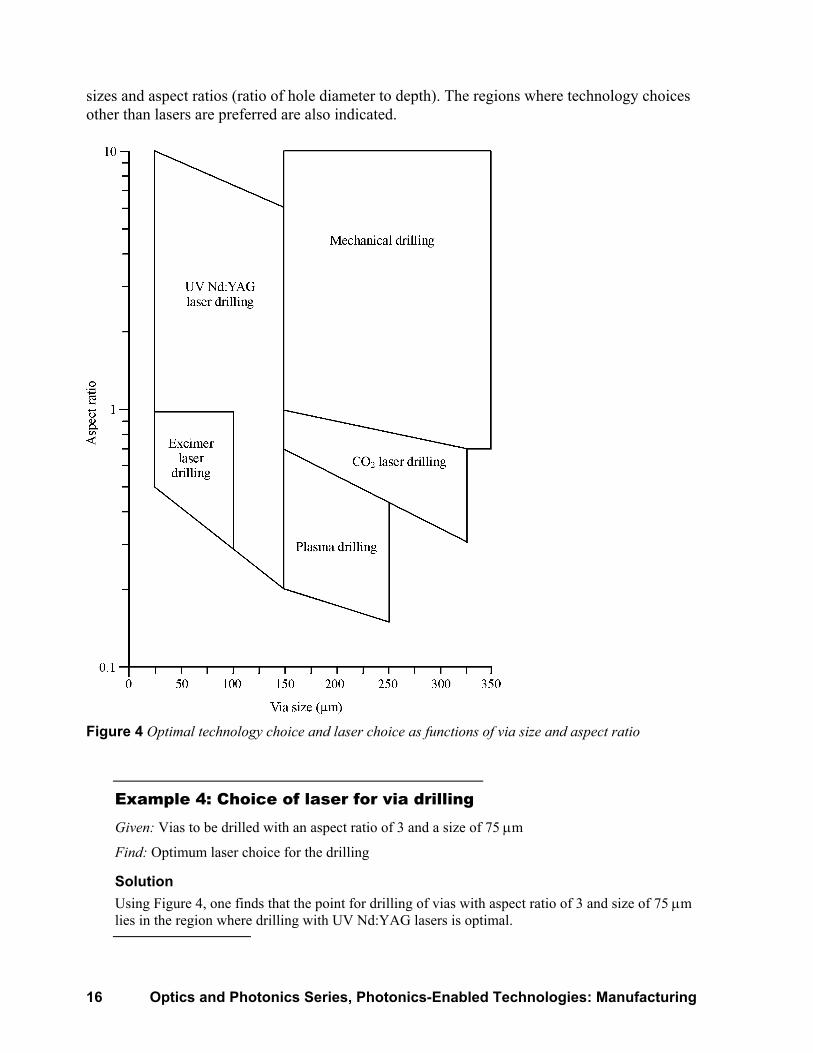
The choice of laser depends on the type of material to be drilled, the hole diameter and the depth to be drilled. Figure 4 shows the cutting technology preferred for drilling of vias of different
16 Optics and Photonics Series, Photonics-Enabled Technologies: Manufacturing
sizes and aspect ratios (ratio of hole diameter to depth). The regions where technology choices other than lasers are preferred are also indicated.
Figure 4 Optimal technology choice and laser choice as functions of via size and aspect ratio
Example 4: Choice of laser for via drilling Given: Vias to be drilled with an aspect ratio of 3 and a size of 75 µm
Find: Optimum laser choice for the drilling
Solution Using Figure 4, one finds that the point for drilling of vias with aspect ratio of 3 and size of 75 µm lies in the region where drilling with UV Nd:YAG lasers is optimal.

Laser Material Removal: Drilling, Cutting, and Marking 17
Configurations—It is of course possible to drill one via at a time, moving the beam from one hole location to the next. But because very large numbers of vias are to be drilled, techniques for drilling of many holes at a time are used. One technique is to use a mask, in which a number of holes allow the beam to pass through to the positions where vias are desired. The laser beam passes through the holes in the mask and then is focused onto the workpiece so as to form many holes at the same time. A disadvantage of this configuration is that laser energy is lost because much of the mask is not covered with holes. In this configuration, TEA CO2 lasers and excimer lasers are most often used, because they have sufficient energy per pulse to expose a significant area at the same time.
Another method that is more conserving of laser energy is the use of a phase mask. The phase mask is a quartz plate into which individual lenslets are machined, one for the location of each via. Such masks are manufactured using focused ion beams, and a mask is specific for a particular pattern of vias. The use of phase masks utilizes the laser energy much better and results in faster drilling rates. The use of phase masks eliminates the loss of laser energy that occurs because projection masks are partially opaque.
Results—Laser drilling of vias is used for small holes in a variety of materials used in the electronics industry, including FR4 (a commonly used electronic material), epoxies, polyimide, and aramid. It is used for drilling holes in composite materials, including some containing copper layers, or epoxy with glass fibers.
Laser drilling is most frequently used to produce holes with diameters in the range 25 to 150 µm at high rates, exceeding 1000 vias per minute. The materials drilled are usually relatively thin, with thicknesses typically in the range from 0.1 to 10 times the diameter of the hole to be drilled.
Applications in electronics—Via drilling has become widely accepted in the electronics industry, with many millions of vias being drilled in circuit boards each day. Via drilling is used to form complicated patterns of high-density holes in products such as video cameras and cell phones. Laser drilling of vias offers many advantages for specific production applications, such as space saving on circuit boards, speed, quality and cost.
As one example, for a personal communication system, an ultraviolet Nd:YAG laser drills vias with a diameter 150 µm into an epoxy board. Two hundred vias are required on an integrated circuit mounting pad. The vias are drilled at a rate of 1200 per minute.
Comparison with other methods—Laser drilling of vias competes with other technologies. Figure 4 has shown some of the other technologies that may compete with laser drilling. For relatively larger holes, mechanical drilling or plasma drilling may be preferred over laser drilling. For holes with diameters less than 150 µm, laser drilling is usually preferred.
Cutting Laser cutting is a very well established technology for laser materials processing. Cutting with lasers can be very efficient and cost effective.
Lasers used—The CO2 laser has been employed for industrial cutting applications for many years. Multikilowatt CO2 lasers have been used to cut metals up to 2 inches thick. The output powers for continuous CO2 lasers range up to 20 kW, but above 5 kW the beam quality decreases.

18 Optics and Photonics Series, Photonics-Enabled Technologies: Manufacturing
Relatively recent advances in CO2 laser technology have included improved radio-frequency excitation technology and turbo radial blowers. These developments have led to the introduction of CO2 lasers with a beam quality parameter of M2 < 2 at power levels of 5 kW. For power levels up to 5 kW, the beam may be focused to a small spot with high irradiance. At higher values of power, up to 20 kW, the beam quality decreases and the ability to deliver high irradiance to a workpiece does not increase much as one goes above 5 kW.
Recently, advances in Nd:YAG lasers have provided continuous diode-pumped lasers with outputs around 5 kW. Such lasers are beginning to be used for cutting, especially for applications in which flexible fiber optic beam delivery is desirable. Principally because of the cost of a multikilowatt CO2 laser system is less than that of a multikilowatt Nd:YAG laser, CO2 lasers may be expected to continue to dominate laser cutting applications, at least for the near future.
Gas shield—Laser cutting is usually performed in the presence of a shielding gas. The gas may be chemically reactive, like oxygen, or nonreactive, like nitrogen or argon. The gas may aid the cutting process by blowing molten material away from the cutting region. This means that the latent heat of vaporization does not have to be supplied to the entire amount of material to be removed and saves on laser energy requirements. In other situations, laser energy is supplemented by a jet of oxygen. The laser beam provides the heat necessary to ignite the metal in the oxygen atmosphere. Most of the energy for cutting is provided by the oxygen jet. This cutting process is called oxygen-assisted cutting.
Some considerations about laser cutting are presented in Table 5. The table classifies different materials suitable for cutting in terms of their properties—thermal conductivity and chemical reactivity). The table also lists the dominant physical mechanism for cutting each type of material.
Table 5. Laser Cutting Material Mechanism Example
Low conductivity Vaporization Cloth High conductivity, nonreactive
Flushing of liquid by gas stream Stainless steel
High conductivity, reactive Exothermic reaction with oxidizing gas Titanium
Cut speed—Figure 5 presents an example of cutting speed obtainable for oxygen-assisted cutting of stainless steel as a function of steel thickness, for different values of laser power. The cutting speeds are high enough to be of economic interest.

Laser Material Removal: Drilling, Cutting, and Marking 19
Figure 5 Typical cutting speeds for oxygen-assisted cutting of stainless steels at a number of laser powers
Effect of polarization—A practical consideration for laser cutting of metals involves the direction of the E-field polarization of the laser beam. The direction of the linear polarization should be parallel to the direction along which the cut proceeds. This yields cuts with high quality and sharp, straight edges. If the direction of the polarization is perpendicular to the direction of the cut, the quality is degraded and the edges become rough. Therefore, control of the direction of the E-field polarization of the laser beam is an important factor for obtaining high-quality cuts in metals.
In practice, to avoid having to control the direction of polarization during a complex cutting operation, many laser cutting operations use a circularly polarized beam. This produces satisfactory results and does not require continually changing the polarization during complicated cutting operations.
Industrial applications—In many industrial applications of laser cutting, laser technology and automated machining are merged to provide cost-effective cutting. When laser cutting is used with automated machining, the pattern to be cut is stored on a floppy disc. A vacuum chuck holds the material to be cut, and the beam is traversed over the surface of the workpiece under the control of the computer.
A changeover from cutting of one shape to cutting of a different shape can be accomplished rapidly, simply by changing the disc. The fixturing requirements are very simple. The introduction of a completely new shape can be considerably hastened. All that is necessary is the writing of software to control the motion of the beam over the surface of the workpiece. In this way, short production runs of complicated shapes can be done with laser cutting at reduced cost.
Laser cutting has become standard practice in the automotive industry, particularly for cutting parts used to assemble automotive frames. Rails for frames and stiffeners require holes to be cut

20 Optics and Photonics Series, Photonics-Enabled Technologies: Manufacturing
for passage of electrical cables, hydraulic lines, etc., and for cutouts where other frame members are to be attached. Highly automated systems are employed to cut round, square or rectangular holes in the rails. The holes may be located on one, two or three sides of the rails. Most of the cutting is done with multikilowatt CO2 lasers. The laser cutting capability allows the manufacturer to respond quickly to new orders for different types of parts.
Scribing Laser scribing is an alternative method of separating material samples, as opposed to cutting them. Scribing is done by drilling a series of closely spaced holes. These are “blind” holes; that is, the holes do not penetrate all the way through the workpiece. The material will then separate easily along the path of the scribed holes.
Laser scribing is notable because it does not require vaporization all the way through the material. It is thus more energy efficient than cutting and can proceed at a high rate.
Pulsed lasers are most often used for scribing. Repetitively Q-switched Nd:YAG lasers are used for scribing and separating silicon devices. Repetitively pulsed CO2 lasers are used to scribe ceramic substrates. The average power of the chosen lasers typically is in the range around 50 watts, a value high enough to scribe at economically attractive rates. Table 6 shows typical parameters for a CO2 laser used for the scribing of alumina.
Table 6. Typical CO2 Laser Parameters for Scribing of Alumina
Peak power 300 W Repetition rate 1 kHz Pulse duration 100 µsec Hole diameter 0.125 mm Hole depth 0.175 mm Scribe speed 150 mm/sec
Laser scribing has replaced the earlier method of diamond point scribing. For many applications in the electronics industry, laser scribing has become the method of choice for separating materials like alumina for use as substrates for chips.
Laser scribing is well suited for fabrication of complex shapes from brittle substrate materials. Advantages include high throughput, clean separation without contamination and elimination of tool wear. Because of these factors, laser scribing has become a fully established production tool in the ceramics and electronics industries. It has been estimated that billions of holes are drilled daily in laser scribing operations.
Link cutting Cutting of links (connections between circuit elements) has become widely used for repair of defects in integrated circuit chips. The number of elements in integrated circuits has become very large. Small defects in the circuit manufacture can cause the yield of expensive circuits to

Laser Material Removal: Drilling, Cutting, and Marking 21
be low. The approach has been to insert extra elements into circuits, test the devices, and identify faulty ones—and then use laser vaporization to cut the links to the faulty areas.
Lasers used— The lasers that have been most often used for link cutting are Q-switched solid state lasers. They include the Nd:YAG laser at wavelengths of 1064 and 532 nm, the Nd:YLF (neodymium-doped yttrium lithium fluoride) laser at wavelengths of 1047 and 1320 nm, and the Nd:YVO4 (neodymium-doped yttrium vanadate) laser at wavelengths of 1064 and 1340 nm.
All the infrared wavelengths are absorbed well by the materials that form the links. The Nd:YLF laser, because it has relatively high-pulse energy, is used for cutting relatively thick links. The Nd:YVO4 laser, with short pulse duration, is used for cutting thinner links, because it can couple its energy into a link before the energy is dissipated to the surroundings. The frequency-doubled Nd:YAG laser at 532 nm is used in cases where small focal spot size is desired.
The pulse energy is usually in the range of a few tenths of a millijoule and the pulse duration in the range of a few tens of nanoseconds.
Use in repairs—Link cutting is performed by vaporization of conducting lines that connect circuit elements. The links that are to be cut are metals, like copper and aluminum, or polysilicon. The links typically have a thickness of a few micrometers.
A typical laser-based repair involves the repair of large memory arrays, like dynamic random access memories (DRAMS). The memory capacity of a chip has increased to the range of hundreds of megabytes. The cost of processing such chips is high and the yield would be unacceptably low without a means for repairing them.
The memory elements are arranged in rows and columns. Automated test equipment identifies faulty elements. The laser beam is focused on the conductive links that connect the row or column containing a faulty element and the beam vaporizes the links, thereby removing the defective elements from the circuit.
Memory chips have been produced with “redundancy,” that is, with extra rows and columns of memory elements, so as to allow removal of defective elements.
In one example, a one-megabit DRAM is manufactured with 32 extra rows of 512 bits and 32 extra pairs of columns of 256 bits. The links, which are polysilicon film, are cut with 1060-nm Nd:YAG laser pulses. Typically, a few tens of links will be cut on a chip.
Repair of defects in expensive high-density circuits has become standard practice in the microelectronics industry, improving yields substantially.
Resistor trimming Trimming of resistors means increasing the resistance of a resistor by making a cut partially through it, so as to adjust the value of the resistance to a desired value. Trimming is also used for other components, such as capacitors.
Reasons for use—Resistors in electronic circuits are fabricated as films, either by printing from a liquid ink (thick-film resistors) or by vacuum deposition (thin-film resistors). It is usually difficult to control the values of the resistance to within the tolerances required by the circuit.
When resistors are fabricated, there is a distribution in the values of resistance that are obtained. It is common for there to be a variation of 10% or more in the values of resistance. If the
22 Optics and Photonics Series, Photonics-Enabled Technologies: Manufacturing
resistors are fabricated with intentionally low resistance, and then are trimmed (cut partly through) so as to increase the resistance, the tolerances in the resistance can be much reduced, to perhaps 0.1%.
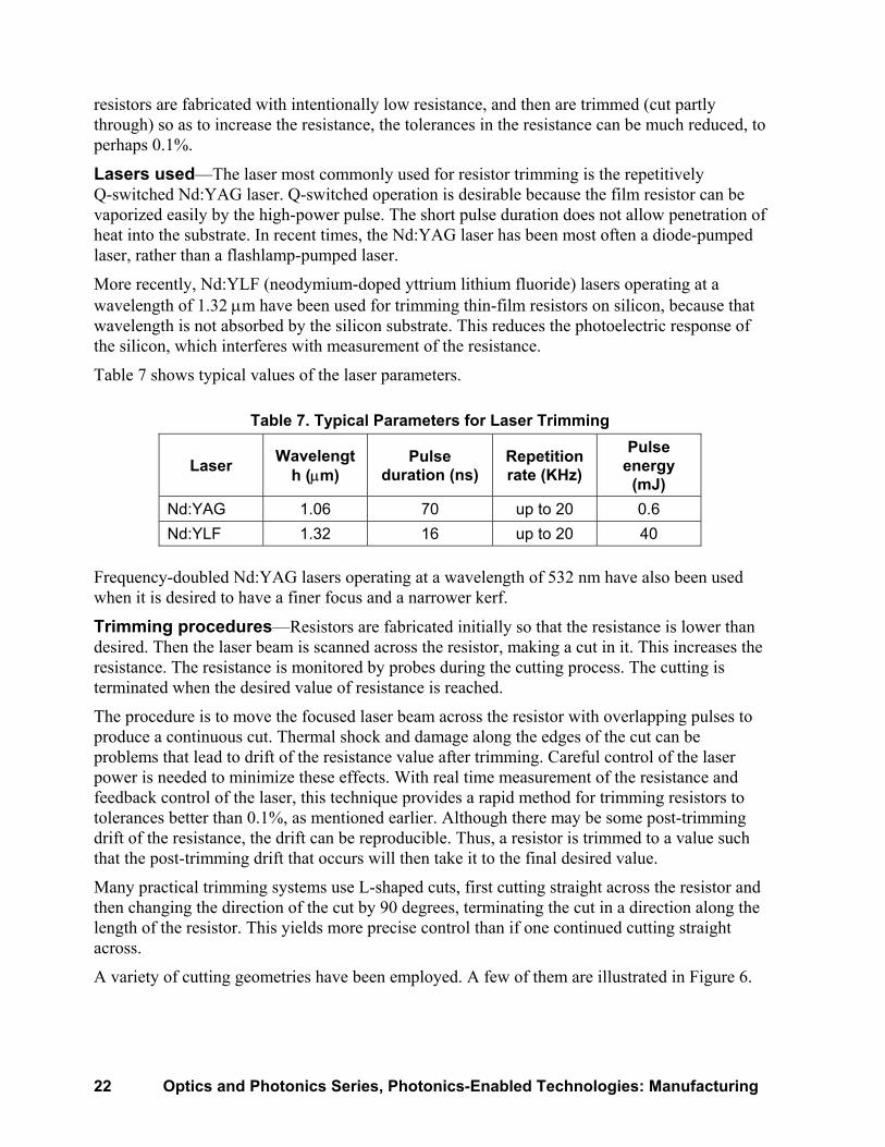
Lasers used—The laser most commonly used for resistor trimming is the repetitively Q-switched Nd:YAG laser. Q-switched operation is desirable because the film resistor can be vaporized easily by the high-power pulse. The short pulse duration does not allow penetration of heat into the substrate. In recent times, the Nd:YAG laser has been most often a diode-pumped laser, rather than a flashlamp-pumped laser.
More recently, Nd:YLF (neodymium-doped yttrium lithium fluoride) lasers operating at a wavelength of 1.32 µm have been used for trimming thin-film resistors on silicon, because that wavelength is not absorbed by the silicon substrate. This reduces the photoelectric response of the silicon, which interferes with measurement of the resistance.
Table 7 shows typical values of the laser parameters.
Table 7. Typical Parameters for Laser Trimming
Laser Wavelength (µm)
Pulse duration (ns)
Repetition rate (KHz)
Pulse energy
(mJ) Nd:YAG 1.06 70 up to 20 0.6 Nd:YLF 1.32 16 up to 20 40
Frequency-doubled Nd:YAG lasers operating at a wavelength of 532 nm have also been used when it is desired to have a finer focus and a narrower kerf.
Trimming procedures—Resistors are fabricated initially so that the resistance is lower than desired. Then the laser beam is scanned across the resistor, making a cut in it. This increases the resistance. The resistance is monitored by probes during the cutting process. The cutting is terminated when the desired value of resistance is reached.
The procedure is to move the focused laser beam across the resistor with overlapping pulses to produce a continuous cut. Thermal shock and damage along the edges of the cut can be problems that lead to drift of the resistance value after trimming. Careful control of the laser power is needed to minimize these effects. With real time measurement of the resistance and feedback control of the laser, this technique provides a rapid method for trimming resistors to tolerances better than 0.1%, as mentioned earlier. Although there may be some post-trimming drift of the resistance, the drift can be reproducible. Thus, a resistor is trimmed to a value such that the post-trimming drift that occurs will then take it to the final desired value.
Many practical trimming systems use L-shaped cuts, first cutting straight across the resistor and then changing the direction of the cut by 90 degrees, terminating the cut in a direction along the length of the resistor. This yields more precise control than if one continued cutting straight across.
A variety of cutting geometries have been employed. A few of them are illustrated in Figure 6.

Laser Material Removal: Drilling, Cutting, and Marking 23
Figure 6 Laser trimming cut-geometries of resistor material
The simple plunge cut allows the highest rate of trimming but does not offer as accurate a final value of resistance. The L-cut offers a higher total change of resistance and better tolerance for the final resistance value. The serpentine trim pattern offers the possibility of large changes in resistance value. The U-cut offers high voltage isolation, in order to avoid shorting across the cut.
The L-cut seems to be the most widely used configuration for current trimming operations.
An alternative to simply trimming resistors to predetermined values of resistance is called functional trimming, in which the circuit is in operation during the trimming operation. The performance of the circuit is monitored during the trimming. The trimming operation is ended when the circuit is functioning properly. Functional trimming can improve the performance of the circuit, but does require fully automatic testing.
Trimming of thin-film on ceramic or silicon—Thin-film resistors like nickel-chromium or tantalum nitride, deposited on ceramic or silicon substrates, are more expensive than thick-film resistors, but offer better stability and lower values of the temperature coefficient of resistance. The Nd:YLF laser wavelength near 1.3 µm is well absorbed by the materials like nickel-chromium and still allows the capability of focusing the beam to a small spot.
As compared to 1.06 µm, the use of a wavelength near 1.3 µm allows functional trimming at higher rates. The use of 1.3 µm lasers also eliminates troublesome photoelectric response in silicon substrates. It was found that functional trimming of thin-film resistors on silicon with 1.06 µm light produced free electrons and holes in the silicon and interfered with the monitoring of the trimming. The use of the 1.3 µm wavelength eliminated this problem.
Results—Laser trimming of resistors offers a number of advantages as compared to abrasive trimming, which previously was the standard method of trimming. Laser trimming avoids contamination by abrasive particles. It provides fast and accurate trimming in a completely automated system.
Because of these advantages, laser trimming has become widely used as a standard technique in the electronics industry. It has almost completely displaced the earlier standard technique of abrasive trimming. Laser trimming of resistors and other components has been a highly successful practical application of laser material removal, leading to improved methods of electronic circuit fabrication.
24 Optics and Photonics Series, Photonics-Enabled Technologies: Manufacturing
Marking Marking and engraving of products with alphanumeric characters, bar codes, symbols, and logos has become a cost-effective industrial application of laser-produced material removal. Laser marking of a diverse variety of parts and products during their manufacturing process has become well established.
A laser marking system creates marks by removing material. The mark can be produced by removal of surface layers of the basic material of which the part is made or by removing a coating layer and revealing a contrasting surface of the base material beneath the coating.
Advantages of laser marking include the features of being a noncontact and contamination-free process, of permanence and high speed. Laser marking offers cost advantages in comparison with other marking methods. The cost advantages derive from the fact that a laser mark is a high-quality, permanent mark. This factor reduces the number of reject parts.
Laser marking has been used for such diverse applications as marking housings for cardiac pacemakers, making nameplates for transformers, identifying carbide drill-bit tips, identifying silicon wafers during processing, bar-code labeling of printed circuit boards, and imprinting identifying numbers on typewriters. Laser marking has become an important and growing technology in the manufacturing industry.
Lasers used—Lasers used for marking include Nd:YAG lasers and CO2 TEA lasers. Nd:YAG laser marking generally uses a series of pulses, either to produce a dot matrix pattern or to form continuous lines by overlapping pulses. Nd:YAG laser systems are suitable for marking metals, ceramics and silicon.
Excimer lasers, ArF (193 nm), KrF (248 nm), XeCl (308 nm) and XeF # (351 nm) have also been used for marking, particularly with materials that have high absorption in the ultraviolet portion of the spectrum.
CO2 TEA lasers can produce an entire pattern in a single pulse if the laser is projected through a mask that forms the desired pattern. Such systems are most suitable for materials that are easily vaporized, such as plastic, paper, and cardboard products.
Dot matrix marking—In the dot matrix method, one scans the laser beam over the surface of the part and modulates it to vaporize a small amount of material in selected positions, so as to produce a mark. The mark consists of a pattern of small holes, produced by many laser pulses. The mark may be alphanumeric characters or any other desired pattern. The pattern of holes defines the desired characters or figures.
This method is used on materials that have relatively high latent heat of vaporization, like metals or semiconductors. It uses lasers that have relatively high peak powers, like Q-switched Nd:YAG or excimer lasers.
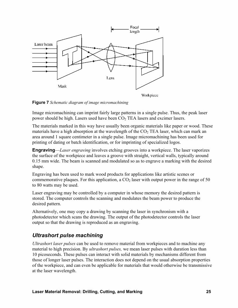
Image micromachining—Image micromachining can produce a complicated pattern in a single laser pulse. A mask with the desired pattern is placed in the laser beam. A lens images the pattern of the mask on the workpiece surface. The arrangement is shown in Figure 7. When the laser power is high enough, the surface of the workpiece is vaporized and an image of the mask is imprinted on the workpiece.
Laser Material Removal: Drilling, Cutting, and Marking 25
Figure 7 Schematic diagram of image micromachining
Image micromachining can imprint fairly large patterns in a single pulse. Thus, the peak laser power should be high. Lasers used have been CO2 TEA lasers and excimer lasers.
The materials marked in this way have usually been organic materials like paper or wood. These materials have a high absorption at the wavelength of the CO2 TEA laser, which can mark an area around 1 square centimeter in a single pulse. Image micromachining has been used for printing of dating or batch identification, or for imprinting of specialized logos.
Engraving—Laser engraving involves etching grooves into a workpiece. The laser vaporizes the surface of the workpiece and leaves a groove with straight, vertical walls, typically around 0.15 mm wide. The beam is scanned and modulated so as to engrave a marking with the desired shape.
Engraving has been used to mark wood products for applications like artistic scenes or commemorative plaques. For this application, a CO2 laser with output power in the range of 50 to 80 watts may be used.
Laser engraving may be controlled by a computer in whose memory the desired pattern is stored. The computer controls the scanning and modulates the beam power to produce the desired pattern.
Alternatively, one may copy a drawing by scanning the laser in synchronism with a photodetector which scans the drawing. The output of the photodetector controls the laser output so that the drawing is reproduced as an engraving.
Ultrashort pulse machining Ultrashort laser pulses can be used to remove material from workpieces and to machine any material to high precision. By ultrashort pulses, we mean laser pulses with duration less than 10 picoseconds. These pulses can interact with solid materials by mechanisms different from those of longer laser pulses. The interaction does not depend on the usual absorption properties of the workpiece, and can even be applicable for materials that would otherwise be transmissive at the laser wavelength.

26 Optics and Photonics Series, Photonics-Enabled Technologies: Manufacturing
The interaction of ultrashort pulse laser light is no longer a thermal process as it is at longer pulse durations. In conventional thermal processing, the energy of the laser beam is absorbed at or near the surface of the target and is conducted into the material by thermal conduction. For the very short, high-power pulses, the accepted mechanism is multiphoton ionization, a process in which individual atoms become ionized by the nearly simultaneous absorption of the energy of a number of photons. The very high electric field associated with the light strips electrons from their parent atoms and accelerates them to high energies. The energetic electrons collide with lattice atoms and transfer energy to them. These atoms in turn are ionized, producing still more free electrons. This leads to a dense absorbing plasma.
Multiphoton absorption can occur even in solids that would be transparent at the laser wavelength at lower values of irradiance. It occurs on a time scale short compared to the time needed for thermal conduction, so that there is effectively no heat-affected zone around the machined area. Ultrashort laser pulses may be used to machine target materials to micrometer precision with no damage to the surrounding material.
Much of the work on ultrashort pulse machining has been done with titanium-doped sapphire (Ti:sapphire) lasers, which usually operate at a wavelength around 800 nm. Table 8 presents typical properties for Ti:sapphire lasers suitable for ultrashort pulse machining.
Table 8. Typical Parameters of Ultrashort Pulse Ti:sapphire Lasers
Pulse energy 1 µjoule Pulse duration 0.1 picosec Pulse repetition rate 1000 Hz Average power 1 mW Peak power 107 W
Ultrashort pulse laser machining can be used with metals, biological materials and dielectrics, like sapphire, diamond, silicon carbide, titanium nitride, etc. The depth of material removed is around 0.5 µm per laser pulse, both for metals and dielectrics. Figure 8 shows the depth of material removed from stainless steel by a Ti:sapphire laser beam as a function of laser fluence striking the surface at normal incidence. The laser has a pulse duration 0.12 picosecond and wavelength 825 nm. As the laser fluence increases, the amount of material removed increases rapidly at first, and then saturates near 14 J/cm2.

Laser Material Removal: Drilling, Cutting, and Marking 27
Figure 8 Depth of material removed from stainless steel per pulse (Based on data from Lawrence Livermore National Laboratory)
In one application of ultrafast machining, machining of explosives has been demonstrated. Conventional methods of machining explosives are risky, often leading to detonation. Conventional laser irradiation with longer laser pulses can also detonate the explosive. But with subpicosecond laser irradiation, the process occurs too quickly for transfer of energy to the surrounding explosive material. In one example, cuts were successfully made in 2-mm thick pellets of the explosive PETN by a Ti:sapphire laser with pulse duration 0.12 picoseconds.
In summary, ultrafast laser processing offers prospects for cutting, drilling, and sculpting virtually all solid materials with very high precision and negligible heat-affected zones.
LABORATORY Materials CO2 laser (CW, 20 watts or so power output) Germanium lens Lens mount for germanium lens Power meter for CO2 laser Samples of plastic (lucite about 0.01 inch thick) Samples of ceramic (alumina about 0.01 inch thick) Sample holder for plastic and alumina Motorized drive for sample Carbon block Diamond wheel Measuring microscope Stopwatch Pulsed solid-state laser (ruby or Nd:YAG with output of a few joules)
28 Optics and Photonics Series, Photonics-Enabled Technologies: Manufacturing
Glass lens Lens mount for glass lens Energy meter for solid-state laser output Samples of metal (steel and tungsten about 2 mm thick) Sample holder for metal samples
Procedures Precautions: Familiarize yourself with and follow all appropriate safety rules concerning the use of high-power lasers. Avoid the hazards of high voltages.
You will carry out the following procedures, each of which involves removal of material from a target by a focused laser beam.
1. Cutting plastic 2. Scribing ceramic 3. Drilling holes in metals
These operations are representative of typical uses of lasers for material removal in industry. The laser power will not be as high and the fixturing facilities not as sophisticated as those used in industrial production, but these activities should give you an idea of the capabilities of laser material removal. You will gain practical knowledge about how to focus and align a laser beam for the purpose of removing material from a target.
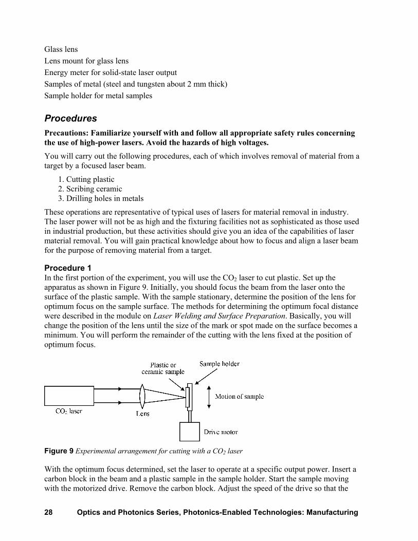
Procedure 1 In the first portion of the experiment, you will use the CO2 laser to cut plastic. Set up the apparatus as shown in Figure 9. Initially, you should focus the beam from the laser onto the surface of the plastic sample. With the sample stationary, determine the position of the lens for optimum focus on the sample surface. The methods for determining the optimum focal distance were described in the module on Laser Welding and Surface Preparation. Basically, you will change the position of the lens until the size of the mark or spot made on the surface becomes a minimum. You will perform the remainder of the cutting with the lens fixed at the position of optimum focus.
Figure 9 Experimental arrangement for cutting with a CO2 laser
With the optimum focus determined, set the laser to operate at a specific output power. Insert a carbon block in the beam and a plastic sample in the sample holder. Start the sample moving with the motorized drive. Remove the carbon block. Adjust the speed of the drive so that the

Laser Material Removal: Drilling, Cutting, and Marking 29
plastic is cut. If the plastic is not being cut, slow the drive down until it is cut. Successful completion of this part of the experiment requires obtaining a cut through the plastic.
When a cut is obtained, increase the speed of the drive to the maximum value at which a cut is still obtained. You may need several trials to obtain the maximum speed. Measure the maximum speed. This measurement may be made with a stopwatch and a known distance of sample travel.
Then change the laser output power and repeat the steps above. Obtain pairs of values of laser power and maximum cutting speed.
For analysis, state how the cutting rate varies with laser power. Plastic surfaces are good absorbers at the CO2 laser wavelength. How does this aid the cutting operation?
Procedure 2 In the second part of the experiment, you will use the same CO2 laser and the same experimental arrangement to now scribe thin ceramic plates. Scribing means cutting or scoring a line along the surface so that the ceramic will break and separate along the line when force is applied. Scribing does not mean cutting all the way through the sample. Rather it means removing a little material along the desired line. Scribing does not require as much laser power as cutting because not as much material must be removed. The scribe line should accurately determine where the ceramic will break. This process has become widely used in industry for separating ceramic substrates that are used in electronic fabrication.
The beam should be focused—just as Procedure 1—on the surface of a ceramic sample. The arrangement is again as shown in Figure 9. Use the motorized drive to move the sample across the beam so that the laser will scribe a line across the surface. The ceramic should not be cut all the way through. You may have to make several trials to obtain a satisfactory combination of laser power and travel speed. When a line has been scored across the surface of the sample, turn off the laser, remove the sample, and snap the ceramic apart with your hands. It should break easily along the line defined by the scribing. Successful completion of this part of the experiment involves producing a scribed line in the ceramic surface and breaking the ceramic apart along the line.
Procedure 3 In the third portion of the experiment, you will drill holes in metallic samples with a solid-state laser. Use the experimental arrangement in Figure 10. In this part of the experiment, the sample will be stationary during drilling. After drilling a hole at one position, move to a new position. You will drill a hole with each laser pulse.
Figure 10 Experimental arrangement for drilling holes in metals with a pulsed solid-state laser

30 Optics and Photonics Series, Photonics-Enabled Technologies: Manufacturing
Determine the optimum focal position for the lens, as in Procedures 1 and 2. Keep the lens at this position. Measure the output of the laser with the energy meter for various settings of the voltage on the laser power supply. Plot the results so that you will know the laser output for a given voltage setting.
Allow the laser beam to strike the surface and drill holes. For each laser pulse a new area of the sample should be drilled. For successful completion of this part of the experiment, holes must be drilled into the metal samples. Drill holes into each of two different metals, for example, steel and tungsten. Drill a number of holes into each material, using one laser pulse per hole. Obtain holes for a number of different values of laser energy.
Now, cut cross sections through the holes with the diamond wheel. The orientation of the cross section should be as shown in Figure 11. With the measuring microscope, measure the depth of the holes. Plot the hole depth as a function of laser energy.
Figure 11 Schematic diagram of cross section of hole drilled in metal with a pulsed high-power laser
For analysis, state how the hole depth varies with laser energy. For a fixed laser energy, compare the depth of the holes in the two different metals and state the effects of the latent heat of vaporization on the hole depths. (Values for latent heat of vaporization for different metals can be obtained from standard reference books, such as the Handbook of Chemistry and Physics [CRC Press, 2004].) Observe the cross sections of the holes and note the taper, the lip of material around the entrance of the hole and the roughness of the sides

Laser Material Removal: Drilling, Cutting, and Marking 31
EXERCISES 1. Describe, in terms similar to those in the text, how the high-power beam from a laser
vaporizes surfaces.
2. Enumerate the advantages and limitations of the use of lasers for hole drilling.
3. Calculate to two significant figures the maximum depth of a hole that can be drilled in iron by an Nd:YAG laser pulse containing 1.2 joules of energy and focused to a spot of 0.043-cm diameter on the surface of the iron. Assume that all the energy is absorbed and that the ambient temperature is 20 degrees C. The properties of iron are:
Density = 7.86 gm/cm3
Latent heat of vaporization = 6300 J/gm Specific heat = 0.63 J/gm-degree C Boiling point = 2887 degrees C
4. Describe, in terms similar to those in the text, the process of laser-based resistor trimming.
5. Name the two types of lasers most often used for laser cutting and the range of power in which they operate.
6. Describe, in terms similar to those used in the text, the three methods most often used for laser marking.
7. Vias are to be drilled with an aspect ratio of 0.6 and size of 50 µm. What type of drilling would be optimal?
REFERENCES Duley, W.W. CO2 Lasers: Effects and Applications. New York: Academic Press 1976.
(Chapters 5–7) Gabzdyl, J. Cutting on edge. Industrial Laser Solutions for Manufacturing, June 2004, p. 19. Harris, J., and M. Brandt. Cutting thick steel plate. Industrial Laser Solutions for
Manufacturing, August 2004, p. 34. Lehner, C. Drilling with light. Industrial Laser Solutions for Manufacturing, January 2004,
p. 30. Oakes, M. An introduction to thick film resistor trimming by laser. Optical Engineering,
May/June 1978, p. 217. Orr, I. Flexible robotic cutting. Industrial Laser Solutions for Manufacturing, September 2004,
p. 20. Ready, J.F. Industrial Applications of Lasers. San Diego: Academic Press, 1997. (Chapter 16) Ready, J.F., editor. LIA Handbook of Lasers Materials Processing. Orlando: Laser Institute of
America, 2001. (Chapters 12–19) Schluter, H. CO2 lasers make the cut. Photonics Spectra, June 2003, p. 80.