optical and mechanical design of the antarctic
TRANSCRIPT

Optical and mechanical design of the Antarctic Submillimeter Telescopeand Remote Observatory
Antony A. Starka)Smithsonian Astrophysical Observatory, 60 Garden Street, Cambridge, Massachusetts 02138
Richard A. Chamberlin and James G. IngallsBoston University, Department of Astronomy, 725 Commonwealth Avenue, Boston, Massachusetts 02215
Jingquan ChengNational Radio Astronomy Observatory, 949 North Cherry Avenue, Tucson, Arizona 85721
Gregory WrightBell Laboratories, Crawford Hill, Holmdel, New Jersey 07733
~Received 1 August 1996; accepted for publication 5 February 1997!
Antarctic Submillimeter Telescope and Remote Observatory~AST/RO!, a 1.7 m diameter telescopefor astronomy and aeronomy studies at wavelengths between 200 and 3000mm, was installed at theSouth Pole during the 1994–95 Austral summer. The optical design is Gregorian, offset in bothazimuth and elevation, with the exit pupil at the chopping tertiary mirror: this arrangement providesfor consistent illumination of the primary mirror even when the beam is thrown one degree or moreon the sky. Aberrations are minimized by the choice of secondary mirror offset angle. Alignment isaccomplished by mechanical means. There is a Coude´ focus in a warm, spacious receiver room andalso a Nasmyth focus. Both the elevation and azimuth axes are driven by two pinion gears withopposed torques to eliminate backlash. The encoders are unusually robust but have high friction,necessitating a stiff coupling. The azimuth limit switch scheme permits 1.5 rotations, but theswitches will operate under extreme conditions with no single point of failure. The instrument isnow operational with four heterodyne receivers and three acousto-optical spectrometers. ©1997American Institute of Physics.@S0034-6748~97!02805-0#
bitounmactth
nttheto
na
v
s
at a
lta-
rayofpt-
i-
is
ls,Thether-ons,oc-andcalgo-eto
de-
I. INTRODUCTION
The Antarctic Submillimeter Telescope and Remote Oservatory became operational in January 1995 at the UnStates National Science Foundation Amundsen-Scott SPole Station.1,2 The observatory will carry out programs iastronomy and aeronomy, using a 1.7-m-diasubmillimeter-wave antenna. The immediate scientific goof this instrument are heterodyne spectroscopy of galaatomic and molecular clouds and molecular lines inearth’s stratosphere at wavelengths near 600mm, but theantenna was designed to be a general-purpose instrumethe millimeter, submillimeter, and far-infrared. The SouPole is the best ground-based observatory site for thwavelengths, because the cold climate dessicatesatmosphere,3,4 and water vapor is the dominant sourceatmospheric opacity at submillimeter wavelengths.
The design criteria combine logistical and site exigecies with the optimization of the instrument assubmillimeter-wave telescope:
~1! all systems must operate reliably in the South Pole enronment~see Table I!;
~2! on-site assembly and alignment is minimal;~3! all components must fit into shipping containers le
than 2.4 m in height and width~to fit in the cargo bay ofan LC130 aircraft!;
~4! the telescope is fully steerable and slews at 2° s21 orfaster;
a!Electronic mail: [email protected]
2200 Rev. Sci. Instrum. 68 (5), May 1997 0034-6748/97/68
Downloaded¬01¬Aug¬2007¬to¬128.103.60.225.¬Redistribution¬subject
-edth
lsice
for
sehef
-
i-
s
~5! the beam can be chopped a degree in cross-elevation10 Hz rate;
~6! several receiver packages can be mounted simuneously;
~7! the field-of-view is large enough to accommodate ardetectors~the focal plane should contain hundredsdiffraction-limited resolution elements that have acceably small aberrations!;
~8! the beam efficiency is maximized and spillover minmized;
~9! the beam is diffraction-limited and the beam qualityhigh for wavelengths as short asl200 mm ~surface ac-curacy better than 10mm!;
~10! pointing accuracy must be within 1/10th beam atl200mm ~3 s of arc!;
~11! operation is mostly automatic.
Aside from extreme cold and wind-driven ice crystathe South Pole is a benign environment for telescopes.highest recorded wind speed in nearly 40 years of weastation operation is only 24 m/s.5 Other problems often encountered in telescope operations, such as wet conditirapid temperature variations, and insect swarms, do notcur at the South Pole. This article describes the opticalmechanical design of the AST/RO instrument. The optidesign, described in Sec. II, is a novel type of offset Grerian, with the tertiary mirror located at the exit pupil of thinstrument. The method by which these optics are madetrack astronomical objects in the Polar environment isscribed in Sec. III.
(5)/2200/14/$10.00 © 1997 American Institute of Physics
¬to¬AIP¬license¬or¬copyright,¬see¬http://rsi.aip.org/rsi/copyright.jsp

pr-heaat
hetoir-es,the
ughus
e-kethemest.ec-ister-r inl orm-Hzal oroft
n-tema-gees
an-oss-hoseeters inan-ion,itsithe--ni-
rra-f theuiltfor
ater.a-ruc-go-hichve atheIny
praeacarthloeds
II. OPTICAL DESIGN
AST/RO is a fully steerable, offset Gregorian telescowith a tertiary chopper mirror at the exit pupil and a foumirror Coudearrangement. Figure 1 is a schematic of toptical design. The primary mirror is an offset section ofparaboloid. The secondary mirror is a section of a prol
TABLE I. Physical environment of the AST/RO telescope.
Altitude 2847 mLatitude W 45°538Longitude S 89°598409
Average pressurea 680 mbMinimum temperaturea 282 °CMaximum temperaturea 214 °CAverage temperaturea 249 °CAverage wind speeda 5.8 m s21
Maximum wind speeda 24 m s21
Median water vapor column in summerb 0.47 mm PWVMedian water vapor column in winterb 0.25 mm PWV
Median observed zenith transmission at 609mmWavelength in winterb 0.50
Median calculated zenith transmission at 350mmWavelength in winterc 0.76
aSchwerdtfeger~Ref. 5!.bChamberlinet al. ~Ref. 4!.cBally ~Ref. 3!.
FIG. 1. Schematic of the AST/RO optical system. For purposes of resentation, the beam path has been flattened and the reader should imthat the primary and secondary mirrors are rotated by 90° out of the planthe page around the vertical ‘‘fold line.’’ Note that rays diverging frompoint on the primary mirror reconverge at the chopping tertiary mirror, sinthe tertiary is at the exit pupil of the instrument. The tertiary and quaternmirrors are flat. The calibration loads are in a Dewar to the side ofCoudebeam entering along the azimuth axis. The ambient temperatureis on a linear actuator and can slide in front of the sky port. Motorizchopper mirrors switch the receiver beam from the cooled loads to theor to the ambient temperature load.
Rev. Sci. Instrum., Vol. 68, No. 5, May 1997
Downloaded¬01¬Aug¬2007¬to¬128.103.60.225.¬Redistribution¬subject
e
e
spheroid. The tertiary and quaternary mirrors are flat. Ttertiary mirror is located at the exit pupil and also servesdirect the beam along the elevation axis. The quaternary mror is at the intersection of the elevation and azimuth axand directs the beam through a 140-mm-diam hole inazimuth axis bearing and encoder to the Coude´ room below.If the quaternary mirror is removed, the beam passes throa 0.2 m hole in the elevation bearing to a Nasmyth focplatform.
Avoidance of internal reflections is important to the dsign of a submillimeter-wave single-dish telescope liAST/RO. Any receiver or detector placed at the focus ofinstrument will necessarily launch into the telescope soamount of submillimeter-wave power in the band of intereIf there is a reflection in the system, for example at the sondary mirror some 3 m distant, then a resonant cavityformed whose modes are spaced at roughly 50 MHz invals, and spurious features at those intervals will appeathe spectrometer whenever there is a shift in power levesmall change in the cavity. Submillimeter-wave spectroeters cover more than 1 GHz of bandwidth, and a 50 Mspurious feature can masquerade as a typical astronomicatmospheric line with a Doppler broadening;30 km s21. All of the optics in AST/RO are offset so thainternal reflections and resonances do not occur.
Like all radio telescopes, AST/RO has a diffractiolimited beam, and diffraction effects will tend to dominathe classical optical aberrations such as coma and astigtism. Moving outward from the center of the sagittal imasurface, aberrational blur is significant only when it becomcomparable to diffraction blur. Dragone6 has shown that ifthe offset angles in an offset Cassegrain or Gregoriantenna are chosen correctly, then aberrations and crpolarization effects in an offset antenna are the same as tin a conventional on-axis antenna with the same diamand focal length. The beam efficiency and sidelobe levelthe off-axis antenna are better than those in the on-axistenna, because in the on-axis design there will be diffractreflection, and blockage from the secondary mirror andsupports. An off-axis Cassegrain or Gregorian antenna wcorrectly chosen offset angles will always be optically suprior in the diffraction-limited regime to a similar on-axis configuration, although the off-axis antenna may be mechacally more complex and expensive.
A. Beam chopper considerations
Gregorian telescopes have a small advantage in abetion and image curvature over Cassegrain telescopes osame diameter and focal length, but are less commonly bbecause the primary-to-secondary distance is larger andon-axis Gregorian designs the aperture blockage is greAperture blockage is not a problem for off-axis configurtions. Larger primary-to-secondary distance can be a sttural disadvantage, especially for large instruments. Grerian telescopes do, however, have a significant feature wCassegrain telescopes do not: Gregorian telescopes hareal exit pupil, a position along the beam path wheresecondary forms an image of the primary mirror surface.AST/RO, the exit pupil is the location of the flat tertiar
e-gineof
eyead
ky
2201Submillimeter telescope
¬to¬AIP¬license¬or¬copyright,¬see¬http://rsi.aip.org/rsi/copyright.jsp
1ll
ri
arontstexorotththa-t
d-n
irr.
err
am,beenedbe
ena
isnotryear
be-
dllyter-ry.roidaisthe
he-
isits
-
9.
d authomtheicalHzbe-
sed.
ry
areis
mirror, a motor-driven, rotating chopper, as shown in Fig.This location for the chopper is crucial to its operation. Arays which strike the primary mirror~which is to say, all raysadmitted by the telescope system! also strike the choppemirror. Furthermore, changing the angle of the chopper mror only changes the direction of the rays at the primmirror, not their position. Imagine time-reversed radiatipropagating through the telescope, so that the receiver aca transmitter. The beam launched by the receiver illuminathe chopper mirror. Since the chopper mirror is at the epupil, this illumination pattern maps onto the primary mirrwith a mapping which is independent of chopper mirrangle, so that the illumination pattern does not change aschopper is rotated. The chopper tilts the phase front ofGaussian beam striking the primary without changingpower distribution pattern. In forward-time, spillover radition seen by the receiver does not change significantly aschopper is rotated.
The position of the exit pupil is not far from the seconary mirror, slightly further from the secondary mirror thathe distance to the prime focus~the prime focus is pointF1
in Fig. 2!. Tilting the chopper by an angleuc results in abeam throw on the sky of
us.2~F1I 1!
~F1I 2!•uc ,
whereF1I 1 is the short focal distance of the secondary mror and F1I 2 is the focal distance of the primary mirroSome observing methods requireus;3°, while(F1I 1)/(F1I 2);
112, so the angle through which the chopp
rotates can be fairly large,uc;18°. The center of choppe
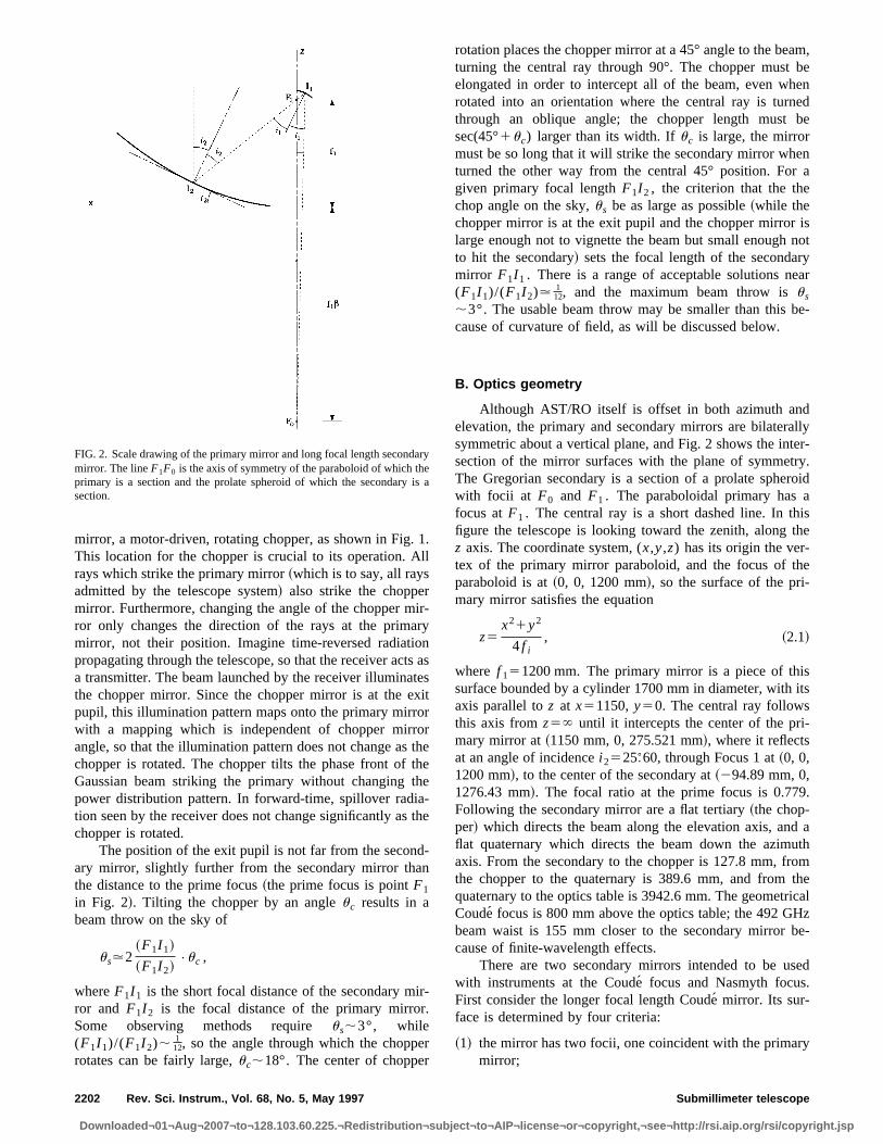
FIG. 2. Scale drawing of the primary mirror and long focal length secondmirror. The lineF1F0 is the axis of symmetry of the paraboloid of which thprimary is a section and the prolate spheroid of which the secondarysection.
2202 Rev. Sci. Instrum., Vol. 68, No. 5, May 1997
Downloaded¬01¬Aug¬2007¬to¬128.103.60.225.¬Redistribution¬subject
.
r-y
assit
rheee
he
-
rotation places the chopper mirror at a 45° angle to the beturning the central ray through 90°. The chopper mustelongated in order to intercept all of the beam, even whrotated into an orientation where the central ray is turnthrough an oblique angle; the chopper length mustsec(45°1uc) larger than its width. Ifuc is large, the mirrormust be so long that it will strike the secondary mirror whturned the other way from the central 45° position. Forgiven primary focal lengthF1I 2 , the criterion that the thechop angle on the sky,us be as large as possible~while thechopper mirror is at the exit pupil and the chopper mirrorlarge enough not to vignette the beam but small enoughto hit the secondary! sets the focal length of the secondamirror F1I 1 . There is a range of acceptable solutions n(F1I 1)/(F1I 2).
112, and the maximum beam throw isus
;3°. The usable beam throw may be smaller than thiscause of curvature of field, as will be discussed below.
B. Optics geometry
Although AST/RO itself is offset in both azimuth anelevation, the primary and secondary mirrors are bilaterasymmetric about a vertical plane, and Fig. 2 shows the insection of the mirror surfaces with the plane of symmetThe Gregorian secondary is a section of a prolate sphewith focii at F0 and F1 . The paraboloidal primary hasfocus atF1 . The central ray is a short dashed line. In thfigure the telescope is looking toward the zenith, alongz axis. The coordinate system, (x,y,z) has its origin the ver-tex of the primary mirror paraboloid, and the focus of tparaboloid is at~0, 0, 1200 mm!, so the surface of the primary mirror satisfies the equation
z5x21y2
4 f i, ~2.1!
where f 151200 mm. The primary mirror is a piece of thsurface bounded by a cylinder 1700 mm in diameter, withaxis parallel toz at x51150,y50. The central ray followsthis axis fromz5` until it intercepts the center of the primary mirror at~1150 mm, 0, 275.521 mm!, where it reflectsat an angle of incidencei 2525&60, through Focus 1 at~0, 0,1200 mm!, to the center of the secondary at~294.89 mm, 0,1276.43 mm!. The focal ratio at the prime focus is 0.77Following the secondary mirror are a flat tertiary~the chop-per! which directs the beam along the elevation axis, anflat quaternary which directs the beam down the azimaxis. From the secondary to the chopper is 127.8 mm, frthe chopper to the quaternary is 389.6 mm, and fromquaternary to the optics table is 3942.6 mm. The geometrCoudefocus is 800 mm above the optics table; the 492 Gbeam waist is 155 mm closer to the secondary mirrorcause of finite-wavelength effects.
There are two secondary mirrors intended to be uwith instruments at the Coude´ focus and Nasmyth focusFirst consider the longer focal length Coude´ mirror. Its sur-face is determined by four criteria:
~1! the mirror has two focii, one coincident with the primamirror;
y
a
Submillimeter telescope
¬to¬AIP¬license¬or¬copyright,¬see¬http://rsi.aip.org/rsi/copyright.jsp

ith
th
shud
that
a-hem
cr
r;bti
nth
ithenay
othlli
s
e-
-
-
ery
eom-of
ona-
ranriallyofhe
ary,
rc-
tocopes torging
m
~2! the line segment connecting the two focii is aligned wthe z axis;
~3! the vertex-to-focus distance is exactly 1/12th that ofprimary, i.e., 100 mm~this is the condition for maximumchopper throw on the sky, cf. Sec. I A!;
~4! the distance from the mirror center to the second focu3660 mm, in order to place the geometric focus of tsecondary 800 mm above the optics table in the Co´room.
The surface of this table is 4460 mm from the center ofsecondary along the optical path. These conditions are sfied by an ellipsoid whose equation is
S z2zca D 21S xbD
2
1S ybD2
51, ~2.2!
where zc52591.099 mm, a51891.099 mm, b5606.811 mm.
The input phase front radius of the Coude´ focus second-ary is thereforeR15122.20 mm, the output phase front rdius isR253660 mm, and half the angle through which tbeam is turned isi 1524&86, according to the Gaussian beaformalism of Chu.6
The Nasmyth secondary is also determined by fourteria:
~1! it has two focii, one coincident with the primary mirro~2! the second focus lies on the central ray determined
the ‘‘long’’ mirror, so that the tertiary mirror does nohave to be realigned when the secondary mirrorchanged;
~3! the second focus is 1016 mm from the focus of the lomirror—this is the difference in path lengths betweenCoudefocus and the Nasmyth focus;
~4! one point on the short mirror’s surface is coincident wa point on the long mirror’s surface—this point is chosto be point of intersection of the surface with the rclosest to thez axis at (224.98 mm, 0, 1298.38 mm).
The choice of this point of intersection results in the twsurfaces lying close together over most of the area ofsecondary mirror. These conditions are satisfied by an esoid with semimajor axisa5570.01 mm semiminor axisb5321.25 mm, and tilted by 4&1742 with respect to thezaxis.
C. Aberrations
Dragone7 has shown that for an offset Gregorian or Casegrain system with offset anglesi 1 and i 2 , the aberrationfunction is equivalent to that of a single-reflector primfocus paraboloid with offset anglei 0 , where
tan i 05~12M !tan i 11M tan i 2 , ~2.3!
and focal length
f 05M f 1 , ~2.4!
whereM5(F0I 1)/(F1I 1) is the magnification of the secondary. For the AST/RO Coude´ focus, M5230.03, andf 0544,310 mm. Aberrations are minimized if tani050. ForAST/RO, i 0520&7, sufficiently small that the most signifi
Rev. Sci. Instrum., Vol. 68, No. 5, May 1997
Downloaded¬01¬Aug¬2007¬to¬128.103.60.225.¬Redistribution¬subject
e
isee
eis-
i-
y
s
ge
ep-
-
cant classical aberration is coma, and even coma is vsmall because the magnification is high. The value ofi 1 waschosen so that the pointF0 lies on thez axis, which is theline of rotational symmetry for the surfaces of which thprimary and secondary are sections; AST/RO has the geetry of an on-axis telescope where only an off axis bundlerays is admitted to the instrument. Choosingi 1 this way isequivalent to Dragone’s minimum aberration condititan i050 in the limiting case of large secondary magnifiction uM u.
What actually limits the usable field-of-view foAST/RO is field curvature: all aberrations are smaller ththe diffraction-limited blur, even in the highly curved outeparts of the surface of best images. This surface is essentthe same as that of the equivalent on-axis Gregorianwhich AST/RO is a piece. The curvature constant of tsurface of best images is therefore:
km52
R S ~m222!~m2b!1m~m11!
m2~11b! D , ~2.5!
wherem536.8 is the on-axis secondary magnification,b51.98 is the scaleless back-focal length, andR52 f 152400 mm is the curvature of the primary at the vertex.8 Forthe Coude´ secondary, wherem5236.8 andb51.98, km
520.01 mm21, giving a usable field-of-view about 100 mmdiameter or 8 arcmin on the sky. For the Nasmyth secondwherem5210.5 andb50.13, km520.007 mm21, givinga usable field-of-view about 142 mm in diameter or 40 amin on the sky.
D. Gaussian beam analysis
A Gaussian beam analysis of the optics was doneensure that the beam could propagate through the teleswithout excessive loss and to match the receiver beamthe antenna.6,9 The Coude´ focus design was optimized fooperation atl610mm, but is suitable for wavelengths as lonas l1.2 mm. Table II gives the parameters of the focusmirrors of the AST/RO telescope. The radiiR1 andR2 arethe distances along the central ray to foci of the mirror.
The Gaussian beam radii for the Coude´ focus beams at0.61 and 1.2 mm wavelength are given in Table III.~TheGaussian beam radius is the radius of thee21 amplitude
TABLE II. Mirror parameters.
R1 R2
Primary ` 1475.52 mmCoudesecondary 122.20 mm 3660.00 mmNasmyth secondary 220.98 mm 1300.00 m
TABLE III. Gaussian beam radii~Coudefocus!.
l50.61 mm l51.2 mm
Primary 698.78 mm 701.81 mmPrime focus 0.41 mm 0.87 mmCalibration load 27.10 mm 35.30 mmCoudefocus 11.99 mm 23.28 mmOptical table 19.68 mm 34.04 mm
2203Submillimeter telescope
¬to¬AIP¬license¬or¬copyright,¬see¬http://rsi.aip.org/rsi/copyright.jsp

ie
Al
-tethrbpeooaon
vat
avm
ende
e-ooe-aha
fedutru
leantalcerrop
eenncee ofosi-rehoparervethebeayrors.ofthetoea-them.t forir-settheinhento
ereball
ir-theecthtthe
itive, andareThev-i-bytheoneteelc-xi-cebyow
rol,m,peam
point.! The design wavelength isl50.61 mm, and the radifor l1.2 mm assume that the focusing mirrors are left in thoptimum l610 mm positions. The primary illuminationtapers to215 dB at the edge at the design wavelength.apertures are at least twice the diameter of thel1.2 mmGaussian beam. The Coude´ focus was placed midway between the optical table on which the receivers are mounand the calibration load dewar which is suspended fromunderside of the azimuth bearing structure. This is a compmise between having a small beam size on the optical taand minimizing the size of the calibration loads and chopers. The last third and fifth entries in Table III give thbeam radius on the calibration load and at the first mirrorthe optical table, respectively. A somewhat smaller beamthe optical table was favored to reduce the size of the quoptical sideband rejection filter and local oscillator injectioptics.
The Nasmyth focus is designed for continuum obsertions at 3 mm wavelength~Table IV!. It can also be used ashorter wavelengths, for example,l1.2 mm. As before, thetable shows the Gaussian beam radii at the off-design wlength assuming that the mirrors remain in their optimudesign wavelength positions. Atl3 mm, the primary illumi-nation tapers to230 dB at the edge. This reduces thamount of power diffracted into the beam from the surrouings, at the expense of increasing the beam size. The bsize full width half-maximum~FWHM! at 3 mm is 8.9 ft.
E. Primary-secondary alignment
The mount of the secondary mirror of AST/RO is dsigned so that the mirror may be translated along threethogonal axes by approximately 2 cm. This limited rangemotion is sufficient to orient the secondary mirror with rspect to the tertiary and subsequent mirrors. The primmirror is then aligned with respect to the secondary. Tprimary-secondary alignment is critical, because thesehighly curved elements with lowf /D ratios; the tertiary andquaternary mirrors are flat, so their alignment does not afbeam quality. The primary mirror is kinematically mounteto the steel mirror cell by three pairs of struts. The strattach at six pivot points to the steel mirror cell. Each stpair meets at a pivot point at the back of the mirror~a ‘‘hexa-pod’’ arrangement!. The struts incorporate a turnbuckwhich may be rotated to lengthen or shorten the strut,thereby change the orientation of the primary. The mounkinematic: the six struts constrain the mirror in preciselysix degrees of freedom, so the mirror is held rigidly in plabut the mount cannot create stresses internal to the miSince the struts motions are not orthogonal, however, proorientation of the primary is not straightforward.
TABLE IV. Gaussian beam radii~Nasmyth focus!.
l51.2 mm l53 mm
Primary 498.77 mm 457.37 mmPrime focus 1.13 mm 2.82 mmNasmyth focus 6.92 mm 16.77 mm
2204 Rev. Sci. Instrum., Vol. 68, No. 5, May 1997
Downloaded¬01¬Aug¬2007¬to¬128.103.60.225.¬Redistribution¬subject
ir
l
deo-le,-
nnsi-
-
e-
-am
r-f
ryere
ct
st
disl,r.er
Both the primary and secondary reflectors have bfabricated with four polished and hardened steel refereballs mounted with roughly equal spacing around the edgthe mirror. The balls have precise diameters, and the ptions of the balls with respect to the mirror surface wemeasured at the time each mirror was measured in the safter fabrication. The positions of the centers of the ballstherefore accurately known with respect to the best-fit cufor the mirror surface. The 16 distances between each ofprimary balls and each of the secondary balls can thencalculated for a perfectly aligned system. A micrometer mbe used to measure the distances and align the two mirSince the secondary is kept fixed, the coordinate systemthe secondary is taken to be the coordinate system ofperfectly aligned system. A computer program was writtentake between six and 16 primary-to-secondary distance msurements, with errors, and find the actual positions ofprimary mirror balls with respect to this coordinate systeThe program uses a nonlinear least-squares method, to fithe three rotations and three translations of the primary mror which best recover the measured distances. An initialof measurements of the mounting strut lengths enablesprogram to estimate the position of the primary mirror cellthe secondary mirror coordinate system. The program tcalculates the number of turns of the strut turnbucklesbring the primary into alignment with the secondary.
Using a tubular inside micrometer, measurements wmade of a subset of the 16 possible primary-secondarydistances. The measurements were accurate to within 40mm.The computer program was used to reorient the primary mror, and the measurements were made again. Initially,primary-secondary ball distances deviated from perfalignment with an rms of approximately 3 mm. After eigiterations of this procedure, the distances deviated fromcalculated alignment position with an rms of 220690mm,less than 1 wavelength at 492 GHz.
III. MECHANICAL DESIGN
The antenna is arranged so that temperature senscomponents such as the drive motors, encoders, cablesbearings are on the innermost layer of the telescope andsurrounded by a steel semimonocoque structural shell.steel is covered with insulating foam, which in turn is coered with an aluminum skin. At the rotary joints, the alumnum layer is sealed against the intrusion of ice crystalsbrush seals. The telescope sits on top of a building, andbase of the telescope is sealed to the roof with a silicrubber skirt. The weight of the telescope is borne by a stower which extends through the building but is not in strutural contact with it. The base of the telescope is appromately 7 m above the surface, well above most blowing icrystals. The entire building is elevated on steel supports4 m above the snow surface, in order to minimize sndrifts.
The building has six rooms, used for telescope contlaboratory space, and storage. The largest roo4.8 m34.8 m in floor area, is directly under the telescoand serves as a Coude´ room. The interior of the antennstructure is connected to the interior volume of this roo
Submillimeter telescope
¬to¬AIP¬license¬or¬copyright,¬see¬http://rsi.aip.org/rsi/copyright.jsp

do
osthelemaer
ckeelu
litba1.
aths,nt
pheelengset-alwblothseorle
li-teerrote
l-reararinic
eangin
forve-ingsForear-on,ondd inionup-s-aresist-is
reeednggleain-ucese
ge-ele-y ofrtiathefingvery, iteaterall at
. Aeds,vedop-ng aion
ion
theen-ves.
tionddfi-he
through an 0.8-m-diam hole in the azimuth bearing an1.2 m31.3 m hole through the roof and telescope supptower. Heated~20 °C! air from the building flows up throughthe interior of the antenna structure, keeping it warm. Mof the warm air escapes through a 100-mm-diam hole atpoint where the submillimeter-wave beam enters the tscope structure. This point coincides roughly with the prifocus, between the primary and secondary mirrors. Thereno windows or other dielectric surfaces in the submillimetwave beam, except at the entrances to vacuum Dewars.
The primary mirror consists of a single 1.7 m31.9 mpanel, mounted kinematically from three points on its baThe panel is a sandwich of aluminum honeycomb betwtwo carbon fiber-epoxy skins with a vacuum-sputtered aminum surface having a surface roughness of 6mm and anrms figure of about 9mm.10 The panel size is near maximafor a panel of a few microns surface accuracy made wthese materials. This is also a size which fits in the cargoof the LC-130 aircraft used to supply the South Pole. Them aperture yields a beamsize of 96 arc sec~l/600mm!, abeam arc sec which is large enough to allow large-scale mping programs, yet small enough to map distant clouds ingalaxy and to just resolve hundreds of external galaxiegood aperture size for a survey instrument. The beam issmall enough, however, to resolve distant galaxies orstudy protostellar regions in any detail.
Because the primary mirror is not large, the telescostructure is also relatively small. The total volume of tcryogenic receivers is comparable to the volume of the tscope itself, and the receivers work best in a nontiltiwarm environment where the cryogenics can easily beviced. The Coude´ arrangement allows for convenient mouning and simultaneous operation of several receivers. Anminum truss suspended from the telescope support tointo the receiver room holds four 0.7 m square optical ta‘‘pallets’’ at a convenient height above the floor, and eachthese is used to mount one receiver. The receivers aremechanically connected to the telescope and telescopeport tower and not to the floor of the receiver room, but thsit on a horizontal surface at benchtop level in a laboratenvironment. Also suspended from the bottom of the tescope, at the height of the Coude´ room ceiling, is a calibra-tion box consisting of a dewar with 90 and 40 K cold cabration loads, a room-temperature load, and compuoperated movable mirrors for directing the submillimetwave beam into the loads. The azimuth structure abovelevel incorporates a Nasmyth focus platform which rotawith the telescope.
Optimizing the optics with a tertiary chopper on the eevation axis requires that the primary mirror be cantileveaway from the elevation axis: this is accomplished withtruss of Invar™ rods which hold the primary-to-secondadistance invariant with temperature. The Invar rodsscrewed at one end to steel rings attached to the bearand at the other end to the steel primary mirror cell to whare connected the primary mirror struts.
There are two elevation bearings and one azimuth bing. The azimuth bearing and one of the elevation beariare fully constrained and preloaded large diameter bear
Rev. Sci. Instrum., Vol. 68, No. 5, May 1997
Downloaded¬01¬Aug¬2007¬to¬128.103.60.225.¬Redistribution¬subject
art
te-ere-
.n-
hy7
p-eaoto
e
-,r-
u-erefusup-yy-
r--ofs
d
yegs,h
r-sgs
with integral gears. This type of bearing was developedheavy machinery like excavators and cranes; recent improments in machining techniques have allowed such bearto be made with sufficient accuracy for astronomical use.example, the instantaneous rotation axis of the azimuth bing wobbles by roughly 30 arc sec in the course of a rotatibut the wobble pattern is reproducible at the sub-arcseclevel, and the effects can therefore be accurately correctethe computer control of the pointing. The second elevatbearing is a spherical roller bearing, and serves only to sport half the weight of the elevation structure without impoing additional constraints. All of the bearings and motorspacked with a low-temperature, high-pressure grease coning of molybdenum disulphide in a synthetic carrier. Thgrease works well at temperatures down to275 °C.
The telescope as shown in Fig. 3 disassembles into thlarge pieces for shipment. The primary mirror is removfrom the mirror cell. The eight Invar truss rods connectithe mirror cell to the elevation structure attach with a sinlarge screw at each end; when these are removed the remder of the elevation structure can be folded down to redthe overall height of the combined elevation/azimuth/bastructure to about 2.1 m.
A. Drive system
External gears are cut into the outer rings of the lardiameter azimuth and elevation bearings. Pointing the tscope involves positioning these gears with an accuracabout 3 arc sec; taking into account wind loading, the ineof the telescope, and friction. Wind loading dominatestorque requirements: a 25 m s21 wind could create torques o1000 N m on the axes; the drives are capable of deliverthis torque and as a result can accelerate the telescopequickly under normal wind conditions. On the other handis not desirable to drive the telescope axes at a speed grthan 2 rpm in slew mode, and tracking of astronomicsources requires accurate position and velocity controaxis speeds of about 231024 rpm. Low speed, high-torqueoperation is achieved by geared down electric motorsspeed range of 10 000:1 between slew and tracking speand accurate velocity control at low speeds is achiethrough use of dc servo motors designed for low-speederation. Brushed dc motors can be operated manually usisimple battery-powered circuit during telescope constructand under emergency conditions.
Each axis gear is driven by two pinions, and each pinis driven by a gearhead/motor/tachometer/brake~GMTB!package, so that four motors operate the telescope. All ofGMTB packages are identical, and the two drives are idtical except for the gears on the axis bearings themselDrive parameters are summarized in Table V.
The total gear ratio between the motor and the elevaaxis isNE587137, and the total ratio between the motor anthe azimuth axis isNA5168557. The motors have a ratetorque ofTM50.6 N m; they can produce this torque indenitely at any rated speed without thermal overload. Ttorque available at the antenna axes are
TE52EGNETM5850 N m
2205Submillimeter telescope
¬to¬AIP¬license¬or¬copyright,¬see¬http://rsi.aip.org/rsi/copyright.jsp

ation and
FIG. 3. The AST/RO telescope, as first assembled at the Boston University Scientific Instrument Facility in December 1992. The outer insulaluminum protective skin had not yet been installed.sayfth
dtet
l-ghigthassthme
tho
m,
00theheetheg is
hatuch
leonrderotalwocel,
and
TA52EGNATM51638 N m.
These are the torques that can be delivered to the axedefinitely without exceeding the system ratings in any wThe motors, however, are capable of much higher torquesshort periods of time. The rated torque is determined bycooling rate of the rotor. If the continuous stall currentI M57.5 A is supplied to the motor, it will produce the ratetorque of TM50.6 N m, and will warm to a steady stawhere heat diffuses out of the rotor at the same rate iproduced. Currents several times larger thanI M , if appliedfor short periods of time~about 0.5 s—long enough to acceerate to full speed!, will not overheat the rotor and durinthese periods the motor will produce much more torque. Tservo system is designed to provide short periods of hcurrent operation. The drive system is then limited bygearhead, which will begin to experience increased wearpossible damage. Damage to the gearhead from excestatic torque can be avoided by limiting the current atmotor drive amplifiers to less than 24 A, but excess dynatorque can still be a problem if the motor current is changtoo rapidly.
The antenna moments of inertia reflected throughgearing are about eight times larger than the moments of
2206 Rev. Sci. Instrum., Vol. 68, No. 5, May 1997
Downloaded¬01¬Aug¬2007¬to¬128.103.60.225.¬Redistribution¬subject
in-.ore
is
ehendiveeicd
ene
GMTB package. The motor speeds are limited to 1500 rpso slew speeds on the axes are
VE51500 rpm/NE51.7 rpm510.3°/s
and
VA51500 rpm/NA50.9 rpm55.3°/s.
At rated torque, the drives will reach this speed within 2ms. At the beginning of a slew and the end of a slew,drives will require this time to accelerate the antenna. Tantenna will be moving at maximum slew velocity for thremainder of the time. The shortest slew during whichantenna reaches maximum velocity before deceleratinabout 1°.
The reason for having two motors on each axis is tthe large gear and pinion gear have a backlash which is mlarger than the pointing specification: 2BP /DE
550 arc sec@3 arc sec. High accuracy is required only whitracking at low speed, and in that mode the two motorseach axis are commanded to have opposite torques in oto take up the backlash and windup in the gearing. The ttorque on one axis is the sum of the torques of the tGMTE sets, and the two torques can add or partly candepending on the mode of operation.
Submillimeter telescope
¬to¬AIP¬license¬or¬copyright,¬see¬http://rsi.aip.org/rsi/copyright.jsp

nted at thee tube aree is welded
FIG. 4. Mechanical drawing of the AST/RO antenna. Note that the instrument is offset in both azimuth and elevation. As shown, the antenna is poizenith. Two elements of the Invar truss that connect the bottom outside corners of the primary mirror cell to the top center of the elevation torqunot shown. The rotating part of the elevation bearings are toward the outside of the structure. The square steel tubing shown in the azimuth structurto a skin of steel sheet metal.
oscthThaln
p
un
ches-
lly
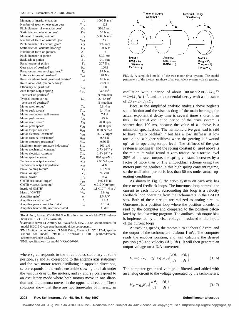
One potential problem with this system is that the mtors and the antenna, considered as three bodies, will olate with respect to each other through the springiness ofgears. Consider the model of the system shown in Fig. 5.moment of inertia and damping of the telescope are evated as reflected through the gearing, and static frictioignored. The equations of motion of the system are
J0d2u0dt2
52k1~u02u1!2k2~u02u1!2D0
du0dt
, ~3.1!
J1d2u1dt2
52k1~u12u0!2D1
du1dt
1T1 , ~3.2!
J2d2u2dt2
52k2~u22u0!2D2
du2dt
1T2 . ~3.3!
The antenna position variableu0 will exhibit a variety ofbehaviors depending on the time history of the torques inby the motors,T1 andT2 . The generalized response ofu0 toinput torques can be approached through the transfer ftion relatingu0 to T1 andT2 . Take the Laplace transform11
of Eqs.~3.1!, ~3.2!, and~3.3!:
J0s2u0~s!1k1u0~s!2k1u1~s!1k2u0~s!2k2u2~s!
1D0su0~s!50, ~3.4!
J1s2u1~s!1k1u1~s!2k1u0~s!1D1su1~s!5T1~s!,
~3.5!
J2s2u2~s!1k2u2~s!2k2u0~s!1D2su2~s!5T2~s!.
~3.6!
Rev. Sci. Instrum., Vol. 68, No. 5, May 1997
Downloaded¬01¬Aug¬2007¬to¬128.103.60.225.¬Redistribution¬subject
-il-eeu-is
ut
c-
Define three quadratic function ofs:
Q0[J0s21D0s1k11k2 , ~3.7!
Q1[J1s21D1s1k1 , ~3.8!
Q2[J2s21D2s1k2 . ~3.9!
Rearranging terms to eliminateu1(s) and u2(s) yields thetransfer equation:
u0~s!5k1Q2T11k2Q1T2
Q0Q1Q22k12Q22k2
2Q1.
The behavior of this function is governed by its poles, whiare roots of the denominator. Since the GMTB sets aresentially identical, takek15k2 andQ1(s)5Q2(s), and thissixth order polynomial becomes factorable and analyticasolvable. Taking worst-case values ofk15KmG/NG
2
5790 N m/radian, D150.175 N m/radian/s, D050, J150.175 N m s2, and J050.735 N m s2, the poles of thetransfer function are
s150, ~3.10!
s25~20.080110.7i ! Hz, ~3.11!
s35~20.080210.7i ! Hz, ~3.12!
s4520.051 Hz, ~3.13!
s55~20.054113.0i ! Hz, ~3.14!
s55~20.054213.0i ! Hz, ~3.15!
2207Submillimeter telescope
¬to¬AIP¬license¬or¬copyright,¬see¬http://rsi.aip.org/rsi/copyright.jsp
mrsd
ece: a
le
ctsthehanis
aidwndar
elby atwoime,op-
hastheityTBits.r islcu-biasuts
ndterired
ithters:
for
fi-or/
elring.
wheres1 corresponds to the three bodies stationary at soposition,s2 ands3 correspond to the antenna axis stationaand the two motor rotors oscillating in opposite directions4 corresponds to the entire ensemble slowing to a halt unthe viscous drag of the motors, ands5 ands6 correspond toan oscillatory mode where both motors move in one dirtion and the antenna moves in the opposite direction. Thsolutions show that there are two timescales of interest
TABLE V. Parameters of AST/RO drives.
Moment of inertia, elevation JE 1000 N m s2
Number of teeth on elevation gear NGE 122Pitch diameter of elevation geara DE 516.5 mmStatic friction, elevation geara TfE 50 N mMoment of inertia, azimuth JA 5000 N m s2
Number of teeth on azimuth gear NGA 236Pitch diameter of azimuth geara DA 999 mmStatic friction, azimuth bearinga TfA 100 N mNumber of teeth on pinions NP 14Pitch diameter of pinion DP 59.3 mmBacklash at pinion BP 0.1 mmRated torque of pinion TP 207 N mGear ratio of gearheadb NG 100:1Rated output torque of gearheadb TG 87 N mUltimate torque of gearheadb TuG 178 N mRated overhung load, gearhead bearingc LG 80 N mRated axial load, pinion bearingc 2224 NEfficiency of gearheadb EG 0.8Zero-torque output springconstant of gearheadb
KmG 43103
N m/radianTypical output springconstant of gearheadb
KG 2.443104
N m/radianMotor rated torquec TM 0.6 N mMotor peak torquec TuM 6.4 N mMotor continuous stall currentc I M 7.4 AMotor peak currentc I uM 79 AMotor rated speedc VM 2000 rpmMotor peak speedc VuM 4000 rpmMotor torque constantc KtM 0.08 N m/AMotor electrical constantc KeM 8.8 V/krpmMotor terminal resistancec RtM 0.84VMotor armature resistancec RaM 0.66VMaximum motor armature inductancec LaM 100mHMotor mechanical constantc TmM 2.731023 sMotor electrical constantc TeM 1.431024 sMotor speed constantc KsM 890 rpm/N mTachometer output constantc KeT 2.00 V/krpmTachometer output impedancec R0T 4 VBrake holding torquec TB 0.9 N mBrake voltagec VB 24 VDCBrake powerc PB 9 WGMTB frictional torquec TfM 0.024 N mGMTB viscous dampingc KdM 0.012 N m/krpmInertia of GMTBc JM 1.131024 N m s2
Mass of GMTBc WM 6.8 kgAmplifier gaind ga 1.6 A/VAmplifier rated currentd I a 68 AAmplifier peak current for 0.4 sd I ua 616 AAmplifier bandwidth, uncompensated 1 kHz
aRotek, Inc.; Aurora, OH 44202 Specifications for models A8-17E21~eleva-tion! and R8-35EXX2~azimuth!.bHarmonic drive; 51 Armory St., Wakefield, MA, 01880; specificationsmodel HDC 5 C cup-type harmonic drive components.cPMI Motion Technologies; 39 Mall Drive, Commack, NY 11724; specications for model S9M4HI/BRK/S9A4T/H9D-100 gearhead/mottachometer/brake package.dPMI; specifications for model VXA-38-8-16.
2208 Rev. Sci. Instrum., Vol. 68, No. 5, May 1997
Downloaded¬01¬Aug¬2007¬to¬128.103.60.225.¬Redistribution¬subject
ey,er
-sen
oscillation with a period of about 100 ms'2p(J0 /k1)1/2
'2p(J1 /k1)1/2, and an exponential decay with a timesca
of 20 s'2pJ0 /D1 .Because the simplified analytic analysis above negle
static friction and the viscous drag of the main bearings,actual exponential decay time is several times shorter tthis. The actual oscillation period of the drive systemshorter than 100 ms, because the value ofk1 above is aminimum specification. The harmonic drive gearhead is sto have ‘‘zero backlash,’’ but has a low stiffness at lotorque and a higher stiffness when the gearing is ‘‘wouup’’ at its operating torque level. The stiffness of the gesystem is nonlinear, and the spring constantk1 used above isthe minimum value found at zero torque. At a torque lev20% of the rated torque, the spring constant increasesfactor of more than 5. The antibacklash scheme usingmotors puts the gearhead in this high spring constant regso the oscillation period is less than 50 ms under actualerating conditions.
As shown in Fig. 6, the servo system on each axisthree nested feedback loops. The innermost loop controlscurrent to each motor. Surrounding this loop is a velocfeedback loop operating from the tachometers in the GMsets. Both of these circuits are realized as analog circuOutermost is a position loop where the position encoderead by the computer and compared to the position calated by the observing program. The antibacklash torqueis implemented by an offset voltage introduced to the inpof the current loops.
At tracking speeds, the motors turn at about 0.3 rpm, athe output of the tachometers is about 1 mV. The compureads the encoder position, and will calculate the desposition (uc) and velocity (duc /dt). It will then generate anoutput voltage on a D/A converter:
Vc5gp~uc2u0!1gvKeTS ducdt
2du1dt D . ~3.16!
The computer generated voltage is filtered, and added wan analog circuit to the voltage generated by the tachome
Vd15gdKeTS du2dt
2du1dt D . ~3.17!
FIG. 5. A simplified model of the two-motor drive system. The modparameters of the motors are those of an equivalent system with no gea
Submillimeter telescope
¬to¬AIP¬license¬or¬copyright,¬see¬http://rsi.aip.org/rsi/copyright.jsp

FIG. 6. Schematic of the AST/RO servo system for one axis. Both axes are identical, aside from the servo tuning parameters.
ue
to
-
ric
hebla
tiohe
a
io
icgn
ersra-er-messfors.ting
wasingandhenTheand23ethesub-
theviderc-in. Onubheis
athethethed ato
The voltageVoff is a constant chosen to provide a torqoffset between the two motors:
Voff'0.2TM /~KtMga!50.9 V. ~3.18!
The combined voltage is input to the amplifier, and the moconnected to the amplifier will produce a torque
T15KtMga1Va12TfM . ~3.19!
Equations~3.16!, ~3.17!, and ~3.18!, and the correspondingequations for motor 2~with the subscripts 2 and 1 interchanged!, along with Eqs.~3.1!, ~3.2!, and ~3.3!, describe atracking servo. The gainsgp , gv , andgd must be chosen toensure stable operation.
The electronics shown in Fig. 6~except for the computeand GMTB sets!, plus interface logic, fuses, diagnostmeters, and manual controls are implemented in a singlein. high, standard 19 in. rack chassis, the ‘‘drive box.’’ Tdrive boxes for azimuth and elevation are interchangeaThree boxes were fabricated; one is a plug-compatible sp
B. Encoders
A shaft encoder is used on each axis, to provide posiinformation to the control computer which is used in tservo loop. Design criteria for the encoders are:
~1! one arcsecond or better resolution~21 bits!;~2! readout is absolute;~3! the assembled encoder is sufficiently rugged to rem
mounted and aligned during shipment;~4! the operating temperature is between140 and
270 °C;~5! encoders are identical for both azimuth and elevat
axes;~6! 120 mm or larger hole through center.
While there are commercially manufactured encoders whsatisfy these requirements, their price is an order of ma
Rev. Sci. Instrum., Vol. 68, No. 5, May 1997
Downloaded¬01¬Aug¬2007¬to¬128.103.60.225.¬Redistribution¬subject
r
10
e.re.
n
in
n
hi-
tude more than was allowed by the project budget. Encodwere therefore made in the instrument shop at Bell Labotories, using Inductosyn™ steel transducer plates, commcial preamplifiers, and one fully constrained 287-mm-diabearing per encoder. A mounting plate of magnetic stainlsteel was machined with pockets for lightening andmounting the preamplifiers and miniature ‘‘D’’ connectorOne of the transducer plates was screwed to this mounplate, aligned concentric with its outer diameter within 5mm,and the wires connected. The other transducer platemounted to the rotating part of the large-diameter bearwith a shim plate machined to the appropriate thickness,then aligned concentric to that bearing. The bearing was tscrewed to the stainless mounting plate, and aligned.resulting encoder consists almost entirely of steel parts,is quite rugged—in one test, it read out accurately withbits of precision while cold-soaked in a box full of dry icand repeatedly hit with a hammer. Star-pointing tests ontelescope indicate that the encoder is accurate at thearcsecond level.
One drawback of this encoder design is the;1 N mstarting torque of the encoder bearing. The mounting ofencoders to the telescope axes is heavy and stiff, to protorques sufficient to drive the encoder with less than an asecond of wind-up, while accommodating differencesrunout between the encoder bearing and the axis bearingthe elevation axis, the encoder mounts rigidly onto a hdirectly on the elevation shaft, and the outer body of tencoder is prevented from moving by a ball bearing whichspring loaded between a flat plate~the plane of which in-cludes the elevation axis! attached to the encoder body andparallel flat plate attached to the telescope structure. Onazimuth axis, a torque tube is needed to allow room forcable wrap. The azimuth encoder is screwed directly tosame structural plate which holds the azimuth bearing, an228-mm-diam, 10-mm-thick steel torque tube is mounted
2209Submillimeter telescope
¬to¬AIP¬license¬or¬copyright,¬see¬http://rsi.aip.org/rsi/copyright.jsp

The came position ofthe logic
FIG. 7. The limit-switch scheme for AST/RO. The cam is machined into the rotating part of the azimuth bearing mount. The switches do not rotate.and switches are shown for an azimuth of 180°, where the cam edges are presently at 55° and 305°. The angle associated with each switch is ththe cam edge when the switch is actuated. N.O.—normally open; N.C.—normally closed; H.C.—held closed; H.O.—held open. The wiring illustratesused to derive the limit signals; in practice, each switch is separately interfaced to the computer.
ets
letu
txigto
utnor
aannndibag
it
mitofenTheatesenamothherig.camtheheilln-. Ifthe-thee-ves
the inner part of the encoder bearing. The torque tubetends upward for a meter, so that the upper end is abovecable wrap, and a lever arm on the end of the tube holdball-bearing arrangement similar to the elevation axis.
C. Limit switches
Motion on the azimuth axis is limited by the cabwrap—the cables cannot be wound more than 270° of ain either direction ~540° total! without damage. Limitswitches are needed to prevent telescope motion beyondrange of travel. One complication is that the azimuth atravel is more than one turn, whereas the encoder is a sinturn type, bounded by 0° and 360°. Turning past 0°21° gives a reading of 359°, and turning past 359&99999 to361° gives a reading of 1°. The limit switches on the azimaxis must therefore allow more than one turn of travel, ashould allow an indication of angles less than 0° and mthan 360°~‘‘overtravel’’ !. The overtravel indication shouldbe dependent only on the state of the switches and not onexternal memory, so that the system can be turned offturned back on, or the axes moved with the power off, athe overtravel condition will always be correct. In additiothe limit switches should be robust and must work in contions of extreme cold. The limit switch scheme shouldfail-safe in the sense that no single failure results in dam
2210 Rev. Sci. Instrum., Vol. 68, No. 5, May 1997
Downloaded¬01¬Aug¬2007¬to¬128.103.60.225.¬Redistribution¬subject
x-hea
rn
hissle-
hde
nydd,-ee
to the telescope at the limits, and single failures of the limswitches are readily detectable.
The switches chosen are a standard industrial liswitch, unusual only in having a temperature rating265 °F. The switch is operated when its lever is overriddby a cam cut into the azimuth structure of the telescope.switch and lever can be set up so that the switch opereither when the cam approaches from the right only, whthe cam approaches from the left only, or when the capproaches from either direction. Each switch contains bnormally closed and normally open contacts, so altogetthere are six different modes of operation, as shown in F7. Suppose the switch is set up to operate when theapproaches from the left. The lever has a spring return tocenter ~vertical! position. If the cam overrides the switcfrom the left, the lever on the switch will rotate clockwisand the switch will operate—the normally open contact wclose and the normally closed contact will open. The cotacts remain this way until the lever is released by the camthe cam overrides the switch from the right, the lever onswitch will rotate counterclockwise, and the lever will remain depressed as long as it is beneath the cam, butswitch will not operate. This property provides th‘‘memory’’ which allows the ensemble of switches to remember how the antenna moved into position, and remothe ambiguity between e.g., 1° and 361°.
Submillimeter telescope
¬to¬AIP¬license¬or¬copyright,¬see¬http://rsi.aip.org/rsi/copyright.jsp

th0itc°
eeel.heowt
ofr
tth
atureea-ere.urce.azi-. 1.re-and90earky.amm
ma-Ec-m,ra-ur-ick:m-tion.led
loadtput
outodytheon-
Figure 7 shows the setup and wiring of the azimuswitches. The cam position is shown for an azimuth of 18The cam has an open sector of 110° in which the swlevers are not depressed, and a closed sector of 250which the levers are depressed~in operating or nonoperatingorientations!. The cam was milled into the 0.9-m-diam stesupport of the azimuth bearing. Four signals are produclimit, prelimit, positive overtravel, and negative overtravThe types of signal and the range of azimuth over which tare produced are shown in Table VI. Table VII shows hthese signals are generated by opening and closingswitches over various ranges of angles. Note that failuresingle switch might result in failure of either the prelimit olimit, but not both.
D. Calibration system
The calibration system measures the gain and offsethe receiver chain, and the atmospheric emission. From
TABLE VI. Signals produced by azimuth limit switches.
Signal Value Range Logic
limit 1V 465°.Az.250° ~SW11SW4!•~SW21SW9!open Az.465° or Az,250°
prelimit open 450°.Az.235° SW3•SW81SW10•SW5
1V Az.450 or Az,235°
positive open Az,359° SW3•SW7
overtravel 1V Az.359°
negative open Az.1° SW10•SW6
overtravel 1V Az,1°
Rev. Sci. Instrum., Vol. 68, No. 5, May 1997
Downloaded¬01¬Aug¬2007¬to¬128.103.60.225.¬Redistribution¬subject
°.hin
ld:
y
hea
ofis
recorded spectra can be converted from antenna temperto the equivalent antenna temperature that would be msured by an ideal telescope above the Earth’s atmosphThe calibration system is also used as a chopped sowhen tuning the receiver for minimum noise temperature
The calibration system is suspended underneath themuth structure above the receiver table, as seen in FigThree blackbody calibration loads can be viewed by theceivers: a load at the receiver room ambient temperaturetwo loads cooled by a closed cycle refrigerator to 40 andK. The ambient temperature load is mounted on a linactuator and can be moved to block the beam from the sThe cooled loads are in a Dewar to the side of the becoming into the Coude´ room and are switched into the beaby flat chopper mirrors.
The loads are made from precast Eccosorb CR-110chined into wedge shaped strips and glued together withcosorb CR-110 resin. The back of the load is aluminuwhich provides the thermal conducting path to the refrigetor. Eccosorb CR-110 has low absorption but also low sface reflection. Because of this, the loads are relatively th3 cm from front to back. This guarantees that at low teperature and low frequency, when the Eccosorb attenuadecreases, the absorption ofl1.2 mm radiation exceeds 0.99
The measured blackbody temperatures of the coocalibration loads is not as low as expected.~Load blackbodytemperatures where measured by comparing them to asoaked in liquid nitrogen and assume that the receiver oupower was linear in antenna temperature.! The load on the 40K refrigerator stage has a blackbody temperature of ab100 K and the load on the 90 K stage has a 140 K blackbtemperature. This is due to infrared radiation warmingsurface of the loads, which have relatively poor thermal c
TABLE VII. Azimuth limit switch truth table. O5open, I5closed, 0 indicates open circuit,1indicates1V.
Azimuthangle range
Switch Signal
1 2 3 4 5 6 7 8 9 10 limit prelimit 1O.T. 2O.T.
,250 O I O O I I O O I I 0 1 0 1
250,235 O I O I I I O O I I 1 1 0 1
235,21 O I O I O I O O I I 1 0 0 1
21,11 O I O I O I I O I I 1 0 0 1
11,90 O I O I O O I O I I 1 0 0 090,105 O I O I O O I I I I 1 0 0 0105,109 O I O I O O I I O I 1 0 0 0109,123 O I O I O O O I O I 1 0 0 0123,139 O I O I O O O I O O 1 0 0 0139,200 I I O I O O O I O O 1 0 0 0200,215 I I O O O O O O O O 1 0 0 0215,251 I I O O I O O O I O 1 0 0 0251,261 I I O O I I O O I O 1 0 0 0261,277 I O O O I I O O I O 1 0 0 0277,310 I O I O I I O O I O 1 0 0 0310,325 I O I I I I O O I O 1 0 0 0325,359 I O I I O I O O I O 1 0 0 0359,361 I O I I O I I O I O 1 0 1 0361,450 I O I I O O I O I O 1 0 1 0450,465 I O I I O O I I I O 1 1 1 0.465 I O I I O O I I O O 0 1 1 0
2211Submillimeter telescope
¬to¬AIP¬license¬or¬copyright,¬see¬http://rsi.aip.org/rsi/copyright.jsp

roaadeast
99he3f-terialsoey’nicaic
io
binresthth
m
tere
e;K
he
rtosty
eHorifie
ga-e
u-riveROden,de-ni-llllo,lmre-un-a
Re-.
.lly,J.
Na-ofnd
theele-
ductivity. The radiation temperatures of the loads are thefore calibrated manually about once a month against a limmersed in liquid nitrogen, and thermometers on the loare monitored during observations. This calibration systhas worked well in practice, giving reproducible resultsthe 5% level on repeatative measurements of standard anomical sources over the course of more than a year.
IV. OPERATIONAL STATUS
The AST/RO telescope was fabricated between 1and 1992 at Bell Laboratories, Crawford Hill, NJ, and at tScientific Instrument Facility at Boston University. In 199and 1994, it was installed at a test site in Boston and usedobservational tests.1 In August 1994, this entire working observatory was packed into crates and shipped. Unfortunathe truck carrying all the equipment was involved in a seous accident. Some of the parts which had been criticpositioned in the shop during telescope assembly, such aencoders, were knocked out of position. When mountedthe AST/RO building at the Pole, the telescope can beclosed in a retractable cloth and aluminum ‘‘baby-buggcover. This sheltered working environment allowed an uplanned partial disassembly and realignment of the critcomponents, demonstrating that even delicate mechanwork can be accomplished on the Polar plateau.
The operational telescope meets all design specificatfor observations at 600mm wavelength, except for pointingerrors. Operations at shorter wavelengths are plannedhave not yet been undertaken. The pointing model and poing techniques are still under development; the largestmaining problem is;20 arc sec variations in the tilt of thtelescope pier. The following error of the drive system is lethan 1 arc sec. The main beam efficiency, which relatespower scale at the receiver to the power scale withinmain beam~the product ofh l andh f in the notation of Ulichand Haas!,12 exceeds 80% at wavelengths between 1.3 mand 600mm.
Currently, there are four heterodyne receivers mounon an optical table suspended from the telescope structuthe spacious, warm Coude´ room:
~1! a 230 GHz SIS receiver, 500 K SSB noise temperatur13
~2! a 460–500 GHz Schottky-barrier diode receiver, 950DSB ~this receiver will work without a liquid Heliumsupply!;14
~3! a 492 GHz SIS waveguide receiver, 340 K DSB with tcurrent SIS junction;15
~4! a 492 GHz SIS quasioptical receiver, 170 K DSB.16,17
The laboratory space under the telescope holds thracks of electronics, including two 1.2-GHz wide acousoptical spectrometers and one high-resolution acouoptical spectrometer,18 cryogenic equipment, laboratorbenches, and storage for tools.
The first observations from the South Pole were madJanuary 1995. Figure 8 shows a spectrum of the 492 Gline of neutral atomic carbon toward the Galactic Center mlecular cloud Sagittarius A taken by AST/RO. As of Janua1996, AST/RO completed a year of operations. No signcant equipment problems occurred. Over 110 000 raw sp
2212 Rev. Sci. Instrum., Vol. 68, No. 5, May 1997
Downloaded¬01¬Aug¬2007¬to¬128.103.60.225.¬Redistribution¬subject
e-dsmtro-
0
or
ly,-lythenn-’-lal
ns
utt-e-
see
din
ee-o-
inz-y-c-
tra were obtained, including maps of strips through thelactic plane in the 492 GHz line of CI, and detection of somvery weak lines (0.2 K km s21) from the Magellanic clouds.
ACKNOWLEDGMENTS
The authors would like to thank Dennis Mumma, Mareen Savage, and Edgar Castro for their work on the dsystem. We thank Joe Rottman for the design of the AST/building and pier, and John Bally for the design of the Cou´room optical table supports. We thank Robert W. WilsoJohn Bally, and Dennis Mumma for discussions on thesign of the antenna. We thank the staff of the Boston Uversity Scientific Instrument Facility and the staff of the BeLaboratories Crawford Hill shop, especially George PisieAl Smith, and Karl Schwarz. They also thank Simon Baand Adair Lane for help with telescope assembly. Thissearch was supported in part by the National Science Fodation ~NSF! under Grant No. OPP88-18384 and undercooperative agreement with the Center for Astrophysicalsearch in Antarctica~CARA!, Grant No. NSF OPP89-20223CARA is an NSF Science and Technology Center.
1A. A. Stark, A. P. Lane, S. Balm, M. Rumitz, T. Bania, R. Chamberlin, MHuang, J. Ingalls, J. Jackson, E. Castro, G. Engargiola, K.-Y. Lo, J. BaR. W. Wilson, G. Wright, D. Mumma, R. Schieder, J. Stutzki, andStaguhn, Antarctic J. U. S.XXIX , 344 ~1994!.
2AST/RO is the result of a successful proposal to the United Statestional Science Foundation by A. A. Stark, J. Bally, and R. W. WilsonBell Laboratories, T. M. Bania and A. P. Lane of Boston University, aK.-Y. Lo of the University of Illinois.
3J. Bally, in Astrophysics in Antarctica, edited by D. J. Mullan, M. A.Pomerantz, and T. Stanev~AIP, New York, 1989!, p. 100.
4R. A. Chamberlin, A. P. Lane, and A. A. Stark, Astrophys. J.476, 428~1997!.
5W. Schwerdtfeger,Weather and Climate of the Antarctic~Elsevier, NewYork, 1984!, pp. 26–62.
6T. S. Chu, IEEE Trans. Antennas Propag.AP-31, 614 ~1983!.7C. Dragone, IEEE Trans. Antennas Propag.AP-30, 331 ~1982!.8D. J. Schroeder,Astronomical Optics~Academic, San Diego, 1987!, p.101.
9P. F. Goldsmith, inInfrared and Millimeter Waves, edited by K. J. Button~Academic, New York, 1982!, p. 277.
FIG. 8. The 492 GHz line of neutral atomic carbon, in the direction ofGalactic Center molecular cloud Sagittarius A, taken by the AST/RO tscope from the South Pole.
Submillimeter telescope
¬to¬AIP¬license¬or¬copyright,¬see¬http://rsi.aip.org/rsi/copyright.jsp

ch.
10Fabricated by Dornier GmbH, Friedrichshafen, Germany.11R. N. Bracewell,Fourier Transform and Its Applications~McGraw-Hill,New York, 1965!, pp. 219–240.
12B. L. Ulich and R. W. Haas, Astrophys. J. Suppl. Series30, 247 ~1976!.13This receiver was made in 1989 at Bell Laboratories by J. Bally.14Made by Radiometer Physics, GmbH, Meckenheim, Germany.
Rev. Sci. Instrum., Vol. 68, No. 5, May 1997
Downloaded¬01¬Aug¬2007¬to¬128.103.60.225.¬Redistribution¬subject
15Made at the University of Arizona by C. Walker.16G. Engargiola, J. Zmuidzinas, and K.-Y. Lo, Rev. Sci. Instrum.65, 1833
~1994!.17J. Zmuidzinas and H. G. LeDuc, IEEE Trans. Microwave Theory Te40, 1797~1993!.
18R. Schieder, V. Tolls, and G. Winnewisser, Exp. Astron.1, 101 ~1989!.
2213Submillimeter telescope
¬to¬AIP¬license¬or¬copyright,¬see¬http://rsi.aip.org/rsi/copyright.jsp