optical design for a head-mounted display - mcgill...
TRANSCRIPT

•
•
•
Optical Design for a Head-Mounted Display
by
Jiantao Ma
Il.S., Peking University, China (1987)
SUBMITTED TO
'l'lm FACULTY OF GRADUATE STUDIES AND RESEARCH
IN PARTIAL FULFILLMENT OF THE
REQUIREMENTS FOR THE
DEGREE OF
MAS'I'ER OF ENGINEEIHNG IN BIOMEDICAL ENGINEERING
DEPARTMENT OF BIOMEDICAL ENGINEERING
MCGILL UNIVERSITY, MONTREAL
November, 1992
@1992 by Jiantao Ma

•
•
•
Optical Design for a Head-Mounted Display
by
.Jiantao Ma
Suhrnitted to "hf' Faculty of Graduate Studies and Rosearch on November, 1992 in partial fulfillment of the
rcquirernC'nt!'; for the Degrf'e of M a. ... tN of F:ngineC'ring in Diorn~dieal Engineering
ABSTRACT
This tI)('sis rq>ürt.s on the design of 3n optical relay for u!'e in a color, stereo Head
Moulltl'(1 J)isplilY (11MB) system.
Bas"d on rf'vi('wh and discussions of the requirt'ments of the human visual system, major
fa(·tors il fI('('t.i IIg Hu' vislJfll i1cui ty, the aherration toterances of the h uman eye, and optical
dl'higll limit.at.iolls, w(' derive t.he d(~sign crit<'Tia for the optical rday. A survey of alternate
apprnadu'h to tlu' t./lf(·(' componellts of IIMDs is pl'esented .
A hri('f r('vi('w of firs!. ordN optics, aberration theory, general design principles, and
("olllIHltN ,Iid('d !t'IIS design is a.lso giv('n.
'l'wo mult.i-splu·rÎl'allt'ns sy1'itf'IllS, il st.raight structure and a folded Jayout, are presented.
"'Iu'i r al)(,lril t.iOllh (dist.ortion, coma, lat<'l'al color, field curvature an d astigmatism) have
1)('('11 W(·I! ('orr(·flpd. Ea.dl of th('m has a 20 mm eye relief and an instantaneous field-of-view
grpa!.pr thall HO" .
ii
•
•
•
RÉSUMÉ
Cette thèse décrie conceptuellement un système optique pouvant être utilisé dans un "Head
Mounted Display" couleur et stéréo.
Les critères de conception d'un système optique sont détenninés l panir de I~'vues ct de
discussions des exigences du système visuel humain, des facteures majeurs affectant l'acuité visuel.
des tolérances de l'oeil humain aux abérrations et des limites du système optique. Un invemaire des
approches alternatives au HMD l trois composantes est présenté.
Un court résumé d'optique du premier ordre, de la théorie des abérrations, des principes
généraux de conception et de la conception de lemme assistée par ontinateur est aussi présen~.
Deux systèmes l lentilles sphériques multiples sont présentés. Le premier a une structure
linéaire, le second, une structure pliœ. Leurs abc!rrations (distonion. coma, couleur latc!rale,
courbure de champ et astigmatisme) sont bien œrrigées et analysées. Les deux systèmes SOli plaœs
l20mm des yeux et possèdent des champs de vision instantanés de plus de (g .
iii

•
•
•
Acknowledgments
f would Iike to tIlitnk my thesis f,upervisor, Profcssor John M. Hollerbach, for ail the
sup(>rvisioJl, l'Jlcouragerncn t and pati(!flΠprovided throughout the course of this thesis.
Without 11Îf> ,,(fort, thi!> dissertation would haVfl been impossible. It has been a rewarding
,'xp,!ri,'nf'f' worki fig IIndf'r his guidance.
Nf'Xt f th,tnk Prof(~%or Jan W. Hunter for hi" valuable advice at the beginning of the
proj('( t and Dr. Ya/lgllling Xu for many discussions we had. Professor Jan W. IIunter
inil,iatNI HH' idf>a of huilding l.ll(! IIf!ad-Mounted Display.
My I.hanks also go to rny fellow students in our lab for the help and support and for
having mad,. ()\lr lah CL plcasant environment in which to work. 1 also thank Mr. Steve
KafilJli for /lis 1."lp in writing titis thesis.
1 a III illd .. hl.f'd to Illy wifc Hongya./I and my son Joshua. 1 thank Illy wife for her continued
ulld,'rst,tllding, ('lIcouragemcnt, and help.
Last, huI. not I('asl., 1 woulrl Iikc to tha.nk my parents, broUter and sister for having been
VNy suppofl.ive dllring t/I(> course of ail my studies.
This ffls('arch was support.ed by a Hydro-Quebec Fellowship .
iv
• Contents
1 Introduction 1
1.1 Statement of the Problems .. · ..... 2
1.2 Display or Image Source ..... · ..... ;, 1.2.1 Cathodc- Ray Tu hes ... · ..... ., 1.2.2 Liquid Cryst.al Displays
• • 1 •• .\
1.2.3 OUler Displays .. . . .. .... r, 1.2.4 The BLHMD Display · ....... r,
1.3 Combiners .... · ........ fi
• 1.4 Optieal Relays · ~ . . . . H
1.4.1 Eyepiecc or Magnifier .. . . . . . . . H
1.4.2 Objective-Eyepiece Structure JO
1.4.3 Flexible Fibcr Optics Bundle ....... JO
1.4.4 The BLHMD Optical Relay ...... \0
1 .1) HMD Systems. . .. . . . ............ " 1.5.1 Tilted Cat HMD .............. " 1.5.2 NASA EMU Holographie HMD ... \2
1.5.3 CAE Fiber Optic HMD · ..... \ :, 1.5.4 GEC NVG HMD . ... · ...... .. ...... 1 :J
1.5.5 Private Eye HMD . . . .. .... ....... \,1)
1.5.6 Summary and General Description of BlJIMI> Syst.f'1lI . I(i
1.6 Human Factors and Design Criteria ..... 1()
1.7 Contributions of the Thesis tH
1.8 Organization of the Thesis . ........ I!J
2 Lens Design Theory 20
2.1 Introduction . . . . 20 • 2.2 First arder Optics 21
v

•
•
•
3
2.2.1 Id(~al Optical Systprns ........ .
22.2 Carcll/laJ Points of an Optieal Syf>tem
2.2.:1 A SirrtpJI' LPT,f> Syl>tellJ ........ .
2.2A ('ornhill,tlion of IdNlI Optiea! Systems
2.2.1) llIlagp POf>ition and Size ..... .
2.2.n Lilllit?tionl> of Fir~1. Order Opties .
2.:1 AtH'" a Lion Th('ory . . . .
2.:U SI'IdpJ Alwrrat.ions
2.:1.2 (:11 romati( A h(\lTations
_.:1.:1 SlilIIIIJary .....
2.'1 COr!'('dlon of AI)('rrations
2A.1 "/liplu/in/.!; T(\('hnology"
2.'1.2 PPI,7,val SIIIlI and its Corr('ction
2.'1.:' L()( ,Ition of ApNture .
VIA Opl.ÎC'al Mat<~rialf. ...
2.;' CUlllplll.N Aid(·d Lells Design Optimization .
2J:i Condu~inns..... . ............ .
Optical Design Criteria and, Human Factors
:u IIl1l11a.n Eyp Cha racterist.ies
:1.1./ ( :l'n('ral . :1.1.2 Visual Aeuit.y
:1.1.:' Binonlla. vs. Monocular Vision.
:U A Wid(· 1 nstant.aneous Field of View
:1.1.5 Col or Vision
:J.I.ü S Il III III ary
:1.2 (;(,olll('try Fact.ors .
:1.2.1 Pllpil Sizl'
:1.2.2 Int('rpllpillary Distance (IPD) .
:1.2.:' EYl'I'l'li('f .
3.:1 AI)('rration 'J'o!Nances
:I.:U Ahl'rration 'lbleranres of Human Eye .
:J..I Optiral I)l'sign Crit('ria ............ .
4 Optical Design of HMD
·1.1 Introdlll'tioll ..... .
vi
21
21
24
26
27
27
28
35
36
36
37
37
38
39
39
42
43
43
43
45
47
50
50
50
51
51
52
52
53
53
57
59
59
•
•
•
4.2 History of BLH~ID Opti<ill th'la~' Ill'sign
4.3 Straight Design . . . .
4.3.1 Basic Struct ure of t Il<' Optiral Hplay
4.3.2 Fllrther ('ollsidNdtioni>.
4.3.3 Complltpr Optilllilatioll
4.3.4 Design Hcslllts dncl Analys('~
4.4 Foldpd Design. . .
4.5
4.4.1 Starting SystPIll
4.4.2 Design Proccd li rc .
4.4.3 Design Reslllts and Analysis .
"ummary
5 Conclusions
5.1 Summary
5.1.1 BLIIMD System
5.1.2 Design CritNia and Design Charart<'J'istÎ<'s
5.2 Limitations and Rerommcndations for FutuT<' H('~('ar('h
5.2.1 Structure of Optiral I(c1ays
5.2.2 Aberrations ... ..
vii
Iii
Ii:l
(i:1
li;;
il
il
i7
iH
HI
H:;

•
•
•
List of Figures
1.1 II(""I1·t.-Molllltpd Dihplay 'iybt('111 COIlC<'ptS. From [4J. . . . . . . . . . . . . . 2
1.1
I.a 1.'1
1':1
J.(i
1.7
I.X
1.1
1.1
~.:J
1.,1
v, 1.(;
.) ~ ~.I
1.~
Tilt(·d Caf. Syhl,('1II ill th(' Integrated Ilelrnet and Display Sighting System
(" 1 1\ DSS) . . .
NASA EMU Holop;I"I.phic ,,:vIf)
CAl,; rihN oplin HM\) .....
(;1';('\ lll'll'lIIt-MnllJlt .. d NVe System
OpIH .. 1 Ikhip;n of GEC'b IIPI(·II1t.Molllltcd NVG System
SdH·/IIat.lc of III(' Plival<' Eyp's dcsigll.
TIH' B LII ~IJ) byhtl'lIl. ....
ForaI pOlnlh ,IIHI prilldpal point.s
Nodal Poillth
A simpl(' 1('lIs
.,
Coaxial rolllhinat.ioll 01 1 \vo ideal optical systems.
IlIlaf.!,p pof,itioll and sizp rail ideal opt.icaJ system.
Spidpl A 1)('1'1',11 iOIl ..
Sph(') J( al AhPf) at.ioll
('0111 a .... . .
1.n TI\(· (,OIll,1 p,11 ch .
1.10 ,ht iglll,lt iSIIl
1.11 Fil'Id {'\trvat Il f'(' alld astigmatislll
1.11 Dbt ort iOIl . .
1.1:1 Lah·ral ('OlOf
;u lIorÎ/'olltal f,{'clion of th(' right. hutllan ('ye
11
12
13
14
14
15
17
22
23
23
25
26
28
30
31
31
32
33
34
3.5
44
:t1 'l'III' fmmat Ion on IIH' rpl i na of t.hl' image of a distan t point source of light. 44
;L;J Vis\I,ll aCllity as a fllllciion of background luminance . . . . 45
:t 1 \ïs\lal a!'lIity as a fllllctioll of t.argl'I distance froll1 fixation. 46
\'iii
•
•
•
3.5 l<kal vi('wing dbtallc(' ,Dioptrie f,(,ttillg. H('~ult~ frolll fi\"(, dIllt'I"!'lIt ~tlldi('~.)
From [12] ..
3.6 Binocular <lnd 1ll0nocIIlir ~(,II~lt I\'it~
3.7 AVNag(' lllonocnlai and hinorular p1lpd dlalll!'\N
3.8 ('omfort IlIlIit~ of !'~'I' rot ,II 1011 ••••••••
3.9 'l'Il(' diclllH't!'r J) of thl' ('xit pll(lil of ,1 1Ii\\D o,ltieall!'I,I.\'
·l.t L('n~ d('~igll flow rh,lrt Froll\ [17] ..... .
4.2 The first d('!.ip,n of the' BLIli\\D npti(,d fl'I,IY.
4.3 Aherratioll analy!.!',> of th" firi'lt opt 1(,,\1 1'1'1"y,
4.'1 Optieal relay illlproH'd fl01ll tll!' fjr~1 dpf,ip,l\.
4.5 Aherration <ln,llyf,pf, of th!' IIIIPIO\,('t! fili'll o(ltw." 1I'I,lY d('SI/.',11.
4.6 Th(' lop,btin pl'ObIPIII \VIt h WI!IP 1 FOV ('Vl'pl('e('~ ." ..
4.7 The starting ~yt.t(,1II of th" IILlli\lI) i'ltldip,ht oJllie,d d(·~i/-';II.
4.8 The aberratio/l an,lIyfol'~ of thl' t.taltill/!, foyt.tl'III of lIt(' ~lr,lÎ/!,ht "Jllw.1I dl't.i/!,II.
4.9 The Y-Z layo'lt ofthp optilllil.pd t.11"il!:ht Ilpll!'.d 11'1,IV.
4.10 The alH'rratioll cI/l,II.v'f,('f, of th(' oplilllil.pd fot r,lÎ/.',hl oplical dpt.il!.ll.
4.11 The IclYOllt of tl\(' fltarti/lp, ohj!'( ti\'(' of Ihl' loldl'd opli( ,II l'f'IdY.
'1.l2 The i>taltilll!: r-,yi>t'-'lIllayollt oftll(' foldpd opl.icaill'Iay dpt.I/.',II.
4.13 The layout of the oJltirllizpd foldpd o(lti(.11 Il'lay
,1.14 Th(' aherratio/l analyr-,(,i> of th!' optillliz('(1 foldpt! opti( ,II dl':,i/!,Il.
,5.1 Th(' optiral fih('r 1('1Ir-, tn flat.tl'n t.h(' fj('ld-of-vil'w. From [:W] . ..
ix
I~
I!l
.ri 1
i .,) ,)~
fi:I
fil
( ili
(i7
7,1
7(i
7!1
xo
X7

• List of Tables
2.1 Variation of aberrations with aperture and image height. . . . . . . . . . .. 36
a.J 'nterpupillary distance for ditrerent groups, based on observations taken from
military personnel. From [31. .. . . . . . . . . . . . . . . . . • . . . . . .. 54
3.2 Visual aberration values that could be discriminated in high contrast targets
a.t, 75% probability levels. From [61. . . . . . . . . . . . . 56
4.1 Structural parameters of the first BLIIMO optical relay. 61
4.2 Strurtural parameters of the starting system of the BLHMO straight optical
• relay. . . . . . . . . . . . . . . . . . . . . . . . . . . . . . . . . . . . . . . .. 68
4.3 Merit f\luction of the s1.arting system of the BLHMD stralght optical relay. 70
4,4 Merit fundion of the optimizt'd 8LHMO straight optical relay. .... . .. 72
4.5 Structural parameters of the optilllized BLHMD straight optical relay. . .. 73
4.6 Structural parameters of the objective of the BLHMD starting folded opticaJ
r(llay. . . . . . . . . . . . . . . . . . . . . . . . . . . . . . . . . . . . . . 76
4.7 Structuralilarameters of the optimized BLHMD folded optical relay. . 83
5.1 Summary of the design criteria and the characteristics of the two optical re-
lays. TFC is tht' tangentia,1 field curvature. SFC is the sagittal field curvature. 85
• x
•
•
•
Chapter 1
Introduction
This thesis reports on the progress in developing a color, st('reo Head-Mollllt.c'cI I>isplay
(HMD) system, especially the design of an opticaJ r('lay hc,tw('cn displ'lYs alld 0J,('mt.f)r's
eyes, at the Bioroboties Laboratory of McGill University.
A remote vision system is required for teleopcration in inaff('ssihl(' ('IIVÎrolllllC'IIt.S. 'l'II<'
partieular tele-microbotics research at the fJiorobotks tahoratory Îlldin,t,('s ft IU'f'd fnr iL
vision system which magnifies images sent bya robot Ol)erating IIlId('r a. dOSf~d ('II vironnU'ul.a.1
shield. Similarly, a visual display is also neressary for mÎe:rosllrgÏfill rohot.s t.n J)(~rforltl
human-guided ret!nal surgery and for endoscopie surgcry. At a. rna.crorohot.k Ic'vt'l, il vi""i,1
display would he useful for teleoperation in space, IIndersea.'i, in 1111C"1('ar Jlow('r plall •. Ii, and
for remote power line maintenance. A head-mollntcd display syst.f'ln was dc'sigm'cI for uS(,
in these tasks.
A OMO is a device attached to an operator's head or '1CIrrwt. tllilt. produ('('s il. viJ't.ual
image display for the operator. The device typically fOnsists of thr('(' suhsys •. C'lIIs, il clisJtlay
or an image source, a relay opties, and a combiner. Of tell a. Il M J) is uSNI in ffJlljulH't.inll
with another device, called a head-mounted sight (HMS) or head-sight, SYStf'lII (II SS), whÎC'h
is capable of determining the line of sight of the oJlcrator's h('acl alld C'OlIt.rollillg Sf'nsnrs'
orientations in the remote system so that thcy point in th(' same! dir('ftion as the nJtNal.or's
head. Thus the sensors are cou pied to the orien tation of the heacl, and tllf' i rnag.· prof! lu'('fI
by the sensors are displayed Cor the operator on the Il M D, formillg a dOSf!cI Iflop sysf.f'JII.
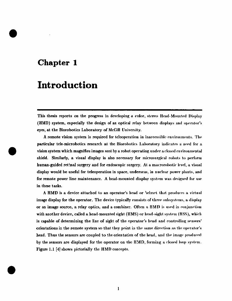
Figure 1.1 [4] shows pictorially the IIMD concepts .
1
•
•
•
Control Path
Hclmet
Operator Controlled
Helmet
......... _- Feedback Path
Figure 1.1: Helmet-Mounted Display system concepts. From (4).
1.1 Statement of the Problems
"MDs are olten as80ciated with the military, but recently HMDs have been .lied in teter
oboties [16]. Developing a "MD system (or telemanipulation is motivated by the (oUowing
(acts.
• If MDI provide operators a quick KcelS to important information from variOUI len80n
in the system, and the remote Icene as weU. This helpl the operator guide the robot
weil.
• HMDI use extremely sroall displays to supply the humo operators with panoramic
views covering a very wide viewing angle o( the remote scene, which is hard to achieve
witb conventional fixed (desk-top or panel-mounted) displays. This gives the h'lman
operator telepresence, the (eeling of being physically present at the remote site during
the performance o( telemanipulation.
• A HMD in conjunction with a graphies processor is an essential component in achiev
ing virtual reality, such as in a ftight simulator.
Although considerable effort has been expended in developing commercial HMDs, the
produds (ail into one o( two categories: very good but very expensive, or inexpensive but not
very good. We hope to deve10p an advanced HMD by a judicious mix between commercial
components and our own devetopments.
2
•
•
•
The eventual goal of this HMD projert is to design and ronstrurl, a stt'fI'O, ('olor visioll
HMD system (Biorobotics Laboratory IIMD or BLIIMD sysh'lI1) wilh a widc' instélllla.IH'OIIS
field of view (IFOV), and with compl'Ilsatioll for the opl'rat.or's IH'ael ,11111 ('~'" motion. TI ...
first key component that has 1.0 he d .. signed is a wid .. IFOV 0lltifal rl'Iay.
The wide IFOV is vital for "MDs t.o achieve a rc'alistÎf Sl'nsatinn (lf 1 .. lqm's('lIfI', and 10
enhance safety and efficiency. Decause the optic relay d('t.('rmin .. s IIH' (Illality nf illla~('s Im'
sented to operators, the a.berrations of the optical rl'Iay shollid h(' wI'1I fOrfl'('II'cl. Mon'ovl'r,
because HMDs have been investigated as a possible means of man-llIill·hinl' int .... fill'(" IIIt'
design criteria of the optical relay comes mainly from hlllllêln f.u·tors n'Ilui fI'lIH'n 1 s, 11('11(,('
careful consideration of human factors must he mad .. in Sl)('('ifyin~ 1 IH' dl'si~n nih'ria 1.0
ensure the operational utility of IIMDs for a partÎflllar applifat.ion. Th., main nh.~'l'I.iVl's of
this thesis are:
1. to derive optical design criteria by considering human fact.ors alld opl.il'al ('onstrailll,sj
and
2. to design dn optical relay for use in the BLHMD syst,('m, whirh has a IFOV gr('i\.I,I'r
than 60°, well-correctcd aberrations, while satisfying hlll1lan fal'l.or ('OllstriIÎnts lU1I1
optical constraints.
The following three sections review the typical mmpoll('nts of hoth s(,I·-t.hrnllp;h and non
see-through HMDs, in order to give a dearer vicw of ('aI:h wmpollcllt's fUliftions, rl'Iativf'
advantages and disadvantages of various approal'hes, and tlH' dlOi('(' of 1'0111 pOli l'II 1.1' for t.h(l
BLHMD.
In Section 1.5 several existing "MD sy:,tems an' introducf'd 1.0 giv.· a full pid.Uf" of
applications and of alternate approaches towards Il M Ds, illduclinp; our ilL Il M n. TI ... d,'sip;1I
criteria of the optical relay and human factors criteria ar(' disnlss('d ill SI'I·tioll 1.'). Th(,
contributions and the organization of the thesis are presentcd in S"I'lion 1.7 and SC'l'tion 1./01
respecti vely.
1.2 Display or Image Source
Video displa,ys con ven a camera (or similar device) generatcd rf!pn·s('"tat.ioll of a !iff"'"
into a two dimensional i;nage that can be vicwed by human eyps. The rol"f-> of dÎl'I,!;tYf->
in see-through and non-see-through MMDs are different. A dif->play of a IIOII-f'>.,,·-t,hrough
HMD presents an image which is an external world f,cene superimposI'IJ with flllothf'f illlag"
providing sorne useful information frorn various sensors (rall(!d th.· inforrnatioll irnap;f'). Hut.
a display in a see-through HMD only serves ab an image sourI:(! which showf, HIf' iflformat.iofl
3

•
•
•
from various sensors and whosc image is superimposed with the real world scene by a
romhi,wr. Thf' id(!al display for use in IIMDs should have the following attributes:
• small display size hut high resolution,
• hmall volume and light weight,
• full mlor, ad('(,uatc lu minaflce and hip;!' .ontrast,
• fast r('sprJnhC,
• low operating voltage for safnl' 'sideration, low power consumption, and
• low (:ost.
1.2.1 Cathode-Ray Tubes
Of ail d(·vÏf'(·s thal. hav(' heen tri<>d <u: IIMD displays or images sources, th( cathode-ray
tuhe (eUT) il> hy far tll~ most versatiJe and the most capable of producing a high quality
imag(·.
Cll')'s hav(' high resolution (spot size can be sm aller than 0.5 square mm), fast response
(the artuaJ sp('('d of a CUl' is limited by the electronics that drive it [22, page 99]), the widest
vi('wing angle of any two dimensional electronic display devices, and very wide operating
teml)('raturl' rang .. (from -50°C to 100°C). ft can provide high brightness at the cost of
f(·duced resollltioJl. USllally CRTs are massive, bulky, have high power consumption, and
rC(luir(' clriving voltages as high as 20 kV. The resolution of color CRTs is lower than that
of monorhroml' CIlTs, sinre one color pixel consists of three primary color pixels (red, blue,
and gf(·(lfl).
AJlol.her important reason why most CRTs in see-through HMDs are monochrome is
that rombiners lI('l'cI monochrome clisplays whose primary wavelength falls into a narrow
w_wl'I('ngth r(·gion in which combiners have a high reflection coefficient. By tbis wave
Imlgth ma,trh, rombinl'rs ran have a high transmittance of an external worM scene in all
wav('lengths except this very narrow region while still maintaining a high reflection of a
monOdlrOIll(' in formation image.
1.2.2 Liquid Crystal Displays
Liquid cryst.al disl)lays (tCDs) are light modifiers (modifying eithe!' externallight or back
light), Ilot light. producers. The reftectance or transmittance of a liquid crystal changes
wh(,11 ail l'I('ctric fi('ld is aPI)lied.
As f1at-paJl('1 displays. LCDs are superior to CRTs in
4

•
•
•
1. volume (LCDs are very thin),
2. weight,
3. power consumption (several tens of JtW/cm2 ), and
4. operation voltage (only 2 to 5 V).
LCD resolution is increasing at a very rapid rat(', from 528 pixds I)('r s(lllar(' cm ill UU'
early 1980's to 4039 pixels per square cm three y('ars ago. Th('se lau('r Lens had rf'solutiolls
four times greater than CaTs in television service today. Now, a ('ollllll('rdai Thin-Film
Transister (TFT) active matrix LCD (2.7 inch diagonal Sony Wa.t.chman) has t.11f' 1>iUlJ(' \,ix(,1
size, 86,400 pixels in an area of 22.57 squar(' cm. In fact, i('solut.ioll is 110 IOIl~f'f a \,roh!.'m
for LeDs. The best LeDs can rival or surpass good-(Iualit.y enT:. wh"11 HIf' vi('will~ illlp;lt,
is zero. The drawbacks are slow response and small('r vÎf'win~ ilngh's. TIH' hi!!;h msl. of
LeDs has previously limited the application of Lens, hut t.h(' prif'(' is rilpidly d"('f('ilSill!!;.
The small viewing angle of LCDs is not a problem for us(' in Il M ns, sinn' t.h.' fllsplay is
always positioned at the zero viewing angle in HMDs, 'l'Il(' f"Luft' holds tI ... possihility nf
LeDs with higher resolution, and faster response .
1. 2.3 Other Displays
Light-emitting diode displays (LEDs) are usually uSf!d as symbol-only image SOllrft'S or as
status indicators in IIMDs due to their inherent low resolution and l)t)or full mlor Pt'f
formance. Advantages of LEDs are fast response, low pow('r con su rnJlt.Îon , low UpNil.t,ioll
voltage, light weight and small volume.
Miniaturization of the display and its support equipment. ha. .. madt' ft vacuum flUOf.'Sf"'II1.
display (VFD) attractive for less demanding applicat.ions. hs low rt'solution a.nd la('k of f .. 11
color capability limit its application in lIMDs, in spite of its many advalll.a.~('s, such a.s high
brightness, wide operation temperature, and low power consulllption.
1.2.4 The BLHMD Display
The BLHMD design is based on commercial color LeDs. The lengt,h of C nTs woul(1 ('ff'ah'
difficulties in the arrangement of optical relays and CIlTb, i.e., Clrrs art' usually pli 1. on HIf'
side of the opertor's head, not in front of the eyes. Th(! high op(!rat.Îon voltilgt· of CHTs
raises safety concerns. The weight of CRT is also a major prohlNn, LCDb not only far,
produce almost the same quality image as CIlTs within a small viewing anglt! abM)('iated
with HMDs, but also have the beneficial characteristics of bf!ing thin and liglttWf'ight whkh
.5
•
•
•
fa('i1itat.e optical design. We believe that the slow response of current J~COs will soon be
OVerfOm(!, and LCDs have the pof.ential of much higher resolution than CRTs. In fact, the
curr(mt ('Olor LCDb already have smaller pixel sizes than color CRTs, but the total available
J,ix(!1 Jlumber is not enough. Meanwhile the cost of LeOs has already come down in the
th(!sc two y('ars. For example, a Sony 2.7 inch Watchman cost $599 at the end of 1990, and
$27R six months later. lIased on these considerations, LCOs will soon be ideaJ for HMO
1IR(·.
1.3 Combiners
BOtll sf'C-I,hrough and non-see-through HMOs require combiners to superimpose an externaJ
worlcl s('('ne or image with information images from sensors. The design of combiners for
sce-through IIMOs is wlative simple compared to that for non-see-through HMOs. The
id(liLl cornhirwr shollld:
• !lot only provide high quaiity externaJ world image, but also a clear information color
image prop(!t1y overlapped on the external world image,
• be Iight weight, small and easy to install,
• combine th(' images in real time, and
• not limit the IFOV of HMDs.
The opt,ical combiner for non-see-through HMOs usually consists of simple beamsplit
t.ers which injl'd th(' information image into the primary external display image. This is
('spf'cially tru(' in a siflllliator or location where size and weight are of little importance.
neamSI)IiUer rombiners are simple but relative heavy if used in binocular HMOs, and don't
ha,ve mueh fI('xibility to control two overlapped images. Also this combiner requires a com
IIlicatcd and heavy optical relay, sinee two are needed, one for the external world image and
011<' for the int()rmation image.
Another novel approach, which is only possible when the digital image processing can ue
r('aliz('d in n-al t,ime, is a "rompu ter combiner". The advantages of this computer combiner
allproadl art':
1. bcUer control of image qllality in various application situations, such as daylight
vicwing or night v;ewing. ft is impossible for see-through HMDs to be used in both
(Iaylight and lIight vicwing .
2. imag<' siz<, élnd centering adjustment are controlledj
6
•
•
•
3. image comhining can he carried out "off head", th(,fC'by r('(llIrin~ tlU' wf'ight, of tilt'
HMD;
4. more fuuctions other than image combining can hl' pC'rforlll('d, i.f'" rhnosing difft'rt'nt,
information from various sensors to display, dlélllging working motl(·, and zoomin~ in
and out;
5. it provides a possible means of corrl'cting op tics aherrations in t rodlu'pd hy nl)tira!
relays.
The disadvantage of this approach is the requiremellt of pow('rflll vid('o prOf('ssors or
computers Lo implement the image processing task in r('al time, and nOIl-s('t·-t.hrollgh ('apa
hility. Today, computer technologies are growing so fast tha!. ('0111 JIll t.l'fS and vidf'(J pro('('SS(lrS
are becoming more and more powerflll and affordablc.
The design of a c"llllbiner with see-throllgh capability is whl'rf' IU'élrly ail t.tu· .. ffort.
lies. The combiner reflection and transmiUallce coefficients, whil'h .. n· proh<4 hly t.1H' IllUSt.
critical see-through HMD characteristic to be spedfied, fllndarncntally d"tt'rmilw UU' roLt,in
in luminance hetween the information image and the cxtern .. l world S('('IU', nélsi('ally t,wo
kinds of ter.hnologies, dichromatic coating and diffractive opties or hologra.l,hy, hav(' b('('11
applied to the design of see-through comhiners to control tll(' refleetivity or t.rilllsmissivit.y of
combiners. To improve the transmittance coefficient of thl' combillcr whil(· still III"illt,ainillg
a high reflection coefficient, both technologies "tuile" th(' fOlllhiner to havI' ,L high n·fI(·('f,int!
coefficient in only a narrow rangC' of wa.velengths encomp .. ssing t.he priHlary w",v(·I(·IH~t.h
of the information image display. ft is for t.his reason that. s('('-thfough Il M I>s IIS(' only
monochromatic CRTs.
Holographic combiners are superior to coating comhillefs henllls(! a gn'at,pr nllllll> .. r of
variables are available for correction of optical aberrat.ions. The major dfiLWtHu'k of hnlu·
graphie combiners is that multiple solutions of tlte diffrcu:tion e(llJatioll fIIay raus(' M'('OJJ(lary
images. Both coating and holographie combiners are angularly smlsit.ive.
In order to obtain a large IFOV white rctaining an aCfeptabl" ey<' f(lli"f (OU' dist.uu'(·
from the last surface of the optical system to the entrance p"pil of tilt' hUlllan (.y •. ), M!VNal
attempts have previously been made:
• optical power was added to a flat reftective combiner to redufc t.he Silol(' of t1w oh,j<·d.iVf!
lens for the same IFOV, and also extend eye relief [11 J. The additioll of J)()WN tu th.·
combiner introduces several optical abcrrations (c')ma, astigmat.isrn, and distort.ion)
whieh have to he corrected by a complex kns system .
• double- or multi-element combiners [34], and
7

•
•
•
Another point 1,0 (,()fI!;id(~r iH the particular IIMD application: daylight viewing or night
vi(·wing, Hin('(' thll(, two application situations d ":t,te the design of the combiner. It is
not pUHHihlf' tu optirnize one ol)tical combiner for" th day and night use. This is a major
drawhaf:k of ail optÏfal combin('rs.
Althol/gh optical rom biners have severa! drawbacks as indicated above, they are the only
dlOi('f~ for sf·,·-t,J.rollgh Il M Ds. The 8LHMD is intended for use in telerobotics, in which case
H,·('-through ahility iH of liUle importance, and an optical combiner is not neeessary. Sin ce
COlilputN ('omhiflNs have many advantages ovcr optical eombinNs, we employa computer
wmbirwr ill U)(' BUIMJ) system. Th(' design of relay opties now is simplified to the design
of ail t'y .. pi('(·(·.
A wlIlhirl('r ('1('111('111. may he thought of as a part of the optical relay which bring images
from the diHplay to th(' viewN's eyes. Hence, the design of both the see-through and non
Sf,(·-through fOlllhilU'rs musl. IJ~ considered with the design of optical relays.
1.4 Opticai Relays
A Il opt.i(·al rt'lay is uSllally called il "collimating lens" for see-through HMDs or an "eyepiece"
for 1I(1I1-s('(,-through HMlls. These two kinds of relay tenses have almost the same function:
to lIIi1k(· thl' imagl' from a display a,ppear as a virtuaJ image at infinity with respect to the
vil'wl'r. But. tll(' amlllg(,lllent of these optical relays is different. In see-through HMDs, the
optkôll n'Iay iH put hct,wcen t.he display and combiner such that the virtuaJ image formed
h.v n'Iay 1('IIS('8 is stlperiml)Osed by a combiner with an externaJ world scene al. infinity. In
(·ollt.rast.. lIon-8e('-through IIMDs uaually have opticaJ relays between the display and the
vÎf'WN'S ('Y('S S\lclt Olélt t.h(' virtual image of a superimposed display image is formed at
ill fillit.y.
Ali id('al opl,ies relay should
• I)f(wid(' as large ail IFOV as possible,
• hav(' Iittl .. or well-rorrect(·d aberrations, or if neces<;ary, deliberately introduce aber
mt.iolls 10 I\('gat(' aberrations introduced by other opties components such as the
('ombinl'r,
• satisfya.\l human cOllstraints,
• be ligh. wdgh', and
8
•
•
•
• safe.
Most design problems of the optkal relay arist' from 1 hl' f('qllif('III('lIt of a largt' IFOV,
because a large IFOV is formed by very obliquc Iight rays whkh {'allst' st'riolls aht'rralions.
The IFOV problem contains constraints su ch as tht' display is IIslIally 1)la('('<I dos(' 10 Il ...
optical relay, and the exit pupil of the opt,iral rt'Iay is fixNI ,II tl\(' lo('atinll ni Ih(' v Ït'W('f\,
eye. When a display is located near the optical f('lay, t II(' oh,~,('t.iv(' IlOi nI s 011 1 hl' lIlargi n of
the display are extra-off-axis points and will be poorly imagt'(1. 'l'II(' apNlllrt' of ail oplic-a.1
system coutrols the rays that pass through tht' system to form a imagt'. Tht' oplkal ! .. Iays of
HMDs with a fixed aperture location lose a very important IIll'éUlS of ('On 1 l'olling .tlwrrations.
1.4.1 Eyepiece or Magnifier
The most basic approach to the IIMD optical rt'Iay is a simpll' lIIagnifiN, or ('YI'pil'fl'. Th(,
structure of the eyepiece is simple if the re(l"ir('d \FOV is smalt, and is V('I'Y ('()mpl('x if
the IFOV is intended to be large while satisfying ail otll('r dl':-.ign ('l'iINi.l. An ('y"pi""t'
differs fundamentally from a photographie ohjective, whirh is also li positiv(' It'IIS, ill t.hal,
the entrance and exit pupils are olltside the system. 'l'hl' dialllt'h'rs of II'II:-'I's an' <lt't.Nlllilll'd
far more by the angular field to be covered than hy th(~ f('latiw ap('rtllf(' s .. 1. hy t.!u' displa)'
or by the objective lens. The larger the IFOV to lu' ('ov('I'{'d, t,11f largt'r I,h .. dialllf'ln of
lenses required.
The various approaches to this class of optiral rela,ys incltul(':
• multi-element spherical lenses providing mol'(' dpsign fret'dollls for "h(,rt'al.ioll mm'('
tion, and relatively large exit pupil a,nd long CYl' J'('lier fI 1, :lOJ;
• asphericallenses [11] or gradient illdt'x 1('lIses for alH'rmtiofl forrf'dioll;
• removal of sorne power from lenscs to cornhinpr to increasf' I,h(, WOV, 1,0 silllpli~v 1,114'
lens system, and to make the IIMD mo,'e compact [J 1];
• prisms as relay elemen ts to fold the whole optiral rt'Iay 1.0 f,av(' sJla('f~, and 1,0 ('orn'('1,
chromatic aberrations [24].
The eyepiece or magnifier approach is gencrally f,irnpl(' and r('lati\'('ly light., and J1f'1'lJIitf>
reasonably efficient transmission of the image from the display to th(' l'Y"~. 'l'hN'' 'J.f(' Imtfly
existing designs to choose as a starting point.
However, thi!. simple magnifier approa('hes has ft relatively small (,YI' relid, a small ,'xi ..
pupil, and a limitation on the maximum ad.ievable apparent IFOV. Mor(~ow'r, t!t"n! if, a
limitation 011 the size of display for hino('ular vif>ion.
9
•
•
•
1.4.2 Objective-Eyepiece Structure
Morf' ('omplf'x opt irai r!('sign aJ>J>roach(~s have becn constructcd [1.5]. These are characterized
hy illt.f~rrn(ldiat.f· illlaw' planl's, which th<.'n are re-imaged hy optical relays. Usually this kind
of opl.kaJ rl'lay cow,i!>l.s of two folding mirrors and two relay lenses (an objective and an
('Y('pi(l{'(~ ).
Thh; {)h.~~(·tiv(~-eycpip('l' structure approach has a number of benefits:
• 1.11(' display cali he mounted further from the eye, 50 the limitation on the size of
display is plimillated,
• I.h(· fPlltN of gravit y of HMD may be easily set,
• t,lll' ey(' r('li('f distallce can he made larger, and
• mort· df!sigll frepdom is available su ch that aberrations can be weil controlled.
\)isaclvitllt.itp;es illrllldc t.he addit.ion of more weight as a consequence of an additional
1('lIs sy!>I.NII (the objective), and 110 sec-through capability bccause no combiner is used.
Ohviously, this opt.ic<tl r(·lay is more complcx, and is more difficult to optimize .
1.4.3 Flexible Fiber Optics Bundle
Allof.h(·r approach t.o optical r('lay design is the use of a flexible fiber optics bundle (FFOB)
for I.rallsmittillg imag(ls on a. display to the operator [31]. This approach removes the display
wl'ight by lIIollllting t.he display off the operator's head. However, the size and flexibility of
th(' FFOn art· advNh<'ly afr('d('d as the resolution (determined by number of fibers) of the
hllll<lI(' is ill('f(·as('d. For this reaSOIl, the optimum use of this approach lies with applications
l'('(fuirinp; intNIII('diat(· n'solution levcls (40,000 to 150,000 elements). The cost of FFOBs
is a.iso a disadvalltage. Allother drawback is that two lenses are needed to couple images in
alld out. of HI<' FFOU.
1.4.4 The BI.HMD Optical Relay
Ou r ri rst. approadt 1.0 UI(' optical r(llay is an eyepiece consisting of multi-spherical lenses.
This syst,('1II has (t. wid(' instantan('ous FOV. well-corrected aberrations, and meets all the
dt'sigll nitNia. Sl'condly, a rolded d('sign, cOllsisting of a field lens system (objective), an
('Y(' I('IIS syst('1ll (l'y('pi('c('). dlld two folding mirrors, is considered as an alternative to the
fil'sl apl)roach .
10
•
•
•
12/2". S ••. , III
SCALr· .t
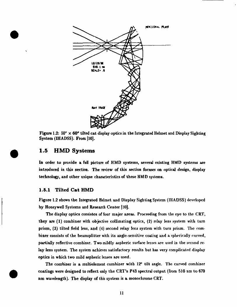
Figure 1.2: 50° x 60° tilted cat display optics in the Integrated Helmet and Display Sighting System (IHADSS). From [ID).
1.5 HMD Systems
In order to pro\'ide a fuU picture of HMD systems, several existing HMD systems are
introduced in this section. The review of this section focuses on optical design, display
technology, and other unique characteristics of these HMD systems.
1.5.1 Tilted Cat HMD
Figure 1.2 shows the Integrated Helmet and Display Sighting System (IIIADSS) developed
by HoneyweU Systems and Research Center [10].
The display optics consistes of four major areas. Proceeding from the eye to the CRT,
they are (1) combiner with objective colUmating optics, (2) relay lens system with turn
prism, (3) tilted field lens, and (4) second relay lens system with turo prism. The rom·
biner consists of the beamsplitter with its angle-sensitive coating and a sphNically curved,
partially reftective combiner. Two mildly aspheric surface lenses are used in the !j.!cond re
lay Jens system. The system achieves satisfactory reslllts but has very complicated disl)lay
optics in which two mild aspheric Icnses are used.
The combiner is a multielement combiner with l~ tilt angle. The curved combiner
coatings were designed to refleet only the CRT's P43 spectral output (from 510 nm to 670
nm wavelength). The display of tbis system is a monochrome CRT.
11

•
•
•
Upper Refledive liologrom
Lowe' Reflechve Hologrom
Wotchmon(tm) CRT
Figure 1.3: NASA Holographie HMD designed for the extra-vechicuJar mobility unit (EMU) on the Space Station Freedom, with head in viewing position. From [3Iff.
The system has a 10 mm diameter exit pupil, a rectangular field of view of 500 x 60°, 30
mm on-it.XÏs eye relief, and 18 mm eye clearance when measured from the plane of the exit
pUJiil tr, the lower edge of the beamsplitter. This gives an optimum eye position clearance
of 13 to 25 mm.
1.5.2 NASA EMU Holographie HMD
Figure 1.3 shows a holographie HMD developed by the Technology .Innovation Group
(TIG)/I.orkheed Engineering and Sciences Company (LESe) for the Crew and Thermol
Systems Division and NASA-Johnson Space Center (34). This HMD is unique in its use of
holographie optical elements (BOEs) on the helmet and protective visor surfaces to relay an
image from a CRT directly to the exit pupil. This HMD provides the user with a biocular
virtual image in a 25 degrees diagonal FOV. Since it is "off axis" , it usually has greater field
aberration than symmetrical optical designs. A modified CRT from a 2.7 in. diagonal,525
line Sony Watchman was used as an image source. The design was optimized to reduce the
aberrations, particularly astigmatism and distortion, as much as possible, but a detailed
aberration analysis was not presented [39] .
12
•
•
•
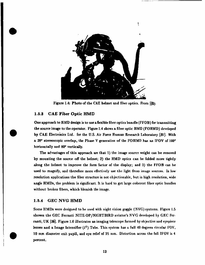
Figure 1.4: Photo of the CAE helmet and fiber optics. From [31J.
1.5.3 CAE Fiber Optic "MD
One approach to HMD design is to use a flexible fiber optics bundle (FFOB) for trallsmitting
the source image to the operator. Figure 1.4 shows a fiber optic "MD (FOIIMD) dcveloped
by CAE Electronics Ltd. for the U.S. Air Force lIuman Research Laboratory (31). With
a 38° stereoscopie overlap, the Phase V generation of the FOHMD has an U'OV of 1600
horizontally and 80° vertically.
The arlvantages of this approach are that 1) the image source weight can be removed
by mounting the source off the helmetj 2) the IIMD optics can he folded more tightly
along the helmet to improve the form factor of the displaYi and J) the FFOB can be
used to magnify, and therefore more effectively use the light (rom image sources. In low
resolution applications the fiber structure is not objectionable, but in high resolution, wide
angle HMDs, the problem is significant. Il is bard to get large coherent fiber optie bundles
without broken fibers, which blemish the image.
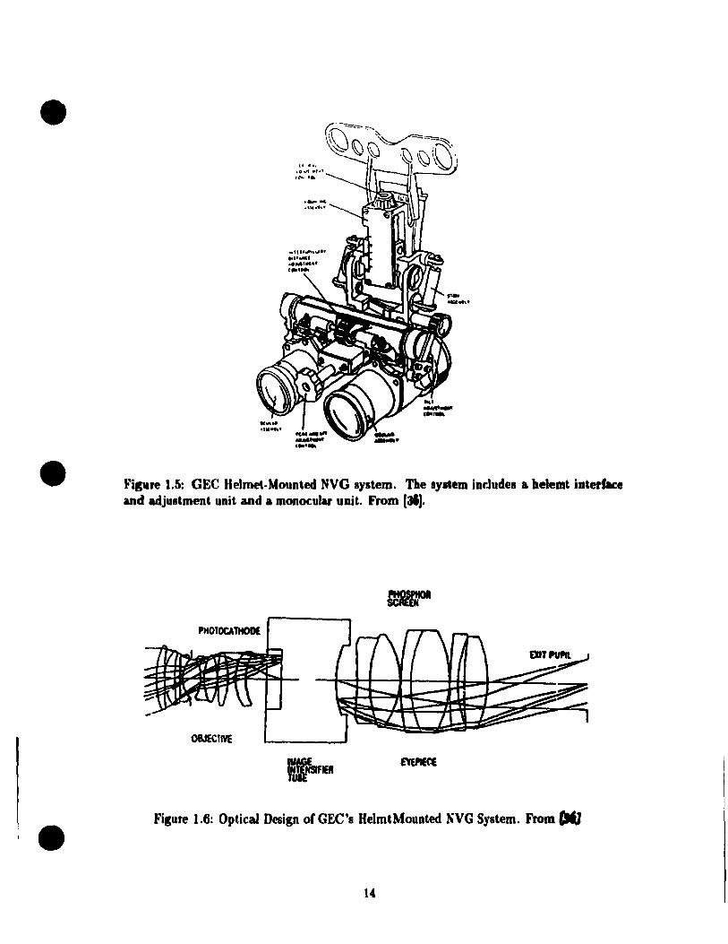
1.5.4 GEe NVG "MD
Some HMDs were designed to be used with night vision goggle (NVG) systems. Figure 1.5
showes the GEC Ferranti NITE-OP /NIGHTBIRD aviator's NVG developed by GEe Fer
ranti, UK [~). Figure 1.6 illustrates an imaging telescope formed by objective and eyepiece
lenses and a Image Intensifier (12 ) Tube. This system has a fuU 40 degrees drculac FOV,
10 mm diameter exit pupil, and eye relief of 25 mm. Distortion across the full IFOV is 4
percent.
13
•
•
•
'1 ." .0'" ., .. , te-. ' •
Fisure 1.5: GEe Helmet-Mounted NVG system. The system int.ludes a helemt interface and adjustment unit and a mononlar unit. From (31).
PH010CAlHODE
OBJECtIVE
Figure 1.6: Optical Design of GEe's HelmtMounted NVG System. From CIfJ
14
el
e
•
" " ,
. . . , ..-.. ,
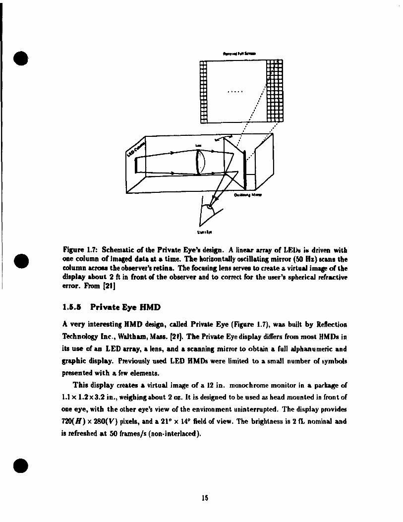
Fllure 1,7: Schematic of the Private Eye'l desiln. A linear array of LEU" i. driven with ODe column of imlled data At a Ume. The horizontally osciliatioK mirror (50 Hz) Kanl the column &Crosl the observer's retina. The focusinllenl serves ta create a virtu" im. of the display about 2 ft in front of the observer and to correct for the user'l Ipherical refractive error. From [21J
1.5.1 Private Eye HMD
A very interestins UMD desip, called Private Eye (Filure 1.7), wu built by Rcllection
Technology Ine., Waltham, Mus. [21), The Private Eye display differs from m08t IIMDI in
iu use of an LED array, a lenl, and a Icanninl mirror to obtain a full aJphanumeric and
Craphic display. Previously used LED UMDs were limited to a smalt number of symbols
presented with a lew elementl.
This display creates a virtual image of a 12 in. monochrome monitor in a parlcage of
1.1 x 1.2 x 3.2 in., weighinK about 2 oz. It is designed to be used as head mounted in front of
ODe eye, with the other eye's view of the environment uninterrupted. The display provideti
720(H) x 280(V) pixels, and a 21° x 14° field of view. Tbe brigbtness is 2 fi. nominal and
il refreshed at 50 frames/s (non-interlaced) .
15

•
•
•
1.5.6 Summary and General Description or BLHMD System
Ir. th"ir d,!vt'Iopmeflt, history ofmore than twod!!r.ades, HMDs were restricted to various mil
itary a,)plkations. JJccause of the requirements for image sources, optical designa of HMD
')llsh,!d th,! relat,{!d technologies forwardj in return, HMDs have bœn improved significantly
hy the d,lv,llo,)ment of new technologies. There are many alternate design approaches to
tJw mmporlflnt,s of IIMOs, yet none is superior. Which approach is chosen de pends u.,on
tJJ(' If M n's application and technologies available. Today there are many successful HMDs
d"sigJl('d and t,ested for various applications.
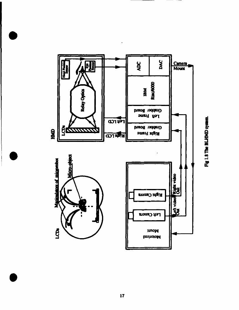
The nUIMO system, which will have stereo color vision and very wide instantaneous
FOV, is intended to be used in teleoperation. Figure 1.8 schematically shows the overail
UI,IIMD system.
Th(! rernoh! S('ene is viewed by two charge-coupled device (CCD) color cameras. Two
slightly differ,mt imagl's from these two cameras are digitized by two frame grabber boards
in iUl HlM IUSC/()()()O computer. The digitized real images are superimposed wit.h two
"oUl'Hlter genl'rated stereo images which presents useful information from various sensors.
Tht' two frame grabber boards send and display the superimposed stereo images on two
l'Olor LCI> screens which are rnounted with two optical relays on a helmet. Images on the
),( :ns arl' imaged hy the optical relays to form a pair of magnified virtual images at optical
infinit,y. Stereo color vision is achieved by the disparity of these two virtual images viewed
by both (·y,!s.
ln the mcantime the camera mount is driven by signaIs from the head tracking sensor
and ('ye position n)(!asllrement system such that the cameras point to the same direction as
tht' hl'ad and eyes.
The mM RISC/6000 computer manipulates the images by two frame grabber boards,
and also servl'S thl' Il('ad tracking sensor and eye position measurement system.
1.6 Human Factors and Design Criteria
n('fiLIlSl' IIMOs are int,cnded to be used as man-machine interface and the display, optical
r('lay and Ill'ad orielltatioll sensor are usually mounted on the operator's hearl, human visual
('haracf,cristirs and mounting constraillts dictate if a HMD is operational and safe. Moreover,
sinrl' il. is illll)Ossiblc to design and cOllstruct an ideal HMD, trade-olfs must be made to
('uhan<"e soml' visual pararnetcrs and compromise others. A good ullderstanding of human
fartors is thl' ollly way to make good trade-olfs .
Ther(' are four ('ategories of human factors to be considered:
16
• u Camera ~ Mouna
1 1 PIW08 J:aqqlJO ~:lVa,
a~u:r) 1 ~
pI80fI J:1QCIIJO
1 awu:l .... RI ! • ~
CIl! -l f
r1 -:> 1I!I!lI la
a~:>va,
• 17

•
•
•
J. radon; affecting df!tedion and recognition ability of human eyes, including luminance
levcl, wntral>t, retinal location of targets, viewing distance, field-of-view, binocular,
hiocular or monoC:lllar vision, and (,'llori
2. g(!C)mdry radors, such as interpupillary distance, pupil size, other geometric param
(!ll'rl> or the human head, and eye relief;
:J. safety and pnd uranœ factors, including the maximum weight a human head can sup
I.ort dllring a long period of practical operation, and shifts in the center of gravitYi
and
4. toleranfe of aberrations such as lateral color, distortion, field curvature, astigmatism,
,uul ('0111 a.
Consid(~ratinns of the first c!ass of factors indicate that an advanced HMD should have
ml or dlld hiflofular vision, an IFOV greater than 60°, adequate luminance (40-1000cd/m2),
ami high ('ontrast, and that a virlual image should he located at a reasonahle distance range
spt by ah('rration (:orreftions.
'l'hl' interpllpillary distance, whirh is around 63 mm, and the space needed to install
I('IIS('S S(·t tlH' limitation or the diameters of binocular lenses to no larger than 55 mm. The
('xit 1)!JI.il of the optkaJ relay, determined by the rotation of the eyehall and the pupil size
which is in tlH' range of 3 to 8 mm diameter, should have a diameter larger than 10 mm.
'l'II(' sllill)(' and sizl' of a human head dictate the arrangement of the combiner and elements
of th(' optkal f(·lay.
TIH' important optical aberrations in the optical design of HMDs include distortion,
lat,('ral rolor, fil'Id ('urvatllre, astigmatism, and coma. The tolerance of aberrations depends
upon allplkations and reqllirements. A wide IFOV optical relay usually has large aberra
tiollS, l'''n('(' low acuit.y. 'l'he compromise is to ensure small aberrations and high acuity in
t.11(' (·(·lIt.ral fidd of view, and large aberrations on the margin of a wide IFOV.
l'II(' IIM J) d('sign criteria, especially th(' optical design criteria, can be derived by consid
Nations of hmnall factors and opticaJ constraints. Details ofthis issue are given in Chapter
:1.
For cost and manufactllring reasons, only spherical lenses are used in the optical relay
of Uw BLlIMD syst(,lll.
1.7 Contributions of the Thesis
'l'hl' ront ributiolls of t his thcsis arc the following:
18

•
•
•
1. Derive optical design criteria by ronsid('ring human factors, whirh indud«' 1) factors
affecting visual acuity, 2) geom('try factors, 3) ab"rration tol('ranct's of Uu' hUlllan ('y«',
and 4) safety and endurance factors.
2. Design an optical relay for ust' in th(' nLHMD with tIlt' following charart«'l"Îst.irs:
1.8
• IFOV: larger than 60 dcgrccs,
• Distortion on full field: less than 2.5 perc(,lIt,
• Lateral color: less than 3.5 minutes,
• Field curvature: the tangential field curvature lies within O.R dioph'rs of t.h«'
central image plane, and the sagittal field curvature is I(,ss thau :1 diopt,l'rs wit.hin
a ±20o field-of-view, and no part of the field Îs beyond infillity,
• Coma: OSC less than 0.001,
• Diameter of exit pupil: equaJ to 10 mm,
• eye relief: equal to 20 mm,
• Totallength (of the straight optical relay): less thall 100 111111,
• Ali spherieal lenses, and
• Diameter of lenses: less than 5t1 mm.
Ol'ganization of the Thesis
This thesis mainly reports on the optical design for the fJLIIMD systl'rn.
Chapter 2 addresses optical design theories, including fi rst ordl'r optks, al,..rration t.hl',
ory, general principles to correct aberrations, and comput.er aidl'd h'fls d"fligll.
Chapter 3 shows the "MD system optical design ronst.raint" and t.argetfJ hy ('()lIsid('rillg
human factors and opticallimits.
Chapter 4 discusses design problems of a wide JFOV opt.ir rl'Iay. Bafli(' ffHlfliclNat.ions
and design procedures of the optie relay are present"d, a.,> w,,11 as tWH f(~slllt.illg df'siglls alld
corresponding analyses.
Chapter 5 contains the conclusions hased on the work J)erforrn(,ll .
19

•
•
•
Chapter 2
Lens Design Theory
2.1 Introduction
ln ord('r to providc a background in lens design, this chapter briefly reviews first orcIer
upt.Îfs, aberrat.ion thcory, sorne general design principles, and computer aided lens d«.>sign .
For d(!t.ail(·d discussions sec [18, 29, 32].
Ali lens design procedures are based on the principles of geometrical optics, which as
sum('s that. light t.ravl'Is a)ong rays that arc straight in a homogeneous medium. Light rays
an' f(·frart(·d or r(·fle('f.('d at a lens or mirror, whence they proceed to form an image. An
optkal imag(' systl'm iLlways has an object and an image. The space containing the entering
ra.ys at, il surfacl' ullder cOllsideration is known as the object space for that surface; the
SI'ilCt' rontaining the rays emerging from a surface is caUed the image spaCf for the surface.
n('ra,US(' of 0", ('xistl'ncc of virtual objects and virtual images, we must regard the object
and imag(' spa('('s "8 ovcrlappillg to infinity in both directions.
'l'hl' ba8il' and important chararteristics of an optical system can be obtained by first
ortl(!r 0l,t,il's. Du(' to the inlwrent properties of refracting and reflecting surfaces and the
displ'rsioll of rl'fracting Illl'dia, tll(' image of a point is sel dom perfect but is generally
élfllil'f.l'd wit.h al)('rrat.iolls. '1'0 dassify, identify, calculate, analyze, and correct aberrations
art· tasks of al)('rrat.ioll t.hcory. Bccallsc of the high non-Iinearity and complexity of most
optiral sysh'lIls, alH'rration corrections require delicate designs and huge caIculations. It
is illlpossibll' in ail rasl'S to obt.ain analytic relations between aberrations and structural
parameters of optical systems. Sorne cmpirical principles are very lIseful tools in the design
of optiral sysh'llIs.
20
•
•
•
2.2 First order Optics
2.2.1 Ideal Optical Systems
First-order (or Gaussian) optics is often referred to as the optics of idl'al opl in,1 sysl ('I\IS. An
ideal optical system is an abstract, structure-independcnt modl'I whifh fall 1)(' ('(Iuivah'nl 1.0
any particular optical system. An ideal optiral system should ha.w I,h('s(' f()lIowin~ prnpt'ft it's
[32]:
1. A point in the object space of this system corrcsponds 1.0 a unitllll' point. il' tlU' illla~t'
space of this system. This pair of points is caJlpd the cm' •• gatc points.
2. A line in the object space of this system corrcsponds t.o a, unitllt(' litl(, in t.h(' illla~('
space of this system. This pair of lines is caJled the fOujuga,t(' IÎlU's,
3. If a point is on a line in the object space of t.ltis syst('1II tlH' ('()njugate point lllllSt. 1)('
on the conjugate line in the ima.~e space of this syst('IIl,
8ased on the above definition, the theory of optical sysh'ms was d..riv(!c\ hy (;iLUSH in
1841, and later named Gaussian optics,
2.2.2 Cardinal Points of an Optical System
A perCect, or weIl corrected, optical system can be trea.tt'd as a "black box" whos(' dli1r
acteristics are defined by its cardinal points, which are ils first and s('('O(ul /ot·(lI,loud.~, il.s
first and second principal points, and its first and second nodal points,
Figure 2.1 illustrates the locations ofthe focal points and Jlrindpal point.s of a ~('I1('fali;f,('d
optical system. The object space is on the left of thc system, th(! image SPil('(' 011 Hu' right..
The focal points are tltose points at which light rays (from an infinitely dir-,t.ant. axial nhj('('t.
point) parallel to the cptical axis are brought to a commofl fO('1IS on thl' axis. Th .. 01.t.ka.1
axis is a line through the centers of curvat.urt' of t.he surfiu'(!S whirh rnak(' 11ft th .. opt,ka.1
system. If the rays entering the system and those emerging from lIlf' syst('1II art' ('xt.('Ilf!NI
until they intersect, the points of intersection will defin(' a surfa('c ('all('d tlu' ''''irU'11Hli IllmU',
In a weIl corrected optical system, the principal surfaces are sJ)I\('res, ('f'lItNf'd 011 tll(' ohjf'('t,
and image. In the paraxial region wher(' the distances from t.he axh. ilf(! infillit.f'simal, t.llf!
surfaces can be treated as if they were planes. Ttw inters(!('tion of this r-,lIrfa('(' with t.ll(' ilXiH
is the principal poir..t. The "second" focal point and tlU! "r-,ewnd" principal /loin', iH" t.llosf!
defined by rays approaching the system from the left (ohject !>pace). Tllf' "firr-,t" poinlf, aw
those defined by rays from the right (image space).
21

•
•
•
Optieal System
Liaht Rays From Lelt Principal ''Planes''
~I\IVI Principil Poi ..
Fim Focal PoiN Fim Point
Second Focal PobI
J OpdcalAxil --------- J ----------'""'.----t----,-_ItI_-----=--=--=--=-l-4
Filure 2.1: Dlustrated the location of the rocal points and principal points of a pneralizecl optic&! system.
The object space eJlective localleng'" 1 or the system is the distance from the flnt
principal point to the fint focal point (Figure 2.1). The im •• pate eJ1ectiœ locs/le"'" l'or the system is the distance from the second principal p,;,d to the second focal point .
H the refractive index of the object space medium difl'en from that of the imase space,
1 ~ l'. The baci locallengala ('11) is the distance from the vertex of the lut surface of
the system to the second focal point. The frona loœl/engda (f Il) is the distance lrom the
vertex of the front surface to the flnt focal point.
Filure 2.2 shows the deflnition of nodal points. The nodal poin', are two axial pointa
such that a ray directed toward the flrst nodal point appean (after passins throuSh the
system) to emerp from the second nodal point parallel to its orisinal direction. When aD
optical system is bounded on both sides by air the nodal points coïncide with the principal .
points.
2.2.3 A Simple Lens System
Figure 2.3 shows a simple lens system, which has radii ri and r2, a center thicknes8 tc,
and a refractive index n". It i8 immersed in an object space medium with homogeneous
refractive index n, while the image space medium has a homogeneous refractive index n'.
The effective rocallengths 1 and l' can be round by equation 2.1:
, 1 = !! and l' - !!.. k - i (2.1)
22
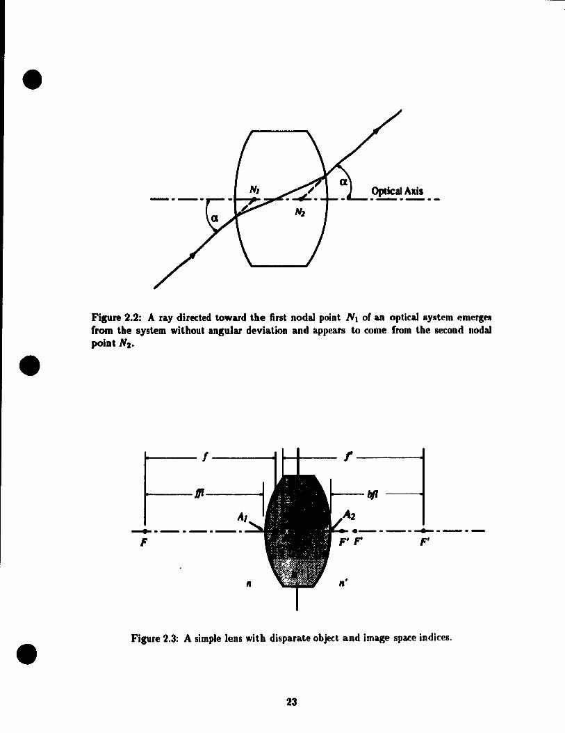
•
•
•
Fisure 2.2: A ray directed toward the first nodal point NI of an optical system emerges trom the system without angular deviation and appears to come from the second nodal point N2 •
1----- 1----..... 10--1---- ,-----01
10--- bfl ---.1
-..------- e- - -- _____ - _.-
F F'
Il Il'
Figure 2.3: A simple lens with disparate object and image space indices .
23
•
•
•
where nIf - n n' - nIf te(n" - n)(n' - n")
k= +--Tl T2 n"TI T2
(2.2)
The locations of principal points If and H' with respect to the two vertices of the lens Al
and A2 are given by equations 2.3 and 2.4:
n'te n" - n A2H' = - T( n"rl )
Plea.o;e note the following sign conventions.
(2.3)
(2.4)
• TI or T2 of a surface is positive for the center of curvature to the right of the surface,
and negative for the center of curvature to the left of the surface.
• Alli is positiv(' for the first principal point H to the fight of vertex Al (interior to
the lens), and negative to the left of vertex Al (exterior to the lens).
• A2 /1' is I)ositive for the secondary principal point H' to right of vertex A2 (exterior
to the lens), and negative to the left of vertex A2 (interior to the lens).
Nodal Iloint locat.ions are:
AIN AIH +HN
A2N' = A2H' + H' N'
when'
H N = H'N' = (n' - n)/k,
whirh is posit.ive for N t.o the right. of H and N' to the right of H'.
2.2.4 Combinat ion of Ideal Optical Systems
(2.5)
(2.6)
(2.7)
Ma.ny mmpl('x illmging tasks cannot be performed with a single Jens. Any number of Jenses
can be dealt wit.h by considerillg the coaxial combination of two lenses and then combining
t.his "f'ombination" with the next Jens, and so on, until aU the lenses in the system are
a.frounted for .
Figure 2.4 shows the coaxial combination of two idE'al opUcaJ systems. Given the focal
Il'ngt.hs. Il,1;, h. f~, the locations of cardinal points, Hl, H~, H2' H~, Ft, Ft, F2' F~,
24

•
•
•
1 1
F HI FI
1 1
Fzt 1 Ht Ft --+---1-----
1 --+--...-.- • HZ: ...... --r-·-.-
1 '--1 1.
.. X r- !'--
XH~
Figure 2.4: Coaxial combination of two ideal opticaJ systems.
oC these two systems, and the separation of the two system represented by d (the distance
between H' and H2) or A (the distance between F{ and Fz), we can find the cardinal points
and focallengths of the combined system: H, H', F, F', /, l'. The focallengths, / and
/' t are given by equations 2.8 and 2.9:
/= !th -T (2.8)
1'= /U~ -"6 (2.9)
The locations ofthe principal points which are measured by XH, the distance from H to
Fl, and XH't the distance between H' and 1;, may be found by equations 2.10 and 2.11:
(2.10)
X - J,A+/;+12 - fI!! H' - 2 A - 'lA (2.11)
Note the sign conventions. Assume that incident rays of light come from the right.
1. â is positive if Ft is to the left of F'l, negative otherwise.
2. dis positive if Hl is to the left of 82, negative otherwise .
3. XH is positive if H is to the left of FI, nesative otherwise.
25

•
•
r la
-L
Figure 2.5: Image position and size of an ideal optical system.
4. XH' is positive if H' is to the fight of r" negative otherwise.
2.2.5 Image Position and Size
When the cardinal points of an optical system élIe known, the location and size of the
image formed by the optical system can be readily determined (see Figure 2.5). The image
position z' (the distance from the second focal point to the image plane) or" (the distance
from the second principal point to the image plane) can be obtained by the Newtonian
image equation 2.12 or the Gaussian image equation 2.13 separately. The Newtonian image
equation is:
II' = -zz'
The Gaussian image equation is:
1 1 1 - = -t-3' 1 3
Note the sign conventions .
z' = _II' z
l= sI (s + f)
(2.12)
(2.13)
• Distances measured from the left of a reference point are negative, to the right, posi
tive .
• The focallength of a. converging lens is positive and the focallength of a diverging
leRs is Regative.
There are two parameters to describe the size of an image of an optical system (Fig-
• ure 2.5), the latl'ml (or transverse) magnification m, which is given by the ratio of image
size to object size, a.nd longitudinal magnification M, which is the magnification of the
26

•
•
•
longitudinal thickness of the object. m and nT can be fOUlul by ('quations 2.1·1 and 2.15.
h' s' f s' (:U·I) m = -= -= ---
h S f' S , , , , ni' = 82 - SI ~. 82
~ 1n2 (for slIlall thkklwss) (~.I!i)
82 - St St 82
This indicates that longitudinal magni ftcation is ordinarily posit iv('. Nol l' 1 hal h('i~h t.s "hoV\'
(helo",) the opticaJ axis are positive (negat.iv(').
2.2.6 Limitations of First Order Optics
The first-order optics theory is only complet('ly affllratl' for ail illfi"itpsllllal tl"'padli"(' l't'
gion about the optical axis, knowII as the IJflm:rzal'·('f/Wll. Th(' valut' of li l'st -onl"1 pxpr('!'.!'.iolls
lies in the fact that a well-corrcct('d opt.k,11 systPIII will follow t tH' fjl·st.-oJ'(lPJ' PXPIPhhiollh
almost exactly and also that th(' first-ordN imag(' posit.iolt alld siz('s l'ruvid(· .1 ('oltV('IIit'lI
t reference from which to measurp departllr('s frolll Iwrfp('tioll. In .Hlditloll, tll(' l'al'axlal
expressions are much casier to Il!>C tha.n trigollompt.rifal ('(Illatiolis.
When the behavior of lenscs with finilp apNtllr(' a.lld lipld of vif'w tS ('011 i"oidf'l'pd, t.hf'
amount of aberrations of the lenses must he d('tNlllilJ('d alld 11<'11('(' t.11f' ahNratiOlI t."('oryof
lenses is needed.
2.3 Aberration Theory
Aberrations of optical systems are measured hy t11(, amollnt hy whidl 1ft y!'. mÎhs t!u' pa,r,Ixial
image point. This work of determi n ing th(' ah('fration~ ('ait ilOt. 1)(' dOIlI' f'a!'.il y 1111 t.il 1 hl'
various types of image faults are c1assifted alld the I)('havior of ('itd. I.YP" i!'. wf,1I "".!"I !'.l.o(J(1.
To evaluate each aberratioll. ollly a fcw rayf> 1I('pd 1)(' I.ra( ('(1. Th Il!'. 1 lu' prohlPIII ":.~t,,,J(·!'.
more manageable proportion~.
There are two class('!! of a.berration!>: mOIl odlJ'fJ/lI a 1 il' a lu'rrat.iollh .lIId ( III 0111,. t.ir ,.t,,'r-
rations. If th(' imagc of ail optieal ~yf>lem is fOrJJI('d oJlly hy I/IOlJoI·hrom,.li( Ilghl., tlif'
optical system has fiVl' kinds of ah('Jratiolls: ~ph('fÎl:al alH'rrat.ion, (0111<1, ,I!'.IIJ!,lJlal.ihrrl, Ppl
zval curvature,and distortion. Ofthche ahl'rr<ltionr-., r-.ph('rir,ll alu'lrallf)JJ b ollly ,. ''''UtiOIl
of aperture (becoming significalil. only wlll'JI tI,P <lrU'rl.llr" in( rroil,<,l'!». ProlZVilJ (!llvallll'l' alld
astigmatism are only f"lIftions of field of vipw. The Ot.hN!'. aJ'l' fllurtlOJl:' of hol.h ilpr·rl.t1r'·
and field of view .
But most optical system!> form images in white Hght or IIIl1lti-t hromal.Î( ligllt. Sinf'" tlil'
27
•
•
•
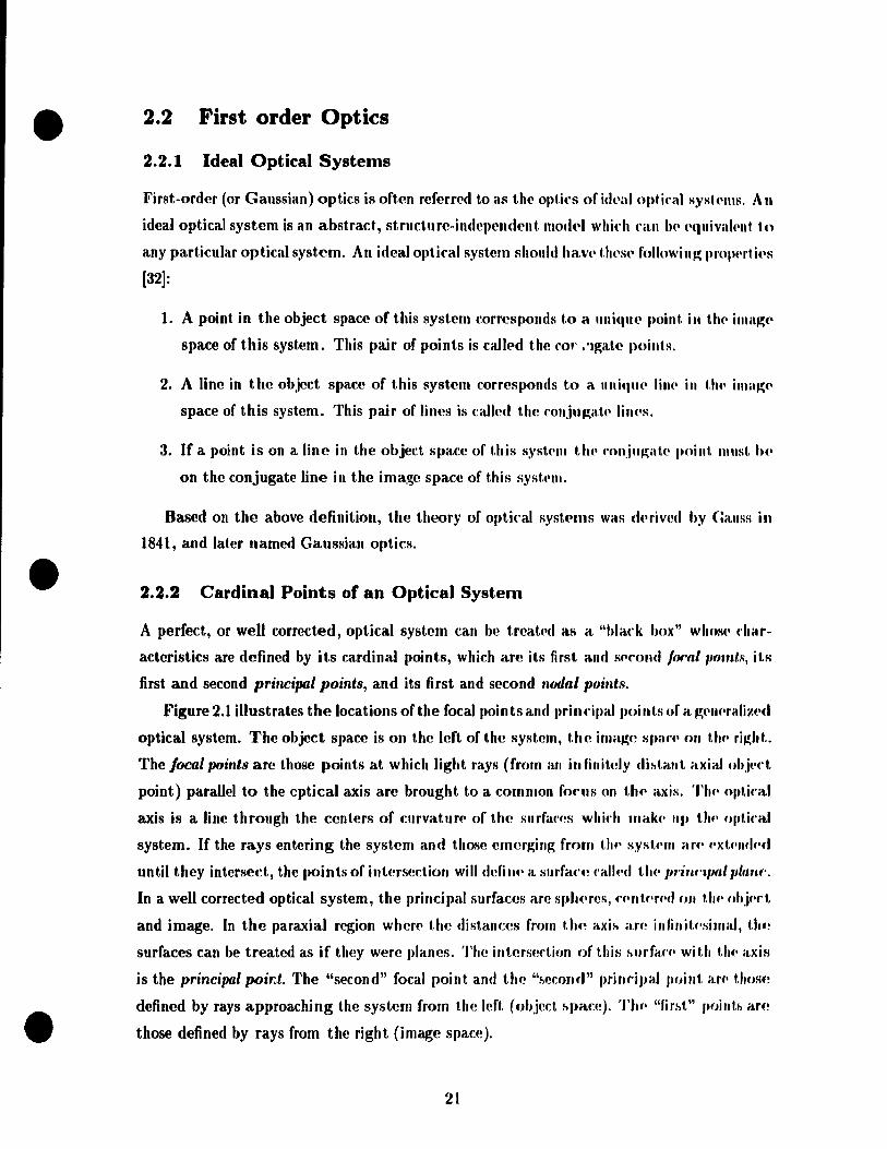
•
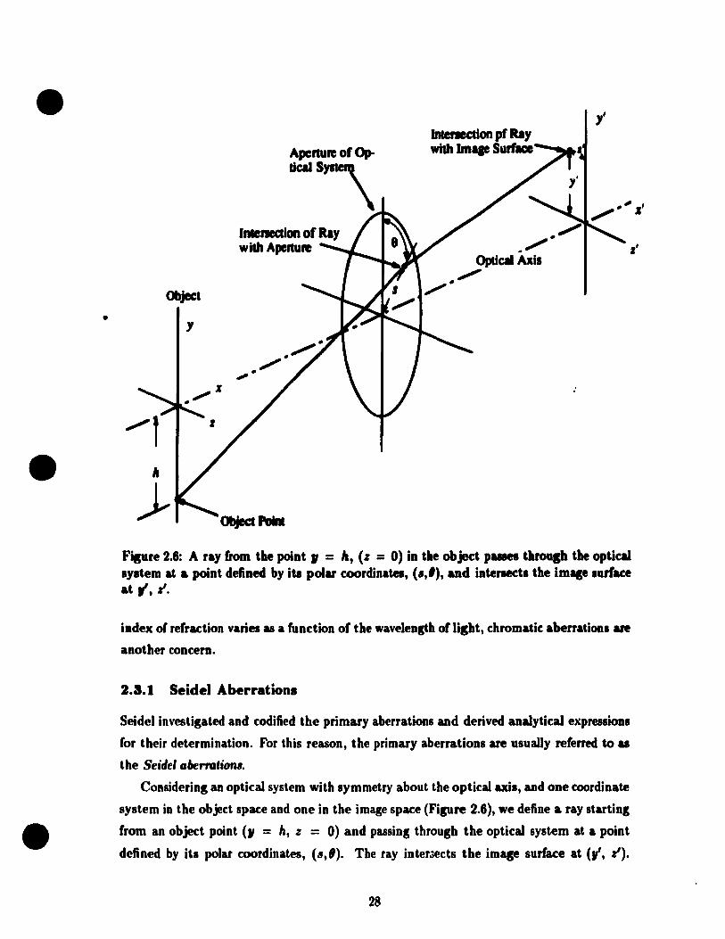
Il
Object
Y
)..
Aperture of Op-
-\ Intenec:tion of Ray widl Aperture
Interecdon pf Ray widl Ima. Surface --_ ....
l'
Filure 2.6: A ray!rom the point, = la, (z = 0) in the object paues tbrou" the optical syltem at & point defined by its polar coordinatea, (l, '), and intenects the im. surface
at ", z'.
index of refraction varies as a function of the wavelensth of lilht, chromatic aberrations are
another concern.
2.3.1 Seidel Aberrations
Seidel investigated and codified the primary aberrations and derived analytical expressions
for their determination. For this reason, the primary aberrations are usuaUy referred tG as
the Seidel abernllioRl,
Considering an opticaJ system with symmetry about the opticaJ axis, and one coordinate
system in the object space and one in the image space (Fipre 2.6), we define a ray starting
from an object point (, = h, z = 0) and passing through the optical system at a point
defined by its polar coordinates, (",1). The ray inter3ects the imqe surface at (V, z').
28
•
•
•
Considering the axial symmetry of the system, the general form of the exprt'ssions of y' and
z' can be derived as follows [29]:
y' = Atscosll + A2h
+BtS3cos9 + B 2s2h(2 + cos28) + (383 + B4).~h2costl + IIft"a
+Ct s5 cos 8 + (C2 + CJ )s4h + (C4 + CG ('os2 9).~:W}. ('Os 8
+(C7 + Cscos29)s2hJ + ClOsh"cos9 + Ct2h5
+Dts7cos9 + z' = Ats sin Il
+Bts3sin9 + B2s 2hsin211 + (83 + 8 .. )sll2 sin8
+Ct s5 sin 9 + C3 s4h sin 229 + (Cs + CG sin2 Il) .• iJh2 sin Il
+C9s2h3sin28 + Cu sh" sin8
+Dts7 sin 9 + ...
(2.lfi)
(2.17)
where Ai, Bi, etc., are constants and h, s, and 8 have becn d("ia ... d ",bov(' and in Fig .. r.' 2.H.
In the above equations, the Ai terms are first-order t('rms relating t,o t,lu' paraxiaJ im
agery discussed in Section 2.2. Ali the other t.crrns are called trallsv('rs(! ah..rrat.iolls. Tllf'y
represent the distance by which the ray misses the ideal image I,oint as d.'snil,.'d hy tlH'
paraxial imaging equations. The BI terms are ralled the third-ordf'r, S('id.'I, or l'fillla,ry
aberrations. Bt is the spherical aberration, 8 2 is the coma, Ba is Hu' a." t, iglllal,isIII, /l,.
is the Petzval curvature, and B5 is the distortion. Sirnilarly, thf' (,'. tf'rlIIs ilr(' mlh'ct t,lH'
fifth-order or secondary aberrations. C. is the fifth-order sJ,'U'riral ahNrat.ion; C'I. illtd (::1
are the linear comaj C .. , Cs and C6 are the oblÎflue !.pherical abNration; (:7, CM ,lIId n, iLf('
the elliptical coma; CIO and Cu are the Petzval curvatur(! and a.st.igrnat.isrn; and (:1'1. is Hw
distortion. The 14 D, terms are the seventh-order or tertiary atwrrat,inlls.
In an axially symmetrical system there are 110 evelt-ordf'r al)('rmtiollsj unly mld-ordN
terms may exist.
This section will present the definitions and reIHeS('fltat.iolls of t.h(! Sf'id('1 alH'rfilt,iolls
(the B, terms), and will discuss each aberration's c:haracteristics alld fad,orl> afff,('t.iltg il..
Spherieal Aberration (the BI Term)
SphericaJ aberration can be defined as the variation of forus with alH!rtu ff~. Figu ff' 2.7 if!
a sketch of a simple lens forming an image of an axial ohject point a great dif>tafu'f! away .
The spherical aberration can be measured in the vertical direction (called tJI(~ tranSVNS(!
29

•
•
•
• Paraxi" FocUi
Fisure 2.7: A simple conver&ins lens WiL" undercorrected spheric" aberration. TAi. the transverse spheric:a1 aberration; LA il the longitudinallpherieal aberration. The ra.y. larther Irom the axil are brousht to a locul neuer the lens.
spherical aberration), or in the axial direction (c:alled the Ionsitudinalspherical aberration).
For a given aperture and local lensth, the amount of .pherical aberration in a. simple
lens is a function of object position uad the .hape, or bendins, of the len •.
The imase of a. point lormed by a lens with spherical a.berration is uluaUy a bript dot
surrounded by a. halo 01 Bsht. The eft'ect 01 spheric:al aberra.tion OD an extended im ... i.
to solten the contrAIt 01 the image a.nd to blur itl detail •.
Coma (the B2 Term)
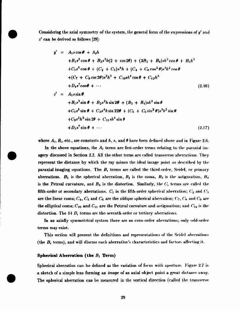
Coma is an off·axis aberration as shown in Fipre 2.8. At non·zero field anpes, coma appean
as a dift'erence in magnificcl.tion for difFerent parts of the lenl lurlac:e. The appearance of
a point image formed by a comatic lenl is a comet.shaped ftare as indicated in Figure 2.9.
This causes blurrins in the image plane of ofF·axis object points. Coma may be expressed
by OSC . Offence Blainst the Sine Condition.
Coma varies with the shape of the lens elements and also with the position of any
aperture or diaphragms which limit the bundle of ra ys formins the imap. In an wally
symmetrical system there is no coma on the optical axis. The size of the c:oma patch varies
directly with itl distance from the axis.
ln a particular desip it may be controUed either by blendins of the elements or by
appropriate matchins with associated objectives and transler tenses.
30
•
•
•
Focal Plane
Apenuœ.
Fipre 2.8: Coma appean &1 a difrerenee in magnifieation for difl'erent parts of the lens IUrface. Coma ean he described by ose (Oft'ense &Kainlt tbe Sine Condition) .
Fisure 2.9: Tbe coma patch. The image of a point source is spread out into a comet-shaped ftare .
31

•
•
•
--------
principal rav
............. "ttal pline
" \ op,ie" sYI'em
object pOint - •
l sagiual imago '-=--- ffocal linel
----
Fisure 2.10: Astigmatism cao be presented by these section al views. From [13].
A1tismatilm and Filed Curvature (the B3 and 8. Ter .... )
-------
A schematic view of an optical system imagins an ofF·axis point il shown in Figure 2.10 [13J.
A pair of focallines, tansential and sagittal, can be found. In between these lines, the imase
is either an eUiptical or circular blur. The separation of these two line is astismatilm.
Fisure 2.11 shows the definitions of field curvature and astismatiam.
Field curvature refers to the efFed that opticalsystems imase better on curved IUrfaces
rather than on ftat planes. In the presence of astigmatism, there are two separate utipnatic
focal surfaces corresponding to the tangential and saBittal fields, and the tanpntial imap
surface lies three times as far from the PetzvaJ surface as the sasittal lurface. In the
absence of astigmatism, tangential and sagittal focal planes fall into the same curved surface
called the Petzvalllurface. Usually field cUM/alure means the lonsitudinal departure of the
tangential or sagittal im~e surfaces from the ideal ftat image surface. We express the field
curvature in diopters, which is the reciprocal of the lonsitudinal distance in meters from
the tangential or sagittal image point to the location of the human eye . the exit pupil of
the optical relay.
The amount of astismatism in a lens is a function of the shape of the lens and its
distance from the aperture which limits the size of the bundle of rays passing through the
lens. The Petzval curvature is a function of the index of refraction of the lens elements and
their surface curvature (this will be discussed later this chapter).
Owing to the high concentration of positive power of eyepieces, oo1y moderate control
exists over the Petzval sum, so that in the absence of astigmatism the field is highly curved
32

•
•
•
Petzval SUrf:~ Saliual Focal Surfl Tanaendal Focal Surface ~ '----" , ,
~~
--~-------------_. ",/.,
L~ /
~. X,
Field CUrvatum = X, and X,
i 1 .1
Figure 2.11: Field curvature is the tendency to image better on curved surfaces than the ftat planes. The astigmatism is the separation between the tangential surface and the sagittal surface.
convex toward the eye. It may be neutralized by introduction of over corrected astigmatism,
but too much oHhis will badly blur the outer image. The compromise is up ta the dcsiKner,
who must consider the end use of the instrument. If the tangential and sagittal field curves
alIlie within 1 diopter of the central focus, the image wiU he reasonably weil defincd over
the field.
A flat tangential field combined with a 3 diopters curved sagittal field will just about
correspond to the largest astΫmatism that can be toleratedj in this case the outer field i.
uselulonly for identifying the presence of a possible target.
ln the case of wide-ans)e eyepieces, the presence of higher-order astigmatism should he
watched for, since violent changes of the tangential field can occur and mal.e the design
unusable.
Distortion (the Bs Term)
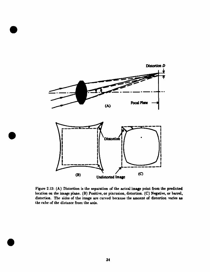
Distortion is the separation of the actual image point from the paraxiaJly predicted location
on the image plane, and can be expressed either as an absolu te value or a perccntage of the
paraxial image height (Figure 2.12). Distortion means that even if a perfect off-axis point is
formed, its location on the image plane is not right. lIence distortion does not lower "Y stem
resolu tion.
The amount of distortion ordinarily increases as the image size increases. There are
t..-o kinds of distortions: overcorrected, or pincushion, distortion and negative, or barrel,
distortion.
Distortion is a function of aperture position and magnification. When a thin lens coin-
33
•
•
•
(8)
(A)
Distortion D
Focal Plme
----, ~--"'--- 1
1 • 1
1 1 1
1 1 1 1 1 1 1 1
/----------~
Undistorted lm. (C)
Figure 2.12: (A) Distortion is the separation of the actuaJ imap point from the predicted location on the image plane. (B) Positive, or pincusion, distortion. (C) Nesative, or barrel, distortion. The si des of the image are curved because the amouot of distortion varies as the cu be of the distance from the axis .
34

•
•
•
Rly
____ ~f===fT&.t BlueU ...... y
-------------
Focll Plille
Figure 2.13: Lateral color, or chromatic ditrerence of magnification, of a simple lens. The lateral color, which is defined as the difl'erence b in the imap heipt, or the angle 0 between red and blue rays of light. results in difl'erent·sized imagea for difl'erent wavelengths.
cides with an aperture, there is no distortion. AI80, perfeetly symmetrir.al optical system.
at 1:1 mapification have no distortion. It shouJd be apparent that a Jens or lens system
has opposite types of distortion depending on whether it is used forwarda or backwards .
2.3.2 Chromatic Aberration.
Chromatic aberrations are cauaed by the fact that the index of refradion varies 88 a function
of the wavelength of light. In general, the index of refraction of optics materiaIs is higher for
short waveJengths than for long wavelengths; this causes the short wavelengths to he more
strongIy refruted at euh surface of a lens, therefore they have difl'erent magnifieations.
When a lens system forms images of difl'erent sizes for difl'erent wavelengths, or spreada
the image of an off·axis point into a rainbow, the ditrerence between the image heights for
ditrerent colora is called lateral color, or chromatic difl'erence of magnification. Figure 2.13
shows the definition of lateral color.
Another chromatic aberration is the longitudinal chromatic aberration, which is the
distance aloog axis between two focus points formed by blue light rays and rcd light rays.
The image of an axial point in the presence of ehromatic aberration is a central bright
color dot surrounded by a color halo; the dot color and halo color are dependent on the type
of chromatic aberration (undercorrected or overcorrected) and tbe position of the screen on
wbich the image is formed.
Chromatic aberrations vary with the optieal materials, the shape of the lens elements,
and also "'ith the position of the aperture of the system. As in the case of spherical
aberration, positive and nesative elements have opposite signs of chromatic aberration.
35

•
•
•
Aberration IJateral Spherical Longitudinal Spherical Coma Astigmatism Field Curvature Distortion Chromatic
Aperture Image Height
Table 2.1: Variation of aberrations with aperture and image height.
Jlt'nce, chromatic aberrations can be compensated by grouping of positive elements of low
dispersion and negative clements of high dispersion, or by using high dispersive prisms. For
a sirnpl(! lens lateral color is zero when the stot> is in contact with the lens.
The chromat.k variation of index also produces a variation of the monochromatic aber
mt.ions discussed in Section 2.3.1. In general the effects are of practical importance when
1 h(' basic aberrations are weil corrected.
2.3.3 Summary
lJy dassifyillg the various types of imagp. faults and by understanding the behavior of each
type, the work of determinillg the aberrations of a lens system can be simplified greatly.
Tllere are live c1asSf'S of monochromatic aberrations and two kinds of chromatic aberrations.
The above discussions of each aberration showed the strong dependency of aberrations
on ap('rture and field size or angle. Table 2.1 summaries the relationships between the
I,rilllary abt'rrations and the semi-aperture height y and image height h. Aberrations are
also funrtions of shapes of lenses, optical media, location of the aperture, and structure of
1('lIs systems.
Equations 2.16 and 2.17 shows that the fifth or higher order aberrations are much more
C'Omplicated tllan the third order aberrations. For many optical systems, the tbird order
t,t'rm is ail t.hat may be needed to quantify the aberrations. In highly corrected systems or
t.hORe havillg larg(' apertures or a large angular field-of-view, third order tbeory is inadequate.
III thes(' r"R('R, (,Xat't trigonometric ray tracing is essential.
2.4 Correction of Aberrations
'1'0 correct aberrations of an optical system to a level required bya particular application is
where all110st ail design effort lies. The correction of aberrations is a highly non-tinear, multi-
36
•
•
•
variable optimization process through the adjustment of availablt' structura.l paramt't,Ns.
The design freedoms of an optical system usuaJly include the radii of HU' surfaœ, t.11l'
thicknesses and air spaces, the position of the aperttlrt', and the refra(·tiv(' indl'x and dis
persive powers of the glass from which the lenses are made. The best, W(' ('all dn 1.0 cont'('t.
aberrations is to use our knowleuge of aberrations and available design fr<'edoms tn imprnv<,
the resulting image.
2.4.1 "Blending Technology"
The lens focallength equation 2.1 reveals t hat for a given index and thifkn('ss, t.IJ('f(' is lUI
infinite number of combinations of rI and r2 which will produce a giv(m foca.! Il,"~th. 'l'lU'
aberrations of the lens are changed markedly as the shape or "hlt'nding" is dlall~('(1. This
effect is the basic tool of optical design.
For a single lens, applied under certain conditions, it is Ilot difficult t.o filltl t.lU' t:lHV('S
of aberrations as functions of lens shape [29, 18]. For eXaml,I(', il. w .. s showll ill I~HI that.
with a stop at a lens and at 1/10 covering a ±17° field, tht' IClls has a z('ro va.lut' of WIIIII.
and minimum spherical aberration when the lens shape is lI('ar COllvl'x-plallo fortll. III ft
complex optical system, there are no such simple and general rdations l)t'tw""11 If'IIS shalU'S
and aberrations of the system. In this case, experience plays ail Îml)ort.allt roi.,.
For reasons of manufacture and cost, most lenst's have spherical shap.'s. nut. asplll'rimi
shape lenses have more advantages in controlling aberrations than spht'rkal 1('lIs('s. A
Schmidt aspheric correct or plate, for example, is an aspherical I.'ns US(!" with (!y('I,Îen's t.u
flatten the field-of-view.
2.4.2 Petzval Sum and its Correction
Consider a surface radius of r in a Jens system which has k surfaces. If Hw iru!c'xes of
reflection of mediums before and arter the surfacc are n alld n' separat,(lly, tlU! radii nf
curvature of the object and the image of this surface are reprcficnted hy fI and p', and lI,1I
aberrations are somehow eliminated except for the field curvaturp, t.hen for t.his slIrftu'(', wc'
have [18] lIn' - n
n'p' np nn'r (2.Jli)
Write this expression for every surface in the lens (k surfaces) alld add 11", W(' fjnd t.hal.
1 k n' - n nlpJ = E nn'r
1=1
37
(2. W)

•
•
•
It shollid he noted that a positive value of P corresponds to a negative sag, or an in ward
curving surface. Hence the sag of the curved image of a plane object with Pl = 00, in the
absence of astigmatism, is given by:
(2.20)
This is the famous PetzvaJ theorem, and the Petzval sum is defined as
1 Il ni - n Petzval sum == - = nk E 1
P 1=1 nn r (2.21)
The Petzval sum provides an excellent indication of the likely amount of field curvature
thlLt will be found in the central part of the field of a lens after the astigmatism has been
remov(·d, or, alternatively, an indication of the residual astigmatism that may be expected
aft«~r the rneridiollal field locus has been f1aUened.
'1'0 secure a fiat field frœ from astigmatism it is necessary to reduce the Petzval sum;
this ('an be don(' either hy widely separating the positive and negative components of the
1«'lls, by th(' lise of a very thick meniscus form, or by the use of a high-index crown glass
('olllhin('d wit.h a low-index fljnt glass.
2.4.3 Location of Aperture
l':very optical system has apertures or stops. The function of apertures is to Hmit the bundle
of rays forming images. It il' obvious that, depending on iL:. position in a lens system, an
aperturc s('leets sorne rays from an oblique pencil and rejects others. If the stop is moved
along the axis, somc of the former useful rays will be excluded while other previously rejected
rays ar(' now included in the image-forrning beam. Consequently, unless the lens happens
to h(· I)crf(·('t, a longitudinal stop shift changes ail the oblique aberrations in a lens. But
silllilar t.O Ut(' case of lens shape, the rela.tions between position of aperture and aberrations
of ft Il'ns syst('IU depend strongly on the structure of the lens system. The equations of
t.hird-ordt'r al)('rrations of .. hin lenses as the functioe of aperture shift can be obtained if
t.lU' thickrwss of clements in thl' system can be negligible [29J.
If tlU' apNt urt' is located in the middle of a completely symmetrical optical system, i.e.,
tlU' (·I(,lUents hehind the aperture are mirror images of those ahead of the aperture and the
system opemt('s at, IInit rnagnifkation, the coma, distortion, and lateral color of the system
ar(' id('utiraJly zero. This is the symmetrical principle, a principle of great utility, not
38
•
•
•
only for systems working at unit power, but eVl'n for syst,l'II1S working at inlinih' ('()n.iu~élt.t·S.
This is due to the fact that, although coma, distortion, and latNitl rolor art' not (·olllplt·h·ly
eliminated under these conditions, they tend to be drast.icaJly r(·dllf('(1 wllt'n t II(' d('lIIt'nts
of any system are made symmetrical, or even approximatl'ly so. For 1 his n'ason Illêlny
tenses which coyer appreciable field with low distortion and low coma h'nd ln 1,.. ~('ll(IraJly
symmetrical in construction.
2.4.4 Optical Materials
The most common lens material is optical glass, but crystals and 1)lastif art' fr(·(llH'nt.ly Us(·d.
The optical glasses are classified roughly as crowns and flints. Crowns ha.w a V-vahl('
of 55 or more if the index is below 1.60, and 50 or mon' for ail ind(·x ahoVt' !.fiO. Th(· flint.
glasses are characterized by V-value less than tlwsc limit.s. A high refrad.ivI· ind.·x It'ads to
weaker surfaces and thereforc smaller aberration rcsidnals, but high-ind('x glasst·s ar(' IIslIally
expensive, more dispersive, and dense. Various glass tyP('s an' oft('n (·olllhill('t! 1.0 fOnt.rnl
chromatic aberrations. An achromatic doublet, for exampl(', fOnsisls of ft low-rl'hltiv('
dispersion element of the same sign power as the doublet alld a high-l'I·httivf·-disPNSioll
element of the opposite sign. Several factors other th an aberra.tions, sud. ali (·ost., wI'ight,
and application conditions, have to be weighed whil.~ choosing ~Iass t.ypf's.
Plastic optical materials are rarely used for J)recision o.,tkal ('l''Jlu'n''s, 1)(,f"il.IIS(' of thl·i r
softness, high thermal expansion (eight times that of glass), high t.(·IJII)(·rat.lIrt· ("of·flidl'llt. of
refractive index (120 times that of glass), and other disadvantages.
Gradient index media, whose refractive index vari('s froJJl point to pnint. within t.l1{'
media, are attractive because they may result in cost saving in SOIllI' (·iISI·S, J)f'r1Ii1PIi, for
example, where aspheric surfaces can be replac('d by gradient (·Ienlf'nts. But il, is not f'ilRY
to make gradient index lenses to have a desired index profile.
2.5 Computer Aided Lens Design Optimization
There are many approaches to the computer aid"d lens design (CA Ln); allIIost ail of thf'lll
are characterized by the use of a "merit function". 'l'tu! merit fUJldion is il singh! nllfll('rkal
value which indicates to the computcr whether any givclI chang(· has illlprovl·d Hu' ImlH or
not. Usually the merit function is a collection of aberrations and departurf'" from d(·"irf'fl
conditions. The departures from desired conditions are ("olJlIf.l!d ar-, alu'rratiolll> in HHI ('()fI
struction ofthe merit function in the following section. 'l'tif! most pOIHJlar lIIf'thod i/l CALf)
is the Levenberg-Marquardt algorithm. The rncrit. fUfiction of this algorithlll if! f!flUal 1,0 Ut(!
weighted sum of the square of ail aberrations cOIH:erned plu" ttlf' sum of wl'ighl,(·d MI"ar"s
39
•
•
•
of ail th(! paramcter changes (damping b1rm). The adding of the damping term penalizes
any larg(' pararm!tN dJangeB and h!nds to stabilize the process.
Assurrw an optical ~y~tcm has k configuration parameters, x = (XI, ,X2, ..• , Xk)T. Its
starting point if, xo = (XI, ,X2, ... , Xk)'J'. For a given location of an objective and a given
a')(Irtur(' or a FOV, th(' ahflfrationl> (including the departures from desired conditions) of
UU' systmn are totally determifl(!d, and may be written as functions of the k variables as
follows (assume a total m kinds of aberrations, 1:, ,/2, ... ,1:"', are concerned):
i = 1,2, ... ,m (2.22)
The rn(!rit fUfl(:tion is
m k
1ft = LP~/? + ,\ L(Âx)2 a=1 J=l
m k
= L 1,2 + ,\~:::< Âx j )2 (2.23) a=1 3=1
wh(lf(l Ita, i = t, 2, ... ,m, are weight factors, ,\ is the damping factor, and li = pd: is t,he it.ll weighted aberration. Aberrations are non-linear functions of the configuration
variables, and CéLn he linearizcd hy expanding them in Taylor series at the starting point
xo , élnd only taking the tinear terms:
r = ro + AÂx (2.24)
w))('rp rand ro art' the aberrations in matrix form after and before the configuration param
('''NB rha,ng(l, Âx is t.he changes of the configuration parameters, and A is a m X k matrix.
They art' t'Xflf(lSSl'd as:
Il Ir ÂXt
r = h f'o
~ Âx
ÂX2 =
1111 I~ ÂXk
~ Qh.. ~ 8X2
A = ~ ~ U!
M; U7 !l1m 8Xk
40

•
•
•
The element 81. in the rnatrix A can he approximat.ed as fnllows: ~
(2.2!l)
Th .. conditions that If' is a minimum arc:
n,
or the following simultalieous equat.ions:
l~ 2 XI fl~ + h~ + ~ + lm 3'1 + À~3'1 = ()
1 a. II~ +h~ + +1 ~ + À~.r2 = () 2~ m (.1'2
1 a. ~ ~ + l '?lm + À~.rk () 21:Jx" = Il x" + h XI< + = m,,l,,
In matrix form, equation 2.26 is
(2.27)
From equation 2.27 and 2.24, we get
(2.2~)
where 1 is a k X k unit matrix. The solution lo e(luat.ion 2.28 is
(2.2!))
The new configuration parameters are
Choose this x as another starting point, repeate the saillI' ~olutioll J)/'(H'(~S~ III1t.il '" r ft
desired value. During the optimizatioll procesh, the ('011 figu ration vari,lhl,·s IIIUSt. IH' i m,i(I"
certain ranges (boundary conditions).
This algorithm will seek out the lIearest local minimulII of t.11f' IIII'rit fUllf'tio/J, ilml
the selection of the starting point for the process is vitally important. TIl(' kuowl,'''W' or successful design types and features can direct the corn pli tN tu gond htart.illg 1'011, t,h. Th,·
other important issues are the selections of the weight factors, tI,,· (lalllpÎlIg factor, and thf'
41
•
•
•
('ollfiguration variables. The general design principJes and experiences can help for these
sf'lections.
2.6 Conclusions
0l,tkal d('sigll is always glJi(h~d by the design theories. The important properties of a1most
ail optÎfal systems tan be described by first-order optics. But rays of light do not follow
first-order optÏ<'s strictly to pass through a curved refractive surface in an optical system;
this (:aIJSf~S varions aherrations.
A. herratiolls typically are c1assified as spherical aberration, coma, astigmatism, field
furvat.lJf(·, distortion, and chromatic aberrations. But in any given lens ail aberrations
fl.1'pf'ar mix('d tog(,t.her and correcting one aberration will improving the resulting image
ollly t.O HIf' ('xt('lIt of t.he elimination of tltat particular aberration from the over-aU mixture.
SOlIIe al .. !rra,tions ('an he easily varied by merely changing the shape of one or more of the
1('IIs (·I(·IIl('lIts; ot.hers r('quire a drastic altera.tion of the entire Jens structure.
Tht. ,h'sign frœdoms of an optical system usually include the radii of the surfaces, the
t,hicku('ss('s of lenses, the air spaces, the position of the aperture, and the refractive index
alld disp('rsivf' powers of the glasses of which the lenses are made. Another valu able means
for ah('rrat.ioll control is symmetry. In almost ail cases the designer is restricted to the use
of sl)hNiral rf·fréldillg or reflecting surface. The attempts to use aspheric surfaces lead to
(·xtr(·owly diffkult manufactllrillg problems, and consequently such surfaces are used only
wlu'lI no otll('r solutions to the problem can be found. Gradient index lenses can simplify
the design a.lld can rpplan' asph('ricaJ lenses, but it is still difficult to make gradient lenses
wah d('.,igned ind('x profiles.
Com"uh'rs providp a powerful means for the lens design. The most popular algorithm
is HI(' l..ev(,lIb('rg-Marquardt a1gorithm whose merit function is equal to the weighted sum
of th(' squar('s of ail aberrations concerned "lus the sum of the weighted squares of ail
th(' I,aram('t('r challg('s. This method is capable of driving a rough preliminary design
fonn 1.0 HU' Jl('ar('st local millimum of the merit function. To find another minimum, the
d('siglt(~r could 1) selert anothN starting point, 2) change the weight factors, or 3) change
t h(' dam"ing factor. The d('sign experienfes alld knowledge of general design principles are
tr.v il111)ortallt in the course of CALD .
42
•
•
•
Chapter 3
Optical Design Criteria and
Human Factors
Investigated as a possible means of man-machine interface, IIMns should 111('('1. hunmu
requirements as much as possible. The understanding of humall visual dlftrad,(·rist.ks will
help to set design criteria of the optical relays of IIMDs .
This cha.pter focuses on tht> deriva.tion ofthe optical design crit.Nia hy ('ollsid('rÎlIg hunHLII
visual characteristics. Section 3.1 discusses the human eye structuf(', ffu't.ors afrt·(,t.ing visu ... 1
acuity, comparison of stereo and monocular vision, ('ffert. of fi('ld of vi.·w, and ('OlOf visioll.
Section 3.2 addresses the geometrical constraints on optical relays of Il MUs, S.·(·t.ioll :1.:« discusses human visual tolerances. The last section sllmmari1.cs thl' d('sign crÎt.Pri .. , oht.airlf'cI
from the first three sections.
3.1 Human Eye Characteristics
3.1.1 General
Figure 3.1 shows the cross section of the right human cye [51, Tite allatornkal st.rud.urt· of U ...
eye is roughly analogous to the optieal imaging apparatus of a (:amera, Tt ... r!yr' fOf'lIs"1> mys
oflight from objects in the visnal field so that a rf'asonably aCf:uratf', int.r!graf.t·d Îruag" forrm.
at the back of the eye, on the retina. Figure 3.2 shows in simplifi(!d fOfln UU' "y,. forlllilig ail
image of a distant point object [13]. The cornea and Hw rrystalli.1f' Imll> t.ogf't.hf'f provid.!
the refractive or focusing power of about 60 diophm; (16,7 mm focal I(!flgth) wh"'1 frJ('uH,.!rJ
on distant objects and 69.4 diopters (14.4 mm fo<:al lengt.h) whr!" f{J{'lHwd on f'xt.rnm(·ly
close ob jects.
43
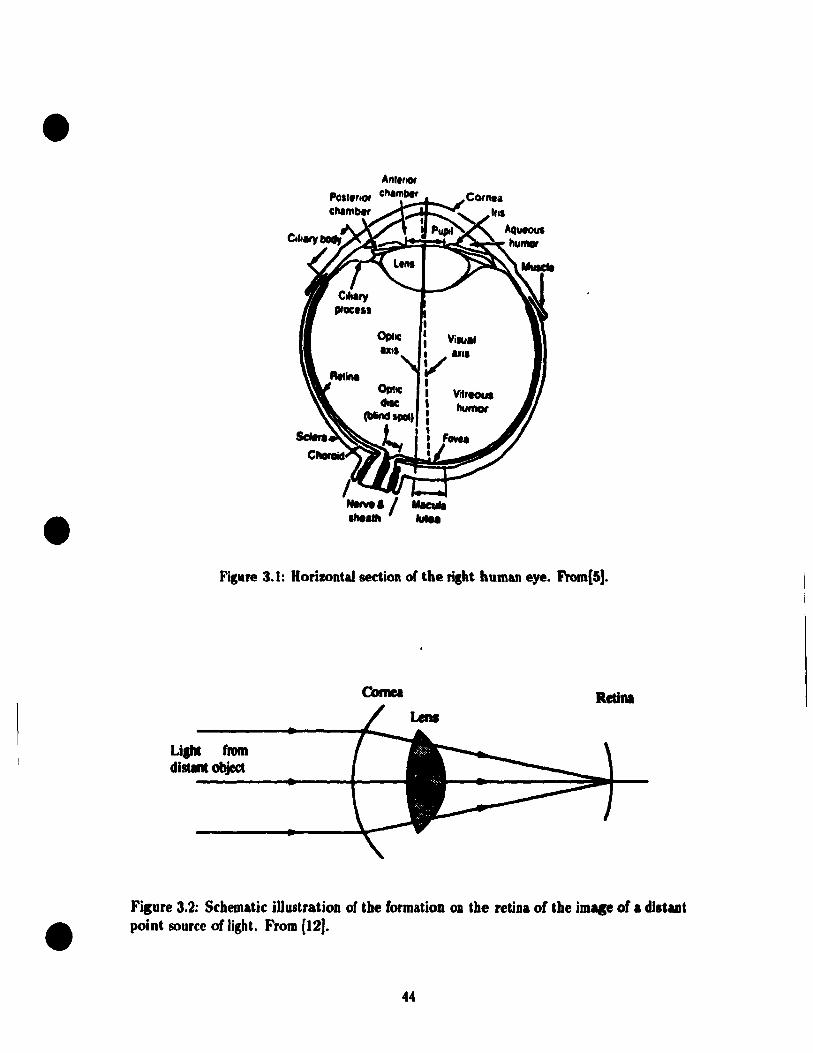
•
•
•
Figure 3.1: Horizontal section of the ri,ht human eye. From(5J.
Li'" (mm distant abject
Red ...
Figure 3.2: Schematic illustratioD of the formation OD the retiDa of tbe imace of • di.'ut point source of light. From (12).
44

•
•
•
1.'
f , .. , t.' ... t. •
-1 - -, • , t 1 • • Lee ............... ~ • ........ ..,....., ..
Fipre 3.3: Visual acuity Il a function of background luminance measured with a I.andolt-C t.arpt (1 observer) and square-wave sratins (2 observers). Dat.a are averages across one observation at each of (our orientations; observer. dark-adapted for 20 min. From [.J.
The aperture of t.he optical .ystem of the eye is controlled by an iris that forms a pupil
of 7 to 8 mm diamet.er in dark conditions t.o a minimum of about. 2 mm in a hiSh luminuœ
level. The diff'ract.ive efl'ect due to the smaU size of the pupils sets the hishest acuit.yof
the human eye, which is bued on the RayleiSh criterion. Considerins other factoR, luch
u luminance level, tarset contrast, location of the target on retina, etc., the human vilual
&Cuit.y islower than that set. by the Rayleigh criterion.
3.1.2 Viaual Ac:uity
This section discUSBeI fadon afl'ectins human visua! &cuity. Visu al &cuit y is lhe ability lo
resolve spatial detai)' Decimal acuity is expressed as the redprocal of the smaJlest pattern
or pattern detail (in minutes of arc of visual angle) that can be detected or identified at the
siven viewins distance. The factors afl'ectins the visual &cuit y mainly include luminance
level and contrast, target location on visual field, and viewing distance.
Luminance Levet and Tarlet Contrast
Figure 3.3 [.] shows that 1) visual acuity improves with increasing luminance and 2) acuity
approaches an asymptote at a luminance of 40 - 1000 Cdlm2, depending on the type of
tarset used. Usually most monochrome CRTs are capable of area brightness in excess of
300 Cdlm2• The brightness of an LCD depends on the light source il modified. A color 2.7
in. LeD Sony Watchman has a luminance from 150 Cdlm2 to 220 Cdlm2• Usually corrent
45

•
•
•
f 1.'
•••
A,+-~~--p-~-r~ __ ~ -JO 0 10 20 30 40 50 .,
CI)
DiJIInce oITilpt Iran F'IUIÏOII Cde..-)
J 'f ,. ,-
Il
IS
"
S
-10 0 10 20 30 40 50 .,
(b)
DiIllllCe 01,...". FiulianC .... )
Fipre 3.4: Visual acuity aB a function of tarlet distance from fixation. (a) Decimal acuity. Three difl'erent tarsets were used: Landolt-C rinp at a b&\kpound luminance of 2.46 tAl/rra2
(open drdes)j Landolt-C rinSI at a backlround luminance of 245 cd/m2 (dose circlel) and sine-wave sratin. (squarl.!fl). For the Landolt-C tarset, &cuit y is the r«iprocal orthe width (in minutes) of the small, ... t sap that can be localizedj for the patinl tarlet, acuity is the r«iprocal of the width (in minutes) of one bar of the finest patinl that is resolvable iDto bars. (b) Minimum ansJe of resolution (rec:iprocal of dec:imal acuity) for the three tupt •. From (19).
displays can provide enough luminance, and are not a factor afl'ec:tinl visual acuity.
Studies also show that, at a given luminance level, &cuit y increases as tupt contrut
or tarset exposure duration increases [2].
Tarlet Location in Vilual Field
Figure 3.4 shows that for photopic (daylight) levels of iUumination (> 0.03 Cd/m2), the
acuity of the human eye decreases fiS the target distance from the fixation point (retinal
eccentricity) increases (19). Two useful conclusions can be drawn from Figure 3.4 .
• The minimum angle of resolution at a field angle of 30 degrees is about 5 minutes.
Considering other factors that may dec:rease the visual &cuit y, a lateral color criterioD
of less than 7 minutes is reasonable.
• The fact that visua! &Cuit y at the center of the visua! field is much higher than that OD
the pcriphery sugests that it is acceptable for an optical device to provide the humUl
46
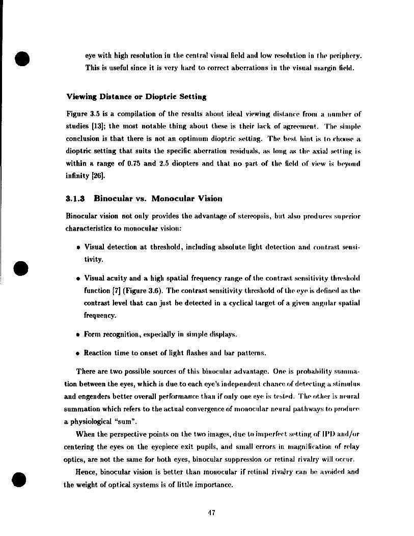
•
•
•
eye with high resolution in the central visual field and low resolution in th" p('ri"lwry.
This is useful since it is very hCird to correct aberrations in thl' visual nlélrgin fil'Id.
Viewing Distance or Dioptrie Setting
Figure 3.5 is a compilation of the r('sults about ideal vi.'wing dist.ann' from a IIlImb.'r of
studies [13]; the most notable thing about. these is thcir lack of agrt'('l1wnt. Th(' sim"I(,
conclusion is that there is not an optimum dioptrie seUing. TIlt' I)('st. hint. is tn d\Ons(' a
dioptrie setting that suits the specifie aberration residuaJs, as long as tilt' élxiaJ S(,tt.jllg is
within a range of 0.75 and 2.5 diopters and that no part of t.h.' field of Vil'W is l'''ynlld
infinity [26].
3.1.3 8inocular vs. Monocular Vision
Binocular vision not only provides the advantage of stert'opsis, but also prod,,,'('s slllwrior
characteristics to monocular vision:
• Visual detection at threshold, including absolu te light deteftion and ('Ontrast. s.'nsi
tivity .
• Visual acuity and a high spatial frequency range of the cont,rast smlRitivity thr('shnld
function [7] (Figure 3.6). The contrast sensitivity threshold of tilt' l'Y.' is d('fined aH t.hf~
contrast level that can just be detected in a cyelical target of a givcn él.lIglllar s')(ltial
frequency.
• Form recognition, especially in simple displays.
• Reaction time to onset of Hght flashes and bar l»attCI'JIR.
There are two possible sources of this binocular ad vantage. Or ... iR prohahilit,y SUIII/IIét
tion between the eyes, whieh is due to each eye's indc,)end .. nt chall("(~ of d(!t.(·cti"g a Ht.illllJllJli
and engenders better overaJl performance than if only one cyl' is t.·~t,·d. TI ... ottlf!r is lIf'IIral
summation whieh refers to the actual convergefl(:e of monotular rwuraJ ,)athwaYH t.n produ('f'
a physiological "sum".
When the perspective points on the two images, due tn irnlwrf.·f't sf'Uillg of IPI) and/or
centering the eyes on the eyepiece exit pupils, and small errors in magnifi.'atioll nf f('lay
opties, are not the l'lame for both eyes, binocular sUJ,pression or retinaJ rivalry will OCf'Uf.
Hence, binocular vision is better than monocular if retinal rivalry cali h,! avoidmJ and
the weight of opticaJ systems is of Httle importance.
47
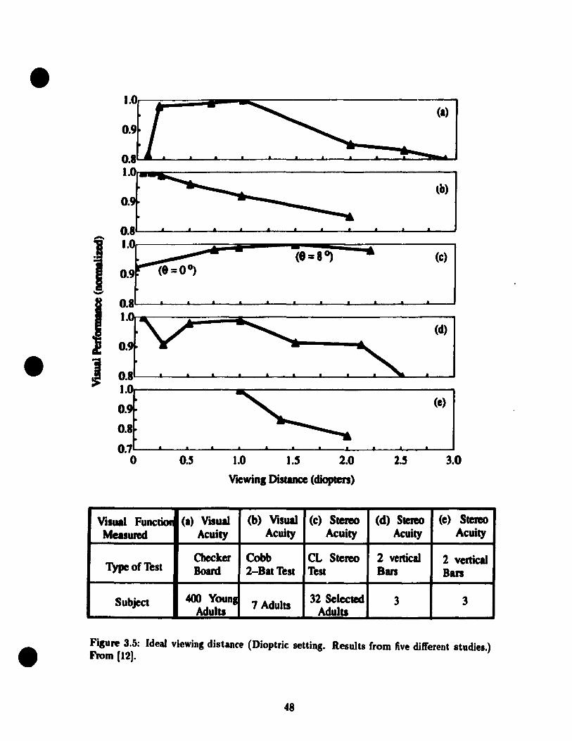
•
•
•
(a)
tb)
0.8
, 1.0 -- - (e=8~ (c) ~
0.9 r (8=0°)
-
1 0.8 • .L . . 1.
(d)
O .
J (e)
0.8
0.7 0 0.5 1.0 1.5 2.0 2.5 3.0
Viewinl Distance (diopten)
Visual Func:lÏOI1 (a) V .. uaI (b) Visual (c) Stereo (d) Stereo (e) Stereo Measwed Acuity Acuity Acuity Acuity Acuity
Checker Cobb CL Stem» 2 vertical 2 vertical Type of Test Board 2-BatTest Test Bars Ban
Subject 400 Younl 7 Adults 32 Selected 3 3 Adults Adults
Fisure 3.5: Ideal viewins distance (Dioptrie: settins. Results (rom live difl'erent studie •. ) From (12).
48

•
•
•
)JI 2.0
• 15 ii '.0
(1'
500
• . .... ".,.. 200 Q .11 .... ' ... -
l' •• Lili'"
100
50
20
'0
5
- " 2 " " " , " 0 20 • 10
(b)
1_" ,'"u .... , .c,c' •• "",,,,
Figure 3.6: <a> Ratio of binocular to mean monocular sensitivity and (b) binocular versus monoeular contrast sensitivity. Note logarithmic axis. From (3) .
49
•
•
•
3.1.4 Wide Instantaneous Field or Vie •
The normal, achromatic field-of-view size for a human observer is approximately ±l00o
horizontally and ±6(yJ vertically. A large IFOV of HMDs aUows operators to use both head
and eye movements to search large portions of the operation area. Eye movements are faster
than 'I('ad movemmlts, and coordination of the head and eyes to acquire visual targets is a
much-"rartisf>d and well-coordinated activity. In addition, a large IFOV afl'ords operators
the Us(~ of their peripheral vision. In contrast, with small IFOV, the head and eyes have
to ,wint to the same direction for operators to extract the same information. Therefore,
the synNgistic effect of the eye movement is lost. Moreover, peripheral vision provides less
information if Hw IFOV is smaller.
A Il Mf) wilh a wide IF'OV not only gives operators a realistic sensation of telepresence,
but. also has tf\(' Jume'it of l'nhancing safety and increasing efficiency. A study conducted
by M .. " W(·lIs and M. Vent.urino [35] showed that
J. redudng the size of IFOV of a HMD reduced performance at a search and shoot task,
as nwa.')ur(!d by the number of threats hit and the time for which the operator was
threatcllf>d, and
2. the minimum IFOV required to achieve optimum performance increased with increas
ing complexity of the task.
TIIC! fonclllsion is that an advanced HMD should have a wide IFOV.
3.1.5 Color Vision
Color would enabl(· t.he viewer to bett~r discriminate different types of objects, giving, in
additioll t,o the normal morphological information of a monochrome display, the cues of
('01 or . nut human colnr vision cannot make an objective determination of true color. A
uniformly mlored bafkgroulld, after awhile, will look like white-grey to the human eye.
Thlls if rolor W('f(' IIsed to code an ('vent, its accurate identification could be difficult.
3.1.6 Summary
This s('ction disclIssed the hllman eye characteristics relative to the design of advanced
IlMDs. Tlw disfllS'iions sllggest. that an advanced HMD system should have binocular
(st('r('o) vision, color vision, a wide IFOV, adequate contrast ratio and luminance level,
r('éu.;onable image location setting, and sruaU aberrations .
50

•
•
-4 -1 0 2 •
le ............................ , •• ,"' •• .,.,
Filure 3.7: Averase monocular and binocular pupil diameter al a fundion of luminance level. From (23).
3.2 Geometry Factors
1.2.1 Pupil Si.
The diameter of the pupil of the eye varies from 8 mm to 2 mm with the level of illumina
tion and is smaller when both eyes are iUuminated than when only one is iIIuminated (23)
(Filure 3.7). In the daytime, the diameter of the eye is around 4 mm.
The eyeball pivots in its socket about a rotation center which is 10 mm behind the
entrance pupil (Fipre 3.8). For normal, unaided viewinl, the comfort Iimit for eye rotation
from strailht ahead il about 40 degrees [12]; however, the observer may avoid approachinl
this Iimit by rotation of the head. The positions of the optical relay of a binocular HMD
system with respect to the helmet remain unchanled when the pupil positions vary. This
places a demand on display optics to have exit pupils much larger than the nominal pupil
size (see Figure 3.9). Assume that the eye rotates by the angle 0, the radius of eye pupil
is r and the radius of rotation is R, then the diameter of the exit pupil for an unvignetting
margin field is
D = 2·(Rsino + rcoso) (3.1 )
Assume that the eye usually rotates within ±20o, and the pupil diameter of the cye i8 ...
mm (Figure 3.9), then the diameter of the exit pupil is
D = 2 x (10 x sin 20° + 2 x cos 20°) = 10.60 mm (3.2)
• The optical relay of the BLHMD has an exit pupil of 10 mm. Please note that optical
quality ",iD be measured by the quality within the eye pupil, not the display pupil as a
51
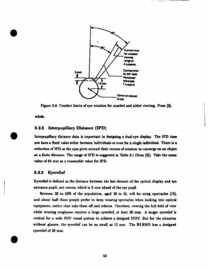
• COtIllon ""'" fotUftIIdH WIeWIftt. ,.,..., ...... eom"" lIIfIII far.S· .....
-::::::z~~~r ---IIIOftOCuII, .., .... ICIIPI.
7sub,ecl.
____ Ce",., O. fOIlllOft
or.,.
Fisure 3.8: Comlort Umits 01 eye rotation for unaided and aided viewins. From (3).
whole.
S.2.2 Interpupillary Distance (IPD)
• InterpupiUary distance data i. important in desipins a dual-eye display. The IPD does
Dot have a fixed value either between individual. or even lor a sinlle individual. There i. a
redudion of IPD 88 the eyes pivot around their centers 01 rotation to converse on an object
at a finite distance. The rUlse of IPD i. sugested ÎD Table 3.1 (from [3)). Take the meu
value o( 63 mm as a reasonable value (or IPO.
•
3.2.a Eyerelief
Eyerelief is defined as the distance between the last element oC the optical display and eye
entrance pupil, not cornea, which is 3 mm ahead oC the eye pupil.
Between 30 to 50% or the population, aged 20 to 45, " .. m be usins spectacles [12],
and about half those people prefer to keep wearing spectacles when looking into optical
equipment, rather than take them off' and re(ocus. Therefore, \'iewing the full field of view
while wearins eyeg)asses requÎres a large eyerelieC, at least 20 mm. A larger eyerelief i.
critical for a wide FOV visua! system to achieve a designed IFOV. But for the situation
wïthout glasses, the eyerelief can be as smalt as 12 mm. The BLHMD has a designed
eyerelief of 20 mm.
52
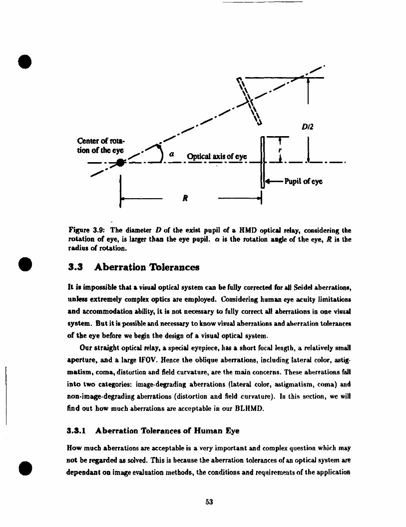
•
•
•
0/2
, 1 -1 ______ .
R
Figure 3.9: The diameter D o( the exist pupil o( a HMO optical relay, .:onsidering the rotation of eye, is larpr than the eye pupil. Q is the rotation ansle of the eye, R is the radius o( rotation.
3.3 Aberration Tolerances
ft i. impossible that a visua! optical system .:an be (uUy .:orreded (or ail Seidel aberrations,
unless extremely complex optics are employed. Considering human eye acuity limitations
and ac.:ommodation abillty, it is not necessary ta fully correct all aberrations in one visual
system. But it is possible and necessary ta know visual aberrations and aberration toleranees
of the eye before we begin the design of a visua! optkal system.
Our straight optical relay, a special eyepiece, has a short (ocallength, a relatively small
aperture, and a large (FOV. Hence the oblique aberratioRs, including lateral color, astig
matism, .:oma, distortion and field curvature, are the main concerns. These aberrations fan
into two categories: image-degrading aberrations (lateral color, astigmatism, coma) and
non-image-degrading aberrations (distortion and field curvature). In this section, we will
find out how much aberrations are acceptable in our BLHMD.
3.8.1 Aberration Tolerances of Human Eye
How much aberrations are acceptable is a very important and complex question which rnay
not be regarded as solved. This is beeause the aberration toleranees of an optical system are
dependant on image evaluation methods, the conditions and requirements o( the application
53

•
•
•
Percentile Rank
Number Group in Sample 5 50 95 SD Ref Aviators 4057 57.7 53.2 69.9 3.6 [16] Army drivers 431 54.1 58.9 64.0 3.0 [9) ( white) Army drivers 79 57.9 62.0 71.7 3.8 [9J ( black) Army & Air Force 3205 51.0 - 65.0 - [1] ( Ii~males)
sn = standard deviation of measuremeut within the group
TéLble 3.1: Interl'upillary distance for different groups, based on observations taken from military per:iOlIlJ(l1. From [a].
of the syst.em, and the characteristics of the receiver (such as human eyes) following the
syst .. m.
PI('a.o;e not.e that the use of the word "tolerance" in this connection does not carry the
saine go, no-go connotation that it does in matters mechanical where parts may suddenly
('('ase to fit or f\lnction when tolerances are exceeded. Any amount of aberration degrades
t.h .. images; a larg('r am01\llt simply degrades it more.
Rayleigh Criterion
Alth()ll~h b('ing f('lated to each other, directly or indirectly, various image evaluation ap
proad\('s, sllch as th(' Rayleigh criterion, modulation transfer function (MTF), and image
flll('rgy dist.ribut.ion, are from different viewpoints, and their applications are alllimited to
part.irula.r opt.iral syst.ems. For cxample, t.he MTF is widely used to describe the perfor
malle(' of a lens system, but it has been shown that the MTF is not a useful quality test
for vistml opt,i('al hyst.('ms [6]. Of thcse methods, the Rayleigh criterion is practical and
(·onwlli(lnt.. Th<, nayl<,i~h criterion employs optical path differellce (OPD) to evaluate im
a~('s, and 0 PD has dir(lct and simple relations with Seidel aberrations. Hence, aberration
loler.uH·(\S can tH' obtahll'd from t.he Rayleigh criterion.
Ail illlag<, point. may he thought to be formed hy a spherical wave. When the actual
imag<' I)(}int d<'parts from tlll' id(lal or r"ference point, the maximum departure of the actual
spherical wave front from an ideal sphere is often referred to as peak-to-peak of peak-to
vall('y (P-V) 01'1>. If tltt' wavt' front is irregular, the root-mean-square (RMS) OPD is a
54

•
•
•
better measure of the effect of the wave-front dl'f~rmation. RMS OPD is 'ht' S(lUit!'(' root of
the mean of the squares of ail the OrD values over the full apcrt.ur(' of iUl optkal systl'III,
For the detailed derivation of the relation betwel'11 abNrations and OP)) S('(' [19, I)é\~t'S :tn
- 339].
The Rayleigh criterion allows no more than onl'-quartN wétVt'lt'lIgth of OPI> nVt'r Ill('
wave front with respect to a reference sph('r(' about a selt'ctl'd imagl' point, in onl('r t.hat. t.h(,
image may be sensibly perfecto
The following tabulation [29] indicates the amonnt of irnagt'-d('gnuling aht,. rat.ion ('OI'ft'
sponding to one-quarter wavelength of OPD when t.h" f('fen'.u'(' point. is dIOS('1I '0 lIIinimizl'
the P-V OPD.
ose
Lateml colm'
Astigmatism
0,5'\
Il' NA ..\
NA ,\
(:1.:1 )
(:1.'1 )
(:1.1';)
(:Ui)
where ..\ is the wavelength of the Hght., n is the index of the mt'dillm in whkh tilt' illlap;(' is
formed, Um is the slope angle of the marginal axial ray at the axial imag(!, NA = 11 sill (1", is
the numerical aperture, and H' is the image height. In the nLHMU sysll'IlI,..\ = 5;,(){) ïl =
5.5 X 10⁻⁴ cm, n = 1, Um = 30°, NA = 0.5, and Il' = 25 cm, From tht· f'quiI.t.ioIlS ahoVf',
we obtain
ose 2.2 x 10⁻⁵
Lateral Color 2..\
Astigmatism = ... ..\
(:J,7 )
(:I.X)
(:U))
Experimental studies of the eff('ets of Seidel aberrat.iolls (prirna,ry d"fOf'lIs, spllf'lÎcal
aberration, astigmatism, and coma) on visuaJ targ(!t disnimirHltioll hy !J"I'1.011 arHI Hilip; [fi] . determined the threshold values of t.he human visual sy~tf'ln to ,lirfpn·lIt. 1'!VI'h, ami roUI hi
nations of the aberration types by a forccd-choiœ disl riminal.ioll lt'chrlÏllul', TIH' "·hlllt.illg
threshold levels, expressed in unit!> of wavelcngth, sJ)('cify t hf' l'hangf'h III Wil VI'- front. il IU'r
ration that can be detectcd with sorne defined prohahility and f(!pn·!>f·nt. JIl'l/-Twti""fllJl,·
differenœs in image quality. The results agrc('(J weil witt. the Haylpigh nitnioll, Tahl.· :1.2
shows aberration values that could he di!>crirninated in high contrahl. tarP/'t.h al 75% proh-
sr,

•
•
•
AbNration OPD Level Level Allowing for Refocusing Sptwrkal A b(~rration 0.21 A 0.67 .\ Coma 0.46 A 0.46 .\ Astigmatism 0.30 A 0.39 .\ Defoflls 0.22 A -
Tahl(· 3.2: Visual aberration values that could be discrirninated in high contrast targets at 75% JHobability h·vels. From [6].
ahility lev(·IR.
Th(~ irnagf~-d(·gra.ding aberration tolerances shown above, whether derived frorn the
Hayl(!igh rriterion or from eXI)eriments, only are the image-degrading aberration values in
wav(!- frollt "that can b(' detected with sorne defined probability and represent just-noticeahle
diffNell(·(,.; in image (Juality" [6]. 'J'hese values are ouly suitable for optical systems with
slJIali aherrations Sil ch as objectives of telescopes and microscopes. ft is extremely difficult
t,o ('Orrert. a, systf:'1lI to this lev('l of quaJity over an appreciable field. Most optical systems
(!x('('('d this aJlowaltc(' rnauy times over.
For 0J)tkal systems with large aberrations exceeding the Rayleigh criterion many times,
g('()lJletrÎfal image ('ner!;y distribution may be used to predict the appearance of a point
ima.g(' wit.h a fair d('grec of accuracy. It is diffirult to attempt to derive the aberration
tol('ranr('s of the humait ey(' based on thoory because of the coherent coupling hetween the
optks altd th(! eye, and the non-linear b('havior of the latter.
As for non-image degrading aberrations, field curvature and distortIOn, only emprical
ab('rrat.ion tolerances can he found [26, 33, 19].
ln short, the aberration tolerances for the optical relay can he summarized [26, 33, 19]:
• Di!>tortioll: I('ss than b "" 10%.
• Latt,fitl color: less than 5 f'V 7 minutes.
• Field ('lIrvaturl': the tangential field curvature lies within 0.9 diopters of the central
imagt· p1all(', the sagitt.al field within 3 diopters, and no part of the fields is beyond
infinity.
• Astigmat.ism < 2 dioptl'rs.
• Coma: ose is less than 0.0025 .
56

•
•
•
3.4 Optical Design Criteria
In this chapter, we discussed the characteristics of the humait t>y<', whkh has a s<'parllt.'
optical system and retina to receive and form an imagt> of a seent>. It has h."'11 showlI t ha t,
use of two eyes allows a beUcr perception of depth and ail improv('lIwllt ill vislHll at'uity.
Color images present more information than monochromie 1It>IICt, ("olor sh'n'o visioll will 1,..
more acceptable for human eyes than mOllocular and 1ll0norhronH' vision. BéU;(,<I on t Il('s('
discussions, we believe that an advanced IIMD should have billo('ular (Sh~f('O) allet ('Olof
vision.
CORsidering factors affecting visual acuity of an eye, sllch as tuminallc'(' I('vel, l"Ontrast,
retinaI location, and viewing distance, the ideal conditions that a visual syst'('1II Ilrovidl's to
the eye are adequate luminance (40 - 1000 Cdlm2 ), high rontrast, high n'solution 011 the'
central visual field, and reasonable dioptrie setting.
The following design criteria of the optical relay summarize the discussions of S.,(,t,ioll :J.2
and Section 3.3.1 on geometry factors and aberration toleranres of the huma.n visun.1 syst,.,,,,.
Optical Design Criteria
Human Factor
Constraints: • IFOV> 60°
• Diameter of lenses < 55 mm
• Eyerclief > 18 - 20 mm
• Diameter of the exit pupil > 10 mm
• Totallength of the straight oJ)ticai relay < 100 mm
• as light as possible
51

• A twrraf.Ïon Tol{~r-
aru:es:
Othcr Constraints:
.'
•
.',
• \ 1.\
• Distortion on full field < 10%
• Lateral color < ,5 '" 7 minutes
• Field curvature: the tangential field curvature lies with
in 0.9 diopters of the central image plane, the sagittal
field within 3 diopters, and no part of the fields is he
yond infinity.
• Astigmatism < 2 diopters
• Coma: ose < 0.0025
• Ali spherical lenses
• Display size (41.1mm x ,54.4mm)
"
58

•
•
•
Chapter 4
Optical Design of HMD
4.1 Introduction
In Chapter 3, we discussed the desired charactcrist,ini of thl' IILIIMD opt.if,,1 1'('lay. Thh;
chapter determines the structural parameters, bas('d 011 UJ(' d('sign t.h(lolÏ('S disc'lIsst'd ill
Chapter 2.
Optical design is a process in which the desircd charact<'fistirs of ail opt,iral sYHI,PIII art'
given and the constructional parameters arc to be determincd, A larg(' part of optiral d('sigll
is concerned with analysis of the system. Figure 4,1 is a simpl .. dlart of tht' pro('C'SS,
For computer aided lells design, th<'fe arc sev(!ral Stf.'pH to follow. 'l'lU' firHt alld vl'I'y
important step is to choose a Iikely starting system. Th(!f(! is 110 sure J)ro('(·dlll'f' thal. willl('ad
(without forekllowledge) from a. set of characteristirs to a suitahle Htartillg dl'sigll, tJ:illallv
a Iikely starting approach to the desired lens rail b(' ohtaillcd hy ('it/U'I' a lllI'lIt.al glll'SS W •• ,I'II
may work weil for an experienced design('r, or a searrh through pr(·viollr-.ly df'siglll'd If'IlSI'H
in patent files. The second step is to construct a JONit fUlldioll wllÏ( h dl'Sf rihl'r-. ail d.·"in·"
characteristics, which are suitahly weighted a('(:ordillg to t/u'ir illlJ)()I't.<UIf'(I, 'l'hl' 1.Ir-.t r-.I.c'p ir-.
optimization of the lens accord in g to tll(' lII('fit fu nction alld i nitiaJ !-.titrti ng poi Il t. "1 fil os 1,
ail of the design work in this ther-.b wah carri .. d out 011 "ceos V, a l''flh dl'hiJ!,fI hoft.wal'f· hy
Optikos Corporation, New York.
This chapter first reviews the (h!sign history of thl' BLiI M /) opti( ,II n'/dY, thl'II fOI Uhflf,
on two types of approaches to t1w ULtIMD optif'a/ rl'/ay, htraight ami fo/dl'I/ dl'higllh, Ih.bil
design considerations and design procedures arc discllhsed, Th" rl'hu/tant 111'r-.igflh aJl(I thl·if
analyses arc also presen ted.
,1)9
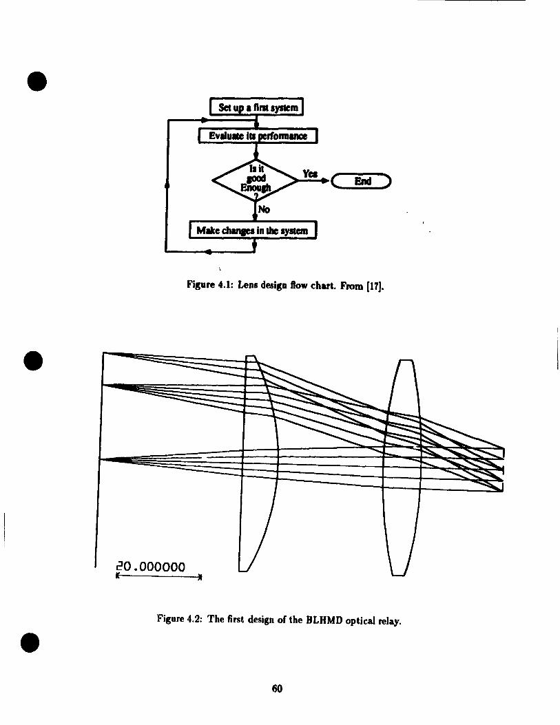
• Set Up 1 Hnt system
~~( End )
Mike cJIanaes in the system
Fisure 4.1: Lens desisn ftow chart. From [17J •
•
20.000000 1 •
Figure 4.2: The first design of the BLHMD optical relay .
• 60
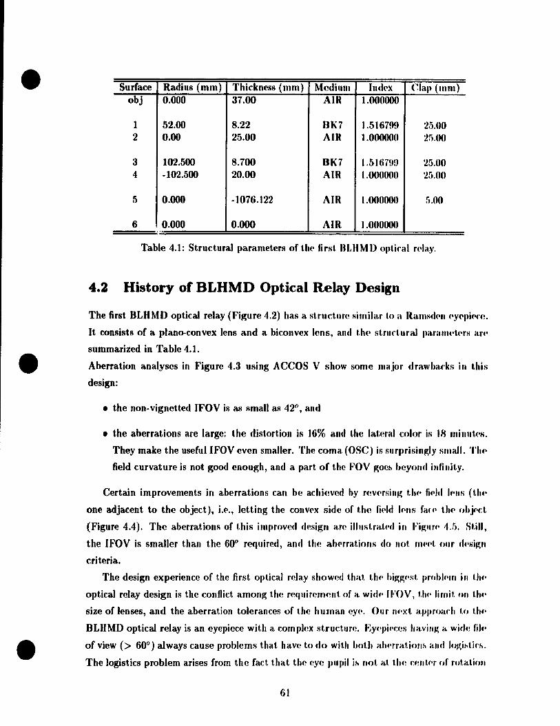
•
•
•
Surface Radius (mm) Thickness (mm) Medium Indl'x Clélll (mm) obj 0.000 37.00 AIR 1.000000
1 52.00 8.22 8K7 1.516799 25.00 2 0.00 25.00 AIR t .ooonoo 2il.OO
3 102.500 8.700 8K7 1.5Hi7H9 25.00 4 -102.500 20.00 AIR 1.0OO(KlO 25.00
5 0.000 -1076.122 AIR 1.000000 ii.OO
6 0.000 0.000 AIR 1.000000 .-
Table 4.1: Structural parameters of th(' first nUIMD 0l,tiral n'Ia.y.
4.2 History of BLHMD Optical Relay Design
The first BLHMD optical relay (Figure 4.2) has a structure sirnilar t.o a Rarnsd('fl ('Y('J,i('('(~.
It consists of a plano-convex lens and a biconvex Itms, and UI(' strurt.uraJ J,a.ra.nl('tNs an'
summarized in Table 4.1.
Aberration analyses in Figure 4.3 lIsing ACCOS V show sorne major drawh.u·ks in t.his
design:
• the non-vignetted (FOV is as small as 42°, and
• the aberrations are large: the distortion is ]6% and the lateral color is IR millut(·s.
They make the useful IFOV even smaller. The coma (OSe) is surprisin~ly small. Th.·
field curvature is not good enollgh, and a part of the FOV goeh heyond illfinit.y.
Certain improvements in aberrations can be aclli(!ved by r(!vNsillg t.hp fi"1d 1"lIs (th(·
one adjacent to the object), L('., letting the conv('x side of the fi(·ld 1f'IIS fa( C' li ... ohj(·(:t.
(Figure 4.4). The aberrations of this improved desigll are il/uslrat('d in Fi~uf(' ".f). St.iII,
the IFOV is smaUer than the 60° required, and the abNrations do Ilot m('('1, ollr d(·sig ..
criteria.
The design experience of the first optical reJay showed that U ... higg(·st. probh'UI in Ulf'
optical relay design is the confliet among the re(luiremenl of a wid,· 1 FOV, t/u· lirni" Ofl th(·
size of lenses, and the aberration tolerances of the human cy(·. Our IIf'xl approadl 1.0 Ulf'
BLHMD optical relay is an eyel,iece with a complex structuf(!. EY('piN:es having a widf~ fil(·
of view (> 60°) aJways cause probJems that have to do with hoUI atH'rratioflh itnd logi"tiff •.
The logistics problem arises from the fact that the eye pupil ih flot al th,! ,:mltN of rotat.ion
61
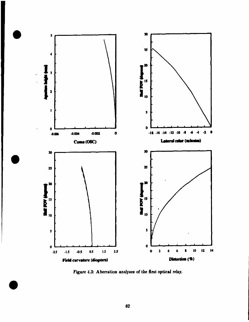
•
•
•
, -----------.
4
), 1 J'
o ~~-~-----~~--~ .o." .o.OIM .o.cm o
c .... (OSC)
5
.2.5 .1.5 ·CU 0,5 1.5 2.5
Field c.r .... 1'f (diopten)
.11 .l6 .14 ·12 ·10 ·1 " .. ·2 0
o 2 4 6 1 ro u "
Figure 4.3: Aberration analyses of the fint optical reJay .
62
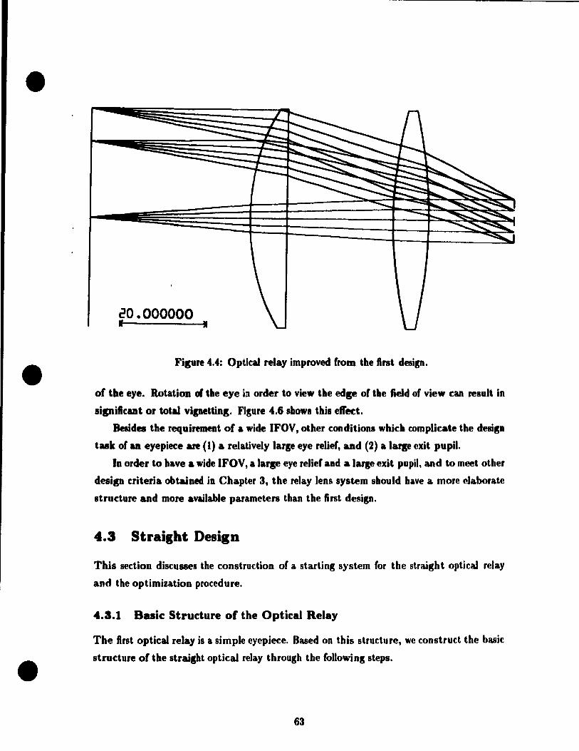
•
•
•
---- ----------------------------
20.000000 • • Fipre 4.4: Optical relay improved from the first desi", .
of the eye. Rotation fi the eye in order to view the edp of the field of view .:an result in
sipificant or totù vipettins. FiKure 4.6 showi this efl'ect.
Besides the requirement of a wide IFOV, other conditions whi.:h compli.:ate the desisn
task of an eyepiet:e are (1) a relatively larse eye relief, and (2) a IUle exit pupil.
border to have a wide IFOV, a lar. eye relief and a Jarse exit pupil. and ta meet other
design criteria obtained in Chapter 3, the relay lens system should have a more elaborate
stradure and more available parameters than the first design.
4.3 Straight Design
This section discusses the construction of a starting system for the straight opticaJ rclay
and the optimization procedure.
4.3.1 B •• ic Structure of the Optical Relay
The first optical relay is a simple eyepiece. Oased on this structure, we construct the basic
stradure of the straisht optical relay through the foUo.·inS steps .
63

•
•
•
,
41
1, 1 J.
0
25
1" 1 110
5
0
5
0
o.a O.OIN O." -1' -16 -14 -12 -10 .. -6 ~ ·2 0
C .. (OSC) ...... eoIar( ...... '
\ , \ \ \
1" \ \ \ 1 \ \ 1
10
5
o 2 4 6 • 10 12 14
Field ~u,.. •• ure (diopltn)
Figure 4.5: Aberration analyses of the improved first optical relay desip .
64

•
•
•
Center
Oprical axis of eye ~ ~........ "---.:-.' "-
Center of rotation
.,
Fipre 4.6: The logistic8 problem with wide IFOV eyepieces. Rotation of the eye to vie" the edp of FOV may lose aU of the pidure.
Step 1 Replace the two sinlle lenses with two doublets to control the lateral color. This
type of eyepiece, consistins of two doublets, is called the military eyepiece (17).
Step 2 Insert a biconvex element between the two doublets as a relay su ch that mUlÏnai
raya of the wide field still can pus throup the doublet near the eye (called tlle eye
lena). Thua the system can achieve a 6()0 IFOV. Meanwhile, aince the biconvex lena
shares part of the power of the eyepiece, it should weaken the inner convex surfaces
of the two doublet. to lEeep the sune focallensth. This reduces aberrations u weil.
This type of eyepiece is the ErIe eyepiece patented in 1921 by H. ErIe [11).
Step 3 Add a positive meniscus lens right after the eye lens to increase the eye relief. The
reason for this is explained in the next section.
The basic structure of the startins system thus consists of four elements: two doublets, one
biconvex lens and one meniscus lens. The thickness and the optieal material of eatb leos,
and t!',e power distribution amons the lenses, remain to be determined.
4.3.2 Further Considerations
For an eyepiece of a given focallength, it is desirable to make tbe eye relief as large as
possible. This can be realized by concentrating the convergent power in the clement or
elements nearest the eye, and reducing the power (or even rnaking it negative) in thœe
adjacent to the object [27]. This ac:tually pushes the principal points toward the eye and
the exit pupil plane right a10ng them. That is why a positive meniscu8 lens is added right
after the doublet neu the eye. Meanwhile, the power of the doublet adjacent to the object
65
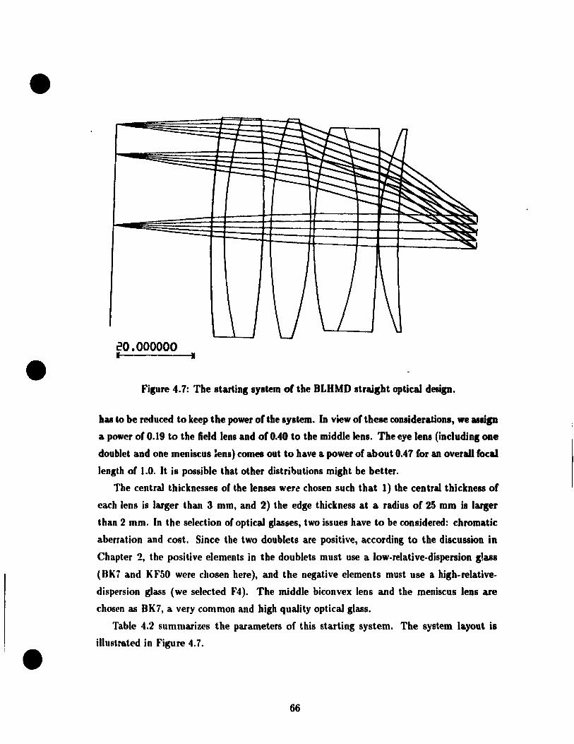
•
•
•
20.000000 1 •
Figure 4.7: The starting system of the BLHMD straight optical design.
has &0 be reduced to keep the power of the system. In view of these considerations, we "Iip
a power of 0.19 to the field lens and of 0.40 to the middle lens. The eye lens (including one
doublet and one meniscus 1ens) comes out to have a power of about 0.47 for an overall focal.
length of 1.0. It is possible that other distributions might be better.
The central thicknesses of the lenses were chosen such that 1) the central thickness of
each lens is larger than 3 mm, and 2) the edge thickness at a radius of 25 mm is larger
than 2 mm. In the selection of optical glasses, two issues have to be considered: chromatic
aberration and cost. Since the two doublets are positive, according to the discussion in
Chapter 2, the positive elements in the doublets must use a low-relative-dispersion gtass
(BK1 and KF50 were chosen here), and tbe negative clements must use a higb-relative
dispersion glass (we selected F4). The rniddle biconvex lens and the meniscus lens are
chosen as BK7, a very common and high quality optical glass.
Table 4.2 summarizes the parameters of this starting system. The system layout is
iUustro.ted in Figure 4.7 .
66

•
•
•
4 r---------------~----~
u
,
0.5
o ~--~--~-~------~ .CUD. .0.0001 .0.CII06 .0.0004 .0.0002 0
C .. I(OSC)
35 --------------------,..
1
1 1
1
1 .. 1 1 1 1 1 1
1.5 1
.0 , , 5
.2.5 • •. 5 .0.5 0.5 1.5 2.5
Field eurvatuft (diopten)
35 r----------------_
1 .. 1.5 1
.0
5
.24 ·30 ·.6 ·12 .• -4 0
:J5 -------------
1 .. 1.5 1
10
5
o 2 4 6 a 10 12 14 16
Figure 4.8: The aberration analyses of the starting system of the straight optical design.
61
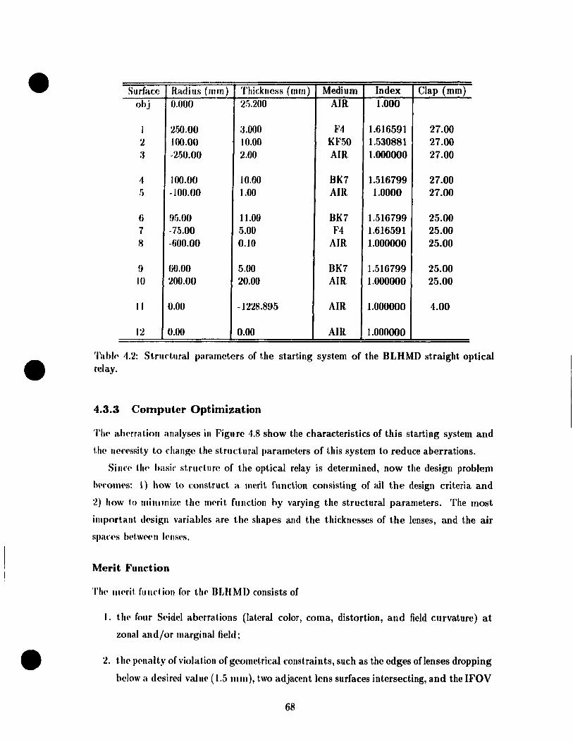
•
•
•
Surface Radius (mm) Thickness (mm) Medium Index Clap (mm) obj 0.000 25.200 AIR 1.000
1 250.00 :J.OOO F4 1.616591 27.00 2 JOO.OO 10.00 KF50 1.530881 27.00 :. ·2.1)0.00 2.00 AIR 1.000000 27.00
4 100.00 10.00 BK7 1.516799 27.00 5 -100.00 1.00 AIR 1.0000 27.00
6 !)5.00 Il.00 BK7 1.516799 25.00 7 -75.00 5.00 F4 1.616591 25.00 8 -(,00.00 0.10 AIR 1.000000 25.00
9 (jO.OO 5.00 BK7 1.516799 25.00 10 200.00 20.00 AIR 1.000000 25.00
Il 0.00 -1228.895 AIR 1.000000 4.00
12 0.00 0.00 AIR 1.000000
'l'itbl(\ 4.2: Structural parameters of the starting system of the BLHMD straight optical rclay.
4.3.3 Computer Optimization
'l'h(\ alwrra tiOIl analyses in Figu re 4.8 show the characteristics of this starting system and
t.!\(' IH\('(\ssity to ('hange the structural parameters of this system to reduce aberrations.
Sillc(\ t.lJ(' ha sic strudure of the optical relay js determined, now the design problem
IWfonws: 1) how 1.0 consl.ruct a. merit function consisting of ail the design criteria and
2) how 10 miIlllnize the ml'rit fUllction hy varying the structural parameters. The most
important. d('sigll variables are the shapes and the thicknesses of the lenses, and the air
SpélC(,S l)('t.w(\(\11 lt'nses.
Merit Function
Th(\ lI\('rit. f\lllclion for thl' DLHMD consists of
1. the four Seidel aberrations (lateral color, coma, distortion, and field curvature) at
zonal and/or marginal field;
2. Ut(' p(\llalty of violat.ion of geometrical constraints, such as the edges oflenses dropping
helo\\' a desired value (1.5 mm), two adjacent tens surfaces intersecting, and the IFOV
68

•
•
•
becoming less than the assiglled value; and
3. the departure of the location of thp final virtual imag(' from 1 he d<'sirl'd IO('al ion. This
helps to hoId the power of the optical relay, sine" the posilion of th., ohjt'd is fix.'(1.
The four aberrations are found according 1.0 th('ir d"finitions in ChaptN 2 hy lradllg
necessary rays through the system as follows:
• Lateral color: trace both C (À = 656.3ulII) and F (À = .186.11Im) I)rillripal rays from
the zonal object point (Y = 0.707 object. Iwight) throllgh 1.11(' sysh'lII, alld obtain t.1H'
slope angles (Je and (J/ betweell rays and optkal axis (l,t tilt' t'xit (lllpil (hnl h rays IIlllst
go through the r:enter of th(' exit pupil, sinee th('y are prin/ilml rays,), TIIf' diflè'rPlu'('
between these two angles is the lateral color for t h(' ZOll,tl point .. 'l'II(' latNal ('Olor for
the marginal point (Y = object height) is obtain('d in tlH' Séllll(' W,IY,
• Distortion: trace a marginal principal ray, and fintl t.l1(' Iwight of tht' inl,('rspd.ion
point on the final virtllal image plane. The departllre of thb valtu' fmm t.ht' paril,xial
principal ray height on the same final image plane is tilt' distortion a.!. th(' Illal'gillal
field. The percentage distortion is th(' ratio of dl(! distortion 1.0 t.l1(' "ara,xial prin( ipal
ray height.
• Coma: trace two rays from the zonal object point I,hrough th(' 1I1)I)('r and lowf'l' rilll of
the exit pupil separately, and obtain their J>oints of illtert-.cct.ioll with t.I)(, illlaw' plil,II('.
The distance of the middle point of thes .. two points (th.,sp tWH p"intl-. lIIay ('ollu'id(,)
above or below the principal ray is a direct nwasure of tallg('ntial ('0111,1, at th/' zOIwl
field. The marginal tangential coma may b .. found hy the S.UJlP way, Sagit.t,a.1 ('()lIIal-.
can be obtained by tracing sagittal rays through I.hl' front and ft'al' J'lili of t.h!' f'xil.
pupil. OSC is eClual to the sagittal coma divid(·cJ hy I.hp prindpal l'ay lu·iV;ht. 011 1.1 ...
image plane.
• Field curvature: trace two rays from thp same objc('t pnillt. dOl-.f! 1.0 1.111' "rilll Ipal my
through the whole system, then calculah! their point.:-. nf inl.pft,f'f,t.ioll 1/1 tJJf' Îlllav;!'
space from their &lope angles and positions at the ('xit pllpi!. T!1f' If'riprOf .11 of !JI/'
longitudinal distance in meters along the optical axit-. 1lf't.Wf!PII Hlf' imagp point. <llId
the exit pupil is the field Cllrvature in diopters.
The violations of geometrical contraints and th .. departure of ttlf' location of tlu' final Î1IlaW'
are regarded as aberrations, with difTerent weight& .
69

•
•
•
NAME SUItF(S) MODE VALUE TARGET WEIGHT FMTC CFG 1 IMD () '1'0 12 COR 1228.895432 1228.895432 1.000 O.OOE+OO EUGE :1 BYP 7.176244 1 .. 500000 5.000 O.OOE+OO EUGE 5 IJYP 8.631587 1.500000 1.000 O.OOE+OO EUGE t nyp 5.251691 2.000000 1.000 O.OOE+OO EUGE 2 BYP 4.823756 1.500000 1.000 O.OOE+OO ET>GE 4 IJYP 2.572064 1.500000 1.000 O.OOE+OO EI>GE 6 BYP 3.36? 192 1.500000 1.000 O.OOE+OO EI>GE 9 BYP 1.11l212 1.500000 1.000 O.OOE+OO PU PIL II BYP 4.000000 0.000000 1.000 O.OOE+OO YA2 12 HYP -0.589005 0.000000 1.000 O.OOE+OO VWA J2 COR -0.593481 -0.550000 100.000 1.89E+Ol YA4 12 BYP -0.598748 0.000000 1.000 O.OOE+OO 'l'(;OM 1 COR 1.766141 0.000000 2.000 1.25E+01 TCOM7 COR 0.102722 0.000000 2.000 4.22E-02 TAFCt COR -8.141370 0.000000 2.000 2.65E+02 'J'AFC7 COR -6.649082 0.000000 2.000 1.77E+02 SCOMt COR 0.256889 0.000000 2.000 2.64E-Ol SCOM7 COR -0.134102 0.000000 2.000 7.19E-02 SAFCt COR -20.929600 0.000000 1.000 4.38E+02 SAFC7 COR -25.549946 0.000000 1.000 6.53E+02 LCM COll 22.171365 0.000000 1.000 4.92E+02 LCi'. COR 14.351964 0.000000 1.000 2.06E+02 DlSF COR 18.205535 0.000000 1.000 3.31E+02
FIGUnE OF MEIUT = 2.59357E+03
Table 4.:«: M('fit fllnction of the starting system of the BLHMD straight optical relay.
Th(' filial figllf(, of merit (FMT) is the wcighted sum of squares of ail the aberrations.
'l'Il<' Small('f t.\u· FMT, th(' I.)(~tter the design. Table 4.3 summaries the merit function for
tlU' stal'tillg systelll III the table,
IMD is H)(' distalu'(' l)('tWl'(,1I the exit. pupil and the final virtual image,
VWA is t,l\(' half vi('wing angle in radians (the minus sign cornes from conventions of ray
t.racing in ACCOS V),
PUPIL is t II<' dianU't,cr of th(' exit pupil in mm,
TCOMI i~ th(' s('al('(1 tangential coma at the marginal field,
1'COM7 is t h(' 8('"I('d tang(,11 Hal coma at t he zonal field,
70
•
•
•
SCOMI is the scaled sagittal coma at the marginal field,
SCOMT is the scaled sagittal coma at the zonal field,
TAFCl is the scaled tangential field curvature in diopters at the marginal fit·ld,
TAFCT is the scaled tangential field curvat.ure in diol)t.ers al. the zonal fh·ld,
SAFCl is the scaled sagittal field curvature in diopters at the marginal field,
SAFCT is the scaled sagittal field curvature in diol,ters at. t./I(' zonal field.
LCM is the lateral color in minutes at the marginal field,
Lez is the lateral col or in minutes at the zonal fil·ld, and
DISF is the percentage distortion at the marginal fit'ld.
Optimization
The variables, their lowand high limits, and t.heir weights IIII1St. lu' hlH'dfi(·d h(I'.m' upt.i
mization. Which parameters to be chosen as variahles indiratt's which opt.illliwt.iolJ pal."
to go on and which local minimum to be found. This d('pl'uds 011 whkh ahNrat.iolls ill'('
important in the current system and which pararneters ar(' S('flsit.ivp to t.IU·M· ahprriltiulIS.
The answers to the latter problem is uSllally round by analysps of tlH' 1'>yst.(·1II 01' hy I.h ..
designer's experience. It is not a good idea at the tirst dl'sign st.agl' to 1 .. 1. i,1I dvailahl, '
parameters varyat the same time, hecause this not only takps a hug(' alllou III. of f'OJIIIHltillg
time, but also is not sure to rearh a better design.
ACCOS V provides three kinds of optimization rOll t,i n('s.
• Damped-Ieast-squares (DLS) optimization (J,evpnberg-Mal'<ptardt. aJgol'it.IIIII). Aut.o
matie adjustment of the damping factor is provided. Solut.ions for whidt titi' FMT
fails to improve arc rejected. This leads to on(' lo('al minimum.
• Pseudo-global search (PGS) optimization. This is ditft'rl'Ilt fl'o Il 1 DLS optilllizat.ioll
in that a diverging solution will be aCfepted a <:Cl'tain I)(·f{·('nt.agf' of Ut .. t.i/llf'1'> t.hal.
the damping factor would normally have heen inrreas(·d and th" (y( /f' rf'IJ(',tl.f·(J. Ally
diverging solutions whose FMT is greater lhall a. cert.ain per(·Pflt.agl' of th., nt.artillg
FMT will be rejf.'cted.
• Random search for a minimum FMT. Bach variable is randomly vari .. d 1J!'t.Wf!f·fI low
and high limits, and the FMT is calculated. Th(! Ifms f>ystem will! 1.11(' "lIIall""t FMT
is saved.
71

•
•
•
NAME SURFeS) MODE VALUE TARGET WEIGHT FMTC CFf; 1 IMn () '1'0 12 COR 1229.731079 1229.731079 1.000 O.OOE+OO EUGE :J RYP 5.4221Rl 1.500000 5.000 O.OOE+OO EDGE 5 DVP 11.963428 1.500000 1.000 O.ooE+OO EnGE 1 nvp 8.869448 2.000000 1.000 O.OOE+OO EnGE 2 nvp 3.428364 1.500000 1.000 O.OOE+OO EUGE 4 RVP 3.687344 1.500000 1.000 O.OOE+OO EnGE 6 JJVP -0.231663 1.500000 1.000 O.OOE+OO EnGE 9 nvp 2.273026 1.500000 1.000 O.OOE+OO PUPIL 11 BVP 3.500026 0.000000 1.000 O.OOE+OO YA2 12 BVP -0.509874 0.000000 1.000 O.OOE+OO VWA 12 COR -0.526139 -0.550000 100.000 5.69E+OO
YA" 12 nyp -0.542346 0.000000 1.000 O.ooE+OO 'l'COMI COR 0.549484 0.000000 2.000 1.21EtOO r"COM7 COR 3.892575 0.000000 2.000 6.06E+01 TAFCl COR -11.157120 0.000000 2.000 4.98E+02 TAFC7 COR -10.685508 0.000000 2.JOO 4.57E+02 SCOMI COR 0.584877 0.000000 2.000 1.37E+OO SCOM7 COR 1.703292 0.000000 2.000 1.16E+01 SAFCI COR -0.782738 0.000000 1.000 6.13E-01 SAFC7 COR 1.683272 0.000000 1.000 2.83E+00 LCM COR -1.844433 0.000000 1.000 3.40E+-00 L<~Z COR 2.700431 0.000000 1.000 7.2~E+00
DlSF COR 1.886170 0.000000 1.000 J.56E+00
FrOUIm OF MEIU'l' = l.05283E+03
Table 4.4: Ml'rit fUllction of the optimized BLHMD straight opti .. al relay.
Wf' mainly f'lIIployed OLS and PGS optimizations. Arter long trial-and-error, we came
1.0 a filla,l d(!sign, whos<, mCfit function is summarized in Table 4.4.
4.3.4 Design Results and Analyses
'l'abl(' ·1.5 SIIIIIIlH\I'iz('s the st.ructural paramet('rs in our final design of the optical relay. This
IIII1It i-spl\('rkal-Il'Ils syst('m consists of two doublets, one biconvex lens, and one meniscus
1('lIs. Ali I('IIS diall\t'ters are I('ss tha.n or equal to 25 cm. The design was optimized for a
full UIIViglwttl'd \() mm <,xiI. pupil, a. 20 mm l'YPfPlipf, and a 60° IFOV. The layout of this
systl'Ill is iIlustrall'd in Figufe 4.9.
'l'hl' al)('rratiolls of this &)'Stl'Ill wcrc analyzcd when the system forms a virtual image
at a distallt'(' of U!3 l1letefs away from the exit pupil. Figure 4.10 illustrates the analysis
72
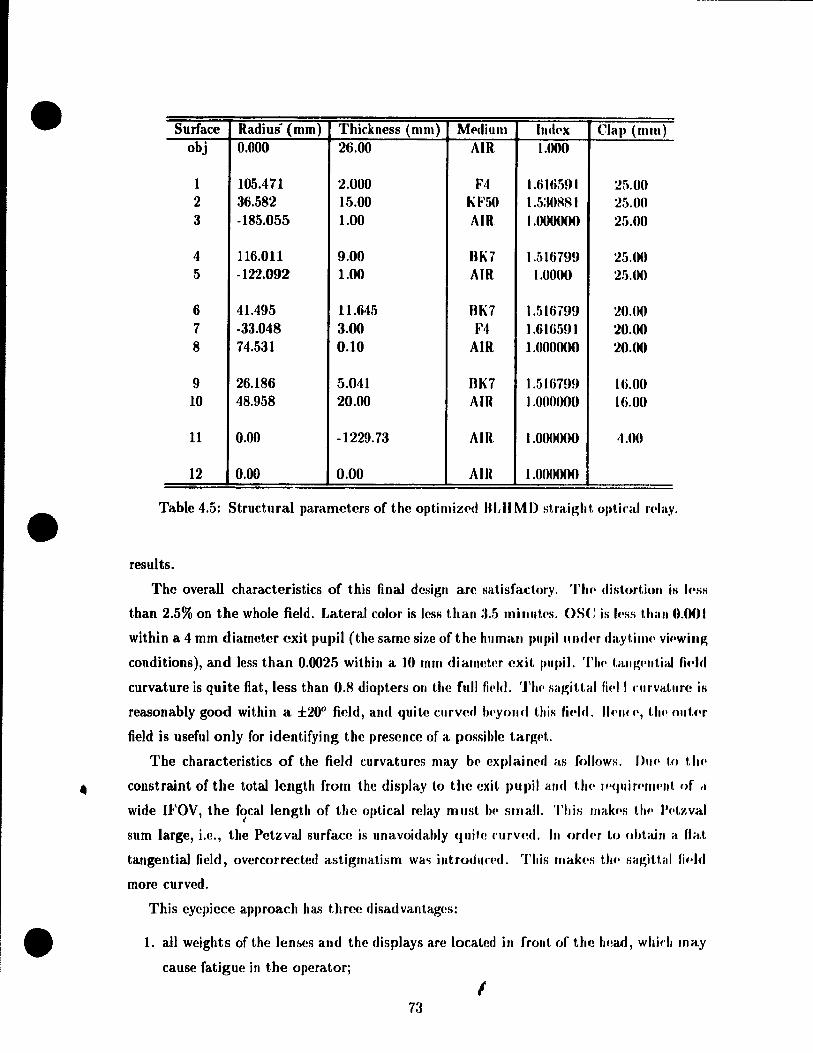
•
•
•
Surface Radius' (mm) Thickness (mm) ME'diuOl Indt'x Clap (mm) obj 0.000 26.00 AIR 1.000
1 105.471 2.000 F4 1.6W591 25.0() 2 36.582 15.00 KF5() 1.530R81 25.()O 3 -185.055 1.00 AIR 1.000000 25.0()
4 116.011 9.00 BK7 1.51(;799 25.00 5 -122.092 1.00 AIR t.OOOO 25.00
6 41.495 Il.645 BK7 1.5167!)9 20.00 7 -33.048 3.00 F4 1.616591 20.00 8 74.531 0.10 AIR 1.000000 20.("'
9 26.186 5.041 BK7 t.SW799 W.()()
10 48.958 20.00 AIR 1 .O()()OOO W.OO
11 0.00 -1229.73 AIR 1 .ooonou 4.00
12 0.00 0.00 Ain J .O()()OOO
Table 4.5: Structural parameters of the optimizt'd "LII MD straigh t. o)'I,kal n,IllY .
results.
The overall characteristics of this final design are satisfactory. 'l'lu' distortion is I('ss
than 2.5% on the whole field. Lateral color is less titan :1.5 milllltl's. ose is I('ss t.han 0.(0)
within a 4 mm diameter exit pupil (the same size of the human pupillUul,'r da,yt.illH' vi.·wing
conditions), and less than 0.0025 within a 10 mm diameter exit pupil. 'l'lu' tallJ.!;f'lItial fif'ld
curvature is quite fiat, less than 0.8 diopters on the full fi('ld. 'l'Il(' sagiUal fipll l'lIrvatllre is
reasonably good within a ±20° fip-Id, and (luite curve.! lu'yoJl(I this fi .. ld. UNU ", t1 ... OIJt.N
field is useful only for identifying the presence of a possible t.arg('f..
The characteristics of the field curvatures may b(' explaill('(1 as follows. Du.' 1,0 tlu'
• constraint of the totallength from the display to the exit pupil lIIul tlH' 1f'<Juirf'IIH'1I1. of ,1
wide IFOV, the focal length of t.he optical relay must 1,.. smalt. This lIIak.'s tlu' Pf'l.zval , sum large, i.e., the Petzval surface is unavoidably (Iuih! rurved. In ordN to .. htain a fiat
tangential field, overcorrected astigmatism wa'i intro(ju('('d. This rnak('s t/ ... SilJ.!;it,l,id fi .. ld
more curved.
This eyepiece approach has three disadvantages:
1. aIl weights of the lem.es and the displays are locatf!d in frollt of th(! Iwad, whid. rnay
cause fatigue in the operatorj
1 73
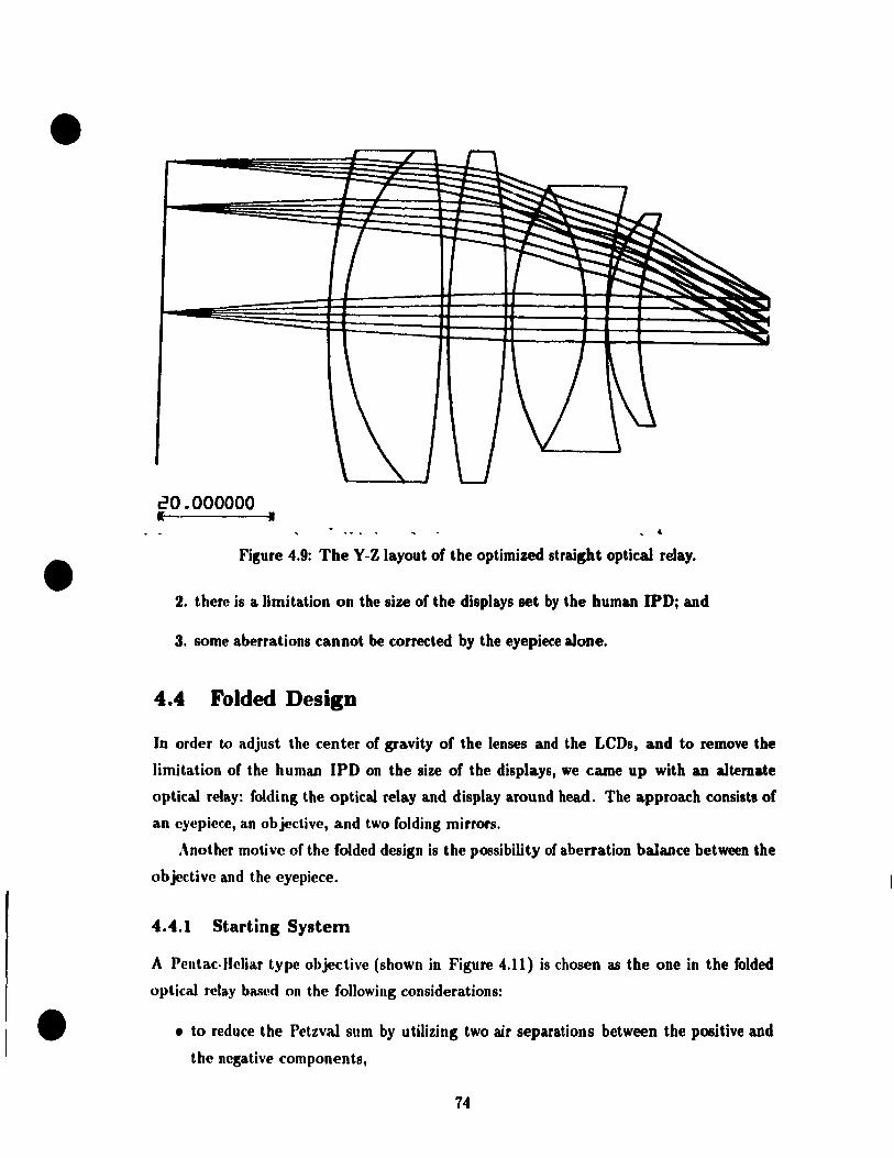
•
•
•
20.000000 1- •
Figure 4.9: The Y-Z layout of the optimized straight optical relay .
2. there is a Umitation on the size of the displays set by the human IPDj and
3. sorne aberrations cannot be corrected by the eyepiece alone.
4.4 Folded Design
In order to adjust the center of gravit y of the lenses and the LeDs, and to remove the
limitation of the human IPD on the size of the displays, we came up with an altemate
optical relay: folding the optital relay and display around head. The approach consista of
an cyepicce, an objective, and two folding mirrors .
• \nother motive of the folded design is the possibility of aberration balance between the
objective and the eyepiece.
4.4.1 Starting System
A Pentac-lleliar type objective (shown in Figure 4.11) is chosen as the one in the folded
optical relay based on the following considerations:
• to reduce the Petzval sum by utilizing two air separations between the positive and
the negative components,
14
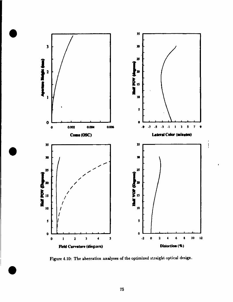
• J5
3 JO
1 Z5
1-12
115
1. 1 10
5
0 0
0 0.002 O • ..,. 0.006 -, ·7 ·5 -3 ·1 1 3 5 7 , C ... (OSC) LIlier •• Color (.i .... )
35 35
• 30 \
" " 2S " Z5
1» /'
1-/ /
/ /
115 / t 15 /
1 1 1 10 1 10
1 5 1 5
1-
0 0
0 2 3 4 5 ·2 " 2 4 6 • 10 12
Field Clln.'.re (diopœn) DistortÏOll (.,.)
Figure 4.10: The aberration analyses of the optimized straight optical design .
• 75
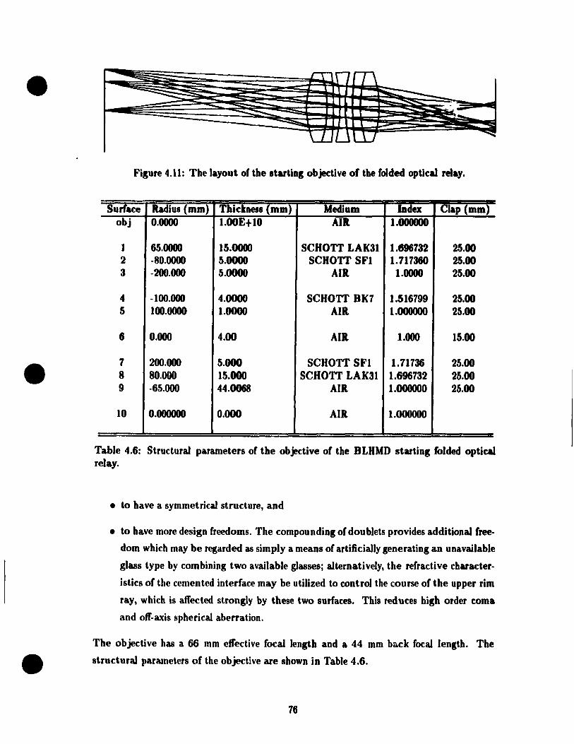
•
•
Fisure 4.11: The layout of the startins objective of the folded optical relay.
Surface Radius (mm) Thi~kness (mm) Medium ~dex Clap (mm) obj 0.0000 I.00E+I0 AIR 1.000000
J 65.0000 15.0000 SCHOTT LAK31 1.696732 25.00 2 -80.0000 5.0000 SCHOTT SFI 1.717360 25.00 3 -200.000 5.0000 AIR 1.0000 25.00
4 -100.000 4.0000 SCHOTT BK7 1.516799 25.00 5 100.0000 1.0000 AIR 1.000000 25.00
6 0.000 4.00 AIR 1.000 15.00
7 200.000 5.000 SCHOTT SFI 1.71736 25.00 8 80.000 15.000 SCHOTT LAK31 1.696732 25.00 9 -65.000 44.0068 AIR. 1.000000 25.00
10 0.000000 0.000 AIR. 1.000000
Table 4.6: Structural parameters of the objective of the BLHMD starting folded optical relay.
• to have a symmetrical structure, and
• to have more design freedoms. The compounding of doublets provides additional free
dom which may be regarded as sim ply a means of artificially generating an unavailable
glass type by combining two available glassesj alternatively, the refractive charuter
istics of the cemented interface may be utilized to control the course of the upper rim
ray, which is affected strongly by these two surfaces. This reduces high order coma
and off-axis spherical aberration.
The objective has a 66 mm effective focal length and a 44 mm back focal length. The
• structural parameters of the objective are shown in Table 4.6.
76

•
•
•
30.000000 • 1
Figure 4.12: The starting system layout of the folded optical relay design.
We choose the optimized straight design as the eyepiece in this folded starting system.
One field lens was added in front of the eyepiece in order to coUed marginal rays. The
system layout is iUustrated in Figure 4.12.
4.4.2 Design Procedure
An objective and an eyepiece are aU positive lenses, but they differ in that the entrance
and exit pupi1s of an eyepiece are outside the eyepiece, and usually the objective has a
longer focallength and an aperture whose position can be adjusted as a design frecdom .
Consisting of an eyepiece and an objective, the folded BLHMD optical relay has an exit
77
•
•
•
pUJ)il out!iid,! the systf'm (same with an eyepiece) and an intermediate image formed by the
objectiVf~.
The sy,.,tmn abf!rrations may be corrected by the objective and/or by the eyepiece. One
da,;" of aberrations have to be corrected by objective and eyepiece independently, such as
tfw I)etzval curvature and laleraI color; the other aberrations can be compensated between
tfH! objeftive and the ('y(!piecc, such as coma, astigmatism, and distortion. The Petzval sum
of the objf!('tive and the eyepiece must be kept as low as possible.
The Objective
The first step is to optimize the objective by evaluation of the intermediate image. The
sam(! tyP('s of aberrations are included in the merit function, but more weight are put on
tl ... P(!tzval (:urvature and lateral color.
The optimized objective is inserted iuto the folded system with the well-corrected eye-
piN'(' .
The Whole System
Th(' u('xt st('p is t.o optimize the whoJe system. The method to calculate and form the merit
funrt.ion is Ut(' same as the straight design.
Sine(! the system has more variables than the straight design, it took a longer time to
find ft minimum. 'l'he structural paramef,ers of the best solution we found is summarized in
Tabl(' 4.7.
4.4.3 Design Results and Analysis
This folded d('sign was optimized for a full unvignetted 8 mm exit pupil, a 20 mm eyerelief,
a.lld a. lit.tle );lfg('r than 60° JFOV. The lens diameters are allless than or equal to 25 cm.
'l'h(' layout of this system is iIIustrated in Figure 4.13.
TI\(' alwrratiolls of the final foldeù optical relay are analyzed in Figure 4.14. The lateral
('0101' on tll(' full fi('ld is I('ss than 2.5 minutes, which is smaller than the straight optical
r<'lay. This is adli(-'ved hy double corrections of the objective and the eyepiece. The coma,
pvalui\ted within a ,. 111111 diameter exit pupil, has the same value as that of the straight
syst('lIl. Th(' dist.ort.ion is a lit.tl(' worse and has a maximum of 4.7% at the margill field.
TIl(' fi('ld fil rvat.u r('t. art' worse. A part of the tangential field is beyond infinity, which is
ha.rd to <U'('OIIIIIlO(late for 1l10st people. The astigmatism is smaller .
Th(, ov('rall ('harartt'fistics of the system are Ilot as good as expected. It is understand
ahl(' t,hat t.!1(' folded system has a worse field curvature, because the objective and the
78

.. ----------------------------
•
•
30.000000 1( JI
Figure 4.13: The layout of the optimized folded opticaJ reJa.y .
• 19
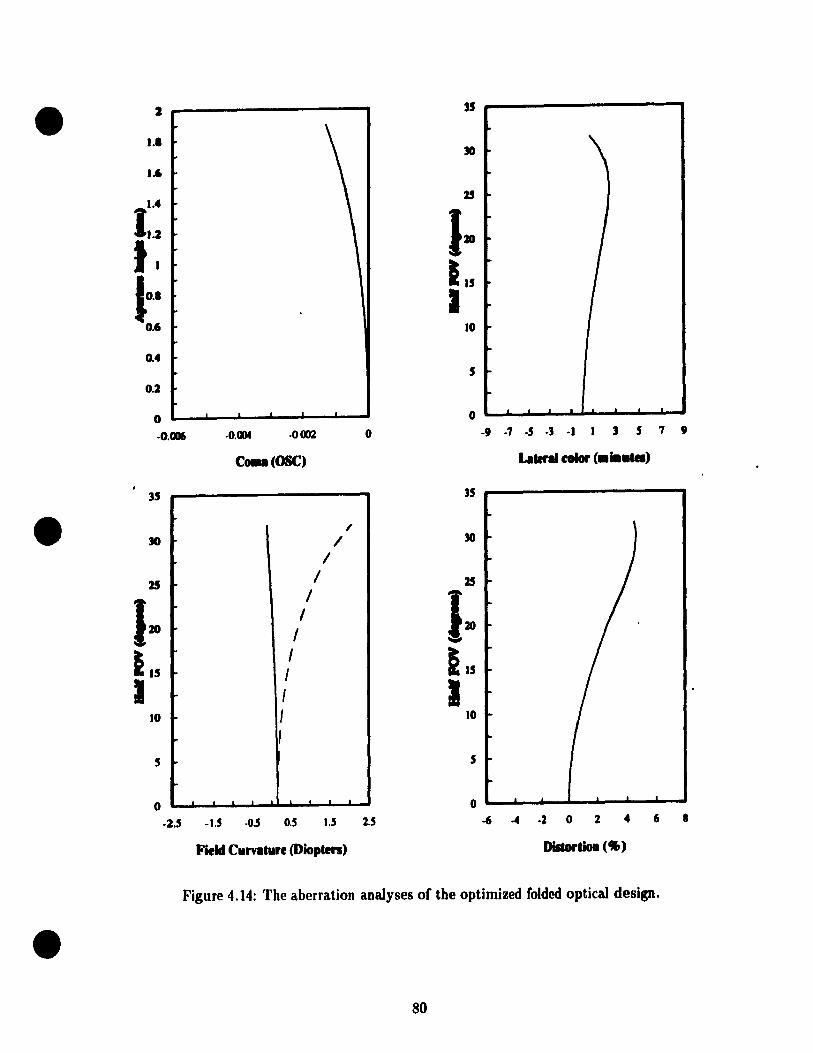
• 2 35
1.1
1.6
.... 25
11.2 1· 'I 115 1-
lU 1 0.6 10
1-0.4
5
0.2
0 0 .
-o.a ·0.004 .0002 0 -9 ·7 ·5 ·3 ·1 1 3 5 7 9
C .. (OSC) Late .... coIor ( ..... )
35 35
• /
/ 1
25 1 25
1· 1 1. 1
1 - -115
1 115 1
1 1 1 10 1 10
1 5
0 . • 0
·2.5 -1.5 ·005 0.5 1.5 :2.5 -6 -4 ·2 0 2 4 6 • Field Curvl'ure (Diopten) Disaortioa ('JI,)
Figure 4.14: The aberration analyses of the optimized folded optical design.
• 80

•
•
•
eyepiece are positive lenses and contributc tht' samc sign of fi('ld ('urvatllr(' 10 Ih(' sysl.'m.
The only thing we can do for this aberration is to kc('p t,)w Petzva.I Sil III for bnt.h of 1 h('1II
as low as possible. Coma and distortion were exp<,ctt1d to 1)(' sllIall('r. hlll il is ilOt. !.II(' ('ml('.
The reasons might be:
1. the whole system is no' ;ymmetrical about the interll1(ldiat(' iJna~(', and
2, the system is too complex, and the best solution we found is jus!. Cl lm'al minimulII.
The center of the folded optical relay and tht> LeDs can 1)(' adj,,!>!.c'd hy ad.ill!>t.ill~ tilt'
positions of two mirrors. The orientations of the Illirrors llélVt' t.o 1)(' kt'pt. tilt' I>lUll(', 'l'II<'
size of the LCD screen can be larger. Ali those are achiev('d at tht' l'Ost. nf mor!' c'omph'x
structure, more weight, and higher cost.
4.5 Summary
In Chapter 3, we derived the desired characteristirs of th .. BLIIMD opt.Ï<'al l'play. 'l'lu'
present chapter has presented the structural paranwt('rs of two difr~'I'('nl opl ical 1'(·I,IYs III
meet the desired characteristics, Olle optical l'play has a !>tl'ai~ht. forlll, and t.11(· ot.hl'I' ha!> a
folded layout.
The biggest problem in either the stl'aight 01' ttl<' fol<l('<1 optirall'('la.y (\(. 1f!.11 i:-. t.11f' I"OlIflirl,
among the requirement of the wide IFOV, the Iimit on the size of I('n!>('s, a.lld tlu' alH'rral,iulI
tolerances of the human eye. The other condit.ions whÎfh WJl1plic at.(' UH' (!<'sip;1I t.a .... k 'HI' ( 1 )
a relatively large eye relief and (2) a large exit pupil.
The straight optical relay is a complete eyepiece cOflsi~t.illg of J(I 1>1I1'I'ar(·:-,. 'l'hl' rl1;.r
aderistics of this optical relay are satisfactory afl,t'r ils opt.imizat.ioll. Th i~ upl.Îral Il'lay is
relative simple compared to the folded (!esign. The major drawh,\f'ks aI'l' t.hat. t.hl' ('1'111,('1' uf
gravit y of the relays and LeD screens is ill front of t.h(' op(~rat.()r's lu·ad, and tllC'I(' il> a,IÎlllit
on the size of LCDs due to the human operator'!> IPD.
The folded optical relay locates the Lens on th(' two :,idC's of thp IU';I(I, IU'II( (' allow:, 1.111'
use oflarger size tCDs. The other advantage if, that t.he ('('II IN of I!;IlLvity of UIP opl.i( al l'pl,l,y
and LCDs can be adjusted. Although the efred of alH~rration halall«' IH·I,WC'C'II t.11f' o/'j.·' t.iVf'
and the eyepiece is not as obviolls as wc exp(~('t(ld, Ut(' al)(lrral.ioll!, ail' ,III 1-./IIallf·1 I.hall I.h,'
design criteria except the field curvature. This is dlH' t.o thf' f,1( 1. t./lat. HII' oh j(·ct.ivf' .lIul 1./".
eyepiece are ail positive, and the field curvature introdll( ('cl hy 1 IH' ohjf'C'l.iVl' ih ,·nll..,u ('d hy
the eyepiece, in lieu of being compensated. The fol<l('cJ optkal l'play ha~ mOll' Jf'II1-.('~, hPfU'('
has more weight than the straight optical l'play. If more time b takPII 011 f,PiI 1{ hlllV; fol' an
alternative folded structure, i.e., choosing difft'fcnt f.tarting strllct.lITf·~ fOI 0,,· ob jf'( t.iv,· and
8]

•
•
•
LIli' ('yepi('('I', and on the optimization, the folded form optical relay may hold the promise
of beHer aherration correction.
Toleraru'PFi on the lens J1aramet.ers of each optical relay, which are not discussed in this
thf!fois, should be calculated before a prototype is made. Although practical tolerances May
tif' f'xpe('l,pd to b(' foignificantly larger than the (:alculated tolerances [8], the calculated ones
provid(! guidelin<!f> for sel tillg practical tol('rances .
82

/
• r
Surface Radius (mm) Thickness (Ill Ill) MediulII h"l('x Clap (III 11\ )
obj 0.000000 120.000000 AIn 1 .nooooo
1 0.000000 0.000000 RBFI, l.nOO()OO :1O.()O()()()()
2 0.000000 -20.000000 AIn 1 OO()()OO
3 -41.761055 -18.000000 SCIIOTT LAI\2:J 1.()f)~R Ir, ~.r;.()()O()O()
4 71.473247 -4.000000 SCIIOTT SFI 1.717:JfiO 'lf •. O()OI}I}O
5 352.219345 -0.500000 Am I.OOtlOOO 'l!l. 0000 00
6 -132.056300 -8.000000 SCIIOTT HK7 I.!ll fi ïH9 2·l.OOOOOI}
7 -30.316313 -6.895022 AIH 1 .OOO()O() 22. ()OOOOO
8 -50.415401 -7.061731 sellOT'!' SFI 1.717:Jf;O 2 !;,(J()()O (lO
9 -690.751553 -1·1.000000 SCIIOTT LAICJ1 1.(i!}(iï:J·l 2!). ()()()O(}O
10 -817.205693 -40.000000 Am 1 .OOO()(}() 2fl.OOOOOO
11 0.000000 0.000000 HEFI, 1 .OOOO()(} :m.O()OO()O
12 0.000000 23.035298 AIH 1.000000 13 0.000000 14.122293 AIH 1 .OOO()OO 2rdJOOOOn
• 14 94.137016 7.209360 SCIlOT'!' SFR 1 JiHH!):J 1 n 000000
15 -543.642373 0.100000 AIH 1 .OOO()O(} 27.()()OOOO
16 -217.45.5927 3.000000 SCIIOTT F4 1 (j 1 fi5!) 1 27.000non
17 34.747895 15.000000 sellO'!'T KF!)O 1 5:JOHH 1 2,1.000000
18 -62. 106M 1 1.000000 AIH 1 .OO()()OO 2" . O()OOOO
19 79.377106 10.000000 SCIIO'!'T BK7 1}')J(mm 2,1. nOOOO()
20 -115.108893 1.000000 AIH 1 .nou(}o(} 2/1.0()Onno
21 34.040843 12.000000 SCIIOT'!' BK7 I.!) J(j 7!)!) 2 1 .oonooo
22 -45.208412 3.000000 SCIIOT'!' 10'1 1.(; J(j;)! Il 2 1 OOO()OO
23 54.916834 0.100000 AIH 1.000000 2().(}OO(){)O
24 24.334637 .5.060000 sellOT'\' BK7 1.1,1 (i7!)!} 1 f;,()(}OOOO
25 38.665779 20.000000 AIH 1 .0 OOO()O 1 fi. OOOOOU
26 0.00000 -11;;n.52n7:J AIR 1 O()OO 1\ O()OOOO
27 0.000000 0.000000 AIR 1 000000 fiO.OOOOOO
Table 4.7: Structural pararnctcrs oft" .. optirnlzpd BLHM/) fold('d optir"J 'Play
• 83
•
•
•
Chapter 5
Conclusions
5.1 Summary
The objectives of this thesis were:
1. to derive optical design criteria with the consid('ratiolls of Hw huma.1I fal'I,ors alld
optical constraintsj and
2. to design an optical rday for use in the 8UIMD system. 'l'lu' optical syst'('J11 ha.s
an IFOV greater than 60° and well-corr('cted aberrations, alld satisfi('s hlllllail f .. dor
constraints.
This thesis reviewed the alternate approaches to three Il MD cOnl,)(lnl'lIt.s: elihl.lay:-. ur
image sources, optical relays, and cornbiners. The optical f('lay is tlJ(' k,'y (·ollll'0n('lI1. if il
wide IFOV is required. We obtained two different relay lens sySt.('fIl~, a ht.raiJ!;ht. form ,11111
a folded form. Each of them has an IFOV greater than (iW'. 'l'lu' d('si~1I pro(,f·,I"ff·S ,wei
aberration analyses were also presented.
HMDs have been designed as a possihle rneans of lIIan-rnal'hillf' int.l'rftu·{·. Tooht.ain
the design criteria, we reviewed and discussed the major fa(·tors aff"ct.ing UI(' 1.lIl11an vh;ual
acuity, the human visual requirements, optical limitations, and the part.irular itl'l'lkation
of the BLHMD. The optical design criteria we obt .... in('d indud(' human fad.or fonst.raints,
aberration tolerances, and other constraints.
A brief review of first order opties, aberration theory, genNal dm,ign priJl(·il.h!s, and
computer aided lens design was given .
84

•
•
•
5.1.1 BLHMD System
U;t/wd on tlll' rcvi('wf> of the alt,(lrnatc approaches to the HMD components and the discus
hinnf> ahout thp JI M 1)'1> application conditions for telerobotics, we decided on an approach
tu 01(' ('olrlpunl'J1ts in thp BLIIMD system. Our BLHMD will have the following features:
• Color LeUs,
• Sten'o vision.
• Widp WOV: larger than 600, and
• COulI,utcr combiner.
5.1.2 Design Criteria and Design Characteristics
Tahl(! 5.1 summari1.l·s the del>ign crit('fia and the characteristics of the two optical relay,
in Will parisofl with the dl'sign targ('ts. The straight optical relay consists of two doublets,
Parameters Design Target Straight Design Fo lded Design WOV > 60° 62° 61° L('ns diallJ('ter (Ulm) < 55 < 54 < 54 1'~y(·r .. 1 ief (Ill nt ) > 18 N 20 20 20 l'~xit pupil (mm) 10 10 8 Distortion (%) < 5 NID < 2.5 < 4.5 Lateral ('(Ilor (min) < 5 NID < 3.5 < 2.5 Coma (OSe) < 0.0025 < 0.001 < 0.0015 'l'Fe (diol,t('r) < 0.9 < 0.8 < 0.7, part of field
is b eyond 00
SFC (<lio.) < 3 < 3 within ±20° FOV < 2.5 AstigmatislIl (li io.) < 2 < 2 within ±20° FOV < 2 W(·ight. as Iight as possible Hght hea vy Shapl' of 1('lIs spherical spherical sph erical
'l'abl(' 5.1: SlIllImary of t.hl' design criteriet and the characteristics of the two optical relays. 'l'Fe is Ul(' tangellt.ial field curvat.ure. SFC is the sagittal field curvature.
Ol\(' hkollvl'x I('ns, and one Il1l'lIiscus lens. Its characteristics are satisfactory. But the
sagitta,) fil·ld is quitl' rurved in t.he field beyond ±20°. Bence the outer field is useful
ollly for id(·IIt.ifying the pr('sellr(' of a possible target. The folded system consists of an
obj(·rt.iv(', élU cy('pil'c(>, and two mirrors. Decanse of the complexity of the system, this
syst,t'l11 WilS 01,t.imizl'd wit.hin a 8 mll1 exit pupil, which is smaller than the desired 10 mm.
85
•
•
•
Ali the aberrations are smaJler titan the design criteria ex('ept that a part of tan~('ntial fi('ld
curvature ;s beyond infinity.
Compared to the straight oiltical rela.y, t.he fold('d s.vstelll ran adJlIst. t tH.' ('('lItl'r of ~I'a\'ity
of the &ystem and the LeD, alIows th(l USl' of larg('r displays. Hut tlu' fold('(1 n'Iay is mort'
Coml)lex, more heavy and mor(l (lXI)e'lsiv(l to 1)(' madl'.
5.2 Limitations and Recommendations for Future Research
5.2.1 Structure of Optical Relays
For reasons 01 manufacture and cost, only splH'rical I('oses wer(' 111,(,11 in ollr "ptkal d('sigll.
In order to control aberrations under ollr desired levels, 1.0 havl' a will(' IFOV, alltl 1.0 k("'"
diameters of lenses smaller than 25 cm, both straight. and foldl'd opt.i(·al 1('lays ('lIIplnYNI
complex structures: the straight relay has 10 surfa('('s alld tll(' foldpd r('I".v Itas 2t surfa('('s.
To simplify the structures or to reduce t.he nllllll)('r of surfa('('h, th('n' an' t.hJ'(·(' IIwt.hmlh:
• use of asphericallen<;es,
• use of gradient index lenses, and
• computer aberration compensations.
5.2.2 Aberrations
There are several alternate approaches to the aherration corrections.
Opticlll Fiber Field Flattening Lens
A wide IFOV and the constraint. of totallength of relay re(luir(' a short. fO('all('lIgth; a short.
focallength usually means a large Petzval sumo '1'0 flattf!ll th(! fj('ld-of-vif'w, (Jwr-('om'( "NI
astigmatism has to be introduced. But too much of titis will hadly hlllr t.l1(' Ollt.f'f illlagf'.
Another way to achieve a fiat field is by employing an oJ>tkal liher fi('ld fla.t.t.l'lIillg If'lIs. On(!
example is to insert this lens between the objective and the ('Y('J>im'(' of t.hf' ÎoldNI f(·lay, alld
let the two surfaces of the optical liber lens have the sam(' mfvat.ure with imag{' phul('/; of
the objective and the cyepip.ce, which are ail mnl'ave (Figure 5.1).
Symmetric Structure
The aberration analyses of the folded optical rclay showed that th(· aherration r.orr(J(:tiort
was not as good as we expected. One important rcason is that the whole sysl.em (i,)(:luding
86
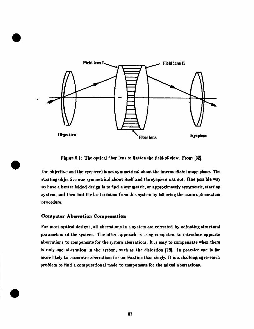
•
•
•
Field lens Il
Objective Eyepiec:e
Figure 5.1: The opUcal liber lens to flatten the field·of·view. From [32] .
the objective and the eyepiece) is not symmetrical about the intermediate image plane. The
starting objective wu symmetrical about itself and the eyepiece wu not. One possible way
to have a better folded design is to lind a symmetric, or approximately symmetrie, starting
system, and then find the best solution from this system by foUowing the same optimization
procedure.
Computer Aberr.tion Compensation
For most optical designs, aU aberrations in a system are corrected by adjusting structural
parameters of the system. The other approach is using computers to introduce opposite
aberrations to compensate for the syst~m aberrations. It is easy to compensate when there
is only one aberration in the system, such as the distortion [251. In practice one is far
more Jjkely to encounter aberrations in combination than singly. It is a chaUenging researeh
problem to find a computational mode to compensate for the mixed aberrations .
87
•
•
•
Bibliography
[1] Military standardization handbook: Optical dt'sign (mil-hdhk- HI). (A rllly ('ollt.rad
No. DA-36-038-0RD-020690) Departrn(,lIt of J)ef('lIse, Washingt,oll ne, USA, J!)()~.
[2] K. E. Baker. Sorne variables inflllencing vl'rni<'f (l(,lIit.y . .1. (J1Jlu'fll SOI'/dy of AIIUTÙ'(/,
39(7):567-576, 1949.
[3] K. Boff and J. Lllleoln. Eng"wering Daia (.'omIJf'rulium: Ib/1/um l)f"'("'I'/f(J1I mlfl [>C"
Jormance. AAMRL, Wright-Pattersofl AFB, Ohio, J!)RX.
[4] J. Bridenbaugh, W. Kama, and L. Task, Il. 'l'II(' h('lflH't-lIIollnt('d hlld: il. ('hangf' ill
design and applications approach for helrn('t.-mollllt(,d di:-.plays. III AGA un (,'mlf,T,'''('('
Proceeding No 329, pages 30-1 -:10-5, 1')82.
[5] J. Brown. The structure of the visual ~yst<'IIl. In C. Graham, ('ditor, l'1."Ium fII/f1 l'l.'mftl
Perception, pages 39-59. Wiley, New York,U .S.A., 1966.
[6] G. Burton and N. Haig. Effe('ts of the Seidel aberrations on visual j,arg('t, disnilllillat.ioll.
J. Optical Society of Amerzœ, 1:373-385, 1981.
[7] F. Campbell and D. Green. MOllofular versus hinoclliar visllal a(,lIity. Na/un', :lOlo!: I!H
192, 1965.
[8] A. Damon, H. Blt:ibtreu, O. Elliot, and G. ~. Predi<:ting sOlllatot,)'f)(' fJOm hody Ulf'a,
surements. American Journal of Physlcal AnthmlKJmr:tr!l, 20:tI()J tl7:l, I!}():l.
[9] G. De Vos and G. Brandt. Use of holographie opt,iml ('lf'IIu'lIb ill hll"II,. III
R. Lewandowski, editor, lIelmel-Mounted IJisplflY (Ji), pag('s 2-~, OrJ;uulo, Florirlil,
April 1990. SPIE- the International Sodety for Optical En~irH!('fjflg.
[10] J. G. Droessler and D. Rotier. Tilted cat h('lrnct-mountcd disJ)lay. OTJtif:(ll/~'Jtflirl(;('riflfJ,
29(8):849-854, 1990 .
[11] H. Erfte. U.S. Patent 1,478,704 filed on August 1921.
88

•
•
•
[I:l] n. Farrcl1 and .1. Booth. D(~8ifln lIandbook for Imagery Interpretation Equipment.
Bo('ing AN()~paCe Co., Sf'attle, WA, 1984.
[J:J] M. Griot. (J!Jii,...; (lUIfJ .5, chapter One. Melles Griot Inc., Irvine, CA, USA, 1991.
[141 .1. IIpard, D. lIay('f" .1. FNrPf, and A. Zilgalvis. Design of an airborne helmet-mounted
di~play. T'('chnif al report, 111Ig('s Aircraft Co. under contract to US Aerospace Medical
Hf'~paf('h Lahoratory, l!J6!). AMUL-TR-74-3.
1 )!i] Il. IIf'rt~herg, G. f)aTli('I~, and E. Churchill. Anthropometry of ftying personnel-1950.
T('('hnifal r('I)()rt, Wright Air Development Center, 19054. WADC-TR-52-321.
[Hi] W. Ki"" A. Liu, K. MatslInaga, and L. Stark. A helmet mounted display for teter
ohotirs. Il'J'I~'I~f J. liolHJfic.'I (m(l Automation, pages .143 - .547, 1988.
[171 IL Kingslak('. Lots /)esiyrt FtwlJmnenfals. Academie Press, New York, USA, 1978.
II~] n. Kingslak('. Lens D('.~ig1t Flindamcnfals, chapter 15. Academie Press, New York,
USA, 1978.
[WJ M. Millodot, C .. Johnson, A. Lamont, and H. Leibowitz. Effect of dioptries on peripheral
vislIal iU:lIit.y. Vision Research, 15:1357-1362, 1975.
[20J Optikos. A CC08 V Manual, 1990.
[21J E. Pd. Visnal issues in the use of a head-mounted monocular display. Optical Engineer,
:.m:~s:J R92, 1990.
[22J U. A. P<,rl'z. neclrollic DislJ/oy Del,ices. TAB Professional and Reference Books, P.O.
BOx 40, Bh1(' UicJgc SlIrnmit, PA, USA, 1988.
[2:JJ P. U('('v('s. The rate of pupil1ary dilation and contraction. Psychological Review, 25:330-
:1/10, 1918.
[:>'.IJ A. U('irhert. and B. (;oh('lI. Prismatic combiner for head-up display. In II. Assenheim,
~ditor, mSI,/ay System OIJtics( Il), pages 197-202, Orlando, Florida, March 1989. SPIE
. t.h(' Intt'ruational Society for Optiral Engineering.
[2[IJ W. Uohill('U and J. Rolland. A computationaJ model for the stereoscopie opties of a
Iwad-mount('d display. l',.cscure, 1:45-62, 1992 .
[26J P. nogers. Visual opt.Î<'al syst<'fllS. Mat.eriaJ for Lens Design Summer Course, University
of 1l0rlwstN, .11llH' 1991.
89
•
•
•
f27J S. Rosin. Eyepieces and Magnifirr$, VOIU11H' Ill, C'hapt<'r 9. pagl's :1:1 t :UiI. At'"d('lIIk
Press, New York, U.S.A., 1965.
[2RJ S. Shla<>r. The r<,lation betw('e11 visu al acuity a.nd iIIuminat.ion .J0ItI'I1lI1 of (,'fllfrYIl
Physiology, 21:165-188, 1937.
[29] W. Smith. Modern Opliral Engineering. 0l,tical and J'~I('dro-Optiral EII~illl'Nill~
Series. McGraw-llill, In ... , New York, l1SA, M'rond editinn, H)!)().
[30] E. Tayler. The inverting eyepiece and its <,volution . ./. 8ri. /1I8f,'., 1:'bt:' ·tH, U).I!).
[31] M. Thomas, W. Siegmund, and S. E. Antos. Filwr opl k dl·wloPIlll'IIt. for IIS{' 011 t.l1(·
fiber optic helmet-mounted display. O'Jtiral Enginef"'iuf/, 2H( ~):R!):) ~(i2, !Hm •.
[32] Z. Wang. Geornetrical O/JUcal and O/Jtiral f)('.~ifln. ZIH'jiang {lnivNsit.y Pr('ss, Zh('jiang,
P.R. China, 1989.
[33] Z. Wang. Geometrical Optzcal and O,JtiCllI Design, ('hal)tN 15. ZIH'jiallg lJ lIivl'l'sit.y
Press, Zhejiang, P.R. China, 1989.
[34] M. Weinstock, W. Pishtey,.J. LaRussa, and C. Tritsrh. A holop;raphif' 1\('11II('t. lIIoullt.pd
display application for the extravehicular mohilit,y unit. III IL L(\wandowski, l'c1it.or,
Helmet-Mounted Display (II), pages 2-8, Orlando, Florida, Al,ril WHO. SPI E- Uu' In
ternational Society for Optical Engineering.
[35J M. J. Wells and M. Venturino. Performallc(' a.JllI head movellH'lIt.s IIsing a. 11t'11I)(·t
mounted display with different sized ficld-of-view. O/JtiCfll Rn!/;,u'("'IrIf}, 2!):H70 H77,
1990.
[36] G. Wilson and R. McFariane. The developmf'lIt of an aviators hdm~t IJIOUIlt,(·(j night.
vision goggle system. In R. Lewandowski, cditor, 1Ie1"u:t-Mmmt(:(llJz.~TJlflU (II), pag('f,
128-139, Orlando, Florida, April 1990. SPŒ- the [lItNnational SofÏ('ty for 0l,tkal
Engineering .
90