optical engineering 2.5 optical mouse universität ... · • instrument combines collimator and...
TRANSCRIPT

Universität Karlsruhe (TH)
Optical Engineering
Martina Gerken06.12.2007
6.2
Course outline1. Imaging optics2. Optical sensors
2.1 Spectroscopy2.2 Material characterization2.3 Distance measurement2.4 Angle measurement2.5 Optical mouse
3. Optics in data storage4. Introduction to displays -> Presentation by BARCO (end of semester)5. Fourier optics (starts 13.12.2007)6. Diffractive optics and holograms7. Integrated optics8. Computerized imaging
6.3
Interferometric distance measurement• Interferometer
– Light split into at least two beams – Beams propagate different optical paths– Superposition of beams at exit
• Interference effect occur for coherent superposition– Interference pattern depends on optical path difference that beams incur
before superposition.• Precision measurement possible by evaluation of optical interference pattern• Examples for interferometers
Fabry-Perot Michelson Mach-Zehnder
Source: Naumann/Schröder, Bauelemente der Optik, 1992
6.4
Newton‘s rings• Newton‘s rings due to interference of light reflected on lens and light reflected
on glass plate
Source: wwwex.physik.uni-ulm.deWithout lens error With lens error

6.5
White light interferometer• Interference of broad band light source (white light) used
– White light has small coherence– Interference phenomena only visible if optical length of both paths in
interferometer identical within coherence length (~λ) – Object scanned in z-direction by movement relative to reference plane
• „Depth image“ of object with small measurement uncertainty generated– Setup needs to be very stable
Source: www.3d-shape.com
6.6
Time of flight distance measurement• Emit laser pulse and determine time difference until detection of reflected
pulse• Calculation of distance using propagation velocity
• Problem: Light is fast– Propagation time for distance of 1 m is 3 ns
• Short laser pulses and fast electronics necessary
6.7
LIDAR (Light Detection and Ranging)• Compare to Radar:
– Electromagnetic wave emitted and reflected signal analyzed
Source: http:// www.dlr.de/schoollab/
6.8
LIDAR applications• Coordinate measurement using time of flight
• Dynamics of gas turbulences by time of flight measurement and Doppler shift
• Chemical analysis (Pollutant concentration in atmosphere) by time of flight measurement and spectral measurement (Raman signal)
DEM: Digital elevation model

6.9
Raman scattering• Raman signal provides fingerprint of molecules as vibrational states specific
for chemical bonds– Fingerprint region of organic molecules typically 500-2000 cm-1
• In solid state physics Raman signal used to, e.g., characterize materials and measure temperature
• Difficulty is to separate weak Raman signal from background
Source: en.wikipedia.org
6.10
LIDAR-System (Example Univ. Baltimore)
Pentium 133 MHz laptopData acquisition
1.5mMaximum range resolution
Azimuth rotary stage (180:1), stepper motors & encoders, elevation right angle reducer (100:1), i.e. from 90o to -10o, AT6400 controller (Compumotor)
Scanning system
12-bit 100MHz, dual channel (Signatec PDA 12)Digitizer
IR-enhanced Si avalanche photodiode (Analog Modules)Detector
25.4 cm (10 in) diameter, Cassegrain f/10, 5mrad FOV (Meade LX50)Telescope
Q-switched Nd-YAG with 320mJ at 1064nm (additional wavelengths: 532nm and 355nm); 30Hz repetition rate; 8ns pulse; 1.8 mrad beam divergence; BigSky laser model CFR 400
Laser
6.11
Distance measurement by contrast evaluation• Modification of objective position until image focused• Reading of distance on objective scale• Called contrast measurement as image contrast maximum in focus• Auto-focus of digital camera works using contrast evaluation
– Processor of camera calculates spatial frequency distribution of image– Image closer to focus if fraction of high frequencies larger– Multiple images with different focusing necessary to evaluate contrast– Alternatively, beam splitting may be used
Source: Naumann/Schröder, Bauelemente der Optik, 1992
6.12
Source: Naumann/Schröder, Bauelemente der Optik, 1992
Auto-focus using astigmatic imaging• Illumination spot A imaged via objective and cylindrical lens astigmatically
onto quadrant diode• For correct focusing signals on x-diode and y-diode identical• Setpoint tracing obtained from difference signal
– Used in CD- und DVD-players

6.13
Course outline1. Imaging optics2. Optical sensors
2.1 Spectroscopy2.2 Material characterization2.3 Distance measurement2.4 Angle measurement2.5 Optical mouse
3. Optics in data storage4. Introduction to displays -> Presentation by BARCO (end of semester)5. Fourier optics (starts 13.12.2007)6. Diffractive optics and holograms7. Integrated optics8. Computerized imaging
6.14
Angle measurement using collimator and telescope• Collimator: Projector that images illuminated reticle to infinity • Telescope with reticle used for evaluation• Sensitive measurement of direction differences• Setup insensitive vertical alignment (Parallel displacement)
Source: Schröder, Technische Optik, 1990
Collimator
Telescope
6.15
Autocollimator• Instrument combines collimator and telescope
– Collimator reticle and telescope reticle both placed at focal plane of autocollimator objective
Source: www.moeller-wedel-optical.com
6.16
Example: Determination of track way profile• Measurement of angle while slide moves
Source: Schröder, Technische Optik, 1990
Result
Evaluation

6.17
Alignment telescope• Precision instruments for the alignment of objects to a reference line, which is
defined by the line of sight of the system
Source: Schröder, Technische Optik, 1990
• Alignment telescope focuses target to determine lateral displacement with regard to reference line– Setup insensitive against
rotation
6.18
Example: Evaluation of alignment
Source: www.moeller-wedel-optical.com
Source: Schröder, Technische Optik, 1990
6.19
Adjustment of telescope axis• Before use telescope axis
needs to be aligned with track way– Adjust height to front
target– Adjust direction to
rear target– Repeat if necessary
• Identical procedure for adjustment of alignment laser with two iris apertures
Source: Schröder, Technische Optik, 1990
6.20
Course outline1. Imaging optics2. Optical sensors
2.1 Spectroscopy2.2 Material characterization2.3 Distance measurement2.4 Angle measurement2.5 Optical mouse
3. Optics in data storage4. Introduction to displays -> Presentation by BARCO (end of semester)5. Fourier optics (starts 13.12.2007)6. Diffractive optics and holograms7. Integrated optics8. Computerized imaging

6.21
Opto-mechanical mouse (since 1984)• Direction obtained from time sequence of signals
6.22
Optical mouse (old – since 1968)• Special pattern on mouse pad used for modulated reflection during movement
6.23
Optical mouse (new)• Image scanned (as in digital camera) and displacement calculated
Source: http://www.logitech.com/lang/pdf/laser_techbrief-04.pdf
6.24
Examples for optical mouse systems• Different systems:
• Example of image from bottom
Source: http://www.howstuffworks.com
Source: http://www.mstarmetro.net/~rlowens/OpticalMouse/

6.25
Laser mouse (very new – since November 2004)• Illumination with IR-laser• Image taken with camera• Movement of speckle-pattern evaluated
Source: http://www.logitech.com/lang/pdf/laser_techbrief-04.pdf
6.26
What is speckle?• Speckle (laser light-granulation) occurs upon reflection or transmission of
coherent light on rough surfaces or distributed scatterers
6.27
Diffraction on grating
• Interference effect of large number N of scattering points k with fixed phase difference ϕk between 0..2π
• Each scattering point is origin of spherical wave. Waves superpose at observation point r
Observation point r
( )1
kiNk
k
a eA
N
ϕ
=
= ∑r
coherent light
λ
6.28
How does speckle form?
• Interference effect of large number N of scattering points k with random phase difference ϕk between 0..2π
• Each scattering point is origin of spherical wave. Waves superpose at observation point r
Observation point r
( )1
kiNk
k
a eA
N
ϕ
=
= ∑r
coherent light
λ

6.29
Speckle: influence of surface• Speckle occurs if roughness of surface larger than wavelength of light
Observation point r
coherent light
Roughness
λ
6.30
Speckle: influence of scattering particles• Speckle occurs in transmission if scattering particles are distributed in volume
with distance larger than wavelength of light• Possible difference to scattering on surface:
– Multiple scattering (random walk) increases effective roughness to more than layer thickness
Observation point r
coherent light
Roughness
6.31
Problems caused by speckle• Holograms
– Besides desired object and reference wave speckle exists due to rough objects
• Laser projection displays– Roughness of projection screen causes speckle and blurred images
• Astronomy– Wave front are disturbed in atmosphere and limit resolution (“Seeing”)
• Wireless microphone– Lecturer with wireless microphone cannot be heard at certain position in
auditorium (dead spots) • Ultrasonic imaging
– Granulated image due to speckle
6.32
Possibilities by using speckle• Speckle metrology
– Superposition of pattern 1 from measurement object and pattern 2 from reference object results in pattern 3 that depends on phase difference at given wavelength
– Surface analysis by comparison to reference surface

6.33
Laser mouse
Source: http://www.logitech.com/lang/pdf/laser_techbrief-04.pdf
6.34
Laser mouse (very new – since November 2004)• Other laser properties may be used as well
– e.g., Philips Twin-Eye laser sensor: Input device based on laser Doppler effect
Source: http://www.business-sites.philips.com/lasersensors/about/article-15031.html
6.35
Course outline1. Imaging optics2. Optical sensors3. Optics in data storage
6.1 Copier and laser printer6.2 CD-/DVD-player6.3 Magneto-optical discs (MO), MiniDisc (MD)
3. Introduction to displays -> Presentation by BARCO (end of semester)4. Fourier optics (starts 13.12.2007)5. Diffractive optics and holograms6. Integrated optics7. Computerized imaging
6.36
Early data storage systems• Data storage is used to save and distribute information independent of
humans
cuneiform writing
cave-painting
letterpress
music box

6.37
Photocopier• 1938: Effect discovered by Carlson• 1947: Technology licensed to Haloid• 1949: First commercial photocopier• 1961: Company was renamed from Haloid to Xerox
Source: Xerox
The first photocopy
6.38
Copying I
Source: Borsenberger, „Organic Photoreceptors for Imaging Systems “
6.39
Copying II
Source: Borsenberger
6.40
Image drum• Core of copier is drum coated with photoconductor• Photoconductor should have small dark conductivity and high photo sensitivity• Photoconductor needs to be applied onto round or flexible substrates• Until 1975 selenium mainly used, today organic semiconductor materials are
used (see lecture „Plastic Electronics“).
Photo courtesy of Xerox

6.41
Toner• Toner consists of pigments, iron and resin
– Pigments responsible for color, e.g., soot for black toner– Iron particles allow for sticking to electrically charged drum– Resin allows for „melting“ toner onto paper in fuser
Photo courtesy of Xerox
6.42
Photocopier (analog) • Imaging of document onto drum using system of lenses and mirrors• Exposure and development need to be in one instrument
Source: www.compareindia.com/tips/photocopiers_components.htm
6.43
Digital copier• Digital copiers consist of two separate units, the scanner and the printer• Document digitalized with scanner and saved in digitally (RAM or hard drive) • Saved image transferred electronically to printer and usually printed with laser
printer
Source: www.compareindia.com/tips/photocopiers_components.htm
6.44
Advantages and disadvantages of digital copying• Advantages
– Compact and cost-effective construction possible– Document may be copied several times without repeated exposure– Additional functionality such as print, fax, scan possible– Possibility of digital modification of copy before print
• Disadvantages– More likely noise on image– Grey increments worse

6.45
Exercise: Laser scanner unit
• Suggest a layout for the laser scanner unit!
6.46
Laser unit of laser printer• Beam path not
shown correctly, light reflects on edge of polygon mirror!
6.47
Laser printer• Laser printer has printer part only • Image on drum generated by exposure with laser (for LED-printers using row
of LEDs).
Source: www.pctechguide.com/12lasers.htm
6.48
Color laser printer• Individual toner cartridge for each color (cyan, magenta, yellow and black)
necessary • Laser exposes drum or transfer band four times for each print – once for each
color
Source: www.druckerchannel.de
6.49
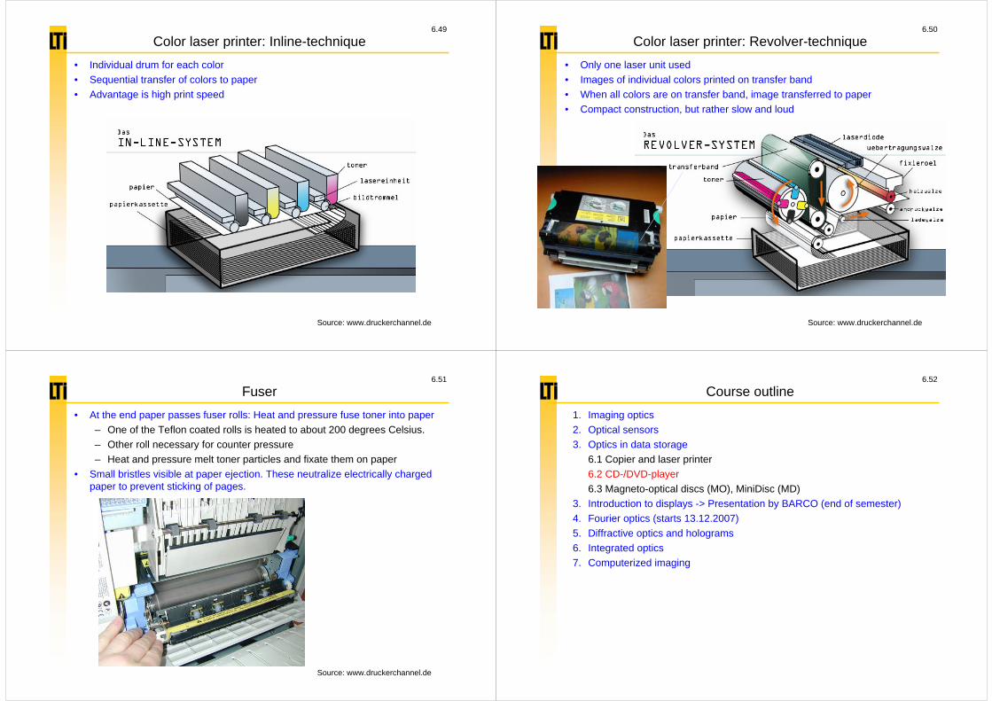
Color laser printer: Inline-technique • Individual drum for each color• Sequential transfer of colors to paper• Advantage is high print speed
Source: www.druckerchannel.de
6.50
Color laser printer: Revolver-technique• Only one laser unit used• Images of individual colors printed on transfer band • When all colors are on transfer band, image transferred to paper• Compact construction, but rather slow and loud
Source: www.druckerchannel.de
6.51
Fuser• At the end paper passes fuser rolls: Heat and pressure fuse toner into paper
– One of the Teflon coated rolls is heated to about 200 degrees Celsius. – Other roll necessary for counter pressure– Heat and pressure melt toner particles and fixate them on paper
• Small bristles visible at paper ejection. These neutralize electrically charged paper to prevent sticking of pages.
Source: www.druckerchannel.de
6.52
Course outline1. Imaging optics2. Optical sensors3. Optics in data storage
6.1 Copier and laser printer6.2 CD-/DVD-player6.3 Magneto-optical discs (MO), MiniDisc (MD)
3. Introduction to displays -> Presentation by BARCO (end of semester)4. Fourier optics (starts 13.12.2007)5. Diffractive optics and holograms6. Integrated optics7. Computerized imaging

6.53
Classification of data storage I
• Mass storage: Storage medium and access unit separate
• „random-access“-storage: Storage medium and access unit joined
6.54
Classification of data storage IIMass storage
• One or more access units and information saved on one or more storage units
• Data access by positioning of access unit onto storage unit
• Data exchange using different physical transactions, e.g., mechanical, optical, magnetic fields, electric fields.
• Access times for HDD are a few milliseconds, for CD/DVD/MO ca. 100 milliseconds
„random-access“-storage
• Access using matrix of conductors. Storage medium located at cross points
• Data access by electrical addressing of rows and columns in random order
• Electronic data exchange.
• Access times of few nanoseconds.
Source: Waser, „Nanoelectronics and Information Technology“
6.55
How is data stored on CD?• Digital data saved in continuous spiral
on CD• Data saved as bits in pits
• Height profile coated with reflective layer to increase intensity of reflected light
Sources: www.howstuffworks.com;www.physics.udel.edu/wwwusers/watson/scen103/less-cd.html
6.56
Fabrication of CD I• Glass master fabricated by exposure of photo resist • By galvanization (electrochemical process) 3-6 molds are fabricated
Source: www.ee.washington.edu/conselec/CE/kuhn/cdaudio/95x6.htm

6.57
Fabrication of CD II
Source: www.ee.washington.edu/conselec/CE/kuhn/cdaudio/95x6.htm
• After two more galvanic molds resulting metal stampers („Sons“) used to fabricate CDs using inexpensive die casting in polycarbonate (1.2 mm).
• At the end surface is coated with metal (Ag,Al,Au,Cu 50-100 nm), and protective layer (1-30 µm). Label is applied.
6.58
Exercise: Layout of CD-player
www.howstuffworks.com
Source: hyperphysics.phy-astr.gsu.edu/hbase/audio/cdplay.html
12
3
4
5
6
• How does a CD-player work?– What are components 1 to 6?– What function do they have?
6.59
Circuit diagram for photodiode
• Tracking
• Data signal
• Auto focus
Source: Imlau
6.60
Layout of CD-player• Optical beam path consists of laser diode, grating, polarizing prism, λ/4-
waveplate, various lenses and photodetector.
www.howstuffworks.com
Source: hyperphysics.phy-astr.gsu.edu/hbase/audio/cdplay.html

6.61
Reading data I
Source: hyperphysics.phy-astr.gsu.edu/hbase/audio/cdplay3.html
• Data read by laser (780 nm) through polycarbonate-substrate.
– Laser diameter at focus is 1.7 µm on reflective coating.
– Beam enters through substrate with diameter of 0.8 mm. Thus, dust or small scratches have no influence.
6.62
Reading data II• As all areas of CD are metal coated, reflectivity does not change with position.• Signal due to constructive or destructive interference.
LandPit
125 nm = λ/4
– „Pits“ (actually mounds) have depth of exactly λ/4 in polycarbonate.
– 780 nm/(4*1.55)=125.8 nm.
Source: www.howstuffworks.com; hyperphysics.phy-astr.gsu.edu/hbase/audio/cdplay3.html
– Half the beam reflected from „Land“ other half from „Pit“causes destructive interference in vertical direction due to 180° phase shift.
– If beam completely reflected from „Land“, constructive interference results.
6.63
Reminder: Polarization• Linearly polarized light is plane wave with fixed orientation of electric field • Circularly polarized light may be described by two plane waves with equal
amplitudes and 90° phase difference.
Source: hyperphysics.phy-astr.gsu.edu/hbase/phyopt/polclas.html
6.64
Polarizing beam splitter• Reflected light passes to photodetector and not back to laser diode due to
polarizing beam splitter and λ/4-Wellenplatte.
Source: hyperphysics.phy-astr.gsu.edu/hbase/phyopt/polclas.html

6.65
Focusing of laser beam I
• Objective lens focuses laser beam onto active layer.
• Due to circular aperture beam exhibits Airy-pattern.
• Beam is diffraction limited.
λ = 780 nmn = 1.5NA = 0.45 (in air)d = 1.3*10-6 mδ = 7.7*10-6 m
Source: Imlau
Source: www.ee.washington.edu/conselec/CE/kuhn/cdaudio/95x6.htm
6.66
Focusing of laser beam II• As planarity of CD is ca. 50 µm and „Wobble“ is ca. 100 µm continuous
refocusing is necessary to prevent crosstalk.• Focusing achieved with astigmatic lens (Combination of spherical objective
lens and cylindrical lens in front of detector) and quadrant detector.
Source: www.ee.washington.edu/conselec/CE/kuhn/cdaudio/95x6.htm
6.67
Astigmatic lens combination• Astigmatic lens combination causes only at correct spacing round shape. • Quadrant detector used to analyze beam shape
Source: www.physics.udel.edu/%7Ewatson/scen103/cd-astig.html
6.68
CD too close
Source: www.ee.washington.edu/conselec/CE/kuhn/cdaudio/95x6.htm

6.69
CD too far
Source: www.ee.washington.edu/conselec/CE/kuhn/cdaudio/95x6.htm
6.70
Autofocus
• Quadrant detector allows for simultaneous reading of data and generation of autofocussignal.
• Objective lens adjusted fast and precise with moving coil.
Source: www.ee.washington.edu/conselec/CE/kuhn/cdaudio/95x6.htm
Source: www.physics.udel.edu/wwwusers/watson/scen103/less-cd.html
6.71
Rotation of CD• Data on CD read with constant linear velocity of 1.3 m/s.• Due to constant linear velocity, angular velocity needs to be reduced from 500
RPM on the inside to 200 RPM on the outside.
Lead-Out
Lead-InData Area
Source: Waser: „Nanoelectronics and Information Technology“
6.72
Tracking I• During reading of CD optical head needs to be kept on spiral track.
– Accomplished with „Three-beam-tracking“.• Grating generates side beams around main beam.
Sources: www.ee.washington.edu/conselec/CE/kuhn/cdaudio/95x6.htm;hyperphysics.phy-astr.gsu.edu/hbase/phyopt/phopic/gratinghene2.jpg

6.73
Tracking II• Side beams fall between data tracks and are measured with two extra
detectors.
Source: www.ee.washington.edu/conselec/CE/kuhn/cdaudio/95x6.htm
6.74
Tracking III• If signal intensity of side beams is equal, tracking is adjusted correctly.• Tracking done with servo drives.
Source: www.physics.udel.edu/%7Ewatson/scen103/cd-tracking.html
6.75
How may the data density be increased?• Data density given by:
– Thus, bits should be chosen as small as possible for high data density.
• Resolution determines minimum size of bits:
– n*sin(α)=NA is numerical aperture of objective (n=1, as objective in air).
• To achieve high data density, wavelength should be small and NA large!
min 1.222 sin
yn
λα
=
Source: www.ee.washington.edu/conselec/CE/kuhn/cdaudio/95x6.htm
AreabitsD D
#2 =
6.76
Comparison CD and DVD
• For DVD smaller wavelength and larger NA is used. Also number of layers is increased to increase data density.
Source: Waser: „Nanoelectronics and Information Technology“

6.77
DVD Formats
Distance between double-layerlayers: 55 +/- 15 µm
Source: Waser: „Nanoelectronics and Information Technology“
6.78
Comparison CD and DVD
NA 0.45 0.6
2/1
Source: Waser: „Nanoelectronics and Information Technology“
6.79
Comparison CD - DVD - Blu-Ray
1.2 mm substrate
0.6 mm substrate
0.1 mm cover / 1.1 mm substrate
λ = 780 nmNA = 0.45
0.65 GBytes
CD DVD Blu-Rayλ = 650 nm
NA = 0.64.7 GBytes
λ = 405 nmNA = 0.85
25 GBytes
© Philips Research
6.80
Writable CDs and DVDs• The following categories are distinguished:
– Prewritten CDs and DVDs are read-only– WORM (write once read many): may be written once and read many
times, e.g., CD-R– R/W (read/write): maybe written and read many times
• Most important criterion for writable CDs and DVDs is that they may be read in conventional CD- and DVD-players– As in conventional read-only CDs and DVDs the reflection properties need
to be changed.

6.81
Methods for writable CDs/DVDs Ia) Burning of holes in thin metal layer (e.g., Tellurium due to low melting
point)
b) Blister formation upon heating
Source: Imlau
Source: Imlau
6.82
Methods for writable CDs/DVDs IIc) Thermo-plastic methods
d) Change of texture
Source: Imlau
Source: Imlau
6.83
Methods for writable CDs/DVDs IIIe) Chemical change of dye layer -> used in CD-R
e) Phase change from crystalline to amorphous -> used for DVD-R/W
Source: Imlau
computer.howstuffworks.com/cd-burner.htm/
6.84
CD-R: Tracking and Timing• Pre-groove allows for tracking.• Additionally pre-groove has „Wobble“ superimposed, a 22.05 kHz sinusoidal
deviation from track center with 30 nm amplitude. This allows for adjustment of writing speed.
www.chipchapin.com/CDMedia/cdr2.php3

6.85
DVD-R/W• Rewritable DVDs based on reversible phase change of medium by heating
with laser beam.
Waser: „Nanoelectronics and Information Technology“
Tm: Melting temperatureTx: Crystallization temperature
6.86
Phase Change Media I• X-ray diffraction shows different structure of amorphous and crystalline layer
of Ge2Sb2Te5.
Waser: „Nanoelectronics and Information Technology“
6.87
Phase Change Media II
• Amorphous and crystalline layer have different optical properties.
• Data may be coded by reflectivity.
Waser: „Nanoelectronics and Information Technology“
6.88
DVD-R/W: Layer sequence
• Dielectric layers on both sides of active layer ensure maximum energy absorbance and protect active layer.
• Tracking and timing again by use of pre-groove with „wobble“.
www.digitaldrives.com/Sections/TechReferences/Sources/DVD-RW%20Standard

6.89
Course outline1. Imaging optics2. Optical sensors3. Optics in data storage
6.1 Copier and laser printer6.2 CD-/DVD-player6.3 Magneto-optical discs (MO), MiniDisc (MD)
3. Introduction to displays -> Presentation by BARCO (end of semester)4. Fourier optics (starts 13.12.2007)5. Diffractive optics and holograms6. Integrated optics7. Computerized imaging
6.90
Magneto-Optical Discs (MOD), MiniDisc (MD)
• Data stored in small ferromagnetic domains that may be written and erased– Ferromagnetic domains are volume elements of homogeneous orientation
and magnetization. • Generation of domains by combination of light and magnetic field. Light heats
material locally.
Waser: „Nanoelectronics and Information Technology“
– Principle of MOD investigated in 70th
– Announced with CD in 1982
– First commercial MOD in 1988
6.91
MOD: Reading• Magneto-optical Kerr-effect (MOKE) causes slight rotation of polarization state
of reflected compared to incident light (ca. 0.5°).– Sign depends on orientation of ferromagnetic domain
• Polarizer converts polarization modulation to amplitude modulation.
Waser: „Nanoelectronics and Information Technology“
6.92
MOD: Writing• For applied magnetic field larger than coercivity Hc change in domain
orientation achieved
www.twysted-pair.com/hyster1.htm
Hc
Hc
• In MODs materials are used whose Hc depends strongly on temperature.– At room temperature and
heating be weak read laser beam, Hc should be large to keep data state.
– Upon heating with intensive write laser beam, Hc should be small to write data with applied magnetic field

6.93
MOD: Materials• Only a magnetization orthogonal to layers may be read with typical reading
configurations.– Most materials have orientation of domains parallel to layer (shape
anisotropy FA)
• Only materials with larger orthogonal anisotropy Ku than shape anisotropy FA may be used: Ku>FA.– This is the case e.g. for Co. Co
has small magnetization though. – Better is combination of several
materials, e.g., TbFeCo.
6.94
Layer sequence of MOD • Al-layer reflects light. Light passes TbFeCo-layer twice.• Si3N4-layer prevents water absorption in the TbFeCo-layer and serves as
antireflective layer.
Waser: „Nanoelectronics and Information Technology“
6.95
Comparison MO-disc and DVD-RAM• 3,5" MO-Disk
– At maximum 2,3 GB, – 16 EUR– Operating system recognizes
MOD as hard drive– Higher physical data security
• MOD insensitive to light• MOD insensitive to
temperature up to ca. 100 °C
• DVD-RAM – 4,7 GB– 2,40 EUR– Faster data transfer– DVD-RAM-burner cheaper– DVD-RAM sometimes linked as
DVD-burner
Source: http://de.wikipedia.org
6.96
Compilation of questions• Name three methods for optical distance measurements! Explain one in detail!• For which distances may time-of-flight measurements be used?• What is an autocollimator?• How does an optical mouse work?• When does speckle occur?• How does a photocopier work?• How does a laser printer work?• Sketch and explain the laser scanner unit of a laser printer!• What are differences between mass storage and „random-access“-storage?• Sketch a CD-player and explain the individual components! • How is the data coded on a CD?• How is the laser beam kept on track during CD-reading? • How may the data density be increased?• Name three methods for realizing writable CDs! • How is the data stored in an MOD?• What are the parts of an MOD-player?• Name an advantage of an MOD compared to a DVD-RAM!