optical fibre cable accessories - indian railways
TRANSCRIPT
OFC ACCESSORIES March ’2004
OPTICAL FIBRE CABLE ACCESSORIES
1. Termination box
1.1 Description
Optical fibre termination box acts as an interfacebetween the optical fiber cable coming from the lineside & the pigtails to be taken to the fiber distributionframe i.e. it is made for terminating the OFC from thefield and connecting it to pigtail by splicing. Theother end of the pigtail having the optical connector isterminated inside the fibre distribution frame. It issimilar to MDF in telephone exchanges.
Fibres from both of these after fusion splicing arekept safely in the cassettes provided inside this box.The termination box also acts as a storage unit forextra length of fibre from the line side & the pigtails.It serves for bunching & rerouting of optical fibrecable.
1.2 Construction
Optical fibre termination box is made for mounting onwall or on 483 mm wide instrument cabinet racksmade of steel frame and is suitable for generalweather and environmental conditions prevailing incountry. It is suited for loose tube, central tube as wellas slotted core type of optical fibre cable.

CAMTECH/S/2004/OFCASC/1.0
OFC Accessories March ’2004
2
The housing of termination box is of rugged design. Itis made of M.S.sheet and welded electrically bymachines to take care the requirement of transport,installation, operation and maintenance. The entirebox is painted with epoxy base white paint to give asmooth, durable and pleasing finish.
The wall mounted type termination box has frontaccesses. By removing the front cover having fourcaptive screws at each of the four corners. It isdesigned for easy installation on the wall or 483 mmstandard instrument racks made of steel. The generalarrangement of the termination box is shown infigure 1.
OFC from the field enters the termination box fromthe two holes at the bottom fitted with rubberdiaphragm in each at the inlet hole.
The cable is clamped at the first cable clamp. Thesecond clamp has been provided with two-fibreguides and clamping facility to clamp inner strengthmember and allow easy exit of all loose tubes andtransports tube through relief.
The splice tray is made of ABS material with capacityto hold 12 splices are provided without any unduepressure on the fibre protection sleeve. A cover isprovided on the last splice tray made of ABS material.The splice trays are stacked one on the top of theother. All slacked splice trays are hinged together toopen up like the pages of book.

CAMTECH/S/2004/OFCASC/1.0
OFC Accessories March ’2004
3
Figure – 1

CAMTECH/S/2004/OFCASC/1.0
OFC Accessories March ’2004
4
A stainless steel wire mechanism has been providedfor fixing and holding of splice tray. This mechanismalso adds to the convenience in managing the spliceetc. because the splice tray rests firmly on thismechanism.
The splice holder is made to house fusion type ofjoints with fibre protection sleeve and strengthmember.
The splice tray shall have the fibre from the cablesjoined in a predetermined order with the respectivepigtails.
Holes have been provided at both the ends of thesplice tray to use a plastic clamping strap to hold andclamp sleeved fibre or pigtails.
The splice tray provides facility for rejoining,rearrangement or realignment of the fibres.
Each fibre coming out of the cable is spliced with apigtail and these spliced joints inside fibre protectionsleeve are securely push fitted in the splice holder.Excess length of the fibre can be stored in the splicetray by holding the stored fibre’s loop through guideways in the splice tray and self-adhesive pads, if sorequired.
Generally up to 6 splices are stored in each splice trayresulting in the connection of up to 24 optical fibres tothe respective pigtails.

CAMTECH/S/2004/OFCASC/1.0
OFC Accessories March ’2004
5
The pigtails are taken out through outlet holesprovided with plastic glands similar to the ones usedon fibre distribution frame so that, if need be, theflexible plastic conduit can be fitted betweentermination box & fibre distribution frame to coverthe pigtails. This feature is an extra cost option andsupplied against specific order. It is expected that theun-connectorised end of the pigtail will be insertedthrough the plastic gland for fusion with the fibrecoming out of OFC to avoid any possible difficulty ofpassing the connectorised end with FC/PC connectorthrough the cable gland hole. All entry and exit holesremain normally closed except when in use.
Suitable fibre identification ferrules are also providedfor ease of identification, installation andrearrangement of pigtails/optical fibres.
1.3 Specifications
1.3.1 Mechanical Dimension :
Height : 310 mm + 1 mm
Width : 482.6mm + 1 mm(With collar for rack mounting)
Depth : 100 mm + 1 mm
Thickness : > 2 mm

CAMTECH/S/2004/OFCASC/1.0
OFC Accessories March ’2004
6
Wall mounting hole : 324(W)+ 2mm x 196(H)+ 2 mmCentre distance for
hole of dia 8.7 mm.
For 19” rack mounting hole : 465 mm + 1.6 mm
1.3.2 Capacity of the optical fibre cable termination box
Line side : Maximum capacity to terminate 2OFC through two entry holes fittedwith rubber diaphragm to suit thecable up to 20 mm dia.
Equipment Side : Maximum capacity to take out andterminate up to 48 pigtails each ofdia 3 mm max through six separateholes.
1.4 Capacity of Splice Tray (Fibre organiser)
Number of splice trays provided in : 4 nos.Termination box.
Number of fusion type of splices : 12 nos.With fibre protection sleeves thatCan be stored in each splice tray

CAMTECH/S/2004/OFCASC/1.0
OFC Accessories March ’2004
7
1.5 Installation Procedure
1.5.1 Mounting
Optical fibre termination box is mounted on the wallor on the 483 mm ( 19 inch ) wide standard rack suchthat the front panel is easily accessible with cableentry from the bottom.
1.5.2 Cable end preparation
Before starting the cable entry in Optical fibretermination box, cable end is to be prepared. Thecable end preparation procedure is available from thesupplier. It is extremely important at this stage toprotect the bare fibres, which get exposed afterfollowing the cable end preparation specially in caseof slotted core cable.
1.5.3 Cable Entry
Before inserting the cable in Optical fibre terminationbox the rubber diaphragm at cable entry hole ispierced which will allow the cable entry in Opticalfibre termination box. Normally these opening areblocked, therefore, it is necessary to pierce theblockade before the cable entry.

CAMTECH/S/2004/OFCASC/1.0
OFC Accessories March ’2004
8
1.5.4 Cable end strength member clamping
After the above step the relevant cable should beclamped as shown in figure 2.

CAMTECH/S/2004/OFCASC/1.0
OFC Accessories March ’2004
9

CAMTECH/S/2004/OFCASC/1.0
OFC Accessories March ’2004
10
Figure – 2

CAMTECH/S/2004/OFCASC/1.0
OFC Accessories March ’2004
11
In case of slotted core cable where, if, 12 grooves areon the slotted core then after all the optical fibres havebeen sleeved, they are placed individually in each ofthe 12 grooves and then fixed in the position with thesleeve clamping rings as shown in figure 2 at C.
The fibre in sleeves also called transport tubes arerouted through several plastic fibre guide postsmounted in Optical fibre termination box. All excesslength of transport tube is accommodated betweenthese guideposts and finally brought into the selectedsplice tray. The transport tube is clamped at the entrypoint of splice tray using plastic clamping strapprovided as accessory. Bare fibre will now come outof these transport tube and ready for splicing.
1.5.5 Splicing
Splicing of the optical fibre from the cable to the fibreof the pigtails is the most important part of theinstallation.
A table of a height approximately equal to the heightof the lower part of the Optical fibre termination boxis placed adjacent to it. Splicing machine is placed onthe table, the required splice tray is opened simply byreleasing the stainless steel wire mechanism from itsspring catch.
Splice the fibre of the pigtails with the fibre endscoming out of the cable in a sequence by usingsplicing machine then push fit the fused splice with its

CAMTECH/S/2004/OFCASC/1.0
OFC Accessories March ’2004
12
protection sleeve in the splice tray at the groovesprovided in the spiced holder. The additional lengthof the fibre can be stored in the splice tray as shownin the figure 3, in such a way that the fibre does notbend below the critical value of 75 mm dia. Theprocess is repeated till all the splices have been storedin splice trays and splice trays finally placed backinside the termination box in a stack. When all thefour splice trays have been stacked as above the stackis fixed with stainless steel wire mechanism.
Figure – 3

CAMTECH/S/2004/OFCASC/1.0
OFC Accessories March ’2004
13
1.5.6 Organisation of pigtails exit
The bunch of pigtails entering in the Optical fibretermination box through PVC glands are routedthrough plastic guide posts provided inside thetermination box which help in storing spare length ofpigtails. These pigtails are then routed to the fibredistribution frame. In order to give protection to thepigtails either a flexible plastic conduit is providedwhich fits into the pigtails outlet gland provided onthe termination box or bunch of pigtails are tiedtogether with PVC strap and tape as shown in figure4. The plastic flexible conduit and PVC strip tie canbe provided if separately ordered. During the handlingof the fibres and pigtails care should be taken thatthey are not stretched or bent beyond the limits.
Figure – 4

CAMTECH/S/2004/OFCASC/1.0
OFC Accessories March ’2004
14
2. Fibre Distribution Frame ( FDF )
2.1 Description
Optical Fibre distribution frame is designed fororganising the optical fibre pigtails from the fieldcable side to the optical fibre patch cords on theexchange equipment side. The inputs of fibredistribution frame are fibre optic pigtails originatingfrom the termination box and the outputs are the fibrepatch cords connected to optical line terminatingequipment. Fibre distribution frame also facilitatesthe connection of any optical line test equipment totest the proper functioning of field cable or theexchange equipment.
Some space has provided to store the extra length ofpigtails and patch cords. Fibre distribution frameprovides following facilities:
i. To terminate the optical fibre pigtailsoriginating from termination box.
ii. To connect the fibre optic equipment.
iii. To store the excess lengths of pigtails andpatch cords.
A verity of connectors and accessories options areavailable for compatibility of existing or futureoptical fibre system. Each fibre distribution frame hascapacity up to 24 numbers of FC/PC type optical
CAMTECH/S/2004/OFCASC/1.0
OFC Accessories March ’2004
15
adopters where pigtails or patch cords could beinterconnected to the respective equipment.
In case 48 fibres are to be handled, two units of fibredistribution frame are to be used. They can bemounted either back to back on a 483 mm widestandard instrument rack or side by side on the wall.
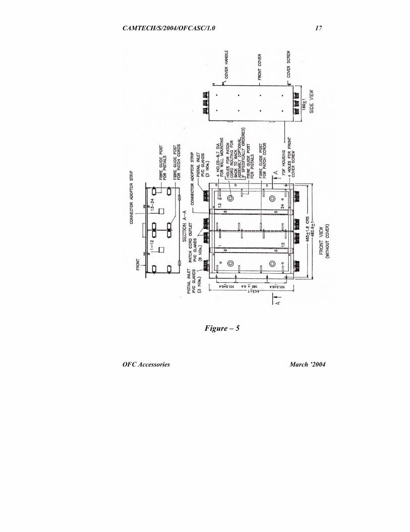
2.2 Construction
Fibre distribution frame is designed and made inhousing compatible to 483 mm (19 inch) wideinstrument rack or wall mounting. It is made out ofsteel sheet to provide a robust and reliableconstruction for operation, adjustment, replacement,storage, transport and is not effected by minor fire.The general arrangement of Fibre distribution frameis shown in figure 5.
The Fibre distribution frame is designed to meet thegeneral weather and climatic conditions. The interiorof Fibre distribution frame has front access and it canbe mounted on a 483-mm wide standard instrumentracks. In addition, four holes of 8.7 mm dia areprovided to fix the FDF on the wall, if required.

CAMTECH/S/2004/OFCASC/1.0
OFC Accessories March ’2004
16
CAMTECH/S/2004/OFCASC/1.0
OFC Accessories March ’2004
17
Figure – 5

CAMTECH/S/2004/OFCASC/1.0
OFC Accessories March ’2004
18
The front of FDF has four cover screws at each of thefour corners as shown in figure 6.
409±
2
Figure – 6
After opening the front cover an access to opticalconnector adopters and fibre guide posts is obtained.Two set of vertical fibre guide posts are fitted insidethe FDF on both the side walls and middle plate of theFDF. The F.O. connector adopter holding angle stripsare fitted between the top/ bottom walls of the fibredistribution frame. If required and specially orderedthe back wall of FDF is provided with four blankedoff holes to route fibre pigtails / patch cords to or

CAMTECH/S/2004/OFCASC/1.0
OFC Accessories March ’2004
19
from other FDF mounted back to back in aninstrument rack.
Each of FO adopter holding angle strip are modular inconstruction and have a provision for 12 nos. fibreroutes. Two such fibre optic adopters can be providedin each Fibre distribution frame making the totalcapacity to 24 nos. of fibre routes.
The top and bottom walls have 12 holes, in which 3holes on the left are meant for incoming fibre opticpigtails and the other for outgoing fibre optic patchcords. Each hole is provided with a PVC gland whichpermits up to 4 connectorised pigtails / patch cords toenter through these holes.
Pigtails coming out of the termination box enter intothe FDF through inlet holes and are routed to thevertical fibre guide posts fitted inside FDF on the leftwall. These pigtails travel downward in theguideposts and take upward turn to form a completeloop thus storing the extra length of pigtail aroundfibre guide posts. The connector of the pigtail isterminated on the desired connector adopter aftertaking it out from the nearest guide post. On the otherside of connector adopter a converse method isadopted to take out the patch cords. The routing of thefibre is such that it does not bend below the criticalbend dia. of 75 mm.

CAMTECH/S/2004/OFCASC/1.0
OFC Accessories March ’2004
20
2.3 Specifications
2.3.1 Mechanical Dimension :
Height : 443 mm + 1 mm
Width : 482.6mm + 1 mm
Depth : 180 mm + 1 mm
Thickness : > 2 mm
Wall mounting hole : 324(W)+ 2mm x 325(H)+ 2 mmfor hole of dia 8.7 mm.
For 19” rack mounting hole : 465 mm + 1.6 mmdistance centre
2.3.2 Capacity
Line side : Maximum capacity to terminate 24pigtails or patch cords throughdifferent suitable inlets. Eachpigtail/patch cord inlet shall caterfor 4 nos of FC/PC typeconnectorised pigtails or patchcords each having diameter of 3mm maximum..
Equipment Side : Same as on line side.

CAMTECH/S/2004/OFCASC/1.0
OFC Accessories March ’2004
21
2.3.3 Connector adopters Type of connector – FC/PC to FC/PC or as specified.
Opening temperature range - 0 to 50 deg. C.
2.4 Installation
2.4.1 Grouting of FDF on wall
Position the FDF at the predetermined location wheregrouting bolts have been fixed at a hole centredistance of 324 ( width) + 2mm X 325 (Height) +2mm and tighten the FDF using four plain washer,spring washer and nut.
2.4.2 Entry of pigtails and patch cords
Not more than 4 pigtails / patch cords of diameter 3mm maximum are threaded through the inlet and theoutlet holes respectively via plastic glands providedon the top and bottom plate.
In order to give protection to the pigtails or patchcords either a flexible PVC conduit is provided whichfits in to the cable inlets provided on the top orbottom plate and the termination box or bunch ofpigtails coming out of each hole is tied together withPVC tape. The PVC flexible conduit can be providedwith FDF. During the handling of the pigtails / patchcords care is to be taken that they are not stretched orbent beyond the limits.

CAMTECH/S/2004/OFCASC/1.0
OFC Accessories March ’2004
22
2.4.3 Mounting on 483 mm rack
Mount the Fibre distribution frame on a standardinstrument cabinet rack using 4 nos of screws withwasher on either side of the front of FDF.
Take out the connector mounting angle from the FDFby loosening three of its mounting screws and slidingit upward till the screw head is cleared through thekey hole provided. Fix the FC / PC adopters on theangle and replace it at its original position and tightenthe screw.
Do not remove the protective caps over theconnectors till they are ready for connection in orderto avoid any dust or foreign particle sticking to thepolished faces of the connectors. All the pigtails Patchcords and end connector faces be cleaned usingsuitable solvent and lint free tissues beforeconnection.
3. Fiber Distribution Management System (FDMS)
Fiber distribution management system ( FDMS) isdesigned to full fill the needs of modern opticalcommunication system. It is made to terminate a largenumber of optical fibre cables and manage thesubsequent distribution of the fibres. It is acombination of optical termination box & FDF.
CAMTECH/S/2004/OFCASC/1.0
OFC Accessories March ’2004
23
3.1 Construction
The Fibre distribution management system is compactand robust to meet with the conditions of operation,adjustment, storage and transport. It is made of fireretarding material and can withstand salineatmosphere.
The basic unit of FDMS is consist of sub-racksuitable for 19 inch standard rack mounting havingtwo pull out shelves. One shelf is called “splicingShelf” and the other is called “ Patching Shelf”.
The basic building block of FDMS is modular innature and is capable of storing up to 24 optical fibresplices and subsequently patching them with the opticfibre patch cords. Additional units of FDMS can bemounted on the 19-inch rack. At the back of Fiberdistribution management system two stainless steelclamps are provided to clamp up two numbers ofoptical fibre cables and their strength members.
The optical fibres in loose tubes / transport tubeseminating from the cable are passed through a flexiblePVC duct which terminates on the splicing shelf. Theloose tubes are then stored around self aligning guideposts and terminated on the selected splicing tray.There are four splice trays provided on the splicingshelf which open up like the pages of a book and heldin closed position with spring loaded catch. The topsplice tray is covered with a cover, which is tightenedwith a pair of captive screws. The ends of loose tubes

CAMTECH/S/2004/OFCASC/1.0
OFC Accessories March ’2004
24
are fastened to the selected splice tray and fibreseminating from the loose tubes are stored in the splicetray and identified with numbered ferrules providedas accessories.
The pigtails are threaded into the optical fibre sub-rack, has also its fibre end available in the splice tray.The fibre from the cable and the pigtail are splicedand fused together. The fused joint is then spliced intothe pre threaded splice protection sleeve and exposedto hot air so that it shrinks and grabs the fibres & jointfor safety. It is then stored in the slot provided on thesplice tray. Such 12 splices can be stored in eachsplice tray. The process is repeated for other fibreends of the OFC and the corresponding pigtail.
The connectorised end of all the pigtails areterminated on the FC/PC adopters fixed in thepatching shelf. The other end of the FC/PC adoptersare connected the patch cord, which eventuallyterminates on OLTE.
The general arrangement of optical fibre distributionmanagement system is shown in figure 7.

CAMTECH/S/2004/OFCASC/1.0
OFC Accessories March ’2004
25
Figure – 7

CAMTECH/S/2004/OFCASC/1.0
OFC Accessories March ’2004
26
The Fiber distribution management system is fullyaccessible from front side and is mounted on a 19inch standard rack using the mounting hardwareprovided with the optic fibre sub-rack. The design issuch as to manage the slackness of pigtails, fibres orpatch cords by providing adequate storage space inthe shelves so that bend radius at any place does notfall below 35 mm or 70 mm dia.
Identification arrangement for optical fibre cable,optical fibre, adopters, pigtails & patch cords is alsoprovided. The Fiber distribution management systemmay be supplied by supplier with 24 numbers ofoptical fibre pigtails having FC / PC connector at oneend and 24 numbers of FC / PC adopters.
3.2 Specifications
3.2.1 Mechanical Dimension :
Height : 177 mm + 2 mm
Width : 430 mm + 3 mm(With out collar )
Depth : 275 mm + 3 mm
Thickness : > 1.6 mm
Width of sub rack : 482.6 mm + 1 mm( with collar )

CAMTECH/S/2004/OFCASC/1.0
OFC Accessories March ’2004
27
3.2.2 Capacity of the optical fibre cable termination
Line side : Maximum capacity to terminate 2OFC each of < 20 mm nominaldia.
Equipment Side : Maximum capacity to take out andterminate up to 24 pigtails / patchcords each of dia 3 mm and havingFC/PC connector.
3.2.3 Capacity of Splice Tray
Number of splice trays provided in : 4 nos.Splicing shelf.
Number of fusion type of splices : 12 nos.With fibre protection sleeves thatCan be stored in each splice tray
3.3 Capacity of Patching Shelf
Number of optical fibre circuit : 24 Nos.
Number of FC/PC adopters : 24 Nos.
Maximum capacity to accommodate3 mm dia patch cords : 24 Nos.

CAMTECH/S/2004/OFCASC/1.0
OFC Accessories March ’2004
28
3.4 Installation Procedure
Fibre distribution management system is mounted on19-inch standard rack.
3.4.1 Cable End Preparation
Before starting to fix the optical fibre cable with itsclamp provided at the back of the FDMS unit, cableends preparation and stripping of cable has to becompleted according to the procedure as supplied bysupplier.
3.4.2 Cable Entry
Cable is clamped at the cable clamp provided at theback of FDMS such that it is firmly gripped at thecable clamp and the strength member at strengthmember clamp as shown in given figure 8.
The loose tubes are first threaded in to the flexiblefibre duct through the gland provided near thestrength member clamp and taken in to the splicingshelf and stored. The end of the loose tubes near theentry gland of flexible duct are tied using the plasticclamping strap, provided with the accessories, suchthat the bend radius does not fall below 35 mm. Theother end of the loose tube is fastened to the splicetray and fibres are taken out from the loose tube andstored in the splice tray. Each fibre is threadedthrough the numbered plastic ferrules foridentification.

CAMTECH/S/2004/OFCASC/1.0
OFC Accessories March ’2004
29
Figure – 8

CAMTECH/S/2004/OFCASC/1.0
OFC Accessories March ’2004
30
The un-connectorised end of the pigtail is enteredthrough the lower right hand slot on the optical fibresub-rack and brought to the splicing shelf where it isfastened to the splicing shelf using plastic clampingstraps.
The excess length of the pigtail is stored in splicingshelf around the fibre guides posts and finally its endis fastened to the selected splice tray using plasticclamping strap. The fibre eminating from this pigtailis fusion spliced with the selected fibre of the cable.The resulting fusion splice is stored in the splice tray.The process is repeated for other fibres and pigtails.
3.4.3 Splicing
The splicing of the optical fibre from the cable to thefibre of the pigtails is the most important part of theinstallation.
A table of suitable height is placed adjacent to FDMSrack. The splicing machine is kept on this table. Therequired splice tray is opened by simply pulling thespringed catch towards the operator.
Using the splice machine, splice the fibre of thepigtails with the fibre ends eminating from the cablein a sequence then push fit the joint with heat shrunksplice protection sleeve in one of the slot provided onthe spliced trays. Additional length of the fibre can bestored in the splice tray in such a way that the fibresdoes not bent below the critical bent diameter of 70

CAMTECH/S/2004/OFCASC/1.0
OFC Accessories March ’2004
31
mm as shown in the figure 9. The process is repeatedtill all the fibres are spliced and stored in the splicetrays.
Figure – 9

CAMTECH/S/2004/OFCASC/1.0
OFC Accessories March ’2004
32
3.4.4 Organisation of pigtails & patch cords
The connectorised end of the pigtail is routed to the“patching shelf” through the upper slot on the righthand side of the FDMS and terminated on the FC/PCadopters pre-fixed in the patching shelf. The excesslength of pigtails is stored in the splicing shelf and theends entering into the patching shelf are fastened to itusing plastic clamping strap. Once again care is to betaken that pigtail are not bent beyond the criticalvalue of 70 mm dia of bent. A small storage throughtwo guide posts is provided to shape the pigtails andensure bending radii. Each pigtail is tagged with aplastic identification tag to provide routeidentification.
The other end of the FC/PC adopter is connected toone end of the optical fibre cord. The extra length ofpatch cord is stored in the patching shelf using theouter loop formed by the guide posts. The patch cordcould be taken out from upper left side slot on FDMSside to OLTE or could be taken from the front asconvenient.
Care is to be taken while threading pigtails fromsplicing shelf to the patching shelf that a small loop isformed outside FDMS such that it provides thedesired length when any of the shelves are pulled out.All the pigtails could also be bunched together using aplastic clamping strap.

CAMTECH/S/2004/OFCASC/1.0
OFC Accessories March ’2004
33
4. Joint closure
4.1 Description
The optical fibre cable joint closure is used to connecttwo, three or more optical fibre cables of an opticalfibre route. Fibres of different cables are fusionspliced and kept safely inside the splice organizers(cassettes) provided inside the OFC joint closure. Theclosure is buried inside the earth or hanged on a polein case of arial cable.
Closures are two types, straight through Joint closure(SJC) & branched type joint closure (BJC). Closuresare sufficiently strong & robust to resist theenvironmental / weather effect. After assembly / heatshrinking it is moisture free, dust free & insect free.
4.2 Construction Details
It mainly consist of a moulded shell (pipeshaped with one end closed) with an end caphaving 4 parallel ports and 1 oval port for thecable entries / exits.
The end cap contains a base plate/main platewhich holds the sheath clamp, FRP holder andcassettes. At the other end of the end cap thereis an end disc which is also mounted on thebase plate itself. The cable is entered from theentry ports provided in the end cap and is

CAMTECH/S/2004/OFCASC/1.0
OFC Accessories March ’2004
34
gripped in the sheath clamp. FRP holder holdsthe FRP strength member of the cable. Aramidyarn holder, if needed can be mounted at theplace of FRP holder in case of mono tubecables.
The lower most cassette is mounted on thebase plate using screws and all other cassettesincluding cover is mounted by cassette pinsover each other. The cassettes can be mountedon both sides of the main plate/base plate.
The housing of the cassette is designed so asto ensure that fibres should have bendingradius of 37.5 mm or more.
Grounding strip made up of copper isprovided beneath the main plate/base plateover the entire length of the joint closure forenabling the splice closure to resists a currentsurge of 1000 amp. for 5 seconds in case ifcurrent surge in the cable due to lighteningetc.
The grounding terminal / port extends outsidethe body of the splice closure from wheregrounding may be done for main earthing inthe field.

CAMTECH/S/2004/OFCASC/1.0
OFC Accessories March ’2004
35
Figure – 10

CAMTECH/S/2004/OFCASC/1.0
OFC Accessories March ’2004
36
4.3 Installation procedure
These joint closures can be kept inside themanhole or mounted on to the pole in case ofaerial cable.
Firstly the cables are taken and insertedthrough the end cap using suitable inletsprovided.
Mark a length of 550 mm on the cable andfrom this point strip the cable to obtain thefollowing:
a) HDPE sheathing of minimum of 40mm length to be gripped in the sheath/sheath clamp.
b) FRP strength member of the cableapprox. 40 mm length to be held in theFRP holder which itself is 15 mmwide.
c) Loose tubes coming of the cablesshould be at least 150-200 mm long.
d) Loose tubes are stripped to obtain thefibre length of about 300 mm.
The cable is inserted through the cables entryports, the HDPE / Nylon sheath is grippedwith the sheath clamp and FRP strengthmember is gripped with the FRP holder.
The steel wires if present as strength memberare tied on the 0.8 mm holes provided on themain plate. For earthing the lugs are used withproper wire.

CAMTECH/S/2004/OFCASC/1.0
OFC Accessories March ’2004
37
The cassettes are used for housing fusionspliced joints after complete stripping andfusion splicing of the optical fibre.
5. Patch Cord
Patchcords are generally called jumper cables. Theseare available in different sizes such as 5 metre, 10metre, 20 metre, 40 metre or as per requirement.Patchcords have connectors on both sides and arenormally used for giving connections from fiberdistribution frame to the equipment. In figure 11given below simple sketches of pigtails and patchcords are shown.
Figure – 116. Pigtail
Pigtails have connector on one side and are used assingle fibre connection from cable by splicing in thetermination box. These are also available in differentsizes as required.

CAMTECH/S/2004/OFCASC/1.0
OFC Accessories March ’2004
38
Figure – 12
7. FC / PC Adopter
FC / PC adopters are used for connecting patch cordsand pigtails in the fibre distribution frames. Wheneverrequired to increase the capacity of fibre distributionframe, FC/PC adopters are used. These are availablein two types, one fitted with ceramic sleeve and theother fitted with Be-Cu sleeve.
8. Fibre Protection Sleeves
Fibre Protection Sleeves are used for splicing thefibres. They protect the fibre after splicing. These aresmall in size but has an important role. Fibreprotection sleeves are supplied with joint closure andtermination box as part of consumables in sufficientquantity.