optical measurement of acoustic drum strike … · optical measurement of acoustic drum strike...
TRANSCRIPT
Optical Measurement of Acoustic Drum Strike Locations
Janis SokolovskisCentre for Digital Music, School of EECS
Queen Mary University of LondonMile End Road, London, E1 4NS, UK
Andrew P. McPhersonCentre for Digital Music, School of EECS
Queen Mary University of LondonMile End Road, London, E1 4NS, UK
ABSTRACTThis paper presents a method for locating the position ofa strike on an acoustic drumhead. Near-field optical sen-sors were installed underneath the drumhead of a commer-cially available snare drum. By implementing a time dif-ference of arrival (TDOA) algorithm, accuracy within 2cmwas achieved in approximating the location of strikes. Thismethod could be used for drum performance analysis, tim-bre analysis and can form a basis for an augmented drumperformance system.
Keywordsaugmented drum, position sensing, optical sensors, TDOA,gesture capture
1. INTRODUCTIONPosition measurement of impacts on an acoustic drum hasapplications both for performance analysis and for extendedpercussion instrument performance, but few performance-ready solutions exist. Several commercial electronic drumpads offer forms of position measurement, but these lackthe same tactile response and richness of sound providedby a good acoustic drum. Measurements directly on anacoustic instrument require careful design in order to avoiddisrupting the player’s performance. Practical issues suchas transport and setup time should also be considered.
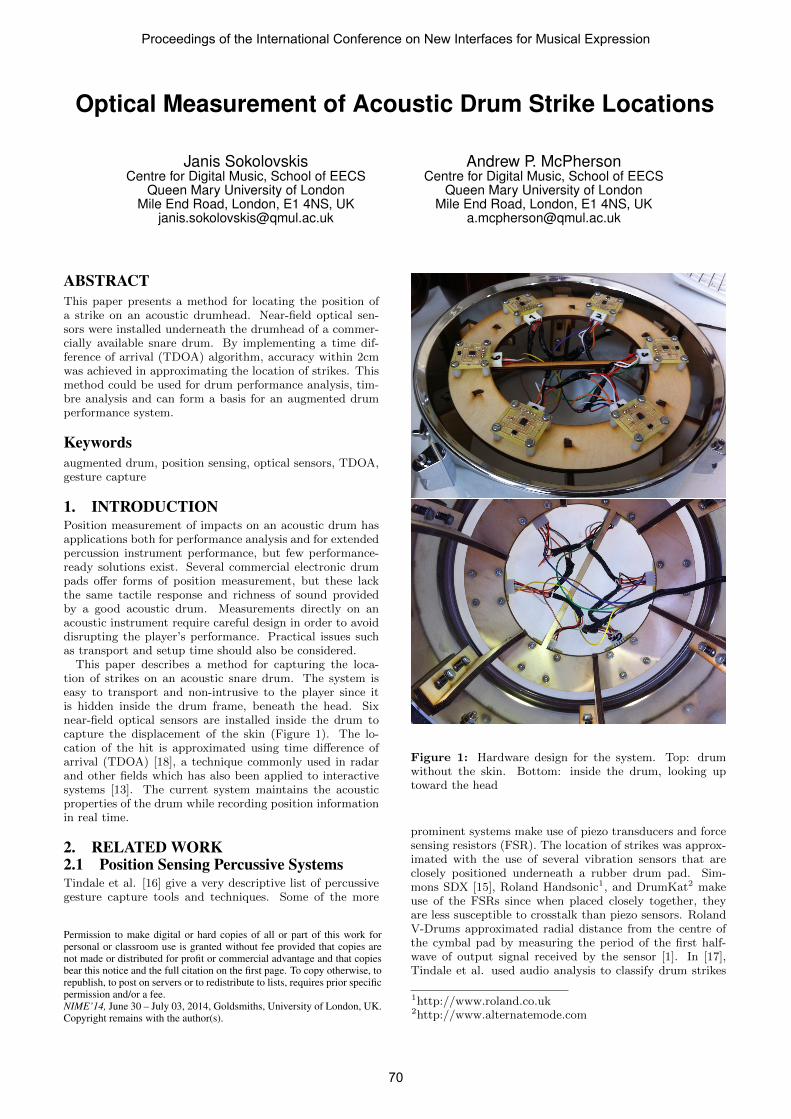
This paper describes a method for capturing the loca-tion of strikes on an acoustic snare drum. The system iseasy to transport and non-intrusive to the player since itis hidden inside the drum frame, beneath the head. Sixnear-field optical sensors are installed inside the drum tocapture the displacement of the skin (Figure 1). The lo-cation of the hit is approximated using time difference ofarrival (TDOA) [18], a technique commonly used in radarand other fields which has also been applied to interactivesystems [13]. The current system maintains the acousticproperties of the drum while recording position informationin real time.
2. RELATED WORK2.1 Position Sensing Percussive SystemsTindale et al. [16] give a very descriptive list of percussivegesture capture tools and techniques. Some of the more
Permission to make digital or hard copies of all or part of this work forpersonal or classroom use is granted without fee provided that copies arenot made or distributed for profit or commercial advantage and that copiesbear this notice and the full citation on the first page. To copy otherwise, torepublish, to post on servers or to redistribute to lists, requires prior specificpermission and/or a fee.NIME’14, June 30 – July 03, 2014, Goldsmiths, University of London, UK.Copyright remains with the author(s).
Figure 1: Hardware design for the system. Top: drumwithout the skin. Bottom: inside the drum, looking uptoward the head
prominent systems make use of piezo transducers and forcesensing resistors (FSR). The location of strikes was approx-imated with the use of several vibration sensors that areclosely positioned underneath a rubber drum pad. Sim-mons SDX [15], Roland Handsonic1, and DrumKat2 makeuse of the FSRs since when placed closely together, theyare less susceptible to crosstalk than piezo sensors. RolandV-Drums approximated radial distance from the centre ofthe cymbal pad by measuring the period of the first half-wave of output signal received by the sensor [1]. In [17],Tindale et al. used audio analysis to classify drum strikes
1http://www.roland.co.uk2http://www.alternatemode.com
Proceedings of the International Conference on New Interfaces for Musical Expression
70

according to timbre. With the use of machine learning theycould classify the radial position of a drum strike based onits spectral features.
There are only a handful of systems that attempt to solvethe issue of capturing position of a drum strike. An aug-mented djembe drum [10] made use of computer vision. Byinstalling a webcam underneath the skin of the drum thesystem was able to interpret shadow displacement into 3Dposition of the hand. The shortfall of systems using shadowsis the requirement of adequate lighting to be present dur-ing the performance. Similarly Gray et al. [5] augmented asnare drum to allow the performer to trigger audio and videosamples. To reinforce information obtained by the camera,the system also featured piezo transducer attached to thedrum skin and flex sensors embedded into the brushes.
Paradiso et al. [13] proposed a glass surface that could ap-proximate the location and distinguish different gestures bytheir acoustic features, knocks, metal taps and fist bashes.This was achieved by capturing their acoustical featureswith the use of piezo transducers. Lopes et al. [9] createda multi-touch surface which builds on the same principlebut with contact microphones instead and used Laser LightPlane for multi-touch. The system’s goal was to explore thepossibilities of integrating touch and sound to expand inputlanguage of surface interaction. Using the same methodwith addition of FSRs, McCloskey et al. [11] created a per-cussive performance surface. Ishii et al. [6] used an array ofmicrophones underneath a ping pong table to approximatethe location of ball impacts.
2.2 Optical Sensors in Musical InstrumentsRoland D-Beam is one of the commercial products that cap-tures performance gestures using infrared (IR) technology.The system can detect the distance between the hand andthe sensor. The distance can be mapped to parameters onthe performance device. Buchla Lightning makes use of IRtechnology to capture 2D position of two drumsticks thatare waved in the air. Buchla Thunder also used IR sensorsto measure distance between the finger and the performancepads.
Although there are a small number of percussive instru-ments that use optical sensing for capturing musical ges-tures there are no systems that use optical sensing for cap-turing the position of a drum strike.
Authors in [14] demonstrated the usefulness of near-fieldoptical sensors in musical performance gesture capture. Thesensors were installed on a bow of a violin to capture bowposition. The paper addressed the issue of capturing someof the performance gestures of a violin player without lim-iting the performance with the size of the system and itsaffect on the performance. Leroy et al. [7] devised a violinpickup using near-field IR sensors to capture the vibrationsof each string. The system yielded good results and couldtrack the pitch of vibrating strings. McPherson [12] used IRsensor for capturing continuous key motion on piano. Thesystem featured MIDI out capability and could extend theperformance of an acoustic piano.
3. METHODSix QRE1113 optical reflectance sensors (also used in [14])are placed radially around the head of an acoustic snaredrum. The IR LED of each sensor illuminates the under-side of the head, and the intensity of the reflected light isconverted to a voltage by a phototransistor circuit (Fig-ure 2). The signal from each phototransistor is sampled at96kHz by an audio interface.
3.1 Hardware
LED Photo-trans.
Strike
Vibrating drumhead
Direction of travel
Signal captured by the the sensor
Volta
ge
Time
Figure 2: Wave propagation is captured with the use ofnear-field optical sensor.
A laser-cut wooden frame was assembled and installed in-side the drum. The frame was designed to hold six printedcircuit boards (PCBs) with the QRE1113 sensors (Figure 1).The height adjusting design of the frame allows further ex-perimentation with tension of the drumhead. The schematicin Figure 3 is taken from [14] with an additional capaci-tor. IC1 acts as a transimpedance amplifier, converting thecollector current from Q1 into a voltage according to therelationship Vo = -Io * Rl. C1 blocks the DC level of IC1before it is sampled by the audio ADC.
Recorded signals were analysed in Matlab and approxi-mation was carried out with the use of TDOA method.
Vi
Vb
Io
Vo
−
+
R l
Figure 3: Schematic of near-field optical sensors.
3.2 TDOATDOA is a common technique used in GPS tracking, radarsystems and sound-source localisation problems [18], [8] and[13]. The method is based on measuring the difference ofwave arrival time to two receivers at known locations. Byobserving Figure 4a we can denote that pairwise differencecan be obtained using
S1P − S2P = s∆T, (1)
where s is the speed of signal propagating through a mediumand ∆T is the time difference. From these measurements ahyperboloid can be constructed using:
x2
a2− y2
c2 − a2= 1, (2)
where a = s∆T/2 and c = S1S2/2. Since hyperbola pro-duces two loci, one locus is chosen using the sign of theTDOA. There are infinite number of points P that satisfythe measurement. The unique location is obtained by read-ing the intersection of several hyperbolas derived from mul-tiple pairs of sensors. Since sensors on our system are notplaced linearly we need to translate and rotate the hyper-bola.
Proceedings of the International Conference on New Interfaces for Musical Expression
71

ac
P (x,y)
(a) Hyperbola is defined as the locus of all points P.
O(x,y)
θΔx
Δy
(b) Intersection of pair of hyperbolas. The signal source is at O.
Figure 4: TDOA algorithm geometry.
Current implementation uses a low pass filter at 10kHz todecrease some of the noise. Due to the interference causedby fluorescent lighting a notch filter at 100Hz was imple-mented to eliminate this source of noise. TDOA was ap-proximated using simple thresholding set above the noiselevel (Figure 5). The limitation of using such an approachis its susceptibility to false triggering which is caused by pre-viously decaying strike. With this in mind the time betweenstrikes is set to 1 second. Such method does not considerlow intensity strikes. The drum hits have to be hard enoughto breach the threshold level. The speed of the wavefrontproduced by the strikes in the drum used in (1) is calculatedusing:
s =2πrf
2.045, (3)
as described by Fletcher and Rossing [4], where f is thefrequency (in Hz) of the fundamental mode of the drumand r is the radius.
For the approximation of a unique location of a drumstrike six hyperbolas were constructed. Each hyperbola wasproduced by two neighbouring sensors. In an ideal mem-brane all of the hyperbolas should intersect at a uniquelocation. Due to the imperfections of the drumhead andimprecise tensions around the edges of the skin some hy-perbolas did not intersect. In Figure 6 we can see thathyperbolas derived from S1S2 did not intersect S5S6 andS3S4 did not intersect S6S1. For the hyperbolas that didintersect the average was calculated. Non-intersecting pairsof hyperbolas were not included in the calculation.
Samples at 96kHz
Analysis Window
Am
plitu
de
Figure 5: Analysis window for approximating the differ-ences. The time is read and compared with the other sensorsto get the TDOA.
4. RESULTS
Strike Approximation
Distance in mm
Dis
tanc
e in
mm
Figure 6: Intersections of all pairwise hyperbolas and ap-proximation of the drum strike.
To test the system’s accuracy, the tip of a drumstick waspainted to leave marks on the drumhead at the time ofimpact. A photo was then superimposed on the design ofthe drum and measurement of each strike was annotated.The error was measured using Euclidian distance betweenstrikes and approximations. The middle point of the mark-ing left on the drumhead is considered as the ground truth.Two drumheads of the same brand were used with differ-ent tensions, however there were no significant differencesin error approximation for the two drumheads. The averageerror for 100 drum strikes was 18mm with maximum errorof 54mm.
The correlation analysis for the two drumheads showedthat the distance from the centre of the drum is positivelycorrelated with the error of the approximation of the strikes(p < 0.01, r = 0.52). This can be seen in figure Figure 7, asthe distance from the centre increases so does the range oferrors. The black dashed line shows the ideal measurement.Equation 3 assumes that the velocity of wave-front propa-gating through the drumhead is uniform. This assumptionis violated the most when the strikes occur near the rimsince the speed of the wavefront dissipates with time. Onepossible solution to this problem is discussed in the nextsection.
5. DISCUSSION AND FUTURE WORK
Proceedings of the International Conference on New Interfaces for Musical Expression
72

0 20 40 60 80 100 1200
20
40
60
80
100
120
Measured distance in mm
Appr
oxim
ated
dis
tanc
e in
mm
Measured vs Approximated
Figure 7: Approximated and measured distance from thecentre of the drum.
The current implementation assumes that the speed of thewave propagated through the drumhead is constant, how-ever as shown by Fletcher and Rossing [4] the fundamentalpitch at the time of impact can shift as much as 10% depend-ing on the intensity and position of the strike. The intensityof strikes is not considered in current implementation dueto inherent manufacturing differences for the phototransis-tor. Transistors of the same brand produce different currentoutput. One of the suggestions would be to fine-tune thepull-up resistor R2 in Figure 3 as suggested in [14]. Thechange of speed could also be approximated by taking intoconsideration bending stiffness and non-uniform density ofthe material of the drumhead.
In literature the TDOA for wave-source localisation prob-lems are approximated using cross-correlation. In currentimplementation such method was not used because of thepeak-ambiguities present in the raw signal which producedmore erroneous results. Current method uses simple thresh-olding which as discussed before is not reliable for drum-strikes in a quick succession. One of the suggestions wouldbe to use a more robust onset detection algorithm. Thereare many onset detection methods described in [2], howevermost of them are dealing in frequency domain which mightnot be acceptable in live performance where the latency ofthe system is crucial. One possible solution would be touse combination of very small FFT window and backtrack-ing algorithm [3]. The backtracking algorithm could lookat the acceleration changes of the filtered signal within theFFT onset window.
6. APPLICATIONSIn current state the system can be used for sample trigger-ing through the use of MIDI. As well as triggering samplesthe system can be used for controlling performance param-eters or toggling an effect on or off. In the context of liveperformance the size and cost of the system could be re-duced by installing an embedded hardware device such asBeagleBone3 or a DSP chip. At the moment the main costof the system is the ADC (audio interface), optical sensorsand the electronics are inexpensive. The main advantage ofusing embedded hardware device in the future is its set-uptime and portability.
As discussed in the review section, Tindale et al. [17]classified drum strikes according to timbre. With the use ofaugmented drum proposed in current report we can investi-gate how do small changes in the locations of strikes affectthe frequency spectrum. By installing the system under-neath other percussive instruments such as timpani, furtherstudy into timbre analysis of other percussive instruments
3http://beagleboard.org/
can be conducted.In the context of performance analysis playing techniques
could be studied and compared between players.
7. CONCLUSIONThis paper has described a method of approximating thelocation of drum strikes using optical sensing and time dif-ference of arrival (TDOA) calculations. The present imple-mentation achieves mean accuracy within 2cm on a snaredrum. The TDOA technique is suitable for real-time use,though improved onset detection is needed prior to use inmost performance situations. Possible applications of posi-tion detection include performance analysis, timbre analysisand augmented percussion performance.
8. REFERENCES[1] R. Aimi. Hybrid Percussion: Extending Physical
Instruments Using Sampled Acoustics. PhD thesis,Massachusetts Institute of Technology, 2006.
[2] S. Dixon. Onset detection revisited. In DAFX, 2006.
[3] D. P. Ellis. Beat tracking by dynamic programming.Journal of New Music Research, 36(1):51–60, 2007.
[4] N. H. Fletcher and T. D. Rossing. The Physics ofMusical Instruments. Springer-Verlag: New York,1991.
[5] R. Gray, S. Lindsell, R. Minster, I. Symonds, andK. Ng. An augmented snare drum. In ICMC, 2009.
[6] H. Ishii, C. Wisneski, J. Orbanes, B. Chun, andJ. Paradiso. Pingpongplus: design of anathletic-tangible interface for computer-supportedcooperative play. In CHI, 1999.
[7] N. Leroy, E. Flety, and F. Bevilacqua. Reflectiveoptical pickup for violin. In NIME, 2006.
[8] N. Liu, Z. Xu, and B. Sadler. Low-complexityhyperbolic source localization with a linear sensorarray. Signal Processing Letters, IEEE, 15:865–868,2008.
[9] P. Lopes, R. Jota, and J. A. Jorge. Augmenting touchinteraction through acoustic sensing. In ACM, 2011.
[10] T. Maki-Patola, P. Hamalainen, and A. Kanerva. Theaugmented djembe drum - sculpting rhythms. InNIME, 2006.
[11] J. McCloskey, D. Anderson, R. Jennings, andD. Medine. Multi-input sensing table: A sensor fusionfor drumming. 2012.
[12] A. P. McPherson. Portable measurement andmapping of continuous piano gesture. In NIME, 2013.
[13] J. Paradiso, C. Leo, N. Checka, and K. Hsiao. Passiveacoustic sensing for tracking knocks atop largeinteractive displays. In 2002 IEEE InternationalConference on Sensors, 2002.
[14] L. S. Pardue and A. P. McPherson. Near-field opticalreflective sensing for bow tracking. In NIME, 2013.
[15] Simmons Electronics. SDX Manual, 1987.
[16] A. R. Tindale, A. Kapur, G. Tzanetakis, P. F.Driessen, and W. A. Schloss. A comparison of sensorstrategies for capturing percussive gestures. In NIME,2005.
[17] A. R. Tindale, A. Kapur, G. Tzanetakis, andI. Fujinaga. Retrieval of percussion gestures usingtimbre classification techniques. In ISMIR, 2004.
[18] J. Valin, F. Michaud, J. Rouat, and D. Letourneau.Robust sound source localization using a microphonearray on a mobile robot. In IROS, 2003.
Proceedings of the International Conference on New Interfaces for Musical Expression
73