optical tweezing beam control using liquid crystal...
TRANSCRIPT

Proc. SPIE 6326719-726 (2006)
Optical tweezing beam control using liquid crystal adaptive optical elements
Philip J. W. Hands, Svetlana A. Tatarkova, Andrew K. Kirby, Gordon D. Love *
Centre for Advanced Instrumentation, Department of Physics, Durham University, South Road, Durham, DH1 3LE, UK
ABSTRACT Liquid crystal (LC) adaptive optical elements are described, which provide an alternative to existing micropositioning technologies in optical tweezing. A full description of this work is given in [1]. An adaptive LC prism supplies tip/tilt to the phase profile of the trapping beam, giving rise to an available steering radius within the x-y plane of 10 µm. Additionally, a modally addressed adaptive LC lens provides defocus, offering a z-focal range for the trapping site of 100 µm. The result is full three-dimensional positional control of trapped particle(s) using a simple and wholly electronic control system. Compared to competing technologies, these devices provide a lower degree of controllability, but have the advantage of simplicity, cost and light efficiency. Furthermore, due to their birefringence, LC elements offer the opportunity of the creation of dual optical traps with controllable depth and separation. Keywords: optical tweezing, liquid crystals, beam-steering, adaptive lens, modal addressing, adaptive optics
1. INTRODUCTION
The control and manipulation of trapped particles in optical tweezing experiments can be achieved by a variety of different methods. The two most common of these techniques are holographic optical traps (HOTs) [2-7] and the generalised phase contrast (GPC) technique [8-12], which enable impressive 3D manipulation of single and multiple trapped particles. This paper presents an additional technique for 3D particle manipulation in an optical trap, using modally addressed liquid crystal (LC) adaptive devices [1], and compares its performance with the other technologies, including similar LC-based devices such as those presented by Kawamura et al. [13]. We demonstrate adaptive LC devices in both inverted microscope and counter-propagating beams [14-16] arrangements, although their applications are not necessarily limited to these arrangements alone. LC-based devices have been successfully implemented to improve the functionality of a wide variety of optical systems, including tip-tilt correction in adaptive optics [17], image resolution enhancement [18], aberration correction in multi-photon microscopy [19] and in dual-focus DVD pick-up systems [20]. In optical trapping, LC devices have the advantage of simplicity over GPC and HOT techniques, requiring no complicated alignment with the existing optics. They are also much cheaper and far more light efficient than diffractive optical techniques. By using modally addressed LC devices, we abolish the need for pixellated electrodes, giving rise to a high precision device with wholly analogue control. Furthermore, this control is fully electronic and vibration-free, which also opens up potential opportunities for this technique in cold atom trapping. Birefringent media such as liquid crystals provide opportunities for unique controllable dual trap experiments. We demonstrate the “optical juggling” of a particle between two adjacent potential wells, where the spacing and depths of the well is controllable by the LC. LC-based devices are unlikely ever to achieve the sophisticated functionality of HOT and GPC techniques, as they can only be used for single (or double) traps. However, the advantages of LC devices mean that they could be used as a complimentary technique to existing technologies, to both simplify and enhance the capabilities of the trapping system. * [email protected], www.cfai.dur.ac.uk

Proc. SPIE 6326719-726 (2006)
2. CONCEPTS AND EXPERIMENTAL DETAILS In this paper, three-dimensional manipulation of an optical trap is achieved using two separate LC devices. The first device is an adaptive modally addressed LC lens [21-24], which provides z-axis control of the focal position of the trap. Secondly, an adaptive LC prism is used, with the ability to steer the light beam in the x-y plane. It is conceivable that with further development, these two devices could be consolidated into a single device. A modally addressed adaptive LC lens operates by setting up a circularly symmetric quasi-parabolic voltage profile across the aperture of an LC cell. For appropriately aligned linearly polarised light, the LC has an inverse relationship between applied voltage and phase, resulting in a lens-like refractive index profile across the device. The shape of the voltage profile, and the corresponding power of the LC lens, can be adjusted through simple control of frequency and amplitude of the applied AC voltage. A detailed description of how our modally addressed adaptive LC lenses work can be found in references [21-24]. An adaptive prism was produced in a similar way – except using a linear voltage profile across the cell [1]. The maximum angle, θ, through which incoming light can be deflected by such a device is given by the following equation 1 [17]:
n d
w!
" #= (1)
where Δn is the LC birefringence (0.225 for material E7 at 633 nm), d is the LC thickness and w is the aperture size of the device. For a 50 µm thickness cell with 1 cm aperture, this gives rise to a theoretical maximum deflection angle of 0.0645°. Furthermore, by adding a second set of electrodes perpendicular to the first, it becomes possible to add both tip and tilt control of the beam, steering it within the x–y plane. If an LC beam-steering device is combined with a microscope objective and is used to form an optical trap, then the available displacement of the trap is dependent upon the focal length of the objective lens. For a focal length, f, the steered spot displacement, s, is given by fθ (where f is expressed in radians). Continuing our calculation using our E7 liquid crystal material, a 1cm x 1cm x 50 µm cell and using an objective with focal length of 17 mm, this implies a maximum displacement of the optical trap of approximately 19 µm. However, this is calculated for visible wavelengths, whereas for trapping, infra-red light is normally used. Dispersion effects at 1064 nm therefore reduce this maximum deflection angle to 0.0584°, and the corresponding trap displacement is limited a little over 17 µm. The experimental set-up is typical for optical tweezing experiments with a single microscope objective in an inverted microscope configuration, used both for focussing the laser light and for observation. We used a ×50, NA=0.42 (MPlan Apo, Mitutoyo) objective lens. A 1W 1064 nm laser beam was polarised and expanded to fill the back aperture of the objective and focused onto a ~1 µm spot. This lens is infinity corrected and has a working distance of 17mm. A second objective (suspended above the experiment) was used to illuminate the sample with white light. A hot mirror reflects the laser light into the objective and transmits the white light from a white light source mounted at the top to the CCD camera. The adaptive LC devices were inserted in the beam in an arbitrary position in the collimated beam, before the microscope objective, but after the linear polariser. For the counter-propagating beams experiment, the optical set-up is similar to that described in [15]. The laser beam was expanded and split into two intensity equivalent arms, which were then subsequently focused by a pair of identical 50 cm focal length lenses into a rectangular glass cell containing the 2.3 µm particles (Bangs Laboratories, Inc) dispersed in water. The LC prism was introduced into the optical path in an arbitrary position in front of the beam splitter, as precise alignment is not needed. The observation is carried out with a long-working distance microscope objective (MPlan Apo, Mitutoyo) placed orthogonally to the beam propagation. The particles are observed via the laser light scattered from their surface. The prism and the lens were constructed, as described in [1].

Proc. SPIE 6326719-726 (2006)
3. RESULTS OF TIP/TILT CONTROL
Consider first the LC adaptive prism which was added to the optical trapping apparatus (inverted microscope configuration). Firstly, it was verified that trapping of particles was unaffected by the presence of the inactive LC prism. Then, with incident light polarised parallel to the LC alignment, the prism was switched on, giving rise to controllable movement of the trapped particle over a range of 10 µm (figure 1). As might be expected, this distance is slightly less than the theoretical maximum displacement (17 µm) predicted for this arrangement. We are limited to around 80-90% of the full stroke of the LC, most probably restricted by the effects of non-linearity in the resulting phase profile as (V1 – V2) is increased beyond 5V. By reversing the electrode connections, a further 10 µm are achievable in the opposite steering direction, resulting in a total range of 20 µm (figure 1). Furthermore, a similar range is available in the perpendicular direction by switching the control electronics around to the other electrodes appropriately. The overall result is controllable positioning of the laser focus (and trapped particle) in the x-y plane, within a circle of diameter 20 µm, centred upon the position of the undeflected beam.
Fig. 1: An LC adaptive prism deflects a 5 µm particle held within an optical trap. 10 µm of movement are available in each direction, resulting in a total range represented by circle of 20 µm diameter, centred upon the undeflected position.
A thicker LC cell might increase the available stroke of the device, however this will also have a detrimental effect on the speed of response of the device, and may also incur increased scattering due to poor LC alignment in thicker devices. A better solution would be to use LC materials with higher birefringence, or by stacking multiple devices.

Proc. SPIE 6326719-726 (2006)
4. “OPTICAL JUGGLING” BETWEEN TWO ORTHOGONALLY POLARIZED TRAPS
Thus far, discussion of the performance of the LC adaptive prism has been limited to light polarised parallel to the LC alignment. However, it is important to also note that light orthogonal to this (ie: perpendicular to the LC alignment) will pass through the LC cell undeflected. At intermediate polarisation angles, two beams (and two optical traps) are generated, the intensity (or depth) of which are dependent upon the component of polarisation either parallel or perpendicular to the LC alignment. For polarisation angles of 45° to the LC alignment, two traps of equal depth are generated. This effect could be used to perform some unique dual trap experiments, which would otherwise be highly complicated and expensive to perform using more standard beam manipulation and trapping apparatus. By inserting a liquid crystal variable retarder (Meadowlark Optics) into the beam just prior to the LC adaptive prism, it was possible to modulate the polarisation angle of the laser beam, and thus control the relative depths of the two resulting optical traps. When the modulation was controlled with a square wave of appropriate amplitude (and approximately 1 Hz in frequency), the effect was the binary switching between two adjacent optical traps, separated by only 10 µm. A trapped particle held in one trap is consequently ejected as the trap disappears, but is immediately attracted and falls into the neighbouring trap a moment later. This oscillatory transfer of particles from one optical trap to another is likened to a form of “optical juggling” (figure 2).
Fig. 2: “Optical juggling” using an LC adaptive prism. A trapped particle is transferred to a neighbouring optical trap by the modulation of incident polarisation.
It is interesting to note that the speed at which particles can be transferred from one trap to another is faster using this “optical juggling” technique than that by direct steering of the beam with the LC adaptive prism. This is because the LC variable retarder is much thinner and therefore has a faster response time than the thicker LC adaptive prism.
Proc. SPIE 6326719-726 (2006)
5. LONGITUDINAL CONTROL WITH AN ADAPTIVE LENS
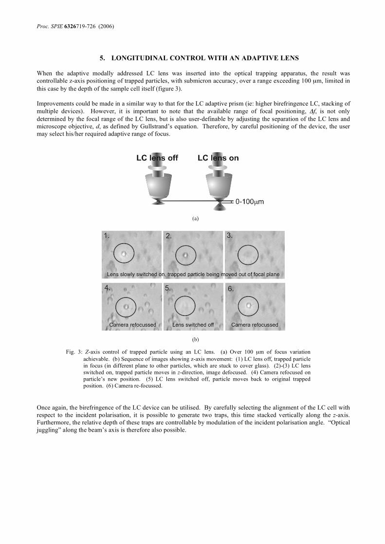
When the adaptive modally addressed LC lens was inserted into the optical trapping apparatus, the result was controllable z-axis positioning of trapped particles, with submicron accuracy, over a range exceeding 100 µm, limited in this case by the depth of the sample cell itself (figure 3). Improvements could be made in a similar way to that for the LC adaptive prism (ie: higher birefringence LC, stacking of multiple devices). However, it is important to note that the available range of focal positioning, Δf, is not only determined by the focal range of the LC lens, but is also user-definable by adjusting the separation of the LC lens and microscope objective, d, as defined by Gullstrand’s equation. Therefore, by careful positioning of the device, the user may select his/her required adaptive range of focus.
Fig. 3: Z-axis control of trapped particle using an LC lens. (a) Over 100 µm of focus variation achievable. (b) Sequence of images showing z-axis movement: (1) LC lens off, trapped particle in focus (in different plane to other particles, which are stuck to cover glass). (2)-(3) LC lens switched on, trapped particle moves in z-direction, image defocused. (4) Camera refocused on particle’s new position. (5) LC lens switched off, particle moves back to original trapped position. (6) Camera re-focussed.
Once again, the birefringence of the LC device can be utilised. By carefully selecting the alignment of the LC cell with respect to the incident polarisation, it is possible to generate two traps, this time stacked vertically along the z-axis. Furthermore, the relative depth of these traps are controllable by modulation of the incident polarisation angle. “Optical juggling” along the beam’s axis is therefore also possible.

Proc. SPIE 6326719-726 (2006)
6. COUNTER-PROPAGATING BEAMS
To illustrate the flexibility and effectiveness of these LC adaptive devices, the LC beam-steering device was added to one arm of a counter-propagating beams experiment. As the one beam is steered through a small angle, the overlap between the two beams (and the location of the optical trap) changes. The single trap contained two 2.3 µm particles, which were successfully deflected as the LC device was switched on. With an applied voltage of only 3.75V (V1 – V2). 27 µm of deflection was observed along the axes of the two beams, whilst a smaller deflection of around 2 µm was also observed in the x-y plane (figure 4). A slight mismatch in the initial parallelism of the two beams accounts for this dual movement. This effect can be exploited to the user’s advantage to select the required deflection range and resolution.
Fig. 4: Deflection of a pair of trapped particles in a counter-propagating beams optical trap (a) 2 µm of deflection in the x-y plane, and (b) 27 µm of deflection along the beams’ axes.
7. CONCLUSIONS Adaptive liquid-crystal devices have been developed, which are capable of providing three-dimensional position control of an optical trap. These devices are cheap to manufacture, simple in design and easy to implement into any existing optical trapping system. Against this, they don't have the sophistication of more complex HOT and GPC techniques, enabling simultaneous manipulation of multiple traps. In the particular trapping arrangements described above, manipulation of trapped particles are controllable using an adaptive LC prism within a circle of 20 µm diameter in the x-y plane. An adaptive modal LC lens can also be used to move the trapped particle within a range of 100 µm along the beam’s axis. In a counter-propagating beams optical trap, at least 27 µm of movement control along the beams’ axes are observed using the LC adaptive prism alone. It is important to note that these figures are subject to our particular optical arrangements, and can be easily tailored to suit the user’s requirements of range and resolution with more careful positioning of the devices and by selection of an appropriate objective lens. Further improvements in performance are also predicted through use of higher birefringence LCs and by the stacking of multiple devices.

Proc. SPIE 6326719-726 (2006)
The use of LC devices in optical trapping also provides opportunities for unique dual-trap experiments of variable separation and depth. For example, by simple modulation of the incident polarisation with an LC variable retarder, the exchange of particles between adjacent optical traps in the form of “optical juggling” has been demonstrated. LC adaptive devices impart no observable degradation in performance of existing optical trapping systems. This, combined with their ability to be easily retro-fitted to an existing set-up, means that they could be readily used to simplify many manipulation tasks and also to add new unique features of control for optical trapping.
ACKNOWLEDGEMENTS
This research is supported by the UK Engineering and Physical Sciences Research Council (EPSRC) and the European Science Foundation Eurocore-SONS programme – SPANAS.
REFERENCES
1. P.J.W. Hands, S.A. Tatarkova, A.K. Kirby and G.D. Love, "Modal liquid crystal devices in optical tweezing:
3D control and oscillating potential wells," Opt. Express, 14, 4525-4537 (2006) 2. E.R. Dufresne and D.G. Grier, "Optical tweezer arrays and optical substrates created with diffractive optics,"
Rev. Sci. Instum., 69(5), 1974-1977 (1998) 3. J. Liesener, M. Reicherter, T. Haist and H.J. Tiziani, "Multi-functional optical tweezers using computer-
generated holograms," Opt. Commun., 185, 77-82 (2000) 4. E.R. Dufresne, G.C. Spalding, M.T. Dearing, S.A. Sheets and D.G. Grier, "Computer-generated holographic
optical tweezer arrays," Rev. Sci. Instum., 72(3), 1810-1816 (2001) 5. J.E. Curtis, B.A. Koss and D.G. Grier, "Dynamic holographic optical tweezers," Opt. Commun., 207, 169-175
(2002) 6. K. Dholakia, G. Spalding and M. MacDonald, "Optical tweezers: the next generation," Physics World, 15(31),
(2002) 7. J.M.R. Fournier, M.M. Burns and J.A. Golovchenko, "Writing diffractive structures by optical trapping," in
Practical Holography IX, S.A. Benton, Proc. SPIE, 2406, 101-111 (1995) 8. J. Gluckstad and P.C. Mogensen, "Reconfigurable ternary-phase array illuminator based on the generalised
phase contrast technique," Opt. Commun., 173, 169-175 (2000) 9. P.C. Mogensen and J. Gluckstad, "Dynamic array generation and pattern formation for optical tweezers," Opt.
Commun., 175, 75-81 (2000) 10. R.L. Eriksen, P.C. Mogensen and J. Gluckstad, "Multiple-beam optical tweezers generated by the generalized
phase-contrast method," Opt. Lett., 27(4), 267-269 (2002) 11. P.J. Rodrigo, V.R. Daria and J. Gluckstad, "Real-time three-dimensional optical micromanipiulation of
multiple paticles and living cells," Opt. Lett., 29(19), 2270-2272 (2004) 12. P.J. Rodrigo, V.R. Daria and J. Gluckstad, "Dynamically reconfigurable optical lattices," Opt. Express, 13,
1384-1394 (2005) 13. M. Kawamura, M. Ye and S. Sato, "Optical trapping and manipulation system using liquid-crystal lens with
focussing and deflection properties," Jpn. J. Appl. Phys., 44(8), 6098-6100 (2005) 14. A. Ashkin and J.M. Dziedzic, "Observation of radiation-pressure trapping of particles by alternating light
beams," Phys. Rev. Lett., 54(12), 1245-1248 (1984) 15. S.A. Tatarkova, A.E. Carruthers and K. Dholakia, "One-dimensional optically bound arrays of microscopic
particles," Phys. Rev. Lett., 89, 283901 (2002) 16. P.J. Rodrigo, V.R. Daria and J. Gluckstad, "Four-dimensional optical manipulation of colloidal particles,"
Appl. Phys. Lett., 86(074103), (2005) 17. G.D. Love, J.V. Major and A. Purvis, "Liquid crystal prisms for tip-tilt adaptive optics," Opt. Lett., 19(15),
1170-1172 (1994)

Proc. SPIE 6326719-726 (2006)
18. V. Laude and C. Dirson, "Liquid crystal active lens: application to image resolution enhancement," Opt. Commun., 163, 72-78 (1999)
19. M.A.A. Neil and R. Juskaitis, "Adaptive aberration correction in a two-photon microscope," J. Microsc., 200, 105-108 (2000)
20. M. Hain, R. Glockner, S. Bhattacharya, D. Dias, S. Stankovic and T. Tschudi, "Fast switching liquid crystal lenses for a dual focus digital versatile disc pickup," Opt. Commun., 188, 291-299 (2001)
21. A.F. Naumov, M.Y. Loktev, I.R. Guralnik and G.V. Vdovin, "Liquid-crystal adaptive lenses with modal control," Opt. Lett., 23(13), 992-994 (1998)
22. A.F. Naumov and G.D. Love, "Control optimisation of spherical modal liquid crystal lenses," Opt. Express, 4(9), 344-352 (1999)
23. P.J.W. Hands, G.D. Love and A.K. Kirby, "Adaptive modally addressed liquid crystal lenses," in Liquid Crystals VIII, I.-C. Khoo, Proc. SPIE, 5188, 136-143 (2004)
24. A.K. Kirby, P.J.W. Hands and G.D. Love, "Optical design of liquid crystal lenses: off-axis modelling," in Current Developments in Lens Design and Optical Engineering VI, P.Z. Mouroulis, W.J. Smith and R.B. Johnson, Proc. SPIE, 5874, 07 (2005)