optimal fir filters for dtmf applications
TRANSCRIPT

Optimal FIR Filters for DTMF ApplicationsPavel Zahradnik and BorisSimak
Telecommunication Engineering DepartmentCzech Technical University in Prague
Prague, Czech Republic{zahradni, simak}@fel.cvut.cz
Miroslav VlcekApplied Mathematics Department
Czech Technical University in PraguePrague, Czech Republic
Abstract—A fast and robust analytical procedure for thedesign of high performance digital optimal band-pass finiteimpulse response filters for dual-tone multi-frequency applica-tions is introduced. The filters exhibit equiripple behavior ofthe frequency response. The approximating function is basedon Zolotarev polynomials. The presented closed form solutionprovides formulas for the filter degree and for the impulseresponse coefficients. Several examples are presented.
Keywords-FIR filter; narrow band filter; dual-tone multi-frequency; iso-extremal approximation.
I. I NTRODUCTION
There are two basic tasks in the processing of dual-tonemulti-frequency (DTMF) signals, namely the detection ofDTMF frequencies and the removal of the DTMF frequenciesin a broad band signal. The DTMF frequencies form twogroups with four frequencies each. The lower group consistsof frequencies 697, 770, 852 and 941 Hz while the highergroup comprises sinusoids of 1209, 1336, 1477 and 1633Hz. For the processing of DTMF signals, the infinite impulseresponse (IIR) filters are usually applied because of theirlower number of coefficients. The IIR filters are usually partof the famous Goertzel procedure [1]. In the removal ofDTMF frequencies in a broad band signal, the IIR filtersproduce substantial distortions of the output signal whichappear near its flat region due to the group delay variation.This behavior is especially apparent, if pulse like componentsare present in the signal as demonstrated in [2]. In orderto minimize these distortions in the processing of DTMFsignals we propose the application of finite impulse response(FIR) filters which inherit a constant group delay. In orderto maximize the discrimination of the DTMF sinusoids, theselective bands of the FIR filters should be as narrow aspossible. In this paper we are focused upon the design ofnarrow optimal equiripple (ER) band-pass (BP) FIR filters forthe DTMF decoding. They are optimal in terms of the shortestpossible filter length related to the frequency specification.Note that the proposed filter design is based on formulas, i.e.no numerical procedures are involved. The presented closedform solution includes the degree equation and formulas forthe robust evaluation of the impulse response coefficients ofthe filter.
II. T ERMINOLOGY
We assume a general FIR filter of type I represented byits impulse responseh(k) with odd length ofN = 2n + 1coefficients and with even symmetry (1). In our further con-siderations we use thea-vectora(k), which is related to theimpulse responseh(k)
a(0) = h(n) , a(k) = 2h(n+ k) = 2h(n− k) , k = 1 ... n .(1)
Further, we introduce an auxiliary real variablew
w =1
2(z + z−1)|
z=ejωT = cos(ωT ) = cos
(
2πf
fs
)
, (2)
wherefs is the sampling frequency. The transfer function ofthe filter is
H(z) =2n∑
k=0
h(k) z−k
= z−n
[
h(n) + 2
n∑
k=1
h(n± k)1
2
(
zk + z−k)
]
= z−n
n∑
k=0
a(k)Tk(w) = z−nQ(w) (3)
whereTk(w) = cos(k arccos(w)) is Chebyshev polynomial ofthe first kind andQ(w) is the real valued zero phase transferfunction which we express using thea-vector in form of theexpansion of Chebyshev polynomials
Q(w) =
n∑
k=0
a(k)Tk(w) . (4)
The zero phase transfer function of an ER BP FIR filter is
Q(w) =Zp,q(w, κ) + 1
ym + 1, (5)
where Zp,q(w, κ) represents the Zolotarev polynomial [8].For illustration, the shape of a Zolotarev polynomial is shownin Fig. 1 and the corresponding frequency response is shownin Fig. 2.
163Copyright (c) IARIA, 2013. ISBN: 978-1-61208-245-5
ICN 2013 : The Twelfth International Conference on Networks

−1 −0.8 −0.6 −0.4 −0.2 0 0.2 0.4 0.6 0.8 1
0
5
10
15
20
Z12,6
(w
,0.7
9023439)
w
w1 w2w0
y0
Fig. 1. Zolotarev polynomialZ12,6(w, 0.79023439).
0 0.1 0.2 0.3 0.4 0.5 0.6 0.7 0.8 0.9 1−60
−50
−40
−30
−20
−10
0
20lo
g|H
(ejωT
)|[
dB
]
ωT/π
as [dB]∆ωT/π
ω0Tπ
Fig. 2. Amplitude frequency response20 log |H(ejωT )| [dB] correspondingto the Zolotarev polynomial from Fig. 1.
III. O PTIMAL BAND-PASS FIR FILTER
An optimal ER BP FIR filter (Fig. 2) is specified by thepass band frequencyω0T (or f0 = ω0Tfs/2π), width ofthe pass band∆ωT (or ∆f = ∆ωTfs/2π), attenuation inthe stop-bandsas[dB] and by the sampling frequencyfs. Anapproximation of the frequency response of a filter is based onthe generating function. The generating function of an ER BPFIR filter is the Zolotarev polynomialZp,q(w, κ) which ap-proximates a constant value in equiripple Chebyshev sense intwo disjoint intervals〈−1, w1〉 and〈w2, 1〉 as shown in Fig. 1.The main lobe with the maximal valuey0 = Zp,q(w0, κ) islocated inside the interval(w1, w2). The notationZp,q(w, κ)emphasizes the fact that the integer valuep counts the numberof zeros right from the maximumw0 and the integer valueqcorresponds to the number of zeros left from the maximumw0. The real value0 ≤ κ ≤ 1 is in fact the Jacobi ellipticalmodulus. It affects the maximum valuey0 and the widthw2 − w1 of the main lobe (Fig. 1). For increasingκ the
valuey0 increases and the main lobe broadens. The Zolotarevpolynomial is usually expressed in terms of Jacobi ellipticfunctions [6]-[8]
Zp,q(w, κ) =(−1)p
2(6)
×
H(u−p
nK(κ))
H(u+p
nK(κ))
n
+
H(u+p
nK(κ))
H(u−p
nK(κ))
n
.
The factor(−1)p/2 appears in (6) as the Zolotarev polynomialalternates(p+ 1)−times in the interval(w2, 1). The variableu is expressed by the incomplete elliptical integral of the firstkind F (x|κ), namely
u =F
sn( p
nK(κ)|κ
)
√
√
√
√
1 + w
w + 2 sn2( p
nK(κ)|κ
)
− 1|κ
.
(7)The functionH (u± (p/n) K(κ)) is the Jacobi Eta function,sn(u|κ), cn(u|κ), dn(u|κ) are Jacobi elliptic functions andK(κ) is the quarter-period given by the complete elliptic inte-gral of the first kind. The degree of the Zolotarev polynomialisn = p+q. A comprehensive treatise of Zolotarev polynomialswas published in [8]. It includes the analytical solution ofthecoefficients of Zolotarev polynomials, the algebraic evaluationof the Jacobi Zeta function Z( p
nK(κ)|κ) and of the elliptic
integral of the third kindΠ(σm, p
nK(κ)|κ). The positionw0
of the maximum valuey0 = Zp,q(w0, κ) is
w0 = w1 + 2sn( p
nK(κ)|κ
)
cn( p
nK(κ)|κ
)
dn( p
nK(κ)|κ
) Z( p
nK(κ)|κ
)
(8)where the edges of the main lobe are
w1 = 1− 2 sn2( p
nK(κ)|κ
)
(9)
w2 = 2 sn2( q
nK(κ)|κ
)
− 1 . (10)
The relation for the maximum valuey0
y0 = cosh 2n(
σmZ(p
nK(κ)|κ)−Π(σm,
p
nK(κ)|κ)
)
(11)
is useful in the normalization of Zolotarev polynomials. Thedegree of the Zolotarev polynomialZp,q(w, κ) is expressed bythe degree formula
n ≥ln(y0 +
√
y20− 1)
2σmZ( pn
K(κ)|κ)− 2Π(σm, p
nK(κ)|κ)
. (12)
The auxiliary valueσm in (11), (12) is given by the formula
σm = F
(
arcsin
(
1
κ sn(
p
nK(κ)|κ
)
√
w0 − ws
w0 + 1
)
|κ
)
(13)
= F
arcsin
√
cos
(
2πf0fs
)
− cos
[
2π
fs
(
f0 +∆f
2
)]
κ sn( p
nK(κ)|κ
)
√
1 + cos
(
2πf0fs
)
|κ
.
164Copyright (c) IARIA, 2013. ISBN: 978-1-61208-245-5
ICN 2013 : The Twelfth International Conference on Networks

The Zolotarev polynomialZp,q(w, κ) satisfies the differentialequation
(1− w2)(w − w1)(w − w2)
(
dZp,q(w, κ)
dw
)2
(14)
= n2(
1− Z2
p,q(w, κ))
(w − w0)2 .
Based on the differential equation (14) we have developed analgorithm for the evaluation of thea-vector and of the impulseresponseh(k) corresponding to the Zolotarev polynomialZp,q(w, κ) in form of its expansion into Chebyshev polynomi-als (4). This algorithm is summarized in Table I. There are twogoals in the filter design. The first one is to obtain the minimalfilter length ofN coefficients satisfying the filter specification.The second one is to evaluate its impulse responseh(k).In the standard design of an ER BP FIR filter, which isrepresented by the numerical Parks-McClellan procedure (e.g.the functionfirpm in Matlab), the exact filter length is notavailable because of no approximating function. Consequently,the filter length is not the result of the design, it is in fact aninput argument in the Parks-McClellan procedure. The filterlength is either estimated or successively adjusted in order tomeet the filter specification, or it is obtained from empiricalapproximating formulas. Moreover, a successful design is notguaranteed in the Parks-McClellan procedure. The alternativedesign approach that we use here is based on the analyticaldesign which we have developed for ER notch FIR filters andintroduced in [3]. The available pass band frequencies whichwe denotefQ are quantized because there is always an integernumber of ripples (Fig. 2). That is why we additionally tunethe actual pass band frequencyfQ of the initial filter to thespecified valuef0. This tuning consists in multiplying thea-vector of the initial filter by a transformation matrix, resultingin thea-vector of the tuned filter (16) which exactly meets thespecified pass band frequency. For the tuning, we present anefficient algebraic procedure which is a simplified version ofthat one introduced in [4]. The tuning procedure results in thezero phase transfer function of the tuned filter, which is
Qt(w) =
n∑
k=0
a(k)Tk(λw±λ′
) =
n∑
k=0
a(k)
k∑
m=0
αk(m)Tm(w).
(15)
Based on (15), thea-vectorat(k) of the tuned filter and thea-vector a(k) of the initial filter are related by a triangulartransformation matrixA
at(k) = [at(0) at(1) · · · at(n)] = [a(0) a(1) · · · a(n)]×
×
α0(0) 0 0 0 · · · 0α1(0) α1(1) 0 0 · · · 0α2(0) α2(1) α2(2) 0 · · · 0α3(0) α3(1) α3(2) α3(3) · · · 0...
...αn(0) αn(1) αn(2) αn(3) · · · αn(n)
= a(k)A .
(16)
A fast algorithm for the evaluation of the coefficientsαk(m)is summarized in Tab. II. The presented tuning of the passband frequency preserves the attenuationas[dB] in the stopbands.
IV. D ESIGN OF THEOPTIMAL BAND-PASS FIR FILTER
Let us specify the optimal ER BP FIR filter by the pass bandfrequencyf0[Hz], width of the pass band∆f [Hz], samplingfrequencyfs[Hz] and by the attenuation in the stop bandsas[dB]. The design procedure reads as follows:Calculate the Jacobi elliptic modulusκ
κ =
√
1−1
tan2(ϕ1) tan2(ϕ2)
(17)
for the auxiliary valuesϕ1 andϕ2
ϕ1 =π
fs
(
f0 +∆f
2
)
, ϕ2 =π
fs
(
fs2
− f0 +∆f
2
)
.
(18)Calculate the rational valuespn and q
n
p
n=
F (ϕ1, κ)
K(κ),
q
n=
F (ϕ2, κ)
K(κ), (19)
where K(κ) is a complete elliptic integral of the first kind,which here represents the elliptic quarter-period. Determinethe valuey0
y0 =2
100.05as[dB]. (20)
Calculate the auxiliary valueσm (13).Calculate and round up the valuen (12) which represents thedegreen = p + q of the Zolotarev polynomialZp,q(w, κ).Calculate the integer indicesp and q of the ZolotarevpolynomialZp,q(w, κ)
p =
x
y
nF (ϕ1, κ)
K(κ)
x
y
, q =
x
y
nF (ϕ2, κ)
K(κ)
x
y
. (21)
The arrow brackets in (21) stand for rounding. For valuesp,q (21), κ (17) andy0 (20) evaluate thea-vectora(k) and therelated impulse responseh(k) of the filter using the algebraicalprocedure summarized in Tab. I. Check the actual pass bandfrequencyfQ of the initial BP FIR filter
fQ =fs2π
arccos
[
1− 2 sn2( p
nK(κ), κ
)
(22)
+2sn( p
nK(κ), κ
)
cn( p
nK(κ), κ
)
dn( p
nK(κ), κ
) Z( p
nK(κ), κ
)
]
.
Because of the inherent quantization of the available passband frequenciesfQ mentioned above, the actual pass bandfrequencyfQ usually slightly differs from the specified passband frequencyf0. That is why we tune the quantized passband frequencyfQ of the initial filter to the specified valuef0using (16) and Tab. II. In our calculations, the Jacobi ellipticZeta function Z(x, κ) in (8), (11), (12) and the incompleteelliptic integral of the first kindF (x, κ) in (13) are evaluated
165Copyright (c) IARIA, 2013. ISBN: 978-1-61208-245-5
ICN 2013 : The Twelfth International Conference on Networks

given p, q, κ, y0
initialization n = p+ q , w1 = 1− 2 sn2(
p
nK(κ), κ
)
, w2 = 2 sn2(
q
nK(κ), κ
)
− 1 , wa =w1 + w2
2
wm = w1 + 2
sn(
p
nK(κ), κ
)
cn(
p
nK(κ), κ
)
dn(
p
nK(κ), κ
) Z(
p
nK(κ), κ
)
α(n) = 1 , α(n + 1) = α(n+ 2) = α(n+ 3) = α(n + 4) = α(n+ 5) = 0body(for m = n+ 2 to 3)
8c(1) = n2 − (m+ 3)2 , 4c(2) = (2m + 5)(m + 2)(wm −wa) + 3wm[n2 − (m + 2)2]
2c(3) =3
4[n2 − (m + 1)2] + 3wm[n2wm − (m+ 1)2wa]− (m+ 1)(m + 2)(w1w2 −wmwa)
c(4) =3
2(n2 −m2) +m2(wm − wa) +wm(n2w2
m −m2w1w2)
2c(5) =3
4[n2 − (m − 1)2] + 3wm[n2wm − (m− 1)2wa]− (m− 1)(m − 2)(w1w2 −wmwa)
4c(6) = (2m − 5)(m − 2)(wm − wa) + 3wm[n2 − (m− 2)2] , 8c(7) = n2 − (m− 3)2
α(m − 3) =1
c(7)
6∑
µ=1
c(µ)α(m + 4− µ)
(end loop on m)
normalization s(n) =α(0)
2+
n∑
m=1
α(m)
a-vector a(0) = (−1)pα(0)
2s(n), (for m = 1 to n) , a(m) = (−1)p
α(m)
s(n), (end loop on m)
impulse response h(n) =a(0) + 1y0 + 1 , (for m = 1 to n) , h(n±m) =
a(m)
2(y0 + 1), (end loop on m)
TABLE IFAST ALGORITHM FOR EVALUATING THE a-VECTORa(k) AND THE IMPULSE RESPONSEh(k).
given fQ, f0, fs, k
initialization if fQ < f0 : λ =
cos
(
2πfQ
fs
)
− 1
cos
(
2πf0
fs
)
− 1, s = 1, else :λ =
cos
(
2πfQ
fs
)
+ 1
cos
(
2πf0
fs
)
+ 1, s = −1
λ′= 1− λ , αk(k + 1) = αk(k + 2) = αk(k + 3) = 0 , αk(k) = λk
body(for µ = −3 ... k − 4 )
αk(k − µ− 4) ={
−2s
[
(µ + 3)(2k − µ− 3) − λ′
λ(k − µ− 3)(2k − 2µ− 7)
]
αk(k − µ− 3)
+2 λ′
λ(k − µ− 2) αk(k − µ − 2)
+2s
[
(µ + 1)(2k − µ− 1)− λ′
λ(k − µ− 1)(2k − 2µ− 1)
]
αk(k − µ− 1)
+µ(2k − µ) αk(k − µ)} / (µ+ 4)(2k − µ− 4)
(end loop onµ)
TABLE IIFAST ALGORITHM FOR EVALUATING THE COEFFICIENTSαk(m) OF TRANSFORMATIONMATRIX A.
166Copyright (c) IARIA, 2013. ISBN: 978-1-61208-245-5
ICN 2013 : The Twelfth International Conference on Networks
by the arithmetic-geometric mean [7]. The Jacobi ellipticintegral of the third kindΠ(x, y, κ) in (12) is evaluated bya fast procedure proposed in [3].
0 500 1000 1500 2000 2500 3000 3500 4000
−80
−70
−60
−50
−40
−30
−20
−10
0
f
20lo
g|H
(ej2πf/fs)|
[dB
]
0 500 1000 1500 2000 2500 3000 3500 4000
−120
−100
−80
−60
−40
−20
0
f
20lo
g|H
(ej2πf/fs)|
[dB
]
0 500 1000 1500 2000 2500 3000 3500 4000
−160
−140
−120
−100
−80
−60
−40
−20
0
f
20lo
g|H
(ej2πf/fs)|
[dB
]
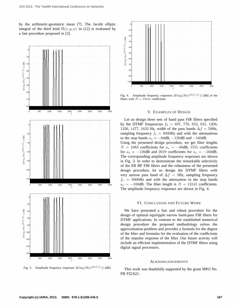
Fig. 3. Amplitude frequency responses20 log |H(ej2πf/fs)| [dB].
0 500 1000 1500 2000 2500 3000 3500 4000
−100
−90
−80
−70
−60
−50
−40
−30
−20
−10
0
f
20lo
g|H
(ej2πf/fs)|
[dB
]
Fig. 4. Amplitude frequency responses20 log |H(ej2πf/fs)| [dB] of thefilters with N = 13141 coefficients.
V. EXAMPLES OF DESIGN
Let us design three sets of band pass FIR filters specifiedby the DTMF frequenciesf0 = 697, 770, 852, 941, 1209,1336, 1477, 1633 Hz, width of the pass bands∆f = 50Hz,sampling frequencyfs = 8000Hz and with the attenuationsin the stop bandsas = −80dB, −120dB and−160dB.Using the presented design procedure, we get filter lengthsN = 1083 coefficients foras = −80dB, 1551 coefficientsfor as = −120dB and2019 coefficients foras = −160dB.The corresponding amplitude frequency responses are shownin Fig. 3. In order to demonstrate the remarkable selectivityof the ER BP FIR filters and the robustness of the presenteddesign procedure, let us design the DTMF filters withvery narrow pass band of∆f = 5Hz, sampling frequencyfs = 8000Hz and with the attenuation in the stop bandsas = −100dB. The filter length isN = 13141 coefficients.The amplitude frequency responses are shown in Fig. 4.
VI. CONCLUSION AND FUTURE WORK
We have presented a fast and robust procedure for thedesign of optimal equiripple narrow band-pass FIR filters forDTMF applications. In contrast to the established numericaldesign procedure the proposed methodology solves theapproximation problem and provides a formula for the degreeof the filter and formulas for the evaluation of the coefficientsof the impulse response of the filter. Our future activity willinclude an efficient implementation of the DTMF filters usingdigital signal processors.
ACKNOWLEDGEMENTS
This work was thankfully supported by the grant MPO No.FR-TI2/621.
167Copyright (c) IARIA, 2013. ISBN: 978-1-61208-245-5
ICN 2013 : The Twelfth International Conference on Networks

REFERENCES
[1] G. Goertzel, An Algorithm for the evaluation of finite trigonometricSeries,Amer. Math. Monthly. Vol. 65, January 1958, pp. 34-35.
[2] M. Vlcek, P. Zahradnik, Digital Multiple Notch FiltersPerformance,Proceedings of the 15th European Conference on Circuit Theory andDesign ECCTD’01. Helsinky, August 2001, pp. 49-52.
[3] P. Zahradnik, M. Vlcek, Fast Analytical Design Algorithms for FIR NotchFilters, IEEE Transactions on Circuits and Systems. March 2004 , Vol.51, No. 3, pp. 608 - 623.
[4] P. Zahradnik, M. Vlcek, An Analytical Procedure for Critical FrequencyTuning of FIR Filters. IEEE Transactions on Circuits and Systems II.January 2006, Vol. 53, No. 1, pp. 72-76.
[5] N. I. Achieser, Uber einige Funktionen, die in gegebenen Intervallen amwenigsten von Null abweichen,Bull. de la Soc. Phys. Math. de Kazan,Vol. 3, pp. 1 - 69, 1928.
[6] D. F. LawdenElliptic Functions and ApplicationsSpringer-Verlag, NewYork Inc., 1989.
[7] M. Abramowitz, I. Stegun,Handbook of Mathematical Function, DoverPublication, New York Inc., 1972.
[8] M. Vlcek, R. Unbehauen, Zolotarev Polynomials and Optimal FIR Filters,IEEE Transactions on Signal Processing, Vol. 47, No. 3, pp. 717-730,March 1999.
168Copyright (c) IARIA, 2013. ISBN: 978-1-61208-245-5
ICN 2013 : The Twelfth International Conference on Networks