optimal parameters of the iq imbalance correction adaptive ...€¦ · (ber) and rx sensitivity in...
TRANSCRIPT
Abstract—In phase (I) and quadrature (Q) complex signal
representation (I+jQ) of the modulated signal is widely used in
RF systems. Ideally, I and Q signals have equal amplitude while
Q is 90o phase shifted relative to I in the case of SSB (single-
sideband) modulations. Having quadrature signaling provides
many advantages such as higher RF spectrum efficiency (more
bits/Hz), lower data converters (ADCs/DACs) sampling rate for
the same data throughput, computational power of the base band
modem is relaxed, all making low power transceiver
implementations possible. However, any mismatch of gain or
phase between I and Q (IQ imbalance) will degrade transceiver
performance. Error vector magnitude (EVM), bit error rate
(BER) and RX sensitivity in homodyne radios are among the
most critical parameters affected. There are multiple sources of
IQ imbalance. RF mixers can have different gain for I and Q
paths, and the gain can also be frequency dependent. PLL which
is responsible to generate quadrature LO produces nonequal I
and Q signals in terms of phase shift. Even base band modules
such as low pass filters or gain stages can contribute. The most
difficult to estimate during the system design phase is in fact IQ
cross talk happening both on the PCB and inside the RF IC. This
paper provides insight into an adaptive filtering method for the
correction of the I/Q imbalance in the receive chain. The image
rejection is evaluated using 64-QAM and 16-QAM test signals
for different adaptive filter designs. The efficiency of the
algorithm is inspected in the parameter space consisting of the
adaptation step-size and the order of the adaptive filter.
Simulation results show that zero order filter and reasonably low
value of step-size provide optimum filtering for the above
mentioned test cases. Constellation diagrams of the simulated
received and adaptively filtered signals illustrate the importance
of the adaptive filter key parameters setting.
Index Terms—Adaptive filtering; I/Q imbalance; RF
communications; QAM; Quadrature signal processing.
I. INTRODUCTION
The computational power of modern processors facilitates
the analysis of vast volumes of information in real‐time. Real
world signals are continuous in amplitude and time, and need
to be represented in digital form by discretization in time and
quntization in amplitude so that digital computer can process
them. Digital signal processing can be found in many different
Miljan Petrović – Faculty of Electronic Engineering, University of Niš,
Aleksandra Medvedeva 14, 18000 Niš, Serbia (e-mail:
Miljana Milić – Faculty of Electronic Engineering, University of Niš,
Aleksandra Medvedeva 14, 18000 Niš, Serbia (e-mail:
Srdjan Milenković – Faculty of Electronic Engineering, University of Niš,
Aleksandra Medvedeva 14, 18000 Niš, Serbia (e-mail:
applications. DSP algorithms are predictable and repeatable
for the same given inputs stream. This further gives the
advantage of easy simulation and short design time [1].
In order to improve the DSP power, complex number
mathematics can be applied, offering methods that cannot be
realized with real number mathematics. Complex DSP is more
abstract and theoretical than the real DSP. Nevertheless,
complex DSP is more powerful and comprehensive. Methods
and transformations over the complex numbers, such as
complex modulations, filtering, mixing, z-transform, speech
analysis and synthesis, adaptive complex processing, complex
Fourier transforms etc., are the essential parts of the complex
DSP. Many wireless high-speed telecommunication standards
(Wi-Fi, 3G, 4G and soon coming 5G, for example) require
complex DSP methods. Complex signals are very common in
telecommunications and the corresponding complex methods
became inevitable [2].
I/Q (In phase / Quadrature) signals are often used in RF
applications. They form the basis of the complex RF signal
modulation, demodulation, and complex signal analysis. The
In-phase signal is referred to as I, and the signal Q has all
frequency components shifted by 90o in the case of SSB
(single-sideband) modulations [3]. The amplitude and the
phase of the sum of the quadrature signals are functions of the
values of I and Q. Therefore, one can create modulated RF
signals by varying I and Q- signals over time. In other words,
using this technique, one does not need to directly vary the
phase of an RF carrier (LO). Complex quadrature signal
processing is a crucial concept in radar systems, coherent
processing, antenna beamforming applications, mobile
communications, etc [4].
Some advantages of I/Q signal representations are as
follows: for the same signal bandwidth, one can use half the
sampling rate of the standard real-signal sampling, which
further provides low power implementation; calculation of
FFT (Fast Fourier Transform) is more computationally
efficient; instantaneous amplitude and phase can be accessed
via I and Q signals.
However, ideal phase shift and consequently, ideal I/Q
signal representation is more difficult to achieve in the real
radio system due to mismatches in the analog and RF receiver
blocks. The purpose of this paper is to examine a method for
I/Q imbalance correction based on adaptive digital filtering of
the complex symbol sequence. First, I/Q structure of the
receiver is described. Further, I/Q imbalance problem is
presented and some developed solutions are reviewed.
Finally, the adaptive correction filter is described and
Optimal Parameters of the IQ Imbalance
Correction Algorithm Based on Adaptive Filter
Miljan Petrović, Miljana Milić, Srđan Milenković,University of Niš
Proceedings of 4th International Conference on Electrical, Electronics and Computing Engineering, IcETRAN 2017, Kladovo, Serbia, June 05-08, ISBN 978-86-7466-692-0
pp. ELI1.5.1-5
designed for 64-QAM and 16-QAM signals. The aim of the
paper is to find patterns in the procedure of estimating the
optimal step-size and filter order. Conclusions about
effects of these parameters on the I/Q imbalance correction
algorithm are given at the end.
II. I/Q RECEIVER DESIGN
A. Receiver Structure
The structure of an I/Q RF receiver is given in Fig. 1.
the signal coming from antenna point and amplified by low
noise amplifier (LNA) is mixed with the
signal generated by the PLL. This shifts the signal
back to baseband frequency. The two outputs are passed
through the identical anti alias/channel select
and further sampled and quantized by A/D converters. Finally,
we get the in phase and quadrature signals
processing. It should be noted that for a correct functioning of
the adaptive algorithm (that will be described
section), a symbol detector in the digital domain should be
implemented between the receiver structure
adaptive filter. Often, as shown in Fig. 1, programmable
stages are placed between the blocks in order to fulfill the
dynamic range specifications of the consequent block.
Fig. 1. Schematic of the RF receiver structure.
B. I/Q Imbalance Problem
Ideal I and Q signals are 90o phase
identical amplitude in the case of SSB modulations
means that the spectrum of the signal I+jQ only consists of
positive frequency components (in the baseband)
mismatches of electronic components often lead to problem
known as the I/Q imbalance. In general, it is difficult to
achieve symmetry in analog circuitry.
signals are not exactly 90o shifted, frequency responses of the
low pass filters are slightly different, layout desig
different path delays for I and Q signals, capacitors
mismatches in filters and A/D converters can induce
interference, etc [5]. It is known that wideband I and Q signals
have frequency dependent imbalance, whereas
signals have frequency independent imbalance
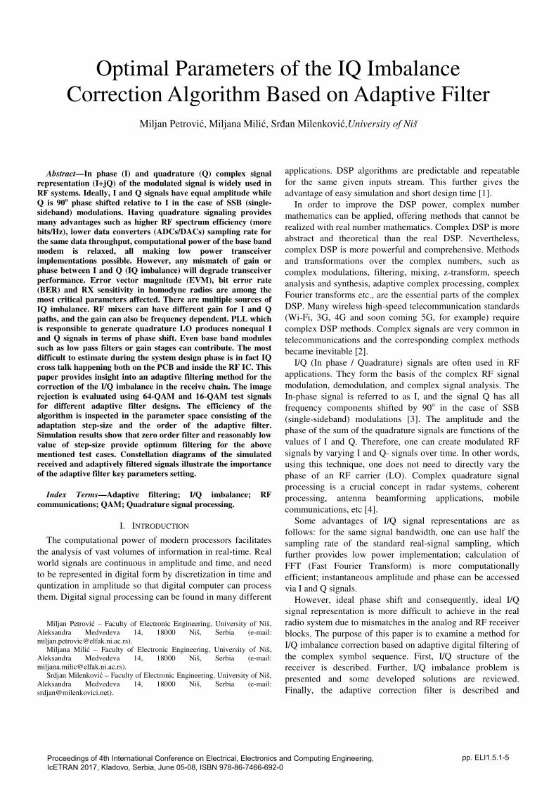
I/Q imbalance is illustrated in Fig. 2
receiver. The wanted signal spectrum is centered
frequency f0. Ideally, there should be no signal components
the range f<0. However, due to the I/Q imbalance,
QAM signals. The aim of the
the procedure of estimating the
Conclusions about the
effects of these parameters on the I/Q imbalance correction
ESIGN
The structure of an I/Q RF receiver is given in Fig. 1. First,
coming from antenna point and amplified by low
is mixed with the quadrature carrier
This shifts the signal from RF
The two outputs are passed
anti alias/channel select low pass filters,
A/D converters. Finally,
s ready for further
for a correct functioning of
(that will be described in the next
a symbol detector in the digital domain should be
ructure of Fig. 1 and the
programmable gain
in order to fulfill the
dynamic range specifications of the consequent block.
shifted and have
in the case of SSB modulations, which
means that the spectrum of the signal I+jQ only consists of
(in the baseband). However,
often lead to problem
In general, it is difficult to
achieve symmetry in analog circuitry. Therefore, carrier
shifted, frequency responses of the
low pass filters are slightly different, layout design introduces
different path delays for I and Q signals, capacitors
mismatches in filters and A/D converters can induce
that wideband I and Q signals
whereas narrowband
independent imbalance.
assuming low IF
centered around the
signal components in
. However, due to the I/Q imbalance, a signal
image is present. In zero IF receivers,
that IQ imbalance image is inside the wanted signal frequency
range and as such cannot be filtered at all. Hence
sophisticated algorithm for IQ imbalance
implemented.
Fig. 2. Illustration of the spectrum of an imbalanced I/Q signal.
C. Solutions
Since I/Q imbalance is a very common problem in
telecommunications, many techniques for reducing its effects
have been derived [6]. Here is
popular ones.
First, there is the off-line adjustment
method uses Gram-Schmidt procedure. Although it provides
good results, it is constrained by the fact
time algorithm and that it can only
frequency independent mismatches, i.e. narrow band I and Q
signals.
Another solution is to develop the analog RF receiver with
only one branch (only I output), and then generate the
quadrature signal in the digital domain
valid for SSB modulations, and
Hilbert transformer. Since a
approximation of the Hilbert transformer usually needs a high
filter order, this method leads to
delay and power consumption, and
The most popular I/Q imbalance correction method is the
application of adaptive filters.
covered by adaptive filters, since they can be used in several
classes of problems: identification and inverse
signal prediction, interference and noise cancellation
the case of the I/Q imbalance, noise cancellation structure is
used. However, certain modifications in the filter structure
and/or in the adaptive algorithm are needed to
specific problem. For example,
filter is derived filtering both
primary input. Standard structure only filte
input. An adaptive filter presented in
results in complex baseband I/Q imbalance correction.
III. ADAPTIVE I/Q IMBALANCE
A. Adaptive Algorithm
The adaptive filter evaluated in this paper is
more details in [10]. The filter
complex sequence I+jQ derived from
signal detection. Each sample represents one received s
In zero IF receivers, f0 = DC, which means
that IQ imbalance image is inside the wanted signal frequency
range and as such cannot be filtered at all. Hence a
imbalance cancellation must be
Illustration of the spectrum of an imbalanced I/Q signal.
a very common problem in
telecommunications, many techniques for reducing its effects
is a short review of the most
djustment presented in [7]. The
Schmidt procedure. Although it provides
good results, it is constrained by the facts that it is not a real
only be applied to signals with
frequency independent mismatches, i.e. narrow band I and Q
solution is to develop the analog RF receiver with
only one branch (only I output), and then generate the
quadrature signal in the digital domain [8]. This method is
valid for SSB modulations, and it incorporates a digital
Hilbert transformer. Since a high-quality digital filter
Hilbert transformer usually needs a high
leads to disadvantages such are high
and low processing speed [9].
Q imbalance correction method is the
application of adaptive filters. A wide range of problems is
covered by adaptive filters, since they can be used in several
identification and inverse modeling,
signal prediction, interference and noise cancellation [1]. In
I/Q imbalance, noise cancellation structure is
used. However, certain modifications in the filter structure
and/or in the adaptive algorithm are needed to address the
For example, in [9] a complex adaptive
both the reference input and the
tandard structure only filters the reference
n adaptive filter presented in [10], provides excellent
mplex baseband I/Q imbalance correction.
MBALANCE CANCELLATION
The adaptive filter evaluated in this paper is described in
. The filter’s primary input is the symbol
derived from I and Q channels after
signal detection. Each sample represents one received symbol.
The schematic of the filter is given in Fig. 3.
Fig. 3. Schematic of the adaptive filter for compensating I/Q imbalance.
The reference input of the filter is the complex
the primary input signal. The reference signal is filtered
through adaptive filter with coefficients w, and then added to
the primary input, thus forming the filter output. This can be
mathematically presented together with the coefficients
update expression as:
2
1
( ) ( ) ( ( )* ( ))m
m m
y n x n x n w n
w w yµ+
= +
= − ⋅
where x denotes the primary input, y the filter output,
set of complex coefficients in the mth
iteration, and
time index. This algorithm ensures that the
expectation E[y2] converges to zero [10]
consists of complex symbols, the algorithm tends to rearrange
them in the constellation diagram so that they are
symmetrically ordered around the point 0+j0
moves the symbols towards the reference points.
B. Setting Step-Size and Filter Order
After selecting the right adaptive algorithm, the next step in
I/Q imbalance correction is to define the adaptive filter’s
parameters. Two parameters are necessary
step-size μ, and the filter order N. Effects of these parameters
on the filter performance greatly depend on the specific
application. Here, the parameter space is discussed
context of I/Q imbalance correction. The errors of received
and filtered signals are evaluated in many points in the
parameter space for two types of complex modulations: 64
QAM and 16-QAM.
1) 64-QAM Case
Each sample of the received signal represents a complex
symbol, which is, due to mismatches, at some distance
(Euclidean) from the reference symbol point in the
constellation diagram. When the adaptive algorithm
converges, one should expect these distances to be lower. The
mean value of all distances in the 3500 samples long signal
(which are randomly generated symbols) is chosen a
function. This function is evaluated for the filter orders from 0
to 4, and step-sizes in the range from 10−6
to 10
are given in Fig. 4.
IQ imbalance in the received signal is simulated as changes
in amplitude and phase of generated symbols. Amplitude error
is set to 2dB and phase error to 10o.
It can be seen that filters with lower order
The schematic of the filter is given in Fig. 3.
Schematic of the adaptive filter for compensating I/Q imbalance.
The reference input of the filter is the complex conjugate of
. The reference signal is filtered
, and then added to
the primary input, thus forming the filter output. This can be
mathematically presented together with the coefficients
( ) ( ) ( ( )* ( ))m
y n x n x n w n (1)
the filter output, wm is the
iteration, and n is the
time index. This algorithm ensures that the mathematical
[10]. Since the input
consists of complex symbols, the algorithm tends to rearrange
them in the constellation diagram so that they are
0+j0. Implicitly, this
symbols towards the reference points.
the right adaptive algorithm, the next step in
I/Q imbalance correction is to define the adaptive filter’s
to set: adaptation
. Effects of these parameters
depend on the specific
is discussed in the
. The errors of received
gnals are evaluated in many points in the
of complex modulations: 64-
Each sample of the received signal represents a complex
symbol, which is, due to mismatches, at some distance
symbol point in the
the adaptive algorithm
converges, one should expect these distances to be lower. The
mean value of all distances in the 3500 samples long signal
is chosen as the error
filter orders from 0
to 10−3
. The values
IQ imbalance in the received signal is simulated as changes
ed symbols. Amplitude error
rder achieve smaller
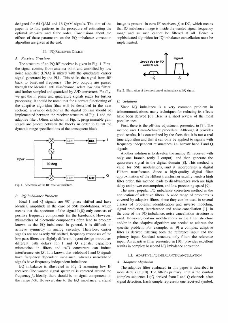
errors. This is why the optimal filter order is obviously equal
to 0. Higher orders lead to overfitting the signal model, which
is manifested as the presence of the
because the algorithm considers it as a signal component. The
error function due to step-size for a constant filter order has a
global minimum. Too low value of
significantly change the filter
convergence so slow that the filter can be considered to
diverge for practical purposes
approximately the same as the filter input. On the other hand,
too large value of the step-size makes the algorithm diverge,
and noise is being amplified instead of cancelled.
manifested as diverging from the minimum of the cost
function of the adaptive algorithm.
Fig. 4 suggests that the error function (with respect t
step- size) of the higher order
However, this is not the truth, since
located in a very low order of
and cannot be seen on the plot. In this case, very low value of
step-size, even if the rendered error is the global minimum of
the parameter space, is not feasible for a finite
implementation of the filter. This is why the
suboptimal solution is chosen as the minimum of the error
function in the case of filter order 0.
Fig. 4. Log-linear plot of mean symbol distance error dependence on the
step-size for several filter orders, in the case of 64
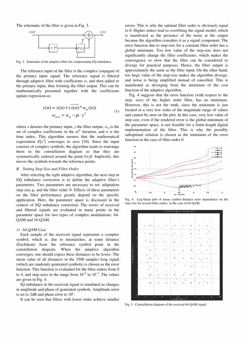
Fig. 5. Constellation diagram of the received 64
errors. This is why the optimal filter order is obviously equal
to 0. Higher orders lead to overfitting the signal model, which
presence of the noise at the output
because the algorithm considers it as a signal component. The
size for a constant filter order has a
global minimum. Too low value of the step-size does not
coefficients, which makes the
convergence so slow that the filter can be considered to
diverge for practical purposes. Hence, the filter output is
approximately the same as the filter input. On the other hand,
size makes the algorithm diverge,
amplified instead of cancelled. This is
manifested as diverging from the minimum of the cost
function of the adaptive algorithm.
the error function (with respect to the
higher order filter, has no minimum.
the truth, since the minimum is just
very low order of the magnitude range of values
and cannot be seen on the plot. In this case, very low value of
even if the rendered error is the global minimum of
the parameter space, is not feasible for a finite-length digital
implementation of the filter. This is why the possibly
suboptimal solution is chosen as the minimum of the error
lter order 0.
linear plot of mean symbol distance error dependence on the
size for several filter orders, in the case of 64-QAM.
Constellation diagram of the received 64-QAM signal.
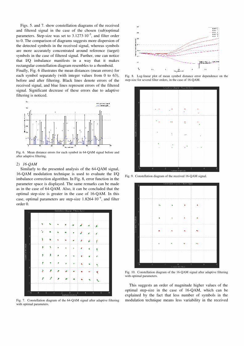
Figs. 5. and 7. show constellation diagrams of the received
and filtered signal in the case of the chosen (sub)optimal
parameters. Step-size was set to 3.1273⋅10−5
, and filter order
to 0. The comparison of diagrams suggests more dispersion of
the detected symbols in the received signal, whereas symbols
are more accurately concentrated around reference (target)
symbols in the case of filtered signal. Further, one can notice
that I/Q imbalance manifests in a way that it makes
rectangular constellation diagram resembles to a rhomboid.
Finally, Fig. 6 illustrates the mean distances (mean errors) for
each symbol separately (with integer values from 0 to 63),
before and after filtering. Black lines denote errors of the
received signal, and blue lines represent errors of the filtered
signal. Significant decrease of these errors due to adaptive
filtering is noticed.
Fig. 6. Mean distance errors for each symbol in 64-QAM signal before and
after adaptive filtering.
2) 16-QAM
Similarly to the presented analysis of the 64-QAM signal,
16-QAM modulation technique is used to evaluate the I/Q
imbalance correction algorithm. In Fig. 8, error function in the
parameter space is displayed. The same remarks can be made
as in the case of 64-QAM. Also, it can be concluded that the
optimal step-size is greater in the case of 16-QAM. In this
case, optimal parameters are step-size 1.8264⋅10−4
, and filter
order 0.
Fig. 7. Constellation diagram of the 64-QAM signal after adaptive filtering
with optimal parameters.
Fig. 8. Log-linear plot of mean symbol distance error dependence on the
step-size for several filter orders, in the case of 16-QAM.
Fig. 9. Constellation diagram of the received 16-QAM signal.
Fig. 10. Constellation diagram of the 16-QAM signal after adaptive filtering
with optimal parameters.
This suggests an order of magnitude higher values of the
optimal step-size in the case of 16-QAM, which can be
explained by the fact that less number of symbols in the
modulation technique means less variability in the received
signal, which further means that the adaptive algorithm does
not need too low step-size in order to converge. Figs. 9. and
10. show constellation diagrams of the received and filtered
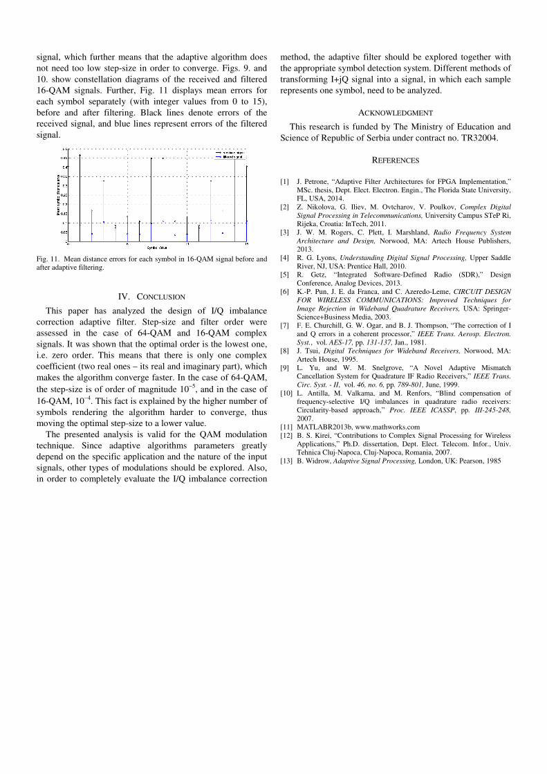
16-QAM signals. Further, Fig. 11 displays mean errors for
each symbol separately (with integer values from 0 to 15),
before and after filtering. Black lines denote errors of the
received signal, and blue lines represent errors of the filtered
signal.
Fig. 11. Mean distance errors for each symbol in 16-QAM signal before and
after adaptive filtering.
IV. CONCLUSION
This paper has analyzed the design of I/Q imbalance
correction adaptive filter. Step-size and filter order were
assessed in the case of 64-QAM and 16-QAM complex
signals. It was shown that the optimal order is the lowest one,
i.e. zero order. This means that there is only one complex
coefficient (two real ones – its real and imaginary part), which
makes the algorithm converge faster. In the case of 64-QAM,
the step-size is of order of magnitude 10−5
, and in the case of
16-QAM, 10−4
. This fact is explained by the higher number of
symbols rendering the algorithm harder to converge, thus
moving the optimal step-size to a lower value.
The presented analysis is valid for the QAM modulation
technique. Since adaptive algorithms parameters greatly
depend on the specific application and the nature of the input
signals, other types of modulations should be explored. Also,
in order to completely evaluate the I/Q imbalance correction
method, the adaptive filter should be explored together with
the appropriate symbol detection system. Different methods of
transforming I+jQ signal into a signal, in which each sample
represents one symbol, need to be analyzed.
ACKNOWLEDGMENT
This research is funded by The Ministry of Education and
Science of Republic of Serbia under contract no. TR32004.
REFERENCES
[1] J. Petrone, “Adaptive Filter Architectures for FPGA Implementation,”
MSc. thesis, Dept. Elect. Electron. Engin., The Florida State University,
FL, USA, 2014.
[2] Z. Nikolova, G. Iliev, M. Ovtcharov, V. Poulkov, Complex Digital
Signal Processing in Telecommunications, University Campus STeP Ri,
Rijeka, Croatia: InTech, 2011.
[3] J. W. M. Rogers, C. Plett, I. Marshland, Radio Frequency System
Architecture and Design, Norwood, MA: Artech House Publishers,
2013.
[4] R. G. Lyons, Understanding Digital Signal Processing, Upper Saddle
River, NJ, USA: Prentice Hall, 2010.
[5] R. Getz, “Integrated Software-Defined Radio (SDR),” Design
Conference, Analog Devices, 2013.
[6] K.-P. Pun, J. E. da Franca, and C. Azeredo-Leme, CIRCUIT DESIGN
FOR WIRELESS COMMUNICATIONS: Improved Techniques for
Image Rejection in Wideband Quadrature Receivers, USA: Springer-
Science+Business Media, 2003.
[7] F. E. Churchill, G. W. Ogar, and B. J. Thompson, “The correction of I
and Q errors in a coherent processor,” IEEE Trans. Aerosp. Electron.
Syst., vol. AES-17, pp. 131-137, Jan., 1981.
[8] J. Tsui, Digital Techniques for Wideband Receivers, Norwood, MA:
Artech House, 1995.
[9] L. Yu, and W. M. Snelgrove, “A Novel Adaptive Mismatch
Cancellation System for Quadrature IF Radio Receivers,” IEEE Trans.
Circ. Syst. - II, vol. 46, no. 6, pp. 789-801, June, 1999.
[10] L. Antilla, M. Valkama, and M. Renfors, “Blind compensation of
frequency-selective I/Q imbalances in quadrature radio receivers:
Circularity-based approach,” Proc. IEEE ICASSP, pp. III-245-248,
2007.
[11] MATLABR2013b, www.mathworks.com
[12] B. S. Kirei, “Contributions to Complex Signal Processing for Wireless
Applications,” Ph.D. dissertation, Dept. Elect. Telecom. Infor., Univ.
Tehnica Cluj-Napoca, Cluj-Napoca, Romania, 2007.
[13] B. Widrow, Adaptive Signal Processing, London, UK: Pearson, 1985