optimal selection of weighting functions by genetic
TRANSCRIPT

HAL Id: hal-01361861https://hal.archives-ouvertes.fr/hal-01361861
Submitted on 7 Sep 2016
HAL is a multi-disciplinary open accessarchive for the deposit and dissemination of sci-entific research documents, whether they are pub-lished or not. The documents may come fromteaching and research institutions in France orabroad, or from public or private research centers.
L’archive ouverte pluridisciplinaire HAL, estdestinée au dépôt et à la diffusion de documentsscientifiques de niveau recherche, publiés ou non,émanant des établissements d’enseignement et derecherche français ou étrangers, des laboratoirespublics ou privés.
Optimal selection of weighting functions by geneticalgorithms to design H∞ Anti-roll bar controllers for
heavy vehiclesvan Tan Vu, Olivier Sename, Luc Dugard, Peter Gaspar
To cite this version:van Tan Vu, Olivier Sename, Luc Dugard, Peter Gaspar. Optimal selection of weighting functionsby genetic algorithms to design H∞ Anti-roll bar controllers for heavy vehicles. VSDIA 2016 - 15thMini Conference on Vehicle System Dynamics, Identification and Anomalies, Nov 2016, Budapest,Hungary. �hal-01361861�

1
OPTIMAL SELECTION OF WEIGHTING FUNCTIONS BY GENETIC ALGORITHMS TO DESIGN H∞ ANTI-ROLL BAR CONTROLLERS FOR
HEAVY VEHICLES
Van Tan VU1, Olivier SENAME1, Luc DUGARD1, Peter GASPAR2
1Univ. Grenoble Alpes and CNRS, GIPSA-lab, F-38402 Grenoble Cedex, France E-mail: {Van-Tan.Vu, olivier.sename, luc.dugard}@gipsa-lab.grenoble-inp.fr
2Systems and Control Laboratory, Institute for Computer Science and Control, Hungarian Academy of Sciences, Kende u. 13-17, H-1111 Budapest, Hungary
E-mail: [email protected]
ABSTRACT
Multi-criterion optimization is so far popular for many complex engineering problems. The objective of active anti-roll bar of heavy vehicles is to maximize roll stability to prevent rollover in dangerous cases. However, such a performance objective must be balanced with the energy consumption of the anti-roll bar system, which is not a trivial task. In a previous work, the authors proposed an H∞ active anti-roll bar controller for which the weighting functions were chosen by trials and errors during the design step. In this paper, Genetic Algorithms (GAs) are proposed to find optimal weighting functions for the H∞ control synthesis. Such a general procedure is applied to the case of active anti-roll bar control in heavy vehicles. Thanks to GAs, the conflicting objectives between roll stability and torques generated are handled using one high level parameter only. The multi-criterion optimization solution is illustrated via the Pareto frontier. Simulations, performed in the frequency and time domains, emphasize the efficiency of the proposed method.
Keywords: H∞ control, Genetic Algorithms, Heavy vehicle, Active anti-roll bar control, Rollover, Roll stability.
1. INTRODUCTION
1.1 Context
Rollover of heavy vehicle is an important road safety problem world-wide. Although rollovers are relatively rare events, they are usually deadly accidents when they occur. Moreover, the roll stability loss is the main cause of traffic accidents in which heavy vehicles are involved. In order to improve the roll stability, several schemes with possible active intervention into the vehicle dynamics were proposed. One of them employs active anti-roll bars, that is, a pair of hydraulic actuators which generates a stabilizing moment to counter balance the overturning moment [17].
On the other hand, the H∞ control design approach is an efficient tool for improving the performance of a closed-loop system in pre-defined frequency ranges. The key step of the H∞ control design is the selection of weighting functions. In many applications, the difficulty in choosing these functions still increases as performance specification is not accurately defined i.e., it is simply to achieve the best possible performance (optimal design) or to achieve an optimally joint improvement of more than one objective (multi-objectives design). So the weighting functions optimization to satisfy

2
the desired performances is still an open problem. Recently, Genetic Algorithms were used in [1] and [10], their formulation well suited for this type of problematic [4].
1.2 Related works
Some of the control methods applied to active anti-roll bar control on heavy vehicle are briefly recalled below:
a- Optimal control: Sampson et al [12], [13], [14] proposed a state feedback controller which was designed by finding an optimal controller based on a linear quadratic regulator (LQR) for single unit and articulated heavy vehicles.
The LQR was also applied to an integrated model including an electronic servo-valve hydraulic damper model and a yaw-roll model of a single unit heavy vehicle. The input current of the electronic servo-valve is the input control signal [17].
b- Neural network control: A reinforcement learning algorithm using neural networks was used to improve the roll stability for a single unit heavy vehicle [2].
c- Robust control (LPV): Gaspar et al [5], [6], [7] applied Linear Parameter Varying techniques to control active anti-roll bars combined with active brakes on a single unit heavy vehicle. The forward velocity was the varying parameter.
1.3 Paper contribution
Based on the H∞ active anti-roll bar control presented by the authors in [18], this paper proposes the use of Genetic Algorithms to define automatically the weighting functions. Hence the following contributions are brought:
- The Genetic algorithms method is applied to define the weighting functions of the H∞ robust controller for active anti-roll bar system on the single unit heavy vehicle. Thanks to GAs, the conflicting objectives between the normalized load transfers and the generated torques are handled using a single high level parameter only, denoted α.
- The simulation results in frequency and time domains show the normalized load transfers at two axles when the tuning parameter value α moves from 0 to 1, compared with the case of passive anti-roll bar and the results of [18]. In time domain, a cornering manoeuvre is used for the heavy vehicle. The forward velocity is considered up to 160 km/h to evaluate the roll stability and to determine the maximal velocity at which the normalized load transfers and the generated torques reach their limits.
The paper is organised as follows: Section 2 gives a brief introduction about multi-objective optimization using GAs. Section 3 presents the model of a single unit heavy vehicle. Section 4 develops the H∞ control synthesis to prevent rollover of heavy vehicles. Section 5 illustrates how to use the GAs to define the weighting functions of the H∞ active anti-roll bar. Section 6 presents some simulation results in frequency and time domains. Finally, some conclusions are drawn in section 7.
2. GENETIC ALGORITHMS AND MULTI-CRITERION OPTIMIZATION
2.1 Genetic algorithms
GAs are now widely used since the first study in [9], confirmed by a popular theory-oriented book [8] and an application-oriented book [3]. The algorithms are
3
based on the natural selection mechanism and have been proven to be very effective in optimization in many real applications such as finance and investment strategies, robotics, engineering design, telecommunications, etc. They are likely global optimization techniques (despite the high computational expense) using probabilistic, multi-points search, random combination (crossover, mutation) and information of previous iteration to evaluate and improve the population. A great advantage of GAs compared with other searching methods (for example gradient methods) is that they search regardless of the nature of the objective functions and constraints.
GAs initialize with a random population which evolves through genetic operations: selection, crossover and mutation. By using a selection process, the fittest individuals based on their fitness values are chosen; crossover and mutation are then applied to create the new population. The genetic operation on individuals continues until the optimization criterion is satisfied or a certain number of generations is reached.
Fitness function: The fitness of an individual is used to choose between “good” and “bad” individuals. An individual with a high fitness has a great chance to be selected.
Selection: This step is to sort and copy individuals by order of satisfaction of the fitness function. The higher the value of the fitness, associated to an individual, the greater the individual's chances to be selected to participate in the next generation. “Proportionate” [9] and “tournament” [11] selections are the most popular methods.
Crossover: This main operation acting on the population of parents is an exchange of parts of chains between two selected individuals (parents) to form two new individuals (children). This exchange may be due either to a single or multiple points.
Mutation: Mutation operates on a single individual by randomly changing a part of it. In the binary coding case, it is done by reversing one or more bits in a chromosome.
2.2 Multi-criterion optimization
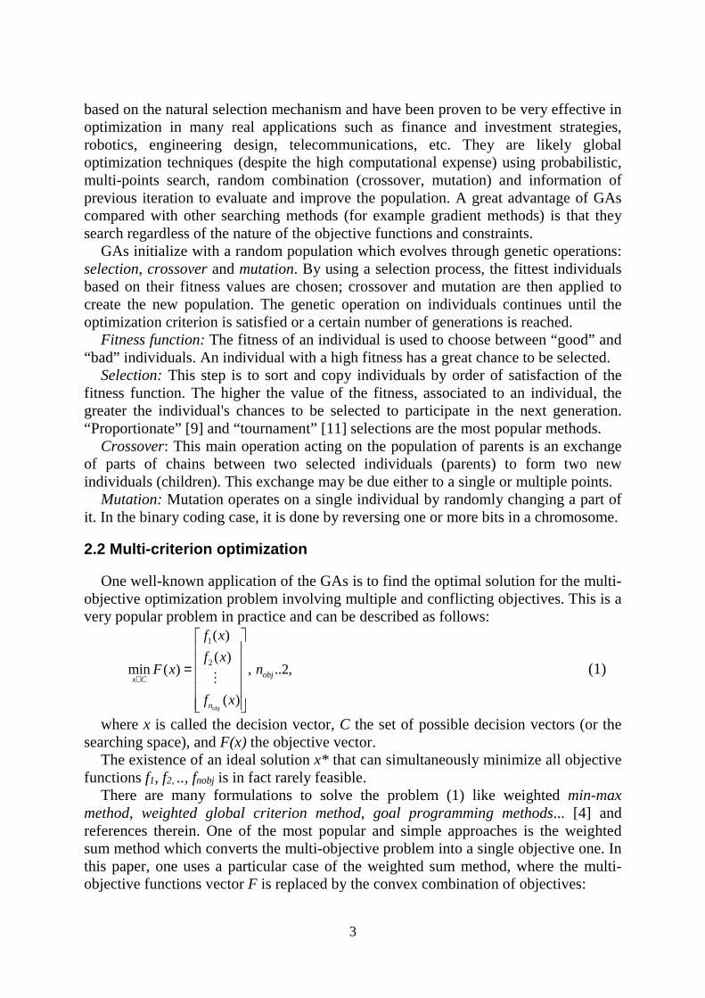
One well-known application of the GAs is to find the optimal solution for the multi-objective optimization problem involving multiple and conflicting objectives. This is a very popular problem in practice and can be described as follows:
1
2
( )
( )min ( ) , ..2,
( )obj
objx C
n
f x
f xF x n
f x
∈
=
M (1)
where x is called the decision vector, C the set of possible decision vectors (or the searching space), and F(x) the objective vector.
The existence of an ideal solution x* that can simultaneously minimize all objective functions f1, f2, .., fnobj is in fact rarely feasible.
There are many formulations to solve the problem (1) like weighted min-max method, weighted global criterion method, goal programming methods... [4] and references therein. One of the most popular and simple approaches is the weighted sum method which converts the multi-objective problem into a single objective one. In this paper, one uses a particular case of the weighted sum method, where the multi-objective functions vector F is replaced by the convex combination of objectives:
4
1 1
min ( ), . , 1obj objn n
i i ii i
J f x s t x Cα α= =
= ∈ =∑ ∑ (2)
The vector 1 2( , ,..., )objnα α α α= represents the gradient of function J. By using
various sets of α, one can generate several points in the Pareto set [4].
3. SINGLE UNIT HEAVY VEHICLE MODEL
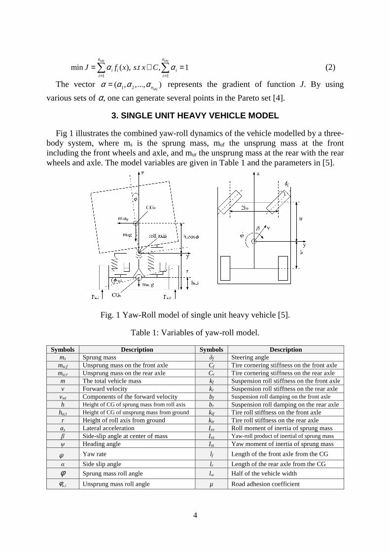
Fig 1 illustrates the combined yaw-roll dynamics of the vehicle modelled by a three-body system, where ms is the sprung mass, muf the unsprung mass at the front including the front wheels and axle, and mur the unsprung mass at the rear with the rear wheels and axle. The model variables are given in Table 1 and the parameters in [5].
Fig. 1 Yaw-Roll model of single unit heavy vehicle [5].
Table 1: Variables of yaw-roll model.
Symbols Description Symbols Description ms Sprung mass δf Steering angle mu;f Unsprung mass on the front axle Cf Tire cornering stiffness on the front axle mu;r Unsprung mass on the rear axle Cr Tire cornering stiffness on the rear axle m The total vehicle mass kf Suspension roll stiffness on the front axle v Forward velocity kr Suspension roll stiffness on the rear axle
vwi Components of the forward velocity bf Suspension roll damping on the front axle h Height of CG of sprung mass from roll axis br Suspension roll damping on the rear axle
hu;i Height of CG of unsprung mass from ground ktf Tire roll stiffness on the front axle r Height of roll axis from ground ktr Tire roll stiffness on the rear axle ay Lateral acceleration Ixx Roll moment of inertia of sprung mass β Side-slip angle at center of mass Ixz Yaw-roll product of inertial of sprung mass ψ Heading angle Izz Yaw moment of inertia of sprung mass
ψ
Yaw rate l f Length of the front axle from the CG
α Side slip angle lr Length of the rear axle from the CG
φ Sprung mass roll angle lw Half of the vehicle width
,u iφ Unsprung mass roll angle µ Road adhesion coefficient

5
In the vehicle modelling, the differential equations of motion of the yaw-roll dynamics of the single unit vehicle, i.e. the lateral dynamics (3.1), the yaw moment (3.2), the roll moment of the sprung mass (3.3), the roll moment of the front (3.4) and the rear (3.5) unsprung masses, are formalized in the equations (3):
2
( )
( ) ( ) ( ) ( )
( ) ( )
( )( ) ( )
s yf yr
xz zz yf f yr r
xx s xz s s f uf f uf ARf f
r ur r ur ARr r
yf uf uf uf uf uf tf uf f uf
mv m h F F
I I F l F l
I m h I m gh m vh k b M U
k b M U
rF m v r h m gh k k
β ψ φ
φ ψ
φ ψ φ β ψ φ φ φ φ
φ φ φ φ
β ψ φ φ φ φ
+ − = +
− + = −
+ − = + + − − − − + +
− − − − + +
− = − + + − + −
( )
( )( ) ( ) ( )
f uf ARf f
yr ur ur ur ur ur tr ur r ur r ur ARr r
b M U
rF m v r h m gh k k b M U
φ φ
β ψ φ φ φ φ φ φ
+ − + +
− = − + − − + − + − + +
(3.1) (3.2) (3.3) (3.4) (3.5)
The lateral tire forces Fyf and Fyr in the direction of velocity at the wheel ground contact points are modelled by a linear stiffness as:
yf f f
yr r r
F C
F C
µ αµ α
= =
(4)
where the tyre side slip angles are given as:
ff f
rr
l
v
l
v
ψα β δ
ψα β
= − + −
= − +
(5)
The moment of passive anti-roll bar impacts the unsprung and sprung masses at the front and rear axles as follows [17], [18]:
2
2 2
2
2 2
4 4
4 4
A B AARf AOf AOf uf
A B AARr AOr AOr ur
t t tM k k
c c
t t tM k k
c c
φ φ
φ φ
= −
= −
(6)
where kAOf , kAOr are respectively the torsional stiffness of the anti-roll bar at the front and rear axles, tA half the distance of the two suspensions, tB half the distance of the chassis and c the length of the anti-roll bars’ arm.
Using the previous equation, the single unit heavy vehicle can be represented by the linear system in the state space form (7):
1 2x Ax B w B u
y Cx
= + +
=
(7)
with the state vector: uf urx β ψ ϕ ϕ ϕ ϕ =
, the disturbance input: fw δ =
6
the control inputs: f ru U U = and the output vector: uf ury β ψ ϕ ϕ ϕ ϕ =
.
4. H∞ CONTROL SYNTHESIS OF ACTIVE ANTI-ROLL BAR ON HEAVY VEHICLES
4.1 Control objective, problem statement
The objective of the active anti-roll bar control system is to maximize the roll stability of the vehicle. Usually, an imminent rollover is detected when the calculated normalized load transfer reaches 1 (or -1), as explained hereafter. First, the lateral load transfer can be given by:
u uz
w
kF
l
ϕ∆ = (8)
where ku is the stiffness of tire, φu the roll angle of the unsprung mass and lw the half of vehicle’s width. Then, the lateral load transfer can be normalized w.r.t. the total axle load Fz as follows:
z
z
FR
F
∆= (9)
The normalized load transfer R=±1 corresponds to the largest possible load transfer. In that case, the inner wheel in the bend lifts off.
While attempting to minimize the load transfer, it is also necessary to constrain the roll angles between the sprung and unsprung masses (φ-φu) so that they stay within the limits of the suspension travel (7-8deg), see [5].
The performance characteristic which is of most interest when designing the active anti-roll bar, is then the normalized load transfer. The chosen control objective is to minimize the effect of the steering angle on the normalized load transfer R, in the H∞ framework. As explained later, the limitation of the torques Uf;r generated by the actuators is also crucial for practical implementation.
4.2 Background on H∞ control
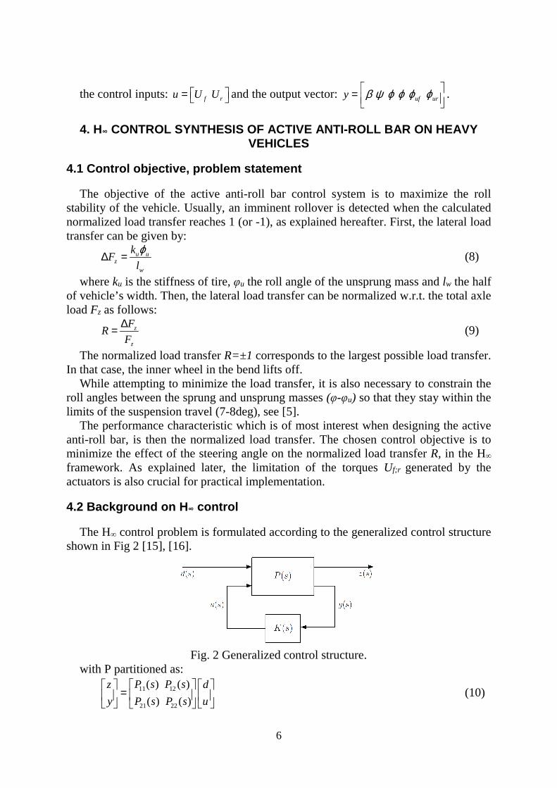
The H∞ control problem is formulated according to the generalized control structure shown in Fig 2 [15], [16].
Fig. 2 Generalized control structure.
with P partitioned as:
11 12
21 22
( ) ( )
( ) ( )
P s P sz d
y P s P s u
=
(10)

7
and ( ).u K s y= , which yields:
[ ] 1
11 12 22 21( , ) :l
zF P K P P K I P K P
d
− = = + −
(11)
The aim is to design a controller K that stabilizes the closed loop system and also reduces the signal transmission path from disturbances d to performance outputs z. This problem is then to find a controller K which minimizes γ such that
( , )lF P K γ∞
< (12)
By minimizing a suitably weighted version of ( , )lF P K the control aim is achieved.
4.3 H∞ control synthesis for the active anti-roll bar of the single unit heavy vehicle model
In this section, the H∞ control design is presented for the active anti-roll bar system on a single unit heavy vehicle. Consider the closed-loop system given in Fig 3, which includes the feedback structure of the nominal model G, the controller K and the weighting functions Wij. In this diagram, Uf and Ur are the control inputs, y1 and y2 are the measured outputs, n1 and n2 are the measurement noises. δf is the steering angle considered as a disturbance signal, which is set by the driver. The variables z1, z2, z3, z4 and z5 represent the performance outputs.
Fig. 3 G-K control structure of H∞ active anti-roll bar control.
According to Fig 3, the concatenation of the linear model (7) with performance weighting functions lead to the state space representation of P(s):
1 2
1 11 12
2 21 22
A B BX X
Z C D D W
Y UC D D
=
(13)
with the exogenous input (disturbance): 1 2[ ]W d n n=
the control input: [ ]Tf rU U U= ; where Uf /Ur are the torques at the front/rear axles.
the performance output vector: 1 2 3 4 5[ ]TZ z z z z z=
the measured output vector: [ ]TyY a ϕ=
and A, B1, B2, C1, D11, D12, C2, D21, D22 are matrices of appropriate dimensions.
8
The next section proposes an automatic and systematic way to obtain the optimal weighting functions used to solve the H∞ control design problem.
5. SELECTION OF WEIGHTING FUNCTIONS OF H∞ ANTI-ROLL BAR CONTROLLERS BY GENETIC ALGORITHMS
In industrial applications, multiple goals, often conflicting, have to be taken into account. Multi-criterion optimization (MCO) is then a powerful tool to find the best compromise solution balancing the conflicts, and is therefore of great importance in practice. In this section, MCO problem for the weighting function selection of the H∞ active anti-roll bar control on heavy vehicles is introduced and solved using the Genetic algorithms method. But first, the criterion for MCO problem must be defined.
5.1 Optimization objectives
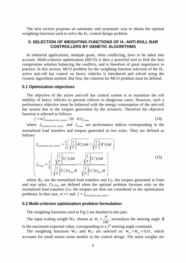
The objective of the active anti-roll bar control system is to maximize the roll stability of heavy vehicles to prevent rollover in dangerous cases. However, such a performance objective must be balanced with the energy consumption of the anti-roll bar system due to the torques generation by the actuators. Therefore the objective function is selected as follows: Normalized_load_transfer Torque(1 )f f fα α= + − (14)
where Normalized_load_transferf and Torquef are performance indices corresponding to the
normalized load transfers and torques generated at two axles. They are defined as follows:
2 2Normalized_load_transfer
0 0
2 2
0 0Torque
2 2max max
0 0
1 1 1( ) ( )
2
1 1( ) ( )
1
2 1 1( ) ( )
T T
f r
T T
f r
T T
f r
f R t dt R t dtT T
U t dt U t dtT T
f
U t dt U t dtT T
= +
= +
∫ ∫
∫ ∫
∫ ∫
(15)
where Rf;r are the normalized load transfers and Uf;r the torques generated at front and rear axles. Uf;rmax are defined when the optimal problem focusses only on the normalized load transfers (i.e. the torques are then not considered in the optimisation problem). In that case, 1α = and Normalized_load_transferf f= .
5.2 Multi-criterion optimization problem formulation
The weighting functions used in Fig 3 are detailed in this part.
The input scaling weight Wd, chosen as 180dWπ= , normalizes the steering angle δf
to the maximum expected value, corresponding to a 10 steering angle command. The weighting functions Wn1 and Wn2 are selected as: 1 2 0.01n nW W= = , which
accounts for small sensor noise models in the control design. The noise weights are

9
chosen as 0.01(m/s2) for the lateral acceleration and 0.01(0/sec) for the derivative of
the roll angle ϕ
[5]. Note that other low pass filters could be selected if needed. The weighting functions Wzi represent the performance outputs (Wz1, Wz2, Wz3, Wz4
and Wz5). The purpose of the weighting functions is to keep small the control inputs, normalized load transfers and the lateral acceleration over a desired frequency range. The weighting functions chosen for performance outputs can be considered as penalty functions, that is, weights should be large in the frequency range where small signals are desired and small where larger performance outputs can be tolerated.
The weighting functions Wz1 and Wz2 corresponding to the front and rear control torques generated by active anti-roll bars are chosen as:
11
1ZW
Z= ; 2
2
1ZW
Z= (16)
The weighting functions Wz3 and Wz4 corresponding to the normalized load transfers at front and rear axles are selected as:
33
1ZW
Z= ; 4
4
1ZW
Z= (17)
The weighting function Wz5 is selected as: 52 53
5 5154 55
Z
Z s ZW Z
Z s Z
+=+
(18)
Here, the weighting function Wz5 corresponds to a design that avoids the rollover situation with the bandwidth of the driver in the frequency range up to more than 4rad/s. This weighting function will directly minimize the lateral acceleration when it reaches the critical value, to avoid the rollover.
The parameters Zij are constant. From equations (16) - (18), the following variables will then be defined: Z1, Z2, Z3,
Z4, Z51, Z52, Z53, Z54, Z55. The MCO problem for the H∞ active anti-roll bar control can be defined as:
{ }_ _
1 2 3 4 51 52 53 54 55
min ( ), ( ) :
: [ , , , , , , , , ] |
T
Normalized load transfer Torquep P
T l u
f p f p f f
P p Z Z Z Z Z Z Z Z Z R p p p
∈ =
= = ∈ ≤ ≤ (19)
where f(p) is the vector of objectives, p the vector of weighting function parameters, pl and pu the lower and upper bounds of the weighting function selection.
The lower and upper bounds of the weighting function parameters are given in Table (2). Besides the minimization of the objective function from equations (14) and (19), we also have to account for the limitations of the normalized load transfers, roll angle of suspensions as well as torques generated at each axle. These limitations are considered as the optimality conditions (binding conditions) shown in the Table (3).
Table 2: Lower and upper bounds of the weighting functions.
Wz1 Wz2 Wz3 Wz4 Wz5 Z1 Z2 Z3 Z4 Z51 Z52 Z53 Z54 Z55
Lower bound
50 50 0.1 0.1 0.5 1
3000 1 1 0.001

10
Upper bound
300000 300000 10 10 100 1 500 1
0.001 2
Table 3: Binding conditions.
No Note Maximum value Unit
1 ufφ φ− < 7 deg
2 urφ φ− < 7 deg
3 fR < 1 -
4 rR < 1 -
5 fU < 120000 Nm
6 rU < 120000 Nm
5.3 Genetic operation
The selection method used in this paper is the proportionate selection developed by Holland [9]. This method assigns a probability of selection to each individual, proportional to its relative fitness. Proportionate selection can be illustrated by a roulette wheel. The crossover happens with a probability of 0.9 and the mutation happens with a very small probability 0.095.
The proposed weighting function optimization procedure for H∞ active anti-roll bar control synthesis is as follows:
Step 1: Initialize with the weighting functions as in the previous paper [18], the vector of weighting function selected as p=p0.
Step 2: Select lower bound, upper bound, scaling factor, offset and start point. Step 3: Format optimal algorithm, select the vector of objectives with the variation
of switch value from 0 to 1 and then solve the minimization problem. Step 4: Select the individuals, apply crossover and mutation to generate a new
generation: p=pnew. Step 5: Evaluate the new generation by comparing with the binding conditions. If
the criteria of interest are not satisfied, go to step 3 with p=pnew; else, stop and save the best individual: popt=pnew.
6. SIMULATION RESULTS
6.1 Optimization results
Thanks to the Genetic algorithms method, Table (4) synthesis the values of the variables Zi, Z5j in five cases for [1;0.85;0.65;0.5;0]α = . When 1α = , it means that
Normalized_load_transferf f= , the optimal problem focuses only on the normalized load
transfers and when 0α = , it means that Torquef f= , the optimal problem focuses only
on the torques generated.

11
Table 4: Optimization results for the weighting functions of H∞ active anti-roll bar.
Controllers Wz1 Wz2 Wz3 Wz4 Wz5 Z1 Z2 Z3 Z4 Z51 Z52 Z53 Z54 Z55
SSSC2016 [18]
150000 200000 1 1 1 0.0005 50 100 0.01
1α = 258762.34 259996.91 0.91 0.64 0.97 0.46 392.54 801.38 0.22
0.85α = 273598.36 295104.17 0.45 0.26 1.17 0.80 334.15 968.50 0.16
0.65α = 112322.78 110837.28 0.72 0.75 0.63 0.54 139.23 97.46 0.02 0.5α = 166902.22 196036.53 1.09 0.92 0.97 0.0005 54.19 116.64 0.01
0α = 50 50 1.59 0.83 0.50 0.43 1 683.05 0.024
Fig. 4 shows the conflicting relation between the normalized load transfers and torques generated with some Pareto-optimal points, computed for the active anti-roll bar on heavy vehicle. They are generated for different values of α in the range of [0;1]. For α=0, Torquef is minimized and conversely for α=1, Normalized_load_transferf is minimized.
Figure. 4 The optimization results of some points in the Pareto frontier for the active anti-roll bar on heavy vehicle.
6.2 Evaluation of optimization results in frequency domain
The limited bandwidth of the driver must be considered up to 4rad/s to identify any resonances in the response that may be excited by the driver [5]. Therefore, it is necessary to consider the behavior of the heavy vehicle in a wider frequency range. In this section, the frequency response of heavy vehicle is shown in the nominal parameters case of the single unit heavy vehicle considered, characterized by the sprung mass ms= 12487kg, the forward velocity V at 70Km/h and the road adhesion coefficient µ= 1.
12
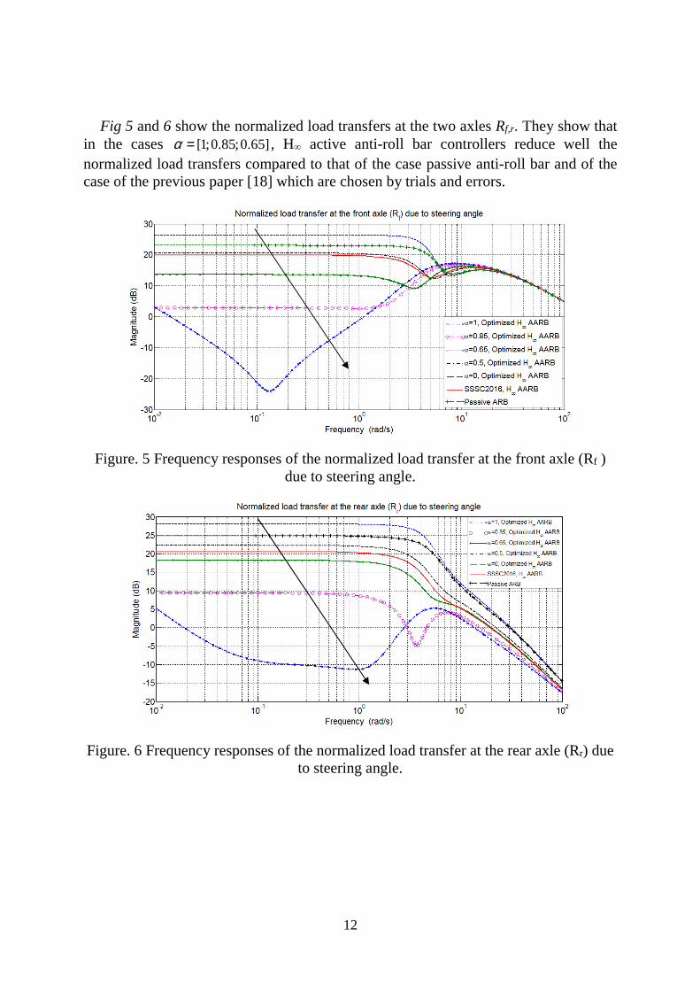
Fig 5 and 6 show the normalized load transfers at the two axles Rf,r. They show that
in the cases [1;0.85;0.65]α = , H∞ active anti-roll bar controllers reduce well the normalized load transfers compared to that of the case passive anti-roll bar and of the case of the previous paper [18] which are chosen by trials and errors.
Figure. 5 Frequency responses of the normalized load transfer at the front axle (Rf ) due to steering angle.
Figure. 6 Frequency responses of the normalized load transfer at the rear axle (Rr) due to steering angle.

13
6.3 Evaluation of optimization results in time domain
In this section, the considered vehicle maneuver is cornering [5].
Figure. 7 Steering angle δf during cornering maneuver.
Fig 8a,b show the normalized load transfers and Fig 8c,d show the torques generated at two axles when the forward velocity is considered at 70Km/h. When the value of α increases, the controllers reduce the normalized load transfers, but the torques generated by the actuators are higher. This fulfills consistently the objective of optimal design.
Figure. 8 Time responses of the normalized load transfers (Rf,r) and torques generated at the two axles.
The forward velocity of the heavy vehicle continuously varies during operation of the heavy vehicle, especially in the case of an emergency. The rollover of heavy

14
vehicle often occurs for forward velocity within 60 to 110 Km/h. In Fig 9 and 10 we consider the forward velocity of the heavy vehicle up to 160 Km/h in order to evaluate the roll stability, as well as to determine the maximum forward velocity at which the normalized load transfers and the torques generated reach the limitations. In what follows, the disturbance is the steering angle (δf) corresponding to a cornering maneuver. From Fig 9, we can see that the maximum absolute value of normalized load transfers at the front axle reaches the limit “1” in the case of [1;0.85;0.65;0.5]α = where the forward velocities are respectively 134, 131, 123, 104 Km/h. Note that in the previous paper [18] we got 107 Km/h for the forward velocity.
Figure. 9 Effect of the forward velocity on the normalized load transfer: front axle Rf.
Considering Fig 10, the maximum absolute value of the normalized load transfers at the rear axle reaches the limit “1” in the case of [1;0.85;0.65;0.5]α = where the forward velocities are respectively 130, 125, 112, 97 Km/h. Note that in the previous paper [18], we got 104 Km/h for the forward velocity. In fact, the forward velocities of heavy vehicles are often considered up around 100 Km/h, so that choosing α between 1 and 0.65 is convenient.

15
Figure. 10 Effect of the forward velocity on the normalized load transfer: rear axle Rr.
7. CONCLUSIONS
In this paper, a weighting function optimization procedure using GAs for H∞ active anti-roll bar control on single unit heavy vehicle has been proposed. The conflicting objectives between the normalized load transfers and generated torques are handled using only one high level parameter, which is a great advantage to solve the multi-objective control problem. The simulation results in frequency and time domains have shown the efficiency of GAs in finding a suitable controller to satisfy the desired performance objectives.
Even if other structures for the weighting functions could be used, the ones used in this paper are shown to be simple enough while being efficient to solve the problem. For future works, the comparison with an LPV controller (scheduled by the forward vehicle velocity) will be of interest.
8. REFERENCES
[1] Alfaro-Cid, E., McGookin, E.W., and Murray-Smith, D.J. Optimisation of the weighting functions of an H∞ controller using genetic algorithms and structured genetic algorithms. International Journal of Systems Science, 2008. (p.335–347). [2] Boada, M., Boada, B., Quesada, A., Gaucha, A., and Daz, V. Active roll control using reinforcement learning for a single unit heavy vehicle. In 12th IFToMM World Congress. Besancon, France, 2007. [3] Davis, L.D. Handbook of genetic algorithms. Van Nostrand Reinhold, 1991. [4] Do, A.L.; B., Soualmi; Lozoya-Santos, Jesus; Sename, O.; Dugard, L.; Ramirez-Mendoza, R. Optimization of weighting function selection for H∞ control of semi-active suspensions, 12th Mini conference on vehicle system dynamics, identification and anomalies (VSDIA 2010). Budapest, Hungary, 2010. [5] Gaspar, P., Bokor, J., and Szaszi, I. The design of a combined control structure to prevent the rollver of heavy vehicles. European Journal of Control, 2004. (p.148–162). [6] Gaspar, P., Bokor, J., and Szaszi, I. Reconfigurable control structure to prevent the rollover of heavy vehicles. Control Engineering Practice, 2005a. (p.699–711). [7] Gaspar, P., Szabo, Z., and Bokor, J. Prediction based combined control to prevent the rollover of heavy vehicles. In Proceedings of the 13th Mediterranean Conference on Control and Automation. Limassol, Cyprus, 2005b. [8] Goldberg, D. Genetic Algorithms in Searching Optimisation and Machine Learning. Addison-Wesley Longman, 1989. [9] Holland, H.J. (1975). Adaptation in natural and artificial systems, an introductory analysis with application to biology, control and artificial intelligence. Ann Arbor, The university of Michigan Press. [10] Kitsios, I. and Pimenides, T. H∞ controller design for a distillation column using genetic algorithms. Mathematics and Computers in Simulation, 2002.

16
[11] Miller, B.L., Miller, B.L., Goldberg, D.E., and Goldberg, D.E. Genetic algorithms, tournament selection, and the effects of noise. Complex Systems, 1995. (p.193–212). [12] Sampson, D. and Cebon, D. An investigation of roll control system design for articulated heavy vehicles. In 4th International symposium on Advanced Vehicle Control, AVEC1998. Nagoya, Japan, 1998. [13] Sampson, D. and Cebon, D. Achievable roll stability of heavy road vehicles. In Proceedings of the Institution of Mechanical Engineers, Part D: Journal of Automobile Engineering, volume 217, United Kingdom, 2002. [14] Sampson, D. and Cebon, D. Active roll control of single unit heavy road vehicles. Vehicle System Dynamics: International Journal of Vehicle Mechanics and Mobility, 40(4), 2003. (p.229–270). [15] Scherer, C. and Weiland, S. Linear matrix inequalities in control, University Lecture, 2005. [16] Skogestad, S. and Postlethwaite, I. Multivariable Feedback Control. John Wiley & Sons, 2 edition, 2001. [17] Vu, V.T., Sename, O., Dugard, L., and Gaspar, P. Active anti-roll bar control using electronic servo-valve hydraulic damper on single unit heavy vehicle. In IFAC Symposium on Advances in Automotive Control - 8th AAC 2016, Sweden, 2016. [18] Vu, V.T., Sename, O., Dugard, L., and Gaspar, P. H∞ active anti-roll bar control to prevent rollover of heavy vehicles: a robustness analysis. In IFAC Symposium on System Structure and Control - 6th SSSC 2016, Turkey, 2016.