optimalization of heat transfer for …seaisi.org/file/5b-2 optimalization wchgl pt krakatau...
TRANSCRIPT

SEASI 2018 CONFERENCE , 25-28 JUNE 2018, JAKARTA
Page 1 of 11
OPTIMALIZATION OF HEAT TRANSFER FOR
WATER COOLED HOT GAS LINE IN DEDUSTING
SYSTEM SLAB STEEL PLANT
Dinaryuda Dwi Kurniawan1), Mardono2), Arief Budi Artha3)
Maintenance Service Iron and Steel Making,
PT. Krakatau Steel (Persero) Tbk.
Jl. Industri No 5, Cilegon, Banten 42435 Indonesia
e-mail: [email protected]), [email protected])
Abstract
Dedusting Plant is one of the system that is a part of Slab Steel Plant. This Dedusting
Plant aims to take up hot gas which is produced by Electric Arc Furnace (EAF) on Steel
Making Process. Water Cooled Hot Gas Line is one of heat transfer part of this Dedusting
Plant. Performance of Water Cooled Hot Gas Line can be indicated by the values of the
temperature (T) fluid that flowing in and out.In this Water Cooled Hot Gas Line, The
Temperature of water flowing out, exceed standart temperature. So this high temperature outlet
make the system trip/off. So that need to evaluating heat transfer of water cooled hot gas line
to remove delay process because of the high temperature outlet water cooled hot gas line.
This optimalization aimed to evaluate the heat transfer performance of water flow in a
water cooled duct in section 1 and 2 EAF 6. This sections consisted of three parts, namely inlet
header, pipe line, and outlet header. The inlet header has a diameter nominal pipe 125, the pipe
line has a diameter pipe 76.1 mm, and the outlet header has a diameter nominal pipe 125. The
water entry to inlet header which is has 3 branch in that is come to pipe channel, then from pipe
channel the water exit to the 3 branch out of oulet header. In this optimalization used the theory
heat transfer equation to calculate the performance of heat transfer and use 3D drawing
software to design a new modification on water cooled duct.
The results of the calculation of heat transfer showed that the water cooling system need
to be improve because the design of header and branch are not optimum. Then, based on the
heat transfer calculation, modification can be made for the inlet and outlet header and for the
branch of pipe line. The inlet header and outlet header is changed from nominal diameter pipe
125 to 150. The Branch of pipe line is changed from 3 Branch which have length of cooling
pipe 233.577 meter each part to 6 Branch which are have length of cooling pipe 109.448 meter
each part. So the water that flow to the pipe channel now have a shorter circuit than the
existing.. Optimalization of the Header and the pipe branch show a better heat transfer for the
water cooled hot gas line system on dedusting plant.
Keyword : heat transfer, water cooled duct, header inlet and outlet, branch, pipe line
SEASI 2018 CONFERENCE , 25-28 JUNE 2018, JAKARTA
Page 2 of 11
I. INTRODUCTION
Dedusting Plant is one of the system that is a part of Slab Steel Plant. This Dedusting
Plant aims to take up hot gas which is produced by Electric Arc Furnace (EAF) on Steel
Making Process. In this Dedusting System have a several part, for example : water cooled hot
gas line, canopy, drop out box, forced draught cooler, mixing chamber, bag filter house, ID fan
and etc. The Main problem is in the Water cooled hot gas line.
Water Cooled Hot Gas Line is one of heat transfer part of this Dedusting Plant. This
water cooled hot gas line is a ducting which is consist of pipe-pipe around the wall.
Performance of this water cooled hot gas line can be indicated by the values of the temperature
(T) fluid that flowing in and out. In this Water Cooled Hot Gas Line, The Temperature of water
flowing out in one of this section exceed standart temperature. So this high temperature outlet
make the system trip/off. So that need to evaluating heat transfer of water cooled hot gas line
to remove delay process because of the high temperature outlet water cooled hot gas line. This
High temperature occur in EAF number 6 on section 1 and section 2. The main background of
optimalization necessity was shown in this section. The main problem of the high temperature
of water cooled hot gas line in Dedusting Plant was explained in Section II. Section III
presented the new design of water cooled hot gas line. The result of implementations was
described and analyzed in Section IV. Section V provided the conclusions.
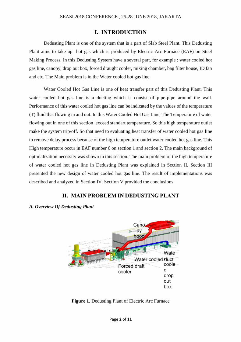
II. MAIN PROBLEM IN DEDUSTING PLANT
A. Overview Of Dedusting Plant
Figure 1. Dedusting Plant of Electric Arc Furnace
Water cooled drop out box
Water cooled duct
Canopy
hood
Forced draft cooler
Filter and stack
SEASI 2018 CONFERENCE , 25-28 JUNE 2018, JAKARTA
Page 3 of 11
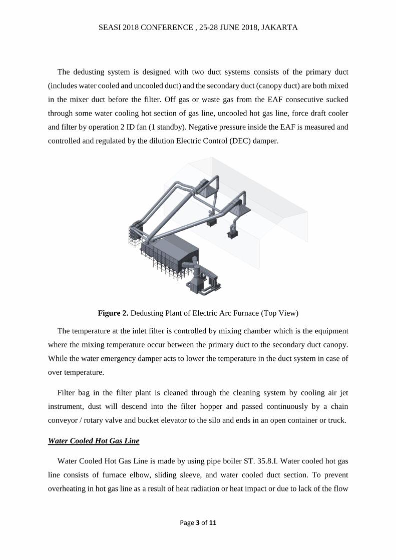
The dedusting system is designed with two duct systems consists of the primary duct
(includes water cooled and uncooled duct) and the secondary duct (canopy duct) are both mixed
in the mixer duct before the filter. Off gas or waste gas from the EAF consecutive sucked
through some water cooling hot section of gas line, uncooled hot gas line, force draft cooler
and filter by operation 2 ID fan (1 standby). Negative pressure inside the EAF is measured and
controlled and regulated by the dilution Electric Control (DEC) damper.
Figure 2. Dedusting Plant of Electric Arc Furnace (Top View)
The temperature at the inlet filter is controlled by mixing chamber which is the equipment
where the mixing temperature occur between the primary duct to the secondary duct canopy.
While the water emergency damper acts to lower the temperature in the duct system in case of
over temperature.
Filter bag in the filter plant is cleaned through the cleaning system by cooling air jet
instrument, dust will descend into the filter hopper and passed continuously by a chain
conveyor / rotary valve and bucket elevator to the silo and ends in an open container or truck.
Water Cooled Hot Gas Line
Water Cooled Hot Gas Line is made by using pipe boiler ST. 35.8.I. Water cooled hot gas
line consists of furnace elbow, sliding sleeve, and water cooled duct section. To prevent
overheating in hot gas line as a result of heat radiation or heat impact or due to lack of the flow

SEASI 2018 CONFERENCE , 25-28 JUNE 2018, JAKARTA
Page 4 of 11
of cooling water, water temperature sensor and flow meter measurement are installed to
monitor each circuit water cooling line.
Furnace elbow or elbow is fixed to face each other with the elbow roof so that under normal
conditions (sliding sleeve close) has a clearance of approximately 50 mm. The distance
between the elbow with a fixed roof can be adjusted via a mechanism elbow sleeve sliding
back and forth with the motor electric drive system (open and close). The main function of the
sliding sleeve is for additional input from atmospheric oxygen so that the exothermic reaction
CO can take place completely in the hot gas line. Under conditions of automatic, sliding
movement of the sleeve is set based mode operating conditions EAF is happening.
Figure 2. Uncooled Duct
Un-cooled duct is made from high resistant material which is steel plate 16Mo3. For
avoiding the over-heating in the un-cooled duct and controlling the inlet temperature of Force
Draft Cooler (FDC), the system is equipped with emergency water dilution damper. Emergency
water dilution damper is designed by using the motor driving system AUMA (open and close)
with the set point temperature sensor at the inlet FDC 550oC so that the temperature un-cooled
would be restrained.
SEASI 2018 CONFERENCE , 25-28 JUNE 2018, JAKARTA
Page 5 of 11
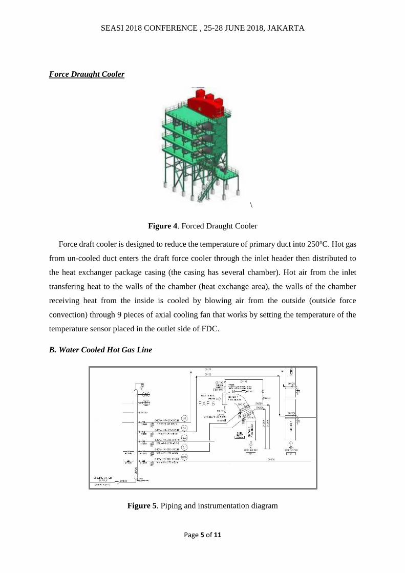
Force Draught Cooler
\
Figure 4. Forced Draught Cooler
Force draft cooler is designed to reduce the temperature of primary duct into 250oC. Hot gas
from un-cooled duct enters the draft force cooler through the inlet header then distributed to
the heat exchanger package casing (the casing has several chamber). Hot air from the inlet
transfering heat to the walls of the chamber (heat exchange area), the walls of the chamber
receiving heat from the inside is cooled by blowing air from the outside (outside force
convection) through 9 pieces of axial cooling fan that works by setting the temperature of the
temperature sensor placed in the outlet side of FDC.
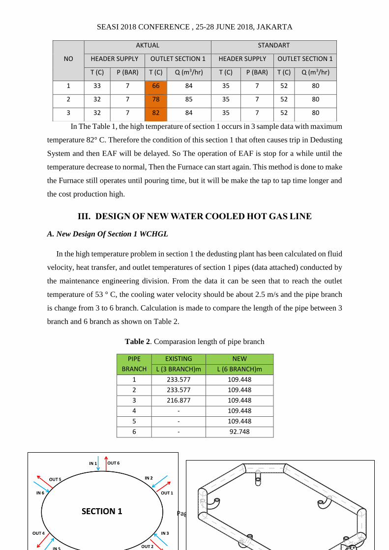
B. Water Cooled Hot Gas Line
Figure 5. Piping and instrumentation diagram

SEASI 2018 CONFERENCE , 25-28 JUNE 2018, JAKARTA
Page 6 of 11
Piping and instrumentation diagram of section 1 and 2 water cooled hot gas line is shown in
the Figure 5. The flue gas flow from EAF to fixed elbow 1, then fixed elbow 2, then come to
Drop Out Box. After DOB the flue gas entry section 1 then section 2. The standart of flow and
temperature is shown on the piping line. Figure 6. Shows that drawing of the section 1 which
have pipe around the wall and have header inlet and outlet. This sections consisted of three
parts, namely inlet header, pipe line, and outlet header. The inlet header has a diameter nominal
pipe 125, the pipe line has a diameter pipe 76.1 mm, and the outlet header has a diameter
nominal pipe 125. The water entry to inlet header which is has 3 branch in that is come to pipe
channel, then from pipe channel the water exit to the 3 branch out of oulet header.
Figure 6. Structure of piping in section 1
Figure 7. Mechanical Drawing of section 1
Table 1. Actual condition of section 1
SEASI 2018 CONFERENCE , 25-28 JUNE 2018, JAKARTA
Page 7 of 11
In The Table 1, the high temperature of section 1 occurs in 3 sample data with maximum
temperature 82° C. Therefore the condition of this section 1 that often causes trip in Dedusting
System and then EAF will be delayed. So The operation of EAF is stop for a while until the
temperature decrease to normal, Then the Furnace can start again. This method is done to make
the Furnace still operates until pouring time, but it will be make the tap to tap time longer and
the cost production high.
III. DESIGN OF NEW WATER COOLED HOT GAS LINE
A. New Design Of Section 1 WCHGL
In the high temperature problem in section 1 the dedusting plant has been calculated on fluid
velocity, heat transfer, and outlet temperatures of section 1 pipes (data attached) conducted by
the maintenance engineering division. From the data it can be seen that to reach the outlet
temperature of 53 ° C, the cooling water velocity should be about 2.5 m/s and the pipe branch
is change from 3 to 6 branch. Calculation is made to compare the length of the pipe between 3
branch and 6 branch as shown on Table 2.
Table 2. Comparasion length of pipe branch
PIPE
BRANCH
EXISTING NEW
L (3 BRANCH)m L (6 BRANCH)m
1 233.577 109.448
2 233.577 109.448
3 216.877 109.448
4 - 109.448
5 - 109.448
6 - 92.748
NO
AKTUAL STANDART
HEADER SUPPLY OUTLET SECTION 1 HEADER SUPPLY OUTLET SECTION 1
T (C) P (BAR) T (C) Q (m3/hr) T (C) P (BAR) T (C) Q (m3/hr)
1 33 7 66 84 35 7 52 80
2 32 7 78 85 35 7 52 80
3 32 7 82 84 35 7 52 80

SEASI 2018 CONFERENCE , 25-28 JUNE 2018, JAKARTA
Page 8 of 11
Figure 8. Ilustation of 6 branch pipe
The results of the calculation on Table 2 show that in 3 branch, length of the pipe is
233.577 meter and for 6 branch, length of the pipe is 109.448 meter. So The Branch of pipe
line is changed from 3 Branch which have length of cooling pipe 233.577 meter each part to 6
Branch which are have length of cooling pipe 109.448 meter each part. So the water that flow
to the pipe channel now have a shorter circuit than the existing. Because of the additional
branch in section 1, So Modification is needed for header inlet and header outlet as shown in
Figure 8. The inlet header and outlet header is also changed from nominal diameter pipe 125
to 150. It should be done to increase the capacity of the header for accommodate the additional
branch.
The project was executed directly on the plant. The modification starts with fabrication
of header inlet and outlet according to new drawing design and then assembly on section 1.
Figure 9 show that the comparasion betwen section 1 existing and new design. This
modification is continued to section 2 too.

SEASI 2018 CONFERENCE , 25-28 JUNE 2018, JAKARTA
Page 9 of 11
Figure 9. Modificaton of section 1
IV. RESULT & ANALYSIS
Hot commissioning test has been conducted to examine the function of Water cooled hot
gas line which is concerned on section 1 and section 2. The individual test result are as follow:
a.
60 °C (LIMIT)
46 °C (ACTUAL)

SEASI 2018 CONFERENCE , 25-28 JUNE 2018, JAKARTA
Page 10 of 11
b.
Figure 10. Graph of Temperature section 1& 2 ( a & b sample data)
The result of the test is shown in figure 10. Figure 10a and 10b are a graph taken from HMI
when furnace on. In figure 10a and 10b show that temperature is lower than 60° C that is the
limit of outlet temperature of section. Based on standart the temperature is in 53° C and
based on figure 10a and 10b the maximum temperature is approximately in 45° C. The
Temperature also can checked in the HMI figure 11 that show under the limit. So the
temperature for section 1 and section 2 is in the nomal condition (below the limit). This
testing was already tested for a month and the maximum temperature is still under 45° C.
Figure 10. Temperature of section 1 in HMI.
60 °C (LIMIT)
45 °C (ACTUAL)
SEASI 2018 CONFERENCE , 25-28 JUNE 2018, JAKARTA
Page 11 of 11
V. CONCLUSION
Based on the results of the implementations and analysis, some conclusions could be obtained
as follows:
1) In the system cooling water, the solution of the over heating problem on the section is
increasing the flow rate of the cooling water, by considering capacity of water treatment
plant. In this case, modification for section 1 is to make additional flowrate for water
cooling and to make shorter pipe line for the water cooling. That can be done by the
new design of header inlet and outlet and also the change of branch pipeline.
2) Additional flowrate for a system cooling should consider the optimalization of heat
transfer. If the heat looses of the system is to high, Furnace will release amount of
energy looses too.
ACKNOWLEDGEMENTS
The acknowledgement was mainly given to the Board of Management of PT Krakatau Steel
(Persero) Tbk for issuing the permission to the authors in publishing this paper. The authors
would also like to acknowledge the Optimalization Team for their total supports in succeeding
the whole project phases.
REFERENCES
Siemens VAI Team. Technical Specification of SSP 1 Revitalization Project. Cilegon: PT
Krakatau Steel. 2010.
PTKS Team. Profile of Maintenance Engineering PT Krakatau Steel. Cilegon: PT Krakatau
Steel. 2013.
Cengel, Yunus A.,& Afshin J.G. (2015), Heat and Mass Transfer, 5th., McGraw-Hill,
Newyork.
Holman, J.P. (1990). Perpindahan Kalor. Edisi kelima. Erlangga: Jakarta .