optimast installation method statement. f108. · signpost solutions operates a policy of continuous...
TRANSCRIPT

Page 1 of 18
June 2018 – Issue 3 SignPost Solutions operates a policy of continuous development & reserve the right to adjust this method statement without prior notice.
Optimast Installation Method Statement. F108.
Contents
1) Product Description……………………………………………………….
2) Durability………...…………………………………………….….............
3) Profile & Baseplate………………………………………………..….......
4) Anchor Cradle and Foundation Stud Set Detail Drawings 4a) 127………………………………………………………….….….…… 4b) 168………………………………………………………….….….…… 4c) 219………………………………………………………….….….…… 4d) 244………………………………………………………….….….…… 4e) 400.………………………………………………………….….….…..
5) Table of Properties…………………………………………….….….…..
6) Mast Centre to Centre Spacing Detail……………………………….....
7) Installation Method Statement
7a) Anchor Cradle Installation in Concrete Foundations……….…..... 7b) Erection of Optimast on their Anchor Cradles………………….....
7c) Sign Installation……………………………………………….……… 7d) Routine Maintenance 7e) Accident Damage Inspection
Page 2
2 to 3 4 5 6 7 8 9
10
11
12 to 14 14 to 16
16 17 18

Page 2 of 18
June 2018 – Issue 3 SignPost Solutions operates a policy of continuous development & reserve the right to adjust this method statement without prior notice.
1) Product Description Optimast passively safe masts are a range of aluminium sign supports that are designed primarily for use with signage where passively safe installations are specified. They can be installed as a single sign support or a multi leg assembly. Our masts are fully crash tested to BS EN 12767:2007 and achieved the safety accreditation of 100 NE 3 and 100 NE 2 for Optimast 400. Optimast are designed so that if involved in an impact, the mast breaks away at the shear bolt to leave the baseplate, holding bolts and anchor cradle intact. The anchor cradle and concrete foundation should remain undamaged so the baseplate and bolts can be easily removed and a new mast installed without the need to break out the concrete foundation. Our Optimast range includes mast diameters of 127, 168, 219, 244 & 400. All masts come complete with baseplates and caps as standard. Our cast in anchor cradle is to be installed in the ground before foundation holding studs are used to secure the mast in place using the baseplate supplied. The foundation studs used for this are M16 for 27, M20 for 168 & 219, M24 for 244 & 400. Once the masts have been installed the signs are to be attached using our Optimast signfixing clips which are supplied with M8 x 38mm square head bolts as standard. Optimast is fully CE approved to BS EN 12899. 2) Durability
The durability of an aluminium road side mast depends on the climate, air pollution and, in particular, damp and salt spray from highway de-icing salt. An aluminium sign mast must provide the necessary resistance to corrosion in what can often be a harsh and corrosive environment. Optimast is fabricated from a durable aluminium alloy which ensures a very good resistance to corrosion. Importantly to avoid galvanic corrosion A4 (316) acid proof stainless steel is specified and not the more commonly used A2 stainless steel wherever there is contact between the stainless steel components and the aluminium mast or the base plate or the foundation.

Page 3 of 18
June 2018 – Issue 3 SignPost Solutions operates a policy of continuous development & reserve the right to adjust this method statement without prior notice.
The mast is fastened onto the galvanised steel base plate with A4 (AISI 316 acid proof stainless steel) bolts and again A4 acid proof stainless steel studs nuts and washers are used to fasten the base plate down into the anchorage embedded in the concrete foundation. All materials are chosen to avoid corrosion as follows: a) The mast is made from an alloy with a good resistance to corrosion. The aluminium is protected by an impervious aluminium oxide film which forms as the mast weathers and protects the mast from further corrosion. If scratched the exposed aluminium forms a new film making the mast oxide film self-healing. b) Aluminium and galvanised steel are safe to use in direct contact as they do not react and cause galvanic corrosion. c) The A4 acid proof stainless steel bolts used to attach the aluminium mast to the galvanised base plate are superior to A2 bolts and are well proven not to cause galvanic corrosion in road and marine environments. d) The A4 acid proof stainless steel studs (and the matching nuts and washers) holding the hot dip galvanized base plate to the anchorage embedded in the concrete provide superior resistance to galvanic corrosion and do not require the plastic washers which were previously used to isolate the A2 stainless steel studs from the galvanised steel base plate. e) Signs are fastened onto the masts with A2 stainless steel clips but they are isolated from the masts with rubber gaskets. In summary the materials used for an Optimast sign mast and its anchorage are chosen to ensure a long corrosion free life in the challenging roadside environment.

Page 4 of 18
June 2018 – Issue 3 SignPost Solutions operates a policy of continuous development & reserve the right to adjust this method statement without prior notice.
3) Profile & Baseplate Details
Various mast lengths are available with the largest mast type being our Optimast 400 with a maximum length of 10200mm. All masts can be cut to the required size before despatch. Mast Detail Optimast Optimast Optimast Optimast Optimast 127 168 219 244 400
Baseplate Detail
Please note, our Optimast 400 has two flat sides. Please ensure the flat side is facing oncoming traffic. The baseplate is provided with slotted holes to assist with alignment when being installed.
435
435
150
220
150
220
240
320
240
320 300
400
300
400
550
550

Page 5 of 18
June 2018 – Issue 3 SignPost Solutions operates a policy of continuous development & reserve the right to adjust this method statement without prior notice.
4) Anchor Cradle and Foundation Stud Set Detail Drawings 4a) Optimast 127 Anchor and Foundation Stud Set Detail

Page 6 of 18
June 2018 – Issue 3 SignPost Solutions operates a policy of continuous development & reserve the right to adjust this method statement without prior notice.
4b) Optimast 168 Anchor and Foundation Stud Set Detail

Page 7 of 18
June 2018 – Issue 3 SignPost Solutions operates a policy of continuous development & reserve the right to adjust this method statement without prior notice.
4c) Optimast 219 Anchor and Foundation Stud Set Detail

Page 8 of 18
June 2018 – Issue 3 SignPost Solutions operates a policy of continuous development & reserve the right to adjust this method statement without prior notice.
4d) Optimast 244 Anchor and Foundation Stud Set Detail

Page 9 of 18
June 2018 – Issue 3 SignPost Solutions operates a policy of continuous development & reserve the right to adjust this method statement without prior notice.
4e) Optimast 400 Anchor and Foundation Stud Set Detail

Page 10 of 18
June 2018 – Issue 3 SignPost Solutions operates a policy of continuous development & reserve the right to adjust this method statement without prior notice.
5) Table of Properties
The weight stated values may vary due to material, fabrication and installation tolerances, however, the above values should be utilised for design purposes.
Mast Size
Bending Capacity
Mbmax (Mu)
Bending Stiffness
EI
Torsion Capacity
Mtmax (Tu)
Stiffness Torsion
GI
Width
Weight
Optimast 127 11.10 kNm 204 kNm² 5.10 kNm 40.00 kNm² 127mm 4.7 kg/m
Optimast 168 17.70 kNm 359 kNm² 5.80 kNm 62.00 kNm² 168mm 5.5 kg/m
Optimast 219 31.50 kNm 879 kNm² 10.10 kNm 198.00 kNm² 219mm 8.2 kg/m
Optimast 244 60.00 kNm 1285 kNm² 22.80 kNm 353.00 kNm² 244mm 12.6 kg/m
Optimast 400 126.27kNm 4190.50 kNm² 38.84 kNm 786.24 kNm² 400mm 20.74 kg/m
Page 11 of 18
June 2018 – Issue 3 SignPost Solutions operates a policy of continuous development & reserve the right to adjust this method statement without prior notice.
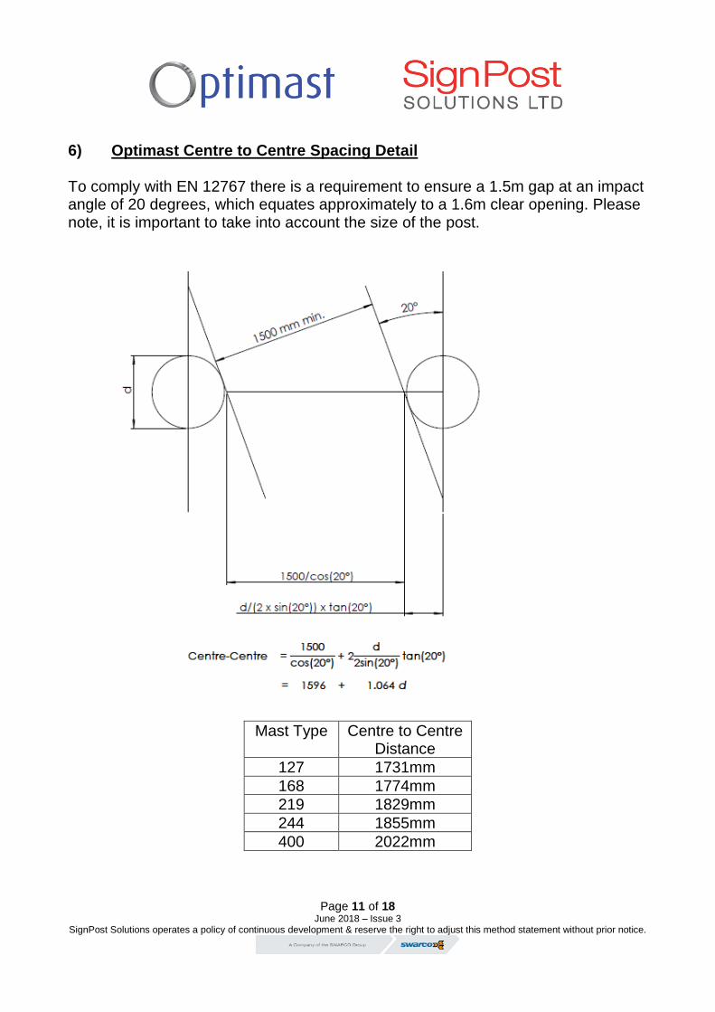
6) Optimast Centre to Centre Spacing Detail
To comply with EN 12767 there is a requirement to ensure a 1.5m gap at an impact angle of 20 degrees, which equates approximately to a 1.6m clear opening. Please note, it is important to take into account the size of the post.
Mast Type Centre to Centre Distance
127 1731mm
168 1774mm
219 1829mm
244 1855mm
400 2022mm

Page 12 of 18
June 2018 – Issue 3 SignPost Solutions operates a policy of continuous development & reserve the right to adjust this method statement without prior notice.
7) Installation Method Statement 7a) Anchor Cradle Installation in Concrete Foundations Drawing 14001-3 Optimast 127
Drawing 14002-2 Optimast 168
Drawing 14002-3 Optimast 219
Drawing 14003-2 Optimast 244
Drawing 14004-2 Optimast 400
Optimast sign masts are usually installed on concrete foundations using Signpost Solutions cast in anchor cradles. Foundation design dimensions will usually be given at quote stage however; the final foundation dimensions are the responsibility of the independent scheme designer. Optimast sign mast anchor cradles are often installed in un-reinforced concrete foundations. However, steel reinforcement may be used if the designer deems it necessary to provide the required strength or to comply with the highway authority design specifications. Signpost Solutions recommends a minimum concrete grade of 25N/mm² (BS 8500 ST5). However, the final design is the responsibility of the scheme designer. 1. Excavate the Hole/Trench
Using suitable equipment, excavate the hole/trench to the dimensions specified by the independent scheme designer.

Page 13 of 18
June 2018 – Issue 3 SignPost Solutions operates a policy of continuous development & reserve the right to adjust this method statement without prior notice.
2. Secure Anchor Cradle
The anchor cradle must be securely suspended in the foundation in its final position. Level and align prior to concreting the foundation. This is usually achieved by nailing or screwing the template board to timbers spanning across the excavation or the foundation shuttering. The underside of the removable template board is to be set to the top of concrete level. The template board should be checked with a spirit level to ensure it is level and the arrangement checked to ensure it is robust and rigid before concreting.
3. Pour Concrete
Anchorages and baseplates of the masts should be exposed and not buried under soil. The top of the concrete foundation should be level or not more than 50mm above the surrounding ground or paving to prevent the underside of errant vehicles catching on the concrete before hitting the sign mast in a vehicle impact. The concrete must be mechanically vibrated to ensure that all air pockets and voids are eliminated from the foundation concrete.
4. Immediately after concreting the bolt position and alignment should be re-
checked to ensure the anchor has not moved.
5. The templates may be removed the day after concreting but the

Page 14 of 18
June 2018 – Issue 3 SignPost Solutions operates a policy of continuous development & reserve the right to adjust this method statement without prior notice.
temporary/disposable bolts should then be replaced to protect the anchor socket threads until the sign mast can be erected.
Masts and sign plates should not be erected until the contractor is satisfied the
concrete has reached a cube strength of 17.5 N/mm2. To erect masts earlier after concreting, stronger concrete can be used to shorten the time needed to achieve the 17.5 N/ mm2 cube strength.
7b) Erection of Optimast on their Anchor Cradles
Masts and sign plates should not be erected until the concrete has reached a cube strength of 17.5 N/mm2.
Torque wrench setting for foundation bolt sets:
Optimast
type
Foundation stud size
and material
Torque applied to third nut
Nm
Torque applied
fourth nut Nm
127
M16 A4-80
187
94
168 & 219
M20 A4-80
364
182
244 & 400
M24 A4-80
629
315
1. Remove any debris from around the anchor and check the concrete for high
spots that may prevent the mast from seating correctly on the bolts.
2. Remove and dispose of the temporary/disposable bolts and the template
board.
3. Grease anchor studs and the internal threads of the anchorage sockets
threads with Rocol anti-seize stainless lubricant or similar.
4. Screw the 4 studs by hand into the anchor socket as per table below.

Page 15 of 18
June 2018 – Issue 3 SignPost Solutions operates a policy of continuous development & reserve the right to adjust this method statement without prior notice.
Bolt insertion depths:
Mast Type Drawing Length in socket
127 14001-3 32mm
168 14002-2 40mm
219 14002-3 40mm
244 14003-2 48mm
400 14004-2 48mm
Check the resultant height of the top of the studs above the sockets as per table below.
Maximum height of exposed thread:
Mast Type Drawing Exposed thread length
127 14001-3 104mm
168 14002-2 116mm
219 14002-3 116mm
244 14003-2 137mm
400 14004-2 137mm
5. Screw one stainless steel nut down each stud until they lock tight onto each
socket in the concrete. Tighten each nut with a spanner but do not apply excess torque, this will prevent the stud from turning during subsequent operations.
6. Screw a second stainless nut down onto each stud until they are all
approximately 3 mm above the first nut. Check across all four second stainless nuts with a spirit level and adjust by screwing up or down until all four nuts are precisely level to create a level bed for the mast base plate.
7. Apply to each stud a stainless steel washer.

Page 16 of 18
June 2018 – Issue 3 SignPost Solutions operates a policy of continuous development & reserve the right to adjust this method statement without prior notice.
8. Lower the mast onto the studs, taking care not to damage the threads.
Please note, our Optimast 400 has two flat sides. Please ensure the flat side is facing oncoming traffic. The baseplate is provided with slotted holes to assist with alignment when being installed.
9. Apply a stainless steel washer to each stud, then a third stainless nut and
hand-tighten. Check the base plate is fully seated on all four studs and the
mast is vertical. If not, slacken off third stainless nuts and adjust the nuts under
the baseplate. Hand-tighten the nuts on top again and re-check.
10. When you are satisfied that the mast is vertical and fully seated, tighten the
third stainless nut to the recommended torque using a torque wrench, see
above table for torque settings. The nuts below the baseplate should be
checked to ensure they do not rotate and if necessary an open ended spanner
should be used to prevent any rotation.
11. Apply a fourth stainless steel nut to each stud and tighten to the torque
recommended using a torque wrench, see above table for torque settings.
12. Screw the first stainless nut touching the concrete/socket up against the
second stainless nut under the base plate and firmly tighten with an open
ended spanner.
13. Check the mast is vertical using a suitable measuring device.
7c) Sign Installation
The supplied Optimast Clamps with rubber, nuts bolts and washers are to be used when erecting the sign. If ‘Interlocking’ Channels are used on the rear of the sign assembly, Optimast Clamps are to be used on the “Lower” channel position of any joint. For connection of the “Upper” channel to its mating section, Butting Plates are to be used. When the sign is mounted in the current position, the supplied bolts are to be tightened to the correct torque settings of 18 Nm. (18Nm refers to Signfix Channel – please refer to other manufacturers guidelines if alternative channel is used). We advise threads to be lubricated with Rocal anti-seize stainless lubricant or similar.

Page 17 of 18
June 2018 – Issue 3 SignPost Solutions operates a policy of continuous development & reserve the right to adjust this method statement without prior notice.
7d) Routine inspections:
1. It is recommended that a general inspection of the passive mast is carried out by a competent person during routine maintenance and inspections of the sign plates.
2. The following items should be reviewed as part of the inspections:
• Absence or looseness of nuts or bolts.
• Accumulation of debris or dirt around baseplates

Page 18 of 18
June 2018 – Issue 3 SignPost Solutions operates a policy of continuous development & reserve the right to adjust this method statement without prior notice.
7e) Accident Damage inspection: Depending on the level of impact, the following items should be reviewed as
part of the inspection:
• Absence or looseness of nuts or bolts.
• Accumulation of debris or dirt around baseplates
• Fracture/buckling of the mast material
• If the mast is partially or completely detached, care is to be taken when handling material with sharp or serrated edges.
• In all instances it is recommended that new nuts, studs and washers are fitted with any new mast installation.
Signpost Solutions Ltd, Unit 5, Clarendon Drive, The Parkway, Tipton, DY4 0QA
www.signfix.co.uk