optimity 3-phase induction motors · 2017-11-30 · synchronous motor with drive ip23/55 0.75 –...
TRANSCRIPT
IE2&IE3Frame Size 80-355
Power Rating 0.37-355Kw
OptIMity 3-phase induction motors

DC DrivesMentor MPServo Drives
Digitax STM
High Speed MotorsCPLS
High performance DC drive
25 -7,400A
Intelligent, compact and dynamic servo drive range
0.72– 19.3 Nm200V, 400V
High Speed InductionMotorsDC replacement
Up to 10000rpm7.5-550kW
ManufacturingConstruction & Infrastructure
Construction & Infrastructure Manufacturing
Drives & Motors TechnologyCore Offering in Asia Pacific
Dri
ves
AC DrivesPowerdrive MD2 & F300
AC & Servo DrivesUnidrive M
sekarB
dna sr
oto
M
Permanent Magnet MotorsDyneo range
Liquid Cooled MotorsIMfinity LC
Normal Duty MotorsOptIMity
Flexible and energy efficiency drive family
1.1kW – 2.8MW
Drive models to optimizeproductivity, across multitude of automation applications
0.25kW – 2.8MW
Premium Efficiency Permanent Magnet Synchronous Motor with drive
IP23/550.75 – 500kW
3 phase motorsIP55, Cast Iron & Aluminum For General Industry
0.37 to 355 kW
Liquid-Cooled Induction Motors for extreme environments, compactness and noise reduction150 - 1500 kWIP 56
Process
Process
Heavy Duty Motors + BrakesFLSMV + FCPL
Servo MotorsUnimotor fm and hd
3-phase motors IP55/65Optimized for VS applications with optional encoder and High performance Brake
11- 400kW75 - 1500 Nm
Dynamic performance ACbrushless
0.72-136 Nm(408 Nm peak)
Open Type MotorsPLS
3 phase motors IP23, with Aluminum or Steel housing
55 to 900 kW

4 Leroy-Somer - OptIMity 3-phase induction motors - 5472 en – 2017.03 / b
OptIMity 3-phase induction motors
Contents
OVERVIEW .........................................................................5
GENERAL INFORMATION
INTERNATIONAL AND NATIONAL STANDARD EQUIVALENTS
CONSTRUCTION
Mountings and Positions ......................................................... 7
Cooling .................................................................................. 8
Terminal Box ........................................................................... 8
Wiring Diagram ...................................................................... 8
Earth Terminal ........................................................................ 8
Bearing ................................................................................... 9
Operation ............................................................................... 9
OPERATION
Supply Voltage ...................................................................... 10
Overload Capacity ................................................................. 10
Insulation System .................................................................. 10
Vibration ............................................................................... 11
Thermal Protection ................................................................ 11
Anti-condensation Protection ................................................ 11
Starting Method .................................................................... 12
DESCRIPTION
Product Code ........................................................................ 16
Nameplate ............................................................................ 16
ELECTRICAL AND MECHANICAL CHARACTERISTICS .. 17
ELECTRICAL AND MECHANICAL DATA
ELECTRICAL AND MECHANICAL DATA IE2 ............................... 17
ELECTRICAL AND MECHANICAL DATA IE3 .............................. 19
DIMENSION ...................................................................... 21
OPTA
IM 1001 (IM B3) ..................................................................... 21
IM 3001 (IM B5) ..................................................................... 22
IM 2001 (IM B35) ................................................................... 23
OPT
IM 1001 (IM B3) ...................................................................... 24
IM 3001 (IM B5) ..................................................................... 25
IM 2001 (IM B35) ................................................................... 26
APPENDIX ......................................................................... 27
Standard formulae used in electrical engineering ................... 27
Tolerance on main performance parameters .......................... 29

5
OptIMity 3-phase induction motors
Overview
Leroy-Somer - OptIMity 3-phase induction motors - 5472 en – 2017.03 / b
Leroy Somer OptIMity series general industries TEFC 3 phase asynchronous motors with efficiency level IE2&IE3. These motors have been designed to incorporate the latest IEC and European standards, and can satisfy most of industry's demands.
OptIMity is designed for DOL operation with continuous duty (S1).
OptIMity Standard Features• Aluminum frame(SH<=160)and cast iron frame• Standard painting color reference RAL6000• Supply voltage 400V,frequency 50Hz• The permitted tolerance of the voltage is ±5%• Efficiency level IE2&IE3• Standard mounting construction according to IEC 60034-7: IMB3, IM B5, IM B35 and etc• Top position of main terminal• Regreasing device (SH>=250 as standard, SH160-225 as option)• Cooling method IC411• Enclosure protection IP55• Insulation/Thermal class F/B• Vibration A• Plastic cable gland
OptIMity Options• Space heater• Special painting color• Special voltage• Insulation class H• Thermal protection PTC and PT100• Double shaft end/Special shaft end• SKF/FAG bearing• Regreasing device• Metal fan• Drip cover• Main terminal box position(RH or LH)• External earthing bolt• Type test• Cable glands - Brass - Stainless steel
General Information
Environmental• Ambient temperature:-15℃~ 40℃• Altitude less than 1000 m• Humidity ≤90%For higher ambient temperatures and / or site altitudes higher than 1000 m above sea level, the motor should be derated. Please consult Leroy-Somer.
6
OptIMity 3-phase induction motors
Overview
Leroy-Somer - OptIMity 3-phase induction motors - 5472 en – 2017.03 / b
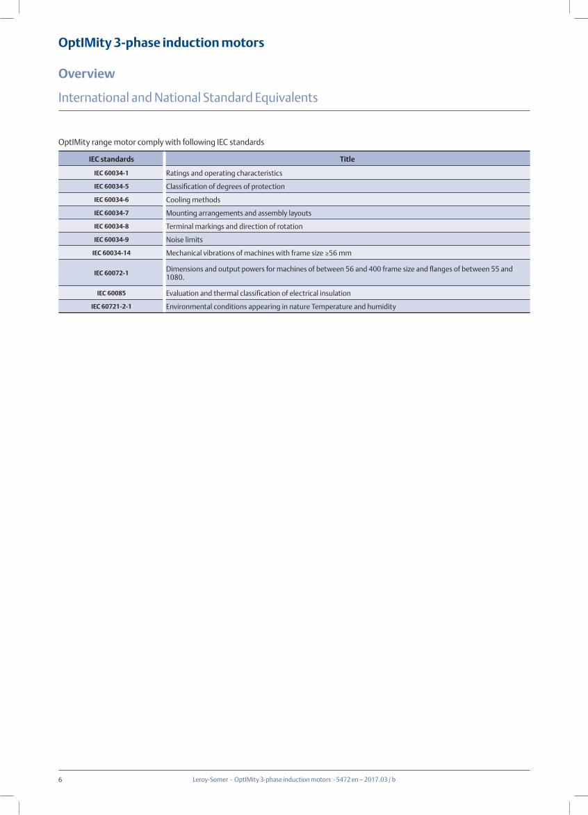
OptIMity range motor comply with following IEC standards
International and National Standard Equivalents
IEC standards Title
IEC 60034-1 Ratings and operating characteristics
IEC 60034-5 Classification of degrees of protection
IEC 60034-6 Cooling methods
IEC 60034-7 Mounting arrangements and assembly layouts
IEC 60034-8 Terminal markings and direction of rotation
IEC 60034-9 Noise limits
IEC 60034-14 Mechanical vibrations of machines with frame size ≥56 mm
IEC 60072-1 Dimensions and output powers for machines of between 56 and 400 frame size and flanges of between 55 and 1080.
IEC 60085 Evaluation and thermal classification of electrical insulation
IEC 60721-2-1 Environmental conditions appearing in nature Temperature and humidity

7
OptIMity 3-phase induction motors
Overview
Leroy-Somer - OptIMity 3-phase induction motors - 5472 en – 2017.03 / b
Construction Type Foot mounted motors
Mounting Type IMB3 IMB6 IMB7 IMB8 IMV5 IMV6
Diagram
Construction Type (FF) Flange mounted motors
Mounting Type IMB5 IMV1 IMV3 IMB35 IMV15 IMV36
Diagram
Construction Type (FT) Face mounted motors
Mounting Type IMB14 IMB18 IMB34
Diagram
Frame Size
Foot mounted motors Secondary Mounting
B3 B5 B35 V1 V3 V5 V6 B6 B7 B8 V15 V36 B14 B34 V18
80-112 √ √ √ √ √ √ √ √ √ √ √ √ √ √ √
132-160 √ √ √ √ √ √ √ √ √ √ √ √ - - -
180-280 √ √ √ √ - - - - - - - - - - -
315-355 √ - √ √ - - - - - - - - - - -
√available, -not available
Construction
Mountings and Positions

8
OptIMity 3-phase induction motors
Overview
Leroy-Somer - OptIMity 3-phase induction motors - 5472 en – 2017.03 / b
Construction
THREE-PHASE MOTOR1 SPEED-2VOLTAGES L1 - L2 - L3
W2 U2 V2
L1 L2 L3
U1 V1 W1
W2 U2 V2
L1 L2 L3
U1 V1 W1
2
4
13
A
BD
Standardposition
Positions of cable entry in relation to thedrive end
Positions 2 not recommended(impossible on standard(FF)
flange mounted motor)
Standardpositionon delivery(can be turned)
A
BD
Standardposition
Positions of the terminal box in relation
to the drive end (motor in IM 1001
position)
Cooling
Standard cooling method is self-ventilation motors with radial-flow fans (IC411 according to IEC 60034-6).
Terminal BoxPlaced as standard on the top of the motor near the drive end, it is IP 55 protection and fitted with plastic cable glands.
Frame Size Cable Gland Size Cable Gland Qty.
80
M24x1.5 190
100
112M30x2 2
132
160M36x2 2
180
200M48x2 2
225
250
M64x2 2280
315
355 M72x2 2
The standard position of cable entry is on the right, seen from the drive end but, owing to the symmetrical construction of the box, it can usually be placed in any of the 4 directions as below picture:
If required, the terminal box may be fitted right or left side of the motor(seen from the drive end).
Wiring DiagramAll standard motors are supplied with a wiring diagram in the terminal box.
Earth TerminalThis is situated inside the terminal box. Consisting of a threaded stud with a hexagonal nut, it is used to connect cables with cross-sections at least as large as the cross-section of the phase conductors.It is indicated by the sign: ( ) in the terminal box. On request, a second earth terminal can be fitted on one or both of the feet.

9
OptIMity 3-phase induction motors
Overview
Leroy-Somer - OptIMity 3-phase induction motors - 5472 en – 2017.03 / b
Construction
Bearing assignment as below table:
Bearing
OptIMity series motors are equipped with the ball bearing as standard (sealed type or regreasable type).
For frame size 80-225mm sealed bearing as standard. For frame size 250-355mm regreasable bearing as standard, with regrease devise.
If required, frame size 160-225mm regreasable bearing and regrease device as option.
Type DE NDEOPT/OPTA-80 6204-2RZ 6204-2RZOPT/OPTA-90 6205-2RZ 6205-2RZ
OPT/OPTA-100 6206-2RZ 6206-2RZOPT/OPTA-112 6206-2RZ 6206-2RZ
OPTA-132 6308-2RZ 6308-2RZOPTA-160 6309-2RZ 6209-2RZOPT-132 6208-2RZ 6208-2RZOPT-160 6309-2RZ 6309-2RZOPT-180 6311-2RZ 6311-2RZOPT-200 6312-2RZ 6312-2RZOPT-225 6313-2RZ 6312-2RZ
OPT-250-2 6313 6313OPT-250-4,6 6314 6313
OPT-280-2 6314 6314OPT-280-4,6 6317 6314
OPT-315-2 6317 6317OPT-315-4,6 NU319 6319
OPT-355-2 6318 6316OPT-355-4,6 6322 6316
Frame Size Quantity of Grease(g)Re-greasing Interval(h)
3000(r/min) 1500(r/min) 1000(r/min)
160,180 20 4200 7000 9000
200,225 25 3100 6500 8500
250,280 35 2000 6000 8000
315 50 2000 5500 7500
355 60 3700(35g) 8300 13800
Bearing Re-greasing
Re-greasing interval and quantity of grease as below table:
10
OptIMity 3-phase induction motors
Overview
Leroy-Somer - OptIMity 3-phase induction motors - 5472 en – 2017.03 / b
Operation
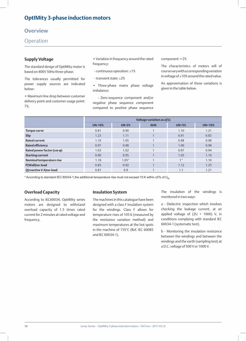
Overload Capacity
According to IEC60034, OptIMity series motors are designed to withstand overload capacity of 1.5 times rated current for 2 minutes at rated voltage and frequency.
Insulation System
The machines in this catalogue have been designed with a class F insulation system for the windings. Class F allows for temperature rises of 105 K (measured by the resistance variation method) and maximum temperatures at the hot spots in the machine of 155°C (Ref. IEC 60085 and IEC 60034-1).
Voltage variation as a(%)
UN-10% UN-5% 0UN UN+5% UN+10%
Torque curve 0.81 0.90 1 1.10 1.21
Slip 1.23 1.11 1 0.91 0.83
Rated current 1.10 1.05 1 0.98 0.98
Rated efficiency 0.97 0.98 1 1.00 0.98
Rated power factor (cos φ) 1.03 1.02 1 0.97 0.94
Starting current 0.90 0.95 1 1.05 1.10
Nominal temperature rise 1.18 1.05* 1 1* 1.10
P(Wall)no-load 0.85 0.92 1 1.12 1.25
Q(reactive V A)no-load 0.81 0.9 1 1.1 1.21
* According to standard IEC 60034-1,the additional temperature rise must not exceed 10 K within ±5% of UN.
The insulation of the windings is monitored in two ways:
a - Dielectric inspection which involves checking the leakage current, at an applied voltage of (2U + 1000) V, in conditions complying with standard IEC 60034-1 (systematic test).
b - Monitoring the insulation resistance between the windings and between the windings and the earth (sampling test) at a D.C. voltage of 500 V or 1000 V.
Supply Voltage
The standard design of OptIMity motor is based on 400V 50Hz three-phase.
The tolerances usually permitted for power supply sources are indicated below:
• Maximum line drop between customer delivery point and customer usage point: 7%.
• Variation in frequency around the rated frequency:
- continuous operation: ±1%
- transient state: ±2%
• Three-phase mains phase voltage imbalance:
- Zero-sequence component and/or negative phase sequence component compared to positive phase sequence
component: < 2%
The characteristics of motors will of course vary with a corresponding variation in voltage of ±10% around the rated value.
An approximation of these variations is given in the table below.

11
OptIMity 3-phase induction motors
Overview
Leroy-Somer - OptIMity 3-phase induction motors - 5472 en – 2017.03 / b
Operation
Vibration
OptIMity rotors are balanced to severity grade A with half key. The effective vibration values for unloaded motors as table below(Free suspension).
Vibration Level
Frame Size H(mm)
56 ≤ H ≤ 132 132 < H ≤ 280 H > 280
Displacementµm
Speed mm/s
Accelerationm/s2
Displacementµm
Speedmm/s
Accelerationm/s2
Displacementµm
Speed mm/s
Accelerationm/s2
A 25 1.6 2.5 35 2.2 3.5 45 2.8 4.4
Buit-in Indirect Thermal Protection
Type Operating principle Operating curveBreaking
capacity(A)Protection provided
MountingNumber of devices*
Positive temperaturecoeffcient thermistor
PTC
Non-linear variableresistor,infdirectly heated
R
T0
General monitoringfor transient overloads
Mounted with associated relayin control circuit
3 in series
Platinum temperatureseneorPT 100
Linear variable resistor indirectly heated
R
T
0High accuracy continuous
surveillance of key hot spots
Mounted in control boards with associated reading equipment
(or recorder)
1 per hot spot
- NRT:nominal running temperature- The NRTs are chosen according to the position of the sensor in the motor and the temperature rise class.
* The number of devices relates to the winding protection.
Fitting Thermal Protection- PTC,with relay, in the control circuits- PT 100,with reading equipment or recorder, in the installation control panel for continuous surveillance
Alarm and Early WarningAll protective equipment can be backed up by another type of protection (with different NRTs): the first device will then act as an early warning (light or sound signals given without shutting down the power circuits), and the second device will be the alarm (shutting down the power circuits)
Bearing ProtectionOptIMity motors bearing has no protection as standard. The bearing is recommended to be protected for some severe application. The bearing is protected through thermometers screwed into the bearing plates of motor driven end (DE) and non-drive-end (NDE). The wires are routed through the main connection box.
Anti-condensation ProtectionMotors whose windings are at risk of condensation due to the climatic conditions, e.g. inactive motors in humid atmospheres or motors that are subjected to widely fluctuating temperatures can be equipped with anti-condensation heaters.
Thermal Protection
Motors are protected by a manual or automatic overcurrent relay, placed between the isolating switch and the motor. This relay may in turn be protected by fuses. These protection devices provide total protection of the motor against non-
transient overloads. If a shorter reaction time is required, if you want to detect transient overloads, or if you wish to monitor temperature rises at "hot spots" in the motor or at strategic points in the installation for maintenance purposes, it would be advisable to install heat sensors
at sensitive points. The various types are shown in the table below, with a description of each. It must be emphasized that under no circumstances can these sensors be used to carry out direct regulation of the motor operating cycles.
12
OptIMity 3-phase induction motors
Overview
Leroy-Somer - OptIMity 3-phase induction motors - 5472 en – 2017.03 / b
Operation
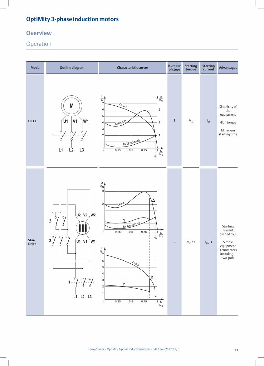
Starting MethodThe two essential parameters for starting cage induction motors are:- starting torque- starting currentThese two parameters and the resistive torque determine the starting time.These three characteristics arise from the construction of cage induction motors. Depending on the driven load, it may be necessary to adjust these values to avoid torque surges on the load or current surges in the supply. There are essentially five different types of supply, which are:- D.O.L. starting- star/delta starting- soft starting with auto-transformer- soft starting with resistors- electronic startingThe tables on the next few pages give the electrical outline diagrams, the effect on the characteristic curves, and a comparison of the respective advantages of each mode.
Motors with Associated Electronics
Electronic starting modes control the voltage at the motor terminals throughout the entire starting phase, giving very gradual smooth starting.
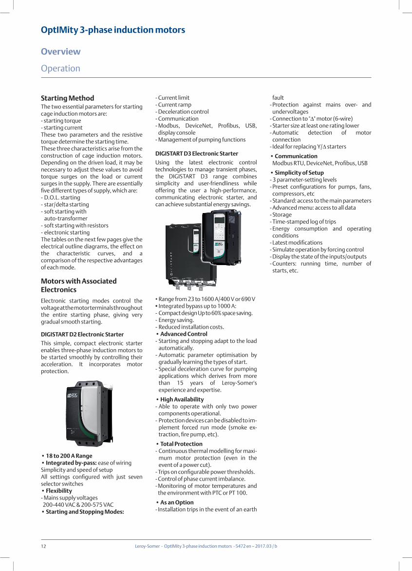
DIGISTART D2 Electronic Starter
This simple, compact electronic starter enables three-phase induction motors to be started smoothly by controlling their acceleration. It incorporates motor protection.
• 18 to 200 A Range• Integrated by-pass: ease of wiringSimplicity and speed of setupAll settings configured with just seven selector switches• Flexibility- Mains supply voltages 200-440 VAC & 200-575 VAC• Starting and Stopping Modes:
- Current limit- Current ramp- Deceleration control- Communication- Modbus, DeviceNet, Profibus, USB,
display console- Management of pumping functions
DIGISTART D3 Electronic Starter
Using the latest electronic control technologies to manage transient phases, the DIGISTART D3 range combines simplicity and user-friendliness while offering the user a high-performance, communicating electronic starter, and can achieve substantial energy savings.
• Range from 23 to 1600 A/400 V or 690 V• Integrated bypass up to 1000 A:- Compact design Up to 60% space saving.- Energy saving.- Reduced installation costs.• Advanced Control- Starting and stopping adapt to the load
automatically.- Automatic parameter optimisation by
gradually learning the types of start.- Special deceleration curve for pumping
applications which derives from more than 15 years of Leroy-Somer's experience and expertise.
• High Availability- Able to operate with only two power
components operational.- Protection devices can be disabled to im-
plement forced run mode (smoke ex-traction, fire pump, etc).
• Total Protection- Continuous thermal modelling for maxi-
mum motor protection (even in the event of a power cut).
- Trips on configurable power thresholds.- Control of phase current imbalance.- Monitoring of motor temperatures and
the environment with PTC or PT 100.
• As an Option- Installation trips in the event of an earth
fault- Protection against mains over- and
undervoltages- Connection to "Δ" motor (6-wire)- Starter size at least one rating lower- Automatic detection of motor
connection- Ideal for replacing Y/Δ starters
• Communication Modbus RTU, DeviceNet, Profibus, USB
• Simplicity of Setup- 3 parameter-setting levels- Preset configurations for pumps, fans,
compressors, etc- Standard: access to the main parameters- Advanced menu: access to all data- Storage- Time-stamped log of trips- Energy consumption and operating
conditions- Latest modifications- Simulate operation by forcing control- Display the state of the inputs/outputs- Counters: running time, number of
starts, etc.
13
OptIMity 3-phase induction motors
Overview
Leroy-Somer - OptIMity 3-phase induction motors - 5472 en – 2017.03 / b
Operation
Mode Outline diagram Characteristic curves Number of steps
Starting torque
Starting current Advantages
D.O.L. 1 MD ID
Simplicity of the
equipment
High torque
Minimum starting time
Star- Delta 2 MD / 3 ID / 3
Starting current
divided by 3
Simple equipment
3 contactors including 1 two-pole
L3L2L1
W1V1U1
M
1
L3L2L1
W1V1U1
1
3
W2V2U2
M_MN
N_Ns
0.25 0.5 0.75 1
1
2
3
I_IN
2
4
6
1
3
5
7
0
M (Motor)
Direct
Mr (Resistive)
M_MN
N_Ns
0.25 0.5 0.75 1
1
2
3
0
Direct
Mr (Resistive) Y
N_Ns
0.25 0.5 0.75 1
I_IN
2
4
6
1
3
5
7
0
Y
Direct
NN
2
NN
14
OptIMity 3-phase induction motors
Overview
Leroy-Somer - OptIMity 3-phase induction motors - 5472 en – 2017.03 / b
Operation
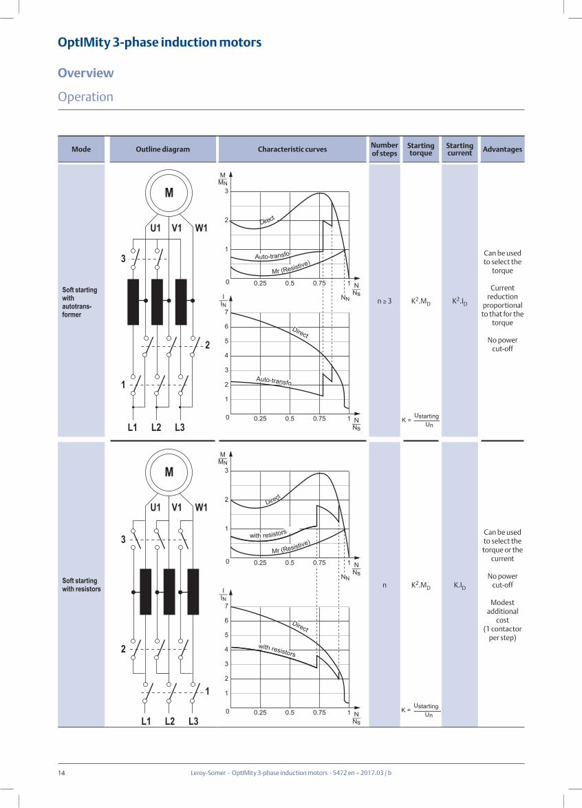
Mode Outline diagram Characteristic curves Number of steps
Starting torque
Starting current Advantages
Soft starting with autotrans-former
n ≥ 3 K2.MD K2.ID
Can be used to select the
torque
Current reduction
proportional to that for the
torque
No power cut-off
Soft starting with resistors n K2.MD K.ID
Can be used to select the torque or the
current
No power cut-off
Modest additional
cost(1 contactor
per step)
K =Ustarting
Un
K =Ustarting
Un
W1V1U1
M
2
L3L2L1
1
3
W1V1U1
1
L3L2L1
2
3
M
M_MN
N_Ns
0.25 0.5 1
1
2
3
0
Direct
Mr (Resistive)
N_Ns
0.25 0.5 0.75 1
I_IN
2
4
6
1
3
5
7
0
Auto-transfo
Auto-transfo
Direct
M_MN
N_Ns
0.25 0.5 1
1
2
3
0Mr (Resistive)
N_Ns
0.25 0.5 0.75 1
I_IN
2
4
6
1
3
5
7
0
Direct
with resistors
Direct
with resistors
0.75
0.75
NN
NN
15
OptIMity 3-phase induction motors
Overview
Leroy-Somer - OptIMity 3-phase induction motors - 5472 en – 2017.03 / b
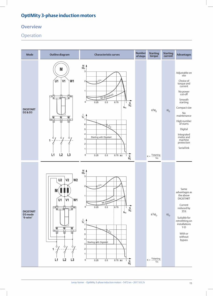
Mode Outline diagram Characteristic curves Number of steps
Starting torque
Starting current Advantages
DIGISTARTD2 & D3
K2MD KID
Adjustable on site
Choice of torque and
current
No power cut-off
Smooth starting
Compact size
No maintenance
High number of starts
Digital
Integrated motor and machine
protection
Serial link
DIGISTARTD3 mode"6-wire"
K2MD KID
Same advantages as
the above DIGISTART
Current reduced by
35%
Suitable for retrofitting on
installations Y-D
With or without bypass
K =Ustarting
Un
K =Ustarting
Un
D.O.L.
D.O.L.
Mr (Resistive)
Mr (Resistive)
D.O.L.
D.O.L.
Starting with Digistart
Starting with Digistart
Operation
16
OptIMity 3-phase induction motors
Overview
Leroy-Somer - OptIMity 3-phase induction motors - 5472 en – 2017.03 / b
Description
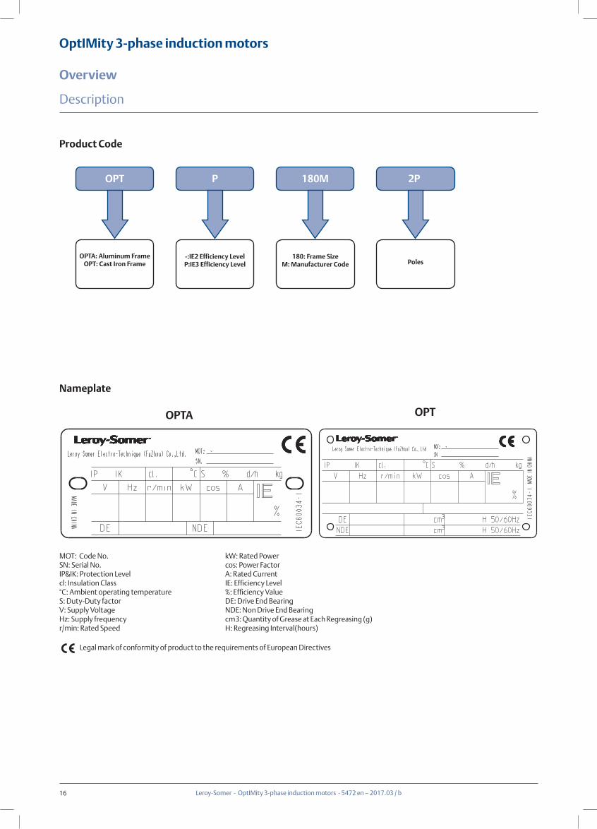
Product Code
Nameplate
OPT
OPTA: Aluminum FrameOPT: Cast Iron Frame
180M
180: Frame SizeM: Manufacturer Code
2P
Poles
P
-:IE2 Efficiency LevelP:IE3 Efficiency Level
MOT: Code No.SN: Serial No.IP&IK: Protection Levelcl: Insulation Class°C: Ambient operating temperatureS: Duty-Duty factorV: Supply VoltageHz: Supply frequencyr/min: Rated Speed
Legal mark of conformity of product to the requirements of European Directives
kW: Rated Powercos: Power FactorA: Rated CurrentIE: Efficiency Level %: Efficiency ValueDE: Drive End BearingNDE: Non Drive End Bearingcm3: Quantity of Grease at Each Regreasing (g)H: Regreasing Interval(hours)
OPTA OPT
17
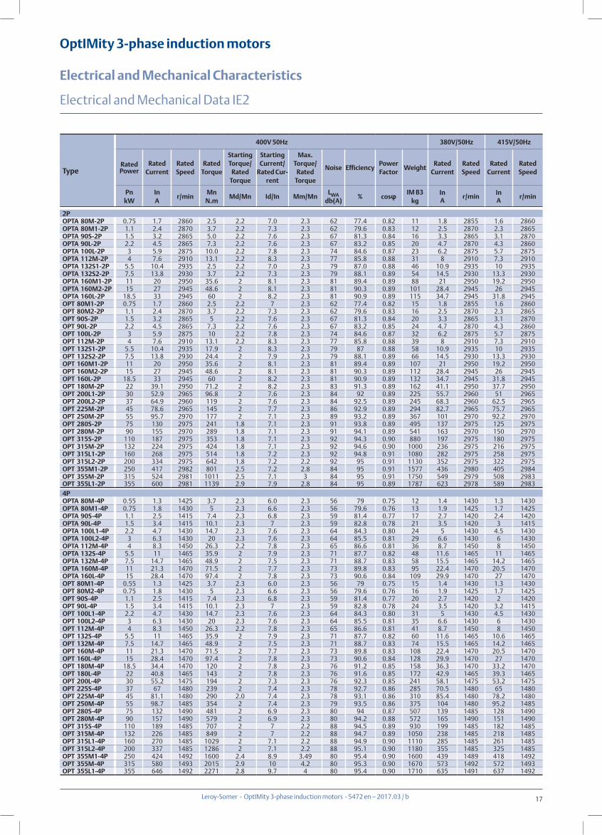
OptIMity 3-phase induction motors
Electrical and Mechanical Characteristics
Leroy-Somer - OptIMity 3-phase induction motors - 5472 en – 2017.03 / b
Electrical and Mechanical Data IE2
2POPTA 80M-2P 0.75 1.7 2860 2.5 2.2 7.0 2.3 62 77.4 0.82 11 1.8 2855 1.6 2860OPTA 80M1-2P 1.1 2.4 2870 3.7 2.2 7.3 2.3 62 79.6 0.83 12 2.5 2870 2.3 2865OPTA 90S-2P 1.5 3.2 2865 5.0 2.2 7.6 2.3 67 81.3 0.84 16 3.3 2865 3.1 2870OPTA 90L-2P 2.2 4.5 2865 7.3 2.2 7.6 2.3 67 83.2 0.85 20 4.7 2870 4.3 2860OPTA 100L-2P 3 5.9 2875 10.0 2.2 7.8 2.3 74 84.6 0.87 23 6.2 2875 5.7 2875OPTA 112M-2P 4 7.6 2910 13.1 2.2 8.3 2.3 77 85.8 0.88 31 8 2910 7.3 2910OPTA 132S1-2P 5.5 10.4 2935 2.5 2.2 7.0 2.3 79 87.0 0.88 46 10.9 2935 10 2935OPTA 132S2-2P 7.5 13.8 2930 3.7 2.2 7.3 2.3 79 88.1 0.89 54 14.5 2930 13.3 2930OPTA 160M1-2P 11 20 2950 35.6 2 8.1 2.3 81 89.4 0.89 88 21 2950 19.2 2950OPTA 160M2-2P 15 27 2945 48.6 2 8.1 2.3 81 90.3 0.89 101 28.4 2945 26 2945OPTA 160L-2P 18.5 33 2945 60 2 8.2 2.3 81 90.9 0.89 115 34.7 2945 31.8 2945OPT 80M1-2P 0.75 1.7 2860 2.5 2.2 7 2.3 62 77.4 0.82 15 1.8 2855 1.6 2860OPT 80M2-2P 1.1 2.4 2870 3.7 2.2 7.3 2.3 62 79.6 0.83 16 2.5 2870 2.3 2865OPT 90S-2P 1.5 3.2 2865 5 2.2 7.6 2.3 67 81.3 0.84 20 3.3 2865 3.1 2870OPT 90L-2P 2.2 4.5 2865 7.3 2.2 7.6 2.3 67 83.2 0.85 24 4.7 2870 4.3 2860OPT 100L-2P 3 5.9 2875 10 2.2 7.8 2.3 74 84.6 0.87 32 6.2 2875 5.7 2875OPT 112M-2P 4 7.6 2910 13.1 2.2 8.3 2.3 77 85.8 0.88 39 8 2910 7.3 2910OPT 132S1-2P 5.5 10.4 2935 17.9 2 8.3 2.3 79 87 0.88 58 10.9 2935 10 2935OPT 132S2-2P 7.5 13.8 2930 24.4 2 7.9 2.3 79 88.1 0.89 66 14.5 2930 13.3 2930OPT 160M1-2P 11 20 2950 35.6 2 8.1 2.3 81 89.4 0.89 107 21 2950 19.2 2950OPT 160M2-2P 15 27 2945 48.6 2 8.1 2.3 81 90.3 0.89 112 28.4 2945 26 2945OPT 160L-2P 18.5 33 2945 60 2 8.2 2.3 81 90.9 0.89 132 34.7 2945 31.8 2945OPT 180M-2P 22 39.1 2950 71.2 2 8.2 2.3 83 91.3 0.89 162 41.1 2950 37.7 2950OPT 200L1-2P 30 52.9 2965 96.8 2 7.6 2.3 84 92 0.89 225 55.7 2960 51 2965OPT 200L2-2P 37 64.9 2960 119 2 7.6 2.3 84 92.5 0.89 245 68.3 2960 62.5 2965OPT 225M-2P 45 78.6 2965 145 2 7.7 2.3 86 92.9 0.89 294 82.7 2965 75.7 2965OPT 250M-2P 55 95.7 2970 177 2 7.1 2.3 89 93.2 0.89 367 101 2970 92.2 2970OPT 280S-2P 75 130 2975 241 1.8 7.1 2.3 91 93.8 0.89 495 137 2975 125 2975OPT 280M-2P 90 155 2970 289 1.8 7.1 2.3 91 94.1 0.89 541 163 2970 150 2970OPT 315S-2P 110 187 2975 353 1.8 7.1 2.3 92 94.3 0.90 880 197 2975 180 2975OPT 315M-2P 132 224 2975 424 1.8 7.1 2.3 92 94.6 0.90 1000 236 2975 216 2975OPT 315L1-2P 160 268 2975 514 1.8 7.2 2.3 92 94.8 0.91 1080 282 2975 258 2975OPT 315L2-2P 200 334 2975 642 1.8 7.2 2.2 92 95 0.91 1130 352 2975 322 2975OPT 355M1-2P 250 417 2982 801 2.5 7.2 2.8 84 95 0.91 1577 436 2980 405 2984OPT 355M-2P 315 524 2981 1011 2.5 7.1 3 84 95 0.91 1750 549 2979 508 2983OPT 355L1-2P 355 600 2981 1139 2.9 7.9 2.8 84 95 0.89 1787 623 2978 589 2983
Type
400V 50Hz 380V/50Hz 415V/50Hz
Rated Power
Rated Current
Rated Speed
Rated Torque
Starting Torque/
Rated Torque
Starting Current/
Rated Cur-rent
Max. Torque/
Rated Torque
Noise EfficiencyPower Factor
WeightRated
CurrentRated Speed
Rated Current
Rated Speed
PnkW
InA
r/minMn
N.mMd/Mn Id/In Mm/Mn
LWAdb(A)
% cosφ IM B3kg
InA
r/minInA
r/min
4POPTA 80M-4P 0.55 1.3 1425 3.7 2.3 6.0 2.3 56 79 0.75 12 1.4 1430 1.3 1430OPTA 80M1-4P 0.75 1.8 1430 5 2.3 6.6 2.3 56 79.6 0.76 13 1.9 1425 1.7 1425OPTA 90S-4P 1.1 2.5 1415 7.4 2.3 6.8 2.3 59 81.4 0.77 17 2.7 1420 2.4 1420OPTA 90L-4P 1.5 3.4 1415 10.1 2.3 7 2.3 59 82.8 0.78 21 3.5 1420 3 1415OPTA 100L1-4P 2.2 4.7 1430 14.7 2.3 7.6 2.3 64 84.3 0.80 24 5 1430 4.5 1430OPTA 100L2-4P 3 6.3 1430 20 2.3 7.6 2.3 64 85.5 0.81 29 6.6 1430 6 1430OPTA 112M-4P 4 8.3 1450 26.3 2.2 7.8 2.3 65 86.6 0.81 36 8.7 1450 8 1450OPTA 132S-4P 5.5 11 1465 35.9 2 7.9 2.3 71 87.7 0.82 48 11.6 1465 11 1465OPTA 132M-4P 7.5 14.7 1465 48.9 2 7.5 2.3 71 88.7 0.83 58 15.5 1465 14.2 1465OPTA 160M-4P 11 21.3 1470 71.5 2 7.7 2.3 73 89.8 0.83 95 22.4 1470 20.5 1470OPTA 160L-4P 15 28.4 1470 97.4 2 7.8 2.3 73 90.6 0.84 109 29.9 1470 27 1470OPT 80M1-4P 0.55 1.3 1425 3.7 2.3 6.0 2.3 56 79 0.75 15 1.4 1430 1.3 1430OPT 80M2-4P 0.75 1.8 1430 5 2.3 6.6 2.3 56 79.6 0.76 16 1.9 1425 1.7 1425OPT 90S-4P 1.1 2.5 1415 7.4 2.3 6.8 2.3 59 81.4 0.77 20 2.7 1420 2 1420OPT 90L-4P 1.5 3.4 1415 10.1 2.3 7 2.3 59 82.8 0.78 24 3.5 1420 3.2 1415OPT 100L1-4P 2.2 4.7 1430 14.7 2.3 7.6 2.3 64 84.3 0.80 31 5 1430 4.5 1430OPT 100L2-4P 3 6.3 1430 20 2.3 7.6 2.3 64 85.5 0.81 35 6.6 1430 6 1430OPT 112M-4P 4 8.3 1450 26.3 2.2 7.8 2.3 65 86.6 0.81 41 8.7 1450 8 1450OPT 132S-4P 5.5 11 1465 35.9 2 7.9 2.3 71 87.7 0.82 60 11.6 1465 10.6 1465OPT 132M-4P 7.5 14.7 1465 48.9 2 7.5 2.3 71 88.7 0.83 74 15.5 1465 14.2 1465OPT 160M-4P 11 21.3 1470 71.5 2 7.7 2.3 73 89.8 0.83 108 22.4 1470 20.5 1470OPT 160L-4P 15 28.4 1470 97.4 2 7.8 2.3 73 90.6 0.84 128 29.9 1470 27 1470OPT 180M-4P 18.5 34.4 1470 120 2 7.8 2.3 76 91.2 0.85 158 36.3 1470 33.2 1470OPT 180L-4P 22 40.8 1465 143 2 7.8 2.3 76 91.6 0.85 172 42.9 1465 39.3 1465OPT 200L-4P 30 55.2 1475 194 2 7.3 2.3 76 92.3 0.85 241 58.1 1475 53.2 1475OPT 225S-4P 37 67 1480 239 2 7.4 2.3 78 92.7 0.86 285 70.5 1480 65 1480OPT 225M-4P 45 81.1 1480 290 2.0 7.4 2.3 78 93.1 0.86 310 85.4 1480 78.2 1480OPT 250M-4P 55 98.7 1485 354 2 7.4 2.3 79 93.5 0.86 375 104 1480 95.2 1485OPT 280S-4P 75 132 1490 481 2 6.9 2.3 80 94 0.87 507 139 1485 128 1490OPT 280M-4P 90 157 1490 579 2 6.9 2.3 80 94.2 0.88 572 165 1490 151 1490OPT 315S-4P 110 189 1485 707 2 7 2.2 88 94.5 0.89 930 199 1485 182 1485OPT 315M-4P 132 226 1485 849 2 7 2.2 88 94.7 0.89 1050 238 1485 218 1485OPT 315L1-4P 160 270 1485 1029 2 7.1 2.2 88 94.9 0.90 1110 285 1485 261 1485OPT 315L2-4P 200 337 1485 1286 2 7.1 2.2 88 95.1 0.90 1180 355 1485 325 1485OPT 355M1-4P 250 424 1492 1600 2.4 8.9 3.49 80 95.4 0.90 1600 439 1489 418 1492OPT 355M-4P 315 580 1493 2015 2.9 10 4.2 80 95.3 0.90 1670 573 1492 572 1493OPT 355L1-4P 355 646 1492 2271 2.8 9.7 4 80 95.4 0.90 1710 635 1491 637 1492
18
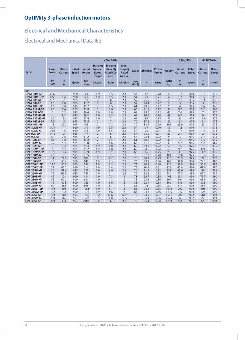
OptIMity 3-phase induction motors
Electrical and Mechanical Characteristics
Leroy-Somer - OptIMity 3-phase induction motors - 5472 en – 2017.03 / b
Electrical and Mechanical Data IE2
6POPTA 80M-6P 0.37 1.1 920 3.9 1.9 5.5 2.1 54 67 0.70 10 1.2 910 1.1 915OPTA 80M1-6P 0.55 1.6 920 5.8 1.9 5.5 2.1 54 70 0.71 12 1.7 910 1.5 915OPTA 90S-6P 0.75 2 935 7.7 2 6 2.1 57 75.9 0.71 15 2.1 935 1.9 935OPTA 90L-6P 1.1 2.8 935 11.2 2 6 2.1 57 78.1 0.72 19 3 935 3 935OPTA 100L-6P 1.5 3.8 945 15.2 2 6.5 2.1 61 79.8 0.72 23 4 945 3.6 945OPTA 112M-6P 2.2 5.4 965 21.8 2 6.6 2.1 65 81.8 0.72 30 5.7 965 5.2 965OPTA 132S-6P 3 7.2 975 29.4 1.9 6.8 2.1 69 83.3 0.72 40 7.6 975 7 975OPTA 132M1-6P 4 9.2 975 39.2 1.9 6.8 2.1 69 84.6 0.74 48 9.7 975 9 975OPTA 132M2-6P 5.5 12.4 975 53.9 1.9 7 2.1 69 86 0.75 55 13 975 11.9 975OPTA 160M-6P 7.5 16 975 73.5 2 7 2.1 70 87.2 0.78 86 16.8 975 15.4 975OPTA 160L-6P 11 22.7 975 108 2 7.2 2.1 70 88.7 0.79 106 23.9 975 22 975OPT 80M1-6P 0.37 1.1 920 3.9 1.9 5.5 2.1 54 67 0.70 15 1.2 910 1.1 915OPT 80M2-6P 0.55 1.6 920 5.8 1.9 5.5 2.1 54 70 0.71 16 1.7 910 1.5 915OPT 90S-6P 0.75 2 935 7.7 2 6 2.1 57 75.9 0.71 20 2.1 935 2 935OPT 90L-6P 1.1 2.8 935 11.2 2 6 2.1 57 78.1 0.72 24 3 935 2.7 935OPT 100L-6P 1.5 3.8 945 15.2 2 6.5 2.1 61 79.8 0.72 30 4 945 3.6 945OPT 112M-6P 2.2 5.4 965 21.8 2 6.6 2.1 65 81.8 0.72 39 5.7 965 5.2 965OPT 132S-6P 3 7.2 975 29.4 1.9 6.8 2.1 69 83.3 0.72 55 7.6 975 7 975OPT 132M1-6P 4 9.2 975 39.2 1.9 6.8 2.1 69 84.6 0.74 68 9.7 975 8.9 975OPT 132M2-6P 5.5 12.4 975 53.9 1.9 7 2.1 69 86 0.75 73 13 975 11.9 975OPT 160M-6P 7.5 16 975 73.5 2 7 2.1 70 87.2 0.78 104 16.8 975 15.4 975OPT 160L-6P 11 22.7 975 108 2 7.2 2.1 70 88.7 0.79 126 23.9 975 22 975OPT 180L-6P 15 30.2 980 146 1.9 7.3 2.1 73 89.7 0.80 163 31.8 980 29.1 980OPT 200L1-6P 18.5 36.9 985 180 1.9 7.3 2.1 73 90.4 0.80 215 38.9 980 35.6 985OPT 200L2-6P 22 43.1 980 214 1.9 7.4 2.1 73 90.9 0.81 238 45.4 980 41.6 980OPT 225M-6P 30 57.6 985 291 1.9 6.9 2.1 74 91.7 0.82 288 60.6 985 56 985OPT 250M-6P 37 69.8 985 359 1.9 7.1 2.1 76 92.2 0.83 354 73.5 985 67.3 985OPT 280S-6P 45 82.4 990 434 1.9 7.3 2 78 92.7 0.85 463 86.8 990 79.5 990OPT 280M-6P 55 99.2 990 531 1.9 7.3 2 78 93.1 0.86 507 104 990 95.6 990OPT 315S-6P 75 138 990 723 1.9 6.6 2 83 93.7 0.84 860 145 990 133 990OPT 315M-6P 90 163 990 868 1.9 6.7 2 83 94 0.85 980 171 990 157 990OPT 315L1-6P 110 198 990 1061 1.9 6.7 2 83 94.3 0.85 1010 209 990 191 990OPT 315L2-6P 132 234 990 1273 1.9 6.8 2 83 94.6 0.86 1135 247 990 226 990OPT 355S-6P 160 283 993 1540 1.54 6.32 2.67 78 94.9 0.87 1511 292 992 281 993OPT 355M-6P 200 360 994 1924 1.78 6.8 2.95 78 95.1 0.86 1628 369 992 355 994OPT 355L-6P 250 434 993 2404 1.48 6 2.5 78 95.1 0.88 1700 454 991 428 993
Type
400V 50Hz 380V/50Hz 415V/50Hz
Rated Power
Rated Current
Rated Speed
Rated Torque
Starting Torque/
Rated Torque
Starting Current/
Rated Cur-rent
Max. Torque/
Rated Torque
Noise EfficiencyPower Factor
WeightRated
CurrentRated Speed
Rated Current
Rated Speed
PnkW
InA
r/minMn
N.mMd/Mn Id/In Mm/Mn
LWAdb(A)
% cosφ IM B3kg
InA
r/minInA
r/min
19
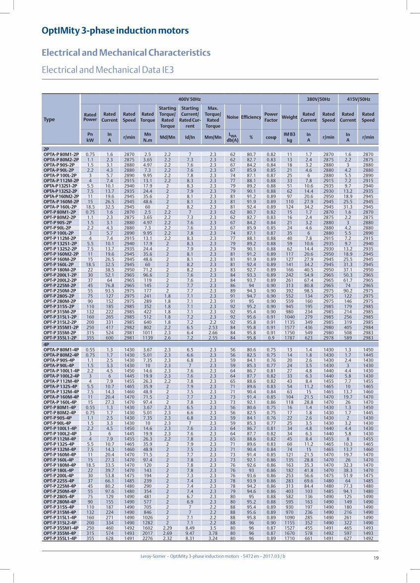
OptIMity 3-phase induction motors
Electrical and Mechanical Characteristics
Leroy-Somer - OptIMity 3-phase induction motors - 5472 en – 2017.03 / b
Electrical and Mechanical Data IE3
2POPTA-P 80M1-2P 0.75 1.6 2870 2.5 2.2 7 2.3 62 80.7 0.82 11 1.7 2870 1.6 2870OPTA-P 80M2-2P 1.1 2.3 2875 3.65 2.2 7.3 2.3 62 82.7 0.83 13 2.4 2875 2.2 2875OPTA-P 90S-2P 1.5 3.1 2880 4.97 2.2 7.6 2.3 67 84.2 0.84 18 3.2 2880 3 2880OPTA-P 90L-2P 2.2 4.3 2880 7.3 2.2 7.6 2.3 67 85.9 0.85 21 4.6 2880 4.2 2880OPTA-P 100L-2P 3 5.7 2890 9.95 2.2 7.8 2.3 74 87.1 0.87 25 6 2880 5.5 2890OPTA-P 112M-2P 4 7.4 2915 13.1 2.2 8.3 2.3 77 88.1 0.88 33 7.8 2915 7.2 2915OPTA-P 132S1-2P 5.5 10.1 2940 17.9 2 8.3 2.3 79 89.2 0.88 51 10.6 2935 9.7 2940OPTA-P 132S2-2P 7.5 13.7 2935 24.4 2 7.9 2.3 79 90.1 0.88 62 14.4 2930 13.2 2935OPTA-P 160M2-2P 11 19.6 2945 35.6 2 8.1 2.3 81 91.2 0.89 97 20.6 2950 18.9 2945OPTA-P 160M-2P 15 26.5 2945 48.6 2 8.1 2.3 81 91.9 0.89 110 27.9 2945 25.5 2945OPTA-P 160L-2P 18.5 32.5 2945 60 2 8.2 2.3 81 92.4 0.89 124 34.2 2945 31.3 2945OPT-P 80M1-2P 0.75 1.6 2870 2.5 2.2 7 2.3 62 80.7 0.82 15 1.7 2870 1.6 2870OPT-P 80M2-2P 1.1 2.3 2875 3.65 2.2 7.3 2.3 62 82.7 0.83 16 2.4 2875 2.2 2875OPT-P 90S-2P 1.5 3.1 2880 4.97 2.2 7.6 2.3 67 84.2 0.84 21 3.2 2880 3 2880OPT-P 90L-2P 2.2 4.3 2880 7.3 2.2 7.6 2.3 67 85.9 0.85 24 4.6 2880 4.2 2880OPT-P 100L-2P 3 5.7 2890 9.95 2.2 7.8 2.3 74 87.1 0.87 35 6 2880 5.5 2890OPT-P 112M-2P 4 7.4 2915 13.1 2.2 8.3 2.3 77 88.1 0.88 40 7.8 2915 7.2 2915OPT-P 132S1-2P 5.5 10.1 2940 17.9 2 8.3 2.3 79 89.2 0.88 59 10.6 2935 9.7 2940OPT-P 132S2-2P 7.5 13.7 2935 24.4 2 7.9 2.3 79 90.1 0.88 62 14.4 2930 13.2 2935OPT-P 160M2-2P 11 19.6 2945 35.6 2 8.1 2.3 81 91.2 0.89 117 20.6 2950 18.9 2945OPT-P 160M-2P 15 26.5 2945 48.6 2 8.1 2.3 81 91.9 0.89 127 27.9 2945 25.5 2945OPT-P 160L-2P 18.5 32.5 2945 60 2 8.2 2.3 81 92.4 0.89 141 34.2 2945 31.3 2945OPT-P 180M-2P 22 38.5 2950 71.2 2 8.2 2.3 83 92.7 0.89 166 40.5 2950 37.1 2950OPT-P 200L1-2P 30 52.1 2965 96.6 2 7.6 2.3 84 93.3 0.89 242 54.9 2965 50.3 2965OPT-P 200L2-2P 37 64 2965 119 2 7.6 2.3 84 93.7 0.89 261 67.4 2965 61.7 2965OPT-P 225M-2P 45 76.8 2965 145 2 7.7 2.3 86 94 0.90 313 80.8 2965 74 2965OPT-P 250M-2P 55 93.5 2975 177 2 7.7 2.3 89 94.3 0.90 392 98.5 2975 90.2 2975OPT-P 280S-2P 75 127 2975 241 1.8 7.1 2.3 91 94.7 0.90 552 134 2975 122 2975OPT-P 280M-2P 90 152 2975 289 1.8 7.1 2.3 91 95 0.90 559 160 2975 146 2975OPT-P 315S-2P 110 185 2985 352 1.8 7.1 2.3 92 95.2 0.90 945 195 2985 179 2985OPT-P 315M-2P 132 222 2985 422 1.8 7.1 2.3 92 95.4 0.90 980 234 2985 214 2985OPT-P 315L1-2P 160 265 2985 512 1.8 7.2 2.3 92 95.6 0.91 1040 279 2985 256 2985OPT-P 315L2-2P 200 331 2985 640 1.8 7.2 2.2 92 95.8 0.91 1135 349 2985 319 2985OPT-P 355M1-2P 250 417 2982 802 2.2 6.5 2.53 84 95.8 0.91 1577 436 2980 405 2984OPT-P 355M-2P 315 524 2981 1011 2.3 6.4 2.66 84 95.8 0.91 1750 549 2980 508 2983OPT-P 355L1-2P 355 600 2981 1139 2.6 7.2 2.55 84 95.8 0.9 1787 623 2978 589 2983
Type
400V 50Hz 380V/50Hz 415V/50Hz
Rated Power
Rated Current
Rated Speed
Rated Torque
Starting Torque/
Rated Torque
Starting Current/
Rated Cur-rent
Max. Torque/
Rated Torque
Noise EfficiencyPower Factor
WeightRated
CurrentRated Speed
Rated Current
Rated Speed
PnkW
InA
r/minMn
N.mMd/Mn Id/In Mm/Mn
LWAdb(A)
% cosφ IM B3kg
InA
r/minInA
r/min
4POPTA-P 80M1-4P 0.55 1.3 1430 3.67 2.3 6.5 2.3 56 80.6 0.75 13 1.4 1430 1.3 1450OPTA-P 80M2-4P 0.75 1.7 1430 5.01 2.3 6.6 2.3 56 82.5 0.75 14 1.8 1430 1.7 1445OPTA-P 90S-4P 1.1 2.5 1430 7.35 2.3 6.8 2.3 59 84.1 0.76 20 2.6 1430 2.4 1430OPTA-P 90L-4P 1.5 3.3 1430 10 2.3 7 2.3 59 85.3 0.77 24 3.5 1430 3 1430OPTA-P 100L1-4P 2.2 4.5 1450 14.6 2.3 7.6 2.3 64 86.7 0.81 27 4.8 1440 4.4 1430OPTA-P 100L2-4P 3 6 1445 19.9 2.3 7.6 2.3 64 87.7 0.82 33 6.3 1440 5.8 1430OPTA-P 112M-4P 4 7.9 1455 26.3 2.2 7.8 2.3 65 88.6 0.82 43 8.4 1455 7.7 1455OPTA-P 132S-4P 5.5 10.7 1465 35.9 2 7.9 2.3 71 89.6 0.83 54 11.2 1465 10 1465OPTA-P 132M-4P 7.5 14.3 1460 48.9 2 7.5 2.3 71 90.4 0.84 63 15 1465 13.7 1460OPTA-P 160M-4P 11 20.4 1470 71.5 2 7.7 2.3 73 91.4 0.85 104 21.5 1470 19.7 1470OPTA-P 160L-4P 15 27.3 1470 97.4 2 7.8 2.3 73 92.1 0.86 118 28.8 1470 26 1470OPT-P 80M1-4P 0.55 1.3 1430 3.67 2.3 6.5 2.3 56 80.6 0.75 16 1.4 1430 1.3 1450OPT-P 80M2-4P 0.75 1.7 1430 5.01 2.3 6.6 2.3 56 82.5 0.75 17 1.8 1430 1.7 1445OPT-P 90S-4P 1.1 2.5 1430 7.35 2.3 6.8 2.3 59 84.1 0.76 22 2.6 1430 2 1430OPT-P 90L-4P 1.5 3.3 1430 10 2.3 7 2.3 59 85.3 0.77 25 3.5 1430 3.2 1430OPT-P 100L1-4P 2.2 4.5 1450 14.6 2.3 7.6 2.3 64 86.7 0.81 34 4.8 1440 4.4 1430OPT-P 100L2-4P 3 6 1445 19.9 2.3 7.6 2.3 64 87.7 0.82 34 6.3 1440 5.8 1430OPT-P 112M-4P 4 7.9 1455 26.3 2.2 7.8 2.3 65 88.6 0.82 45 8.4 1455 8 1455OPT-P 132S-4P 5.5 10.7 1465 35.9 2 7.9 2.3 71 89.6 0.83 60 11.2 1465 10.3 1465OPT-P 132M-4P 7.5 14.3 1460 48.9 2 7.5 2.3 71 90.4 0.84 74 15 1465 13.7 1460OPT-P 160M-4P 11 20.4 1470 71.5 2 7.7 2.3 73 91.4 0.85 121 21.5 1470 19.7 1470OPT-P 160L-4P 15 27.3 1470 97.4 2 7.8 2.3 73 92.1 0.86 135 28.8 1470 26 1470OPT-P 180M-4P 18.5 33.5 1470 120 2 7.8 2.3 76 92.6 0.86 163 35.3 1470 32.3 1470OPT-P 180L-4P 22 39.7 1470 143 2 7.8 2.3 76 93 0.86 182 41.8 1470 38.3 1470OPT-P 200L-4P 30 53.8 1475 194 2 7.3 2.3 76 93.6 0.86 253 56.6 1475 51.9 1475OPT-P 225S-4P 37 66.1 1485 239 2 7.4 2.3 78 93.9 0.86 283 69.6 1480 64 1485OPT-P 225M-4P 45 80.2 1480 290 2 7.4 2.3 78 94.2 0.86 313 84.4 1480 77.3 1480OPT-P 250M-4P 55 97.6 1480 354 2 7.4 2.3 79 94.6 0.86 403 103 1485 94.1 1480OPT-P 280S-4P 75 129 1490 481 2 6.7 2.3 80 95 0.88 582 136 1490 125 1490OPT-P 280M-4P 90 155 1490 577 2 6.9 2.3 80 95.2 0.88 595 163 1490 149 1490OPT-P 315S-4P 110 187 1490 705 2 7 2.2 88 95.4 0.89 930 197 1490 180 1490OPT-P 315M-4P 132 224 1490 846 2 7 2.2 88 95.6 0.89 970 236 1490 216 1490OPT-P 315L1-4P 160 271 1490 1026 2 7.1 2.2 88 95.8 0.89 1090 285 1490 261 1490OPT-P 315L2-4P 200 334 1490 1282 2 7.1 2.2 88 96 0.90 1155 352 1490 322 1490OPT-P 355M1-4P 250 460 1492 1602 2.29 8.49 3.5 80 96 0.87 1527 455 1491 465 1493OPT-P 355M-4P 315 574 1493 2017 2.69 9.47 3.78 80 96 0.87 1670 578 1492 597 1493OPT-P 355L1-4P 355 628 1491 2276 2.32 8.31 3.24 80 96 0.89 1710 661 1491 627 1492

20
OptIMity 3-phase induction motors
Electrical and Mechanical Characteristics
Leroy-Somer - OptIMity 3-phase induction motors - 5472 en – 2017.03 / b
Electrical and Mechanical Data IE3
6POPTA-P 80M1-6P 0.37 1.1 920 3.88 1.9 5.5 2 54 68 0.70 10 1.2 910 1.1 915OPTA-P 80M2-6P 0.55 1.5 925 5.68 1.9 5.8 2.1 54 72 0.71 13 1.6 925 1.5 925OPTA-P 90S-6P 0.75 1.9 945 7.58 2 6 2.1 57 78.9 0.71 16 2 945 1.9 955OPTA-P 90L-6P 1.1 2.7 950 11.1 2 6 2.1 57 81 0.73 22 2.8 950 3 945OPTA-P 100L-6P 1.5 3.6 955 15.1 2 6.5 2.1 61 82.5 0.73 25 3.8 950 3.5 950OPTA-P 112M-6P 2.2 5.1 965 21.8 2 6.6 2.1 65 84.3 0.74 34 5.4 965 4.9 965OPTA-P 132S-6P 3 6.8 980 29.4 1.9 6.8 2.1 69 85.6 0.74 45 7.2 975 6.6 980OPTA-P 132M1-6P 4 9 980 39.2 1.9 6.8 2.1 69 86.8 0.74 54 9.5 975 9 980OPTA-P 132M2-6P 5.5 12 980 53.9 1.9 7 2.1 69 88 0.75 61 12.7 975 11.6 980OPTA-P 160M-6P 7.5 15.4 980 73.1 1.9 7 2.1 70 89.1 0.79 95 16.2 980 14.8 980OPTA-P 160L-6P 11 22 980 107 1.9 7.2 2.1 70 90.3 0.80 115 23.1 980 21 980OPT-P 80M1-6P 0.37 1.1 920 3.88 1.9 5.5 2 54 68 0.70 15 1.2 910 1.1 915OPT-P 80M2-6P 0.55 1.5 925 5.68 1.9 5.8 2.1 54 72 0.71 16 1.6 925 1.5 925OPT-P 90S-6P 0.75 1.9 945 7.58 2 6 2.1 57 78.9 0.71 20 2 945 2 955OPT-P 90L-6P 1.1 2.7 950 11.1 2 6 2.1 57 81 0.73 24 2.8 950 2.6 945OPT-P 100L-6P 1.5 3.6 955 15.1 2 6.5 2.1 61 82.5 0.73 33 3.8 950 3.5 950OPT-P 112M-6P 2.2 5.1 965 21.8 2 6.6 2.1 65 84.3 0.74 40 5.4 965 4.9 965OPT-P 132S-6P 3 6.8 980 29.4 1.9 6.8 2.1 69 85.6 0.74 56 7.2 975 7 980OPT-P 132M1-6P 4 9 980 39.2 1.9 6.8 2.1 69 86.8 0.74 63 9.5 975 8.7 980OPT-P 132M2-6P 5.5 12 980 53.9 1.9 7 2.1 69 88 0.75 71 12.7 975 11.6 980OPT-P 160M-6P 7.5 15.4 980 73.1 1.9 7 2.1 70 89.1 0.79 112 16.2 980 14.8 980OPT-P 160L-6P 11 22 980 107 1.9 7.2 2.1 70 90.3 0.80 132 23.1 980 21 980OPT-P 180L-6P 15 29.3 980 146 1.9 7.3 2.1 73 91.2 0.81 172 30.9 980 28.2 980OPT-P 200L1-6P 18.5 36 985 179 1.9 7.3 2.1 73 91.7 0.81 215 37.8 985 34.7 985OPT-P 200L2-6P 22 42.5 985 213 1.9 7.4 2.1 73 92.2 0.81 221 44.8 985 41 985OPT-P 225M-6P 30 56.2 985 291 1.9 6.9 2.1 74 92.9 0.83 292 59.1 985 54 985OPT-P 250M-6P 37 68.1 985 359 1.9 7.1 2.1 76 93.3 0.84 375 71.7 985 65.7 985OPT-P 280S-6P 45 81.6 990 434 1.9 7.3 2 78 93.7 0.85 497 85.8 990 78.6 990OPT-P 280M-6P 55 98.1 990 531 1.9 7.3 2 78 94.1 0.86 537 103 990 94.6 990OPT-P 315S-6P 75 136 990 723 1.9 6.6 2 83 94.6 0.84 830 143 990 131 990OPT-P 315M-6P 90 161 990 868 1.9 6.7 2 83 94.9 0.85 910 170 990 155 990OPT-P 315L1-6P 110 196 990 1061 1.9 6.7 2 83 95.1 0.85 1035 207 990 189 990OPT-P 315L2-6P 132 232 990 1273 1.9 6.8 2 83 95.4 0.86 1120 244 990 224 990OPT-P 355S-6P 160 290 995 1538 1.7 6.8 2.9 78 95.6 0.86 1628 296 994 290 995OPT-P 355M1-6P 200 355 994 1923 1.7 6.7 3 78 95.8 0.87 1800 365 994 352 995OPT-P 355L-6P 250 467 994 2404 1.7 6.63 2.82 78 95.8 0.86 1878 464 994 472 995
Type
400V 50Hz 380V/50Hz 415V/50Hz
Rated Power
Rated Current
Rated Speed
Rated Torque
Starting Torque/
Rated Torque
Starting Current/
Rated Cur-rent
Max. Torque/
Rated Torque
Noise EfficiencyPower Factor
WeightRated
CurrentRated Speed
Rated Current
Rated Speed
PnkW
InA
r/minMn
N.mMd/Mn Id/In Mm/Mn
LWAdb(A)
% cosφ IM B3kg
InA
r/minInA
r/min
21
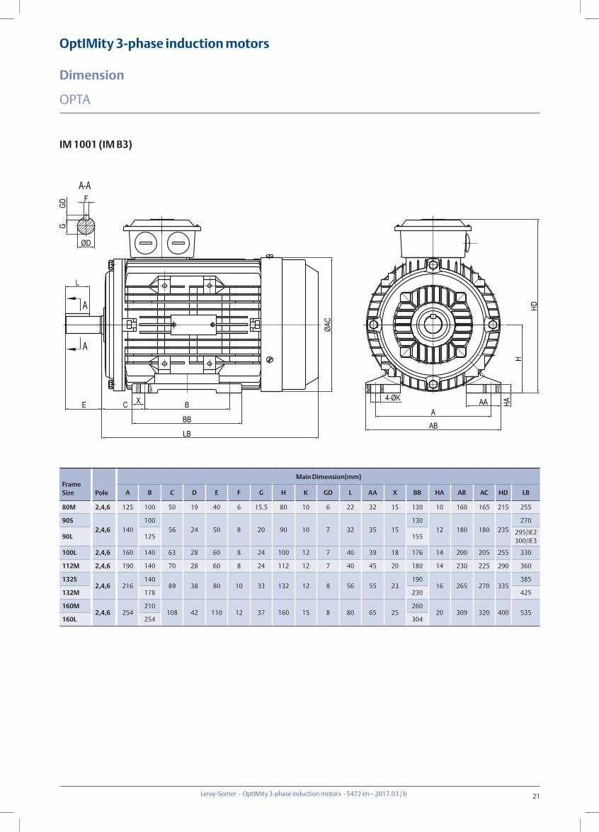
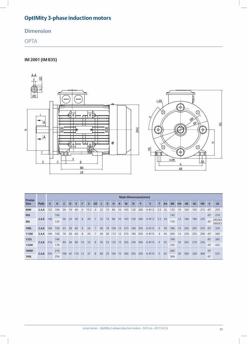
OptIMity 3-phase induction motors
Dimension
Leroy-Somer - OptIMity 3-phase induction motors - 5472 en – 2017.03 / b
OPTA
IM 1001 (IM B3)
Frame Size Pole
Main Dimension(mm)
A B C D E F G H K GD L AA X BB HA AB AC HD LB
80M 2,4,6 125 100 50 19 40 6 15.5 80 10 6 22 32 15 130 10 160 165 215 255
90S2,4,6 140
10056 24 50 8 20 90 10 7 32 35 15
13012 180 180 235
270
90L 125 155295/IE2300/IE3
100L 2,4,6 160 140 63 28 60 8 24 100 12 7 40 39 18 176 14 200 205 255 330
112M 2,4,6 190 140 70 28 60 8 24 112 12 7 40 45 20 180 14 230 225 290 360
132S2,4,6 216
14089 38 80 10 33 132 12 8 56 55 23
19016 265 270 335
385
132M 178 230 425
160M2,4,6 254
210108 42 110 12 37 160 15 8 80 65 25
26020 309 320 400 535
160L 254 304

22
OptIMity 3-phase induction motors
Dimension
Leroy-Somer - OptIMity 3-phase induction motors - 5472 en – 2017.03 / b
OPTA
IM 3001 (IM B5)
Frame Size Pole
Main Dimension(mm)
D E F G GD L M N P S T AC HF HJ α LB
80M 2,4,6 19 40 6 15.5 6 22 165 130 200 4-Φ12 3.5 165 245 145
45°
255
90S2,4,6 24 50 8 20 7 32 165 130 200 4-Φ12 3.5 180 265 165
270
90L295/IE2300/IE3
100L 2,4,6 28 60 8 24 7 40 215 180 250 4-Φ15 4 205 300 175 330
112M 2,4,6 28 60 8 24 7 40 215 180 250 4-Φ15 4 225 315 190 360
132S2,4,6 38 80 10 33 8 56 265 230 300 4-Φ15 4 270 370 220
385
132M 425
160M2,4,6 42 110 12 37 8 80 300 250 350 4-Φ19 5 320 435 260 535
160L
23
OptIMity 3-phase induction motors
Dimension
Leroy-Somer - OptIMity 3-phase induction motors - 5472 en – 2017.03 / b
OPTA
IM 2001 (IM B35)
Frame Size Pole
Main Dimension(mm)
A B C D E F G GD L X H K M N P S T AA BB HA AB AC HD α LB
80M 2,4,6 125 100 50 19 40 6 15.5 6 22 15 80 10 165 130 200 4-Φ12 3.5 32 135 10 160 165 215 45° 255
90S2,4,6 140
10056 24 50 8 20 7 32 15 90 10 165 130 200 4-Φ12 3.5 34
14512 180 180 235
45° 270
90L 125 170 45°295/IE2300/IE3
100L 2,4,6 160 140 63 28 60 8 24 7 40 18 100 12 215 180 250 4-Φ15 4 39 186 14 200 205 255 45° 330
112M 2,4,6 190 140 70 28 60 8 24 7 40 20 112 12 215 180 250 4-Φ15 4 45 200 14 230 225 290 45° 360
132S2,4,6 216
14089 38 80 10 33 8 56 23 132 12 265 230 300 4-Φ15 4 55
19016 265 270 335
45° 385
132M 178 230 45° 425
160M2,4,6 254
210108 42 110 12 37 8 80 25 160 15 300 250 350 4-Φ19 5 65
26020 309 320 400
45°535
160L 254 304 45°
24
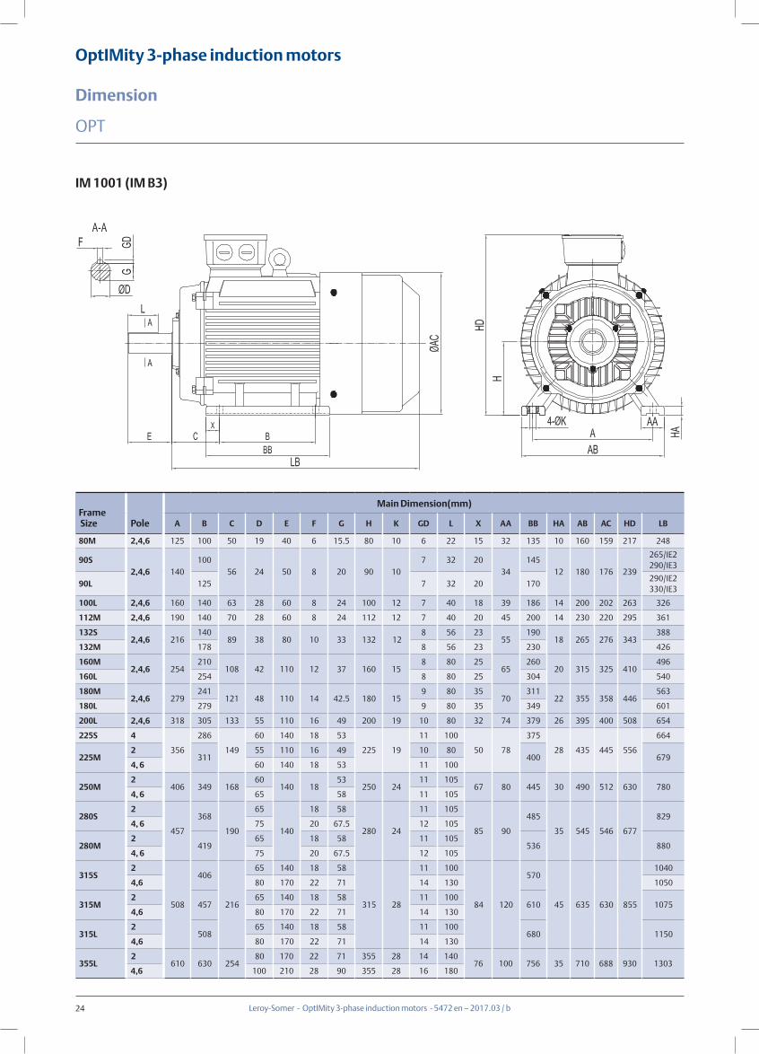
OptIMity 3-phase induction motors
Dimension
Leroy-Somer - OptIMity 3-phase induction motors - 5472 en – 2017.03 / b
OPT
IM 1001 (IM B3)
Frame Size Pole
Main Dimension(mm)
A B C D E F G H K GD L X AA BB HA AB AC HD LB
80M 2,4,6 125 100 50 19 40 6 15.5 80 10 6 22 15 32 135 10 160 159 217 248
90S2,4,6 140
10056 24 50 8 20 90 10
7 32 2034
14512 180 176 239
265/IE2290/IE3
90L 125 7 32 20 170290/IE2330/IE3
100L 2,4,6 160 140 63 28 60 8 24 100 12 7 40 18 39 186 14 200 202 263 326
112M 2,4,6 190 140 70 28 60 8 24 112 12 7 40 20 45 200 14 230 220 295 361
132S2,4,6 216
14089 38 80 10 33 132 12
8 56 2355
19018 265 276 343
388
132M 178 8 56 23 230 426
160M2,4,6 254
210108 42 110 12 37 160 15
8 80 2565
26020 315 325 410
496
160L 254 8 80 25 304 540
180M2,4,6 279
241121 48 110 14 42.5 180 15
9 80 3570
31122 355 358 446
563
180L 279 9 80 35 349 601
200L 2,4,6 318 305 133 55 110 16 49 200 19 10 80 32 74 379 26 395 400 508 654
225S 4
356
286
149
60 140 18 53
225 19
11 100
50 78
375
28 435 445 556
664
225M2
31155 110 16 49 10 80
400 6794, 6 60 140 18 53 11 100
250M2
406 349 16860
140 1853
250 2411 105
67 80 445 30 490 512 630 7804, 6 65 58 11 105
280S2
457
368
190
65
140
18 58
280 24
11 105
85 90
485
35 545 546 677
8294, 6 75 20 67.5 12 105
280M2
41965 18 58 11 105
536 8804, 6 75 20 67.5 12 105
315S2
508
406
216
65 140 18 58
315 28
11 100
84 120
570
45 635 630 855
1040
4,6 80 170 22 71 14 130 1050
315M2
45765 140 18 58 11 100
610 10754,6 80 170 22 71 14 130
315L2
50865 140 18 58 11 100
680 11504,6 80 170 22 71 14 130
355L2
610 630 25480 170 22 71 355 28 14 140
76 100 756 35 710 688 930 13034,6 100 210 28 90 355 28 16 180

25
OptIMity 3-phase induction motors
Dimension
Leroy-Somer - OptIMity 3-phase induction motors - 5472 en – 2017.03 / b
OPT
IM 3001 (IM B5)
Frame Size Pole
Main Dimension(mm)
D E F G GD L M N P S T AC HF HJ α LB
80M 2,4,6 19 40 6 15.5 6 22 165 130 200 4-Φ12 3.5 159 237 137
45°
248
90S2,4,6 24 50 8 20 7 32 165 130 200 4-Φ12 3.5 176 249 249
265/IE2290/IE3
90L290/IE2330/IE3
100L 2,4,6 28 60 8 24 7 40 215 180 250 4-Φ15 4 202 288 163 326
112M 2,4,6 28 60 8 24 7 40 215 180 250 4-Φ15 4 220 308 183 361
132S2,4,6 38 80 10 33 8 56 265 230 300 4-Φ15 4 276 361 211
388
132M 426
160M2,4,6 42 110 12 37 8 80 300 250 350 4-Φ19 5 325 425 250
496
160L 540
180M2,4,6 48 110 14 42.5 9 80 300 250 350 4-Φ19 5 358 441 266
563
180L 601
200L 2,4,6 55 110 16 49 10 80 350 300 400 4-Φ19 5 400 508 308 654
225S 4 60 140 18 53 11 100
400 350 450 8-Φ19 5 445 556 331
22.5°
664
225M2 55 110 16 49 10 80
6794,6 60 140 18 53 11 100
250M2 60
140 1853
11 105 500 450 550 8-Φ19 5 512 655 380 7804,6 65 58
280S2 65
140
18 58 11
105 500 450 550 8-Φ19 5 546 672 397
8294,6 75 20 67.5 12
280M2 65 18 58 11
8804,6 75 20 67.5 12
26
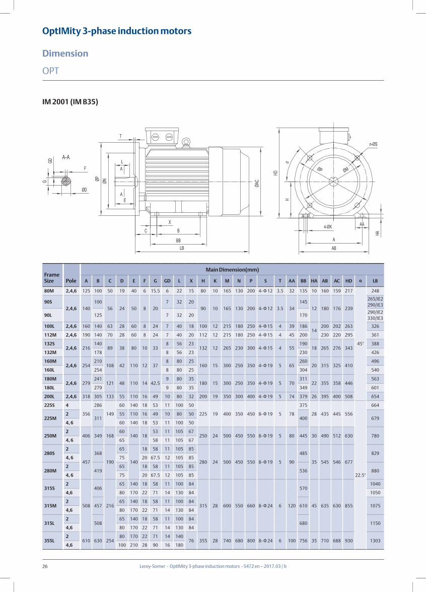
OptIMity 3-phase induction motors
Dimension
Leroy-Somer - OptIMity 3-phase induction motors - 5472 en – 2017.03 / b
OPT
IM 2001 (IM B35)
Frame Size Pole
Main Dimension(mm)
A B C D E F G GD L X H K M N P S T AA BB HA AB AC HD α LB
80M 2,4,6 125 100 50 19 40 6 15.5 6 22 15 80 10 165 130 200 4-Φ12 3.5 32 135 10 160 159 217
45°
248
90S2,4,6 140
10056 24 50 8 20
7 32 2090 10 165 130 200 4-Φ12 3.5 34
14512 180 176 239
265/IE2290/IE3
90L 125 7 32 20 170290/IE2330/IE3
100L 2,4,6 160 140 63 28 60 8 24 7 40 18 100 12 215 180 250 4-Φ15 4 39 18614
200 202 263 326
112M 2,4,6 190 140 70 28 60 8 24 7 40 20 112 12 215 180 250 4-Φ15 4 45 200 230 220 295 361
132S2,4,6 216
14089 38 80 10 33
8 56 23132 12 265 230 300 4-Φ15 4 55
19018 265 276 343
388
132M 178 8 56 23 230 426
160M2,4,6 254
210108 42 110 12 37
8 80 25160 15 300 250 350 4-Φ19 5 65
26020 315 325 410
496
160L 254 8 80 25 304 540
180M2,4,6 279
241121 48 110 14 42.5
9 80 35180 15 300 250 350 4-Φ19 5 70
31122 355 358 446
563
180L 279 9 80 35 349 601
200L 2,4,6 318 305 133 55 110 16 49 10 80 32 200 19 350 300 400 4-Φ19 5 74 379 26 395 400 508 654
225S 4
356
286
149
60 140 18 53 11 100 50
225 19 400 350 450 8-Φ19 5 78
375
28 435 445 556
22.5°
664
225M2
31155 110 16 49 10 80 50
400 6794, 6 60 140 18 53 11 100 50
250M2
406 349 16860
140 1853 11 105 67
250 24 500 450 550 8-Φ19 5 80 445 30 490 512 630 7804, 6 65 58 11 105 67
280S2
457
368
190
65
140
18 58 11 105 85
280 24 500 450 550 8-Φ19 5 90
485
35 545 546 677
8294, 6 75 20 67.5 12 105 85
280M2
41965 18 58 11 105 85
536 8804, 6 75 20 67.5 12 105 85
315S2
508
406
216
65 140 18 58 11 100 84
315 28 600 550 660 8-Φ24 6 120
570
45 635 630 855
1040
4,6 80 170 22 71 14 130 84 1050
315M2
45765 140 18 58 11 100 84
610 10754,6 80 170 22 71 14 130 84
315L2
50865 140 18 58 11 100 84
680 11504,6 80 170 22 71 14 130 84
355L2
610 630 25480 170 22 71 14 140
76 355 28 740 680 800 8-Φ24 6 100 756 35 710 688 930 13034,6 100 210 28 90 16 180
27
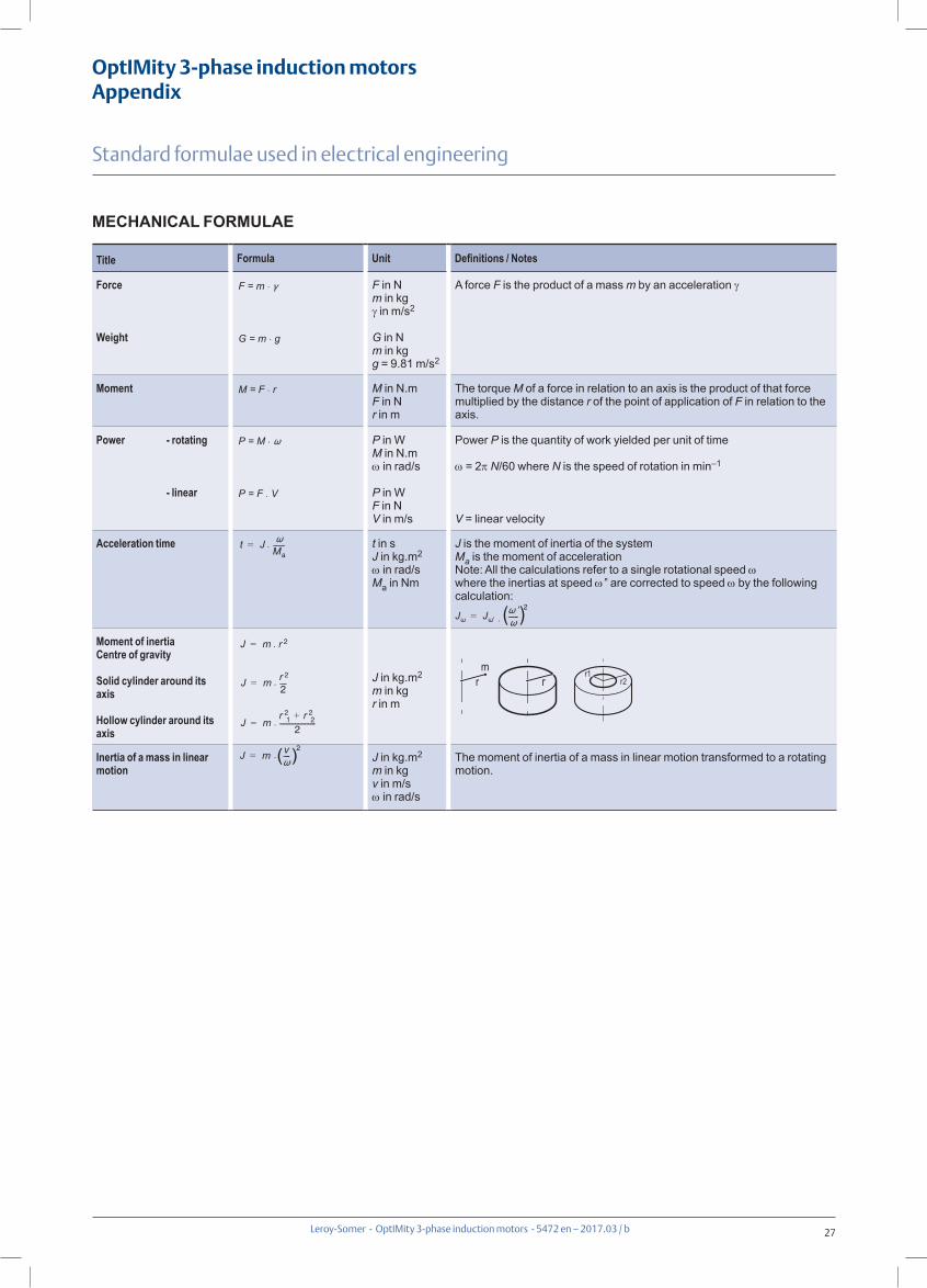
OptIMity 3-phase induction motorsAppendix
Leroy-Somer - OptIMity 3-phase induction motors - 5472 en – 2017.03 / b
Standard formulae used in electrical engineering
MECHANICAL FORMULAE
Title Formula Unit Definitions / Notes
Force
Weight
F in Nm in kgγ in m/s2
G in Nm in kgg = 9.81 m/s2
A force F is the product of a mass m by an acceleration γ
Moment M in N.mF in Nr in m
The torque M of a force in relation to an axis is the product of that force multiplied by the distance r of the point of application of F in relation to the axis.
Power - rotating
- linear
P in WM in N.mω in rad/s
P in WF in NV in m/s
Power P is the quantity of work yielded per unit of time
ω = 2π N/60 where N is the speed of rotation in min–1
V = linear velocity
Acceleration time t in sJ in kg.m2
ω in rad/sMa in Nm
J is the moment of inertia of the systemMa is the moment of accelerationNote: All the calculations refer to a single rotational speed ωwhere the inertias at speed ω’’ are corrected to speed ω by the following calculation:
Moment of inertiaCentre of gravity
Solid cylinder around its axis
Hollow cylinder around its axis
J in kg.m2
m in kgr in m
r1r2rr
m
r1r2rr
m
Inertia of a mass in linear motion
J in kg.m2
m in kgv in m/sω in rad/s
The moment of inertia of a mass in linear motion transformed to a rotating motion.
F = m .
G = m . g
M = F . r
P = M .
P = F .
.
.
V
t JMa-------=
J m r 2=
J m r 2
2----=
J mr 2
1 r 22+
2---------------------=
J m v----2
=
.
.
.( )
J J ------2
= . ( )

28
OptIMity 3-phase induction motorsAppendix
Leroy-Somer - OptIMity 3-phase induction motors - 5472 en – 2017.03 / b
Standard formulae used in electrical engineering
ELECTRICAL FORMULAE
Title Formula Unit Definitions / Notes
Accelerating torqueGeneral formula:
Nm Moment of acceleration Ma is the difference between the motor torque Mmot (estimated), and the resistive torque Mr.(MD, MA, MM, MN, see curve below)N = instantaneous speedNN = rated speed
Power required by the machine
P in WM in N.mω in rad/sηA no units
ηA expresses the efficiency of the driven machine.M is the torque required by the driven machine.
Power drawn by the 3-phase motor
P in WU in VI in A
ϕ phase angle by which the current lags or leads the voltage.U armature voltage.I line current.
Reactive power drawn by the motor
Q in VAR
Reactive power supplied by a bank of capacitors
U in VC in μ Fω in rad/s
U = voltage at the capacitor terminalsC = capacitor capacitanceω = rotational frequency of supply phases (ω = 2πf)
Apparent power S in VA
Power supplied by the 3-phase motor
η expresses motor efficiency at the point of operation under consideration.
Slip Slip is the difference between the actual motor speed N and the synchronous speed NS
Synchronous speed NS in min-1
f in Hzp = number of polesf = frequency of the power supply
Parameters Symbol Unit Torque and current curve as a function of speed
Starting currentRated currentNo-load current
IDINIO
A M
ID
MD
MN
IN
IO
MA
MM
NN NS
N
Current
(Rated)
Torque
(Speed)
(Synchronous)
Starting torque*Run up torqueBreakdown torqueRated torque
MDMA
MM
MN
Nm
Rated speedSynchronous speed
NNNS min-1
* Torque is the usual term for expressing the moment of a force.
MaMD 2MA 2MM MN+ + +
6------------------------------------------------------------ Mr–=
Ma1
NN------- Mmot Mr–( ) Nd
0
NN=
P M ω.ηA
-------------=
P 3 U I ϕcos
ϕcos
= . . .
. . .
. . .
. .
. . . .
Q 3 U I ϕsin=
Q 3 U2 C ω=
S 3 U I=
S P2 Q2+=
P 3 U I=
gNS N–
NS-----------------=
NS120 f.
p----------------=
η
29
OptIMity 3-phase induction motorsAppendix
Leroy-Somer - OptIMity 3-phase induction motors - 5472 en – 2017.03 / b
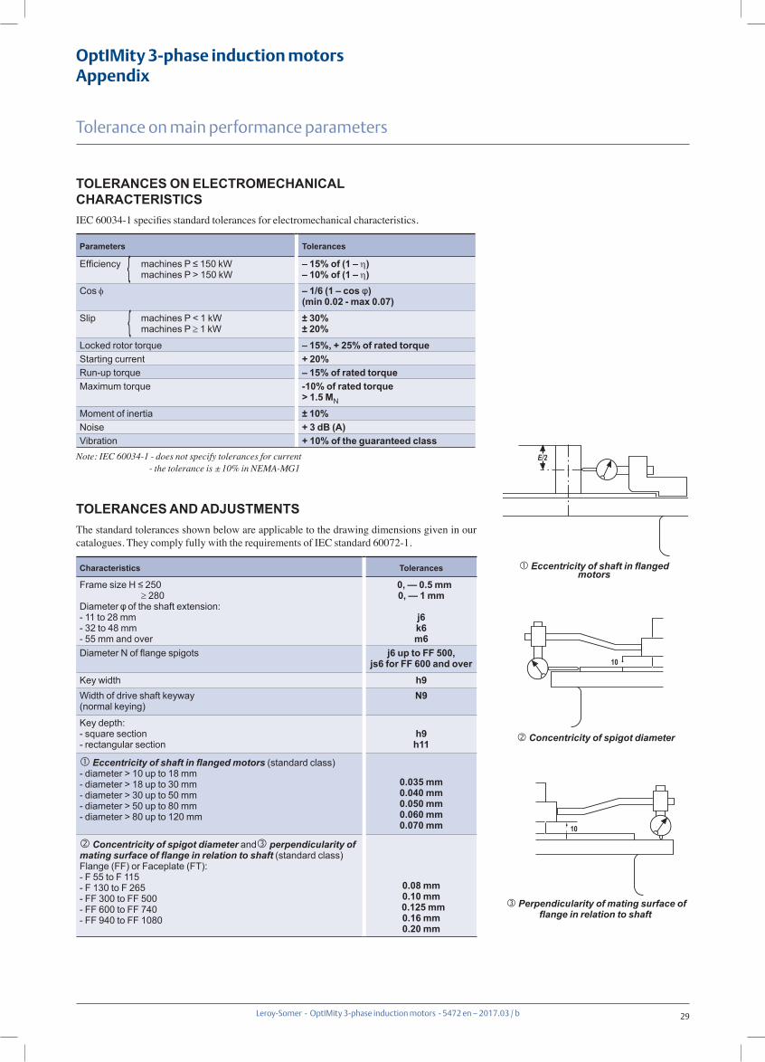
TOLERANCES ON ELECTROMECHANICAL CHARACTERISTICS IEC 60034-1 specifies standard tolerances for electromechanical characteristics.
Parameters Tolerances
Efficiency { machines P ≤ 150 kW machines P > 150 kW
– 15% of (1 – η)– 10% of (1 – η)
Cos φ – 1/6 (1 – cos φ)(min 0.02 - max 0.07)
Slip { machines P < 1 kW machines P ≥ 1 kW
± 30%± 20%
Locked rotor torque – 15%, + 25% of rated torqueStarting current + 20%Run-up torque – 15% of rated torqueMaximum torque -10% of rated torque
> 1.5 MN
Moment of inertia ± 10%Noise + 3 dB (A)Vibration + 10% of the guaranteed class
Note: IEC 60034-1 - does not specify tolerances for current - the tolerance is ± 10% in NEMA-MG1
TOLERANCES AND ADJUSTMENTSThe standard tolerances shown below are applicable to the drawing dimensions given in our catalogues. They comply fully with the requirements of IEC standard 60072-1.
Characteristics Tolerances
Frame size H ≤ 250≥ 280
Diameter φ of the shaft extension:- 11 to 28 mm- 32 to 48 mm- 55 mm and over
0, — 0.5 mm0, — 1 mm
j6k6m6
Diameter N of flange spigots j6 up to FF 500,js6 for FF 600 and over
Key width h9Width of drive shaft keyway (normal keying)
N9
Key depth:- square section- rectangular section
h9h11
� Eccentricity of shaft in flanged motors (standard class)- diameter > 10 up to 18 mm- diameter > 18 up to 30 mm- diameter > 30 up to 50 mm- diameter > 50 up to 80 mm- diameter > 80 up to 120 mm
0.035 mm0.040 mm0.050 mm0.060 mm0.070 mm
� Concentricity of spigot diameter and� perpendicularity of mating surface of flange in relation to shaft (standard class)Flange (FF) or Faceplate (FT):- F 55 to F 115- F 130 to F 265- FF 300 to FF 500- FF 600 to FF 740- FF 940 to FF 1080
0.08 mm0.10 mm
0.125 mm0.16 mm0.20 mm
E/2
10
10
E/2
10
10
� Eccentricity of shaft in flanged motors
� Concentricity of spigot diameter
� Perpendicularity of mating surface of flange in relation to shaft
Tolerance on main performance parameters

www.nidecautomation.com
5472 en – 2017.03 / b
Connect with us at:
twitter.com/ctandls
facebook.com/ctandls
youtube.com/controltechniquesandleroysomer
theautomationengineer.com (blog)
Control Techniques Limited. Registered office: The Gro, Newtown, Powys SY16 3BE. Company registered in England and Wales. Company registration no: 01236886.
Moteurs Leroy-Somer SAS. Registered office: Bd Marcellin Leroy, CS 10015, 16915 Angoulême Cedex 9, France. Registered capital: €65,800,512, RCS Angoulême 338 567 258.