optimization in the abaqus environment using · pdf file2009 abaqus users’ conference 1...
TRANSCRIPT

2009 Abaqus Users’ Conference 1
Optimization in the Abaqus Environment Using TOSCA
Luca Furbatto, Giovanni Di Lorenzo and Claus B.W. Pedersen
Luca Furbatto and Giovanni Di Lorenzo (McLaren Racing), Claus B.W. Pedersen (FE-Design GmbH)
Abstract: The present work shows non-parametric optimization can be applied for practical Abaqus models using different modules of TOSCA.struc. The first study will show how Abaqus/Standard allows topology optimization of large models with TOSCA.struc.topo. Topology optimization is typically used in the early design phase for producing new design suggestions where the optimization targets could be to minimize the mass considering given stiffness demands formulated using displacement constraints. In the second study, Abaqus/Standard and Tosca.struc.shape are applied for shape optimization. The shape modifications are directly performed on the Abaqus CAE model where each node is displaced independently. For the shape optimization the mesh is adapted by an automatic mesh smoothing algorithm. Typically, the optimization-objective in shape optimization is to minimize the maximum stress or maximize the safety-factor for fatigue problems. However, in the present work it will be shown that optimization can directly be executed on the plastic strains for Abaqus/Standard models.
Keywords: Abaqus/Standard, industrial optimization integration, topology optimization, mass minimization, shape optimization and plastic strain minimization.
1. Introduction to topology and shape optimization
The purpose of the present paper is to show that non-parametric optimization allows the optimization to be conducted efficiently in the Abaqus CAE environment. The results of two non-parametric optimization approaches topology and shape are shown. Traditionally, topology optimization is normally applied for determining new conceptual designs for stiffness and shape optimization is applied for stress, strain or fatigue minimization by automatic modifications of the existing surfaces. The present approach ensures that the important know-how regarding Abaqus is reserved in the optimization computations. Additionally, standard pre- and post-processors can be used in the optimization process. Thus, it can be concluded that the non-parametric optimization approach works as add-one module to an already existing CAD and Abaqus CAE workflow. Accordingly, the main advances of using Abaqus/Standard in connection with TOSCA topology and TOSCA shape optimization are:
Use your reliable, validated and tested Abaqus models directly in an optimization.
Including accurate Abaqus contact modeling in the model for the optimization process.
Include geometrical non-linear modeling and material non-linear modeling model in the optimization process.
Consider several load cases in the optimization also temperature loadcases.

2 2009 Abaqus Users’ Conference
Use large industrial 3D models for optimization. Apply different kind of Abaqus elements (continuum, shell, beam, membrane and rigid elements) in the model. Submodeling and substructures are also allowed for the optimization.
2. Topology optimization: Objectives and constraints
Today topology optimization is very well theoretically studied (see [2] and references therein) and also a very common tool in the industrial design process [3-5]. The designs obtained using topology optimization are considered as design proposals. These topology optimized designs can often be rather different compared to designs obtained with a trial and error design process or designs obtained upon improvements of existing design. In topology optimization the density and Young modulus of each element is a design variable. Therefore, one can often have up to millions of design variables but the topology optimization can typically be done in 15-80 optimization iterations [3].
For the topology optimization different response types can be combined for the objective function and/or in the constraints based upon the results of static analysis, modal eigenfrequency analysis and/or frequency responses analysis. Furthermore, one can specify if the objective function should be minimized and maximized or if a Min-Max formulation should be applied. The responses applied in a topology optimization are characterized as following:
Mass of structure:
Structural weight of given area.
Center of gravity of given area (global or local coordinate systems).
Moment of inertia of given area (global or local coordinate systems).
Linear and/or non-linear static analysis:
Compliance of structure for specific loadcases (measure for stiffness of given loadcase).
Displacements for specific loadcases (deflections and rotations in relative, global or local coordinate systems).
Reaction forces for specific loadcases (forces and moments in relative, global or local coordinate systems).
Internal forces for specific loadcases (forces and moments in relative, global or local coordinate systems).
Linear modal eigenfrequency analysis:
Single eigenfrequency.
Sum of eigenfrequencies.
Differences between eigenfrequencies.
Linear frequency response analysis also including acoustic modeling:

2009 Abaqus Users’ Conference 3
Amplitudes, velocities and accelerations (global or local coordinate systems).
Surface velocities of node group.
Pressure in acoustic media - sound pressure level, decibel (dB) or weighted decibels (dBA).
Manufacturing restrictions (the mesh does not have to be regular or symmetric):
Stamping (straight sides of structure in stamping direction).
Casting for avoiding under cuts as shown in figure 1a. The mid plane can be fixed by user or determined automatically during the optimization. The mid plan can also be constraint to contain no holds as shown in figure 1b.
Symmetry constraints (plane, point, rotational and cyclic symmetry and linked symmetry between different subdomains).
Figure 1 - Manufacturing constraints. a) Ensure manufacturing direction including avoiding no undercuts or cavities. b) No material accumulation otherwise problems with cooling can occur. An additional constraint can also ensure that the mid plan has no holds ensuring a
good material flow when molding.
The numerical implementation is done using a mathematical programming algorithm [1] which is useful when having a high number of design variables and relative few objectives and/or constraints. In this context more than a million design variables are not unusual. The sensitivities are based on the theory given in [2] and this theory has been integrated into industrial CAE and CAD systems [3-6].

4 2009 Abaqus Users’ Conference
2.1 Postprocessing using smoothing techniques
When the final topology optimized design is achieved, it consists of a large amount of CAE data (fine meshes where each element has a unique density) and surfaces which are not well defined from a constructor’s point of view. Consequently, an important issue is that the topology optimization data from the optimization should be converted (TOSCA.smooth) into model consisting of well defined surfaces. In this process the design is smoothed to a complete solid/void design. The constructor can export these surface models into CAD or export them directly into a preprocessor
TOSCA.smooth exports the formats STL and IGES for allowing the optimization results to being used in the constructors CAD systems, see figure 2. Splines can also be exported instead of surfaces. Then further modifications can be applied by the constructor and maybe afterwards the structure is reanalyzed in the CAE system.
Figure 2 - Transferring the optimized structure back into the CAD system using smoothed isosurfaces given in STL or IGES format and data reduction.
Postprocessing of the topology optimization results can also be done using the preprocessor in Abaqus CAE. Then the surfaces are exported as a surface element mesh. This surface element mesh consists of shell elements (S3- or S4-elements). The meshing fills the shell model up with continuum finite elements. Then the meshed structure can be analyzed for ensuring that the smoothed model fulfils all original design criteria. This allows the constructor a fast evaluation of the smoothed results.

2009 Abaqus Users’ Conference 5
3. Topology optimization example - Designing a compliant beam for Laboratory Testing
In order to replicate the exact chassis behavior under laboratory conditions a number of compliant beams have been designed to allow more realistic component fatigue testing. In order to be effective the beam must match the local chassis stiffness under axial load, bending moment and torsional characteristic.
The sizing of a compliant beam by traditional methods (hand calculation or manual design iterations) is poorly effective in these circumstances. The ability to match the three main stiffnesses at once together with the least amount of material is ideally suited for a sensitivity based topology optimization.
Fig 3 - Design envelop for solid beam including two optional manufacturing constraints.
The "design envelop" solid beam analysis, using the mesh illustrated in figure 3, was deemed to be producing good quality results based on the modeling principles established in the mesh study. The CAE-model includes 70,784 elements (C3D8R).
3.1 Loadcases and optimization constraints
The optimization run has been set up around threee loadcase. On each of these three loadcases a target deflection has been specified together with a tolerance range.
Loadcase 1 - Axial load Concentrated load applied to the beam via a rigid adaptor. Fz = 100,000N Target displacement = 2.75mm (+/-0.05mm)
Fz

6 2009 Abaqus Users’ Conference
Loadcase 2 - Torsional moment Concentrated moment applied to the beam via a rigid adaptor. Mx = 10,000Nm Target displacement = 0.141rad (+/-0.03rad)
Loadcase 3 - Bending moment Concentrated moment applied to the beam via a rigid adaptor. My = 10,000Nm Target displacement = 0.034rad (+/-0.03rad)
Figure 4 - Loadcase description including stiffness requirements.
Two further constraints have been applied (see also figure 3):
1. Symmetry condition on the vertical plane (normal to X and passing thru the rigid adaptor); 2. Casting manufacturing constraints preventing hollow sections, hence allowing machining by CNC
(5 axis).
3.2 Topology Optimization results (sensitivity based optimization)
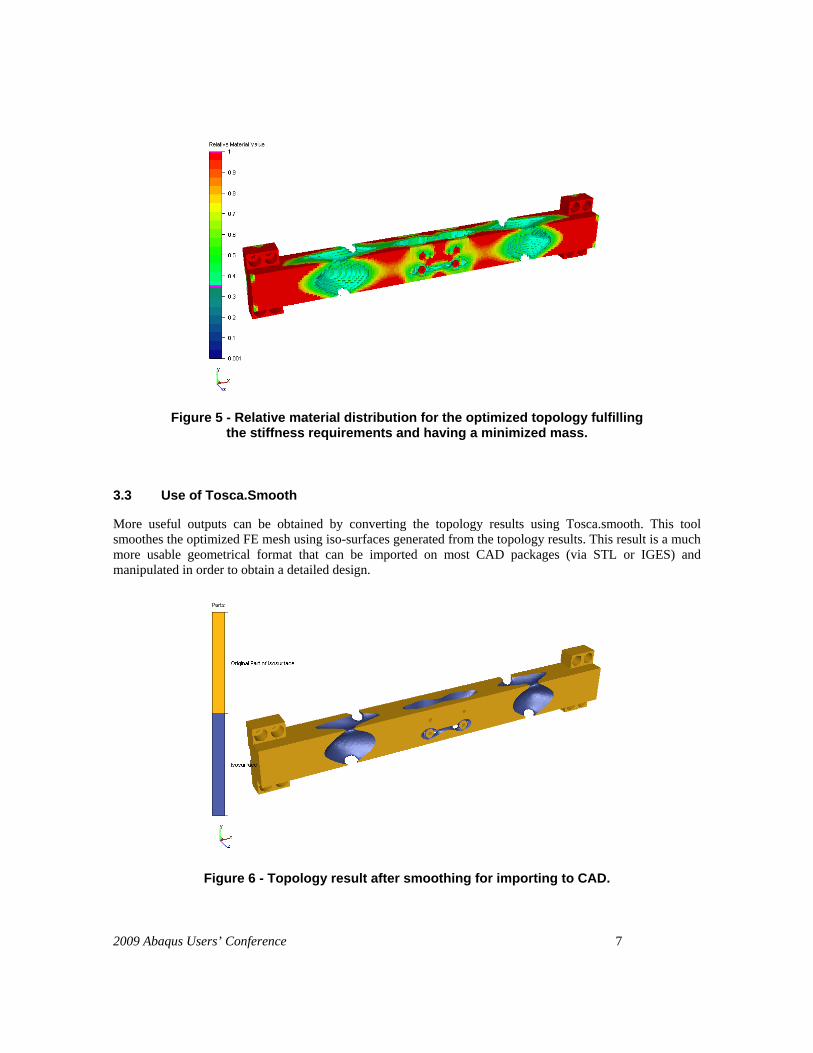
In the optimization 69,434 elements of 70,784 elements are chosen as design variables. The optimization run has been set up around three loadcase. On each of those three loadcases a target deflection has been specified together with a tolerance range as defined figure 4. The optimization then adjusts the design to the stiffness requirements and minimizing the mass by adding and removing material. The optimization converged with a an objective function on the minimum volume of 0.70, meaning that 30% of the initial weight has been removed in order to reach a solution that satisfies all 3 loadcases at the same time. The solution is presented from the Tosca.gui and shows a crude model where inefficient elements have been removed by the optimizer as illustrated in figure 5. It is possible to plot and superimpose all 3 loadcases and check the results against imposed targets.
My
Mx
2009 Abaqus Users’ Conference 7
Figure 5 - Relative material distribution for the optimized topology fulfilling the stiffness requirements and having a minimized mass.
3.3 Use of Tosca.Smooth
More useful outputs can be obtained by converting the topology results using Tosca.smooth. This tool smoothes the optimized FE mesh using iso-surfaces generated from the topology results. This result is a much more usable geometrical format that can be imported on most CAD packages (via STL or IGES) and manipulated in order to obtain a detailed design.
Figure 6 - Topology result after smoothing for importing to CAD.

8 2009 Abaqus Users’ Conference
3.4 Final component (design) and model validation
Following the import of the smoother geometry a final design can be quickly produced. An example of a compliant beam is shown next. A fully dimensioned drawing has been produced in order to allow the manufacturing of the component and relative inspection procedures.
Figure 7 - Detail sizing of the beam using topology optimization.
The detailed design has been strength checked prior manufacturing. This confirmed the feasibility of this approach and final deflections were still within the targeted values.
Following the manufacturing of the component a full validation has been performed on the beam in order to check that the deflections of the detailed design were within the initial targeted value. The validation proved successful.
Figure 8 - Validation of deflection (Loadcase 1).

2009 Abaqus Users’ Conference 9
3.5 Impact of stiffness requirements on optimized design
Additionally, the impact of the stiffness requirements and thereby the displacement constraints on the optimized design is examined in the following. The displacement constraints are considerable relaxed as shown in figure 9. Furthermore, as expected the mass is also considerable reduced due to the relaxed stiffness requirements. Figure 9 also shows that the displacement for the z-direction is initially too flexible but surprisingly the rotation around the x- and y-directions are too stiff and additional material is automatically removed in order to ensure the desired flexible for rotations around the x- and y-directions are fulfilled. At figure 10 the optimization iteration history for the design is shown indicating how the material is automatically removed for achieving the optimized design.
Figure 9 – Topology optimization convergence history for reduced stiffness requirements.
Figure 10 – Topology optimization iteration history for reduced stiffness requirements.

10 2009 Abaqus Users’ Conference
4. Shape optimization: Objectives and constraints
Shape optimization is mostly used at the end of the designing process. Typically, the objective function is to minimize stress concentrations, strain concentrations or minimize the damage due to fatigue. The non-parametric approach used in this work has been utilized for several years in the industry with great success. The gradient-less method has the advantages that it is solver independent, a tediously parameterization is avoided and it can also be applied using fatigue, non-linear, and contact modeling [6,7]. The main concept of the method is to use the positions of the surface nodes as design variables and move these in the normal direction of the surface e.g. to achieve a uniform stress-distribution. References and a more detailed description of the method are given in [7].
The non-parametric shape modifications in TOSCA are performed automatically in the Abaqus finite element deck (.inp) and each node may be displaced independently (see figure 11). One just defines an Abaqus node group (*NSET) in ones preferred preprocessing environment for Abaqus which then directly defines the surface for the optimization. This means that the use can apply existing Abaqus CAE models directly in shape optimization. Therefore, no shape basis vectors have to be defined and no time consuming morphing predefinitions are required by the user. For ensuring mesh stability and accuracy an adaption of the finite element mesh by internal mesh smoothing algorithms is applied in TOSCA.
Figure 11 – Non-parametric shape optimization workflow based directly upon Abaqus finite element input deck (.inp).
For shape optimization the following can be defined as objective:
Minimize the maximum stresses of several loadcases (consider as the traditional objective).
Minimize damage and thereby increase durability. The optimization workflow supports both in-house and commercial fatigue solvers. This allows one to consider complex loading histories and detailed material data in the simulation for the optimization.
Homogenization for a uniform contact pressure.
Minimize the maximum plastic strains.
Apply a mass constraint.

2009 Abaqus Users’ Conference 11
Manufacturing restrictions (the mesh does not have to be regular or symmetric):
Manufacturing constraints e.g. stampable design, drillable design, turnable surface, demoldable design (see also figure 12).
Symmetry constraints (plane, point, rotational and cyclic symmetry and linked symmetry between different surfaces).
Figure 12 – Manufacturing constraints for shape optimization.
5. Shape optimization example - Development of a plastic strain tolerant Compressive Strut
In this particular application we are testing the code capabilities against the simple problem of a buckling strut. The objective is to minimize the equivalent plastic stresses in the strut under an imposed deflection of 20mm which causes the strut to buckle.
The model consists of a simple geometry made of C3D8R elements and a few C3D4 elements.

12 2009 Abaqus Users’ Conference
5.1 Boundary conditions and Optimization objectives
The stay is fully constrained on one end. On the other end a displacement of 20mm is imposed, forcing the stay to buckle.
Optimization objective: 1. Minimize plastic stress (peak) at full bump (20mm travel). Constraints:
1. Maximum reaction load during the calculation: 4500N 2. Minimum peak reaction load: 3800N 3. Symmetry in the vertical plane 4. Maximum allowed width = 30mm (dotted line)
Figure 13 - Optimization objectives and model constraints (Shape optimization).
5.2 Optimization results (shape optimization)
The buckling load is recorded and the maximum plastic strains on the side faces of the stay and the transition surface between the stay and encastre are also monitored during each increment. A node set containing all nodes of the two parallel faces of the struts and the transition surface has been selected for the optimization as shown in figure 14a. Those nodes can move freely within a certain envelop. A symmetry condition along the axis of the strut has been imposed on this geometry as shown in figure 14b. The reaction forces can not directly be imposed as constraints in a shape optimization. Therefore, a volume constraint is defined which indirectly impose constraints on the reaction forces during the deformation. Figure 15 shows the maximum plastic strains and the reaction force history of different optimized structures obtained using three different volume constraints. Figure 15b shows that the design obtained having a relative volume constraint of 95% fulfils the reaction force constrains. Consequently, this design is analysed in detail in the following.
Encastre
Moving platform
Direction of imposed displacement

2009 Abaqus Users’ Conference 13
Figure 14 – (a) Design nodes for the shape optimization defined by an Abaqus node set. (b) Enforce symmetry constraint for the stay.
Figure 15 – Three optimized designs having different volume constraints. (a) The maximal plastic strain as a function of the optimization iterations.
(b) The reaction forces as a function of the imposed displacement.
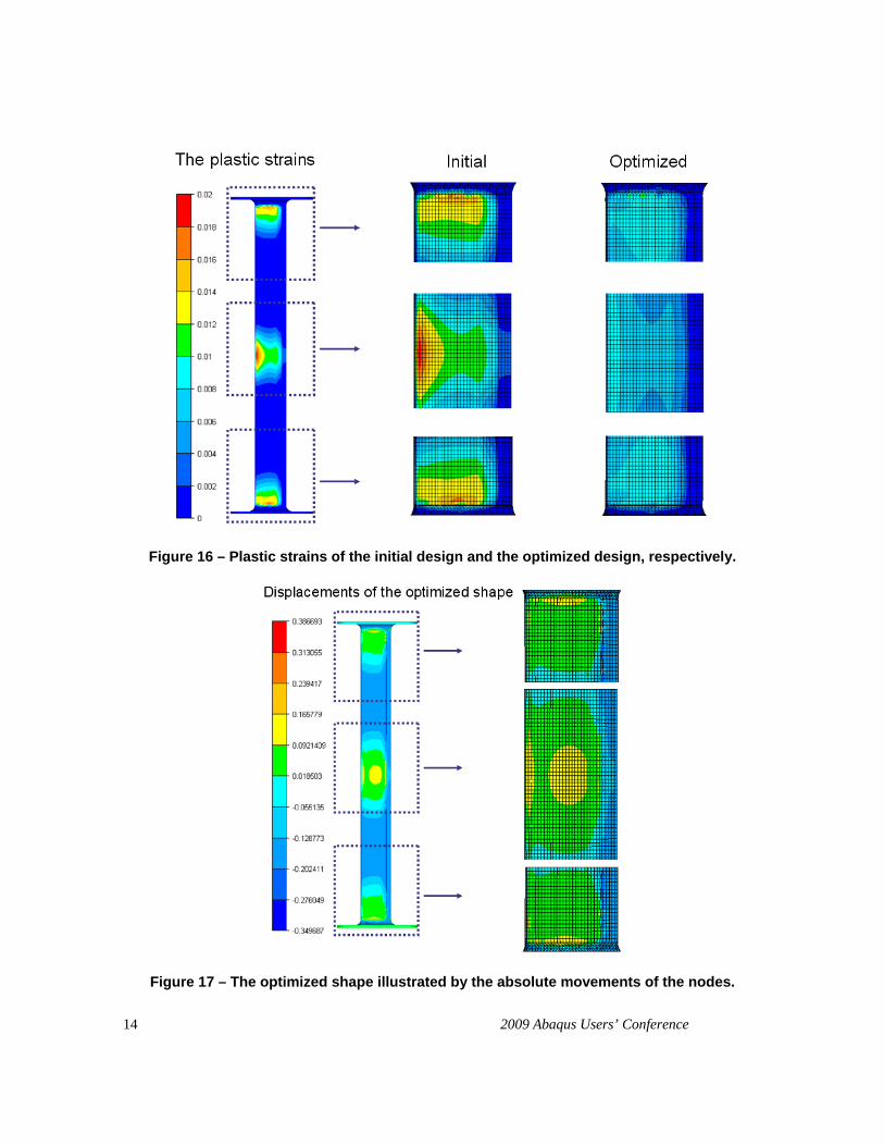
The optimization output shows that the location of maximum plastic strain changes from one optimization iteration to the next iteration, confirming that the solver is correctly dealing with its minimization. Plastic strain plots confirmed that the optimized stay has a reduced level of plastic strain, see figure 16. From figure 16 it can also be observed that the plastic strains in the most critical areas of the initial design are reduced with an average factor of more then 50% in the optimized design. Hence, the optimized design is more tolerant to overloads.
Figure 17 shows the movements of the nodes when modifying the shape from the initial design to the optimized design. It can be concluded that even small methodical modifications of the surface by optimization can lead to a significant reduction in the plastic strains.
14 2009 Abaqus Users’ Conference
Figure 16 – Plastic strains of the initial design and the optimized design, respectively.
Figure 17 – The optimized shape illustrated by the absolute movements of the nodes.
2009 Abaqus Users’ Conference 15
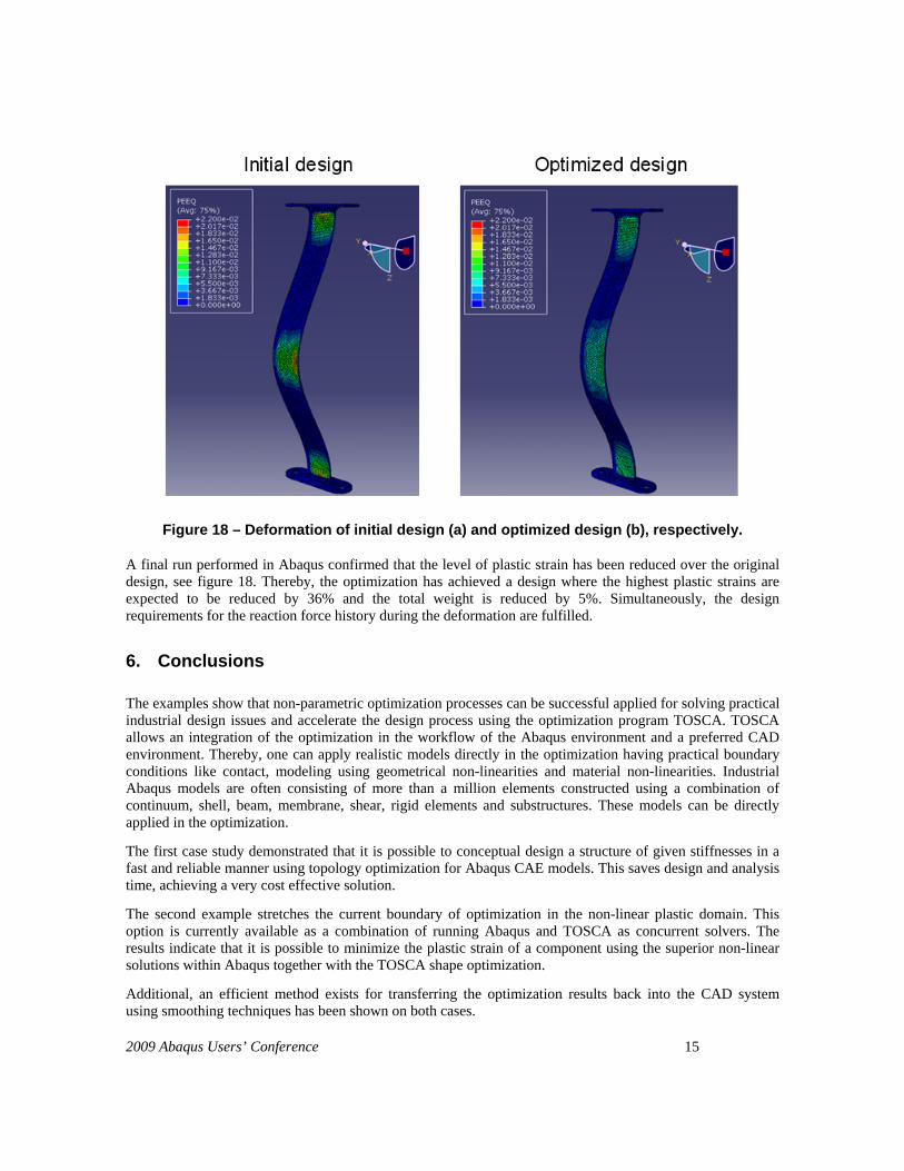
Figure 18 – Deformation of initial design (a) and optimized design (b), respectively.
A final run performed in Abaqus confirmed that the level of plastic strain has been reduced over the original design, see figure 18. Thereby, the optimization has achieved a design where the highest plastic strains are expected to be reduced by 36% and the total weight is reduced by 5%. Simultaneously, the design requirements for the reaction force history during the deformation are fulfilled.
6. Conclusions
The examples show that non-parametric optimization processes can be successful applied for solving practical industrial design issues and accelerate the design process using the optimization program TOSCA. TOSCA allows an integration of the optimization in the workflow of the Abaqus environment and a preferred CAD environment. Thereby, one can apply realistic models directly in the optimization having practical boundary conditions like contact, modeling using geometrical non-linearities and material non-linearities. Industrial Abaqus models are often consisting of more than a million elements constructed using a combination of continuum, shell, beam, membrane, shear, rigid elements and substructures. These models can be directly applied in the optimization.
The first case study demonstrated that it is possible to conceptual design a structure of given stiffnesses in a fast and reliable manner using topology optimization for Abaqus CAE models. This saves design and analysis time, achieving a very cost effective solution.
The second example stretches the current boundary of optimization in the non-linear plastic domain. This option is currently available as a combination of running Abaqus and TOSCA as concurrent solvers. The results indicate that it is possible to minimize the plastic strain of a component using the superior non-linear solutions within Abaqus together with the TOSCA shape optimization.
Additional, an efficient method exists for transferring the optimization results back into the CAD system using smoothing techniques has been shown on both cases.

16 2009 Abaqus Users’ Conference
7. References
[1] Svanberg, K. "The Method of Moving Asymptotes - A New Method for Structural Optimization", International Journal for Numerical Methods in Engineering", vol. 24, pp. 359-373, 1987.
[2] Bendsøe, M.P. and Sigmund, O. "Topology optimization: Theory, Methods and Applications", Springer-Verlag, Berlin Heidelberg, New York, 2003.
[3] FE-Design. "TOSCA User's Manual", FE-Design GmbH, Karlsruhe, Germany, 2008.
[4] Pedersen, C.B.W. and Allinger, P. "Industrial implementation and applications of topology optimization and future needs.", In: IUTUAM Symposium on Topological Design Optimization of Structures, Machines and Materials: Status and Perspectives (eds. M.P. Bendsøe, N. Olhoff and O. Sigmund), pp. 147-156, Springer, 2006.
[5] Clausen, P.M. and Pedersen, C.B.W. "Non-Parametric Large Scale Structural Optimization", In: ECCM 2006 III European Conference on computational Mechanics, Lisbon, Portugal, June 5-9, 2006.
[6] W. Huber, M. Fischer, and G. Himmler, Stress Reduction in an Interstage Air Seal using TOSCA (MSC.Construct) for Increasing the LCF Fatigue Life, MSC Virtual Product Development Conference, Bad Neuenahr , 24.-26. Juni, 2003
[7] R. Meske, J. Sauter and E. Schnack, Nonparametric gradient-less shape optimization for real-world applications, Strutural Multidisciplinary Optimization, 30, 201-218, 2005