optimization of accordion em calorimeter in...
TRANSCRIPT
GEM TN-92-257
Optimization of Accordion EM Calorimeter in GEM
Hong Ma, Mikhail Leltchouk Columbia University
November 22, 1992
Abstract:
The optimization of the accordion EM calorimeter for pointing, 1t0
rejection and for correcting the energy resolution for dead material is summarized. With strips of 4.55mm wide at the front part of the calorimeter, 8 angular resolution is about cro = (38.91.../E+0.5)mrad, and the 1t
0 rejection at 25 GeV is 85%. A massless gap integrated as part of the accordion can recover most of loss of resolution due to the dead material.
Optimization of accordion EM calorimeter in GEM
Hong Ma
Brookhaven National Laboratory
Mikhail Leltchouk
Columbia University
November 22, 1992
Abstract
•
The optimization of the accordion EM calorimeter for pointing, ir0 rejection and for
correcting the energy resolution for dead material is summarized. With strips of 4.55mm wide at the front part of the calorimeter, 9 angular resolution is about us= (38.9/VE + 0.5)mrad, and the ir0 rejection at 25 GeV is 85%. A massless gap integrated as part of the accordion can recover most of loss of resolution due to the dead material.
1 The accordion EM calorimeter
The accordion EM calorimeter proposed for the GEM detector uses lmm thick lead plates with liquid krypton as active medium. The projective geometry is achieved by varying the accordion bending angle in </> and using projective strips in T/· The sampling ratio is kept constant in depth.
The GEANT simulation code was developed by M. Seman. He produced a detail description of projective accordion geometry, used a special volume search algorithm, optimized the geometry for energy resolution and obtained the results on the main EM accordion calorimeter features. We modified this code for special tasks. Our work would not be possible without his effort in making this GEANT model.
Following the Baseline II, the cryostat starts at the radius of 95cm, and the active calorimeter starts at the radius of 105 cm. Dead material in front the calorimeter include the tracking detector, neutron absorber, cryostat wall, inactive liquid and calorimeter electronics. The total thickness in radiation length is about 1.1.
Excellent energy resolution of t7E/E = 5.6%/./E is obtained, as shown in Fig 1. However, the requirements to the EM calorimeter in the GEM detector include more
than just excellent energy resolution. To be specific, to search for H ..... "'!"'! decays with
1
crf/E = 5,633/ sqrt(E 6.4
6
5.6
5.2
4.8
4.4
4 0 10 20 30 40 50 60 70 80 90
Energy ( GeV)
Figure 1: Energy resolution of the accordion calorimeter
2
80 < MH < 120Ge V, angular resolution of the photons is essential for a good photonphoton mass resolution. The EM calorimeter has to provide high precision angular measurement of the photons, in case there are multi-vertices in the event, or the inner tracker fail to performance. Because the luminous region at the SSC has a large spread in Z but small in transverse directions, a position measurement of the shower in c/i may be sufficient while an angular measurement of the shower in TJ is needed. In addition, jets occasionally fragment into multi-photon clusters, even after strong isolation cut. Detailed information of the shower development helps to distinguish single and multi-photon showers. Both of the requirements (pointing and multi-photon rejection) call for a finely segmented calorimeter. The practical constraints are limited number of channels allowed, and complication of signal connections.
In this note we discuss first the effect of the dead material, and the integrated massless gap that will be used to recover the energy resolution. Then, two configurations of segmentation are considered. One has the regular tower structure, symmetric in c/i and TJ size, and longitudinally divided into two sections (8Xo + l 7Xo). The tower size is chosen to be t:;.c/i x t:;.T/ = 0.026 x 0.026. Four LKr cells are ganged together for one tower. This gives 240 towers in c/i. This configuration has less channel count, and provides some pointing and multi-photon rejection capabilities. Another configuration has three longitudinal segmentations, with the first one being short (3Xo) and finely segmented in TJ, and the remaining two having the same transverse segmentation as the first configuration. To reduce the channel count, the segmentation of the first section is asymmetric in c/i and T/· Each tower in the first section is subdivided in T/ into 6 strips, and strips of 6 consecutive towers in c/i are connected together in parallel. The strip size is 4.55mm, and the depth is one complete accordion cycle. The noise in such a readout channel is still relatively low, estimated to be about 10 MeV. The channel count is then increased by a factor of 1.5 relative to the first configuration. The middle section can be read out using a thin trace parallel to the electrode, probably routed to the back size of the calorimeter. The narrow strips are effective in distinguishing single and multi-photon clusters, by measuring the shower shape in the region where the photons are converted. This also provides a very precise measurement of position of the beginning of the photon shower. Combining with the long lever arm from the other two sections, the pointing resolution should be better too.
2 Massless gap
The amount of inactive material in front of EM calorimeter effectively increases at large incident angle because the cryostat walls have constant thicknesses. It is possible to decrease the influence of this dead material on the energy resolution using an active layer without absorber, so called massless gap, just after the dead material layer. There is a strong positive correlation between the shower energy deposits in dead layer and in this active gap. So fluctuations of energy deposition in dead material will demonstrate themselves in massless gap. This can decrease the degradation of the energy resolution connected with longitudinal shower fluctuation. We consider a massless gap integrated in accordion mechanical structure. The main amount of absorber material in this structure is a lead plate inside an absorber electrode. It is possible to replace this lead with a lighter material (such as G 10 or plastic) in the front part of accordion, just after cryostat wall.
3
A
40 x' Constant Mean
20 Si ma
0 3 3.2 3.4 3.6
EACT (5x5) B
40 x' Constant Mean
20 Si ma
0 3 3.2 3.4 3.6
c EACT (5x5)
x' 40 Constant Mean Si ma
20
0 3 3.2 3.4 3.6
EACT (5x5)
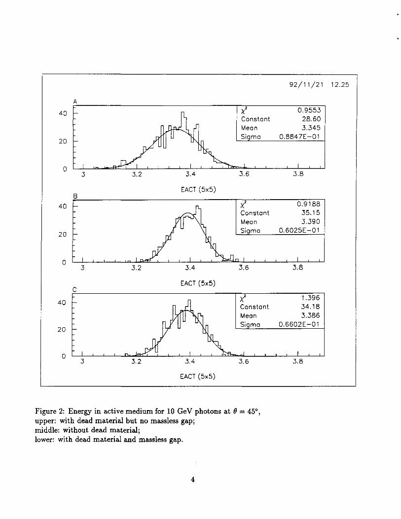
Figure 2: Energy in active medium for 10 GeV photons at()= 45°, upper: with dead material but no massless gap; middle: without dead material; lower: with dead material and massless gap.
4
92/11/21 12.25
0.9553 28.60 3.345
0.8847E-01
3.8
0.9188 35.15 3.390
0.6025E-01
3.8
1.396 34.18 3.386
0.6602E-01
3.8

20
g 17.5 ,_ .., :J -0 15 (I)
~ .E 12.5 4'
.s:; f- 10
7.5
5
2.5
2-depth towers 55/sqrt(E)+1,8
• t 1'=45°
strips + towers
38,9 / sqrt(E)+O,
0 0 0.04 0.08 0.12 0.16 0.2 0.24 0.28 0.32 0.36 0.4
1 /sqrt(E)
Figure 3: Angular resolution of tower and strip configuration.
5
This is a change only inside absorber electodes. Their surfaces, the readout electrodes and active LKr gaps are the same as in other accordion parts. We do not consider now the possible separation of readout electrode and additional electronic channels for separate massless gap readout. The signal from whole front part of projective accordion tower includes the signal from massless gap.
We've compared the massless gap thicknesses from 1 to 3 cm along the barrel calorimeter radius for 10 GeV photon showers at (J = 45° and found the best energy resolution recovery with 2.2 cm massless gap.
The events were generated with the Gaussian distributed Z vertex (<Tz = 4.2 cm) and uniform spray in (J and ¢ directions inside one tower. Then only events with maximum energy deposit in the "central" tower were chosen. To determine the energy resolution the signals from 5x5 towers (around this central tower) were summed.
On the Fig 2 one can see a comparison of the shower energy distributions for 10 Ge V photon at theta (J = 45°: A) upper plot - with cryostat, energy resolution - 8.4%/,/E; B) middle plot - no cryostat, energy resolution - 5.6%/VE; C) lower plot - with cryostat and 2.2 cm massless gap, energy resolution - 6.2%/,/E. At 45 degrees the total amount of dead material in front of active accordion part is about 1.6 radiation length along the shower direction. The energy resolution of 8.4%/,/E (with cryostat) degrades compare with 5.6%/,/E shown at Fig 1 for(}= 90°. The middle plot shows nonrealistic situation without cryostat just for comparison. One can see at lower plot that the resolution, as well as the signal amplitude, is partly recovered with the massless gap. An independent study by K. Shmakov [1] has reached similar conclusion.
But it is worth noting that this is only the start of EM calorimeter optimization. The dependence of the optimal massless gap depth on the shower energy should be considered. The combined optimization of the energy resolution recovery with massless gap and with the thinner lead plate in the forward region of the barrel calorimeter will be pursued together with the pi-zero rejection optimization.
3 Pointing resolution Position measurement with towers, using only the first moment weighted with energy, is not linear with the impact point. One way to correct it is to use logarithmic energy weighting, the other is to find explicitly the relation between the impact point and the linearly weighted position, sometimes referred to as s-curve correction. We have chosen the latter. The function used is Ximp = A• atan(B • Xm + C), where Xm is the calculated position, and Ximp is the impact position. A, B and C are parameters. At (} = 90°, the distribution is symmetric, therefore C=O. However, at forward angle, because the longitudinal division of the tower is at constant radius, and not perpendicular to the shower, the s-curve becomes asymmetric, then C "# O. The parameters are determined with events generated at Z=O, for each depth segmentation. Using these parameters, the angular resolution is determined for events generated with distributed Z vertices ( <Tz = 4.2cm ).
For the 2-depth tower configuration, the difference in position of the first and second section gives a measurement of the Z vertex. The angle is calculated using the mean shower position and Z vertex,
(1)
6
(2)
where ()mean is the mean () position using all depths, and 81, and 82 is the position using first and section section. k1,2 is determined from the MC events.
Similar procedure is applied to the strip configuration, where we find that using the strip and last depth gives the best angular resolution. Strips provides a very precise measurement of the shower position, because the small strip width and the shower size is small, transverse fluctuation is less at the beginning of the shower. At 25 GeV, the position resolution of the strips is 0.5mm. The lever arm between the strips and the last section is about 22cm.
Fig 3 shows the angular resolution for both configurations. A simple fit gives the following parameterization, for 2-depth towers,
55 <78 = ( v'E + 1.S)mrad (3)
and for strips, 38.9 )
<78 = ( v'E + 0.5 mrad (4)
Non-projective photons ( coming from Z-/. 0 ) tend to have worse angular resolution, because longitudinal shower fluctuations smear the position measurement. Some corrections can be made using the energy deposition in different depths. Larger statistics is needed, and this will be pursued in the future.
The angular resolution, to the first order, is independent of 8, provided propers-curve corrections are taken into account. Simulation shows that the angular resolution becomes somewhat better at small () angle (forward part of the barrel), because the deviation from projective angle due to the vertex spread is less significant. Fig 3 also shows the angular resolution with strips at()= 45° and 40 GeV. The Z-resolution, however, becomes worse at smaller () angle, because it relates to angular resolution in the following way, a z = R * <78 / sin2
( 8). A study by Yu. Efremenko [1] has shown that with energy resolution of <7E/ E =
5.5%/v'E EB 0.4%, angular resolution of <78 = (35/v'E + l)mrad would broaden the 'Y'Y mass width by a factor of 1.45. However, more sophisticated method can be applied. At 1033 cm-2s-1 luminosity where vertex multiplicity is not too high and vertices can be reconstructed, the good pointing resolution will allow us to find the correct vertex out of a few with high probability. The contribution to the mass width will then be negligible, because of the excellent position resolution. At high luminosity, a common vertex constraint for the two photons can also improve the angular resolution. Detailed studies are in progress.
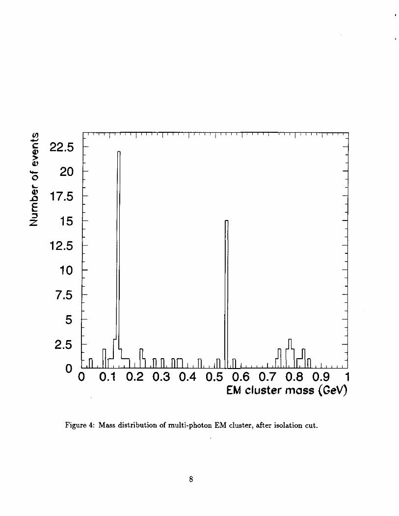
4 Multi-photon rejection A study by Vanyashin [1] shows that, of all the apparent single photons arising from multi-photons after an isolation cut, about 35% are single ir0 's, and others have higher mass including many 171 s decaying into photons. Fig 4 shows the mass distribution of these isolated EM clusters. In this study, we concentrate on the ir0 rejection as this is the most difficult one to reject.
7
"' ......, c
"' > "' -0 I..
"' .Q
E :::! z
22.5
20
17.5
15
12.5
10
7.5
5
2.5
0 0 0.1 0.2 0.3 0.4 0.5 0.6 0.7 0.8 0.9 1
EM cluster moss (GeV)
Figure 4: Mass distribution of multi-photon EM cluster, after isolation cut.
8
Using the towers of the calorimeter, two types of variables can be used to separate single photons and multi-photons: shower size and pointing. Multi-photon showers tend to have large shower size, as measured by the second moment of position using linear energy weighting. Due to the finite size of the towers, the calculated shower size depends on the impact position in the tower. Corrections are determined from single photon events.
If photons in a multi-photon shower are converted at different depths, the shower, when pointing back to the vertex, may miss the vertex. The pointing resolution in both </> and (} are calculated for photons.
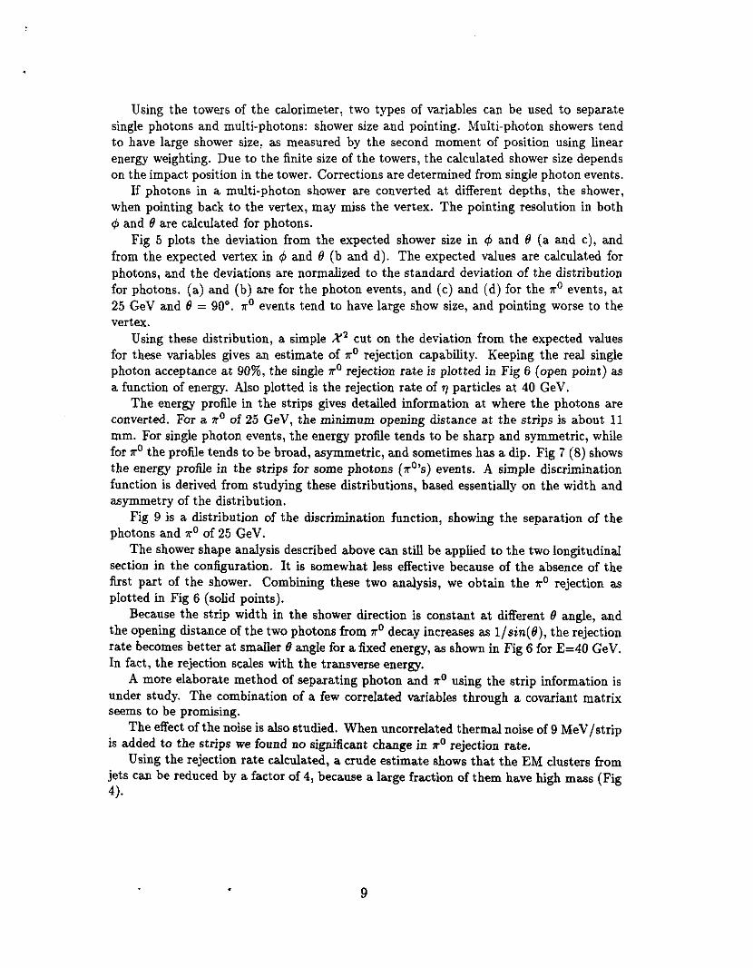
Fig 5 plots the deviation from the expected shower size in </> and (} (a and c), and from the expected vertex in </> and (} (b and d). The expected values are calculated for photons, and the deviations are normalized to the standard deviation of the distribution for photons. (a) and (b) are for the photon events, and (c) and (d) for the 11"
0 events, at 25 Ge V and (} = 90°. 7ro events tend to have large show size, and pointing worse to the vertex.
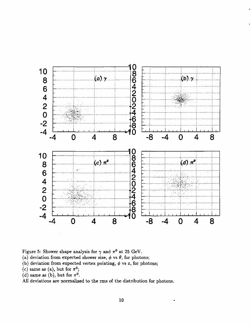
Using these distribution, a simple X 2 cut on the deviation from the expected values for these variables gives an estimate of 7ro rejection capability. Keeping the real single photon acceptance at 90%, the single 11"0 rejection rate is plotted in Fig 6 (open point) as a function of energy. Also plotted is the rejection rate of '1 particles at 40 Ge V.
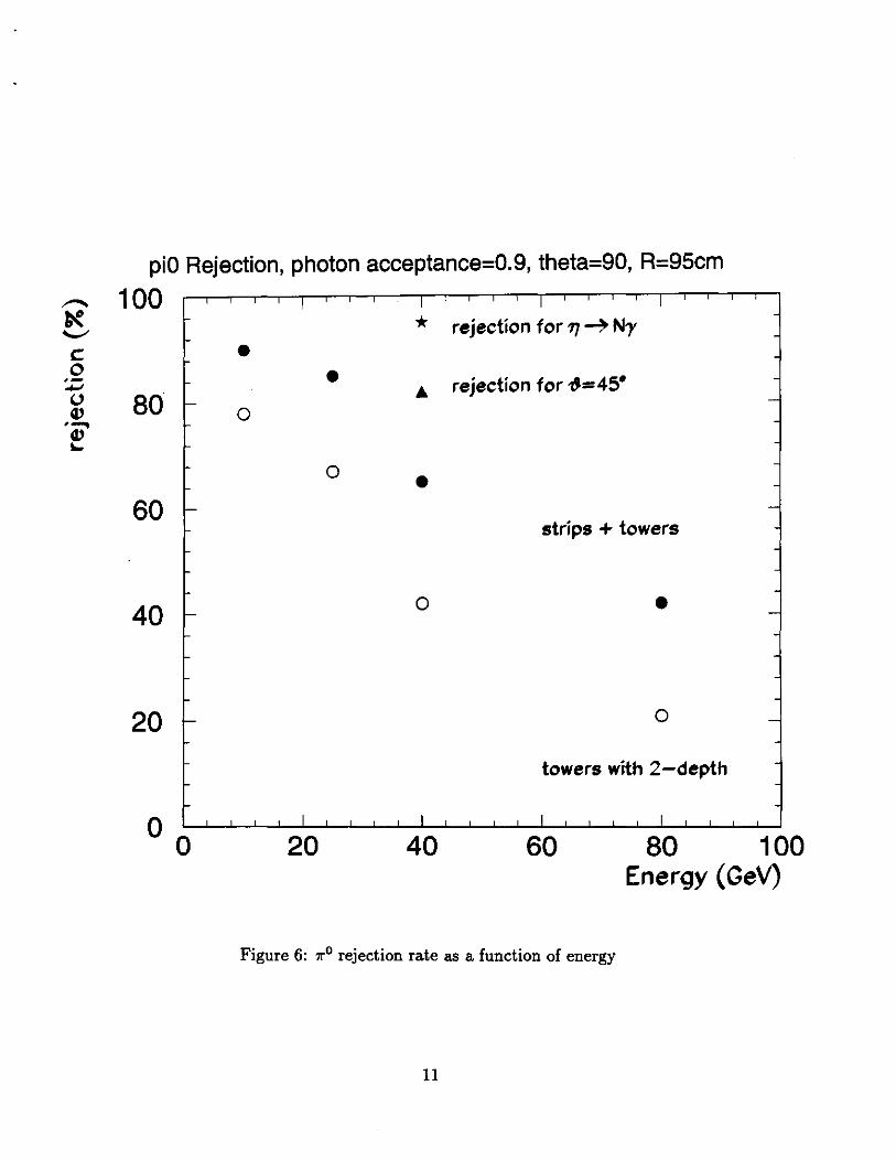
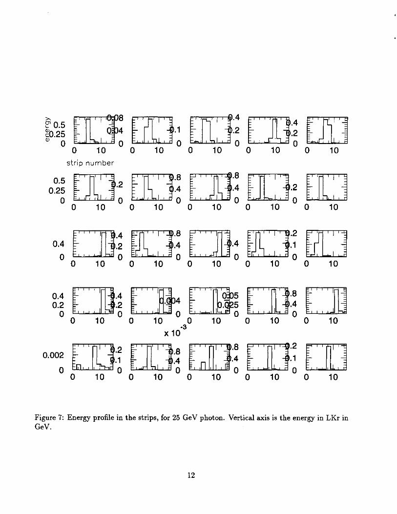
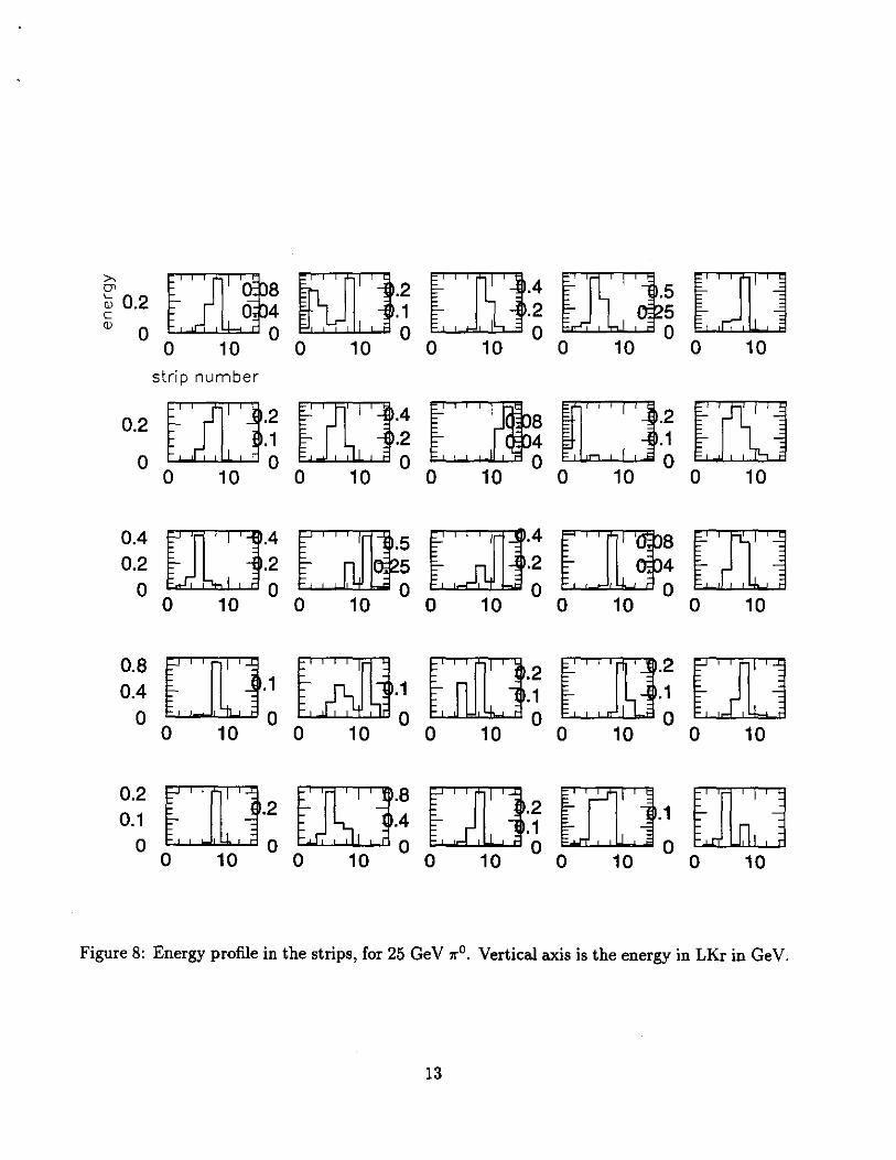
The energy profile in the strips gives detailed information at where the photons are converted. For a 11"0 of 25 GeV, the minimum opening distance at the strips is about 11 mm. For single photon events, the energy profile tends to be sharp and symmetric, while for 11"
0 the profile tends to be broad, asymmetric, and sometimes has a dip. Fig 7 (8) shows the energy profile in the strips for some photons ( 7r0 's) events. A simple discrimination function is derived from studying these distributions, based essentially on the width and asymmetry of the distribution.
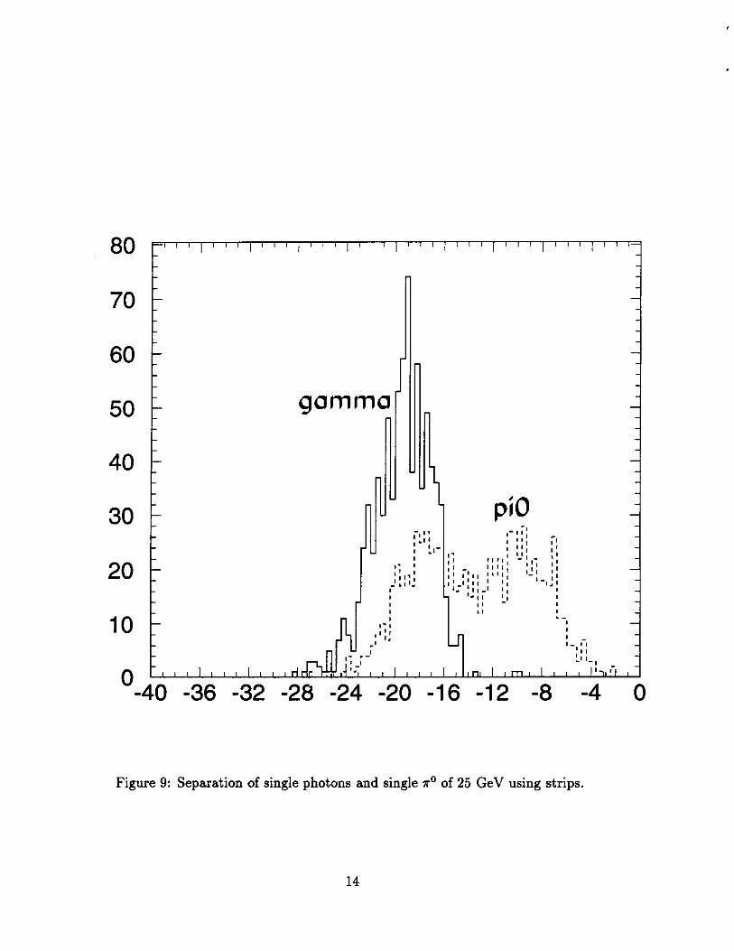
Fig 9 is a distribution of the discrimination function, showing the separation of the photons and 11"0 of 25 Ge V.
The shower shape analysis described above can still be applied to the two longitudinal section in the configuration. It is somewhat less effective because of the absence of the first part of the shower. Combining these two analysis, we obtain the ?ro rejection as plotted in Fig 6 (solid points).
Because the strip width in the shower direction is constant at different (} angle, and the opening distance of the two photons from 11"
0 decay increases as 1/ sin( 9), the rejection rate becomes better at smaller (} angle for a fixed energy, as shown in Fig 6 for E=40 Ge V. 1n fact, the rejection scales with the transverse energy.
A more elaborate method of separating photon and 7ro using the strip information is under study. The combination of a few correlated variables through a covariant matrix seems to be promising.
The effect of the noise is also studied. When uncorrelated thermal noise of 9 Me V /strip is added to the strips we found no significant change in 11"0 rejection rate.
Using the rejection rate calculated, a crude estimate shows that the EM clusters from jets can be reduced by a factor of 4, because a large fraction of them have high mass (Fig 4).
9
10 8 6 4 2 0
-2 -4
10 8 6 4 2 0
.--~~~~~~~~,o
··············•············ ······························ 8 . .. . ..... . (0)1 . .... . 6
............. . ....................... 4 2 ............... .. ... .. . ......... 0
'.--· . : 2 ···········.:·;;:::············,-·········· .....•............
. ·¥ti~ r•••r i ..__._.......__._.._-'---'___.___.__.__._ ......... _,_r10
0 4 8 -4
.--~~~~~~~~,o
··:··:·:···::r::··::·:·::··.:1<~>:~ .. :::::·:::··:··: ~ ................ ' ............. : ............... : ............ 4
: ; . 2
-4 0 -4 0 4 8
Figure 5: Shower shape analysis for I and 7ro at 25 GeV.
............. .{b).r ................. . . .
--·--·---·····-~··-·······-~·-···· ·--··-·-·············· . . . .
... : ::: :.~~~:~:.:: :: . :. :: ::: : :::
..... -··. -· ................ ··.' .... -...................... .
... -.. --.. --.. -~ .. -........ ~-..... . . . . . . . ....... -. . . -... -
... ·········---~··········-~·-······---- ............ ···--
-8 -4 0 4 8
... ~ ... --. ---. --~ --.. --.. --. ~- .......... -~. -...... . . . 'f 'J. . ... : .............. · ........... ~d,, .. 11 .. : ............ : .... .
.. -~- ..... ·-·· ---~ .... · ...•... J·. --- --- ·.--. -~- ........... ~-- .. . ;.··-
::: [::::::::::: :[ :;:: -~~~;~~f:0~:~. ;:: : ;; :.: : : : : : : : : : [::::: ... ; ... , .. ---·-+.; .-.. ~.:,:;,.-~:;_,.' ........ ."--~- .... -·. --- . :- . -- .
. . ---~---··· ··----~-- --_-·-·· :.~ ..... -·--------~--- ..... -.. -~-. -- . . . . . . . . ... ;. .. ··-··. ·····:·· ........ ····:· ·-· ..... ···i·· .......... ;. .... . . . . . . . . . . . ...•............... ······. ··~··· ................. .
-8 -4 0 4 8
(a) deviation from expected shower size, q, vs 0, for photons; (b) deviation from expected vertex pointing, q, vs z, for photons; (c) same as (a), but for 7r0 ;
( d) same as (b ), but for 7r0•
All deviations are normalized to the rms of the distribution for photons.
10
piO Rejection, photon acceptance=0.9, theta=90, R=95cm
100 * rejection for 17 ~ N-y
• 80
• A rejection for ~=45•
0
0 • 60
strips + towers
40 0 •
20 0
towers with 2-depth
0 0 20 40 60 80 100 Energy (GeV)
Figure 6: ir0 rejection rate a.s a. function of energy
11
>,
ll UD~ [[J.4 []].4 [[] 2' 0.5 ~.25 .2 .2 (J)
0 0 0 10 ° 0 10 0 10 0 10 0 10
strip number
0.5
DD·~ [[J.8 []J.8 [[]-~ [[] 0.25 .4 .4
0 0 0 0 10 0 10 0 10 0 10 0 10
EJlJ.4 f[J.8 DJ~ f[J.2 fl[] 0.4 .2 .4 .1
0 0 10 ° 0 0
0 10 0 10 0 10 0 10
0.4 []1:~ []}4 ED~ [][]·8 Dil 0.2 .4 0 0 0 0
0 10 0 10 0 10 0 10 0 10 -3
x10
rn-2 [[]·8 [JJ.8 rn·2 rn 0.002 .1 .4 .4 .1 0
0 10 ° 0 0 0 0 10 0 10 0 10 0 10
Figure 7: Energy profile in the strips, for 25 GeV photon. Vertical axis is the energy in LKr in GeV.
12
"' OJJ8 run-2 [[1.4 [[LJ~ rn ry
~ 0.2
6 .1 .2 c Q)
0 0 0 0 10 0 10 0 10 0 10 0 10
strip number
0.2 [[]·2 fl[J.4 ra. D·2 [[] .1 .2 .1 0 0 0 0
0 10 0 10 0 10 0 10 0 10
0.4 ED.4 EB~
[]JJ.4 ED~ [[] 0.2 .2 .2 0 0 0
0 10 0 10 0 10 0 10 0 10
0.8 rn ~ Eb1bl-~ [)]·2 [IJ.2 [][] 0.4 .1 .1 0 0 0
0 10 0 10 0 10 0 10 0 10
0.2 rn·: DSJ.8 [[]·2 [LI]-~ EIGJ 0.1 .4 .1 0
0 10 ° 0 10 ° 0 10 0 10 0 10
Figure 8: Energy profile in the strips, for 25 GeV 71"0
• Vertical axis is the energy in LKr in GeV.
13
80
70
60
50
40
30
20
10
0-40 -36 -32
gamma
' ' '. ' ''• ' '· ·' . _, ' •:
piO .- I~: I Ill I Ill
·.~ ,,,.1, '-'1 -,., 1 1 - I I I I 1 I~ I I I I I: I I I ~I I I I_ I I I _1 1 I I I I I ·~
I., 111 _I I I
.. 11 ~·
" "
-28 -24 -20 -16 -12 -8
-, ' ' 1- ,-,
'" ~· ·-. '
-4
Figure 9: Separation of single photons and single 11"0 of 25 Ge V using strips.
14
;
0
5 Conclusion With careful design of the front part of the calorimeter, the effect of the dead material in front of the calorimeter can be minimized. Comparing the two configuration of the segmentations, we have found great advantages of having 3 longitudinal divisions as well as adding fine transverse strips in T/: improving the angular resolution by 50% and increasing rr0 rejection. Both of these capabilities are crucial in search for H --> 'YI.
References [l] GEM note, Calorimeter simulation meeting, GEM Collaboration Meeting at BNL,
Nov 1992.
15