optimization of kitchen scale design by using...
TRANSCRIPT
OPTIMIZATION OF KITCHEN SCALE DESIGN BY USING BOOTHROYD-DEWHURST DFA METHOD
MUHAMMAD ASYRAF BIN MOHD NIZA
Report submitted in partial fulfilment of the requirements for the award of the
degree of Bachelor of Degree in Mechanical Engineering with Manufacturing
Engineering
Faculty of Mechanical EngineeringUNIVERSITI MALAYSIA PAHANG
NOVEMBER 2009
SUPERVISOR’S DECLARATION
I hereby declare that I have checked this project and in my opinion, this project is
adequate in terms of scope and quality for the award of the degree of Bachelor of
Mechanical Engineering with Manufacturing Engineering.
..........................................
Hadi Bin Abdul Salaam
Supervisor/Lecturer
Date:
STUDENT’S DECLARATION
I hereby declare that the work in this project is my own except for quotations and
summaries which have been duly acknowledged. The project has not been accepted for
any degree and is not concurently submitted for award of other degree.
..........................................
Muhammad Asyraf Bin Mohd Niza
ME06014
Date: 3 November 2009
DEDICATION
For my Father and Mother.
Mohd Niza Bin Abdul Aziz
Faridah Akmal Binti Ghazali
ACKNOWLEDGEMENTS
I am grateful and would like to express my sincere gratitude to my supervisor MrHadi Bin Abdul Salaam for his germinal ideas, invaluable guidance, continuous encouragement and constant support in making this research possible. He has always impressed me with his outstanding professional conduct, his strong conviction for engineering and technology, and his belief that a bachelor degree program is only a start of a life-long learning experience. I appreciate his consistent support from the first day I applied to graduate program to these concluding moments. I am truly grateful for his progressive vision about my training in engineering and technology, his tolerance of my naïve mistakes, and his commitment to my future career. I also sincerely thanks for the time spent proofreading and correcting my many mistakes.
My sincere thanks go to all my labmates and members of the staff of the Mechanical Engineering Department, UMP, who helped me in many ways and made my stay at UMP pleasant and unforgettable. Many special thanks go to member of engineering research group for their excellent co-operation, inspirations and supports during this study.
I acknowledge my sincere indebtedness and gratitude to my parents for their love, dream and sacrifice throughout my life. I acknowledge the sincerity of my brother and sister for their sacrifice, patience, and understanding that were inevitable to make this work possible. I cannot find the appropriate words that could properly describe my appreciation for their devotion, support and faith in my ability to attain my goals. Special thanks should be given to my fellow friends and junior. I would like to acknowledge their comments and suggestions, which was crucial for the successful completion of this study.
ABSTRACT
This thesis deals with design optimization of existing produt (kitchen scale) for better improvement by using Boothroyd-Dewhurst Design for Assembly (DFA) Methodology. The objective of this thesis is to generate a new design of kitchen scale that consider the matter of parts elimination, cost estimation, and design efficiency (DE). The thesis describes the Boothroyd-Dewhurst DFA method in obtaining the suggestion for redesign of the parts evaluated. The strategy of evaluating the existing design is first to choose the available product in the market in order to solve a problem. The product choosen were then disassembled into several families or sub-assemblies. This is forunderstanding how the parts functioning during normal operating mode. After that, each parts been critics and study if there is a chances for redesign. Finally, referring to suggestion from Boothroyd-Dewhurst DFA method, the new parts design are generated. From the results, it is observed that the analysis using Boothroyd-Dewhurst DFA method is easier for determine the parts to be redesign. The acquired results utilizing the new design are much more efficient then the original design after the evaluation due to maximum reduction of components like screw and fasteners. However, reducing the parts not always meant that the design are being optimize. There are much more things to consider like the manufacturing process required to produce the new design. Therefore, the concept of concurrent engineering (CE) is important to have designers and production engineers way of thinking in redesigning the new parts or components.
ABSTRAK
Tesis ini membentangkan penyelidikan menggunakan kaedah Design for Assembly (DFA) Boothroyd-Dewhurst dalam mengoptimumkan rekabentuk produk sedia ada di pasaran. Objektif tesis ini ialah menghasilkan rekabentuk baru bagi produk penimbang dapur dengan mengambilkira isu bilangan komponen, anggaran kos, dan kejituan rekabentuk. Tesis ini melihat bagaimana kaedah DFA Bothrooyd-Dewhurst begitu berkesan dalam mencadangkan komponen yang berpotensi untuk diubah-suai. Strategi dalam menilai potensi rekabentuk sedia ada bermula dengan pemilihan produk yang sesuai dan berpotensi untuk dibangunkan. Kemudian, produk yang dipilih akan di leraikan mengikut kategori yang tertentu bagi memudahkan proses pemahaman cara produk berfungsi. Selepas itu, setiap komponen akan dikaji dan dikritik mengenai cara pemasangan dan pengendaliannya merujuk kepada kaedah DFA Boothroyd-Dewhurst tadi. Akhirnya, proses rekabentuk komponen baru dapat dilaksanakan hasil dari data dan cadangan daripada kaedah DFA Boothroyd-Dewhurst. Daripada kajian ini, dapat dikatakan bahawa kaedah DFA boothroyd-Dewhurst amat berkesan dan dapat memudahkan proses rekabentuk komponen dalam mengoptimumkan prestasi sesebuah produk. Keputusan akhir menunjukkan kos produk, bilangan komponen dan kejituan rekabentuk dapat dioptimumkan dengan cara pengurangan komponen penyambungan seperti skru dan pin. Namun, pengurangan bilangan komponen dalam proses rekabentuk baru tidak semestinya bermakna ianya dapat mengoptimumkan sesuatu produk itu. Hal ini kerana, banyak lagi faktor yang perlu diambil kira dalam menghasilkan produk baru seperti proses pembuatan komponen baru. Oleh itu, konsep ‘Concurrent Engineering’(CE) itu sendiri amat penting dimana pandangan dan pemikiran seperti seorang jurureka dan jurutera pengeluaran harus diberiperhatian selari dengan proses ubah-suai dan rekabentuk produk baru.
TABLE OF CONTENTS
Page
SUPERVISOR’S DECLARATION ii
STUDENT’S DECLARATION iii
ACKNOWLEDGEMENTS iv
ABSTRACT v
ABSTRAK vi
TABLE OF CONTENTS vii
LIST OF TABLES viii
LIST OF FIGURES ix
LIST OF SYMBOLS x
LIST OF ABBREVIATIONS xi
CHAPTER 1 INTRODUCTION
1.1 Introduction 1
1.2 Project Background 2
1.3 Problem Statements/Purpose of Studies 2
1.4 Objective of Studies 3
1.5 Scope of Studies 4
1.6 Report Arrangement 4
CHAPTER 2 LITERATURE REVIEW
2.1 Introduction 6
2.2 Product Design Environment 6
2.2.1 History of Product Development Process 7 2.2.2 Concurrent Engineering (CE) 82.3 Total Cost Reduction 9
2.3.1 Cost Estimation 10 2.3.2 Information Content and Total Cost 11
2.3.3 Strategies for Reducing Information Content 112.4 Part Elimination Strategies 12
2.4.1 Candidate for Elimination 12 2.4.2 Consolidate Parts into an Integral Design 14
2.4.3 Eliminate Separate Fasteners 162.4.4 Reduce the Number of Theoretical Parts 172.4.5 Create Hybrid Parts 172.4.6 Standardize 19
2.5 Assembly Design 20
2.5.1 Assembly Cost Drives 20 2.5.2 Component Handling 21
2.5.3 Component Insertion 242.5.4 Component Securing 252.5.5 Separate Operations 25
2.6 Component Design 26
2.6.1 Process-Specific Design 26 2.6.2 Design for Plastic Injection Molding 28
2.6.3 Design for Machining 302.7 Various Method of DFA 31
2.7.1 Boothroyd-Dewhurst DFA Method 31 2.7.2 Lucas Hull DFA Method 36
2.7.3 Comparing Various Method of DFA 382.8 DFA Tools and Software 39
2.8.1 Boothroyd-Dewhurst DFA Software 39 2.8.2 DFM Concurrent Costing Software 422.9 Previous Research on DFA 44
CHAPTER 3 METHODOLOGY
3.1 Introduction 46
3.2 Design of The Study 46
3.3 Framework of The Study 49
3.3.1 Identifying and Selection of Product 49 3.3.2 Parts disassemblies 49
3.3.3 Measuring and CAD Modeling 503.3.4 Boothroyd-Dewhurst DFA Manual Evaluation 503.3.5 Generate a New Design 56
CHAPTER 4 DESIGN EVALUATION AND MODELING
4.1 Introduction 57
4.2 Product Description 58
4.2.1 Product Specification 584.3 Orginal Design Evaluation 60
4.3.1 Parts Quantity, Function, and Materials in the Original Design
62
4.3.2 Criticism for All Part Component 754.3.3 Assembly Operation Sequences 764.3.4 Current Design Analysis 794.3.5 Estimation of Assembly Cost for The Original Design 814.3.6 Estimated Assembly Cost and Design Efficiency for The Original Design
82
4.3.7 Selection of Parts Redesign 834.4 Product Redesign Evaluation 84
4.4.1 Generate New Design 844.4.2 Estimation of Assembly Cost for the New design 884.4.3 Design Efficiency for the New Design 89
4.5 Comparison Between Original And New Design 90
4.6 Summary 91
CHAPTER 5 EXTENSIVE ANALYSIS ON PART DESIGN
5.1 Introduction 925.2 Assumptions 935.3 Material Selection 935.4 MPI Simulation Analysis 975.5 MPI Simulation Comparison 1005.6 Summary 100
CHAPTER 6 CONCLUSIONS AND RECOMMENDATIONS
6.1 Conclusions 1016.2 Recommendations for the Future Research 103
REFERENCES 104
APPENDICES
A Final Year Project Gantt Chart 107
B Final Year Project Flow Chart 109
C Exploded view of Kitchen Scale Assembly 111
D Exploded view of weight mechanism Assembly 112
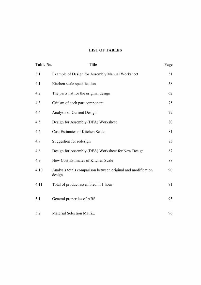
LIST OF TABLES
Table No. Title Page
3.1 Example of Design for Assembly Manual Worksheet 51
4.1 Kitchen scale specification 58
4.2 The parts list for the original design 62
4.3 Critism of each part component 75
4.4 Analysis of Current Design 79
4.5 Design for Assembly (DFA) Worksheet 80
4.6 Cost Estimates of Kitchen Scale 81
4.7 Suggestion for redesign 83
4.8 Design for Assembly (DFA) Worksheet for New Design 87
4.9 New Cost Estimates of Kitchen Scale 88
4.10 Analysis totals comparison between original and modification design.
90
4.11 Total of product assembled in 1 hour 91
5.1 General properties of ABS 95
5.2 Material Selection Matrix. 96
LIST OF FIGURES
Figure No. Title Page
1.1 Summary of the outline study 6
2.1 The “over the wall” design method 7
2.2 Benefits gained from implementing concurrent engineering in 150 surveyed companies
9
2.3 Price structure of a typical manufacturing enterprise. Commonly Used figures of merit include the processing overhead ratio (direct cost/material cost) and the operational overhead ratio (selling price/direct cost). For many firms, these ratios have numerical values of about 3. Hence, to make a reasonable profit, selling price needs to be approximately 9 times material cost (Chow, 1978)
10
2.4 Plot of total assembly time verses dimensional information content
11
2.5 Achieving an efficient part count depends on a variety of factors. If development time is critical, it may be better to have more parts that are easier to tool and have shorter lead times. If development time is less important, fewer parts, even they are more complex, will usually result in less total information content. The optimum part count may not correspond to the theoretical minimum, however, if part geometry becomes too complex. (Stoll W.H, 1999)
13
2.6 In integral design, many separate parts are consolidated into one. (a) Two metal coil springs together with nesting, handling, and other assembly problems are eliminated by the molded plastic cantilever leaf springs. (b) Molding the cover and enclosure as one part using a “living” hinge eliminates core pulls, hinge hardware, and alignment problems. (Stoll W.H, 1999)
15
2.7 Four-piece riveted assembly redesigned as a two-piece assembly by integrating the fastening function into higher level parts.(a) Original riveted design. (b) Redesign using formed features. (Stoll W.H, 1999)
17
2.8 Replacing an assembly with the hybrid part: (b) cross-sectional view of the original two-piece extruded aluminium vane and extruded rubber seal assembly: (c) cross-sectional view of co-extruded hybrid plastic vane. (Stoll W.H, 1999)
18
2.9 Reduce information content by postponing descretization. (a) The terminals are fabricated as a sheet metal stamping and assembled as a unit. (b) After insert molding, the connecting piece is cut away. (Stoll W.H, 1999)
18
2.10 In general, for ease of part handling, a designer should attempt to : (Boothroyd, et. al., 2002)
22
2.11 (Boothroyd, et. al., 2002) 23
2.12 Classification of commonly employed manufacturing processes 27
2.13 (a) Shrinkage defects occur due to variations in thermal mass in different regions of a plastic injection molded part. (b) A uniform wall thickness (nominal wall) combined with generous fillets and radii help avoid shrinkage problems
28
2.14 Weld lines form when the plastic flow divides into two or more paths. (a) This gate location causes a weld line to form in a critical region of the part. (b) This gate location causes the weld line to form in a less critical region
29
2.15 Boothroyd and Dewhurst DFA analysis (Boothroyd, et. al., 2002) 33
2.16 Screenshot of Boothroyd and Dewhurst DFA Software interface 39
2.17 Result Box 40
2.18 Important tools and box in the Boothroyd-Dewhurst DFA software [Structural Chart (1), Question Panels (2)-(6) and Result Box (7)]
41
2.19 Print screen of BDI-DFM Concurrent Costing Software 42
3.1 Framework of the study 48
3.2 Boothroyd-Dewhurst DFA Manual Handling Table 52
3.3 Boothroyd-Dewhurst DFA Manual Insertion Table 53
3.4 Selected manual handling time standards, seconds (parts are within easy reach, are no smaller than 6mm, do not stick together, and are not fragile or sharp)
54
3.5 Selected manual insertion time standards, seconds (parts are small and there is no resistance to insertion)
55
3.6 Selected separate operation times, seconds (solids parts already in place)
56
4.1 Kitchen scale photo and CAD drawing. (a) Picture illustrates the photo of Kitchen Scale in the market (b) Picture illustrates the 2D dimension of overall products (131x151mm) (c) Picture illustrates the isometric view of CAD drawing (d) Picture illustrates the transparent view into the inner components and assembly of the kitchen scale
58
4.2 Product Tree of Kitchen Scale original design 61
4.3 Picture and Dimension of all Kitchen Scale Parts 63
4.4 Description of Redesign Part 84
5.1 Thermoplastics Cost/Performance Diagram 94
5.2 Thermoplastics Impact/Toughness Guide 94
5.3 Thermoplastics Ductile/Brittle Guide 95
5.4 Estimated (a) filling time for original scale design is 1.279 second and (b) cooling time is 46.16 second while (c) filling time for original front cover design is 2.408 second and its (d) cooling time is 107.9 second
97
5.5 Estimated (a) filling time for new integral design is 1.795 second and (b) cooling time is 61.92 second
99
5.6 Comparison between the total estimated cycle time for both old and new design
100
LIST OF SYMBOLS
Ed Functional efficiency
Ema Design efficiency
Nmin Theoretical minimum number of parts
Ta Basic assembly time = 3 second
T h Handling time
Tma Estimated time to complete the assembly of the product
Ti Insertion time

LIST OF ABBREVIATIONS
ABS Acrylonitrile-Butadiene-Styrene
AEM Assemblability Evaluation Method
ASF Assembly Sequence Flowchart
CAD Computer-aided design
CAE Computer-aided engineering
CE Concurrent Engineering
CFE Candidate for Elimination
DFA Design for Assembly
DFM Design for Manufacture
DFMA Design for Manufacture and Assembly
MPI MoldFlow Plastics Insight
PC Polycarbonate
PP Polypropylene
PPO Polyphenylene Oxide
CHAPTER 1
INTRODUCTION
1.1 INTRODUCTION
Developing successful product requires the ability to predict, early in the
product development process, the life cycle impact of design decisions. Any misjudges
can leads to poor product designs that may cause unforeseen problems and excessive
costs. Cost to redesign at this late stage can be prohibitive. Sometimes companies must
simply accept higher manufacturing costs and reduced product effectiveness resulting
from early design errors.
Even for a product that has been already available in the market, product
improvements are required for survival from every competition from other companies
that are in the same business. Improvement can be done by optimizing a design itself, or
production process for manufacturing and assembly.
This chapter provides an overview of the project of Product Design and
Optimization of Kitchen Scale with using Design for Assembly (DFA) Method.
Generally, problem statement briefly discuss about how the product improvement are
important to highly demand product in market.
In this chapter, an overview of the background, objectives and scope of this
project are reviewed. Basically, the objective of this study is to redesign a new selected
product for a better design and lower production cost. Here, the DFA Method has been
applied to analyze the original product (Kitchen Scale). Lastly, in this chapter, the
overall thesis outlines are review and discussed in general.
2
1.2 PROJECT BACKGROUND
In recent years, research in the area of design for manufacturing and assembly
has become very useful for industries that are considering improving their facilities and
manufacturing methodology. In manufacturing industries, manufacturers focused on the
quality and productivity of the product. To increase the productivity of the product,
manufacturing companies and researchers have developed many design decision
support tools referred to as Design for X (DFX) methodologies. The ‘X’ in DFX
represents any one of a variety of design considerations occurring throughout the
product life cycle, such as quality, manufacturing, production, or environment. A DFX
decision support tool can take many forms. It could be procedure or a set of guidelines
on paper, or it could be a computer program that performs various types of analyses
resulting in cost, manufacturability, or performance estimates, which are then used by
the designer in making decisions.
Design for Manufacturing (DFM) and Design for Assembly (DFA) are two of
the most common and popular DFX tools. Traditionally, DFA methods evaluate the
ease of assembly, and DFM methods evaluate the feasibility and cost of manufacturing
the product at the operation level Bralla (1986), Anderson (1990), Corbett et al. (1991),
and Boothroyd et al. (2002) provide detailed discussions on manufacturability and
design.
1.3 PROBLEM STATEMENTS/ PURPOSE OF STUDIES
As kitchen scale is widely used by customer in the household appliance in the
market nowadays, the product life volume of this product must be high due to high
demand by the user. Thus, any cost reduction in kitchen scale production can be very
significant to the manufacturer in term of profit and production cost.
This studies is to redesign a kitchen scale for improvement in term of product
design and optimization in assembly process for a production, by using a one of many
design decision support tools referred to as Design for Assembly (DFA) methodology.
3
For the original product (datum), kitchen scale consists of 24 components
including screws and other type of fasteners. While to assemble the component of
kitchen scale, there have problems that occur such as difficult to assemble the
component because of having the different types and sizes of fasteners. The material of
parts that been used and the process of making one part also affected the cost to
manufacture the products.
Continuous development of kitchen scale can lead to improvement of
manufacturing and assembly process, thus enhance rapid development of technology in
manufacturing industry.
1.4 OBJECTIVE OF STUDIES
The main objective of this study is to analyze the selected product by using DFA
method and propose potential alternative design for improvement in term of ease of
assembly, cost estimates, and highly design efficiency. Besides that, the other objectives
of the study are:
i. To design and improve existing design by using DFA method and
observation upon information content optimization/ candidate for part
elimination strategies.
ii. To suggest alternatives design and quantify the benefits of the redesign
products/parts.
4
1.5 SCOPE OF STUDIES
In order to achieve the objectives the following scope of studies are performed:
i. Information contents gathering on kitchen scale with:
a. Find out part function for each component.
b. Dimensioning the current design using manual measured.
c. Modeling the CAD drawing of current design by using Solidworks
software.
ii. Improving areas on the kitchen scale parts by considering the new parts
design for ease of assembly, cost & time estimation, and design
efficiency.
1.6 REPORT ARRANGEMENT
This report is divided into six chapters. Chapter one gives the brief the content
and background of the project. The problem statement, objectives and scope of study
are also discussed in this chapter.
In chapter two, the literature review of the study is discussed. This chapter
provided with introduction to product design strategies and methods. Here, the general
design guidelines are to be discussed. Then, brief introduction to various methods of
DFA, model-driven design, and product life cycle are disused. The discussions try to
relate the equivalence of information content and cost estimation. The parts elimination
strategy and snap fits design are also to be discussed before finally, the overview about
previous related research are discussed.
For chapter three, the review of methodology is reviewed. The design of study
and framework are studied at first. Then the introductions to manual calculation of
Boothroyd Dewhurst DFA method, including the concept of the three question of DFA
are to be discussed.
5
In chapter four, the design evaluation and CAD modeling are applied to the
existing product assembly. In this chapter, the details of each disassemble parts of
kitchen scale are critiqued and measured. Follow by the manual calculation to determine
lead time for assembly, estimated cost, and more important is to determine design
efficiency. The analysis also performed into suggested new part’s design and the
modifications are to be justified.
In chapter five, results of further analysis performed are to be discussed and the
best alternative design are to be justify. Lastly in chapter six, the recommendation and
conclusion are to be made. The next page shows the summary of the outline of this
study.
CHAPTER 2
LITERATURE REVIEW
2.1 INTRODUCTION
This chapter provides a review of the concept of product design and methods of
product developments. This chapter also relates how product design affects the cost,
cycle time, and overall product quality. Besides that, this chapter also includes the
information about advantages and disadvantages of DFA method, various methods of
DFA, basic design concept and guidelines. At the end of this chapter, a review of the
past research related to product design and cost optimization.
2.2 PRODUCT DESIGN ENVIRONMENT
Product design is generally conducted by a manufacturing enterprise whose
primary purpose is to manufacture and sell products for profit. Design of products can
generally categorize depending on the newness of the product and how free the design
team to select new manufacturing method and processes. A new product is one that
involves significant change from existing models of products in term of the working
principle, styling, material, and technology applied.
An existing product, on the other hand, is current product that is redesign to
reduce manufacturing cost and/or to correct and improve product performance and
quality. New models or variants of existing products may also be designed to meet
niche or new customer or market needs.