optimization of magnetoelectric composites based on ... · compósitos poliméricos. isto...
TRANSCRIPT

Mar
co A
uréli
o Pi
nto
da S
ilva
setembro de 2015UMin
ho |
201
5O
ptim
izat
ion
of M
agne
toel
ectr
ic C
ompo
site
s Ba
sed
onEl
ectr
oact
ive
Poly
mer
s fo
r En
ergy
Har
vest
ing
and
Sens
or A
pplic
atio
n
Universidade do MinhoEscola de Engenharia
Marco Aurélio Pinto da Silva
Optimization of Magnetoelectric CompositesBased on Electroactive Polymers for EnergyHarvesting and Sensor Application

setembro de 2015
Tese de DoutoramentoDoutoramento em Engenharia de Materiais
Trabalho efectuado sob a orientação doProfessor Doutor Senentxu Lanceros-MéndezProfessor Doutor José Gerardo Vieira da RochaProfessor Doutor Pedro Libânio de Abreu Martins
Marco Aurélio Pinto da Silva
Optimization of Magnetoelectric CompositesBased on Electroactive Polymers for EnergyHarvesting and Sensor Application
Universidade do MinhoEscola de Engenharia

iii
STATEMENT OF INTEGRITY
I hereby declare having conducted my thesis with integrity. I confirm that I have not used
plagiarism or any form of falsification of results in the process of the thesis elaboration.
I further declare that I have fully acknowledged the Code of Ethical Conduct of the
University of Minho.
University of Minho, Guimarães, 15 de setembro, 2015
Full name: Marco Aurélio Pinto da Silva
Signature:_________________________________________________________________

iv
I fully dedicate this work
to my mother, my father and my brother

v
Acknowledgments
I would like to thank to Portuguese Foundation for Science and Technology – FCT for
the financial support (SFRH/BD/70303/2010) and to University of Minho for providing
me all the conditions to develop my work.
Professor Senentxu, there is no words to express my deep gratitude and admiration for
everything you taught me, for all the support, and for the friendship in every moment
along this long journey.
To my co-supervisor Professor Gerardo, thank you for all the support and good advices
you always gave me.
Many thanks to my co-supervisor doctor Pedro Martins, for all the friendship and
support along this work.
Thank you Professor José Manuel Barandiarán and Professor Jon Gutierrez for the
great time I have experienced with your research group at University of the Basque
Country.
To my friends of the Electroactive Smart Materials Group, for all the amazing
moments that we spent together, I will always remember you as my scientific family!
To the magnetoelectric group, you know how difficult is to work in this area, without
you none of this would be possible. For your friendship, for all the moments that we help
each other’s. Many thanks my friends Silvinha, Renato, Andoni and Pedro Martins.
To all my friends that always helped me to be a better person every day.
And to my family for the love that always gave me. My dear mom and dad for the
courage and to always look to the bright side of life. I owe you everything!


vii
Abstract
Low power portable electronic devices and wireless sensors networks, for
application in implantable biomedical sensors and monitoring for agricultural,
environmental, building, military and industrial processes are typically powered by
batteries, which have a finite supply of energy. The combination of an energy harvesting
system with a rechargeable battery is the best way to self-power devices for their entirely
lifetime. These harvesters collect energy (in the order of µW to mW) from ambient
sources (thermal, mechanical or electromagnetic, among others).
Among them, energy harvesting from electromagnetic signals is one of the most
challenging and interesting harvesting systems and has been poorly addressed.
Magnetoelectric (ME) composite materials are an innovative tool that can convert such
electromagnetic singnals into an electrical voltage and can be also be used as novel
sensors and actuators.
The main objective of this work is to optimize ME laminated composites for sensor,
actuators and energy harvesting devices. It is also an objective to find new applications
for this ME effect.
From the different composite structures, laminated ME composites, comprising
bonded piezoelectric and magnetostrictive layers, are the ones with the highest ME
response, thus being the most studied materials for their implementation into
technological applications. With high ME coupling, easy fabrication, large scale
production ability, low-temperature processing into a variety of forms and, in some cases,
biocompatibility, polymer based ME materials emerged as an original approach. In this
work Vitrovac and Metglas were used as magnetostrictive materials due to their high
magnetostriction at low fields, and .poly(vinylidene fluoride) was used as the polymeric
piezoelectric material, due to his high piezoelectric constant compared to other polymers.
Thus, the effect of the bonding layer type and piezoelectric layer thickness is
reported. Vitrovac/poly(vinylidene fluoride) magnetoelectric laminate were produced
and experimental results show that the ME response increases with increasing
piezoelectric thickness, the highest ME response of 53 V·cm−1·Oe−1 being obtained for
an 110 μm thick piezoelectric bonded with M- Bond epoxy. The behavior of the ME
laminates with increasing temperatures up to 90 °C shows a decrease larger than 80% in
the ME response. A finite element method (FEM) was used to evaluate the experimental

viii
results. The obtained results show the critical role of the bonding layer and piezoelectric
layer thickness in the ME performance of laminate composites
From the ME measurements it was concluded that tri-layered composites structures
(Vitrovac/poly(vinylidene fluoride)/Vitrovac ), show a high ME response (75 V cm-1 Oe-
1) and that the ME voltage coefficient decreases with increasing longitudinal size aspect
ratio and increases with the lowest transversal aspect ratio between piezoelectric and
magnetostrictive layers.
Relevant parameters such as sensibility, accuracy, linearity, hysteresis and
resolution have been vaguely or never discussed in polymer-based ME composites. This
work reports on those parameters on a Metglas/poly(vinylidene fluoride)/Metglas
magnetoelectric laminate, the polymer-based composite with the highest ME response.
The sensibility and resolution determined for the DC (30 mV.Oe-1 and 8 µOe) and
AC magnetic field sensor (992 mV.Oe-1 and 0.3 µOe) are favorably comparable with the
most recent and sensitive polymer-based ME sensors.
The design and performance of five interface circuits, a full-wave bridge rectifier,
two Cockcroft-Walton voltage multipliers (with 1 and 2 stages) and two Dickson voltage
multipliers (with 2 and 3 stages), for the energy harvesting from a Metglas/PVDF/Metglas
ME composite were discussed. Maximum power and power density values of 12 µW and
0.9 mW.cm-3 were obtained with the two stages Dickson voltage multiplier.
Finally, it is successfully demonstrated that nanoparticle’s magnetostriction can be
accurately determined based on the magnetoelectric effect measured on polymer
composite materials. This represents a novel, simple and versatile method for the
determination of particle’s magnetostriction at the nano scale and in their dispersed state.
Thus, the developed polymer based magnetoelectric laminate composites showed
suitable characteristics for applications in sensors and energy harvesting devices.

ix
Resumo
Dispositivos eletrônicos portáteis de baixa potência e sensores de redes sem fio para
implementação em sensores biomédicos, monitorização ambiental, gestão de agricultura,
construção, aplicações militares e de processos industriais, normalmente são alimentados
por baterias, que têm uma fonte finita de energia.
A combinação de um sistema de “energy harvesting” com uma bateria recarregável
é a melhor forma de auto-alimentar um dispositivo durante o seu tempo de vida útil. Estes
dispositivos (“harvesters”) armazenam a energia proveniente de fontes presentes no
ambiente (como térmica, mecânica e eletromagnética, entre outras). A energia produzida
é na ordem de µW a mW. Entre estes sistemas, energy harvesting a partir de sinais
eletromagnéticos é um dos desafios mais interessantes e tem sido pouco investigado.
Materiais compósitos magnetelétricos (ME) são uma ferramenta inovadora que pode
converter sinais eletromagnéticos em uma voltagem elétrica e também podem ser usados
como novos sensores e atuadores.
O principal objetivo deste trabalho é otimizar compósitos laminados ME para
sensores, atuadores e dispositivos de captação de energia. É também um objetivo de
encontrar novas aplicações baseadas nestes materiais. De todas as diferentes estruturas
compósitas, os compósitos laminados ME compostos pela colagem de camadas
piezoelétricas e magnetostrictivas, são aqueles que apresentam a maior resposta ME,
sendo desta forma os materiais mais estudados para a sua implementação em aplicações
tecnológicas.
Com elevado acoplamento ME, fabrico fácil, capacidade de produção em grande escala,
processamento a baixa temperatura numa grande variedade de formas e, em alguns casos,
biocompatibilidade, materiais ME de base polimérica emergem como uma abordagem
original.
Neste trabalho, Vitrovac e Metglas foram usados como materiais magnetostrictivos
devido à sua elevada magnetostrição a baixos campos magnéticos. O poli (fluoreto de
vinilideno) - PVDF foi usado como polímero piezoelétrico devido à sua elevada constante
piezoelétrica entre os materiais poliméricos. De forma a resposta ME dos compósitos, o
efeito do tipo da camada de adesão e a espessura da camada piezoelétrica foi avaliado.

x
Foi produzido um laminado magnetoelétrico (Vitrovac/PVDF) e os resultados
experimentais mostram que a resposta ME aumenta com o aumento da espessura da
camada piezoelétrica, a maior resposta ME foi de 53 V·cm−1·Oe−1 para o laminado com
uma espessura piezoelétrica de 110 μm colado com a resina epoxy M-Bond. Com o
aumento da temperatura até 90ºC, os laminados ME mostram uma perda de resposta ME
até 80%. O método dos elementos finitos (MEF) foi usado para avaliar os resultados
experimentais. Os resultados obtidos mostram o papel crítico da camada de ligação e a
espessura da camada piezoelétrica no desempenho de compósitos laminados ME. Através
das medidas ME foi concluído que os compósitos de três camadas
(Vitrovac/PVDF/Vitrovac), mostram a maior resposta ME (75 V cm-1 Oe-1), e o
coeficiente ME diminui com o aumento do aspect ratio longitudinal e aumenta com a
diminuição do aspect ratio transversal entre a camada piezoelétrica e magnetostritiva.
Parâmetros relevantes, como sensibilidade, precisão, linearidade, histerese e
resolução, tem sido pouco estudada em compósitos poliémicos ME,. Este trabalho
investiga esses parâmetros num laminado ME (Metglas/PVDF/Metglas), o compósito
polímero com a resposta.ME mais alta. A sensibilidade e resolução determinada para
sensores de campo magnético DC (30 mV.Oe-1 and 8 µOe) e AC (992 mV.Oe-1 and 0.3
µOe) são favoravelmente comparadas com os mais recentes e sensíveis sensores baseados
em compósitos ME de base polimérica. O design e a performance de cinco circuitos:
retificador full-wave bridge, dois multiplicadores Cockcroft-Walton (com 1 e 2 andares)
e dois multiplicadores Dickson (com 2 e 3 andares), para energy harvesting através de um
laminado ME (Metglas/PVDF/Metglas) foi estudado e discutido. A máxima potencia e
densidade de potência obtida foram 12µW e 0.9 mW.cm-3 usando um multiplicador
Dickson de dois andares.
Por fim, é demonstrado com sucesso que a magnetostrição de nanopartículas pode
ser determinada com precisão com base no efeito magnetoelétrico medido em materiais
compósitos poliméricos. Isto representa um novo, versátil e simples método para a
determinação de magnetostrição de partículas no seu estado disperso à escala
nanométrica.
Assim, os compósitos laminados ME de base polimérica desenvolvidos, apresentam
características adequadas para aplicações em sensores e dispositivos de energy
harvesting.

xi
Contents
List of figures ....................................................................................................... xv
List of tables ........................................................................................................ xix
List of symbols .................................................................................................... xxi
List of abbreviations ........................................................................................ xxiii
1 Introduction .................................................................................................... 25
1.1 Magnetoelectric effect ............................................................................... 27
1.2 Magnetoelectric materials ......................................................................... 28
1.3 Applications .............................................................................................. 30
1.3.1 Sensors and actuators ......................................................................... 30
1.3.2 Energy harvesting ............................................................................... 30
1.3.3 Magnetostriction measurements on particles ..................................... 31
1.4 Objectives .................................................................................................. 32
1.5 Thesis structure ......................................................................................... 33
1.6 References ................................................................................................. 34
2 Materials and methods ................................................................................... 38
2.1 Development of a magnetoelectric measurement system. ........................ 39
2.1.1 Structure, dimensions and operating limits ........................................ 39
2.1.2 Helmholtz coils characterization ........................................................ 41
2.1.3 Current sources ................................................................................... 42
2.1.4 Lock-in Amplifier .............................................................................. 43
2.2 Magnetoelectric measurements ................................................................. 43
2.3 Sample preparation .................................................................................... 45
2.3.1 Optimization of the magnetoelectric response of poly(vinylidene
fluoride)/epoxy/Vitrovac laminates ........................................................................ 45

xii
2.3.2 Size effects on the magnetoelectric response on PVDF/Vitrovac 4040
laminate composites ............................................................................................... 46
2.3.3 Characterization of Metglas/ Poly(vinylidene fluoride)/ Metglas
magnetoelectric laminates for AC/DC magnetic sensor applications .................... 47
2.3.4 Development of an energy harvesting system with optimized circuit
design. 48
2.4 References ................................................................................................. 49
3 Bonding and thickness optimization ............................................................. 51
3.1 Introduction ............................................................................................... 52
3.1.1 Theoretical analysis by Finite Element Method ................................. 55
3.2 Results and discussion ............................................................................... 58
3.3 Conclusions ............................................................................................... 63
3.4 References ................................................................................................. 64
4 Size and geometry optimization .................................................................... 68
4.1 Introduction ............................................................................................... 69
4.2 Results and discussion ............................................................................... 72
4.3 Conclusions ............................................................................................... 75
4.4 References ................................................................................................. 76
5 Characterization of magnetoelectric laminates for sensor applications ... 79
5.1 Introduction ............................................................................................... 81
5.2 Results and discussion ............................................................................... 83
5.3 Conclusions ............................................................................................... 87
5.4 References ................................................................................................. 88
6 Development of an energy harvesting system with optimized circuit design
………………………………………………………………………………...91
6.1 Introduction ............................................................................................... 93
6.1.1 Circuit Desing .................................................................................... 95
6.2 Results and Discussion .............................................................................. 98

xiii
6.3 Conclusions ............................................................................................. 101
6.4 References ............................................................................................... 102
7 Determination of the magnetostrictive response of nanoparticles via
magnetoelectric measurements ................................................................................. 107
7.1 Introduction ............................................................................................. 109
7.1.1 Theoretical background .................................................................... 111
7.2 Sample preparation and composite parameter determination ................. 113
7.3 Validation of the proposed methodology ................................................ 115
7.4 Conclusions ............................................................................................. 116
7.5 References ............................................................................................... 117
8 Main conclusions and future work ............................................................. 123
8.1 Conclusions ............................................................................................. 125
8.2 Future work ............................................................................................. 127


xv
List of figures
Figure 1.1 – Scheme of ferroic, multiferroic and magnetoelectric materials. ........... 28
Figure 1.2 – Non Polymer based magnetoelectric materials. .................................... 28
Figure 1.3 - Polymer based magnetoelectric materials .............................................. 29
Figure 2.4 – Schematic representation of the ME measurement system. .................. 39
Figure 2.1 – Schematic design of the ME apparatus, constituted by two pairs of
Helmholtz coils and a sample holder. ............................................................................. 40
Figure 2.2 – Schematic representation and dimensions for construction of a pair of
Helmholtz coils. .............................................................................................................. 41
Figure 2.3 - ME measurment system ......................................................................... 43
Figure 2.5 - Top view of the Vitrovac/PVDF by-layer composites produced in this
study (A-F). Front view of the three-layer composites produced in this study (G-H). .. 46
Figure 2.6 - Detail of the ME laminated sample. ....................................................... 47
Figure 2.7 - . a) Detail of the ME measurement set-up; b) Home-made ME sample
holder; c) Schematic representation of the ME composite produced with one piezoelectric
layer and two magnetostrictive layers bonded together with an epoxy resin (MPM
configuration). ................................................................................................................ 48
Figure 3.1. Schematic representation of the Vitrovac/Epoxy/PVDF composite (a) and
its ME response (c) after optimization (b) that pave the way for its incorporation into
technological applications such as magnetic sensors (d)................................................ 54
Figure 3.2 - a) Magnetoelectric response, α, at resonance obtained for the
PVDF/epoxy/Vitrovac composites for a 110 µm PVDF layer and different epoxy binders;
b) Relation between α and the epoxy Young Modulus. Images from the numerical
simulation of the ME effect ............................................................................................ 58

xvi
Figure 3.3 - a) Magnetoelectric coefficient, α, measured at the resonance frequency as
a function of the DC magnetic field for piezoelectric layer of different thickness and b)
comparison between the experimental and theoretical results. Images from the FEM
simula ............................................................................................................................. 59
Figure 3.4 - Numerical simulation of a thick PVDF layer (750 µm) bonded to a
Vitrovac layer with M-Bond epoxy (12 µm). ................................................................. 60
Figure 3.5 - Temperature dependence of the magnetoelectric coefficient, α, measured
at the resonance frequency for the composites PVDF (110µm)/M-Bond/Vitrovac. ...... 61
Figure 3.6 - Theoretical ME response as a function of a) epoxy Young modulus; b)
epoxy thickness and c) PVDF layer thickness................................................................ 62
Figure 4.1 - Possible applications of ME materials: Monitoring brain activity and
magnetic sensors. ............................................................................................................ 70
Figure 4.2 - a) ME response of laminates with different LAR; b) Variation of the ME
response with increasing LAR. ....................................................................................... 72
Figure 4.3 - a) ME response obtained with different TAR; b) Variation of the ME
response with increasing TAR; c) ME response obtained with distinct Ap⁄Am ratios. 73
Figure 4.4 - a) ME response obtained on laminates with bilayer composite (Sample
A), three-layer magnetostrictive-piezoelectric-magnetostrictive (MPM) (Sample G)
composite, and three-layer piezoelectric-magnetostrictive-piezoelectric composite (PMP)
(Sample H) configurations. b) ME response obtained with distinct ratios. .................... 74
Figure 5.1 - Magnetoelectric voltage response (V) as a function of: (a) frequency and
(b) DC magnetic field. .................................................................................................... 83
Figure 5.2. DC magnetic field sensor characterization: (a) linearity, (b) resolution and
sensibility (c) accuracy and (d) hysteresis. ..................................................................... 84
Figure 5.3. AC field magnetic field sensor characterization at resonance frequencies:
(a) linearity, sensibility and resolution; (b) accuracy/hysteresis. AC field magnetic field
sensor characterization at resonance frequencies: (c) linearity, sensibility and resolution;
(d) accuracy /hysteresis. ................................................................................................. 86
xvii
Figure 6.1 - Schematic representation of: a) Full-wave bridge voltage rectifier; b)
Cockcroft-Walton voltage multiplier with one stage; c) Cockcroft-Walton voltage
multiplier with two stages: d) Dickson voltage multiplier with two stages and e) Dickson
voltage multiplier with three stages. VMErms represents the induced voltage in the ME
sample, VD represents the forward voltage drop across each diode and VLoad represents
the theoretical load voltage. ............................................................................................ 95
Figure 6.2 - Magnetoelectric voltage response (VME) and ME coefficient α33) as a
function of: a) frequency (f) and b) DC magnetic field (HDC)...................................... 98
Figure 6.3 - Voltage (a), current (b) and power (c) as a function of the load resistance
(R). .................................................................................................................................. 99
Figure 6.4 - Output power of the ME energy device as a function of the: a) DC
magnetic field and b) AC magnetic field...................................................................... 100
Figure 7.1 - Three-step method to obtain the ME nanocomposite film. Step1-Mixing;
Step2-Film processing; Step3-Poling. .......................................................................... 113
Figure 7.2 - Measurements needed to determine the λ of nanoparticles. Typical ME
(a), piezoelectric (b) and dielectric (c) responses for ME nanocomposites as a function of
the magnetostrictive nanoparticle content. d) Typical dependence of the ME
nanocomposite Young’s Modulus on the magnetostrictive nanoparticle content. ....... 114
Figure 7.3 - λ as a function of CFO wt.%. Influence of the CFO wt% on the determined
CFO nanoparticle magnetostrictive properties. ............................................................ 116


xix
List of tables
Table 3.1 - Material properties of the piezoelectric PVDF polymer [37, 38]. ........... 56
Table 3.2 - Mechanical properties of Vitrovac 4040. ................................................ 57
Table 5.1 - Metglas/Poly(vinylidene fluoride)/Metglas magnetic field sensor
parameters ....................................................................................................................... 87
Table 6.1 - Maximum theoretical voltage (VDCT, from the equations in Figure 6.1),
maximum measured voltage (VDCR); maximum power generated by the harvester (PMAX)
at the optimal load resistance (ROPTIM), current (IDC) and voltage (VDC) values at ROPTIM
........................................................................................................................................ 99
Table 7.1 - α, mV, d33, ɛ, EY, l, w, and t values used to determine λs and dS/dH. The
reference of the used data is provided, together with the piezoelectric matrix, the
magnetostrictive nanoparticle, the comparison with the λ obtained in bulk or in pellets
and the difference between those values. ..................................................................... 115


xxi
List of symbols
A Area
AP Piezoelectric area
AM Magnetostrictive area
BAC AC magnetic field
C33 Piezoelectric voltage
D Electrical displacement
d3n Piezoelectric coefficient
E Voltage
fv Force per unit volume
g33 Stiffness coefficient
I Current intensity
IDC DC Current intensity
k Bonding quality constant
PMAX Maximum power
Pdensity Power density
ROPTIM Optimum resistance
T Temperature
Tc Curie temperature
t Time
t Thickness
VDCT Theoretical voltage
VDCR Measured voltage
VDC Voltage
Vn Voltage
Y Young´s Modulus
ν Poisson´s Ratio
σ Stress tensor
ρ Density
ρv Free electric charge density
Divergence

xxii
α ME coupling
λ Magnetostriction
λsat Magnetostriction saturation
xxiii
List of abbreviations
CW Cockcroft-Walton
DMC Dimethyl carbonate
DMF N,N-dimethylformamide
DSC Differential scanning calorimetry
FE Ferroelectric
FEM Finite element method
FTIR Fourier transformed infrared spectrostopy
FSO Full scale output
LAR Longitudinal aspect ratio
P(VDF-TrFE) Poly(vinylidene fluoride-co-trifluoroethylene)
PMP Piezoelectric/Magnetostrictive/Piezoelectric
PVDF Poly(vinylidene fluoride)
PZT Lead zirconate titanate
RLoad Load resistance
SAMR Small angle magnetization rotation
TAR Transversal aspect ratio
ME Magnetoelectric
MPM Magnetostrictive/Piezoelectric/Magnetostrictive


1 Introduction This chapter introduces the main topics related to the present work. It is to notice
that the specific state of the art is provided in each of the chapters. A contextualization of
the work is provided as well as the general and specific objectives of the study. Finally,
the main structure of the document is presented.


1 – INTRODUCTION
27
1.1 Magnetoelectric effect
The main characteristic of magnetoelectric (ME) materials is the variation of the
electrical polarization (P) in the presence of an applied magnetic field (H);
HP (1)
or the variation of the induced magnetization (M) in the presence of an applied electrical
field (E):
EM (2)
Where α is the ME coupling coefficient. [1-4] Low Curie temperatures and weak
ME coupling at room temperature hinder the technological applications of the first
discovered ME materials, the single-phase ME materials [3, 5, 6]
To solve the limitations of single-phase materials the research interest began to
focus in the ME effect on multiple-phase materials. Such effect is a result of the product
of the magnetostrictive effect 1(magnetic/mechanical) within the magnetostrictive phase
and the piezoelectric effect 2(mechanical/electrical) within the piezoelectric phase
(equation 3).
𝑀𝐸𝐻𝑒𝑓𝑓𝑒𝑐𝑡 =𝑒𝑙𝑒𝑐𝑡𝑟𝑖𝑐
𝑚𝑒𝑐ℎ𝑎𝑛𝑖𝑐𝑎𝑙×𝑚𝑒𝑐ℎ𝑎𝑛𝑖𝑐𝑎𝑙
𝑚𝑎𝑔𝑛𝑒𝑡𝑖𝑐=𝜕𝐸
𝜕𝜆×𝜕𝜆
𝜕𝐵 (3)
where B and E are the piezomagnetic coefficient and piezoelectric coefficients
respectively. Thus, the ME effect in multiple-phase materials is extrinsic, strongly
depending on the microstructure and coupling interaction across the magnetostrictive-
piezoelectric interfaces.[7-9]
These ME composites produce a signal output at room temperature orders of
magnitude larger than the single phase materials. Making them more suitable for
technological applications such as magnetic sensors, among others.
1Magnetostriction is defined as the phenomenon where the dimensions or shape of a material change
in response to an external applied magnetic field 2Piezoelectricity is defined as the ability of certain materials to generate an AC (alternating
current) voltage when subjected to mechanical solicitations.
1 – INTRODUCTION
28
1.2 Magnetoelectric materials
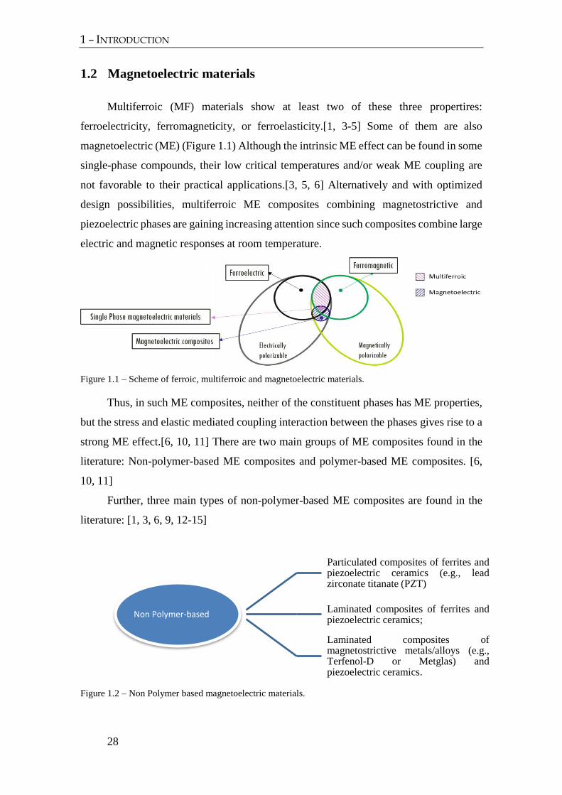
Multiferroic (MF) materials show at least two of these three propertires:
ferroelectricity, ferromagneticity, or ferroelasticity.[1, 3-5] Some of them are also
magnetoelectric (ME) (Figure 1.1) Although the intrinsic ME effect can be found in some
single-phase compounds, their low critical temperatures and/or weak ME coupling are
not favorable to their practical applications.[3, 5, 6] Alternatively and with optimized
design possibilities, multiferroic ME composites combining magnetostrictive and
piezoelectric phases are gaining increasing attention since such composites combine large
electric and magnetic responses at room temperature.
Figure 1.1 – Scheme of ferroic, multiferroic and magnetoelectric materials.
Thus, in such ME composites, neither of the constituent phases has ME properties,
but the stress and elastic mediated coupling interaction between the phases gives rise to a
strong ME effect.[6, 10, 11] There are two main groups of ME composites found in the
literature: Non-polymer-based ME composites and polymer-based ME composites. [6,
10, 11]
Further, three main types of non-polymer-based ME composites are found in the
literature: [1, 3, 6, 9, 12-15]
Figure 1.2 – Non Polymer based magnetoelectric materials.
Non Polymer-based
Particulated composites of ferrites andpiezoelectric ceramics (e.g., leadzirconate titanate (PZT)
Laminated composites of ferrites andpiezoelectric ceramics;
Laminated composites ofmagnetostrictive metals/alloys (e.g.,Terfenol-D or Metglas) andpiezoelectric ceramics.

1 – INTRODUCTION
29
Despite the ME coefficients obtained in ceramic-based ME composites being three orders
of magnitude higher than in single-phase materials, such composites may become fragile
and are limited by reactions at the interface regions, leading to high dielectric losses. They
have low electrical resistivity, are dense, brittle and can lead to fatigue and failure during
operation [1, 6].
The use of piezoelectric polymers, such as poly(vinylidene fluoride), PVDF, and its
copolymers can solve some of the problems found in ceramic composites since they are
flexible, show large electrical resistivity and small losses. Further, they can be easily
fabricated by large- and small-scale low- temperature processing methods into a variety
of forms.[6, 16, 17]
According to the literature, polymer-based ME composites also can be divided in
three main types [18]
Figure 1.3 - Polymer based magnetoelectric materials
Within those composites, laminated polymer-based ME materials are those with the
largest ME response, [19] being the highest value (21.46 V cm-1 Oe-1) reported by Fang
et al. for a three layer laminate comprising PVDF, Metglas and an epoxy resin. Such a
value was achieved at non-resonance frequencies by taking advantage of the flux
concentration effect, and is, so far, the highest response among this kind of materials at
non- resonance frequencies.[19] On the other hand, the highest ME value reported by Jin
et al. at the electromechanical resonance was 383 V cm-1 Oe-1 using cross-linked P(VDF-
TrFE)/Metglas 2605SA1 composite bonded with an epoxy resin. [20]
Polymer-based
(i) Nanocomposites
(ii) Polymer “as a binder”
(iii) Laminated composites

1 – INTRODUCTION
30
1.3 Applications
The ME coefficient values found in ME laminates as well as the broad range of
magnetic fields at which they respond, allow a large variety of applications in the areas
of magnetic resonance imaging, multiple-state memories, filters, sensors, actuators,
biomedical materials, energy harvesting systems among others. [17, 18] In some of these
applications, polymeric based ME materials, due to the polymers unique characteristics
can be taken to advantage.[18]
1.3.1 Sensors and actuators
The ME coefficients values found in polymer-based ME laminates as well as the
broad range of the magnetic fields at which they respond, allow a large range of
applications, in particular in the fields of magnetic sensors and actuators.[6, 21, 22]
Due to the limitations found in some of the conventional magnetic field sensors,
including low operational temperatures, cost and high operational power[6, 23], self-
powered polymer-based ME sensors are of increasing interest and applicability due to
their novel working principle [6, 24, 25].
1.3.2 Energy harvesting
The ever decreasing power requirement of electronic sensors and devices has
attracted attention to the energy harvesting technologies [26, 27].
Electronic devices steadily require lower power consumption and, due to this fact,
the possibility of feeding those devices by energy harvesting technologies increases.
This creates a larger interest in investigating materials that may have the necessary
characteristics for such harvesting.
Polymer-based ME composites have recently been evaluated for their use in energy-
harvesting applications [6] . Such devices harvest energy from sources already present in
the environment (thermal, mechanical and electromagnetic, among others). Currently one
of the most rapidly developing technologies is the harvesting of energy from vibrations,
with electromagnetic, electrostatic, magnetoelastic, or piezoelectric origin [28].
As described before, there has been significant advances in improving the
magnitude of ME coefficient of laminate composites, which will improve the ME energy
harvesting efficiency. ME materials based on piezoelectric polymers can be the next

1 – INTRODUCTION
31
generation of wearable energy-harvesting systems, due to their flexibility, versatility and
low cost.
1.3.3 Magnetostriction measurements on particles
Materials with large magnetostriction, λ, are extensively used in sensors, actuators,
micro-electromechanical systems and energy-harvesters, among others[29]. In this way,
the magnitude of the magnetostrictive strain of a magnetic material is of great concern
for the development and application on innovative technological devices.[30] Especially
in applications that involve nanoparticles, the magnetostriction should be determined in
their nanoscale in order to obtain more exact results.
The magnetostriction of a nanomaterial can be measured by direct or indirect methods.
Direct methods enable the magnetostrictive strain to be measured as a function of the
applied field, whereas indirect methods are suitable only for measuring the saturation
magnetostriction λsat, often in an agglomerated state [31]
Through the ME effect, it is possible to accurately determinate nanoparticle’s
magnetostriction at the nano-sized state, by using polymeric-composite materials.

1 – INTRODUCTION
32
1.4 Objectives
The general objective of this work is the optimization of ME polymer based
composites based on electroactive polymers for energy harvesting and sensor
applications.
Thus, the specific objectives are:
Develop composites and fabrication techniques for improving their ME response.
The studied materials will be based on the piezoelectric polymer PVDF and
several magnetostrictive materials such as Metglas and Vitrovac. The materials
will be characterized and the physical effects analyzed. Theoretical calculations
will be performed in order to optimize/design parameters and coupling conditions.
Develop a system for the characterization of the ME response.
Implement a working prototype able to demonstrate the basic principles of a ME
harvester. The harvester will be built and characterized. Further, the electronic
harvesting circuits will be optimized.
The developed materials will be also optimized, tested and characterized for
sensor and actuator applications.

1 – INTRODUCTION
33
1.5 Thesis structure
This thesis is divided into eight chapters to provide the logical evolution of the
developed work during this research. Five of the eight chapters are based on
published/submitted scientific papers. The thesis is divided in two main aspects of the
research work, Optimization (chapters 4 and 5) and Applications (chapters 6; 7 and 8).
The chapters 1 and 2 describe the general contextualization of the work. Also in
such chapters, the objectives of the study as well as the structure of the thesis are provided.
It is to notice that a specific state of the art is provided within each chapter.
Chapter 3 offers a description of the developed system for the characterization of
the ME response. In this chapter it is also provided a description of the experimental
procedures for each one of the different studies performed in this work, including
materials and preparation methods.
The chapters 4 and 5 report the optimization of the ME response of ME laminate
composites, including bonding layer, sizes and geometries.
The chapters 6, 7 and 8 report the main applications resulting from this research:
the characterization of ME laminates for sensor applications, the development of an
energy harvesting device with electronic optimization, and a new tool for the
determination of the magnetostrictive coefficient of nanoparticles via ME measurements,
respectively.
Finally, chapter 9 provides the general conclusions of the study as well as the future
work.

1 – INTRODUCTION
34
1.6 References
[1] J. Ma, J. Hu, Z. Li, and C.-W. Nan, "Recent Progress in Multiferroic
Magnetoelectric Composites: from Bulk to Thin Films," Advanced Materials, vol.
23, pp. 1062-1087, Mar 4 2011.
[2] G. Lawes and G. Srinivasan, "Introduction to magnetoelectric coupling and
multiferroic films," Journal of Physics D: Applied Physics, vol. 44, 2011.
[3] D. R. Patil, A. D. Sheikh, C. A. Watve, and B. K. Chougule, "Magnetoelectric
properties of ME particulate composites," Journal of Materials Science, vol. 43,
pp. 2708-2712, 2008.
[4] W. Prellier, M. P. Singh, and P. Murugavel, "The single-phase multiferroic
oxides: From bulk to thin film," Journal of Physics Condensed Matter, vol. 17,
pp. R803-R832, 2005.
[5] P. Martins, C. M. Costa, and S. Lanceros-Mendez, "Nucleation of Electroactive
β-phase Poly(vinilidene fluoride) with CoFe2O4 and NiFe2O4 Nanofillers: A
New Method for the Preparation of Multiferroic Nanocomposites," Appl. Phys. A
Mater. Sci. Process., vol. 103, pp. 233-237, 2011.
[6] P. Martins and S. Lanceros-Méndez, "Polymer-Based Magnetoelectric
Materials," Adv. Funct. Mater., vol. 23, pp. 3371-3385, 2013.
[7] C. W. Nan, "Magnetoelectric Effect in Composites of Piezoelectric and
Piezomagnetic Phases," Phys. Rev. B, vol. 50, pp. 6082-6088, 1994.
[8] M. Fiebig, "Revival of the Magnetoelectric Effect," J. Phys. D: Appl. Phys., vol.
38, pp. 123-152, 2005.
[9] C. W. Nan, M. I. Bichurin, S. Dong, D. Viehland, and G. Srinivasan, "Multiferroic
Magnetoelectric Composites: Historical Perspective, Status, and Future
Directions," J. Appl. Phys., vol. 103, pp. 1-35, 2008.
[10] M. Silva, S. Reis, C. S. Lehmann, P. Martins, S. Lanceros-Mendez, A. Lasheras,
et al., "Optimization of the Magnetoelectric Response of Poly(vinylidene
fluoride)/Epoxy/Vitrovac Laminates.," ACS Appl. Mater. Interfaces, vol. 5, pp.
10912-9, 2013.
[11] P. Martins, R. Gonçalves, S. Lanceros-Mendez, A. Lasheras, J. Gutiérrez, and J.
M. Barandiarán, "Effect of filler dispersion and dispersion method on the
piezoelectric and magnetoelectric response of CoFe2O4/P(VDF-TrFE)
nanocomposites," Applied Surface Science, vol. 313, pp. 215-219, 9/15/ 2014.
[12] J. Ryu, A. V. Carazo, K. Uchino, and H. E. Kim, "Piezoelectric and
magnetoelectric properties of lead zirconate titanate/Ni-ferrite particulate
composites," Journal of Electroceramics, vol. 7, pp. 17-24, 2001.
[13] R. A. Islam, Y. Ni, A. G. Khachaturyan, and S. Priya, "Giant magnetoelectric
effect in sintered multilayered composite structures," Journal of Applied Physics,
vol. 104, 2008.

1 – INTRODUCTION
35
[14] S. Dong, J. Zhai, F. Bai, J. Li, D. Viehland, and T. A. Lograsso, "Magnetostrictive
and magnetoelectric behavior of Fe-20 at. % Ga/Pb(Zr,Ti)O 3 laminates," Journal
of Applied Physics, vol. 97, 2005.
[15] Y. Jia, H. Luo, X. Zhao, and F. Wang, "Giant magnetoelectric response from a
piezoelectric/magnetostrictive laminated composite combined with a
piezoelectric transformer," Advanced Materials, vol. 20, pp. 4776-4779, 2008.
[16] K. J. Loh and D. Chang, "Zinc oxide nanoparticle-polymeric thin films for
dynamic strain sensing," Journal of Materials Science, vol. 46, pp. 228-237, 2011.
[17] J. F. Scott, "Applications of magnetoelectrics," Journal of Materials Chemistry,
vol. 22, pp. 4567-4574, 2012 2012.
[18] P. Martins, A. C. Lopes, and S. Lanceros-Mendez, "Electroactive Phases of
Poly(vinylidene fluoride): Determination, Processing and Applications," Prog.
Polym. Sci., vol. 39, pp. 683-706, 2013.
[19] Z. Fang, S. G. Lu, F. Li, S. Datta, Q. M. Zhang, and M. El Tahchi, "Enhancing
the Magnetoelectric Response of Metglas/Polyvinylidene Fluoride Laminates By
Exploiting the Flux Concentration Effect," Appl. Phys. Lett. , vol. 95, pp. 1-3,
2009.
[20] J. Jin, S. G. Lu, C. Chanthad, Q. Zhang, M. A. Haque, and Q. Wang, "Multiferroic
polymer composites with greatly enhanced magnetoelectric effect under a low
magnetic bias," Advanced Materials, vol. 23, pp. 3853-3858, 2011.
[21] S. Ju, S. H. Chae, Y. Choi, S. Lee, H. W. Lee, and C. H. Ji, "A low frequency
vibration energy harvester using magnetoelectric laminate composite," Smart
Materials and Structures, vol. 22, 2013.
[22] M. Alnassar, A. Alfadhel, Y. P. Ivanov, and J. Kosel, "Magnetoelectric polymer
nanocomposite for flexible electronics," Journal of Applied Physics, vol. 117,
2015.
[23] J. Lenz and A. S. Edelstein, "Magnetic sensors and their applications," IEEE
Sensors Journal, vol. 6, pp. 631-649, 2006.
[24] Y. Zhao and C. Lu, "Note: Self-biased magnetic field sensor using end-bonding
magnetoelectric heterostructure," Review of Scientific Instruments, vol. 86, p.
036101, 2015.
[25] H. Zhang, C. Lu, C. Xu, Y. Xiao, J. Gui, C. Lin, et al., "Improved magnetoelectric
effect in magnetostrictive/piezoelectric composite with flux concentration effect
for sensitive magnetic sensor," AIP Advances, vol. 5, p. 047114, 2015.
[26] R. J. M. Vullers, R. van Schaijk, I. Doms, C. Van Hoof, and R. Mertens,
"Micropower energy harvesting," Solid-State Electronics, vol. 53, pp. 684-693,
2009.
[27] H. S. Kim, J. H. Kim, and J. Kim, "A review of piezoelectric energy harvesting
based on vibration," International Journal of Precision Engineering and
Manufacturing, vol. 12, pp. 1129-1141, 2011.

1 – INTRODUCTION
36
[28] J. W. Matiko, N. J. Grabham, S. P. Beeby, and M. J. Tudor, "Review of the
application of energy harvesting in buildings," Measurement Science and
Technology, vol. 25, 2014.
[29] E. Lage, C. Kirchhof, V. Hrkac, L. Kienle, R. Jahns, R. Knöchel, et al., "Exchange
biasing of magnetoelectric composites," Nat Mater, vol. 11, pp. 523-529, 06//print
2012.
[30] D. Fritsch and C. Ederer, "First-principles calculation of magnetoelastic
coefficients and magnetostriction in the spinel ferrites CoFe 2O 4 and NiFe 2O
4," Phys. Rev. B, vol. 86, p. 014406 2012.
[31] P. Martins, A. Lasheras, J. Gutierrez, J. M. Barandiaran, I. Orue, and S. Lanceros-
Mendez, "Optimizing piezoelectric and magnetoelectric responses on
CoFe2O4/P(VDF-TrFE) nanocomposites," J. Appl. Phys. D, vol. 44, p. 495303,
2011.


2 Materials and methods This chapter provides a description of the materials used in this investigation, as well
as the experimental details on sample preparation. The development of the ME
measurement system is also described.

2– MATERIALS AND METHODS
39
2.1 Development of a magnetoelectric measurement system.
Due to the particularity of ME measurements, it was necessary to design and develop
a system that would allow the reliable and reproducible ME characterization of the
samples.
The developed system generates a controlled magnetic field that induces the
magnetostrictive element to change dimensions, when this variation occurs, the coupled
piezoelectric element also change its dimensions and generates a voltage. The voltage
generated by the samples is then analyzed.
In the following, the main components of the developed set-up are described and
explained.
2.1.1 Structure, dimensions and operating limits
The ME measurement system are constituted by a two pairs of Helmholtz coils,
which generate the magnetic field, these coils are connected to a DC and AC current
supply. The sample holder ensures the central position of the sample relatively to the
coils, and links the output signal to the Lock in Amplifier.
Figure 2.1 – Schematic representation of the ME measurement system.
The ME measurements are carried out by generating two magnetic fields, one AC and
one DC, that are applied to the sample. Thus, the constructed structure is composed by

2 – MATERIALS AND METHODS
40
two pairs of Helmholtz coils, being a couple responsible for creating the DC magnetic
field and the other for the AC magnetic field.
Figure 2.2 – Schematic design of the ME apparatus, constituted by two pairs of Helmholtz coils and a
sample holder.
Each pair of coils is connected to two distinct current sources, an AC and a DC. Thus,
AC and DC magnetic fields will be generated. The DC coils create magnetic fields in the
range 0-22 Oe while the AC coils can generate magnetic fields up to 1.5 Oe with
frequencies ranging from 1 mHz to 100 kHz.
The system was designed in the Autodesk Inventor software, which allowed the
simulation of the form and dimensions of the system, including the dimensions of the
Helmholtz coils, the size of the samples and the size of the sample holder in order to
ensure that the samples were always placed at the center of the coils.
The sample holder 10x10 mm, built in nylon, was added to the structure to ensure
signal optimization. The sample holder can be removed from the structure allowing to
attach the ME samples safer and to achieve a more simple placement of the ME materials
for testing. In order to carry out anisotropy tests on composites with different typologies,
the sample holder is also allowed to vary the angle between the length of the sample and
the direction of the applied magnetic fields.

2– MATERIALS AND METHODS
41
2.1.2 Helmholtz coils characterization
The concept of Helmholtz coils, developed by the German physicist Hermann von
Helmholtz for over a century, is used to perform compatibility and susceptibility testing
in electronic devices, magnetic fields measurements, biomagnetic applications and
cancellation of the Earth's magnetic field. To create a pair of Helmholtz coils it is required
two coils with the same diameter, composed by one or several windings.
In the case of having several windings, these should be wound in the same direction,
so that the electric signal can flow in the same direction in both coils, thus ensuring that
magnetic fields are all add up.
The distance between the coils must be equal to their radius.[1, 2]
The magnetic field produced by the coils can be static or time-varying, it is
perpendicular to the plane of the coils and more uniform in the center. The direction of
the magnetic field is determined by the direction of the current and can be easily
determined by the right hand rule. [3]
The value of the intensity of the magnetic field generated by the Helmholtz coils is
determined by factors such as the current value, coil dimensions and optimal distance
between them and number of spires.[1]
Figure 2.3 – Schematic representation and dimensions for construction of a pair of Helmholtz coils.
In order to predict the electrical and magnetic behavior of Helmholtz coils, and taking
into account the magnetism law of Biot-Savart to determine the magnetic field, it is

2 – MATERIALS AND METHODS
42
possible to describe the magnetic field at any point P, in the direction of the x-axis,
generated by a coil with an electric current I through the equation [4]:
𝐵 =
1
2
𝜇0𝑅𝑏2
(𝑅𝑏2 + 𝑥2)3 2⁄
𝐼 (4)
Were, 𝜇0 = 4𝜋 × 10−7𝑇 ∙ 𝑚/𝐴 it is the magnetic permeability in vacuum.
Considering now the magnetic field produced at the center of a coil pair, and that each
coil is formed by (N) turns separated by a distance (Rb), the two coils have (N) turns each,
multiplying the above equation by (2N) and substituting (x) to a point at the center of the
coils (x = Rb / 2) it is obtained the following [4, 5] equation:
𝐵 = (4
5)
32 𝜇0𝑁
𝑅𝑏𝐼 (5)
Through an analyses of the equation, it can be observed that the magnitude of the
magnetic field is proportional to (N) and (I) and inversely proportional to (Rb).
Measurements of the ME effect for magnetostrictive alloys used in this work (Vitrovac
and Metglas) do not require high intensity DC magnetic fields (<20 Oe).
From equation 5 it is possible to calculate the coils dimensions to the desired values
of magnetic field. The AC coils were constructed with a radius of 3 cm and 50 turns and
DC coils with a radius of 10 cm and 240 turns. During assembly, the coils were connected
in order to ensure that the current flows in the same direction in both coils. Each coil set
is connected in series to ensure that current in each coil pair has the same amplitude.
In detail, the magnetic field generated by the Helmholtz coils at a distance (d) from
the center of the coils can be obtained from equation 6.
𝐵 =𝜐0𝑁𝐼
2𝑅(1/ ((
𝑑
𝑅)2
+𝑑
𝑅+5
4)
32
+ 1/((𝑑
𝑅)2
+𝑑
𝑅+5
4)
32
) (6)
2.1.3 Current sources
Since the ME characterization of samples demands DC and AC magnetic fields, a
Keithley 2400 current source was selected to supply the DC coils and a Keithley 6221
current source for the AC coils. The first allows a maximum current of 10 A and the
second a maximum current of 100 mA with frequencies ranging from 1 mHz to 100 kHz.

2– MATERIALS AND METHODS
43
2.1.4 Lock-in Amplifier
For the ME characterization of the composites, as mentioned before, it is needed to
apply magnetic fields to the sample and to detect the output voltage signal at the terminals
of the ME composite. Due to the small amplitude of the output signal and to the existence
of electromagnetic noise, it a lock-in amplifier was used to amplify the signal and separate
the output signal from the noise.
The lock-in amplifier (Standford Research SR844) uses a technique called phase-
sensitive detection to separate the signal component in a specified phase and frequency.
A lock-in amplifier can be viewed as a filter with a very low bandwidth and tuned to the
signal frequency that is being measured, thus eliminating part of the noise.
Figure 2.4 - ME measurment system
2.2 Magnetoelectric measurements
Samples were characterized in a ME system composed by two Helmholtz coils
(Figure 2.1), one generating the DC magnetic field (HDC) in the range 0 to 20 Oe, and
another generating the AC magnetic field (HAC) in the range 0 to 0.2 Oe.
In order to determine the resonance frequency of the composite, the HDC and HAC
values were maintained constant (4.75 Oe and 0.1 Oe respectively) and the frequency was

2 – MATERIALS AND METHODS
44
changed from 20 kHz to 100 kHz. The DC magnetic field sensor characterization was
performed by keeping the HAC and frequency values constant (0.1 Oe and 48 kHz,
respectively). On the other hand, AC magnetic field sensor characterization was carried
out by keeping the HDC and frequency values constant (4.75 Oe and 48 kHz, respectively).
The voltage induced ( V ) in the piezoelectric layer was measured with a lock-in-
amplifier.
The ME response of the laminates was determined as:
AC
MEH
V
tdH
dE
1 (7)
where ACH is the applied AC magnetic field amplitude, V is the induced
magnetoelectric voltage and t is the thickness of the piezoelectric polymer.

2– MATERIALS AND METHODS
45
2.3 Sample preparation
2.3.1 Optimization of the magnetoelectric response of poly(vinylidene
fluoride)/epoxy/Vitrovac laminates
The following sample preparation procedure applies to the samples investigated in
Chapter 3.Commercial poly(vinylidene fluoride), PVDF, with thickness of 28, 52 and 110
µm with Cu-Ni electrodes deposited on both sides was purchased from Measurement
Specialties, USA, and used as the piezoelectric phase. All PVDF samples were cut into
rectangular shapes with 50 mm x 10 mm size.
Vitrovac 4040® (Fe39Ni39Mo4Si6B12), 30 mm x 6 mm x 25 μm magnetostrictive
ribbons were used as magnetostrictive components. With a magnetostrictive coefficient
λ11 of 8ppm. [6]
To study the effect of each epoxy on the ME response, laminated composites were
prepared by gluing the piezoelectric layer to the magnetostrictive layer with three
different epoxy resins, chosen due to their distinct mechanical properties (Young
Modulus given in the brackets):
ITW Devcon 5 Minute® Epoxy (7×10⁸ Pa),
Strain Gage Adhesive M-Bond 600 - Vishay Precision Group (2.7×10⁸ Pa)
Stycast 2850 FT blue (9×10⁹ Pa).
The Young Modulus of the epoxy resins was determined from the initial slope of
strain–stress curves measured using a Shimadzu AG-IS universal testing machine in
tensile mode, with a 2 mm min−1 loading rate.
Temperature dependent magnetoelectric induced voltage between room
temperature and 85 ºC was performed by introducing the whole experimental set-up
(sample, exciting, detecting and bias coils) inside a climatic chamber. Each sample was
tested at conditions of resonant frequency and optimized DC field, in order to obtain the
maximum ME response.

2 – MATERIALS AND METHODS
46
2.3.2 Size effects on the magnetoelectric response on PVDF/Vitrovac 4040
laminate composites
The following sample preparation procedure applies to the samples investigated in
Chapter 4.
Magnetostrictive samples from Vitrovac (Fe39Ni39Mo4Si6B12) 4040 (25 µm thick)
were cut into rectangular shapes using a clean and sharp ceramic scalpel. The rectangular
samples of Vitrovac 4040 exhibit a magnetostrictive coefficient λ11 of 8ppm.[6]
Poled β-PVDF films 28μm thick with Cu−Ni electrodes deposited on both sides
were purchased from Measurement Specialties, USA, and used as provided (d33 = −33
pC.N-1 and d31 =23 pC.N-1)[7]. All piezoelectric samples were cut into rectangular
shapes using a clean and sharp scalpel. The PVDF piezoelectric response (d33) was
verified with a wide range d33-meter (model 8000, APC Int. Ltd.) to ensure that the cutting
process had no effect on the piezoelectric response of the polymer.
To study the effect of the materials size, structure and geometry on the ME
response, various samples were produced as represented Figure 2.5.
Figure 2.5 - Top view of the Vitrovac/PVDF by-layer composites produced in this study (A-F). Front
view of the three-layer composites produced in this study (G-H).
In this way, in samples A-C the longitudinal size aspect ratio (LAR) between the PVDF
and the Vitrovac layers was changed between 1.1 and 4.3, in the samples A, D-F the
transversal size aspect ratio (TAR) between the PVDF and the Vitrovac layers was
changed between 2.0 and 4.0. Samples A-F allowed also to vary the relation between 2.2
and 8.6.

2– MATERIALS AND METHODS
47
)(
M
P
Vitrovac
PVDF
A
A
Area
Area (8)
Since the previous study demonstrated the extreme importance of the bonding layer
in the ME response of ME laminates [8], special care was taken in the bonding process
with the M-Bond epoxy in order to ensure a reproducible bonding and that the inner
structure of the interface is the same in all the samples. In this way, it is guaranteed that
all the differences in the ME response of the samples is due to the distinct configurations
and phase sizes and not a result of heterogeneities induded in the bonding process.
2.3.3 Characterization of Metglas/ Poly(vinylidene fluoride)/ Metglas
magnetoelectric laminates for AC/DC magnetic sensor applications
The following sample preparation procedure applies to the samples investigated in
Chapter 5. Polymer-based ME laminates were produced by gluing two equal amorphous
magnetostrictive ribbons of Metglas with a Devcon 5 minute epoxy (0.7 GPa Young
Modulus) to both sides of a commercial poled β-PVDF film (Measurement Specialties,
USA) in a (magnetostrictive-piezoelectric-magnetostrictive) MPM configuration,
following the optimized conditions presented in subchapter 2.1 [8-10]
The magnetostrictive ribbons (30 mm x 2 mm x 25 μm) were magnetized along
the longitudinal direction (magnetostrictive coefficient λ11=25 ppm) and the piezoelectric
layer (30 mm x 3 mm x 52 µm) was poled along the thickness direction (piezoelectric
coefficient d33 = −33 pC.N-1).
The voltage induced in the PVDF layer was measured with a lock-in-amplifier
(Standford Research SR844).as described in subchapter 2.2
Figure 2.6 - Detail of the ME laminated sample.

2 – MATERIALS AND METHODS
48
2.3.4 Development of an energy harvesting system with optimized circuit design.
The following sample preparation procedure applies to the samples investigated in
Chapter 6. For the ME characterization of the composites, the laminates were placed at
the centre of Helmholtz coils (Figure 2.7a). The external coils generated the DC magnetic
field (HDC 0-20 Oe) and the internal ones generated the AC magnetic field (HAC 0-0.4
Oe). Both magnetic fields were parallel and superimposed to each other.
Figure 2.7 - . a) Detail of the ME measurement set-up; b) Home-made ME sample holder; c) Schematic
representation of the ME composite produced with one piezoelectric layer and two magnetostrictive layers
bonded together with an epoxy resin (MPM configuration).
A home-made sample holder (Figure 2.7b) was used for the measurement of the
ME response of the laminates (Figure 2.7c) fabricated by using two equal amorphous
magnetostrictive ribbons of Metglas (30 mm × 5mm × 0.020 mm) magnetized along the
longitudinal direction (magnetostrictive coefficient λ11=30 ppm) bonded with a Devcon
5 minute epoxy (0.7 GPa Young Modulus) to both sides of a piezoelectric layer (30 mm
x 5 mm x 52 µm) poled along the thickness direction (piezoelectric coefficient d33 = −33
pC.N-1) and purchased from Measurement Specialties, USA. A detailed description of the
fabrication process is given in chapter 2.1[9]. The ME voltage generated by the composite
was then harvested by the collecting circuits.
.

2– MATERIALS AND METHODS
49
2.4 References
[1] C. F. de Melo, R. L. Araújo, L. M. Ardjomand, N. S. Ramos Quoirin, M. Ikeda,
and A. A. Costa, "Calibration of low frequency magnetic field meters using a
Helmholtz coil," Measurement, vol. 42, pp. 1330-1334, 11// 2009.
[2] J. H. Parry, "Helmholtz Coils and Coil Design," in Developments in Solid Earth
Geophysics. vol. Volume 3, K. M. C. D.W. Collinson and R. S.K, Eds., ed:
Elsevier, 2013, pp. 551-567.
[3] A. Yousaf, F. A. Khan, and L. M. Reindl, "Passive Wireless Sensing of Micro coil
parameters in fluidic environments," Sensors and Actuators A: Physical, vol. 186,
pp. 69-79, 10// 2012.
[4] M. A. Gijs, F. d. r. Lacharme, and U. Lehmann, "Microfluidic applications of
magnetic particles for biological analysis and catalysis," Chemical reviews, vol.
110, pp. 1518-1563, 2009.
[5] R. P. R. Caldeira, "Controlling superparamagnetic particles with dynamic
magnetic fields generated by a Helmholtz-coil system," 2010.
[6] J. Gutiérrez, A. Lasheras, J. M. Barandiarán, J. L. Vilas, A. Maceiras, and L. M.
León, "Improving the performance of high temperature piezopolymers for
magnetoelectric applications," in Key Engineering Materials vol. 543, ed, 2013,
pp. 439-442.
[7] P. Martins, A. C. Lopes, and S. Lanceros-Mendez, "Electroactive Phases of
Poly(vinylidene fluoride): Determination, Processing and Applications," Prog.
Polym. Sci., vol. 39, pp. 683-706, 2013.
[8] M. Silva, S. Reis, C. S. Lehmann, P. Martins, S. Lanceros-Mendez, A. Lasheras,
et al., "Optimization of the Magnetoelectric Response of Poly(vinylidene
fluoride)/Epoxy/Vitrovac Laminates.," ACS Appl. Mater. Interfaces, vol. 5, pp.
10912-9, 2013.
[9] A. Lasheras, J. Gutiérrez, S. Reis, D. Sousa, M. Silva, P. Martins, et al., "Energy
harvesting device based on a metallic glass/PVDF magnetoelectric laminated
composite," Smart Materials and Structures, vol. 24, 2015.
[10] M. P. Silva, P. Martins, A. Lasheras, J. Gutiérrez, J. M. Barandiarán, and S.
Lanceros-Mendez, "Size effects on the magnetoelectric response on
PVDF/Vitrovac 4040 laminate composites," Journal of Magnetism and Magnetic
Materials, vol. 377, pp. 29-33, 2015.


3 – BONDING AND THICKNESS OPTIMIZATION
3 Bonding and thickness optimization This chapter is based on the following publication:
Silva M, Reis S, Lehmann C S, Martins P, Lanceros-Mendez S, Lasheras A, Gutiérrez J
and Barandiarán J M 2013 Optimization of the Magnetoelectric Response of
Poly(vinylidene fluoride)/Epoxy/Vitrovac Laminates. ACS Appl. Mater. Interfaces 5
10912–9
.

3 – BONDING AND THICKNESS OPTIMIZATION
52
3.1 Introduction
Magnetoelectric (ME) materials are being increasingly investigated [1] due to their
potential applications as sensors, actuators, energy harvesting devices, memories,
transformers, filters, resonators and phase shifters, among others [1-4].
The main characteristic of ME materials is the variation of the electrical polarization
(P) in the presence of an applied magnetic field (H);
HP (9)
and the variation of the induced magnetization (M) in the presence of an applied
electrical field (E):
EM (10)
Where α is the E coupling coefficient [3, 5-7] In this way, through the ME effect it
can be achieved the cross-correlation between the magnetic and the electric orders of
matter.
In multiferroic (MF) single-phase materials this effect is intrinsic and attributed to
the coupling of magnetic moments and electric dipoles [3, 5, 6]. Nevertheless, single-
phase ME materials, so far, exhibit low Curie temperatures and show weak ME coupling
at room temperature, hindering in this way their incorporation in technological
applications [7, 8].
In multiple-phase ME materials this effect is extrinsic, emerging in an indirect form,
through an elastic mediated coupling between a piezoelectric phase and a
magnetostrictive phase [2, 3, 9].
Three main types of non-polymer based ME composites are found in the literature
[2, 3]: i) particulate composites of ferrites and piezoelectric ceramics (e.g. lead zirconate
titanate (PZT)) [7, 10-12]; ii) laminate composites of ferrites and piezoelectric ceramics
[13-15] and iii) laminate composites of magnetic metals/alloys (e.g. Terfenol-D or
Metglas) and piezoelectric ceramics [16-19]. The above mentioned composites are thus
based on piezoelectric ceramics, being therefore dense and brittle and can lead to fatigue
and failure during operation. Moreover those materials have low electrical resistivity and
high dielectric losses which can hinder specific applications [20, 21]. The use of
piezoelectric polymers, such as poly(vinylidene fluoride), PVDF, and its copolymers can
solve some of the problems, found in ceramic composites, since they are flexible, show

3 – BONDING AND THICKNESS OPTIMIZATION
53
large electrical resistivity, small losses and can be easily fabricated by large and small
scale low-temperature processing methods into a variety of forms [21-23].
Regarding polymer-based ME materials, three main types of composites can be
found in the literature: i) nanocomposites, ii) polymer “as a binder”, and iii) laminated
composites [4]. Laminated polymer-based ME materials are those with the highest ME
response. In particular Fang et al [24] reported a magnetoelectric voltage coefficient of
21.46 V.cm-1·Oe-1 for a laminate comprising PVDF, Metglas 2605SA1 and Devcon
epoxy. Such value was achieved at non-resonance frequencies by taking advantage of the
flux concentration effect and is, so far, the highest response among this kind of materials
at non-resonance frequencies. At the longitudinal electromechanical resonance, Jin et al
[25] reported a magnetoelectric voltage coefficient of 383 V.cm-1·Oe-1 on cross-linked
P(VDF-TrFE)/ Metglas 2605SA1 bonded with an epoxy resin, the highest value reported
up to date.
Despite those high values of ME response on polymer based ME laminates, proper
description, characterization and optimization of both piezoelectric and magnetostrictive
phases, the optimization of the element responsible for the coupling between the phases
(usually an epoxy) remains poorly studied [26, 27].
Trying to solve this limitation, in this work, PVDF was bonded to Vitrovac with
three epoxys with different elastic modulus in order to study their effect on the ME
response.
Vitrovac 4040 was used as magnetostrictive component not for its magnetostriction
value (λ=8 ppm), actually modest, but for its high piezomagnetic coefficient (1,3 ppm/Oe)
at low magnetic fields (≈15 Oe), and low cost[28]. PVDF was chosen as piezoelectric
component since it exhibits the highest piezoelectric response among polymers [23, 29].
In order to theoretically evaluate the experimental results, a Finite Element Method
(FEM) based simulation was also performed. Up to date, a wide amount of theoretical
approaches have been used to determine the ME response of
piezoelectric/magnetoestrictive composites, namely the Green’s function technique [30-
32], the finite element method [27, 33], the constitutive equations [34] and the effective
medium approximation [35]. Nevertheless, considering that both magnetostrictive and
piezoelectric behaviors are anisotropic, thus implying that the product effect must be
anisotropic and taking into account that in the ME structure reported in this work both
layers are separated by an epoxy bonding layer that incorporates specific mechanical

3 – BONDING AND THICKNESS OPTIMIZATION
54
coupling factors into the final ME response, the approach that best fits the evaluation of
the macroscopic experimental response is the FEM.
In this way, the ME response of the ME structure was studied as a function of the
PVDF thickness and the epoxy properties and the results were theoretically evaluated
with final goal to optimize such materials for applications in innovative technological
applications such as magnetic sensors (Figure 3.1).
Figure 3.1. Schematic representation of the Vitrovac/Epoxy/PVDF composite (a) and its ME
response (c) after optimization (b) that pave the way for its incorporation into technological applications
such as magnetic sensors (d).

3 – BONDING AND THICKNESS OPTIMIZATION
55
3.1.1 Theoretical analysis by Finite Element Method
Assuming the linear range of magnetostriction, the electro-mechanical coupling of the
3-layer (piezoelectric+epoxy+magnetostrictive) ME structure –Figure 3.1a- was modeled
by Finite Element Method (FEM) in order to obtain the theoretical ME response. A 2D
approximation has been considered by establishing the ME response to be constant along
the width of the structure. The model additionally considers the ME structure as
composed by three flexible films -magnetostrictive layer of Vitrovac, epoxy layer and
piezoelectric layer of PVDF- properly glued to each other with an appropriate coupling
between the structural and electrical fields. This coupling is fulfilled by the continuity
equations on the stationary case, given by:
VD (Gauss Law, t=0) (11)
Vf (Cauchy Momentum Equation, t=0) (12)
Here “” represents the divergence, D the electrical displacement field, ρv, the free
electric charge density, σ, the stress tensor and fv the force per unit volume.
The constitutive equations for the fully coupled piezoelectric material consist on the
direct and indirect piezoelectric effects and are given by [36]
T = cES − eTE (13)
DA = eS + εSE (14)
where T is the mechanical stress matrix, S the mechanical strain matrix, E the electric
field vector and DA the electric charge vector per unit area.
A coupling coefficient (k) was included to represent the coupling between the epoxy
and both Vitrovac and PVDF layers. Such coefficient was set to be between 0 (not
coupled) and 1 (ideal coupling).
The input parameter for the calculations will be S=λ(H), which is the magnetically
induced magnetostrictive strain in the Vitrovac 4040 constituent.
The material properties of the poled piezoelectric PVDF polymer are described by the
mechanical stiffness matrix at constant electric field cE, the permittivity matrix under
constant strain εS, and the piezoelectric stress matrix eS. These properties are shown in
Table 1.

3 – BONDING AND THICKNESS OPTIMIZATION
56
Table 3.1 - Material properties of the piezoelectric PVDF polymer [37, 38].
Property Value
Density (ρ) 1780 kg/m3
Elasticity matrix,
cE (Pa)
(xx, yy, zz, yz, xz, xy)
2.74 × 1009, 5.21 × 1009, 4.78 × 1009,0,0,0,
5.21 × 1009, 2.36 × 1009, 5.21 × 1009,0,0,0,
4.78 × 1009, 5.21 × 1009, 2.12 × 1009,0,0,0,
0, 0, 0, 2.74 × 1009, 0, 0,
0, 0, 0, 0, 2.74 × 1009, 0,
0, 0, 0, 0, 0, 2.74 × 1009
Compliance matrix,
cE−1 (Pa−1)
(xx, yy, zz, yz, xz, xy)
3.65 × 10⁻¹⁰, −1.92 × 10⁻¹⁰, 4.24 × 10⁻¹⁰, −2.09 × 10⁻¹⁰, −1.92 ×
10−10, 4.72 × 10⁻¹⁰, 0, 0, 0, 3.65 × 10⁻¹⁰, 0, 0, 0, 0, 3.65 × 10⁻¹⁰, 0, 0,
0, 0, 0, 3.65 × 10⁻¹⁰
Coupling matrix,
e (C·m−1)
(xx, yy, zz, yz, xz, xy)
0, 0, -4.761, 0, 0, -33.33,
0, 0, 3.703, 0, 1.703, 0,
1.703, 0, 0, 0, 0, 0
Relative permittivity,
(εS)
13, 0, 0,
0, 13, 0,
0, 0, 13
The three layers forming the ME structure are represented in Figure 3.1a together
with the polarization and magnetization directions. The size of the ME structure was set
to be 30 mm x 10 mm. The thickness of the magnetostrictive layer was fixed to 25 μm
and its mechanical properties are shown in Table 2. The experimental cases of
piezoelectric layer thickness of 28 μm, 52 μm and 110 μm are studied taken a constant
epoxy thickness of 12 μm (determined by scanning electron microscopy (SEM)
microscopy).

3 – BONDING AND THICKNESS OPTIMIZATION
57
Table 3.2 - Mechanical properties of Vitrovac 4040.
Property Value Unit
Density (ρ) 7900 kg/m3
Poisson´s Ratio (ν) 0.27 -
Young´s Modulus (Y) 1500 MPa
The theoretical evaluation consisted in applying a deformation on the two lateral
ends of the magnetostrictive layer consistent with the magnetostrictive response of the
material [39, 40] and evaluating the electrical potential obtained across the piezoelectric
layer. The applied deformation of the magnetostrictive Vitrovac 4040 will be obtained
from the Magnetic Field-Magnetostriction curve of the material [39]. It will be chosen in
all cases as the strain corresponding to the maximum deformation experienced by the
magnetostrictive layer. Structurally, when the three layers are perfectly bonded, the
deformation on the magnetostrictive layer will produce a deformation on the other 2
layers, which will depend on their mechanical properties. The electrical ground was set
at the outer surface of the piezoelectric layer, locating also a compliant electrode between
the piezoelectric and the bonding layer. The ME structure is set to deform only along the
longitudinal direction.
The influence of the bonding layer Young Modulus on the ME performance of the
structure was thus simulated together with the ME response of the laminate with varying
piezoelectric and bonding layer thickness, in order to optimize the ME response of the
fabricated multilayer structures.

3 – BONDING AND THICKNESS OPTIMIZATION
58
3.2 Results and discussion
In this chapter Vitrovac was used as magnetostrictive layer, and PVDF as
piezoelectric layer. The bounding layer were composed by three different epoxy resins,
M-Bond, Stycast and Devcon. Sample preparation and specifications are described in
subchapter 2.3.1.
Figure 3.2 shows the ME response of laminate composites of 110 µm thick PVDF
films bonded with Devcon, M-Bond and Stycast to Vitrovac magnetostrictive substrates.
Figure 3.2 - a) Magnetoelectric response, α, at resonance obtained for the PVDF/epoxy/Vitrovac
composites for a 110 µm PVDF layer and different epoxy binders; b) Relation between α and the epoxy
Young Modulus. Images from the numerical simulation of the ME effect
The obtained results reveal the strong influence of the epoxy layer on the ME
response of the composite.
The highest ME response has been obtained for the M-Bond bonded composites,
the epoxy with the lowest Young modulus; on the contrary, the lowest response is
obtained for Stycast bonded composites, which is the epoxy with the highest Young
Modulus and lower k value used [26, 27, 41]. It is observed that with higher Young
Modulus the epoxy loses its ability to transmit the deformation from the magnetostrictive
layer to the piezoelectric layer due to the increased rigidity, leading to a decreasing in the
coupling factor from 0.6 to 0.07 , revealing so an interface detachment between the active
layers and the epoxy layer. Further, the highest ME response is obtained at the lowest
applied HDC filed by using M-Bond; in correspondence, Stycast shows the lowest ME
response at the highest applied HDC field. Devcon containing composites show an

3 – BONDING AND THICKNESS OPTIMIZATION
59
intermediate behavior. This relationship between the ME response and the Young
Modulus shows the relevance of the later parameter for the fabrication of devices and
indicates the best choice for ME performance optimization. These results are supported
by the simulations as the images obtained by FEM (Figure 3.2c, d and e) show a more
intense red and blue colors, indicating higher induced voltage values and so higher ME
response, for the M-Bond bonded laminates.
As the M-Bond bonded laminates show the highest ME response, this epoxy was
used in the study of the effect of the thickness of the PVDF layer on the ME response of
PVDF/M-Bond/Vitrovac laminates.
PVDF layers with 28, 52 and 110 µm were used and it was evaluated, both
experimentally and through theoretical FEM simulations, the effect of the piezoelectric
layer thicknesses on the ME response of the composites. Figure 3.3a shows the ME
coefficient as a function of the DC applied field and Figure 3.3b the comparison of
experimentally and theoretically obtained values of the ME coefficient for the different
piezoelectric layer thickness.
Figure 3.3 - a) Magnetoelectric coefficient, α, measured at the resonance frequency as a function of the DC
magnetic field for piezoelectric layer of different thickness and b) comparison between the experimental
and theoretical results. Images from the FEM simula
As previously reported, Figure 3.3 shows that the ME response of PVDF based ME
laminated composites increases with increasing thickness of PVDF layer [42].
Nevertheless, an increase of 300% in the thickness of PVDF (from 28µm to 110µm) has,
as a consequence, just an increase of 20% in the ME response (from 45 V.cm-1.Oe-1 to 53
V.cm-1.Oe-1).

3 – BONDING AND THICKNESS OPTIMIZATION
60
In the images obtained by the FEM simulations (Figure 3.3 c, d and e) it can be
observed that the intensity of the red and blue colors increases with increasing thickness
of PVDF. With increasing the PVDF layer thickness a larger number of dielectric
moments suffer variation under the applied stress, resulting in a higher ME response [41].
However it should be noted that it must exist a maximum value for the PVDF thickness
at which the ME response is maximized as a larger thicknesses will lead to
inhomogeneous deformations of the material, with more deformation at the boundary
layer with the binder and lower deformation at the down side, thus decreasing its ME
response [41], as shown in the simulation represented in Figure 3.4.
Figure 3.4 - Numerical simulation of a thick PVDF layer (750 µm) bonded to a Vitrovac layer with M-
Bond epoxy (12 µm).
Figure 3.4 shows that for a very thick layer of PVDF (750 µm) the deformation
generated by Vitrovac is only transmitted to a volume fraction of the PVDF layer close
to the epoxy layer, causing the observed decrease of the magnitude of the ME effect.
Another important parameter for practical applications is the thermal stability of the
device. Figure 3.5 shows the variation of the ME response with temperature in the
temperature range 20-85 oC for a PVDF 110µm/M-Bond/Vitrovac laminate. The
maximum temperature of 85 ºC was chosen as around that temperature, PVDF undergoes
the α-relaxation leading to strong shrinking of the material [43].

3 – BONDING AND THICKNESS OPTIMIZATION
61
20 30 40 50 60 70 80 90
0
20
40
60
(k=0.11)
(k=0.43)
(k=0.56)(k=0.60)
T(oC)
(V
/cm
.Oe
) Experimental
Theoretical
Figure 3.5 - Temperature dependence of the magnetoelectric coefficient, α, measured at the resonance
frequency for the composites PVDF (110µm)/M-Bond/Vitrovac.
As previously reported [28] the ME response of PVDF based materials decreases
with increasing temperature. This decrease is not mainly explained by the depoling effects
(related to increased molecular mobility with increasing temperature) which leads to a
decreased piezoelectric response, since it is reported just a decrease of 20% in the PVDF
piezoelectric coefficient when the temperature increases until 100ºC [44]. Figure 3.5
demonstrates a decrease of more than 80% in the ME response of the laminate which is
related with a decrease of the coupling, defined as k, between the epoxy and the active
layers of the laminate. The coupling factor k varies from 0.6 at room temperature to 0.11
at 80 oC, and reflects a weaker coupling between the layers due to a softening of the
materials leading to a smaller k. Results on Figure 3.2 suggest that softer materials possess
higher k value. In this way, the k values decrease revealed in Figure 3.5 should be related
with the temperature dependent deformations that lead to interface detachment (due to
the different thermal expansion coefficients of the material) and therefore reduced
transduction capability.
Despite the temperature effect on the ME response, the ME coupling coefficient
still remains at suitable values up to temperatures of 80 ºC, which allows widespread use
for sensor and actuator applications. In a similar way, it has been reported that PVDF still
retains stable piezoelectric response after temperature annealing at 140 ºC, with a value
of ~ -4 pC/N, which is still high for polymer systems [44], making this polymer an

3 – BONDING AND THICKNESS OPTIMIZATION
62
appropriate choice for the development of the flexible, low cost and easy shaping ME
materials with large potential for device fabrication [4].
Finally, the ME response of the laminates was theoretically optimized regarding the
epoxy properties (Young Modulus and thickness) and the thickness of the PVDF
piezoelectric layer (Figure 3.6).
Figure 3.6 - Theoretical ME response as a function of a) epoxy Young modulus; b) epoxy thickness and c)
PVDF layer thickness.
Figure 3.6a reveals that at the 106 Pa Young Modulus value occurs an abrupt change
in the epoxy behavior. For lower values the epoxy behaves as a rubber, stretching in the
vicinity of the magnetostrictive material and cringing in the vicinity of the PVDF layer.
For higher values of the Young Modulus, the epoxy loses its ability to transmit the
deformation from the magnetostrictive layer to the piezoelectric layer due to the increased
rigidity, having as a consequence a decrease in the ME response.
Increasing the epoxy thickness leads to an increase of the ME voltage coefficient
explained by a better coupling between the epoxy layer and the other two layers, as
represented on Figure 3.6b. From a certain value of epoxy thickness, the glue loses the
ability to transmit the deformation between the layers, the decrease being is explained by
the high distance between the layer in which the deformation occurs (Vitrovac) and the
layer on which the deformation has to be transmitted (PVDF), as a consequence part of
the deformation is damped along the thick epoxy layer. Thicker epoxy layers will also
limit the ME response due to low mechanical strength and contributes towards increasing
noise level and aging [45].
Figure 3.6c shows an increased ME as a response to the increase of the PVDF layer
thickness until it reaches the value of 700 µm.
As previously mentioned, increasing the PVDF layer thickness gives as a first
consequence that a larger number of dielectric moments will suffer variation under the
applied stress, resulting in a higher ME response [41], nevertheless above 700 µm thick
layers, inhomogeneous deformations of the material will be obtained, with larger
c
)
b
)
a
)
5 10 15
-500
-250
0
250
500
(
V.c
m-1.O
e-1)
10Epoxy Young Modulus (Pa)
PVDF 110 m
Epoxy 12 m
0 500 100080
100
120
PVDF 110 m
M-Bond epoxy
(V
.cm
-1.O
e-1)
Epoxy Thickness (m) 0 300 600 900
100
150
200
PVDF Thickness (m)
PVDF 110 m
M-Bond 12 m
(
V.c
m-1.O
e-1)

3 – BONDING AND THICKNESS OPTIMIZATION
63
deformations at the boundary layer with the binder and lower deformation far from that
layer, thus decreasing the ME response [41].
3.3 Conclusions
The effect of the bonding layer type and piezoelectric layer thickness on the ME
response of layered poly(vinylidene fluoride) (PVDF)/epoxy/Vitrovac composites is
reported. The materials have been experimentally and theoretically studied through
FEM model, including the magnetoelastic and piezoelectric laws. It is verified an
increase of the ME voltage coefficient from 45 V.cm-1.Oe-1 to 53 V.cm-1.Oe-1 with
increasing PVDF thickness from 28 µm to 110 µm and a reduction of the ME voltage
coefficient from 53 V.cm-1.Oe-1 to 6 V.cm-1.Oe-1 with increasing Young Modulus from
9.0×10⁹ Pa to 2.7×10⁸ Pa.
The k value, indicative of the quality of the bonding between the active layers and
the epoxy layer is the highest for the M-Bond laminates (0.60) and lowest for the Stycast
laminates (0.07). Stycast laminates exhibits an intermediate behaviour. Also regarding
the k values, it is found that it decreases with increasing temperatures due to interface
detachment and leading to reduced transduction.
Good agreement between the FEM model and the experimental results were
obtained for PVDF/epoxy/Vitrovac tri-layer composites allowing the model to be used
for optimizing the epoxy properties (Young modulus and thickness) and the thickness
of PVDF in order to obtain the highest ME coupling on the laminates.
The highest ME response of 53 V.cm-1.Oe-1 obtained for a PVDF (100µm
thick)/M-Bond epoxy/Vitrovac laminate as well as the possibility to optimize such value
taking into account the Young Modulus and thickness of the epoxy and the the PVDF
thickness, make this laminate an excellent candidate to be used in applications such as
sensors, actuators, energy harvesting devices and memories.

3 – BONDING AND THICKNESS OPTIMIZATION
64
3.4 References
[1] M. Fiebig, "Revival of the magnetoelectric effect," Journal of Physics D: Applied
Physics, vol. 38, pp. R123-R152, 2005.
[2] C. W. Nan, M. I. Bichurin, S. Dong, D. Viehland, and G. Srinivasan, "Multiferroic
magnetoelectric composites: Historical perspective, status, and future directions,"
Journal of Applied Physics, vol. 103, 2008.
[3] J. Ma, J. Hu, Z. Li, and C.-W. Nan, "Recent Progress in Multiferroic
Magnetoelectric Composites: from Bulk to Thin Films," Advanced Materials, vol.
23, pp. 1062-1087, Mar 4 2011.
[4] P. Martins and S. Lanceros-Méndez, "Polymer-Based Magnetoelectric
Materials," Advanced Functional Materials, pp. n/a-n/a, 2013.
[5] W. Prellier, M. P. Singh, and P. Murugavel, "The single-phase multiferroic
oxides: From bulk to thin film," Journal of Physics Condensed Matter, vol. 17,
pp. R803-R832, 2005.
[6] G. Lawes and G. Srinivasan, "Introduction to magnetoelectric coupling and
multiferroic films," Journal of Physics D: Applied Physics, vol. 44, 2011.
[7] D. R. Patil, A. D. Sheikh, C. A. Watve, and B. K. Chougule, "Magnetoelectric
properties of ME particulate composites," Journal of Materials Science, vol. 43,
pp. 2708-2712, 2008.
[8] P. Martins, C. M. Costa, and S. Lanceros-Mendez, "Nucleation of electroactive β-
phase poly(vinilidene fluoride) with CoFe2O4 and NiFe2O4 nanofillers: A new
method for the preparation of multiferroic nanocomposites," Applied Physics A:
Materials Science and Processing, vol. 103, pp. 233-237, 2011.
[9] S. Priya, R. Islam, S. Dong, and D. Viehland, "Recent advancements in
magnetoelectric particulate and laminate composites," Journal of
Electroceramics, vol. 19, pp. 147-164, 2007.
[10] J. Ryu, A. V. Carazo, K. Uchino, and H. E. Kim, "Piezoelectric and
magnetoelectric properties of lead zirconate titanate/Ni-ferrite particulate
composites," Journal of Electroceramics, vol. 7, pp. 17-24, 2001.
[11] J. Zhai, N. Cai, Z. Shi, Y. Lin, and C. W. Nan, "Magnetic-dielectric properties of
NiFe2O4/PZT particulate composites," Journal of Physics D: Applied Physics,
vol. 37, pp. 823-827, 2004.
[12] R. A. Islam and S. Priya, "Effect of piezoelectric grain size on magnetoelectric
coefficient of Pb(Zr0.52Ti0.48)O3-Ni0.8Zn 0.2Fe2O4 particulate composites,"
Journal of Materials Science, vol. 43, pp. 3560-3568, 2008.
[13] G. Srinivasan, E. T. Rasmussen, J. Gallegos, R. Srinivasan, Y. I. Bokhan, and V.
M. Laletin, "Magnetoelectric bilayer and multilayer structures of magnetostrictive

3 – BONDING AND THICKNESS OPTIMIZATION
65
and piezoelectric oxides," Physical Review B - Condensed Matter and Materials
Physics, vol. 64, pp. 2144081-2144086, 2001.
[14] G. Srinivasan, E. T. Rasmussen, and R. Hayes, "Magnetoelectric effects in ferrite-
lead zirconate titanate layered composites: The influence of zinc substitution in
ferrites," Physical Review B - Condensed Matter and Materials Physics, vol. 67,
pp. 144181-1441810, 2003.
[15] R. A. Islam, Y. Ni, A. G. Khachaturyan, and S. Priya, "Giant magnetoelectric
effect in sintered multilayered composite structures," Journal of Applied Physics,
vol. 104, 2008.
[16] J. Ryu, S. Priya, K. Uchino, and H. E. Kim, "Magnetoelectric effect in composites
of magnetostrictive and piezoelectric materials," Journal of Electroceramics, vol.
8, pp. 107-119, 2002.
[17] S. Dong, J. F. Li, and D. Viehland, "Characterization of magnetoelectric laminate
composites operated in longitudinal-transverse and transverse-transverse modes,"
Journal of Applied Physics, vol. 95, pp. 2625-2630, 2004.
[18] S. Dong, J. Zhai, F. Bai, J. Li, D. Viehland, and T. A. Lograsso, "Magnetostrictive
and magnetoelectric behavior of Fe-20 at. % Ga/Pb(Zr,Ti)O 3 laminates," Journal
of Applied Physics, vol. 97, 2005.
[19] Y. Jia, H. Luo, X. Zhao, and F. Wang, "Giant magnetoelectric response from a
piezoelectric/magnetostrictive laminated composite combined with a
piezoelectric transformer," Advanced Materials, vol. 20, pp. 4776-4779, 2008.
[20] S. Jiansirisomboon, K. Songsiri, A. Watcharapasorn, and T. Tunkasiri,
"Mechanical properties and crack growth behavior in poled ferroelectric PMN-
PZT ceramics," Current Applied Physics, vol. 6, pp. 299-302, 2006.
[21] K. J. Loh and D. Chang, "Zinc oxide nanoparticle-polymeric thin films for
dynamic strain sensing," Journal of Materials Science, vol. 46, pp. 228-237, 2011.
[22] J. F. Scott, "Applications of magnetoelectrics," Journal of Materials Chemistry,
vol. 22, pp. 4567-4574, 2012 2012.
[23] P. Martins, A. C. Lopes, and S. Lanceros-Mendez, "Electroactive phases of
poly(vinylidene fluoride): Determination, processing and applications," Progress
in Polymer Science.
[24] Z. Fang, S. G. Lu, F. Li, S. Datta, Q. M. Zhang, and M. El Tahchi, "Enhancing
the magnetoelectric response of Metglas/polyvinylidene fluoride laminates by
exploiting the flux concentration effect," Applied Physics Letters, vol. 95, 2009.
[25] J. Jin, S. G. Lu, C. Chanthad, Q. Zhang, M. A. Haque, and Q. Wang, "Multiferroic
polymer composites with greatly enhanced magnetoelectric effect under a low
magnetic bias," Advanced Materials, vol. 23, pp. 3853-3858, 2011.

3 – BONDING AND THICKNESS OPTIMIZATION
66
[26] C. W. Nan, G. Liu, and Y. Lin, "Influence of interfacial bonding on giant
magnetoelectric response of multiferroic laminated composites of Tb1-xDyxFe2
and PbZrxTi1-xO3," Applied Physics Letters, vol. 83, pp. 4366-4368, 2003.
[27] G. Liu, C. W. Nan, N. Cai, and Y. Lin, "Dependence of giant magnetoelectric
effect on interfacial bonding for multiferroic laminated composites of rare-earth-
iron alloys and lead-zirconate-tltanate," Journal of Applied Physics, vol. 95, pp.
2660-2664, 2004.
[28] J. Gutierrez, A. Lasheras, J. M. Barandiaran, J. L. Vilas, M. S. Sebastian, and L.
M. Leon, "Temperature Response of Magnetostrictive/Piezoelectric Polymer
Magnetoelectric Laminates," in Materials and Applications for Sensors and
Transducers. vol. 495, E. Hristoforou and D. S. Vlachos, Eds., ed, 2012, pp. 351-
354.
[29] P. Martins, A. Lasheras, J. Gutierrez, J. M. Barandiaran, I. Orue, and S. Lanceros-
Mendez, "Optimizing piezoelectric and magnetoelectric responses on CoFe 2O
4/P(VDF-TrFE) nanocomposites," Journal of Physics D: Applied Physics, vol.
44, 2011.
[30] C. W. Nan, "Magnetoelectric effect in composites of piezoelectric and
piezomagnetic phases," Physical Review B, vol. 50, pp. 6082-6088, 1994.
[31] N. Ce Wen, M. Li, and J. H. Huang, "Calculations of giant magnetoelectric effects
in ferroic composites of rare-earth-iron alloys and ferroelectric polymers,"
Physical Review B - Condensed Matter and Materials Physics, vol. 63, pp.
1444151-1444159, 2001.
[32] N. Cai, J. Zhai, C. W. Nan, Y. Lin, and Z. Shi, "Dielectric, ferroelectric, magnetic,
and magnetoelectric properties of multiferroic laminated composites," Physical
Review B - Condensed Matter and Materials Physics, vol. 68, pp. 2241031-
2241037, 2003.
[33] G. Liu, C. W. Nan, N. Cai, and Y. Lin, "Calculations of giant magnetoelectric
effect in multiferroic composites of rare-earth-iron alloys and PZT by finite
element method," International Journal of Solids and Structures, vol. 41, pp.
4423-4434, 2004.
[34] B. Bao and Y. Luo, "Theory of magnetoelectric effect in laminate composites
considering two-dimensional internal stresses and equivalent circuit," Journal of
Applied Physics, vol. 109, pp. 094503-5, 2011.
[35] S. Srinivas and J. Y. Li, "The effective magnetoelectric coefficients of
polycrystalline multiferroic composites," Acta Materialia, vol. 53, pp. 4135-4142,
2005.
[36] A. Preumont and F. Bossens, "Active tendon control of vibration of truss
structures: theory and experiments," Journal of Intelligent Material Systems and
Structures, vol. 11, pp. 91-99, 2000.
3 – BONDING AND THICKNESS OPTIMIZATION
67
[37] D. Esterly, "Manufacturing of Poly(vinylidene fluoride) and Evaluation of its
Mechanical Properties," Master of Science, Virginia Polytechnic Institute and
State University, Blacksburg, Virginia, 2002.
[38] M. Martins, V. Correia, J. M. Cabral, S. Lanceros-Mendez, and J. G. Rocha,
"Optimization of piezoelectric ultrasound emitter transducers for underwater
communications," Sensors and Actuators, A: Physical, vol. 184, pp. 141-148,
2012.
[39] A. Grunwald and A. G. Olabi, "Design of a magnetostrictive (MS) actuator,"
Sensors and Actuators, A: Physical, vol. 144, pp. 161-175, 2008.
[40] K. Fonteyn, A. Belahcen, R. Kouhia, P. Rasilo, and A. Arkkio, "FEM for directly
coupled magneto-mechanical phenomena in electrical machines," IEEE
Transactions on Magnetics, vol. 46, pp. 2923-2926, 2010.
[41] M. Li, D. Hasanyan, Y. Wang, J. Gao, J. Li, and D. Viehland, "Theoretical
modelling of magnetoelectric effects in multi-push-pull mode Metglas/piezo-fibre
laminates," Journal of Physics D-Applied Physics, vol. 45, Sep 5 2012.
[42] J. Carvell, R. Cheng, and Q. Yang, "Induced magneto-electric coupling at
ferroelectric/ferromagnetic interface," Journal of Applied Physics, vol. 113, pp.
17C715-3, 2013.
[43] V. Sencadas, S. Lanceros-Méndez, R. Sabater I Serra, A. Andrio Balado, and J.
L. Gómez Ribelles, "Relaxation dynamics of poly(vinylidene fluoride) studied by
dynamical mechanical measurements and dielectric spectroscopy," European
Physical Journal E, vol. 35, 2012.
[44] M. P. Silva, C. M. Costa, V. Sencadas, A. J. Paleo, and S. Lanceros-Méndez,
"Degradation of the dielectric and piezoelectric response of β-poly(vinylidene
fluoride) after temperature annealing," Journal of Polymer Research, vol. 18, pp.
1451-1457, 2011.
[45] Y. Yan, Y. Zhou, and S. Priya, "Giant self-biased magnetoelectric coupling in co-
fired textured layered composites," Applied Physics Letters, vol. 102, Feb 4 2013.

4 Size and geometry optimization This chapter is based on the following publication:
Silva M P, Martins P, Lasheras A, Gutiérrez J, Barandiarán J M and Lanceros-Mendez S
2014 Size effects on the magnetoelectric response on PVDF/Vitrovac 4040 laminate
composites J. Magn. Magn. Mater. 377 29–33

4 – SIZE AND GEOMETRY OPTIMIZATION
69
4.1 Introduction
Magnetoelectric materials (ME) are characterized by the variation of the electric
polarization (P) in the presence of an applied magnetic field (H) (equation 1),
∆𝑃 = 𝛼∆𝐻 (15)
where α is the ME coupling coefficient [1-4]. In single-phase materials this effect is
intrinsic and corresponds to the coupling between magnetic moments and electric dipoles
[1-3]. Low Curie temperatures and weak ME coupling at room temperature difficult their
introduction in technological applications [4-6].
Due to those limitations, the research interest began to focus in the ME effect of
multiple-phase materials, in which such effect is a result of the product of the
magnetostrictive effect (magnetic/mechanical) within the magnetostrictive phase and the
piezoelectric effect (mechanical/electrical) within the piezoelectric phase (equation 2).
B
E
magnetic
mechanical
mechanical
electriceffectMEH
(16)
where B and E are the piezomagnetic coefficient and piezoelectric
coefficients respectively. Thus, the ME effect in multiple-phase materials is extrinsic,
strongly depending on the microstructure and coupling interaction across the magnetic-
piezoelectric interfaces [6-8].
This ME-product property leads to output signals at room temperature that are many
orders of magnitude higher than the ones in single phase materials, being therefore very
attractive for innovative applications in areas such as such as brain activity sensors and
magnetic sensors (Figure 4.1), among others [1, 6, 7, 9].

4 – SIZE AND GEOMETRY OPTIMIZATION
70
Figure 4.1 - Possible applications of ME materials: Monitoring brain activity and magnetic sensors.
Additionally, the multiferroic composite approach offers a large potential for
technological optimization because of the degrees of freedom in sensor design, including
the choice of the piezoelectric and magnetostrictive materials, their deposition process
and/or binding and their three dimensional arrangement [10]. In the last decade, different
approaches for the development of ME-sensors have been reported, all of them based on
one of two fundamental type of piezoelectric materials: either are constituted by
piezoelectric ceramics or piezoelectric polymers [6], together with the magnetostrictive
element.
Piezoelectric ceramics have low electrical resistivity, high dielectric losses and
moreover are dense and brittle, which can lead to fatigue and failure.[6, 11, 12] In order
to improve and solve some problems related to ceramic composites, piezoelectric
polymers such as poly(vinylidene fluoride), PVDF, and its copolymers have been used
since they are flexible, show large electrical resistivity and low losses, and can be
processed in different shapes at low processing temperatures [6, 12-14]. Three main types
of polymer-based ME composites can be found in the literature: (a) nanocomposites, (b)
polymer “as a binder”, and (c) laminated composites [6]. Within those materials, the
highest ME response is obtained in laminated polymer based ME materials, being the
highest value (21.46 V.cm-1.Oe-1) at non resonance frequencies reported for a three layer
laminate comprising PVDF, Metglas and a Devcon epoxy [15]. On the other hand , the
highest ME value reported at electromechanical resonance was 383V.cm-1.Oe-1 using
P(VDF-TrFE)/Metglas 2605SA1 bonded with an epoxy resin, [16].

4 – SIZE AND GEOMETRY OPTIMIZATION
71
For sensor applications, the optimization of the element responsible for the coupling
between magnetostrictive and piezoelectric components plays a crucial role [17-19]. A
study on PVDF bonded to Vitrovac 4040 with epoxies with different elastic moduli show
a decrease in the ME voltage coefficient from 53 to 6 V.cm-1.Oe-1 with increasing epoxy
Young Modulus from 2.7×10⁸ to 9.0×10⁹ Pa, the highest ME response of 53 V.cm-1.Oe-1
being obtained for a PVDF/M-Bond epoxy/Vitrovac laminate. [17]
A different approach for the coupling of the piezoelectric and magnetostrictive
elements was recently presented by direct spin coating of a PVDF layer onto a Metglas
substrate. By eliminating the usage of an adhesive epoxy for the mechanical coupling
between the layers and using a clamping effect a giant ME voltage coefficient of
850 V.cm−1.Oe−1 was obtained at the bending mode resonance frequency of 27.8 Hz [10].
However, coupling between the different phases is not the only parameter that
requires optimization prior to their incorporation into technological applications:
characteristics such as size, structure and relative geometry of the components may allow
tailoring the applicability of ME composite materials [20].
In this way, this work shows the influence of the relative size of the
magnetostrictive and piezoelectric elements on the ME response. Additionally the effect
of distinct geometries in the ME response will be also addressed. Vitrovac
(Fe39Ni39Mo4Si6B12) 4040 was used as the magnetostrictive element due to its large
piezomagnetic coefficient (1.3 ppm.Oe-1) at low magnetic fields, [21] and PVDF was
chosen as the piezoelectric element, due to its highest piezoelectric response among
polymers [13, 22]. M-Bond epoxy was used as coupling agent since it has proved obtain
higher ME coefficients in ME laminates when compared to other epoxy resins [17].

4 – SIZE AND GEOMETRY OPTIMIZATION
72
4.2 Results and discussion
In this chapter Vitrovac was used as magnetostrictive layer and PVDF as
piezoelectric layer. The bonding layer is composed by M-Bond epoxy resin.
Sample preparation and sample design are described in subchapter 2.3.2
The influence of the magnetostrictive layer length on the ME response of the
laminate was studied by varying the longitudinal aspect ratio (LAR) between 1.1 mm and
4.3 (Figure 4.2).
Figure 4.2 - a) ME response of laminates with different LAR; b) Variation of the ME response with
increasing LAR.
Results reveal the strong influence of the LAR on the ME response of the
composite. The highest ME response has been obtained for the Vitrovac with the LAR
value close to 1 (Laminate A), and the lowest response was obtained for the highest LAR
(Laminate C) (Figure 4.2a). It can be observed on Figure 4.2 that the ME response varies
almost linearly with LAR, since with higher magnetostrictive area, more strain will be
transmitted to the piezoelectric layer, thereby producing a higher voltage.
Figure 4.2 also shows that the magnetic field at which the maximum ME response
is obtained increases with increasing LAR, behavior which is related to the demagnetizing
field, which is stronger for smaller samples [24].
Figure 4.3 demonstrates the behavior of ME laminate composites with the variation
of TAR.
a b
0 1 2 3 4 50
20
40
60
Longitudinal aspect ratio (PVDF/Vitrovac)
(V
.cm
-1O
e-1)
0 5 10 15 20 25
20
40
60
C LAR=4.3
B LAR=2.2
HDC
(Oe)
(V
.cm
-1O
e-1)
A LAR=1.1

4 – SIZE AND GEOMETRY OPTIMIZATION
73
Figure 4.3 - a) ME response obtained with different TAR; b) Variation of the ME response with increasing
TAR; c) ME response obtained with distinct Ap⁄Am ratios.
The obtained results indicate the strong influence of TAR on the ME response. The
highest response was obtained for the composite with the TAR closest to 1 (2.0), and the
lowest response was obtained for the sample with the highest TAR (4.0).
With increasing PVDF surface area not directly bonded to the magnetostrictive
Vitrovac, ANB, relative to the PVDF area directly bonded to Vitrovac, AB, clamping
effects will arise, since the ANB will attenuate the strain variations of the AB. In this way,
stress clamping of the ANB hinders polarization switching on the AB, reducing the
piezoelectric response [25] and, as a consequence, decreasing the ME response.
Such effect is further evidenced when the shape of the ME peaks of Figure 4.3a is
analyzed together with Figure 4.3b. When the width of PVDF is close to the width of
Vitrovac, AB is much higher than ANB and the PVDF layer is free to strain as a response
of the deformation of the Vitrovac layer. When the magnetic field increases, the
magnetostrictive strain variation of Vitrovac ranges from zero to its maximum value and
consequently the piezomagnetic coefficient achieves is maximum value. In this situation,
the deformation variation increases with increasing DC magnetic field and, as a result,
the ME coefficient also increases and reaches its maximum when the magnetostrictive
strain variation also reaches the maximum value.
As the external magnetic field continues to increase, the magnetostrictive strain
variation starts to decrease together with the deformation variation values leading to a
decrease of the ME field coefficient [26]. When ANB is much higher than AB, the PVDF
not directly bonded to Vitrovac will mitigate the strain of PVDF directly bonded to
Vitrovac when the applied DC magnetic field is between 1 and 5 Oe In this situation, the
increase of the magnetostrictive strain is not accompanied by an increase in the ME
response [25].
Additionally the 𝐴𝑝 𝐴𝑚⁄ ratio was changed between 2.2 and 8.6 and the effect of
this variation in the ME response of the composites has been studied (Figure 4.3c). It is
a b c
0 5 10 150
20
40
60
F TAR=4.0
E TAR=3.3
D TAR=2.7
HDC (Oe)
(V
.cm
-1O
e-1)
A TAR=2.0
2 3 40
25
50
75
(V
.cm
-1O
e-1)
Transversal aspect ratio(PVDF/Vitrovac)
0 2 4 6 8 100
20
40
60
APVDF
/AVitrovac
(V
.cm
-1O
e-1)

4 – SIZE AND GEOMETRY OPTIMIZATION
74
verified that when the 𝐴𝑝 𝐴𝑚⁄ ratio approach 1, the ME response is optimized. This
behaviour is consistent with the results shown in Figure 4.2 and Figure 4.3.
Finally, the effect of the laminate configuration in the ME response was analyzed
by measuring a by-layer composite (a), a three-layer magnetostrictive-piezoelectric-
magnetostrictive (MPM) composite (g) and a three-layer piezoelectric-magnetostrictive-
piezoelectric (PMP) composite (Figure 4.4).
Figure 4.4 - a) ME response obtained on laminates with bilayer composite (Sample A), three-layer
magnetostrictive-piezoelectric-magnetostrictive (MPM) (Sample G) composite, and three-layer
piezoelectric-magnetostrictive-piezoelectric composite (PMP) (Sample H) configurations. b) ME response
obtained with distinct ratios.
Figure 4.4a shows that the laminate configuration with the highest ME response is
the Vitrovac-PVDF-Vitrovac (MPM) since the two magnetostrictive layers deliver more
deformation to the piezoelectric layer and, as result, a higher ME response is obtained.
On the other hand, the PMP configuration achieves the lowest ME response due to larger
clamping effect between the two layers of PVDF and the Vitrovac layer.
In terms of the inner structure of the bilayer laminates and under the HAC field
excitation applied along the length axis, the Vitrovac layer will elongate and shrink along
that direction (Metglas4040λ11=8ppm [23]). This deformation will be transmitted to the
epoxy which in turn will make the PVDF film to undergo a longitudinal strain, inducing
a dielectric polarization in its transverse direction (PVDFd31=23 pC.N-1 [13]). Such
transfer process is optimized in the MPM configuration weakened in the PMP
configuration.
Figure 4.4b allows to study the effect of the VitrovacPVDF ThicknessThickness ratio in
the ME response of the composites. The decrease in the ME coefficient with increasing
VitrovacPVDF ThicknessThickness ratio being explained in terms of the decreased
compressive stress in the piezoelectric layer [27].
a b
0 5 10 150
20
40
60
80
A bilayer
H PMP
HDC
(Oe)
(V
.cm
-1O
e-1)
G MPM
0 1 2
60
70
80
(V
.cm
-1O
e-1)
ThicknessPVDF
/ThicknessVitrovac

4 – SIZE AND GEOMETRY OPTIMIZATION
75
Note that the ME peak of the sample G, is slightly shifted to higher ME fields as a
result of the demagnetizing effect of the Vitrovac layers [28, 29]. These results indicate
that as the number of Vitrovac layers increases, a higher DC magnetic field is required to
reach the maximum ME coefficient. This implies that it is possible to control the ME
output value and saturation point by changing the number of Vitrovac layers [30].
4.3 Conclusions
Thin, flexible, low-weight and low-cost ME laminates with simple fabrication and
tunable properties, consisting of Metglas/PVDF unimorph and three-layer sandwich
configurations have been produced with the objective to study the influence of the size of
magnetostrictive and piezoelectric elements on the ME response as well as the effect of
distinct geometries in the ME response will be also addressed.
It is concluded that the ME voltage coefficient increases with decreasing LAR
(from 4.3 to 1.1), reaching a maximum ME voltage coefficient of 66 V.cm-1.Oe-1.
Multiferroic laminates with lowest TAR resulted in better ME performance when
compared with higher TAR. It was further demonstrated an intimate relation between the
𝐴𝑝 𝐴𝑚⁄ ratio and the ME response of the composites. When such ratio values approach
1, the ME response is optimized.
Tri-layered composites configurations (magnetostrictive-piezoelectric-
magnetostrictive type), have a higher ME response (75 V.cm-1.Oe-1) than the bi-layer
configuration (66 V.cm-1.Oe-1).
Additionally it was observed a decrease in the ME coefficient with increasing
VitrovacPVDF ThicknessThickness ratio.
Furthermore the ME output voltage and optimum magnetic field can be controlled
by changing the number of Vitrovac layers, which makes this composite a promising
candidate for magnetic sensors and energy harvesting applications.
4 – SIZE AND GEOMETRY OPTIMIZATION
76
4.4 References
[1] J. Ma, J. Hu, Z. Li, and C.-W. Nan, "Recent Progress in Multiferroic
Magnetoelectric Composites: from Bulk to Thin Films," Adv. Mater. , vol. 23, pp.
1062-1087, Mar 4 2011.
[2] W. Prellier, M. P. Singh, and P. Murugavel, "The Single-phase Multiferroic
Oxides: From Bulk to Thin Film," J. Phys.: Condens. Matter, vol. 17, pp. 803-
832, 2005.
[3] G. Lawes and G. Srinivasan, "Introduction to Magnetoelectric Coupling and
Multiferroic Films," J. Phys. D: Appl. Phys., vol. 44, 2011.
[4] D. R. Patil, A. D. Sheikh, C. A. Watve, and B. K. Chougule, "Magnetoelectric
Properties of ME Particulate Composites," J. Mater. Sci., vol. 43, pp. 2708-2712,
2008.
[5] P. Martins, C. M. Costa, and S. Lanceros-Mendez, "Nucleation of Electroactive
β-phase Poly(vinilidene fluoride) with CoFe2O4 and NiFe2O4 Nanofillers: A
New Method for the Preparation of Multiferroic Nanocomposites," Appl. Phys. A
Mater. Sci. Process., vol. 103, pp. 233-237, 2011.
[6] P. Martins and S. Lanceros-Méndez, "Polymer-Based Magnetoelectric
Materials," Adv. Funct. Mater., vol. 23, pp. 3371-3385, 2013.
[7] C. W. Nan, M. I. Bichurin, S. Dong, D. Viehland, and G. Srinivasan, "Multiferroic
Magnetoelectric Composites: Historical Perspective, Status, and Future
Directions," J. Appl. Phys., vol. 103, pp. 1-35, 2008.
[8] C. W. Nan, "Magnetoelectric Effect in Composites of Piezoelectric and
Piezomagnetic Phases," Phys. Rev. B, vol. 50, pp. 6082-6088, 1994.
[9] M. Fiebig, "Revival of the Magnetoelectric Effect," J. Phys. D: Appl. Phys., vol.
38, pp. 123-152, 2005.
[10] A. Kulkarni, K. Meurisch, I. Teliban, R. Jahns, T. Strunskus, A. Piorra, et al.,
"Giant Magnetoelectric Effect at Low Frequencies in Polymer-based Thin Film
Composites," Appl. Phys. Lett. , vol. 104, pp. 1-5, 2014.
[11] S. Jiansirisomboon, K. Songsiri, A. Watcharapasorn, and T. Tunkasiri,
"Mechanical Properties and Crack Growth Behavior in Poled Ferroelectric PMN-
PZT Ceramics," Curr. Appl. Phys. , vol. 6, pp. 299-302, 2006.
[12] K. J. Loh and D. Chang, "Zinc Oxide Nanoparticle-Polymeric Thin Films for
Dynamic Strain Sensing," J. Mater. Sci., vol. 46, pp. 228-237, 2011.
[13] P. Martins, A. C. Lopes, and S. Lanceros-Mendez, "Electroactive Phases of
Poly(vinylidene fluoride): Determination, Processing and Applications," Prog.
Polym. Sci., vol. 39, pp. 683-706, 2013.
[14] J. F. Scott, "Applications of Magnetoelectrics," J. Mat. Chem., vol. 22, pp. 4567-
4574, 2012 2012.
[15] Z. Fang, S. G. Lu, F. Li, S. Datta, Q. M. Zhang, and M. El Tahchi, "Enhancing
the Magnetoelectric Response of Metglas/Polyvinylidene Fluoride Laminates By

4 – SIZE AND GEOMETRY OPTIMIZATION
77
Exploiting the Flux Concentration Effect," Appl. Phys. Lett. , vol. 95, pp. 1-3,
2009.
[16] J. Jin, S. G. Lu, C. Chanthad, Q. Zhang, M. A. Haque, and Q. Wang, "Multiferroic
Polymer Composites With Greatly Enhanced Magnetoelectric Effect Under a
Low Magnetic Bias," Adv. Mater., vol. 23, pp. 3853-3858, 2011.
[17] M. Silva, S. Reis, C. S. Lehmann, P. Martins, S. Lanceros-Mendez, A. Lasheras,
et al., "Optimization of the Magnetoelectric Response of Poly(vinylidene
fluoride)/Epoxy/Vitrovac Laminates.," ACS Appl. Mater. Interfaces, vol. 5, pp.
10912-9, 2013.
[18] G. Liu, C. W. Nan, N. Cai, and Y. Lin, "Dependence of Giant Magnetoelectric
Effect on Interfacial Bonding for Multiferroic Laminated Composites of Rare-
Earth-Iron Alloys and Lead-Zirconate-Titanate," J. Appl. Phys., vol. 95, pp. 2660-
2664, 2004.
[19] C. W. Nan, G. Liu, and Y. Lin, "Influence of Interfacial Bonding on Giant
Magnetoelectric Response of Multiferroic Laminated Composites of Tb1-
xDyxFe2 and PbZrxTi1-xO3," Appl. Phys. Lett. , vol. 83, pp. 4366-4368, 2003.
[20] Y. Huang and C. L. Zhang, "Magnetoelectric Effect in a Circumferentially
Polarized Composite Cylinder," Smart Mater. Struct., vol. 22, p. 105018, 2013.
[21] J. Gutierrez, A. Lasheras, J. M. Barandiaran, J. L. Vilas, M. S. Sebastian, and L.
M. Leon, "Temperature Response of Magnetostrictive/Piezoelectric Polymer
Magnetoelectric Laminates," Materials and Applications for Sensors and
Transducers, vol. 495, pp. 351-354, 2012.
[22] P. Martins, A. Lasheras, J. Gutierrez, J. M. Barandiaran, I. Orue, and S. Lanceros-
Mendez, "Optimizing Piezoelectric and Magnetoelectric Responses on
CoFe2O4/P(VDF-TrFE) Nanocomposites," J. Phys. D: Appl. Phys., vol. 44, p.
495303, 2011.
[23] J. Gutiérrez, A. Lasheras, J. M. Barandiarán, J. L. Vilas, A. Maceiras, and L. M.
León, "Improving the performance of high temperature piezopolymers for
magnetoelectric applications," in Key Engineering Materials vol. 543, ed, 2013,
pp. 439-442.
[24] V. Zhukova, A. Zhukov, J. Gonzalez, and J. M. Blanco, "Length Effect in a
Negative Magnetostrictive Co-Si-B Amorphous Wire With Rectangular
Hysteresis Loop," J Magn. Magn. Mater., vol. 254, pp. 182-184, Jan 2003.
[25] T. A. Berfield, R. J. Ong, D. A. Payne, and N. R. Sottos, "Residual Stress Effects
on Piezoelectric Response of Sol-gel Derived Lead Zirconate Titanate Thin
Films," J. Appl. Phys., vol. 101, 2007.
[26] H. M. Zhou, L. M. Xuan, C. Li, and J. Wei, "Numerical Simulation of Nonlinear
Magnetic-Mechanical-Electric Coupling Effect in Laminated Magnetoelectric
Composites," J. Magn. Magn. Mater., vol. 323, pp. 2802-2807, 2011.
[27] R. A. Islam, Y. Ni, A. G. Khachaturyan, and S. Priya, "Giant Magnetoelectric
Effect in Sintered Multilayered Composite Structures," J. Appl. Phys., vol. 104,
2008.

4 – SIZE AND GEOMETRY OPTIMIZATION
78
[28] F. Kreitmeier, D. V. Chashin, Y. K. Fetisov, L. Y. Fetisov, I. Schulz, G. J.
Monkman, et al., "Nonlinear Magnetoelectric Response of Planar Ferromagnetic-
Piezoelectric Structures to Sub-millisecond Magnetic Pulses," Sensors, vol. 12,
pp. 14821-14837, 2012.
[29] E. Liverts, A. Grosz, B. Zadov, M. I. Bichurin, Y. J. Pukinskiy, S. Priya, et al.,
"Demagnetizing Factors for Two Parallel Ferromagnetic Plates and Their
Applications to Magnetoelectric Laminated Sensors," J. Appl. Phys., vol. 109,
2011.
[30] C.-S. Park and S. Priya, "Broadband/Wideband Magnetoelectric Response," Adv.
Cond. Mat. Phys., vol. 2012, p. 12, 2012.

5 Characterization of magnetoelectric
laminates for sensor applications This chapter is based on the following publication:
S. Reis*, M.P.Silva*, N. Castro, V. Correia, P. Martins, A. Lasheras, J. Gutierrez, J. M.
Barandiarán, J. G. Rocha and S. Lanceros-Mendez. Characterization of
Metglas/Poly(vinylidene fluoride)/Metglas magnetoelectric laminates for AC/DC
magnetic sensor applications. Submited to Smart Materials and Structures – IOPscience.
*equal contribution


5 – DEVELOPMENT OF AN EH SYSTEM WITH OPTIMIZED CIRCUIT DESIGN
81
5.1 Introduction
The magnetoelectric (ME) effect is defined as the variation of the electric
polarization in the presence of an applied magnetic field (direct ME effect) or as the
variation of the magnetization in the presence of an applied electrical field (converse ME
effect) [1, 2].
This effect is present in materials through different principles: by the coupling of
magnetic moments and electric dipoles in single-phase multiferroic materials [3] or by
the elastic coupling between electroactive and magnetic phases in composites [2, 4-7].
Single-phase ME materials are not suitable for technological applications due to their low
ME response (≈ 1-20 mV.cm-1.Oe-1) at very low temperatures (≈ 10 K)[5].
From the different composite structures, laminated ME composites, comprising
bonded piezoelectric and magnetostrictive layers, are the ones with the highest ME
response, thus being the most studied materials for their implementation into
technological applications [5, 8, 9]. The piezoelectric element in such laminated
composite structures can be ceramic or polymeric[5, 10]. Despite the higher ME response
found in ceramic ME composites, their low electrical resistivity, high dielectric losses,
fragility and fatigue [5, 11, 12] are the main drawbacks that impair their widespread
applicability [5]. Without the problems found in ceramic based ME materials and with
high ME coupling, easy fabrication, large scale production ability, low-temperature
processing into a variety of forms and, in some cases, biocompatibility, polymer based
ME materials emerged as an appropriate solution [5, 13]. The ME coefficients values
found in polymer-based ME laminates as well as the broad range of the magnetic fields
at which they respond, allow a large range of applications, in particular in the fields of
magnetic sensors and actuators [5, 14, 15].
Due to the limitations found in some of the conventional magnetic field sensors,
including low operational temperatures and high operational power [5, 16], self-powered
polymer-based ME sensors are of increasing interest and applicability due to their novel
working principle [5, 17, 18].
Sensor essential characteristics determining the applicability of ME magnetic
sensors include sensibility, linearity, hysteresis, accuracy and resolution [19-21], but there
are just a few studies dedicated partially to this issue [22-24].
In this way, this works focus on the determination of such characteristics on an
optimized polymer-based ME laminate composed of Fe64Co17Si7B12 (Metglas) and

5 – CHARACTERIZATION OF ME LAMINATES FOR SENSOR APPLICATIONS
82
poly(vinylidene fluoride), PVDF. Such selection is related with the highest sensitivity and
lowest noise of Metglas [18, 25]. Further, Metglas shows a high magnetic permeability
and piezomagnetic coefficient [26]. PVDF is selected as piezoelectric component due to
its highest piezoelectric coefficient among all polymers, stability, flexibility, large
electrical resistivity, low losses and for the possibility of being processed in different
shapes at low processing temperatures[13]. Additionally, PVDF/Metglas composites
exhibit the highest ME response among all polymer-based ME materials, being in this
way the best composite for the present study [5].

5 – DEVELOPMENT OF AN EH SYSTEM WITH OPTIMIZED CIRCUIT DESIGN
83
5.2 Results and discussion
In this chapter Metglas was used as magnetostrictive layer, and PVDF as
piezoelectric layer. The bonding layer is composed by Devcon epoxy resin. Sample
preparation is described in subchapter 2.3.3
Figure 5.1 shows the ME voltage response of the Metglas/PVDF/Metglas
composite that will serve as the basis for the material characterization for sensor
applications.
a)
b)
Figure 5.1 - Magnetoelectric voltage response (V) as a function of: (a) frequency and (b) DC magnetic
field.
Figure 5.1a shows that the highest ME voltage response is obtained for the 48 kHz
resonance frequency. When the laminated composite operates in such resonance mode,
its ME effect is largely enhanced, generating an ME voltage output of nearly two orders
of magnitude higher than for non-resonant conditions [27].
Further, the ME voltage increases with the HDC magnetic field until 4.75 Oe when
the maximum ME voltage of 100mV is reached (Figure 5.1b). A maximum ME
coefficient (α33) of 190 V.cm-1.Oe-1 is determined for such DC magnetic field after
equation 1,
AC33
H.t
V (17)
where ∆V, t and HAC are the induced ME voltage, the PVDF thickness and the AC
magnetic field, respectively.
Such behaviour is related with the increase of the piezomagnetic coefficient until
the optimum DC magnetic field is reached. With further increase of the DC magnetic
0 5 10 15 200
50
100
Sensig area
V (
mV
)
HDC
(Oe)20 40 60 80 100
0
50
100
V (
mV
)
f (kHz)

5 – CHARACTERIZATION OF ME LAMINATES FOR SENSOR APPLICATIONS
84
field, a decrease in the induced voltage is observed, resulting from the saturation of the
magnetostriction response [28-30].
DC linearity, sensibility, resolution and accuracy tests were performed in order to
validate the use of the Metglas/PVDF/Metglas as a DC magnetic field sensor by applying
a 0.1 Oe AC field (Figure 5.2).
a) b)
c) d)
Figure 5.2. DC magnetic field sensor characterization: (a) linearity, (b) resolution and sensibility (c)
accuracy and (d) hysteresis.
The linearity value was obtained in the 0-3 Oe DC magnetic field range (Figure
5.2a), since after the 3 Oe value, the ME response starts to reach the saturation, resulting
in a linearity loss. Resolution and sensibility (Figure 5.2b), accuracy (Figure 5.2c) and
hysteresis (Figure 5.2d) were determined at low DC magnetic fields (0.2 Oe-0.7 Oe) since
for such small DC magnetic fields, the electromagnetic noise will have more influence
on the data, thus ensuring that the sensor will be tested in the worst possible conditions
for low field signal detection with large application potential in compasses, navigation,
location, magnetic anomaly detection and in the medical/biological field[5, 16, 31].
Linearity, hysteresis and accuracy of a sensor is typically expressed as a
percentage of Full-Scale Output (FSO), i.e., the ratio of the maximum output deviation
0.2 0.4 0.6
10
15
20
V (
mV
)H
DC (Oe)
0.2 0.4 0.6
10
15
20
V (
mV
)
HDC
(Oe)0.2 0.4 0.6
10
15
20
H
DC (Oe)
V (
mV
)0.0 1.5 3.0
0
50
100r
2=0.99514
V (
mV
)
HDC
(Oe)
5 – DEVELOPMENT OF AN EH SYSTEM WITH OPTIMIZED CIRCUIT DESIGN
85
(Δ) divided by the full-scale output, specified as a percentage (Equation 2)[32]. Being the
full-scale output (difference between the electrical output signals measured with
maximum input stimulus and the lowest applied input stimulus) of 86.7 mV for the DC
characterization, 200 mV for the AC characterization at resonance and 2 mV for the AC
characterization at non-resonance frequencies.
%𝐹𝑆𝑂 =
∆
𝐹𝑆𝑂× 100% (18)
From the linear fit of Figure 5.2a a coefficient of determination r2 of 0.995 was
obtained and the obtained linearity value is 95.9% FSO.
The accuracy, hysteresis, sensibility and resolution were found to be 99.4% FSO
and 1.2% FSO, 30 mV.Oe-1 and 8 µOe respectively. The observed ME hysteresis (Figure
5.2d) is related with the magnetic hysteresis of the Metglas alloy, that is more pronounced
in the vicinity of maximum permeability ≈0.55 Oe[33].
In order to further evaluate the behaviour as AC magnetic field sensor, the ME
composite was tested and characterized at resonance (Figure 5.3 (a) and (b)) and non-
resonance frequencies (Figure 5.3 (c)) and (d)) with and applied DC field of 4.7Oe.

5 – CHARACTERIZATION OF ME LAMINATES FOR SENSOR APPLICATIONS
86
a) b)
c) d) Figure 5.3. AC field magnetic field sensor characterization at resonance frequencies: (a) linearity,
sensibility and resolution; (b) accuracy/hysteresis. AC field magnetic field sensor characterization at
resonance frequencies: (c) linearity, sensibility and resolution; (d) accuracy /hysteresis.
From the linear fit of the data presented in Figure 5.3a it was obtained a coefficient
of determination r2 of 0.9998 and the obtained linearity value was 99.4% FSO for the AC
magnetic field sensor working at the resonance frequency of 48 kHz. Additionally, the
accuracy (Figure 5.3b), sensibility and resolution of such sensor were found to be 97.9%
FSO, 992 mV.Oe-1 and 300 nOe respectively.
For non-resonance frequencies the r2, linearity, accuracy, sensibility and resolution
values were 0.998, 98.6%, 2.3%, 40 mV.Oe-1, 1 µOe, respectively.
Further, both for resonance and non-resonance conditions no hysteresis has been
detected (Figure 5.3 b and d, respectively).
The ME sensor parameters are summarized in Table 5.1. The sensibility and
resolution values were additionally compared with latest high-sensitivity polymer-based
ME materials reported on the literature.
0.0 0.1 0.20
100
200 r2=0.9998
V (
mV
)
HAC
(Oe)0.00 0.05 0.10
0
50
100
V (
mV
)
HAC
(Oe)
0.00 0.02 0.04 0.06
0.0
0.5
1.0
1.5
2.0
V (
mV
)
HAC
(Oe)0.00 0.02 0.04 0.06
0.0
0.5
1.0
1.5
2.0
r2=0.998
V (
mV
)
HAC
(Oe)

5 – DEVELOPMENT OF AN EH SYSTEM WITH OPTIMIZED CIRCUIT DESIGN
87
Table 5.1 - Metglas/poly(vinylidene fluoride)/Metglas magnetic field sensor parameters
DC magnetic field sensor AC magnetic field sensor
Parameter Our Work Literature Our Work
resonance
Our Work
non resonance Literature
Sensibility
(mV.Oe-1) 30 ≈10 ref[22] 992 40 10 ref[23]
Linearity
(r2/FSO%) 0.995/95.9 - 0.9998/99.43 0.998/98.6 -
Accuracy
(%FSO) 99.4 - 99.2 97.7 -
Resolution
(µOe) 8 70 ref[24] 0.3 1 10 ref[23]
Hysteresis
(FSO%) 1.22 - - - -
Data from Table 5.1 reveal that the parameter values obtained for the AC/DC
magnetic field sensor reported in this study are favourably comparable with the best ones
found in the literature in terms of DC sensibility and AC accuracy.
Additionally, it is the first time that sensibility, linearity, accuracy, resolution and
hysteresis values are reported all together to the same polymer-based ME magnetic
sensor. Features reported in this study, are suitable for the applicability of the material,
thus validating its use as innovative magnetic field sensors[5].
5.3 Conclusions
A Metglas/poly(vinylidene fluoride)/Metglas ME laminate composite has been
developed in order to validate its use as AC/DC magnetic field sensors.
Sensibility and resolution values were found to be 30 mV.Oe-1 and 8 µOe for the
DC magnetic field sensor and 992 mV.Oe-1 and 0.3 µOe for the AC magnetic field
sensor. Such values are positively comparable with the ones reported in the most recent
and sensitive polymer-based ME sensors.
Additionally, it was reported the correlation coefficient, linearity and accuracy
values for the DC (0.995, 95.9% and 99.4%) and AC (0.9998, 99.4% and 99.2%)
magnetic field, certifying the applicability of polymer-based ME materials as innovative
AC/DC magnetic field sensors.

5 – CHARACTERIZATION OF ME LAMINATES FOR SENSOR APPLICATIONS
88
5.4 References
[1] W. Eerenstein, N. D. Mathur, and J. F. Scott, "Multiferroic and magnetoelectric
materials," Nature, vol. 442, pp. 759-65, 2006.
[2] G. Srinivasan, "Magnetoelectric Composites," Annual Review of Materials
Research, vol. 40, pp. 153-178, 2010.
[3] G. Lawes and G. Srinivasan, "Introduction to magnetoelectric coupling and
multiferroic films," Journal of Physics D: Applied Physics, vol. 44, pp. 243001-
243001, 2011.
[4] C.-w. W. Nan, M. I. Bichurin, S. Dong, D. Viehland, and G. Srinivasan,
"Multiferroic magnetoelectric composites: Historical perspective, status, and
future directions," Journal of Applied Physics, vol. 103, pp. 031101-031101,
2008.
[5] P. Martins and S. Lanceros-Méndez, "Polymer-Based Magnetoelectric
Materials," Advanced Functional Materials, vol. 23, pp. 3371-3385, 2013.
[6] J. Ma, J. Hu, Z. Li, and C.-W. Nan, "Recent progress in multiferroic
magnetoelectric composites: from bulk to thin films," Advanced materials
(Deerfield Beach, Fla.), vol. 23, pp. 1062-87, 2011.
[7] Y. Z. Wang, "Influences of imperfect interface on effective magnetoelectric
properties in multiferroic composites with elliptical fibers," Smart Materials and
Structures, vol. 24, 2015.
[8] S. Priya, R. Islam, S. Dong, and D. Viehland, "Recent advancements in
magnetoelectric particulate and laminate composites," Journal of
Electroceramics, vol. 19, pp. 149-166, 2007.
[9] G. Yu and H. Zhang, "Surface effect on the magnetoelectric response of
magnetoelectric layered composite with nanoscale thickness," Smart Materials
and Structures, vol. 24, 2015.
[10] M. Rawat and K. L. Yadav, "Dielectric, ferroelectric and magnetoelectric
response in Ba0.92 (Bi0.5Na0.5)0.08TiO3-Ni 0.65Zn0.35Fe2O4 composite
ceramics," Smart Materials and Structures, vol. 23, 2014.
[11] S. Jiansirisomboon, K. Songsiri, a. Watcharapasorn, and T. Tunkasiri,
"Mechanical properties and crack growth behavior in poled ferroelectric PMN–
PZT ceramics," Current Applied Physics, vol. 6, pp. 299-302, 2006.
[12] K. J. Loh and D. Chang, "Zinc oxide nanoparticle-polymeric thin films for
dynamic strain sensing," Journal of Materials Science, vol. 46, pp. 228-237, 2011.
[13] P. Martins, a. C. C. Lopes, and S. Lanceros-Mendez, "Electroactive phases of
poly(vinylidene fluoride): Determination, processing and applications," Progress
in Polymer Science, vol. 39, pp. 683-706, 2014.
[14] M. Alnassar, A. Alfadhel, Y. P. Ivanov, and J. Kosel, "Magnetoelectric polymer
nanocomposite for flexible electronics," Journal of Applied Physics, vol. 117,
2015.

5 – DEVELOPMENT OF AN EH SYSTEM WITH OPTIMIZED CIRCUIT DESIGN
89
[15] S. Ju, S. H. Chae, Y. Choi, S. Lee, H. W. Lee, and C. H. Ji, "A low frequency
vibration energy harvester using magnetoelectric laminate composite," Smart
Materials and Structures, vol. 22, 2013.
[16] J. Lenz and A. S. Edelstein, "Magnetic sensors and their applications," IEEE
Sensors Journal, vol. 6, pp. 631-649, 2006.
[17] Y. Zhao and C. Lu, "Note: Self-biased magnetic field sensor using end-bonding
magnetoelectric heterostructure," Review of Scientific Instruments, vol. 86, p.
036101, 2015.
[18] H. Zhang, C. Lu, C. Xu, Y. Xiao, J. Gui, C. Lin, et al., "Improved magnetoelectric
effect in magnetostrictive/piezoelectric composite with flux concentration effect
for sensitive magnetic sensor," AIP Advances, vol. 5, p. 047114, 2015.
[19] R. Boll and K. J. Overshott, Sensors, Magnetic Sensors: Wiley, 2008.
[20] F. Chen, Y. Jiang, and L. Jiang, "3 x 3 coupler based interferometric magnetic
field sensor using a TbDyFe rod," Applied Optics, vol. 54, pp. 2085-2090, Mar 10
2015.
[21] T. Liu, Y. Chen, Q. Han, and X. Lu, "Magnetic Field Sensor Based on U-Bent
Single-Mode Fiber and Magnetic Fluid," Ieee Photonics Journal, vol. 6, Dec
2014.
[22] C. S. Park, D. Avirovik, S. Bressers, and S. Priya, "Low-frequency nanotesla
sensitivity in Metglas/piezoelectric/carbon fiber/piezoelectric composites with
active tip mass," Applied Physics Letters, vol. 98, 2011.
[23] Y. K. Fetisov, D. A. Burdin, D. V. Chashin, and N. A. Ekonomov, "High-
sensitivity wideband magnetic field sensor using nonlinear resonance
magnetoelectric effect," IEEE Sensors Journal, vol. 14, pp. 2252-2256, 2014.
[24] J. G. Tao, Y. Y. Jia, H. Wu, and J. G. Yang, "Low-frequency nanotesla resolution
of magnetic field detection in Metglas/magnetostrictive/piezoelectric laminates,"
in Advanced Materials Research vol. 960-961, ed, 2014, pp. 695-699.
[25] J. Jin, S. G. Lu, C. Chanthad, Q. Zhang, M. A. Haque, and Q. Wang, "Multiferroic
polymer composites with greatly enhanced magnetoelectric effect under a low
magnetic bias," Advanced Materials, vol. 23, pp. 3853-3858, 2011.
[26] J. Zhai, S. Dong, Z. Xing, J. Li, and D. Viehland, "Giant magnetoelectric effect in
Metglas/polyvinylidene-fluoride laminates," Applied Physics Letters, vol. 89, p.
083507, 2006.
[27] M. Guo and S. Dong, "A resonance-bending mode magnetoelectric-coupling
equivalent circuit," IEEE Transactions on Ultrasonics, Ferroelectrics, and
Frequency Control, vol. 56, pp. 2578-2586, 2009.
[28] X. W. Dong, B. Wang, K. F. Wang, J. G. Wan, and J. M. Liu, "Ultra-sensitive
detection of magnetic field and its direction using bilayer PVDF/Metglas
laminate," Sensors and Actuators, A: Physical, vol. 153, pp. 64-68, 2009.
[29] Y. S. Koo, K. M. Song, N. Hur, J. H. Jung, T. H. Jang, H. J. Lee, et al., "Strain-
induced magnetoelectric coupling in BaTiO3 / Fe 3 O4 core/shell nanoparticles,"
Applied Physics Letters, vol. 94, 2009.

5 – CHARACTERIZATION OF ME LAMINATES FOR SENSOR APPLICATIONS
90
[30] Y. X. Zheng, Q. Q. Cao, C. L. Zhang, H. C. Xuan, L. Y. Wang, D. H. Wang, et
al., "Study of uniaxial magnetism and enhanced magnetostriction in magnetic-
annealed polycrystalline CoFe2O4," Journal of Applied Physics, vol. 110, 2011.
[31] S. Taghvaeeyan and R. Rajamani, "Magnetic sensor-based large distance position
estimation with disturbance compensation," IEEE Sensors Journal, vol. 15, pp.
4249-4258, 2015.
[32] G. Singh, O. Guyon, P. Baudoz, N. Jovanovich, F. Martinache, T. Kudo, et al.,
"Lyot-based low order wavefront sensor: Implementation on the Subaru
Coronagraphic Extreme Adaptive Optics System and its laboratory performance,"
Proceedings of SPIE - The International Society for Optical Engineering, vol.
9148, pp. 1-9, 2014.
[33] Z. Turgut, H. Kosai, T. Bixel, J. Scofield, S. L. Semiatin, and J. Horwath,
"Hysteresis loss analysis of soft magnetic materials under direct current bias
conditions," Journal of Applied Physics, vol. 117, 2015.

6 Development of an energy harvesting system
with optimized circuit design This chapter is based on the following publication:
S. Reis*, M.P.Silva*, N. Castro, V. Correia, J.G. Rocha, P. Martins, A. Lasheras, J.
Gutierrez, J.M. Barandiarán and S. Lanceros-Mendez. Development of an energy
harvesting system with optimized circuit design based on magnetoelectric
Metglas/poly(vinylidene fluoride)/Metglas composites. Submmited to Applied Energy,
Elsevier.
*Equal contribution


5 – DEVELOPMENT OF AN EH SYSTEM WITH OPTIMIZED CIRCUIT DESIGN
93
6.1 Introduction
Low power portable electronic devices and wireless sensors networks used for
environmental, building, military and industrial process monitoring, agriculture
management and implantable biomedical sensors are typically powered by batteries, with
a finite supply of energy [1, 2]. Furthermore, some of such devices are located in remote
locations, thus making battery change/recharge complex, inefficient, highly costly or
even impossible [3-5].
Therefore, energy harvesting as self-power source of portable devices or wireless
sensor network systems is an increasingly interesting issue, with strong impact and
application potential [4, 6]. The combination of such energy harvesting devices with
small-sized rechargeable batteries (or any other energy storage system) is the best
approach to enable energy autonomy of devices over their entire lifetime [6].
Most energy harvesting systems convert into electrical energy other forms of
energy such as solar, thermal, mechanical or electromagnetic [1, 3, 7, 8].
Solar energy harvesting offers excellent power densities from direct sunlight,
however it is inadequate for areas with a deficit of light. Thermal harvesting is also of
interest when the necessary thermal gradients are available, however, it is difficult to
reach useful thermal gradients larger than 10 ºC in volumes of 1 cm3 [1]. Mechanical
energy harvesting is particularly attractive due to its universality; however, power and
amplitude of the harvested signals are highly dependent on vibration conditions [9, 10].
Furthermore, usually mechanical harvesters are systems with a relatively large size,
difficult to be miniaturized without decreasing the output power. Further, it shows strong
power losses, thereby limiting the interest of the industry in such technologies [11].
Thus, when compared to the previous energy harvesting possibilities, energy
harvesting from electromagnetic energy offers potential advantages such as being a
renewable and inexhaustible power source, ubiquitous and, therefore, present in difficult
to access locations [10-12] . Electromagnetic energy sources result from radiation
emitting devices such as mobile base stations, Wi-Fi routers, satellite communications,
radio and TV transmitters, as well as from magnetic and electric fields generated in power
distribution lines. From all these sources electrical energy can be extracted [13].
The magnetoelectric (ME) effect provides an innovative highly flexible solution for
the realization of such energy conversion [14]. As the next generation of innovative

6 – DEVELOPMENT OF AN EH SYSTEM WITH OPTIMIZED CIRCUIT DESIGN
94
energy-harvesting applications require flexibility, large area potential, lightweight and
even biocompatibility [15-17], ME materials based on piezoelectric polymers may be an
interesting approach to meet these requirements [16, 18].
Recently the ME coefficients obtained on polymer-based ME materials are on the same
order of magnitude as the best ones obtained in inorganic ME materials, already being
used/researched as energy harvesters, encouraging the emergence of polymer-based ME
energy harvesting systems [16]. On the other hand, only a few studies have been devoted
yet to energy harvesting from polymer-based ME materials [19].
In the reported harvesters, the generated alternating current (AC) voltages are typically
processed using a classical extraction circuit composed by a rectifier and a direct current
(DC)-DC converter with matching impedance strategies [20, 21]. Moreover, since the
voltage level produced by a classical electromagnetic generator is usually low, it has to
be specially optimized when designing the transducer in order to be useful for powering
electronic devices [12, 20] .
In this work Fe61.6Co16.4Si10.8B11.2 (Metglas)/polyvinylidene fluoride
(PVDF)/Metglas ME [16, 19] optimized energy harvester system [12, 22] is presented
with five possible harvesting circuits: full-wave bridge rectifier, and four voltage
multipliers with three different number of stages and two distinct configurations
(Cockcroft-Walton and Dicksovoltagen).
The ME composite composed by PVDF and Metglas was chosen as basic material due
to its stability, flexibility, large electrical resistivity, low losses and to the possibility of
the polymer to be processed in different shapes at low processing temperatures [23, 24]
as well as due to the high magnetic permeability and piezomagnetic coefficient of Metglas
[25, 26]. Additionally Metglas/PVDF composites have previously shown their potential
for energy harvesting devices due to their large ME response [16].

5 – DEVELOPMENT OF AN EH SYSTEM WITH OPTIMIZED CIRCUIT DESIGN
95
6.1.1 Circuit Desing
In order to optimize the output power as a function of load resistance (RLoad), five
circuits were tested: a full-wave bridge voltage rectifier (R), two Cockcroft-Walton
voltage multipliers with one (CW1) and two (CW2) stages and a Dickson voltage
multiplier with two and three stages (D2 and D3) (Figure 6.1).
a) b)
𝑉𝐿𝑜𝑎𝑑 ≈ √2𝑉𝑀𝐸𝑟𝑚𝑠 − 2𝑉𝐷 𝑉𝐿𝑜𝑎𝑑 ≈ (√2𝑉𝑀𝐸𝑟𝑚𝑠 ∙ 2) − 2𝑉𝐷
c) d)
𝑉𝐿𝑜𝑎𝑑 ≈ (√2𝑉𝑀𝐸𝑟𝑚𝑠 ∙ 4) − 4𝑉𝐷 𝑉𝐿𝑜𝑎𝑑 ≈ (√2𝑉𝑀𝐸𝑟𝑚𝑠 ∙ 4) − 4𝑉𝐷
e)
𝑉𝐿𝑜𝑎𝑑 ≈ (√2𝑉𝑀𝐸𝑟𝑚𝑠 ∙ 6) − 6𝑉𝐷
Figure 6.1 - Schematic representation of: a) Full-wave bridge voltage rectifier; b) Cockcroft-Walton voltage
multiplier with one stage; c) Cockcroft-Walton voltage multiplier with two stages: d) Dickson voltage
multiplier with two stages and e) Dickson voltage multiplier with three stages. VMErms represents the
induced voltage in the ME sample, VD represents the forward voltage drop across each diode and VLoad
represents the theoretical load voltage.
Schottky diodes (BAT15-03W) and Polyphenylene Sulfide film capacitors (220-
680nF) with a surface-mounted device (SMD) package were used for the development of
the circuits. These diodes were chosen due to their low forward voltage of ≈100 mV for
MECLoad RLoad
D1 D2
D3 D4
ME RLoad
C1
C2D1
D2
ME
RLoad
C3
C4
C1
C2
D1 D2 D3 D4
RLoad
C3
CLoad
C1
C2D1
D2
D3
D4
ME
RLoad
C3
CLoad
C1
C2D1
D2
D3
D4
ME
C4
D5
D6C5

6 – DEVELOPMENT OF AN EH SYSTEM WITH OPTIMIZED CIRCUIT DESIGN
96
a forward current of 10 µA and the capacitors were selected due to its high
charge/discharge rate and their low equivalent series resistance[19, 27].
The full-wave bridge voltage rectifier circuit is widely used in energy harvesting
systems that converts AC voltage to DC voltage [12, 22]. It shows low energy loss, low
complexity and high efficiency. This circuit consists in four Schottky diodes (Figure 6.1a)
that convert an AC voltage into a DC voltage [28, 29] using the two half cycles (positive
and negative) from the ME composite AC wave output. In the positive half cycle of the
AC wave, diodes D1 and D2 are forward biased. In the negative half cycle, diodes D3
and D4 are forward biased [28, 30], converting all negative components into positive
ones. In this way, the voltage of the two half-cycles at the end of the bridge are positive
and the rectified signal completes a period twice as fast as the input frequency, thus the
period is halved and the frequency is doubled.
The smoothing capacitor, at the end of the bridge, should be high enough to reduce
the output voltage ripple according to the frequency and the output current as shown in
equation.
𝛿𝑉 =
𝐼
2𝑓𝐶 (19)
In this particular case, to provide a continuous wave, it is suitable to use 270 nF
capacitance or higher in order to obtain a suitable ripple at the output voltage [31].
The voltage multipliers are an efficient way to convert from AC to DC and
simultaneously boost the output voltage [3]. The Cockcroft-Walton circuit is a half-wave
rectifier constituted by n stages, each stage formed by two diodes and two capacitors
(Figure 6.1b and Figure 6.1c). The even capacitors are called smoothing capacitors and
the odd ones, called transfer capacitors [32]. The one stage Cockcroft-Walton voltage
multiplier, presented in Figure 6.1b, consists on a clamper constituted by the capacitor
C1 and the diode D1 and a peak detector constituted by the capacitor C2 and the diode
D2. The clamper signal is measured in the diode D1 and corresponds to the wave input
shifted from the negative peak to zero. The peak detector assigns a DC voltage with
approximately twice the input peak voltage value. The two stages Cockcroft-Walton
voltage multiplier, presented in Figure 6.1c, has a similar behaviour than the previous one
but the input signal is increased four times by adding another multiplier level. In order to
5 – DEVELOPMENT OF AN EH SYSTEM WITH OPTIMIZED CIRCUIT DESIGN
97
calculate the capacitor values it is necessary to define a maximum ripple voltage
according to the frequency, the output current and the number of multiplier stages [32].
𝛿𝑉 =
𝐼
𝑓𝐶
𝑛(𝑛 + 1)
2 (20)
For a ripple below 1 mV, capacitors of 330 nF or higher should be used in the one
stage and 560 nF or higher in the two stage Cockcroft-Walton voltage multiplier.
The Dickson voltage multiplier circuit is also a half-wave rectifier, which can be
developed with n stages, wherein each stage is formed by two diodes and two capacitors.
This circuit is based in the original Dickson charge pump, which is a DC-DC converter.
In this circuit the original DC input is shunted to the ground level and the logic control is
replaced by the AC input signal to be harvested [33]. In the two stages Dickson voltage
multiplier, presented in Figure 6.1d, at the first positive half cycle of the AC wave, C1 is
charged with VME. In the negative half cycle, C1 is pushed to 2VME, turning D2 and
charging C2 to 2VME. Thereafter C3 is charged to 3VME. In the last negative half cycle,
C3 is pushed to 4VME, turning D4 and charging Cload to 4VME[34].
In order to calculate the load capacitors it is necessary to define a maximum ripple
voltage according to the frequency and the output current [34].
𝛿𝑉 =
𝐼
𝑓𝐶 (21)
For a ripple below 1 mV, capacitors of 220 nF or higher should be used. The other
capacitors are assumed to be equal to the load capacitor.

6 – DEVELOPMENT OF AN EH SYSTEM WITH OPTIMIZED CIRCUIT DESIGN
98
6.2 Results and Discussion
In this chapter Metglas was used as magnetostrictive layer, and PVDF as
piezoelectric layer. The bonding layer is composed by Devcon epoxy resin. Sample
preparation is described in subchapter 2.3.4
Prior to the evaluation of the circuit performance, Figure 6.2 shows the ME voltage
response of the Metglas/PVDF/Metglas composite that will serve as the basis for the
energy harvesting device measured at 0.1 Oe AC field.
a) b)
Figure 6.2 - Magnetoelectric voltage response (VME) and ME coefficient α33) as a function of: a)
frequency (f) and b) DC magnetic field (HDC).
Figure 6.2 shows that the highest ME voltage response of 125mV is obtained at the
54.5 kHz resonance frequency (3a). Further, the ME voltage increases with the HDC
magnetic field up to 7 Oe when the maximum ME voltage is reached (Figure 6.2b). A
maximum ME coefficient (α33) of 250 V.cm-1.Oe-1 was determined for such DC magnetic
field after equation 4,
ACHt
V
.33
(22)
where ∆V, t and HAC are the induced ME voltage, the PVDF thickness and the AC
magnetic field respectively.
To maximize the load voltage, the ME laminate composite should work at such
optimum HDC and at the resonance frequency.
The ME energy harvesting voltage, current and power were then recorded at the
highest HAC (0.4 Oe) as a function of the load resistance value, as shown in Figure 6.2.
Figure 6.3 shows the load voltage, current and power versus the load resistance. As
expected, the output voltage increases, whereas the output current decreases with
increasing load resistance (Figure 6.3 a-b).
0 10 20
0
40
80
120 VME
33
HDC
(Oe)
VM
E (
mV
)
0
50
100
150
200
250
3
3 (V.c
m-1.O
e-1)
0 20 40 60 80 100
0
40
80
120 VME
33
3
3 (V.c
m-1.O
e-1)
VM
E (
mV
)
f(kHz)
0
50
100
150
200
250

5 – DEVELOPMENT OF AN EH SYSTEM WITH OPTIMIZED CIRCUIT DESIGN
99
a) b) c)
Figure 6.3 - Voltage (a), current (b) and power (c) as a function of the load resistance (R).
The maximum output power is 12 μW for a load resistance of 180 kΩ, obtained
on circuits with 2 stages (CW2 and D2). Decreasing the number of stages to 1 (CW1)
results in a decrease on the optimal load resistance to 35 kΩ, whereas increasing the
number of stages to 3 (D3) results in an increase on the optimal load resistance to 320
kΩ, without substantial changes on the maximum output power (≈12 μW). All features
of the Metglas/PVDF/Metglas harvester with the distinct circuits ate summarized on
Table I.
Table 6.1 - Maximum theoretical voltage (VDCT, from the equations in Figure 6.1), maximum measured
voltage (VDCR); maximum power generated by the harvester (PMAX) at the optimal load resistance (ROPTIM),
current (IDC) and voltage (VDC) values at ROPTIM
Circuit VDCT [V] VDCR [V] Pmax [µW] ROPTIM [kΩ] IDC [µA] VDC [V]
R 1.28 0.91 7.79 12 25.64 0.30
CW1 1.46 1.40 11.72 32 19.16 0.61
CW2 2.92 2.43 12.15 180 8.21 1.48
D2 2.92 2.44 12.31 180 8.26 1.49
D3 4.38 3.02 11.94 359 5.77 2.07
The average 20% difference found between the VDCT and VDCR values is attributed
to the voltage loss in the capacitors, impedance matching problems between the output
signal from ME sample and the input of the circuits and ripple issues [35].
The circuit D3 with the highest ROPTIM (359 kΩ) reached the highest VDC (2.07 V)
and the lowest IDC (5.77 µA). In turn, the circuit R with the lowest ROPTIM (12 kΩ) led to
the lowest VDC (0.30 mV) and the highest IDC (25.64 µA).
Despite the power harvested with CW2 and D2 circuits being almost the same
(≈12 µW), the capacitors used in the D2 circuit show the lowest capacity, small size and
are cheaper than the ones used on CW2, for such reason, the D2 multiplier circuit was
used to study the influence of the AC and DC magnetic fields on the generated power by
the harvesting device (Figure 6.4a-b).
0 200 400 600 800 1000
0
1000
2000
3000
Vo
ltag
e (m
V)
RLoad
(k)
R
CW1
CW2
D2
D3
0 200 400 600 800 10000
15
30
45
Cu
rren
t (
A)
RLoad
(k)
R
CW1
CW2
D2
D3
0 200 400 600 800 1000
0
3
6
9
12
15 CW2
D2
D3
Po
wer (
W)
RLoad
(k)
R
CW1

6 – DEVELOPMENT OF AN EH SYSTEM WITH OPTIMIZED CIRCUIT DESIGN
100
a) b)
Figure 6.4 - Output power of the ME energy device as a function of the: a) DC magnetic field and b) AC
magnetic field.
Increasing DC magnetic field leads to a power generation saturation at 12µW, value
that is the highest reported on polymer-based ME materials [19]. This increase up to 7 Oe
is due to the increase of the piezomagnetic coefficient. For lager magnetic fields, the
power decreases since the Metglas magnetostriction coefficient reaches its saturation
value (Figure 6.4 a) [36].
It is observed that increasing AC magnetic fields (Figure 6.4b) leads to an increase
of the power output of the device, as increasing AC magnetic field increases the voltage
generated by the device following equation 5 [37, 38]:
ACHtV 33 (23)
In order to compare the obtained values with the ones from the literature, taking
into account the generated power (P=12 µW) and volume of the ME laminate
(V=1.38×10⁻² cm3), the power density (Pdensity) was calculated [39, 40]:
V
PPdensity (24)
It was detemined a Pdensity=0.9 mW.cm-3 value which is in the same order of
magnitude of the highest values reported in the literature on ME energy harvesting
materials ≈ 1.5 mW.cm-3 [19, 40, 41] usefull for applications on microdevices for hard-
to-reach locations such as remote/hazardous industrial environments or medically
implantable devices. Additionally Metglas/PVDF/Metglas harvesters can find application
in more traditional devices including electric window opener, door locking, mirror
(optical) and light adjustment systems and tire pressure monitoring [42].
0 10 20
0
5
10
15
P(
W)
HDC
(Oe)0.0 0.1 0.2 0.3 0.4
0
5
10
15
P(
W)
HAC
(Oe)

5 – DEVELOPMENT OF AN EH SYSTEM WITH OPTIMIZED CIRCUIT DESIGN
101
6.3 Conclusions
It has been successfully demonstrated the development of an innovative magnetic
harvester based on Metglas/PVDF/Metglas ME laminate composite with optimized
harvesting circuits, including full-wave bridge voltage rectifier, Cockcroft-Walton
voltage multiplier circuit with 1 and 2 stages, and Dickson voltage multiplier circuit with
2 and 3 stages.
The circuit a Dickson voltage multiplier with three stages and the highest ROPTIM (359
kΩ) leads to the highest VDC (2.07 V) and the lowest IDC (5.77 µA), on the opposite, the
full-wave bridge voltage rectifier circuit with the lowest ROPTIM (12 kΩ) generated the
lowest VDC (0.30 V) and the highest IDC (25.64 µA).
The highest Powerdensity=0.9 mW.cm-3 and Power=12 µW values were found for the
harvester with a Dickson voltage multiplier with two stages, for a load resistance of 180
kΩ, at 7 Oe DC magnetic field and a 54.5 kHz resonance frequency. The developed
system shows this a high application potential in the environmental, building, monitoring,
agriculture management and biomedical areas.

6 – DEVELOPMENT OF AN EH SYSTEM WITH OPTIMIZED CIRCUIT DESIGN
102
6.4 References
[1] S. Roundy, P. K. Wright, and J. Rabaey, "A study of low level vibrations as a
power source for wireless sensor nodes," Computer Communications, vol. 26, pp.
1131-1144, 2003.
[2] J. Dayou, J. Kim, J. Im, L. Zhai, A. T. C. How, and W. Y. H. Liew, "The effects
of width reduction on the damping of a cantilever beam and its application in
increasing the harvesting power of piezoelectric energy harvester," Smart
Materials and Structures, vol. 24, 2015.
[3] N. M. Roscoe and M. D. Judd, "Harvesting energy from magnetic fields to power
condition monitoring sensors," IEEE Sensors Journal, vol. 13, pp. 2263-2270,
2013.
[4] H. S. Kim, J. H. Kim, and J. Kim, "A review of piezoelectric energy harvesting
based on vibration," International Journal of Precision Engineering and
Manufacturing, vol. 12, pp. 1129-1141, 2011.
[5] G. Kyriakarakos, A. I. Dounis, S. Rozakis, K. G. Arvanitis, and G. Papadakis,
"Polygeneration microgrids: A viable solution in remote areas for supplying
power, potable water and hydrogen as transportation fuel," Applied Energy, vol.
88, pp. 4517-4526, 2011.
[6] R. J. M. Vullers, R. van Schaijk, I. Doms, C. Van Hoof, and R. Mertens,
"Micropower energy harvesting," Solid-State Electronics, vol. 53, pp. 684-693,
2009.
[7] A. Chiarelli, A. R. Dawson, and A. García, "Parametric analysis of energy
harvesting pavements operated by air convection," Applied Energy, vol. 154, pp.
951-958, 2015.
[8] A. Bakhshandeh Rostami and A. C. Fernandes, "The effect of inertia and flap on
autorotation applied for hydrokinetic energy harvesting," Applied Energy, vol.
143, pp. 312-323, 2015.
[9] H. Uluşan, K. Gharehbaghi, O. Zorlu, A. Muhtaroʇlu, and H. Külah, "A fully
integrated and battery-free interface for low-voltage electromagnetic energy
harvesters," IEEE Transactions on Power Electronics, vol. 30, pp. 3712-3719,
2015.
[10] S. Zhou, J. Cao, D. J. Inman, J. Lin, S. Liu, and Z. Wang, "Broadband tristable
energy harvester: Modeling and experiment verification," Applied Energy, vol.
133, pp. 33-39, 2014.
[11] G. Zhou, L. Huang, W. Li, and Z. Zhu, "Harvesting ambient environmental energy
for wireless sensor networks: A survey," Journal of Sensors, vol. 2014, pp. 1-20,
2014.
[12] P. Li, Y. Wen, P. Liu, X. Li, and C. Jia, "A magnetoelectric energy harvester and
management circuit for wireless sensor network," Sensors and Actuators, A:
Physical, vol. 157, pp. 100-106, 2010.

5 – DEVELOPMENT OF AN EH SYSTEM WITH OPTIMIZED CIRCUIT DESIGN
103
[13] J. W. Matiko, N. J. Grabham, S. P. Beeby, and M. J. Tudor, "Review of the
application of energy harvesting in buildings," Measurement Science and
Technology, vol. 25, 2014.
[14] J. Han, J. Hu, S. X. Wang, and J. He, "Magnetic energy harvesting properties of
piezofiber bimorph/NdFeB composites," Applied Physics Letters, vol. 104, 2014.
[15] Y. Qi, N. T. Jafferis, K. Lyons Jr, C. M. Lee, H. Ahmad, and M. C. McAlpine,
"Piezoelectric ribbons printed onto rubber for flexible energy conversion," Nano
Letters, vol. 10, pp. 524-525, 2010.
[16] P. Martins and S. Lanceros-Méndez, "Polymer-Based Magnetoelectric
Materials," Advanced Functional Materials, vol. 23, pp. 3371-3385, 2013.
[17] C. Y. Sue and N. C. Tsai, "Human powered MEMS-based energy harvest
devices," Applied Energy, vol. 93, pp. 390-403, 2012.
[18] S. Ducharme, T. J. Reece, C. M. Othon, and R. K. Rannow, "Ferroelectric polymer
Langmuir-Blodgett films for a nonvolatile memory applications," IEEE
Transactions on Device and Materials Reliability, vol. 5, pp. 720-735, 2005.
[19] A. Lasheras, J. Gutiérrez, S. Reis, D. Sousa, M. Silva, P. Martins, et al., "Energy
harvesting device based on a metallic glass/PVDF magnetoelectric laminated
composite," Smart Materials and Structures, vol. 24, 2015.
[20] E. Arroyo, A. Badel, and F. Formosa, "Energy harvesting from ambient
vibrations: Electromagnetic device and synchronous extraction circuit," Journal
of Intelligent Material Systems and Structures, vol. 24, pp. 2023-2035, 2013.
[21] T. C. Huang, M. J. Du, Y. C. Kang, R. H. Peng, K. H. Chen, Y. H. Lin, et al.,
"120% Harvesting energy improvement by maximum power extracting control
for high sustainability magnetic power monitoring and harvesting system," IEEE
Transactions on Power Electronics, vol. 30, pp. 2262-2274, 2015.
[22] A. Tabesh and L. G. Fréchette, "A low-power stand-alone adaptive circuit for
harvesting energy from a piezoelectric micropower generator," IEEE
Transactions on Industrial Electronics, vol. 57, pp. 840-849, 2010.
[23] M. Silva, S. Reis, C. S. Lehmann, P. Martins, S. Lanceros-Mendez, A. Lasheras,
et al., "Optimization of the magnetoelectric response of poly(vinylidene
fluoride)/epoxy/vitrovac laminates," ACS Appl. Mater. Interfaces, vol. 5, pp.
10912-10919, 2013.
[24] P. Martins, A. C. Lopes, and S. Lanceros-Mendez, "Electroactive phases of
poly(vinylidene fluoride): Determination, processing and applications," Progress
in Polymer Science, vol. 39, pp. 683-706, 2014.
[25] J. Zhai, S. Dong, Z. Xing, J. Li, and D. Viehland, "Giant magnetoelectric effect in
Metglas/polyvinylidene-fluoride laminates," Applied Physics Letters, vol. 89,
2006.
[26] A. Lasheras, J. Gutiérrez, J. M. Barandiarán, D. Shishkin, and A. Potapov,
"Parameters Affecting the Magnetoelectric Response of
Magnetostrictive/Piezoelectric Polymer Laminates," in Key Engineering
Materials, 2015, pp. 40-44.

6 – DEVELOPMENT OF AN EH SYSTEM WITH OPTIMIZED CIRCUIT DESIGN
104
[27] J. Liu, P. Fei, J. Song, X. Wang, C. Lao, R. Tummala, et al., "Carrier density and
schottky barrier on the performance of DC nanogenerator," Nano Letters, vol. 8,
pp. 328-332, 2008.
[28] L. Karthikeyan and B. Amrutur, "Signal-powered low-drop-diode equivalent
circuit for full-wave bridge rectifier," IEEE Transactions on Power Electronics,
vol. 27, pp. 4192-4201, 2012.
[29] G. D. Szarka, B. H. Stark, and S. G. Burrow, "Review of power conditioning for
kinetic energy harvesting systems," IEEE Transactions on Power Electronics,
vol. 27, pp. 803-815, 2012.
[30] H. Kim, S. Priya, H. Stephanou, and K. Uchino, "Consideration of impedance
matching techniques for efficient piezoelectric energy harvesting," IEEE
Transactions on Ultrasonics, Ferroelectrics, and Frequency Control, vol. 54, pp.
1851-1858, 2007.
[31] A. Bayrashev, W. P. Robbins, and B. Ziaie, "Low frequency wireless powering
of microsystems using piezoelectric- magnetostrictive laminate composites,"
Sensors and Actuators, A: Physical, vol. 114, pp. 244-249, 2004.
[32] C. G. H. Maennel, "Improvement in the modelling of a half-wave Cockroft-
Walton voltage multiplier," Review of Scientific Instruments, vol. 84, 2013.
[33] R. E. Barnett, J. Liu, and S. Lazar, "A RF to DC voltage conversion model for
multi-stage rectifiers in UHF RFID transponders," IEEE Journal of Solid-State
Circuits, vol. 44, pp. 354-370, 2009.
[34] J. Yi, W. H. Ki, and C. Y. Tsui, "Analysis and design strategy of UHF micro-
power CMOS rectifiers for micro-sensor and RFID applications," IEEE
Transactions on Circuits and Systems I: Regular Papers, vol. 54, pp. 153-166,
2007.
[35] C. T. Pan, M. C. Cheng, C. M. Lai, and P. Y. Chen, "Current-ripple-free module
integrated converter with more precise maximum power tracking control for PV
energy harvesting," IEEE Transactions on Industry Applications, vol. 51, pp. 271-
278, 2015.
[36] X. W. Dong, B. Wang, K. F. Wang, J. G. Wan, and J. M. Liu, "Ultra-sensitive
detection of magnetic field and its direction using bilayer PVDF/Metglas
laminate," Sensors and Actuators A: Physical, vol. 153, pp. 64-68, 6/25/ 2009.
[37] S. Dong, J. F. Li, and D. Viehland, "Longitudinal and transverse magnetoelectric
voltage coefficients of magnetostrictive/piezoelectric laminate composite:
Theory," IEEE Transactions on Ultrasonics, Ferroelectrics, and Frequency
Control, vol. 50, pp. 1253-1261, 2003.
[38] P. Martins, A. Lasheras, J. Gutierrez, J. M. Barandiaran, I. Orue, and S. Lanceros-
Mendez, "Optimizing piezoelectric and magnetoelectric responses on CoFe
2O4/P(VDF-TrFE) nanocomposites," J. Phys. D: Appl. Phys., vol. 44, p. 495303,
2011.
[39] X. Wang, S. Wang, Y. Yang, and Z. L. Wang, "Hybridized Electromagnetic–
Triboelectric Nanogenerator for Scavenging Air-Flow Energy to Sustainably
Power Temperature Sensors," ACS Nano, vol. 9, pp. 4553-4562, 2015/04/28 2015.

5 – DEVELOPMENT OF AN EH SYSTEM WITH OPTIMIZED CIRCUIT DESIGN
105
[40] S. D. Moss, O. R. Payne, G. A. Hart, and C. Ung, "Scaling and power density
metrics of electromagnetic vibration energy harvesting devices," Smart Materials
and Structures, vol. 24, 2015.
[41] Y. Zhou, D. J. Apo, and S. Priya, "Dual-phase self-biased magnetoelectric energy
harvester," Applied Physics Letters, vol. 103, 2013.
[42] V. Bhatnagar and P. Owende, "Energy harvesting for assistive and mobile
applications," Energy Science & Engineering, vol. 3, pp. 153-173, 2015.


7 Determination of the magnetostrictive
response of nanoparticles via magnetoelectric
measurements This chapter is based on the following publication:
P. Martins, M. Silva, and S. Lanceros-Mendez. Determination of the
magnetostrictive response of nanoparticles via magnetoelectric measurements.
Nanoscale 7.21 (2015): 9457-9461.


7 – DETERMINATION OF THE MAGNETOSTRICTIVE RESPONSE OF NANOPARTICLES VIA
MAGNETOELECTRIC MEASUREMENTS
109
7.1 Introduction
The coupling between the magnetic and electrical orders of matter in multiferroic
or magnetoelectric (ME) materials holds promise for conceptually novel electronic
devices [1-4].
Due to the high room temperature ME response, the possibility of using
conventional low-temperature processing into a variety of forms, such as thin sheets or
molded shapes, and improved mechanical properties, polymer-based ME
nanocomposites, constituted by piezoelectric polymers and magnetostrictive
nanoparticles are attracting increased attention when compared with single-phase ME
materials or ceramic-based ME materials[5-7].
Additionally, after the macroscopic characterization of the ME composites and
supported by the theoretical description of the ME response as a function of both
piezoelectric and magnetostrictive properties of the polymer-based ME nanocomposites,
a new, powerful and innovative tool can be developed for the determination of the
magnetostriction nanoparticles. Since such determination achieved in the nano-size scale
of the particles, it represents an obvious advantage over the currently used techniques,
showing therefore large application potential in areas such as energy, sensor and actuator
development or in the biomedical field [8, 9].
Magnetostriction is defined as the phenomenon where the dimensions or shape of
a material change in response to an external applied magnetic field [10, 11]. It is
quantified as the fractional change in the length (l), λ = Δl/l, when a field is applied along
the easy axis of magnetization and is typically in the order of 10−6 [12, 13].
Materials with large magnetostriction, λ, are extensively used in sensors, actuators,
micro-electromechanical systems and energy-harvesters, among others[13]. In this way,
the magnitude of the magnetostrictive strain of a magnetic material is of great concern
for the development and application on innovative technological devices[8]. The
magnetostriction of a material can be measured by direct or indirect methods. Direct
methods enable the magnetostrictive strain to be measured as a function of the applied
field, whereas indirect methods are suitable only for measuring the saturation
magnetostriction λsat[14].
Direct methods involve measurements performed with strain gauges [15, 16],
capacitance transducers[17, 18] or interferometers[19, 20], being the capacitance method

7 – DETERMINATION OF THE MAGNETOSTRICTIVE RESPONSE OF NANOPARTICLES VIA
MAGNETOELECTRIC MEASUREMENTS
110
one of the most sensitive techniques [17, 21]. Nevertheless all these methods have the
disadvantage that they require a specific and difficult sample preparation, relaying in
confidence coupling. Further, those methods have limited sensitivity (∆λ/λo ≈1×10⁻⁶) and
λ needs to be determined from measurements performed parallel and perpendicular to the
applied magnetic external field[17].
On the other hand, indirect measurements are techniques based on the Villari effect,
which is the inverse of the Joule magnetostriction (the stress applied to the sample will
produce a change in the magnetic permeability of the sample)[14]. These techniques are
designed as indirect measurements of the magnetostriction as they do not produce a direct
measure of the sample length change. Several techniques based on this effect have been
used in the measurement of magnetostriction such as the ferromagnetic resonance[22,
23], the Becker-Kersten method[24], the Small angle magnetization rotation (SAMR)
method[14, 25] and the cantilever deflection method[10]. However, the above mentioned
indirect methods are limited by the maximum strain and anisotropy of the samples[26].
Although some sensitive techniques have been developed to determine the bulk
material’s magnetostriction , for some applications that require nanoscale materials such
as such as cancer research, neurology, brain functions, pain treatment, magnetologic
gates , memory devices or nano-actuators is very important to know the magnetostrictive
properties of material in the nano-size scale[8, 27]. Until now, the magnetostrictive
properties of such nanomaterials were mainly determined by compacting the
nanoparticles into pellets or pastilles and measuring the deformation of the resulting
agglomerate [28, 29]. Nevertheless it is well known that such compression has a large
influence on the magnetostrictive properties of the material, hindering the quality of the
obtained results since at the nanoscale regime, the particles are typically single domain
and their properties are mainly governed by particle size, size distribution, shape, surface
effects and dipolar interactions [17, 29].

7 – DETERMINATION OF THE MAGNETOSTRICTIVE RESPONSE OF NANOPARTICLES VIA
MAGNETOELECTRIC MEASUREMENTS
111
7.1.1 Theoretical background
In this study a new method is proposed for the determination of the magnetostriction
of magnetic nanoparticles. The method is based on the Van den Boomgaard et al. [30]
theory and the magnetoelectric (ME) measurements of polymer-based ME composites.
Due to the soft matrix of the resulting composite, no hindering on the nanofiller
deformation is expected[31].
The ME effect, at the basis of this new magnetostriction determination method, is
defined as the variation of the electrical polarization (P) of a material in the presence of
an applied magnetic field (H);
HP (25)
where α is the ME coupling coefficient[32].
In multiferroic (MF) single-phase materials this effect is intrinsic and attributed to the
coupling of magnetic moments and electric dipoles[33]. In multiple-phase ME materials,
as the ones that will be used in this study, this effect is extrinsic, emerging in an indirect
form, through an elastic mediated coupling between a piezoelectric phase and a
magnetostrictive phase [1, 5].
In such multiferroic ME composites, α can be determined by:
tB
V
AC
(26)
where ∆V is the ME voltage generated in the composite, BAC the AC magnetic field and
t the thickness of the ME composite[5, 32].
Van den Boomgaard et al. [30] assuming the existence of perfect coupling between
the phases, proposed that ME voltage coefficient can be determined by:
ricpiezoelectictivemagnetostrV
compositecompositecomposite
dx
dE
dx
dEm
dx
dE
dH
dx
(27)

7 – DETERMINATION OF THE MAGNETOSTRICTIVE RESPONSE OF NANOPARTICLES VIA
MAGNETOELECTRIC MEASUREMENTS
112
Where (dx/dH) is the change in dimension per unit magnetic field, (dE/dx) is the
change in dimension per unit electric field and mV is the volume fraction of the
magnetostrictive material.
Five years later, Zubkov et al. [34] provided a modified version of equation 1, in
which included the strain derivative (dS/dH) parameter in the quantification of α :
ricpiezoelect
Victivemagnetostr
VcompositedS
dEm
dH
dSm
)1(
(28)
Based on equations 3 and 4 and knowing that dE =dE3 =g33dT3 and dS =(dT3)/C33
(where g33 and C33 are the piezoelectric voltage and stiffness coefficients respectively of
the piezoelectric phase, T is the stress and S is the strain) Ryu et al.[35] related the ME
voltage coefficient α with the strain derivative by the following formula:
ricpiezoelectV
ictivemagnetostrV Cgm
dH
dSm 3333)1(
(29)
Knowing that g33= d33/(ɛ0×ɛ) (where d33, ɛ0 and ɛ are the piezoelectric voltage
coefficient, the vacuum permittivity and the relative permittivity of the material,
respectively) and that C33=(EY×l×w)/t (where EY, l, w and t are the Young's modulus,
length, width and thickness of the composite, respectively) the strain derivative (dS/dH)
can be determined by:
ricpiezoelect
YVV
t
wlE
o
dmm
dH
dS
33)1(
(30)
Assuming that λ increases almost linearly with increasing magnetic field, until
saturation was reached [10, 36, 37], λs can be calculated by:
SS BdH
dS
(31)
where BS is the magnetic field at which the saturation is achieved.
In this way, after experimental determination of α, mV, d33, ɛ, EY, l, w, and t, it is
possible to accurately calculate λs and dS/dH.

7 – DETERMINATION OF THE MAGNETOSTRICTIVE RESPONSE OF NANOPARTICLES VIA
MAGNETOELECTRIC MEASUREMENTS
113
7.2 Sample preparation and composite parameter determination
The proposed method is based on the simple preparation method and
characterization of polymer-based ME nanocomposites [5, 38] (Figure 7.1). In these
composites, the desired content of magnetostrictive nanoparticles whose magnetostrictive
coefficient is intended to be determined, is mixed with an efficient solvent and a
piezoelectric polymer (Step 1). After the polymer dissolution in the solvent and proper
mixing with the magnetostrictive nanoparticles, a magnetoelectric film is obtained by
depositing the solution in a clean glass substrate and through the solvent evaporation (Step
2). The ME film is then poled by corona in order to improve the piezoelectric response
and, as a consequence, the ME response (Step 3). Examples in which this procedure has
been applied can be found in [39] and[40] for the first step, [41] and [42] for the second
and [43] and [44] for the last step.
Figure 7.1 - Three-step method to obtain the ME nanocomposite film. Step1-Mixing; Step2-Film
processing; Step3-Poling.
This careful, simple and easily reproducible experimental procedure ensures that
the magnetostriction will be determined with well-dispersed nanoparticles, eliminating
undesirable factors such as the ones related with the agglomeration of nanoparticles.
After obtaining the ME film, the ME response of the sample, α, can be obtained
following the procedure indicated in [38, 45].
The ME response of the composite is typically studied as a function of the frequency
[36, 38], filler content [5, 46] and DC magnetic field [35, 36]. Together with the ME
characterization, such the one schematically shown in Figure 7.2a, it is also necessary to
determine the piezoelectric response (d33 – Figure 7.2b), the dielectric constant (ɛ’ –
Figure 7.2c) and the Young's modulus (EY – Figure 7.2d) of the polymer nanocomposite.

7 – DETERMINATION OF THE MAGNETOSTRICTIVE RESPONSE OF NANOPARTICLES VIA
MAGNETOELECTRIC MEASUREMENTS
114
a) b)
c) d)
Figure 7.2 - Measurements needed to determine the λ of nanoparticles. Typical ME (a), piezoelectric (b)
and dielectric (c) responses for ME nanocomposites as a function of the magnetostrictive nanoparticle
content. d) Typical dependence of the ME nanocomposite Young’s Modulus on the magnetostrictive
nanoparticle content.
As represented in Figure 7.2, the above mentioned parameters depend on the
magnetostrictive nanoparticle content within the polymer matrix. In this way, the method
can be validated also by evaluating the magnetostriction at different filler contents.
After α, d33, ɛ and EY are obtained and knowing mV, l, w, and t it is possible to
precisely determine λs and dS/dH by using equations 5-7.

7 – DETERMINATION OF THE MAGNETOSTRICTIVE RESPONSE OF NANOPARTICLES VIA
MAGNETOELECTRIC MEASUREMENTS
115
7.3 Validation of the proposed methodology
To validate the novel proposed method, data from literature corresponding to
Poly(vinylidene fluoride-trifluoroethylene) (P(VDF-TrFE)) composites with CoFe2O4
(CFO)[38] and Ni0.5Zn0.5 Fe2O4 (NZO)[45] magnetostrictive nanoparticles were used
to ensure that this method is compatible to a wide range of magnetostrictive coefficients.
P(VDF-TrFE) was chosen since it shows one of the highest piezoelectric responses
among the small class of polymers that exhibits piezoelectricity, it is chemically inert,
always crystallizes in the piezoelectric phase for specific copolymer contents between 50
and 80%, provides a soft matrix to the magnetostrictive nanoparticles and is the most
widely used polymer for ME nanocomposite preparation[5, 47, 48].
Data from Bis-2-cyano-3-(3-aminophenoxy)phenoxybenzene (diamine 2CN)/1,3-
Bis(3-aminophenoxy)benzene (diamine 0CN)/CFO multiferroic composite with 10 wt.%
of CFO were also used in order to validate the method for a distinct piezoelectric polymer
matrix[49].
Additionally, for all nanocomposites indicated above, α, mV, d33, ɛ, EY, l, w, and
t values used to determine λs and dS/dH (Table 7.1) are available on the literature.
Table 7.1 - α, mV, d33, ɛ, EY, l, w, and t values used to determine λs and dS/dH. The reference of the used data is
provided, together with the piezoelectric matrix, the magnetostrictive nanoparticle, the comparison with the λ obtained
in bulk or in pellets and the difference between those values.
Piezo
matrix Nanoparticle α mv Ref
d33
pC.N-
1
ɛ EY
GPa
w×l×t
(mm×mm×µm)
ds/dH
×10-9
λ
ppm
bulk/pellet
Difference
%
PVDF-
TrFE
CFO
31.0 0.26
[38]
15 22 1.55 6.5×12.5×50 1.05 208
169[50]
19
17.0 0.08 15 13 1.14 6.5×12.5×50 1.06 212 20
3.25 0.02 23 11 0.50 6.5×12.5×50 1.09 217 22
NZO 1.25 0.08 [45] 15 12 1.14 9.0×21.0×50 0.04 14 11[51] 21
0CN/2CN CFO 0.90 0.06 [49] 11 12 1.16 5×5×150 1.00 200 169[50] 16
Table 7.1 reveals that the obtained magnetostriction is (≈20%) higher for
nanoparticles than their bulk sized counterparts pellets or pastilles obtained from the
literature. It is to notice that the effect of the magnetostriction being larger in nanoparticles
has been already reported [12, 52]. Such differences are explained by the surface effects
and dipolar interactions between the particles as well as the clamping on pellets or
pastilles. The ME coupling determination of the magnetostriction, contrary to previous
techniques, is not affected by those effects, since the magnetostriction is determined when
the nanoparticles are well distributed in a soft polymer matrix and it is not influenced by
factors related to the nanoparticles compression [52].

7 – DETERMINATION OF THE MAGNETOSTRICTIVE RESPONSE OF NANOPARTICLES VIA
MAGNETOELECTRIC MEASUREMENTS
116
Additionally, Table 1 allows to plot the determined λ as a function of weight
percentage (wt.%) of CFO (Figure 7.3).
Figure 7.3 - λ as a function of CFO wt.%. Influence of the CFO wt% on the determined CFO nanoparticle
magnetostrictive properties.
Figure 7.3 reveals a small decrease in λ with increasing wt% of CFO, such behavior
can be related with a small agglomeration of nanoparticles causing a decrease in the
determined magnetostriction. In this way, in order to obtain reliable λ values and to avoid
undesired effects such as the disruption of the polymer matrix, clusters, agglomerations
and nanoparticles compression, which will decrease the determined λ value, the proposed
method should be ideally used on polymer nanocomposites with nanoparticles
mv≤0.08[38, 45, 52, 53].
7.4 Conclusions
In summary, this work successfully demonstrates that the magnetostriction of
nanoparticles can be accurately determined based on the ME effect measured on polymer-
based ME composite materials. Further, this simple and versatile method allows the λ
determination on several piezoelectric matrixes and magnetostrictive fillers, matching the
latest industry and science demands since it determines the magnetostrictive properties of
particles on their nano-sized and dispersed state.
0 10 20 30 40 50205
210
215
220
(p
pm
)
CFO wt.%

7 – DETERMINATION OF THE MAGNETOSTRICTIVE RESPONSE OF NANOPARTICLES VIA
MAGNETOELECTRIC MEASUREMENTS
117
7.5 References
[1] Y. Geng, H. Das, A. L. Wysocki, X. Wang, S. W. Cheong, M. Mostovoy, et al.,
"Direct visualization of magnetoelectric domains," Nat Mater, vol. 13, pp. 163-
167, 02//print 2014.
[2] J. M. Hu, T. Yang, J. Wang, H. Huang, J. Zhang, L. Q. Chen, et al., "Purely
electric-field-driven perpendicular magnetization reversal," Nano Letters, vol. 15,
pp. 616-622, 2015.
[3] H. K. D. Kim, L. T. Schelhas, S. Keller, J. L. Hockel, S. H. Tolbert, and G. P.
Carman, "Magnetoelectric control of superparamagnetism," Nano Letters, vol. 13,
pp. 884-888, 2013.
[4] Y. Y. Liu, R. K. Vasudevan, K. Pan, S. H. Xie, W. I. Liang, A. Kumar, et al.,
"Controlling magnetoelectric coupling by nanoscale phase transformation in
strain engineered bismuth ferrite," Nanoscale, vol. 4, pp. 3175-3183, 2012.
[5] P. Martins and S. Lanceros-Méndez, "Polymer-Based Magnetoelectric
Materials," Advanced Functional Materials, vol. 23, pp. 3371-3385, 2013.
[6] H. Miao, X. Zhou, S. Dong, H. Luo, and F. Li, "Magnetic-field-induced
ferroelectric polarization reversal in magnetoelectric composites revealed by
piezoresponse force microscopy," Nanoscale, vol. 6, pp. 8515-8520, 2014.
[7] G. Caruntu, A. Yourdkhani, M. Vopsaroiu, and G. Srinivasan, "Probing the local
strain-mediated magnetoelectric coupling in multiferroic nanocomposites by
magnetic field-assisted piezoresponse force microscopy," Nanoscale, vol. 4, pp.
3218-3227, 2012.
[8] R. Adhikari, A. Sarkar, M. V. Limaye, S. K. Kulkarni, and A. K. Das, "Variation
and sign change of magnetostrictive strain as a function of Ni concentration in Ni-
substituted ZnFe 2O 4 sintered nanoparticles," J. Appl. Phys., vol. 111, p. 073903
2012.
[9] X. Liu, S. Liu, M. G. Han, L. Zhao, H. Deng, J. Li, et al., "Magnetoelectricity in
CoFe2O4 nanocrystal-P(VDF-HFP) thin films," Nanoscale Research Letters, vol.
8, pp. 1-10, 2013.
[10] D. Hunter, W. Osborn, K. Wang, N. Kazantseva, J. Hattrick-Simpers, R.
Suchoski, et al., "Giant magnetostriction in annealed Co1-xFex thin-films," Nat.
Commun., vol. 2, p. 518, 2011.
[11] M. Rotter, Z. S. Wang, A. T. Boothroyd, D. Prabhakaran, A. Tanaka, and M.
Doerr, "Mechanism of spin crossover in LaCoO3 resolved by shape
magnetostriction in pulsed magnetic fields," Sci. Rep., vol. 4, p. 7003,
11/11/online 2014.
[12] G. Balaji, R. A. Narayanan, A. Weber, F. Mohammad, and C. S. S. R. Kumar,
"Giant magnetostriction in magnetite nanoparticles," Mater. Sci. Eng. R, vol. 177,
pp. 14-18, 1/25/ 2012.

7 – DETERMINATION OF THE MAGNETOSTRICTIVE RESPONSE OF NANOPARTICLES VIA
MAGNETOELECTRIC MEASUREMENTS
118
[13] H. Wang, Y. N. Zhang, R. Q. Wu, L. Z. Sun, D. S. Xu, and Z. D. Zhang,
"Understanding strong magnetostriction in Fe100−xGax alloys," Sci. Rep., vol. 3,
p. 3521, 12/17/online 2013.
[14] N. B. Ekreem, A. G. Olabi, T. Prescott, A. Rafferty, and M. S. J. Hashmi, "An
overview of magnetostriction, its use and methods to measure these properties,"
J. Mater. Eng. Perform., vol. 191, pp. 96-101, 8/1/ 2007.
[15] G. S. N. Rao, O. E. Caltun, K. R. Rao, P. S. V. Subba Rao, and B. Parvatheeswara
Rao, "Improved magnetostrictive properties of Co-Mn ferrites for automobile
torque sensor applications," J. Magn. Magn. Mater., vol. 341, pp. 60-64, 2013.
[16] G. Shilyashki, H. Pfützner, F. Hofbauer, D. Sabic, and V. Galabov,
"Magnetostriction distribution in a model transformer core," J. Elec. Eng. , vol.
61, pp. 130-132, 2013.
[17] R. Grössinger, H. Sassik, D. Holzer, and N. Pillmayr, "Magnetic characterization
of soft magnetic materials—experiments and analysis," J Magn Magn Mater vol.
254–255, pp. 7-13, 1// 2003.
[18] R. S. Turtelli, C. Grijalva, F. Kubel, D. Geist, R. Grössinger, M. Kriegisch, et al.,
"Low magnetostriction in Fe100-xMnx (x 45, 48, 50, 52, 55) alloys," IOP Conf.
Ser., Mater. Sci. Eng., vol. 60, p. 012006, 2014.
[19] Y. G. Xu and X. G. Chen, "On relationship between annealing treatment and
magnetostriction behavior of Fe-16Cr-2.5Mo damping alloy," J. Alloy. Comp.,
vol. 582, pp. 364-368, 2014.
[20] S. G. Ghalamestani, T. G. D. Hilgert, L. Vandevelde, J. J. J. Dirckx, and J. A. A.
Melkebeek, "Magnetostriction measurement by using dual heterodyne laser
interferometers," IEEE Trans. Magn., vol. 46, pp. 505-508, 2010.
[21] A. Devishvili, M. Rotter, A. Lindbaum, A. Barcza, A. Hiess, W. Schmidt, et al.,
"Measuring magnetostriction with neutrons," J. Phys. Condens. Matter, vol. 20,
p. 104218, 2008.
[22] K. Nesteruk, R. Zuberek, S. Piechota, M. W. Gutowski, and H. Szymczak, "Thin
film's magnetostriction investigated by strain modulated ferromagnetic resonance
at low temperature," Meas. Sci. Technol, vol. 25, p. 075502, 2014.
[23] J. Lou, R. E. Insignares, Z. Cai, K. S. Ziemer, M. Liu, and N. X. Sun, "Soft
magnetism, magnetostriction, and microwave properties of FeGaB thin films,"
Appl. Phys. Lett., vol. 91, p. 182504, 2007.
[24] T. H. O'Dell, "Magnetostriction measurements on amorphous ribbons by the
Becker-Kersten method," Phys. Status Solidi A, vol. 68, pp. 221-226, 1981.
[25] S. Kaloshkin, A. Talaat, M. Ipatov, V. Zhukova, J. M. Blanco, M. Churyukanova,
et al., "Correlation between the magnetostriction constant and thermal properties
of soft magnetic microwires," Phys. Status Solidi A, vol. 211, pp. 1083-1086,
2014.
[26] J. P. Jay, F. Le Berre, S. P. Pogossian, and M. V. Indenbom, "Direct and inverse
measurement of thin films magnetostriction," J Magn Magn Mater, vol. 322, pp.
2203-2214, 2010.

7 – DETERMINATION OF THE MAGNETOSTRICTIVE RESPONSE OF NANOPARTICLES VIA
MAGNETOELECTRIC MEASUREMENTS
119
[27] L. M. a. G. C. Armin Kargol, Biomedical Applications of Multiferroic
Nanoparticles. L.A.: InTech, 2012.
[28] R. Adhikari, A. Sarkar, and A. K. Das, "A versatile cantilever beam magnetometer
for ex situ characterization of magnetic materials," Rev. Sci. Instrum., vol. 83, p.
013903, 2012.
[29] A. Muhammad, R. Sato-Turtelli, M. Kriegisch, R. Grössinger, F. Kubel, and T.
Konegger, "Large enhancement of magnetostriction due to compaction
hydrostatic pressure and magnetic annealing in CoFe2O4," J. Appl. Phys., vol.
111, p. 013918, 2012.
[30] J. Van Den Boomgaard, A. M. J. G. Van Run, and J. Van Suchtelen,
"Magnetoelectricity in piezoelectric-magnetostrictive composites,"
Ferroelectrics, vol. 10, pp. 295-298, 1975.
[31] L. Dobrzański, A. Tomiczek, and A. Pacyna, "Properties of the magnetostrictive
composite materials with the polyurethane matrix reinforced with Terfenol-D
particles," Manuf. Eng., vol. 55, pp. 316-322, 2012.
[32] W. Eerenstein, N. D. Mathur, and J. F. Scott, "Multiferroic and magnetoelectric
materials," Nature, vol. 442, pp. 759-65, 2006.
[33] I. Kézsmárki, D. Szaller, S. Bordács, V. Kocsis, Y. Tokunaga, Y. Taguchi, et al.,
"One-way transparency of four-coloured spin-wave excitations in multiferroic
materials," Nat Commun, vol. 5, p. 3203, 02/03/online 2014.
[34] A. S. Zubkov, "Impulsive Piezoceramic Generators With Magnetostrictive
Drive," Elec. Tech. USSR, vol. 00134155, pp. 59-78, 1978.
[35] J. Ryu, S. Priya, K. Uchino, and H. E. Kim, "Magnetoelectric effect in composites
of magnetostrictive and piezoelectric materials," J. Electroceram., vol. 8, pp. 107-
119, 2002.
[36] E. Lage, C. Kirchhof, V. Hrkac, L. Kienle, R. Jahns, R. Knöchel, et al., "Exchange
biasing of magnetoelectric composites," Nat Mater, vol. 11, pp. 523-529, 06//print
2012.
[37] D. Fritsch and C. Ederer, "First-principles calculation of magnetoelastic
coefficients and magnetostriction in the spinel ferrites CoFe 2O 4 and NiFe 2O
4," Phys. Rev. B, vol. 86, p. 014406 2012.
[38] P. Martins, A. Lasheras, J. Gutierrez, J. M. Barandiaran, I. Orue, and S. Lanceros-
Mendez, "Optimizing piezoelectric and magnetoelectric responses on
CoFe2O4/P(VDF-TrFE) nanocomposites," J. Appl. Phys. D, vol. 44, p. 495303,
2011.
[39] L. Ourry, S. Marchesini, M. Bibani, S. Mercone, S. Ammar, and F. Mammeri,
"Influence of nanoparticle size and concentration on the electroactive phase
content of PVDF in PVDF-CoFe2O4-based hybrid films," Phys. Status Solidi A,
vol. 212, pp. 252–258, 2014.
[40] V. Revathi, S. Dinesh Kumar, P. Chithra Lekha, V. Subramanian, T. S. Natarajan,
and C. Muthamizhchelvan, "Structural, dielectric, and magnetic studies on

7 – DETERMINATION OF THE MAGNETOSTRICTIVE RESPONSE OF NANOPARTICLES VIA
MAGNETOELECTRIC MEASUREMENTS
120
electrospun magnesium ferrite-polyvinylidene fluoride core-shell composite
fibers," Acta Metall. Sin., vol. 27, pp. 557-562, 2014.
[41] T. Prabhakaran and J. Hemalatha, "Ferroelectric and magnetic studies on unpoled
Poly (vinylidine Fluoride)/Fe3O4 magnetoelectric nanocomposite structures,"
Mater. Chem. Phys., vol. 137, pp. 781-787, 1/15/ 2013.
[42] J. X. Zhang, J. Y. Dai, L. C. So, C. L. Sun, C. Y. Lo, S. W. Or, et al., "The effect
of magnetic nanoparticles on the morphology, ferroelectric, and magnetoelectric
behaviors of CFO/P(VDF-TrFE) 0-3 nanocomposites," J. Appl. Phys., vol. 105,
p. 054102 2009.
[43] Y. Jiang, Y. Ye, J. Yu, Z. Wu, W. Li, J. Xu, et al., "Study of thermally poled and
corona charged poly(vinylidene fluoride) films," Polym. Eng. Sci., vol. 47, pp.
1344-1350, 2007.
[44] J. W. Zhang, R. Belouadah, L. Lebrun, and D. Guyomar, "Magnetoelectric
phenomena of insulator polymers after corona poling: Procedure and
experiments," Sens. Actuator A-Phys., vol. 220, pp. 112-117, 2014.
[45] P. Martins, X. Moya, L. C. Phillips, S. Kar-Narayan, N. D. Mathur, and S.
Lanceros-Mendez, "Linear anhysteretic direct magnetoelectric effect in Ni
0.5Zn0.5Fe2O4/poly(vinylidene fluoride-trifluoroethylene) 0-3
nanocomposites," J. Phys. D: Appl. Phys., vol. 44, p. 482001, 2011.
[46] M. Kumar and K. L. Yadav, "Magnetoelectric characterization of
xNi0.75Co0.25Fe2O4–(1−x)BiFeO3 nanocomposites," J. Phys. Chem. Solids,
vol. 68, pp. 1791-1795, 9// 2007.
[47] M. Li, H. J. Wondergem, M. J. Spijkman, K. Asadi, I. Katsouras, P. W. M. Blom,
et al., "Revisiting the δ-phase of poly(vinylidene fluoride) for solution-processed
ferroelectric thin films," Nat. Mater., vol. 12, pp. 433-438, 2013.
[48] P. Martins, A. C. Lopes, and S. Lanceros-Mendez, "Electroactive phases of
poly(vinylidene fluoride): Determination, processing and applications," Prog.
Polym. Sci., vol. 39, pp. 683-706, 2014.
[49] P. M. A. Maceiras, R. Gonçalves,G. Botelho, E. Venkata Ramana,
S.K.Mendiratta, M. San Sebastián, J.L. Vilas, S. Lanceros-Mendez2 and L.M.
León, "High-temperature polymer based magnetoelectric nanocomposites," Eur.
Polym. J., vol. 64, pp. 224–228, 2015.
[50] S. D. Bhame and P. A. Joy, "Enhanced magnetostrictive properties of CoFe2O4
synthesized by an autocombustion method," Sens. Actuator A-Phys., vol. 137, pp.
256-261, 2007.
[51] M. Atif, M. Nadeem, R. Grössinger, and R. S. Turtelli, "Studies on the magnetic,
magnetostrictive and electrical properties of sol-gel synthesized Zn doped nickel
ferrite," J. Alloy. Comp., vol. 509, pp. 5720-5724, 2011.
[52] S. S. Nair, G. Pookat, V. Saravanan, and M. R. Anantharaman, "Lead free
heterogeneous multilayers with giant magneto electric coupling for
microelectronics/microelectromechanical systems applications," J. Appl. Phys.,
vol. 114, p. 064309, 2013.

7 – DETERMINATION OF THE MAGNETOSTRICTIVE RESPONSE OF NANOPARTICLES VIA
MAGNETOELECTRIC MEASUREMENTS
121
[53] R. Goncalves, P. Martins, D. M. Correia, V. Sencadas, J. L. Vilas, L. M. Leon, et
al., "Development of magnetoelectric CoFe2O4 /poly(vinylidene fluoride)
microspheres," RSC Advances, vol. 5, pp. 35852-35857, 2015.


8 Main conclusions and future work In this chapter the main conclusions of this work and some possibilities for future
developments are presented.


8 – MAIN CONCLUSIONS AND FUTURE WORK
125
8.1 Conclusions
Magnetoelectric (ME) laminate composites have been studied due their
technological potential. Among them, polymer based ME laminate composites are a
recent approach that allow to solve some of the problems associated with ceramic
composites.
This work is focused on the optimization of the different layers involved in the
fabrication of laminated composites. The influence of the size of the different layers and
the bonding between them were thus addressed, together with the suitability of the
materials for energy harvesting and sensor applications.
The main conclusions of this work are the following:
A Magnetoelectric Characterization System was sucesfully developed.
The effect of the bonding layer type and piezoelectric layer thickness on the ME
response of the composites was reported. It was observed an increase of the
magnetoelectric (ME) voltage coefficient from 45 V.cm-1.Oe-1 to 53 V.cm-1.Oe-1
with increasing PVDF thickness from 28 µm to 110 µm and a reduction of the
ME voltage coefficient from 53 V.cm-1.Oe-1 to 6 V.cm-1.Oe-1 with increasing
Young Modulus from 9.0×10⁹ Pa to 2.7×10⁸ Pa
Increasing temperature affects the stability and functionality of the composites.
The coupling coefficient (k) decreases down to 0.11 with increasing temperatures
due to interface detachment and led to reduced transduction and magnetoelectric
response, in particular for temperatures above 80ºC.
The influence of the size of the magnetostrictive and piezoelectric elements as
well as different geometries on the ME response was investigated. It is concluded
that the ME voltage coefficient increases with decreasing longitudinal aspect ratio
(LAR). On the other hand, ME laminates with lowest transversal aspect ratio
(TAR) resulted in better ME performance when compared with higher TAR.

8 – MAIN CONCLUSIONS AND FUTURE WORK
126
Tri-layered composites configurations (M/P/M type) show a higher ME response
(75 V.cm-1.Oe-1) than the M/P bi-layer configuration (66 V.cm-1.Oe-1).
The ME output voltage and optimum magnetic field can be controlled by changing
the number of magnetostrictive layers, which allows these composites to be
promising candidate for magnetic sensors and energy harvesting applications.
For sensor applications, sensibility and resolution values 30 mV.Oe-1 and 8 µOe
for the DC magnetic field sensor and 992 mV.Oe-1 and 0.3 µOe for the AC
magnetic field sensors, respectively, were found to be positively comparable with
the ones reported in literature for polymer-based ME sensors. Further, the
correlation coefficient, linearity and accuracy values DC (0.995, 95.9% and
99.4%) and AC (0.9998, 99.4% and 99.2%) certify the applicability of polymer
based ME materials as innovative AC/DC magnetic field sensors
It has been successfully demonstrated the development of an innovative magnetic
harvester based on (magnetostrictive / piezoelectric polymer / magnetostrictive)
ME laminate composites with optimized harvesting circuits. Powerdensity=0.9
mW.cm-3 and Power=12 µW values were obtained for the developed harvester,
showing its high application potential.
It was developed a new method for the measurement of the magnetostriction of
nanoparticles based on the ME effect measured on polymer-based ME composite
materials. This is a new method with high application potential.

8 – MAIN CONCLUSIONS AND FUTURE WORK
127
8.2 Future work
This work allowed to determine the fabrication parameters optimizing the response
of polymer based ME laminates and proved the suitability of ME composites for sensors
and energy harvesting devices. This work also introduced a new application of the ME
effect for the determination of the magnetostrictive coefficient of nanoparticles, however
some additional studies are needed/desired.
For some applications, biocompatibility of the materials is a key issue in the
successful implementation of the devices, in this way a future challenge is to develop
fully biocompatible ME sensors and/or harvesters,.
Another important aspect is to eliminate the adhesive layer between
magnetostrictive and piezoelectric elements, leading to even more efficient composites,
less expensive and with simple structures.
The optimization of the electronic components for energy harvesting devices
reported in this work needs to be extended for sensor and actuator applications.
The possibility of developing ME inks for suitable printing technologies (inkjet and
screen printing) also needs to be addressed in order to optimize the scalability of the
production and implementation of the devices.

