optimized electric drive systems - cafe foundation...optimized electric drive systems alan cocconi...
TRANSCRIPT

Optimized Electric Drive Systems
Alan Cocconi April 2008 Piccard’s Solar Impulse project
SoLong UAV, the first aircraft to demonstrate Multi-day solar powered flight – June 2005
Eric Raymond’s Sunseeker
Simulated flight image

The challenge of powering high performance (i.e. high L/d and low sink rate) aircraft
1: System efficiency at cruise power is very important.
2: Large low rpm propellers are required for efficient propulsion.
2: Max power must allow a climb rate of at least 2 to 3 m/s (400 –600 ft/min).
Even on a clear calm day random downdrafts occasionally require these climb rates for safe flying.
3: For the extreme case of solar powered aircraft the required power turn down ratio can be 10:1.
Solong UAV: 75W cruise, 800W max
Solar Impulse: 4 motors, each provides 1.5kW cruise, 15kW max
Sunseeker: 1.0kW cruise , 5kW max
Alan Cocconi April 2008
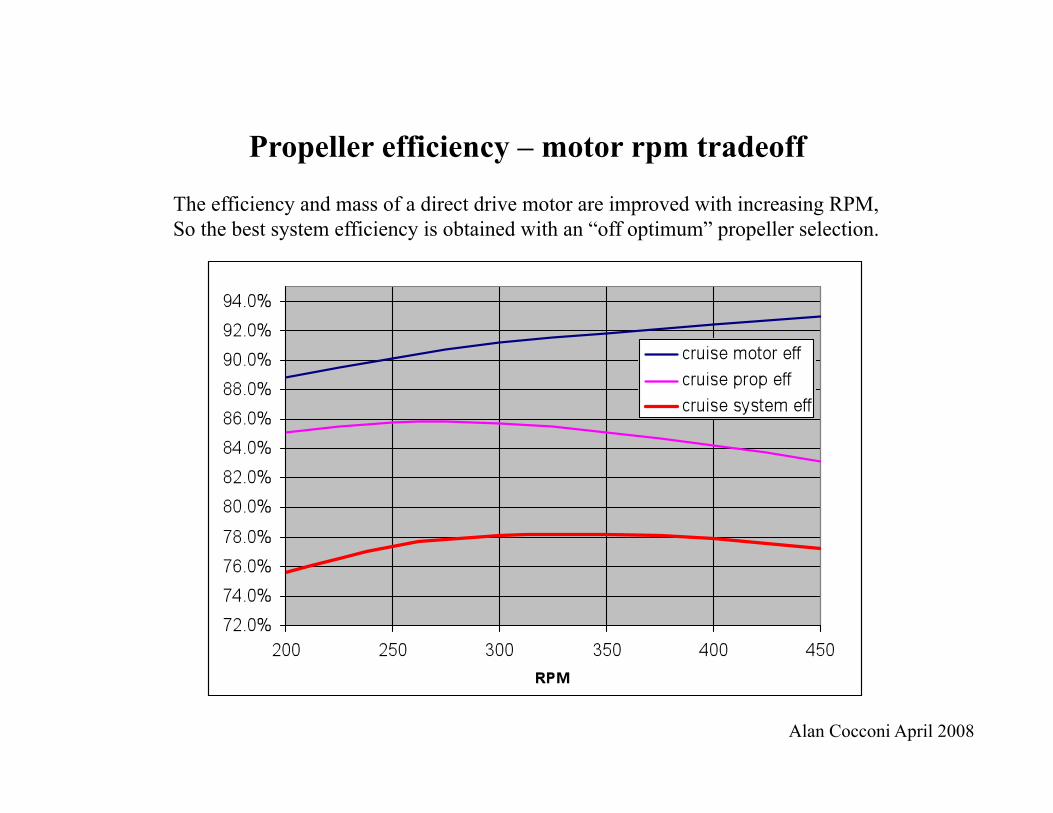
Propeller efficiency – motor rpm tradeoff The efficiency and mass of a direct drive motor are improved with increasing RPM, So the best system efficiency is obtained with an “off optimum” propeller selection.
Alan Cocconi April 2008

Propeller design issues As the propeller diameter is increased for improved efficiency for low speed propulsion 2 major problems are encountered:
1: Off axis inflow causes severe vibration and large moments on the motor shaft
2: The propeller operates at very low slip relative to the airstream, and feels very much like a wood screw pulling the aircraft though a solid airmass, with very small rpm changes for large power variations at a given airspeed, allowing poor use of the motor rpm range.

Propeller design solutions
1: A teetering or articulated blade propeller self aligns with the airflow and dramatically (by 10:1) reduces vibration levels in flight.
The Sunseeker was recently (2005) upgraded with a teetering propeller and the improvement over the original rigid blades was dramatic, allowing a safe relocation of the propeller 1 ft. further back from the tail to reduce interference.
2: Variable pitch allows the desired rpm increase to be available for max power, and improves the motor utilization and propeller efficiency.
The SoLong uses in-flight thrust measurement with a real time propulsive efficiency display to optimize the pitch variation with power setting. This system allows both efficiency optimization and provides a useful ongoing propulsion system performance check.

Motor mass - efficiency tradeoff
Motor efficiency can approach 100% as the mass approaches infinity, with diminishing improvement as the mass increases, so a rational tradeoff is needed.
For level flight the incremental power needed to balance a mass increase is 1.5 x the power loading .
Example: the SoLong UAV has a mass of 13kg and needs 75W for level flight.
The power loading is 5.8W/kg and the power: mass tradeoff is 8.7W/kg
The optimal motor design should have the matching slope of incremental loss reduction : mass increase
Alan Cocconi April 2008

Motor diameter- efficiency tradeoff
With direct drive motors the efficiency and mass may be optimal at a diameter that extends beyond the minimum fuselage or nacelle dimensions.
In these cases the motor design procedure must include the tradeoff between the estimated drag increase of a larger motor and the the incremental power savings from the increased efficiency
Alan Cocconi April 2008

Motor design program for
D double H Halbach A aferrous (ironless) R radial airgap M motor A assembly
In 2005 I began the development of motor design software to perform both the motor magnetics and winding design and the mass and drag tradeoffs for the DHARMA motor designs.
The model has been verified and fine tuned with 2 motors: 1: 800W, 4000 rpm, 80mm dia, 550g for the SoLong UAV 2: 15kW, 800 rpm, 430mm dia, 8.0kg for Piccard’s Solar Impulse
Alan Cocconi April 2008

Motor structure
The active mass (copper and magnets) needs to be rigidly supported with an efficient structure
Alan Cocconi April 2008
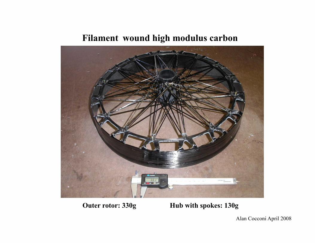
Filament wound high modulus carbon
Outer rotor: 330g Hub with spokes: 130g
Alan Cocconi April 2008

Mass: 465g
Motor mount with bearing tube and winding support
Alan Cocconi April 2008

Complete motor (on dyno for test)
71% active mass including the 4130 tube shaft and bearings. 8.0 kg total for 15kW and 180Nm max torque.
Alan Cocconi April 2008

Efficiency map
Actual dyno data including drive electronics efficiency:
Alan Cocconi April 2008

Dynamometer test setup
Alan Cocconi April 2008

Split Phase drive inverter
Ironless motors have a winding inductance that is approx. 10% that of a conventional motor
To keep ripple currents low an effective switching frequency >150kHz is needed
The Split phase inverter topology allows the use of lower switching frequencies for the individual transistors with a modest magnetics mass.
Packaged inverter mass: 2.0kg including magnetics for 15kW.
This was a key enabling technology For the 48 hour flight of the SoLong UAV in 2005.
Prototype of the 15kw Solar Impulse drive
Alan Cocconi April 2008