optimized manufacturing processes for cooler tank
TRANSCRIPT

Copyright © www.ijripublishers.com All Rights Reserved
OPTIMIZED MANUFACTURING PROCESSES FOR
COOLER TANK
MAGULURI NAGARJUNA [1] E. KAVITHA [2] ANOOSHA PEYYALA [3]
1Research Scholar, Department of Mechanical Engineering, P V P SIDDHARTHA INSTITUTE of TECHNOLOGY,(PVPSIT),kanuru Vijayawada, Andhra Pradesh ,India
2Assistant Professor, Department of Mechanical Engineering, P V P SIDDHARTHA INSTITUTE of TECHNOLOGY,(PVPSIT),kanuru Vijayawada, Andhra Pradesh ,India
3Assistant Professor, Department of Mechanical Engineering, P V P SIDDHARTHA INSTITUTE of TECHNOLOGY,(PVPSIT),kanuru Vijayawada, Andhra Pradesh ,India
ABSTRACT:
This project deals with the modeling of cooler tank parametric model as per the client requirement. Finding the best manufacturing
process preparing mould base for the same, analyzing different manufacturing process by doing CNC program by changing milling
parameters (feed, speed, cutters….).So that optimum parameters for manufacturing will be suggested which is useful to reduce the costs and efforts. Plastic flow analysis will be conducted to check the material flow
and filling. So that reduction in the pre-machining cost will be done by rectifying the problem. FEM Based analysis will be conducted on mould structure to reduce weight of the mould. And thermal analysis will be
conducted to suggest optimized cooling channel design. Modeling, mould base preparation, manufacturing, cnc programming will be done
Submitted on: 25-02-14 /Accepted on: 04-03-14 /published on: 15-03-14
INTERNATIONAL JOURNAL OF RESEARCH AND INNOVATION (IJRI))
1401-1402 VOL.1, ISSUE.2, MAR-APR. 2014
AVAILABLE ONLINE: WWW.IJRIPUBLISHERS.COM

Copyright © www.ijripublishers.com All Rights Reserved
INTRODUCTION:
Air coolers also called evaporative coolers are used for cooling purposes. They are different from air conditioners in the sense air conditioners use refrigeration cycle principle whereas air coolers use the evaporation of water principle. There are five main evaporative cooler parts, with each of these being composed of other parts or pieces. The first part is the Blower which creates the airflow into and out of the cooler. Then there are the pads which filter and cool the air. These pads are attached to the side grill; this grill is supported with side grill pillars and a mounting stand for motor. And the final part is bottom tank used to store water.
Figure 1 Air cooler
First, when the evaporative cooler is on, the pump circulates water from the tank of the cooler to the top. It filters down into the pads where some of it is absorbed, but what isn’t absorbed is passed down to the tank of the machine again where it will repeat
the cycle of being circulated again to the top. Some of the water will be evaporated from the pads and the circulating water will eventually be used up. So tank acts as a water reservoir in order to keep the pads damp if the pads ever dry out, the cooler will not be able to cool the air.
We have taken up the parameters of an already prepared air cooler and prepared a model for air cooler tank. And that mould tool design is done based on the model, by using Pro/engineer software. After determining the values of the mould tools, manufacturing drawings are prepared with full details selecting the appropriate materials. Subsequently, these mould tools are manufactured as per drawing prepared and subjected to quality control tests.
INTRODUCTION TO CAD
Computer Aided Design (CAD) is a technique in which man and machine are blended in to problem solving team, intimately coupling the best characteristics of each. The result of this combination works better than either man or machine would work alone , and by using a multi discipline approach, it offers the advantages of integrated team work.
The advances in Computer Science and Technology resulted in the emergence of very powerful hardware and software tool. It offers scope for use in the entire design process resulting in improvement in the quality of design. The emergency of CAD as a field of specialization will help the engineer to acquire the knowledge and skills needed in the use of these tools in an efficient and effective way on the design process.
Computer Aided Design is an interactive process, where the exchange of information between the designer and the computer is made as simple and effective as possible. Computer aided design encompasses a wide variety of computer based methodologies and tools for a spectrum of engineering activities planning, analysis, detailing, drafting, construction, manufacturing,

Copyright © www.ijripublishers.com All Rights Reserved
monitoring, management, process control and maintenance. CAD is more concerned with the use of computer-based tools to support the entire life cycle of engineering system.
INTRODUCTION TO PRO/ENGINEER
Pro/ENGINEER is a feature based, parametric solid modeling program. As such, it's use is significantly different from conventional drafting programs. In conventional drafting (either manual or computer assisted), various views of a
part are created in an attempt to describe the geometry. Each view incorporates aspects of various features (surfaces, cuts, radii, holes, protrusions) but the features are not individually defined. In feature based modeling, each feature is individually described then integrated into the part. The other significant aspect of conventional drafting is that the part geometry is defined by the drawing. If it is desired to change the size, shape, or location of a feature, the physical lines on the drawing must be changed (in each affected view) then associated dimensions are updated. When using parametric modeling, the features are driven by the dimensions (parameters). To modify the diameter of a hole, the hole diameter parameter value is changed. This automatically modifies the feature wherever it occurs - drawing views, assemblies, etc. Another unique attribute of Pro/ENGINEER is that it is a solid modeling program. The design procedure is to create a model, view it, assemble parts as required, then
generate any drawings which are required. It should be noted that for many uses of Pro/E, complete drawings are never created. A typical design cycle for a molded plastic part might consist of the creation of a solid model, export of an SLA file to a rapid prototyping system (stereo lithography, etc.), use of
the SLA part in hands-on verification of fit, form, and function, and then export of an IGES file to the molder or toolmaker. A toolmaker will then use the IGES file to program the NC machines which will directly create the mold for the parts. In many such design cycles, the only print created will be an inspection drawing with critical and envelope dimensions shown.
Summary of capabilities
Like any software it is continually being developed to include new functionality. The details below aim to outline the scope of capabilities to give an overview rather than giving specific details on the individual functionality of the product.
Pro/Engineer is a software application within the CAID/CAD/CAM/CAE category, along with other similar products currently on the market.
Engineering Design
Pro/Engineer offers a range of tools to enable the generation of a complete digital representation of the product being designed. In addition to the general geometry tools there is also the ability to generate geometry of other integrated design disciplines such as industrial and standard pipe work and complete wiring definitions. Tools are also available to support collaborative development.
Manufacturing
By using the fundamental abilities of the software with regards to the single data source principle, it provides a rich
set of tools in the manufacturing environment in the form of tooling design and simulated CNC machining and output.
Tooling options cover specialty tools for molding, die-casting and progressive tooling design.

Copyright © www.ijripublishers.com All Rights Reserved
MODEL OF AIR COOLER TANK
Sketch
First sketch of part
2D DRAWINGS OF COOLER TANK
Copyright © www.ijripublishers.com All Rights Reserved
INJECTION MOULDING
Injection moulding is a manufacturing process for producing parts from both thermoplastic and thermosetting plastic materials. Material is fed into a heated barrel, mixed, and forced into a mold cavity where it cools and hardens to the configuration of the mold cavity. After a product is designed, usually by an industrial designer or an engineer, molds are made by a mold maker (or toolmaker) from metal, usually either steel or aluminium, and precision-machined to form the features of the
desired part. Injection molding is widely used for manufacturing a variety of parts, from the smallest component to entire body panels of cars.
Process Characteristics
• Utilizes a ram or screw-type plunger to force molten plastic material into a mold cavity
• Produces a solid or open-ended shape which has conformed to the contour of the mold
• Uses thermoplastic or thermoset materials
• Produces a parting line, sprue, and gate marks
• Ejector pin marks are usually present
Injection molding is used to create many things such as wire spools, packaging, bottle caps, automotive dashboards, pocket combs, and most other plastic products available today.
Injection molding is the most common method of part manufacturing. It is ideal for producing high volumes of the same object. Some advantages of injection molding are high production rates, repeatable high tolerances, and the ability to use a wide range of materials, low labour cost, minimal scrap losses, and little need to finish
parts after molding. Some disadvantages of this process are expensive equipment investment, potentially high running costs, and the need to design moldable parts.
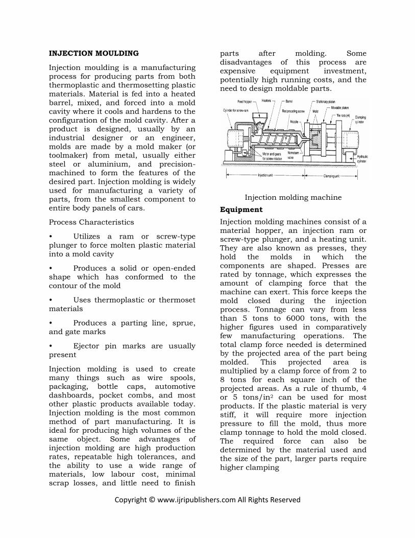
Injection molding machine
Equipment
Injection molding machines consist of a material hopper, an injection ram or screw-type plunger, and a heating unit. They are also known as presses, they hold the molds in which the components are shaped. Presses are rated by tonnage, which expresses the amount of clamping force that the machine can exert. This force keeps the mold closed during the injection process. Tonnage can vary from less than 5 tons to 6000 tons, with the higher figures used in comparatively few manufacturing operations. The total clamp force needed is determined by the projected area of the part being molded. This projected area is multiplied by a clamp force of from 2 to 8 tons for each square inch of the projected areas. As a rule of thumb, 4 or 5 tons/in2 can be used for most products. If the plastic material is very stiff, it will require more injection pressure to fill the mold, thus more clamp tonnage to hold the mold closed. The required force can also be determined by the material used and the size of the part, larger parts require higher clamping

Copyright © www.ijripublishers.com All Rights Reserved
Mold
Mold or die are the common terms used to describe the tooling used to produce plastic parts in molding.
Traditionally, molds have been expensive to manufacture. They were usually only used in mass production where thousands of parts were being produced. Molds are typically constructed from hardened steel, pre-hardened steel, aluminium, and/or beryllium-copper alloy. The choice of material to build a mold from is primarily one of economics, steel molds generally cost more to construct, but their longer lifespan will offset the higher initial cost over a higher number of parts made before wearing out. Pre-hardened steel molds are less wear resistant and are used for lower volume requirements or larger components. The steel hardness is typically 38-45 on the Rockwell-C scale. Hardened steel molds are heat treated after machining. These are by far the superior in terms of wear resistance and lifespan. Typical hardness ranges between 50 and 60 Rockwell-C (HRC). Aluminium molds can cost substantially less, and when designed and machined with modern computerized equipment, can be economical for molding tens or even hundreds of thousands of parts. Beryllium copper is used in areas of the mold which require fast heat removal or areas that see the most shear heat generated... The molds can be manufactured by either CNC
Machining
Molds are built through two main methods: standard machining and EDM. Standard Machining, in its conventional form, has historically been the method of building injection molds. With technological development, CNC machining became the predominant means of making more complex molds
with more accurate mold details in less time than traditional methods.
The electrical discharge machining (EDM) or spark erosion process has become widely used in mold making. As well as allowing the formation of shapes which are difficult to machine, the process allows pre-hardened molds to be shaped so that no heat treatment is required. Changes to a hardened mold by conventional drilling and milling normally require annealing to soften the steel, followed by heat treatment to harden it again. EDM is a simple
process in which a shaped electrode, usually made of copper or graphite, is very slowly lowered onto the mold surface (over a period of many hours), which is immersed in paraffin oil. A voltage applied between tool and mold causes spark erosion of the mold surface in the inverse shape of the electrode.
Injection process
With Injection Molding, granular plastic is fed by gravity from a hopper into a heated barrel. As the granules are slowly moved forward by a screw-type plunger, the plastic is forced into a heated chamber, where it is melted. As the plunger advances, the melted plastic is forced through a nozzle that rests against the mold, allowing it to enter the mold cavity through a gate and runner system. The mold remains cold so the plastic solidifies almost as soon as the mold is filled.
Time Function
The time it takes to make a product using injection molding can be calculated by adding: Twice the Mold Open/Close Time (2M) + Injection Time (T) + Cooling Time (C) +

Copyright © www.ijripublishers.com All Rights Reserved
Ejection Time (E) Where T is found by dividing: Mold Size (S) / Flow Rate (F) Total time = 2M + T + C + E T = V/R V = Mold cavity size (in3) R = Material flow rate (in3/min)
The total cycle time can be calculated using t cycle = t closing + t cooling + t ejection
The closing and ejection times, can last from a fraction of a second to a few seconds, depending on the size of the mold and machine. The cooling times, which dominate the process, depend on the maximum thickness of the part.
Lubrication and Cooling
Obviously, the mold must be cooled in order for the production to take place. Because of the heat capacity, inexpensiveness, and availability of water, water is used as the primary cooling agent. To cool the mold, water can be channeled through the mold to account for quick cooling times. Usually a colder mold is more efficient because this allows for faster cycle times. However, this is not always true because crystalline materials require the opposite of a warmer mold and lengthier cycle time
Applications
Injection molding is used to create many things such as milk cartons,
containers, bottle caps, automotive dashboards, pocket combs, and most other plastic products available today. Injection molding is the most common method of part manufacturing. It is ideal for producing high volumes of the same object. Some advantages of injection molding are high production
rates, high tolerances are repeatable, wide range of materials can be used, low labour cost, minimal scrap losses, and little need to finish parts after molding. Some disadvantages of this process are expensive equipment investment, running costs may be high, and parts must be designed with molding consideration.
Mold Design
The mold consists of two primary components, the injection mold (A plate) and the ejector mold (B plate). Plastic resin enters the mold through a sprue in the injection mold, the sprue bushing is to seal tightly against the nozzle of the injection barrel of the molding machine and to allow molten plastic to flow from the barrel into the mold, also known as cavity .The sprue bushing directs the molten plastic to the cavity images through channels that are machined into the faces of the A and B plates. These channels allow plastic to run along them, so they are referred to as runners. The molten plastic flows through the runner and enters one or more specialized gates and into the cavity geometry to form the desired part.
The amount of resin required to fill the sprue, runner and cavities of a mold is a shot. Trapped air in the mold can escaped through air vents that are grinded into the parting line of the mold. If the trapped air is not allowed to escape, it is compressed by the pressure of the incoming material and is squeezed into the corners of the cavity, where it prevents filling and causes other defects as well. The air can become so compressed that it ignites and burns the surrounding plastic material. To allow for removal of the molded part from the mold, the mold features must not overhang one another in the direction that the mold opens, unless parts of the mold are designed to move from between such

Copyright © www.ijripublishers.com All Rights Reserved
overhangs when the mold opens (utilizing components called Lifters).
Sides of the part that appear parallel with the direction of draw (The axis of the cored position (hole) or insert is parallel to the up and down movement of the mold as it opens and closes) are typically angled slightly with (draft) to ease release of the part from the mold. Insufficient draft can cause deformation or damage. The draft required for mold release is primarily dependent on the depth of the cavity: the deeper the cavity, the more draft necessary.
Shrinkage must also be taken into account when determining the draft required. If the skin is too thin, then the molded part will tend to shrink onto the cores that form them while cooling, and cling to those cores or part may warp, twist, blister or crack when the cavity is pulled away. The mold is usually designed so that the molded part reliably remains on the ejector (B) side of the mold when it opens, and draws the runner and the sprue out of the (A) side along with the parts. The part then falls freely when ejected from the (B) side. Tunnel gates, also known as submarine or mold gate, is located below the parting line or mold surface. The opening is machined into the surface of the mold on the parting line. The molded part is cut (by the mold) from the runner system on ejection from the mold. Ejector pins, also known as knockout pin, is a circular pin placed in either half of the mold (usually the ejector half) which pushes the finished molded product, or runner system out of a mold.
The standard method of cooling is passing a coolant (usually water) through a series of holes drilled through the mold plates and connected by hoses to form a continuous pathway. The coolant absorbs heat from the mold (which has absorbed heat from the hot plastic) and keeps the mold at a proper
temperature to solidify the plastic at the most efficient rate.
To ease maintenance and venting, cavities and cores are divided into pieces, called inserts, and sub-assemblies, also called inserts, blocks, or chase blocks. By substituting interchangeable inserts, one mold may make several variations of the same part.
More complex parts are formed using more complex molds. These may have sections called slides, that move into a cavity perpendicular to the draw direction, to form overhanging part features. When the mold is opened, the slides are pulled away from the plastic part by using stationary “angle pins” on the stationary mold half. These pins enter a slot in the slides and cause the slides to move backward when the moving half of the mold opens. The part is then ejected and the mold closes. The closing action of the mold causes the slides to move forward along the angle pins.
Injection mold design
Injection mold drawing

Copyright © www.ijripublishers.com All Rights Reserved
1. Locating Ring
2. Sprue Bushing
3. Top Clamping Plate
4. Angle Pin
5. Socket Head Bolt
6. A Plate
7. Guide Lock
8. Wedge Lock
9. Retainer
10. Dowel Pin
11. Wear Plate
12. Support Plate
13. Slide
14. Core Pin
15. Socket Head Bolt
16. Baffle
17. '8' Plate
18. Ejector Retainer Plate
19. Ejector Pin
20. Stop Pin
21. Ejector Plate
22. Ejector Housing
23. Return Spring
24. Return Pin
25. Cooling Channel
26. Ejector Shaft
Clamping Unit in Injection
molding machine
The clamping unit holds the mold together, opens and closes it automatically, and ejects the finished part. The mechanism may be of several designs, mechanical, hydraulic or hydro mechanical.
Clamping Units.
Clamping designs are of three types: toggle, hydraulic, and hydro mechanical. Toggle clamps include various designs. An actuator moves the
crosshead forward, extending the toggle links to push the moving platen toward a closed position. At the beginning of the movement, mechanical advantage is low and speed is high; but near the end of the stroke, the reverse is true. Thus, toggle clamps provide both high speed and high force at different points in the cycle when they are desirable. They are actuated either by hydraulic
Figure 59 Clamping unit
Hydraulic clamps are used on higher-tonnage injection-molding machines,
typically in the range 1300 to 8900 kN (150 to 1000 tons). These units are also more flexible than toggle clamps in terms of setting the tonnage at given positions during the stroke. Hydro mechanical clamps are designed for large tonnages, usually above 8900 kN (1000 tons.

Copyright © www.ijripublishers.com All Rights Reserved
Injection Molding Cycle & Process
The injection molding process occurs cyclically. Typical cycle times range from 10 to 100 seconds and are controlled by the cooling time of the thermoplastic or the currying time of the thermosetting plastic. The plastic resin in the form of pellets or powder is fed from the hopper and melted. In a reciprocating screw type injection molding machine, the screw rotates forward and fills the mold with melt, holds the melt under high pressure, and adds more melt to compensate for
the contraction due to cooling and solidification of the polymer. This is called the hold time. Eventually the gate freezes, isolating the mold from the injection unit, the melt cools and solidifies. Next the screw begins to rotate and more melt is generated for the next shot. In the soak time the screw is stationary and the polymer melts by heat conduction from the barrel to the polymer. The solidified part is then ejected and the mold closes for the next shot.
Step #1 - The
uncured rubber
is fed into the machine in the
form of a
continuous
strip.
Step #2 - The uncured rubber
is worked and
warmed by an
auger screw in
a temperature
controlled
barrel.
Step #3 - As
the rubber
stock accumulates in
the front of the
screw, the
screw is forced
backwards.
When the screw has moved
back a specified
amount, the
machine is
ready to make a
shot.
Step #4 - With the mold held
closed under
hydraulic
pressure, the
screw is pushed
forward. This forces the
rubber into the
mold, similar to
the action of a
hypodermic
syringe.
Step #5 - While the rubber cures in the heated mold, the screw turns again to refill.
Step #6 - The
mold opens and the part can be
removed. The
machine is
ready to make
the next shot,
as soon as the
mold closes.
Copyright © www.ijripublishers.com All Rights Reserved
MOULD CALCULATIONS
Clamping Tonnage
Fc = Pc×Ap×n
Fc = clamping tonnage .( tons)
Pc = Cavity pressure = 550 Kg/ cm2 =55 kg/ cm2
Ap = projected area = 1.3477369 m2 = 13477.369 cm2
n = no. of cavity =1
Fc = 55 kg/cm2×13477.369 cm2×1
= 741255.295 kg = 741.255 tons
Available tonnage = 1103
As per machine standards = 1103 tons
= 1103×0.85
= 937.55 tons
741.255T<937.55T
J1000AD (JAD series)
Mold height = 500 to 1200 mm
Based on the shot capacity
Shot weight = 635×density of PA-6/density of PS
= 635×(1.45/1.05)
= 876.3 gm
Considering the Factor of safety 85% only
= 876.3×0.85 = 744.855
Cooling calculations
Q = Heat to be transferred per hour by plastic Material
Q = Mp×a Cal /hr
Mp = Mass of plastic Material injected into mold per hour in gms/hr
a = heat content of plastic in Cal/gm = 50
Mp = Shot weight × no.of cycles per/hr
No.of cycles per /hr
59.90sec/comp filling time = 60 sec
Ejection time = 30 sec
3600sec/hr/90 per/comp = 40 comp
Mp = 744.855×40 = 29794.2
Q = 29794.2×130
Q = 387324.6 Cal/hr
Qw = Rate of heat to be extracted by water in Cal/hr
K = the constant to allow heat transfer efficiency
Mw = Mass of water circulated in gms / hr
Qw = Mw × K(tout –tin) 50
For direct cooling method = 0.64
Indirect method = 0.50
Qw = Mw × K(tout –tin)
= Q/2
Mw = 1716000/2×0.64×5
= 268125 gm/hr
= 268.125 lit/hr
Copyright © www.ijripublishers.com All Rights Reserved
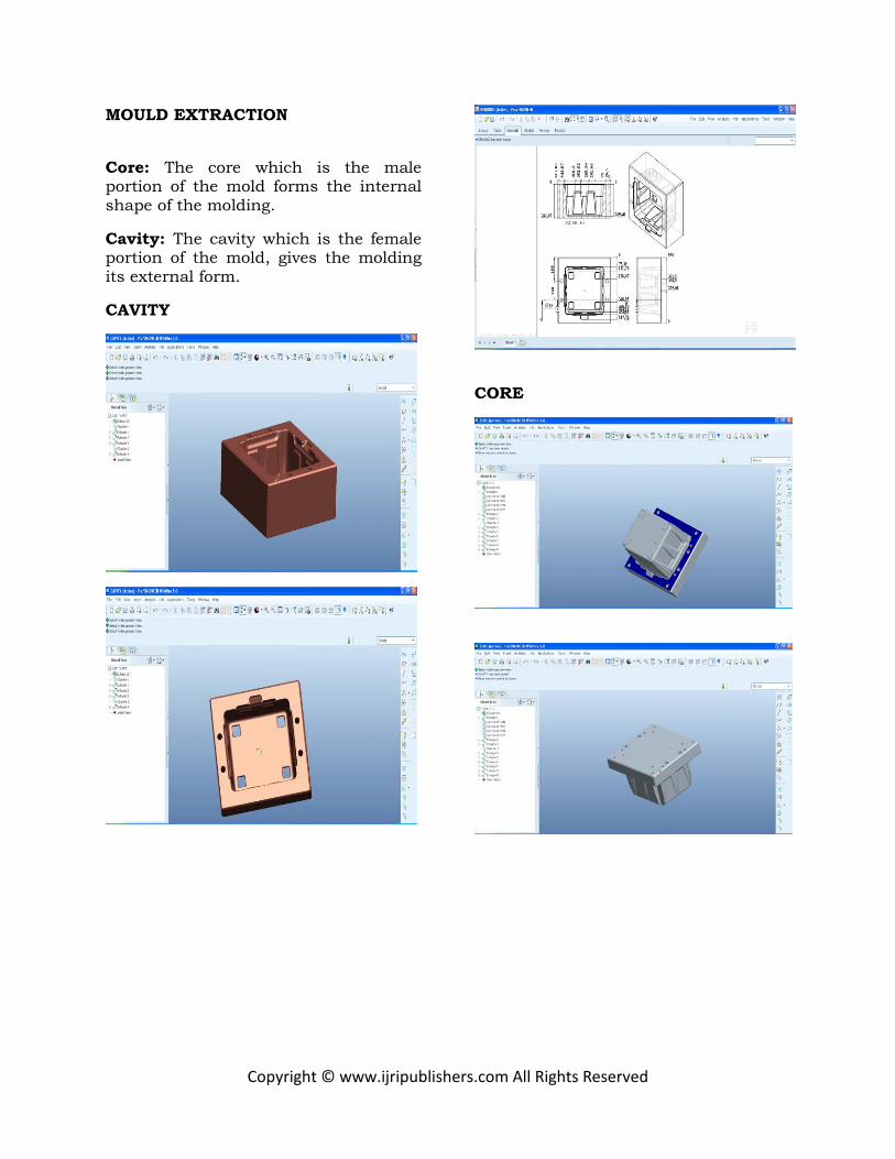
MOULD EXTRACTION
Core: The core which is the male portion of the mold forms the internal shape of the molding.
Cavity: The cavity which is the female portion of the mold, gives the molding its external form.
CAVITY
CORE

Copyright © www.ijripublishers.com All Rights Reserved
DIE DESIGN
Cavity Back Plates - Plates used as a support for the mold cavity block, core block.
Ejector Plate – Ejector plate is used for pushing ejector pins, retainer plate etc
Ejector Pins - Pins that are pushed into a mold cavity from the rear as the mold opens to force the finished part out of the mold.
Ejector Pin
Retainer Plate - The plate on which demountable pieces, such as mold cavities, ejector pins, retainer pins are mounted during molding.

Copyright © www.ijripublishers.com All Rights Reserved
Retainer Pins – Retainer pins are used to push the retainer plate.
Retainer Pin
Guide bush Guide Pillar
Guide Sleeves
2D drawings:

Copyright © www.ijripublishers.com All Rights Reserved
DIE ASSEMBLY

Copyright © www.ijripublishers.com All Rights Reserved
MOULD FLOW ANALYSIS
Physical Properties
Metric
Density 0.920 g/cc
Linear Mold Shrinkage
0.012 cm/cm
Melt Flow 11 g/10 min
Ash 10 %
Mechanical Properties
Metric
Hardness, Rockwell R
68
Tensile Strength at Break
18.0 MPa
Tensile Strength, Yield
22.0 MPa
Elongation at Break 168 %
Elongation at Yield 5.0 %
Tensile Modulus 1.20 GPa
Flexural Strength 25.0 MPa
Flexural Modulus 1.00 GPa
Izod Impact, Notched
1.28 J/cm
Thermal Properties
Metric
Deflection Temperature at 0.46 MPa (66 psi)
52.8 °C
Deflection Temperature at 1.8 MPa (264 psi)
87.8 °C
PLASTIC ADVISOR in PRO/ENGINEER
Problems found after tooling development are always expensive and frustrating. For plastic part design and manufacture, there is a better way. By simulating the plastic-filling process for injection-molded parts, Pro/ENGINEER Plastic Advisor enables engineers to design for manufacturability, uncover problems, and propose remedies, reducing development time and expense.
Features & Benefits
• Animates plastic injection fill process and automatically creates Web reports within Pro/ENGINEER browser
• Access library of common plastic materials and automatically select from typical injection-molding machine parameters
• Identify optimal injection locations to reduce cycle time and improve product appearance
• Identify potential mold-filling problems such as short shots, air traps, and weld lines
• Improve design quality and reduces manufacturing cycle times and rework of molds
4-INJECTIONS:
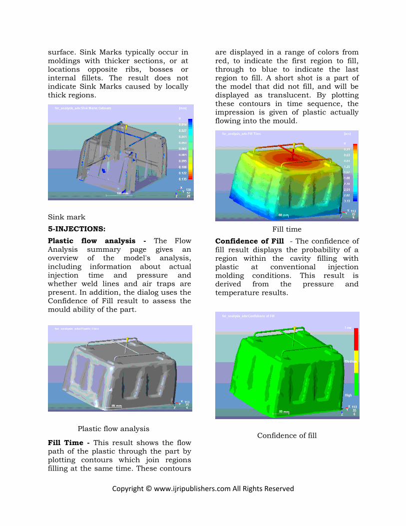
Plastic flow analysis
The Flow Analysis summary page gives an overview of the model's analysis, including information about actual injection time and pressure and whether weld lines and air traps are present. In addition, the dialog uses the Confidence of Fill result to assess the mould ability of the part.
Plastic flow analysis
Fill Time - This result shows the flow path of the plastic through the part by plotting contours which join regions filling at the same time. These contours are displayed in a range of colors from red, to indicate the first region to fill, through to

Copyright © www.ijripublishers.com All Rights Reserved
blue to indicate the last region to fill.
Fill time
Confidence of Fill - The confidence of fill result displays the probability of a region within the cavity filling with plastic at conventional injection molding conditions. This result is derived from the pressure and temperature results.
Confidence of fill
Injection pressure
Flow Front Temperature - The flow front temperature result uses a range of colors to indicate the region of lowest temperature (colored blue) through to the region of highest temperature (colored red). The colors represent the material temperature at each point as that point was filled. The result shows the changes in the temperature of the flow front during filling.
Quality indication
Weld Line - This result indicates the presence and location of weld and weld lines in the filled part model. These are places where two flow fronts have converged. The presence of weld and weld lines may indicate a weakness or blemish.

Copyright © www.ijripublishers.com All Rights Reserved
Weld line
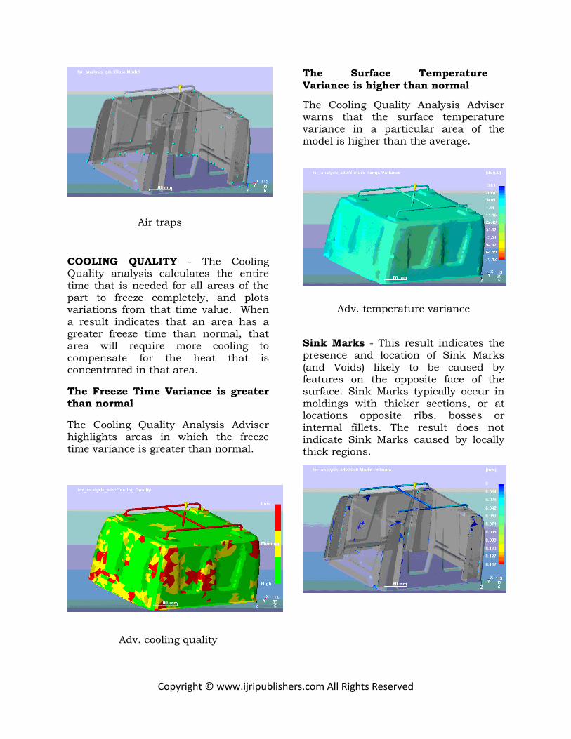
Air Traps - The air trap result shows the regions where the melt stops at a convergence of at least 2 flow fronts or at the last point of fill, where a bubble of air becomes trapped. The regions highlighted in the result are positions of possible air traps.
Air traps
COOLING QUALITY - The Cooling
Quality analysis calculates the entire time that is needed for all areas of the part to freeze completely, and plots variations from that time value. When a result indicates that an area has a greater freeze time than normal, that area will require more cooling to
compensate for the heat that is concentrated in that area.
The Freeze Time Variance is greater than normal
The Cooling Quality Analysis Adviser highlights areas in which the freeze time variance is greater than normal.
Adv. cooling quality
The Surface Temperature Variance is higher than normal
The Cooling Quality Analysis Adviser warns that the surface temperature variance in a particular area of the model is higher than the average.
Adv. temperature variance
Sink Marks - This result indicates the presence and location of Sink Marks (and Voids) likely to be caused by features on the opposite face of the
Copyright © www.ijripublishers.com All Rights Reserved
surface. Sink Marks typically occur in moldings with thicker sections, or at locations opposite ribs, bosses or internal fillets. The result does not indicate Sink Marks caused by locally thick regions.
Sink mark
5-INJECTIONS:
Plastic flow analysis - The Flow Analysis summary page gives an overview of the model's analysis, including information about actual injection time and pressure and whether weld lines and air traps are present. In addition, the dialog uses the Confidence of Fill result to assess the mould ability of the part.
Plastic flow analysis
Fill Time - This result shows the flow path of the plastic through the part by plotting contours which join regions filling at the same time. These contours
are displayed in a range of colors from red, to indicate the first region to fill, through to blue to indicate the last region to fill. A short shot is a part of the model that did not fill, and will be displayed as translucent. By plotting these contours in time sequence, the impression is given of plastic actually flowing into the mould.
Fill time
Confidence of Fill - The confidence of fill result displays the probability of a region within the cavity filling with plastic at conventional injection molding conditions. This result is derived from the pressure and temperature results.
Confidence of fill

Copyright © www.ijripublishers.com All Rights Reserved
Injection pressure
Flow Front Temperature - The flow front temperature result uses a range of colors to indicate the region of lowest temperature (colored blue) through to the region of highest temperature (colored red). The colors represent the material temperature at each point as that point was filled. The result shows the changes in the temperature of the flow front during filling.
Quality indication
Weld Line - This result indicates the
presence and location of weld and weld lines in the filled part model. These are places where two flow fronts have converged. The presence of weld and weld lines may indicate a weakness or blemish.
Weld line
Air Traps - The air trap result shows the regions where the melt stops at a convergence of at least 2 flow fronts or at the last point of fill, where a bubble of air becomes trapped. The regions highlighted in the result are positions of
possible air traps.
Copyright © www.ijripublishers.com All Rights Reserved
Air traps
COOLING QUALITY - The Cooling Quality analysis calculates the entire time that is needed for all areas of the part to freeze completely, and plots variations from that time value. When a result indicates that an area has a greater freeze time than normal, that area will require more cooling to compensate for the heat that is concentrated in that area.
The Freeze Time Variance is greater
than normal
The Cooling Quality Analysis Adviser highlights areas in which the freeze time variance is greater than normal.
Adv. cooling quality
The Surface Temperature
Variance is higher than normal
The Cooling Quality Analysis Adviser warns that the surface temperature variance in a particular area of the model is higher than the average.
Adv. temperature variance
Sink Marks - This result indicates the presence and location of Sink Marks (and Voids) likely to be caused by features on the opposite face of the surface. Sink Marks typically occur in moldings with thicker sections, or at locations opposite ribs, bosses or internal fillets. The result does not indicate Sink Marks caused by locally thick regions.

Copyright © www.ijripublishers.com All Rights Reserved
INTRODUCTION TO ANSYS
ANSYS is general-purpose finite element analysis (FEA) software package. Finite Element Analysis is a numerical method of deconstructing a complex system into very small pieces (of user-designated size) called elements. The software implements equations that govern the behavior of these elements and solves them all; creating a comprehensive explanation of how the system acts as a whole. These results then can be presented in tabulated, or graphical forms. This type of analysis is typically used for the design and optimization of a system far too complex to analyze by hand. Systems that may fit into this category are too complex due to their geometry, scale, or governing equations.
ANSYS is the standard FEA teaching tool within the Mechanical Engineering Department at many colleges. ANSYS is also used in Civil and Electrical Engineering, as well as the Physics and Chemistry departments.
With virtual prototyping techniques, users can iterate various scenarios to optimize the product long before the manufacturing is started. This enables a reduction in the level of risk, and in the cost of ineffective designs. The multifaceted nature of ANSYS also provides a means to ensure that users are able to see the effect of a design on the whole behavior of the product, be it electromagnetic, thermal, mechanical etc.
Steps involved in ANSYS:
In general, a finite element solution can be broken into the following these categories. 1. Preprocessing module: Defining the
problem The major steps in preprocessing are given below - defining key points /lines/areas/volumes - define element type and material /geometric /properties - mesh lines/areas/volumes/are required The amount of detail required will depend on the dimensionality of the analysis (i.e. 1D, 2D, axis, symmetric) 2. Solution processor module: assigning the loads, constraints and solving. Here we specify the loads, constraints and finally solve the resulting set of equations. 3. Post processing module: further processing and viewing of results In this stage we can see: List of no coupled-field analysis dal displacement Elements forces and moments Deflection plots Stress contour diagrams
Overview of coupled-field analysis
A coupled-field analysis is an analysis that takes into account the interaction (coupling) between two or more disciplines (fields) of engineering. A piezoelectric analysis, for example, handles the interaction between the structural and electric fields: it solves for the voltage distribution due to applied displacements, or vice versa. Other examples of coupled-field analysis are thermal-stress analysis, thermal-electric analysis, and fluid-structure analysis.
Some of the applications in which coupled-field analysis may be required are pressure vessels (thermal-stress analysis), fluid flow constrictions, induction heating (magnetic-thermal analysis), ultrasonic transducers, and magnetic forming (magneto-structural analysis)

Copyright © www.ijripublishers.com All Rights Reserved
STRUCTURAL ANALYSIS OF
STANDARD MOULD
The above image is the imported model of
composite shaft. Modeling was done in
Pro-E and imported with the help of IGES (Initial Graphical Exchanging
Specification).
Material: EN 38
Element Type: Solid 20 nodes 95 Material Properties: Young’s Modulus (EX) : 20900N/mm2
Poissons Ratio (PRXY : 0.27 Density : 0.000007876kg/mm3
Meshed Model
The above image showing the meshed
modal. Default solid Brick element was
used to mesh the components. The shown
mesh method was called Tetra Hydra Mesh.
Meshing is used to deconstruct complex problem into number of small problems
based on finite element method.
Loads 1000000*9.81=9810000
AREA 621152mm2
Pressure – 15.79N/mm2
The above image is showing the loads applied on a mold
Solution
Solution – Solve – Current LS – ok
Post Processor
General Post Processor – Plot Results – Contour Plot - Nodal Solution – DOF Solution – Displacement Vector Sum
The above image shows the displacement, value is 0.007979mm

Copyright © www.ijripublishers.com All Rights Reserved
The above image shows the stress, value is 5.61561N/mm2
STRUCTURAL ANALYSIS OF REDUCED THICKNESS
The above image shows the displacement, value is 0.008118mm
The above image shows the stress, value is 5.6919N/mm2
STRUCTURAL ANALYSIS OF
REDUCED THICKNESS TWO
The above image shows the displacement, value is 0.008713mm
The above image shows the stress, value is 10.5942N/mm2
THERMAL ANALYSIS FOR STANDARD MOULD

Copyright © www.ijripublishers.com All Rights Reserved
The above image is the imported model of composite shaft. Modeling was done in Pro-E and imported with the help of IGES (Initial Graphical Exchanging Specification).
The above image showing the meshed modal. Default solid Brick element was used to mesh the components. The shown mesh method was called Tetra Hydra Mesh.
Meshing is used to deconstruct complex problem into number of small problems based on finite element method.
Loads
Molten material Temp 513k
Mould temp 313
The above image shows the melted material temperature
The above image shows the cooling channel temperature
The above images shows the contact area with air
Results
The above image shows the nodal temperature

Copyright © www.ijripublishers.com All Rights Reserved
The above image shows the thermal gradient
The above image shows the Thermal flux
THERMAL ANALYSIS FOR MODIFIED COOLING CHANNAL
Nodal temp
The above image shows the nodal temperature
The above image shows the thermal
gradient
The above image shows the Thermal flux
MANUFACTURING PROCESS
By designed the mould tool for air cooler tank, with the parameters now we can manufacture the air cooler tank according to the dimensions. The flow chart of the manufacturing process of the air cooler tank is given below.

Copyright © www.ijripublishers.com All Rights Reserved
Raw material
Hot die steels are most commonly used mould tool materials. they have Excellent toughness, ductility and harden ability .Used for vary large dies especially in thickness greater than 200mm .Also used for hot and warm forging and in extrusion tooling such as intricate dies and also dummy block ,liners, etc.
Surface grinding
After selecting raw material surface grinding is done, Surface Grinding is a widely used process of machining in which a spinning wheel covered in rough particles cuts chips of metallic or non-metallic substance making them flat or smooth.
Heat treatment
To increase the strength of the material it is heat treated. Heat treatment is an important operation in the manufacturing process of machine parts and tools. Heat Treatment is the controlled heating and cooling of metals to alter their physical and mechanical properties without changing the product shape.
CNC machining
In modern CNC systems, end-to-end component design is highly automated using CAD/CAM programs. The programs produce a computer file that is interpreted to extract the commands needed to operate a particular machine, and then loaded into the CNC machines for production. Since any particular component might require the use of a number of different tools - drills, saws, etc. - modern machines often combine multiple tools into a single "cell". In other cases, a number of different machines are used with an external controller and human or robotic operators that move the component from machine to machine. In either case the complex series of steps needed to produce any part is highly automated and produces a part that closely matches the original CAD design. After undergoing CNC machining process the mold tool i.e. core and cavity are shown in following figures.

Copyright © www.ijripublishers.com All Rights Reserved
Cavity
Core
Air cooler tank
MANUFACTURING PROCESS
CORE ROUGHING WORKPIECE
CUTTING TOOL
PLAY PATH
VERICUT
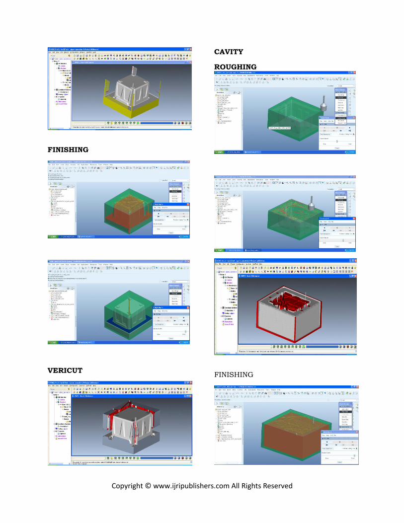
Copyright © www.ijripublishers.com All Rights Reserved
FINISHING
VERICUT
CAVITY
ROUGHING
FINISHING

Copyright © www.ijripublishers.com All Rights Reserved
ANALYSIS RESULT TABLE
Structural analysis
Displacement in mm
Stress In N/mm2
Standard mold
0.007979 5.61561
Reduced thickness
0.008118 5.6919
Reduced thickness two
0.008713 10.5942
Thermal analysis
Thermal gradient
Thermal flux
Nodal temperature
Standard mold
240.348
12.4981
513
Modified
cooling
260.20
7
13.530
8 513
TIME FOR MACHAINING (milling) PROCESSES Cavity roughing process
=209397.32sec
Finishing process time
= 17337.18sce
Total time 63hrs
Core roughing process time
=586735.8se
Core finishing time
=16011.62sec
Total time
=167hrs
Overall cost: 230(hours)*300(per hour) = Rs 69,000
Weight and cost table for existing
model
INDEX MATERIAL NAME
QUANTITY & PRICE
COST
bolts
C22 carbon steel alloy
1.516KG X275 Rs
416.00 /-
plates MS tool grade
754.67 KG X175 Rs
1,32,067.00/-
Die set (core& cavity)
HARDND STEEL
884.69KG X 375 Rs
331758.75/-
Guide
pins OHNS
7.508 X
325 Rs 2460.00/-
GUIDE SLEEVES
GUIDE SLEEVES
6NOS X 500Rs
3000.00/-
GUIDE PILLERS
GUIDE PILLERS
6 X 1300Rs
7800/-
WATER INLET KNOBS
WATER INLET KNOBS
12 X150 Rs
3600/-
TOTAL 4,81,102.00/-
Weight and cost table for reduced thickness 1
INDEX MATERIAL NAME
QUANTITY & PRICE
COST
Bolts C22 carbon steel alloy for bolts
1.516KG X275 Rs
416.00 /-
Plates MS tool grade
700.40 KG X175 Rs
1,22,570.00/-
Die set (core& cavity)
HARD AND STEEL
884.69KG X 375 Rs
331758.75/-
Guide pins
OHNS 7.508 X 325 Rs
2460.00/-
GUIDE SLEEVES
GUIDE SLEEVES
6NOS X 500Rs
3000.00/-
GUIDE
PILLERS
GUIDE
PILLERS
6 X
1300Rs
7800/-
WATER INLET KNOBS
WATER INLET KNOBS
12X150 Rs
3600/-
TOTAL 4,71,604.75/-

Copyright © www.ijripublishers.com All Rights Reserved
Weight and cost table for reduced
thickness 2
INDEX MATERIAL NAME
QUANTITY & PRICE
COST
bolts
C22 carbon steel alloy
1.516KG X275 Rs
416.00 /-
plates MS tool grade
646.60 KG X175 Rs
1,13,155.00/-
Die set (core& cavity)
HARD AND STEEL
884.69KG X 375 Rs
331758.75/-
Guide
pins OHNS
7.508 X
325 Rs 2460.00/-
GUIDE SLEEVES
GUIDE SLEEVES
6NOS X 500Rs
3000.00/-
GUIDE PILLERS
GUIDE PILLERS
6 X 1300Rs
7800/-
WATER INLET KNOBS
WATER INLET KNOBS
12 X150 Rs
3600/-
TOTAL 4,62,189.75/-
CONCLUSION
• In this project, designed an air cooler water tank as per the parameters; tank capacity is 15 liters, width 380mm, length 420mm, and height 260mm.
• Core and Cavity is extracted for the tank.
• Die design is prepared for the same.
• The modeling, core-cavity extraction and die design is done in PRO/ENGINEER.
• Mould Flow Analysis is done on water tank
• Mould flow analysis for finding the material filling, pressure distribution, air traps, wild lines formed during injection moulding process.
• Mould Flow Analysis is done using “Plastic Advisor” which is a module in Pro/Engineer.
• By simulating the plastic-filling process for injection-molded parts, Pro/ENGINEER Plastic Advisor enables engineers to design for manufacturability, uncover problems, and propose remedies, reducing development time and expense.
• By using this process manufacture of air cooler tank can be done without any failures….
• Static and thermal analysis is conducted on mould structure for weight reduction and for optimized cooling channels.
• As per the analytical results reduction of spacer housing thickness and reduction of core back support is also performing well, so better to use reduced thk 2 model for cast and weight reduction.
• Optimized location is the better
option for thermal behavior because of high flux and gradient rates.
• By reducing plate sizes company can reduce upto Rs.19,000/-
450000
460000
470000
480000
490000
#REF!
reduced thk 1
reduced thk 2
Copyright © www.ijripublishers.com All Rights Reserved
Refarence
1)Machine design ,T.V. Sundararaja moorthy 2) Machine design, R.S.Khurmi /J.K.Guptha (S.CHAND) 3) Design data book: P.S.G.College of Technology (Kalaikathirachchagam), 4) Design of machine element: V.B.Bandari ( TATA McGraw-hill) 5) Injection mould design: R.G.W. PYE (East-West press Pvt. Ltd) [6] On Optimization of Injection Molding Cooling Lars-Erik Rännar Thesis for the degree doktor ingeniør Trondheim, April 2008 Norwegian University of Science and Technology Faculty of Engineering Science and Technology Department of Engineering Design and Materials [7] Multidisciplinary optimization of injection molding systems Irene Ferreira • Olivier de Weck •Pedro Saraiva. José Cabral Struct Multidisc Optim (2010) 41:621–635DOI 10.1007/s00158-009-0435- [8] Injection Mold Design and Optimization of Battery Air vent Rahul S. Khichadi M.Tech student, VACOE Ahmednagar, Maharashtra, India-414201 [9] Effective Run-In and Optimization of an Injection Molding Process Stefan Moser. Moser Process Consulting, Germany [10] Recent Methods for Optimization of Plastic Injection Molding Process - A Literature Review Rashi A.Yadav Reserach Scholar, Principal S.V.Joshi, Asst. Prof. N.K.Kamble
Production Engineering Department D.Y.Patil College of Engineering, Akurdi, Pune – 44 MH. India
Authors
MAGULURI NAGARJUNA
(M.Tech (Machine Design))
Research scholar from,
department of mechanical
engineering,
P V P SIDDHARTHA INSTITUTE
Of TECHNOLOGY, kanuru,
Vijayawada, Krishna dist,
Andhra Pradesh ,India
Email ID:
E. Kavitha
Assistant Professor
Mechanical Engineering
M.Tech (CAD/CAM)
Teaching Experience: 6 years
(in PVPSIT College, kanuru)
Vijayawada, Krishna dist,
Andhra Pradesh, India
Anoosha Peyyala
Mechanical Engineering,
Assistant Professor
M.Tech - Mechanical
Teaching Experience: 3 years
(in PVPSIT College, kanuru)
Vijayawada, Krishna dist,
Andhra Pradesh, India