optimizing asf code size to minimize flash and ram...
TRANSCRIPT

APPLICATION NOTE
AT08569: Optimizing ASF Code Size to Minimize Flash and RAM Usage
Atmel Microcontroller
Features
• ASF Application Sizing Considerations • Compiler and Build Options • Approaches to Reduce Flash Requirements • Approaches to Reduce RAM Requirements
Introduction
The Atmel® Software Framework (ASF) is a set of source files, libraries, and reference projects that enable rapid development of application code that runs on, and interfaces with, a wide range of Atmel microcontrollers.
The ASF provides the build configuration and peripheral driver framework necessary to host an application, allowing the application’s writer to focus development time solely on creating core functionality.
The primary ASF design objective is to demonstrate the full features of the integrated microcontroller peripherals. Full featured services and drivers allow the application writer to quickly match software requirements to complex application requirements. It often saves hours of datasheet research and enables rapid prototyping of difficult programming problems.
An unfortunate side effect of full-featured drivers is that they require more memory resources than those dedicated to a specific function. In aggregate, these drivers and services in combination with the final application can exceed available memory resources. Finalizing the configuration of an application presents plenty of opportunities to optimize the code for a smaller footprint. ASF is a general solution that works across many architectures, and is written to illustrate how to use most of the features Atmel microcontrollers provide. A single application typically only needs a subset of this functionality, and when space gets tight, there are a number of ways to take advantage of application-specific requirements to tune (cut features out) of the Atmel Software Framework implementation.
This application note explores various approaches to minimizing ASF application memory requirements.
Atmel-42370A-Optimizing-ASF-Code-Size-to-Minimize-Flash-and-RAM-Usage_ApplicationNote_092014
Optimizing ASF Code Size to Minimize Flash and RAM Usage [APPLICATION NOTE] Atmel-42370A-Optimizing-ASF-Code-Size-to-Minimize-Flash-and-RAM-Usage_ApplicationNote_092014
2
Table of Contents
1 ASF Sizing Considerations ......................................................................................... 3 1.1 ASF Features and Size ......................................................................................................................... 3 1.2 Memory Requirements .......................................................................................................................... 3
1.2.1 Static Memory Requirements ................................................................................................... 3 1.2.2 Dynamic Memory Requirements .............................................................................................. 6
1.2.2.1 LwIP .......................................................................................................................... 6 1.2.2.2 FreeRTOS ................................................................................................................ 7
2 Reducing ASK Application Memory Requirements with Tools ................................ 8 2.1 Microcontroller Selection ....................................................................................................................... 8 2.2 Toolchain Selection and Tuning ............................................................................................................ 9
2.2.1 Toolchain Benchmarks ........................................................................................................... 10 2.2.2 Toolchain Build Options .......................................................................................................... 10 2.2.3 Embedded C Library Selection ............................................................................................... 11
3 Reducing Application Flash Requirements ............................................................. 12 3.1 ASF Wizard Component Removal ...................................................................................................... 12 3.2 Dependency Tracing and Scaling out Functionality ............................................................................ 13 3.3 Simplifying Code ................................................................................................................................. 14 3.4 Example .............................................................................................................................................. 15
4 Reducing Application RAM Requirements .............................................................. 16 4.1 Data Segment and Constant Data ...................................................................................................... 16 4.2 Stack Allocation Tuning ....................................................................................................................... 16 4.3 Preemptive vs. Cooperative Scheduling .............................................................................................. 16
5 Revision History ........................................................................................................ 18

Optimizing ASF Code Size to Minimize Flash and RAM Usage [APPLICATION NOTE] Atmel-42370A-Optimizing-ASF-Code-Size-to-Minimize-Flash-and-RAM-Usage_ApplicationNote_092014
3
1 ASF Sizing Considerations When provisioning an application with desired services and middleware it is often the case that the resulting images size exceeds available memory resources of the selected microcontroller. There are a number of remedies explored in this application note. There is no single approach that suits a specific application, but in this survey, techniques described may prove handy when reducing the size of ASF. The reader is assumed to have full knowledge of their system architecture and requirements. Size reduction is the art of balancing trade-offs in functionality, portability, and performance, and determining an optimal solution can involve considerable trial and error. To help this process, we focus first on how to determine the size of an application and what ASF components contribute to this size.
1.1 ASF Features and Size The ASF Explorer (or Wizard) within Atmel Studio is the primary interface to select or deselect ASF functionality to be included in an Atmel Studio Project. It is important to stress that some ASF components depend upon other ASF components lower in the ASF software stack. When such a higher level ASF component is selected, all subcomponents that are depended upon are automatically added to the project. This can lead to some surprises. The inclusion of one ASF component may drag in unexpected functionality.
Start by closely examining the ASF Explorer to see all of the components that are currently configured into an Atmel Studio project. Make every effort to remove superfluous components by reducing application requirements wherever possible. For instance, is the software floating-point emulation included only for the purposes of supporting printf()? Without some care printf() supports the formatting of floating point numbers (“%f”) and it will drag in the necessary libraries to support this functionality. ANSI C library support will be further discussed below.
A straightforward approach is to simply select and deselect functionality, and determine what application functionality is missing and whether it is strictly required. Uncheck an ASF component, rebuild the solution, and determine whether the application can be simplified. This trial and error approach can work two ways. One can start with a full application and begin deselecting features in an effort to reduce project size. Alternatively, one can start with a very basic starting point, and incrementally add the ASF functionality required to re-create the full application. This latter approach will allow for a feature-by-feature estimation of the incremental memory requirements.
For reasons discussed in the upcoming sections, it is not a simple matter to estimate the size of any given ASF component in isolation or outside the context of a final customer project build. Configuration constants, compiler choices, and optimization levels, just to name a few, affect the size of the final build. Thus it is more important to learn how to utilize Atmel Studio’s built-in tools and to adopt a systematic approach to study the final project build and to perform the necessary forensics to determine what is actually in there.
1.2 Memory Requirements
1.2.1 Static Memory Requirements Once a project is built the resulting image can be analyzed to determine the static memory requirements. The application will require flash memory for the program code, and constant data (e.g. text section). It will also require RAM for volatile data (e.g. data section), uninitialized variables (e.g. bss section), buffers, and the program stack. In the case of ASF, the stack size and location is not determined by the boot loader, but rather built into the data section of the application.
This information is provided in the Atmel Studio build output window. The basis of the examples of this application note is the Atmel SAMD20 Quick Start Guide for the USART in callback mode. See Figure 1-1.

Optimizing ASF Code Size to Minimize Flash and RAM Usage [APPLICATION NOTE] Atmel-42370A-Optimizing-ASF-Code-Size-to-Minimize-Flash-and-RAM-Usage_ApplicationNote_092014
4
Figure 1-1. Where to Find Static Memory Requirements in Atmel Studio
The data and bss sections are combined and are allocated out of the Data Memory (RAM). Observe that in the example in Figure 1-1, the uninitialized data section (bss) is 8352 bytes. Why so large? The answer lies in the static configuration of the stack for the program execution. The stack must be large enough to handle the deepest possible nesting of function calls with some extra space to handle interrupt service calls on top of that. Estimating this size can be a challenge and is highly application specific. Atmel Studio and ASF do not attempt to estimate an appropriate stack size. It is explicitly defined by a symbol in the linker_script. In order to override the default size, which is one quarter of available RAM, one must redefine the symbol __stack_size__ as demonstrated in Figure 1-2.
The loader script is part of the ASF tree, and it contains the default definition of __stack_size__. It can be changed there, or it can be changed on within the project properties under the Toolchain options. Add the text:
To the linker flags under the miscellaneous subheading for a stack size of 0x1000 bytes. Note the leading and trailing double underscores.
Techniques for determining the optimal stack size are not covered here, but be cognizant of the fact that if a stack is too small the application runs the risk of a stack crash. In this situation the stack pointer goes beyond the allocated region and overwrites anything in its path. These bugs can be intermittent, and difficult to trace, due to
“-Wl,--defsym,__stack_size__=0x1000”

Optimizing ASF Code Size to Minimize Flash and RAM Usage [APPLICATION NOTE] Atmel-42370A-Optimizing-ASF-Code-Size-to-Minimize-Flash-and-RAM-Usage_ApplicationNote_092014
5
the fact that stack utilization is not always deterministic or fully known. Most developers design in a conservative safety cushion to avoid these sorts of application errors.
Figure 1-2. How to Override the Default Stack Size in Atmel Studio
The linker script will produce an error if the stack size, together with the program and data, exceeds the available memory of the selected device. In more advanced applications, memory can be set aside by further customization of the linker script. This could be to set aside a block of memory to support an over-the-air update, or reserve space for a specialized buffer.
The static memory requirements of an application are made up of the program, data, and uninitialized variables (including the stack). The usage information is summarized at the end of every build in the output window of Atmel Studio. Experiment with the inclusion and exclusion of ASF features to get a better understanding to what degree each is contributing to the overall size of the application. Below, we will explore additional tools and techniques for determining the exact contents of the final build image.

Optimizing ASF Code Size to Minimize Flash and RAM Usage [APPLICATION NOTE] Atmel-42370A-Optimizing-ASF-Code-Size-to-Minimize-Flash-and-RAM-Usage_ApplicationNote_092014
6
1.2.2 Dynamic Memory Requirements In many platforms, a region of RAM is set aside for dynamic memory allocation. Dynamic memory allocation occurs when the application is up and running and needs some additional memory to handle in-coming data or input. This region of RAM is commonly referred to as the heap. The Atmel Software Framework does not have a heap and no such memory is set aside. All memory resources are predefined and statically set aside at build time using ordinary C variable and structure definitions. This simplification avoids the pitfalls that come from dynamic memory allocation. One such pitfall occurs when memory is allocated and freed over a period of time. The heap becomes fragmented, and the time to find an adequately sized block to satisfy a request may slow, and in some cases fail! The only remedy for this situation in embedded programming is to reset and restart the application, which is rarely acceptable.
There are two notable exceptions in ASF with regards to dynamic memory management. The first is LwIP (lightweight internet protocol).
1.2.2.1 LwIP
In LwIP, a portion of memory is set aside for what are known as pbufs. The LwIP pbuf data structure is a linked list of buffers designed to represent one network packet. Indeed, when the user application performs a tcp_write() function call with a user data, the LwIP stack prepends (and possibly appends other pbufs) to encapsulate the various protocol headers to build the corresponding packet. Depending on the pbuf allocation the lwIP stack can leave enough room to add the protocol header, or it can simply add another pbuf in the pbuf’s linked list. Using the pbuf data structure, headers can be added without copying the entire buffer.
This data structure provides support for allocating dynamic memory to hold packet data, and for referencing data in static memory. A pbuf linked-list is referred to as a pbuf chain, hence a complete packet may span over several pbufs.
Zero-copy receive buffers can improve system performances over copied buffers when transferring large amounts of data. It also uses less memory as it can directly use pbufs allocated by the lwIP network stack; hence simplifying the memory configuration. To enable packet reception, pbufs are pre-allocated during the GMAC network interface initialization stage.
When a packet is received, the GMAC IP will place the received data into the pbuf’s payload area. Then the network interface driver removes this pbuf from its descriptor and passes it to the lwIP network stack without an extra copy. The network interface does not keep track this pbuf because the lwIP network stack will free this resource once the data has been consumed by the user application. Finally, a new pbuf is allocated for the previous buffer descriptor that is now updated and ready to use.

Optimizing ASF Code Size to Minimize Flash and RAM Usage [APPLICATION NOTE] Atmel-42370A-Optimizing-ASF-Code-Size-to-Minimize-Flash-and-RAM-Usage_ApplicationNote_092014
7
Figure 1-3. Zero-Copy Receive Descriptor List and Buffer
The overall memory use of LwIP is governed by configuration define MEM_SIZE. In this sense, the memory set aside is static. However pbufs are dynamically allocated out of this static region. Be certain that the amount of memory used by receive (pbuf) buffers is constant and equals to GMAC_RX_BUFFERS * PBUF_POOL_BUFSIZE and that the lwIP total memory size MEM_SIZE must be set accordingly.
1.2.2.2 FreeRTOS
The RTOS kernel allocates RAM each time a task, queue, mutex, software timer, or semaphore is created. FreeRTOS™ keeps the memory allocation API in its portable layer. The portable layer enables an application specific implementation suited to the real time system. FreeRTOS does not simply rely upon malloc() and free().
FreeRTOS includes four sample memory allocation implementations (heap_1.c, heap_2.c, heap_3.c, and heap_4.c respectively) and can be located in the Source/Portable/MemMang directory of the ASF third party FreeRTOS sub-directory.
The heap_1.c scheme is the simplest implementation of all. It does not permit memory to be freed once it has been allocated. Many deeply embedded applications create all the tasks, queues, semaphores, etc. required when the system boots and then use all of these objects for the lifetime of program (until the application is switched off again, or is rebooted). Nothing ever gets deleted. The total size of the array (the total size of the heap) is set by configuring TOTAL_HEAP_SIZE which is defined in FreeRTOSConfig.h.
The heap_2.c scheme uses a best-fit algorithm and, unlike scheme 1, allows previously allocated blocks to be freed. It does not however combine adjacent free blocks into a single large block (it does not include a coalescence algorithm). The total amount of available heap space is set by configuring TOTAL_HEAP_SIZE which is defined in FreeRTOSConfig.h.
The heap_3.c scheme implements a simple wrapper for the standard C library malloc() and free() functions that will, in most cases, be supplied with your chosen compiler. The wrapper simply makes the malloc() and free() functions thread safe.
Note: The config TOTAL_HEAP_SIZE setting in FreeRTOSConfig.h has no effect when heap_3 is used.
The heap_4.c scheme uses a first fit algorithm and, unlike scheme 2, does combine adjacent free memory blocks into a single large block (it does include a coalescence algorithm). The total amount of available heap space is set by configuring TOTAL_HEAP_SIZE which is defined in FreeRTOSConfig.h.

Optimizing ASF Code Size to Minimize Flash and RAM Usage [APPLICATION NOTE] Atmel-42370A-Optimizing-ASF-Code-Size-to-Minimize-Flash-and-RAM-Usage_ApplicationNote_092014
8
As with LwIP, the overall memory configuration of FreeRTOS is statically set aside at build time. Management of the memory resources set aside, however, is dynamic. It is managed by heap algorithm configured into FreeRTOS. It is possible to exhaust the FreeRTOS heap by, for instance, creating too many tasks, or kernel objects. So it is important to profile the FreeRTOS heap utilization to determine how much dynamic memory is actually used by the application. The routine xPortGetFreeHeapSize() comes in handy in this regard. This function returns the total amount of heap space that remains unallocated, allowing the config TOTAL_HEAP_SIZE setting to be optimized.
2 Reducing ASK Application Memory Requirements with Tools With the static and dynamic memory requirements for an ASF based application now described, we turn our attention to tools and techniques to help reduce application memory requirements. Each and every approach covered in this survey will not apply to every application, but a bit of research and trial and error will help determine the right combination.
2.1 Microcontroller Selection Any serious examination of application sizing starts and ends with a selection of an appropriately sized microcontroller. While an obvious solution to an application size problem, it is worth thinking tactically about when a microcontroller should be selected during the product development life cycle.
The initially specified microcontroller is quite often based upon a preliminary estimate of size or cost. Later in the development cycle, a final determination of the size vs. benefit of various features can be performed. In some cases, specifying a larger memory derivative of the same microcontroller family is the timeliest solution to get an application to fit. In other cases, reducing application features is the only remedy. Some developers purposefully choose the largest memory derivative during development, and then down-specify to a smaller memory sized derivative at the end of the project.
Figure 2-1 shows a parametric microcontroller selector that facilitates specifying pin-compatible parts while still providing a range of internal memory sizes.

Optimizing ASF Code Size to Minimize Flash and RAM Usage [APPLICATION NOTE] Atmel-42370A-Optimizing-ASF-Code-Size-to-Minimize-Flash-and-RAM-Usage_ApplicationNote_092014
9
Figure 2-1. Parametric Memory Variant Selection: http://www.atmel.com/products/selector_overview.aspx
2.2 Toolchain Selection and Tuning The selection of compiler can have a significant impact on size of the resultant code. The choice of a compiler involves a number of factors. Some are available on commercial terms, and sold on a per-seat basis. Some compilers, notably GNU gcc, are available free of charge. All compilers have improved over the years, and it is increasingly difficult to hand code routines to outperform a compiler’s optimization on either the vector of performance or code size efficiency. The same code on one compiler, may or may not be more compact, and benchmarks provide only a general indicator.
To properly evaluate a compiler’s performance, one must configure the toolchain’s build options carefully. Available optimizations vary by compiler. Ultimately, a solid understanding of the code one is compiling matched with considerable experimentation can yield significant reduction in code size. Be aware that at certain optimization levels, it is not uncommon for source level debugging within IDEs to get less reliable. It can be difficult for the debugger to establish the exact source line associated with an instruction. If a robust development environment is a priority, do not over optimize the program.
Within Atmel Studio it is possible to maintain various build configurations for instance a release build and a debug build. In practice this can be challenging when the under-optimized debugging version won’t fit in available memory, or the over-optimized release version is not functioning and can’t be reliably debugged. This issue notwithstanding, experimentation is the key. Read the compiler options closely and make a series of optimization passes on the code base with increasing aggressiveness. Reduce the optimization level if the development environment becomes an obstacle.
Optimizing ASF Code Size to Minimize Flash and RAM Usage [APPLICATION NOTE] Atmel-42370A-Optimizing-ASF-Code-Size-to-Minimize-Flash-and-RAM-Usage_ApplicationNote_092014
10
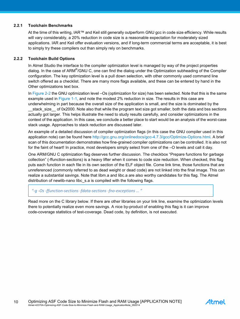
2.2.1 Toolchain Benchmarks At the time of this writing, IAR™ and Keil still generally outperform GNU gcc in code size efficiency. While results will vary considerably, a 20% reduction in code size is a reasonable expectation for moderately sized applications. IAR and Keil offer evaluation versions, and if long-term commercial terms are acceptable, it is best to simply try these compilers out than simply rely on benchmarks.
2.2.2 Toolchain Build Options In Atmel Studio the interface to the compiler optimization level is managed by way of the project properties dialog. In the case of ARM®/GNU C, one can find the dialog under the Optimization subheading of the Compiler configuration. The key optimization level is a pull down selection, with other commonly used command line switch offered as a checklist. There are many more flags available, and these can be entered by hand in the Other optimizations text box.
In Figure 2-2 the GNU optimization level –Os (optimization for size) has been selected. Note that this is the same example used in Figure 1-1, and note the modest 2% reduction in size. The results in this case are underwhelming in part because the overall size of the application is small, and the size is dominated by the __stack_size__ of 0x2000. Note also that while the program text size got smaller, both the data and bss sections actually got larger. This helps illustrate the need to study results carefully, and consider optimizations in the context of the application. In this case, we conclude a better place to start would be an analysis of the worst-case stack usage. Approaches to stack reduction are discussed later.
An example of a detailed discussion of compiler optimization flags (in this case the GNU compiler used in this application note) can be found here http://gcc.gnu.org/onlinedocs/gcc-4.7.3/gcc/Optimize-Options.html. A brief scan of this documentation demonstrates how fine-grained compiler optimizations can be controlled. It is also not for the faint of heart! In practice, most developers simply select from one of the –O levels and call it day.
One ARM/GNU C optimization flag deserves further discussion. The checkbox “Prepare functions for garbage collection” (-ffunction-sections) is a heavy lifter when it comes to code size reduction. When checked, this flag puts each function in each file in its own section of the ELF object file. Come link time, those functions that are unreferenced (commonly referred to as dead weight or dead code) are not linked into the final image. This can realize a substantial savings. Note that libm.a and libc.a are also worthy candidates for this flag. The Atmel distribution of newlib-nano libc_s.a is compiled with the following flags.
Read more on the C library below. If there are other libraries on your link line, examine the optimization levels there to potentially realize even more savings. A nice by-product of enabling this flag is it can improve code-coverage statistics of test-coverage. Dead code, by definition, is not executed.
“-g -Os -ffunction-sections -fdata-sections -fno-exceptions … ”

Optimizing ASF Code Size to Minimize Flash and RAM Usage [APPLICATION NOTE] Atmel-42370A-Optimizing-ASF-Code-Size-to-Minimize-Flash-and-RAM-Usage_ApplicationNote_092014
11
Figure 2-2. Atmel Studio Optimization Level Selection of GNU –Os
2.2.3 Embedded C Library Selection In the case of AVR®, the supplied C Library was designed and built from the onset with compactness in mind. There are few competing C Library implementations that offer the robustness or scalability. It’s essentially the only game in town. Refer to the sections on stdio carefully, and utilize the pragmas to put data, especially strings, into the program section of your application. Use it with confidence that it will not contribute to your application size unless it is referenced incorrectly.
The same cannot be said about ARM C Library. First of all it comes in two flavors – libc.a (newlib) and libc_s.a (newlib-nano). For those who seek a C Library with all the trimmings, newlib is for you. For those who seek an implementation of printf() without all the bloated formatting options (especially nice is the weak symbol reference to floating point which avoids dragging in floating point emulation support), and for those who don’t need wide char support, or over-complicated heap management, newlib-nano is for you.
For example a simple application that invokes printf (“Hello World!\n”) can be reduced by 80%!
By default, Atmel Studio ARM based projects do not specify which C library to reference, and most programmers, by force of habit, use –lc on the linker line. Try –lc_s next time!
It is also advisable to limit use of streamed I/O or iov buffering. In the absence of a proper I/O system, these functions can take up a surprising amount of space. There are also reentrancy issues when used in the context of FreeRTOS (or any RTOS), that newlib-nano does not handle as robustly as newlib (or a complete embedded RTOS). So if you must use buffered I/O via libc_s.a, do so from a single thread.

Optimizing ASF Code Size to Minimize Flash and RAM Usage [APPLICATION NOTE] Atmel-42370A-Optimizing-ASF-Code-Size-to-Minimize-Flash-and-RAM-Usage_ApplicationNote_092014
12
3 Reducing Application Flash Requirements If optimizing application size by tuning the tools is not sufficient, we must turn to the code itself. The amount of text (program space) is summarized in the output window at the completion of an Atmel Studio build. Put simply, something has to go. How do we decide what features to cut? How do we know with confidence that no superfluous code has crept into our build image? In this section we consider these questions and propose approaches to reduce an application’s flash requirements.
3.1 ASF Wizard Component Removal ASF is organized as a collection of software components. These components can be drivers, services, or even third party middleware. All of the source code associated with these components is kept in the Atmel Studio installation directory. Embedded in this tree are component descriptor files that use XML (Extensible Markup Language) to describe the meta-data of each of the components. The meta-data includes the manifest of files that make up the component, and also any other ASF components that are depended upon. Tracking these inter-component dependencies allows the Atmel Studio ASF Wizard to copy out all of the necessary files into a new ASF based project. Any given project is simply a copied subset of the ASF tree of files that are relevant to the selected configuration.
This collection of XML files can be thought of as a database of ASF content. Studying the XML to trace component dependencies can be time consuming but thankfully Atmel Studio makes this process straightforward. The best way to browse the dependency graph is to work with the Atmel Studio ASF Wizard. Refer to Figure 3-1.
Figure 3-1. ASF Component Browsing with the Atmel Studio ASF Wizard

Optimizing ASF Code Size to Minimize Flash and RAM Usage [APPLICATION NOTE] Atmel-42370A-Optimizing-ASF-Code-Size-to-Minimize-Flash-and-RAM-Usage_ApplicationNote_092014
13
Note that each component’s dependencies are enumerated as sub-components. In this case, the OLED controller is SPI based and therefore one of the dependencies is the SERCOM SPI driver. One can browse these interdependencies by simply expanding the components hierarchical tree. By building a project up component-by-component, and keeping track of the size of the builds, the relative weight of the features can be tallied and evaluated. This represents the first step of deciding what functionality will fit, and which configuration best suits the application.
It is important to not to confuse the functionality of the ASF Wizard with that of the toolchain. The ASF Wizard does not look at the code itself, or the symbolic inter-dependencies. It dutifully copies the manifest of each component into the Atmel Studio project folder, and provisions the build environment. When built, the compiler and loader will optimize out any unused functions (when configured as previously discussed), and will otherwise optimize the code.
Code size reductions beyond this point will require changes to the code itself. In so far as the project is a copy of ASF components, code changes there are isolated from the released components. One can experiment, and revert back to the original release by use of the ASF Wizard. Be careful, however, to avoid overwriting local project changes with original ASF components by way of the ASF Wizard if any changes have been made.
3.2 Dependency Tracing and Scaling out Functionality Despite the fact that ASF provides all of the source code that is associated with a project, it is not always obvious what functionality, post toolchain build time optimizations, actually ended up in the final binary. It is also useful to get a sense of the size of each of the resulting modules.
There are two tools that are part of the ARM/GNU gcc toolchain which help study the contents of the final binary. The first tool is actually a file that is created during every build. One of the output files of Atmel Studio is a load map by way of the following flag during the final linking stage.
It is well worth the time to master the details contained in the load map file. A full tutorial on the contents of the load map is beyond the scope of this application note since the information is better described in the GNU manual for ld. Suffice it to say that this map summarizes the memory mappings, sizes, and virtually all of the details associated with the build image. It is a roadmap to optimization opportunities.
While the load map file provides us information of what we are, the second tool, GNU nm helps us figure out how we got there! This toolchain utility routine can be used to study interdependencies of files and even arbitrary combinations of files. There are a number of useful command line flags to nm, but here are the most important for our purposes. % man nm -g,--extern-only
Display only external symbols. -n,-v,--numeric-sort
Sort symbols numerically by their addresses, rather than alphabetically by their names.
-u,--undefined-only
Display only undefined symbols (those external to each object file). --defined-only
Display only defined symbols for each object file.
-Wl,-Map="USART_QUICK_START_CALLBACK1.map"

Optimizing ASF Code Size to Minimize Flash and RAM Usage [APPLICATION NOTE] Atmel-42370A-Optimizing-ASF-Code-Size-to-Minimize-Flash-and-RAM-Usage_ApplicationNote_092014
14
By studying the undefined symbols in object files, one can quickly ascertain what causes certain modules to drag in unexpected functionality. Once an unexpected symbolic reference is isolated, a quick reference back to the associated source code will help explain the reason. This technique is particularly powerful if you combine it with incremental linking or partial linking.
Incremental linking is a technique of combining a collection of relocatable object files into one single relocatable object file that can in turn serve as input to ld. In other words, all resolvable symbolic interdependencies between the object modules of the collection are linked, and only undefined symbols that refer to object files outside of the collection remain. The chosen collection of object files is arbitrary, but in practice one partition these collections of object files into known blobs of functionality (e.g. an ASF component that is made up of more than one file). The steps necessary to incrementally link a collection of object files and find remaining dependencies is as follows.
A series of experiments with various combinations of partially linked object modules, and a careful study of the load map will provide insight into where an undesired module was referenced. Once established at the symbolic level, utilize Atmel Studio Visual Assist feature to study the dependency at the source code level.
As before, this approach can be used to incrementally remove (tear down) an application by attempting to jettison unwanted modules. Alternatively, this approach can be used to incrementally add (build up) and application with must-have features. Either way, you may find surprises, and uncover source code interdependencies that are the root cause to the over-sized application. What next?
3.3 Simplifying Code In the previous section we performed a forensic analysis on the build image. We have the insight on possible code changes to simplify the application. Here are some possibilities.
Constant data is allocated to the flash memory in the interest of conserving RAM. In some cases, there can actually be too much constant data stored in this way. If there is RAM still available, consider changing the code to put constant data back in volatile storage. It is not advised to simply remove the keyword “const” as there would be a loss of information to the compiler (and warnings of bugs to the programmer!). Refer to your toolchain documentation for mechanisms to manage the location of constant data.
Many ASF drivers are written for a wide range of modes to be supported and changed during runtime. The initialization of the driver is parametric by way of an initialization structure. There are pros and cons of this approach. A high degree of runtime configurability, improves portability, and code readability, but this generality comes at the expense of code size. In situations where an application has a known static configuration of a driver in mind, it is quite common to simplify the initialization of the driver to provide a fixed functionality. Consider the ASF SERCOM USART configuration structure and USART initialization in the following code fragment. /* Set default config in the config struct */ config->data_order = USART_DATAORDER_LSB; config->transfer_mode = USART_TRANSFER_ASYNCHRONOUSLY; config->parity = USART_PARITY_NONE; config->stopbits = USART_STOPBITS_1; config->character_size = USART_CHARACTER_SIZE_8BIT; config->baudrate = 9600; config->receiver_enable = true; config->transmitter_enable = true; config->clock_polarity_inverted = false;
../arm-none-eabi-ld.exe –o result.o –r one.o two.o three.o
../arm-none-eabi-nm.exe –u result.o

Optimizing ASF Code Size to Minimize Flash and RAM Usage [APPLICATION NOTE] Atmel-42370A-Optimizing-ASF-Code-Size-to-Minimize-Flash-and-RAM-Usage_ApplicationNote_092014
15
config->use_external_clock = false; config->ext_clock_freq = 0; config->mux_setting = USART_RX_1_TX_2_XCK_3; config->run_in_standby = false; config->generator_source = GCLK_GENERATOR_0; config->pinmux_pad0 = PINMUX_DEFAULT; config->pinmux_pad1 = PINMUX_DEFAULT; config->pinmux_pad2 = PINMUX_DEFAULT; config->pinmux_pad3 = PINMUX_DEFAULT; /* Now initialize usart */ usart_init(&usart_instance, SERCOM3, config);
While the details of this configuration here are not important, there are sizing issues to consider. Clearly this configuration structure allows for a high-degree of runtime configurability. The config structure alone takes up 48 bytes. At the expense of generality, the initialization can be simplified by rewriting usart_init to hard wire particular modes of operation, and the corresponding fields in the initialization structure can be removed. In the case of the D20 SERCOM USART driver in callback mode, a simplification on the order of 1K bytes is attainable.
Another straightforward simplification can be applied to the ASF pinmux support. ASF is written to support a fully re-configurable range of mappings of microcontroller pins to the selected pin functionality. This is so an example can easily be retargeted to a wide range of custom configurations. In a final product design, the pin allocation is fully specified. As with usart_init, it is possible to hard wire the assignment of pin functionality, and realize significant savings.
3.4 Example Putting the techniques summarized above here are some example results when downsizing a simple ASF application on the Atmel SAMD20 using an ADC and USART. This example did not reduce the stack size from the default of 0x2000. In this exercise, callback support for the ADC was removed, the optimization level was increased, newlib-nano was utilized, polled versions of the drivers selected, the IAR compiler was selected, and ultimately the initialization routines were simplified. Application: ASF example with ADC and USART drivers Atmel Studio, Optimization -O1 no nanolib, callback support enabled (standard configuration): Program Memory Usage : 10000 bytes Data Memory Usage : 9392 bytes Atmel Studio, Optimization -Os, nanolib, polled ADC and USART driver: Program Memory Usage : 7532 bytes Data Memory Usage : 8280 bytes IAR, With max optimization for size, polled ADC and USART driver: readonly code memory : 4548 bytes readonly data memory : 208 bytes readwrite data memory : 8276 bytes IAR, Cutting out all adc_init and usart_init code except pinmux code and clock setup readonly code memory : 2788 bytes readonly data memory : 208 bytes readwrite data memory : 8276 bytes Some function optimizations remain, error handling could be disabled, but this is sufficient.

Optimizing ASF Code Size to Minimize Flash and RAM Usage [APPLICATION NOTE] Atmel-42370A-Optimizing-ASF-Code-Size-to-Minimize-Flash-and-RAM-Usage_ApplicationNote_092014
16
4 Reducing Application RAM Requirements In some cases the application fits comfortably in available flash memory, but there is not enough RAM to support the read/write data. Here are some approaches.
4.1 Data Segment and Constant Data Review the material concerning the load map, ld, and nm covered in the previous section as these tools apply to this examination as well. Note that listing the data symbols in numeric order (as opposed to the symbolic name order) will allow you to determine the heaviest data structures in your application. Some versions of nm even perform this numeric calculation for you.
Can some of this data be declared read-only? If so, and there is still room in flash, reassign it. Can some of the heavier data structures be subsetted into constant and volatile portions? Are some of the arrays oversized by default? And so forth.
Often data structures grow unnecessarily large when migrated from an 8-bit to a 32-bit architecture. Are the integers really 32 bits in length? Can they be reduced in size with one of the standard ANSI C types (stdtype.h)? Can you use bit packing of Boolean values, or sub-eight bit fields?
All of these questions must be evaluated with long-term re-use, portability, and readability in mind. Smaller is not always desirable, if the maintenance and up-keep of the code suffers because of it.
4.2 Stack Allocation Tuning Establishing the correct stack size can be a challenge. Without rigorous code analysis (or a static analysis tool) the maximum routine call depth of even a modestly complex application is not easy to ascertain. Many calls happen conditionally based upon data available at runtime. Full simulations are not always practical.
One common technique is to fill the stack with a known byte pattern (e.g. 0xee), and then after some reasonable duration of real-world execution the stack is examined to establish a high water mark. The high water mark denotes the highest (or lowest) memory location reached on the stack by seeing what portion of the stack was left unchanged. This approach is certainly fallible. How long is reasonable duration? It is possible to pass a struct as a parameter to a routine, and if this struct is not modified (or partially modified), it may look as if the stack pointer was lower than it actually reached. With a factor of safety added, this approach is reasonable.
Another approach is to periodically sample the stack pointer in an asynchronous interrupt. Over some statistically conservative period of time, the high water mark of the stack pointer can be established. The principle challenge in this approach is achieving a truly random sample, and for this sampling process to not disrupt the correct functionality of the application.
Finally there is a trial and error approach in which the stack size is reduced until the application fails, and then increased a bit. This is not advised. Stack crashes can be extremely difficult to diagnose, and they almost always happen at the worst possible time (e.g. after a product ships). It also leaves the application in a fragile configuration where the smallest change (bugfix), might destabilize the application in bizarre and unexpected ways.
4.3 Preemptive vs. Cooperative Scheduling Many microcontroller-based applications now rely upon a RTOS to provide preemptive scheduling of tasks (or threads) of execution. FreeRTOS is integrated and available for use with ASF based applications. An RTOS provides an excellent framework to enable independent application features to be developed in isolation to one-another, while still coordinating their temporal behavior. Real-time applications can be more deterministic, scalable, and portable than applications that are purely event driven or polled.
A cost to utilizing preemption is that a copy of each thread’s state needs to be preserved during the time it is not scheduled to run. This not only includes the microcontroller register values, but it also includes a per-thread stack

Optimizing ASF Code Size to Minimize Flash and RAM Usage [APPLICATION NOTE] Atmel-42370A-Optimizing-ASF-Code-Size-to-Minimize-Flash-and-RAM-Usage_ApplicationNote_092014
17
allocation. In practice the stack-per-thread allocation of RAM can really add up quickly, and can limit the number of threads one can execute concurrently on a microcontroller.
As was discussed in the previous section, correctly sizing the stack is important. In this case our problem multiplied since we need to determine the appropriate stack size for each thread! A common technique is to use an idle task, at the lowest priority, to sample the high water marks of every other tasks stack and report an exception if a stack is ever exhausted.
In the context of this application note, reducing the size of a FreeRTOS ASF application follows the same overall approach, but with additional areas of focus. Start by justifying the need for each and every thread. If a thread can be eliminated, it will realize considerable RAM savings. Work hard on getting the stacks correctly sized. Make sure that interrupt service routines do not have additional subroutine calls because every task could be interrupted, and thus every task has to have at least enough spare stack space for the deepest nested interrupt call. Recall that interrupts can also nest.
After exhausting all possible reductions in memory usage of a multi-threaded application, one could consider adopting a cooperative scheduler. A cooperative scheduler keeps a queue of prioritized tasks (e.g. a protothread in Contiki), and dispatches them on a priority basis when the kernel is called from another thread. A cooperative scheduler never preempts another thread so there is no need to carry around the extra overhead of a thread’s context (the register set and a private stack). All threads are dependent upon each other to finish their tasks in a timely manner and return control to the kernel to dispatch the next task. It is in this sense that the scheduler is referred to as cooperative.
While there are some publicly available cooperative schedulers, most embedded engineers develop an application specific implementation. The most common implementation is a foreground/background scheduler in which time critical functions are dispatch to a foreground task, and when idle, housekeeping activities are managed by a background task. While rudimentary from a multi-tasking perspective, cooperative scheduling does offer some of the RTOS advantages of application partitioning and decomposition without as much baggage.

Optimizing ASF Code Size to Minimize Flash and RAM Usage [APPLICATION NOTE] Atmel-42370A-Optimizing-ASF-Code-Size-to-Minimize-Flash-and-RAM-Usage_ApplicationNote_092014
18
5 Revision History Doc Rev. Date Comments
42370A 09/2014 Initial document release.

Optimizing ASF Code Size to Minimize Flash and RAM Usage [APPLICATION NOTE] Atmel-42370A-Optimizing-ASF-Code-Size-to-Minimize-Flash-and-RAM-Usage_ApplicationNote_092014
19
Atmel Corporation 1600 Technology Drive, San Jose, CA 95110 USA T: (+1)(408) 441.0311 F: (+1)(408) 436.4200 │ www.atmel.com © 2014 Atmel Corporation. / Rev.:Atmel-42370A-Optimizing-ASF-Code-Size-to-Minimize-Flash-and-RAM-Usage_ApplicationNote_092014. Atmel®, Atmel logo and combinations thereof, AVR®, Enabling Unlimited Possibilities®, and others are registered trademarks or trademarks of Atmel Corporation in U.S. and other countries. ARM®, ARM Connected® logo, and others are the registered trademarks or trademarks of ARM Ltd. Other terms and product names may be trademarks of others. DISCLAIMER: The information in this document is provided in connection with Atmel products. No license, express or implied, by estoppel or otherwise, to any intellectual property right is granted by this document or in connection with the sale of Atmel products. EXCEPT AS SET FORTH IN THE ATMEL TERMS AND CONDITIONS OF SALES LOCATED ON THE ATMEL WEBSITE, ATMEL ASSUMES NO LIABILITY WHATSOEVER AND DISCLAIMS ANY EXPRESS, IMPLIED OR STATUTORY WARRANTY RELATING TO ITS PRODUCTS INCLUDING, BUT NOT LIMITED TO, THE IMPLIED WARRANTY OF MERCHANTABILITY, FITNESS FOR A PARTICULAR PURPOSE, OR NON-INFRINGEMENT. IN NO EVENT SHALL ATMEL BE LIABLE FOR ANY DIRECT, INDIRECT, CONSEQUENTIAL, PUNITIVE, SPECIAL OR INCIDENTAL DAMAGES (INCLUDING, WITHOUT LIMITATION, DAMAGES FOR LOSS AND PROFITS, BUSINESS INTERRUPTION, OR LOSS OF INFORMATION) ARISING OUT OF THE USE OR INABILITY TO USE THIS DOCUMENT, EVEN IF ATMEL HAS BEEN ADVISED OF THE POSSIBILITY OF SUCH DAMAGES. Atmel makes no representations or warranties with respect to the accuracy or completeness of the contents of this document and reserves the right to make changes to specifications and products descriptions at any time without notice. Atmel does not make any commitment to update the information contained herein. Unless specifically provided otherwise, Atmel products are not suitable for, and shall not be used in, automotive applications. Atmel products are not intended, authorized, or warranted for use as components in applications intended to support or sustain life.
SAFETY-CRITICAL, MILITARY, AND AUTOMOTIVE APPLICATIONS DISCLAIMER: Atmel products are not designed for and will not be used in connection with any applications where the failure of such products would reasonably be expected to result in significant personal injury or death (“Safety-Critical Applications”) without an Atmel officer's specific written consent. Safety-Critical Applications include, without limitation, life support devices and systems, equipment or systems for the operation of nuclear facilities and weapons systems. Atmel products are not designed nor intended for use in military or aerospace applications or environments unless specifically designated by Atmel as military-grade. Atmel products are not designed nor intended for use in automotive applications unless specifically designated by Atmel as automotive-grade.