optimizing rfid reader settings for increased performance
TRANSCRIPT


Hal Endressen • Intermec Technologies
EPCC1G2 Optimized

Part 1
• General Update
• EPCC1G2 Commands
Agenda Part 2
• Optimizing Readers
• RFID FAQ

• RFID Die Terminology
• Reader Interface Update
• BRI Attribute Update
General Update

RFID Dies Terminology
• G1• Made by Fairchild• ISO 6B• No longer in production
• G2• Made by Philips• ISO 6B• EPC 1.19
• EPCC1G2• Various manufacturers• EPC Class 1 Gen 2

Reader Interface Update
• Firmware 2.xx (Current)• Can read ISO 6B tags (G1, G2 die)• API interface (T6, .NET)• BRI interface
• Firmware 3.xx (not yet released)• EPCC1G2 enabled firmware• Can read G1, G2, and EPCC1G2 die• BRI interface only• Beta version available

IF5 Release 2 Update
• BRIdge in release 1 has been replaced with the Data Collection Engine (DCE)
• The DCE will block the following attributes from being changed
• TTY• ECHO• BAUD• CHKSUM• FACDFLT• RESET

IF5 Release 2 Update
• DCE Default Values• TTY = OFF• ECHO = OFF• BAUD = 115200• CHKSUM = OFF

IF5 Release 2 Update
• If you open the IF5 box and connect directly to the RF module, you will find that the DCE has enabled CHKSUM on the RF module.
• However if you send “attrib chksum” to the IF5, it will tell you that CHKSUM=OFF

IF5 Release 2 Update
• TIMEOUT Message• If the DCE does not receive a response from
the RF module in approximately 10 minutes after a command has been sent, it will respond with a TIMEOUT message
• The DCE watches for the OK> response from the RF module

IF5 Release 2 Update
• BUSY Message• The DCE will respond with a BUSY
message if you try to send a command while another command is still in process

BRI Attribute Update
• Updated attributes• TAGTYPE
• New attributes valid for firmware versions 3.xx• IDTIMEOUT• ANTTIMEOUT• INITIALQ• SESSION• Please note a more detailed description of the use of
these attributes will follow this section• There will be further additions in future releases

Attribute TAGTYPE
• Current valid values• G1• G2• Mixed (used for both G1 and G2 die but not
EPCC1G2 die)• Added the following values for firmware 3.xx
• EPCC1G2• ICODE119• For mixed tag populations use
• TAGTYPE = G2,EPCC1G2,…etc.• Only reads G2 and EPCC1G2 tags but not G1 and
ICODE tags

Attribute IDTIMEOUT
• Can be used in place of IDTRIES• Follows same rules as IDTRIES
• Except IDTRIES valid range 1-255• Sets the amount of time the reader
should look for tags per antenna• Valid range is 0 to 65,535 milliseconds• May use either timeouts or tries but not
both

Attribute ANTTIMEOUT
• Can be used in place of ANTTRIES• Follows same rules as ANTTRIES
• Except ANTTRIES valid range 1-255
• Used to select the antenna operation mode for the reader (will be addressed in more detail later)
• Valid range is 0 to 65,535 milliseconds• May use either timeouts or tries but not both

Attribute INITIALQ
• Used only for EPCC1G2 tags• Sets the initial seed for the tags random
number generator• Ideally, the number of tags you are reading
should equal two to the power of initialq• num tags = 2^initialq • Once the reader detects a collision between tags, it
will automatically increase the Q value• Valid range is 0 to 15• Use initialq = 0 for reading single tags• Use initialq = 4 for reading multiple tags

Sessions for EPCC1G2
• There are 4 sessions available• SESSION = 0• SESSION = 1• SESSION = 2 (default session)• SESSION = 3
• Each session has an Inventory Flag (bit) that gets set during the READ command
• The Inventory Flag is set once the tag transmits its EPC code
• The amount of time the Inventory Flag remains set, even if the tag loses power, is called PERSISTANCE
• Similar to the Philips G2 die super bit
Sessions for EPCC1G2
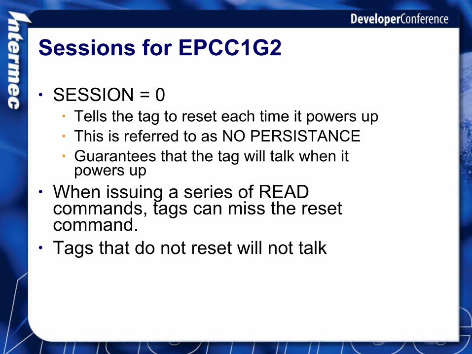
• SESSION = 0• Tells the tag to reset each time it powers up• This is referred to as NO PERSISTANCE• Guarantees that the tag will talk when it
powers up• When issuing a series of READ
commands, tags can miss the reset command.
• Tags that do not reset will not talk

Sessions for EPCC1G2
• SESSION = 0 is not good for reading numerous tags at once because if a tag loses power momentarily, it will reset and participate in the anti-collision algorithm again

Sessions for EPCC1G2
• SESSION = 1• Tells the tag to remember that is has talked even
when it loses power.• Tag persistance will lasts a maximum time of 5
seconds whether it has power or no power• Even if the tag remains powered, it will reset after a
maximum time of 5 seconds• Tag will reset when it sees the next READ command
assuming it does not miss the reset command

Sessions for EPCC1G2
• SESSION = 2 or 3• Tells the tag to remember that is has talked
even when it loses power.• Tag persistance lasts at least 2 seconds• The maximum persistance time is up to
each manufacturer of die• Tag will reset when it sees the next READ
command assuming it does not miss the reset command

Sessions for EPCC1G2
• SESSION = 2 or 3 can be used for any number of tags in the field
• When only one tag is present, it should not affect it’s read time

Attribute FIELDSTRENGTH
• FIELDSTRENGTH=100,100,100,100• Sets the power level for each antenna• Valid range 0-100 (% Max Power)• Active in 3.xx firmware• For best results (accurate) reader must be
calibrated by Intermec• If you find any of the values set to 255, make
sure you set them to 100 or the reader may not turn on that antenna
Upgrading Existing IM5 Readers
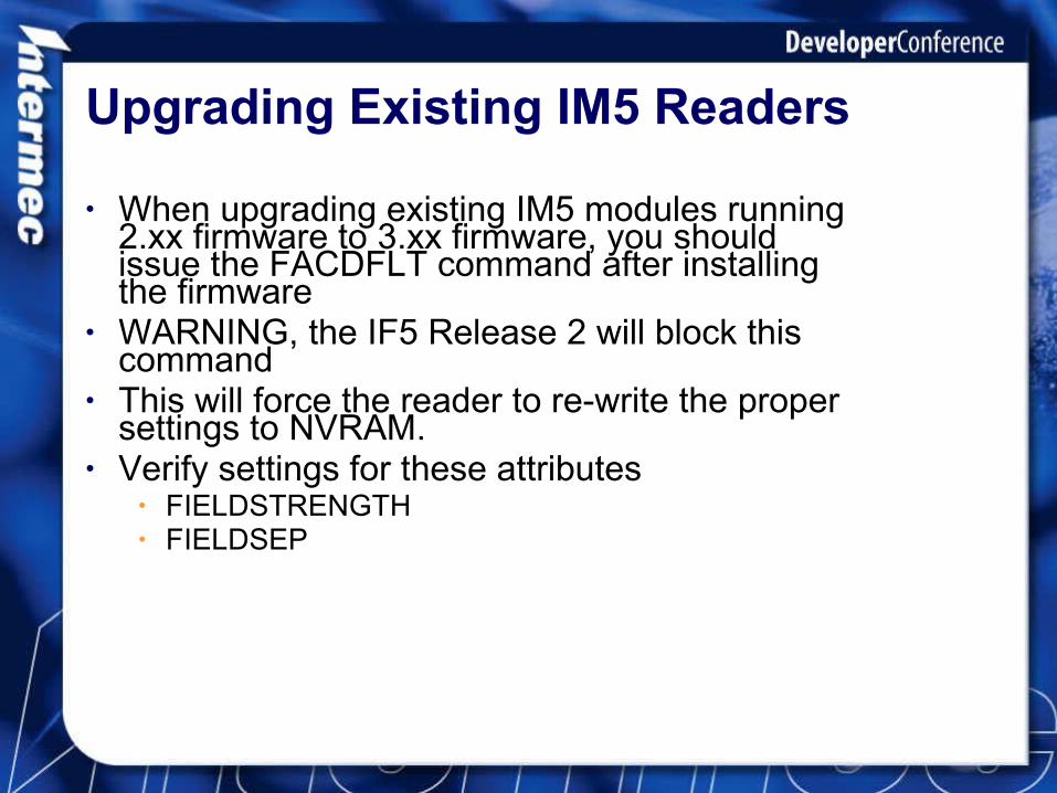
• When upgrading existing IM5 modules running 2.xx firmware to 3.xx firmware, you should issue the FACDFLT command after installing the firmware
• WARNING, the IF5 Release 2 will block this command
• This will force the reader to re-write the proper settings to NVRAM.
• Verify settings for these attributes• FIELDSTRENGTH• FIELDSEP

• Reading EPCC1G2 Die
• Writing EPCC1G2 Die
EPCC1G2 Commands

Reading EPCC1G2 Tags
• Set ATTRIBUTE TAGTYPE=EPCC1G2• Send the READ command (or R, RD)• Do NOT waste time sending
• Read EPCID• Read TAGID
• Reader will return the 12 byte EPC code• EPC Code is stored in memory bank 1, bytes
4-15• Byte 2 is the EPC code length • Byte 4 is the EPC header

Reading EPC Memory Banks
• Read Hex(Bank:Start Addr,Length)• Valid Memory banks are 0 to 3
• Bank 0 is passwords• Bank 1 is EPC• Bank 2 is TID• Bank 3 is user memory (optional)
• Start address can be any value 0 to X• Length can be any value 1 to Max Length• Note the colon (:) between Memory Bank
and Start Address

Writing EPC Memory Banks
• Write EPCID=xxxxxx (24 hex nibbles)• No other parameters required
• Write Hex(Bank:Start Addr,Length)• Start address must be even (0,2,4…)• Warning EPC Tags require a minimum write
length of 2 bytes• If you write only one byte say to byte 3, the
tag will write a null (0x00) to byte 2!• Length can be any even value 2 to Max
Length

Part II
Optimizing Reader Performance
• The Problem
• Antenna Control
• Making the reader do the work

Key to Reading Tags
• Make sure you cycle thru your antennas efficiently
• Antenna control mode• Make the reader do the work not your
application• Uses appropriate attribute settings
• Avoid resetting the tags during the read process
• Every READ command resets the tags• When tags lose power they reset

The Problem with Moving Tags
• Most RFID scenarios involve tags moving past the antennas.
• There is limited amount of time to read all of the tags
• You do not want to spend too much time on any one antenna or you will miss tags on the other antennas

Problem Is Always There
• Does not matter if you have one tag randomly located on a pallet or 30 tags spread out all over a pallet
• If the reader wastes too much time on one antenna looking for tags, you may miss the tag(s)
• It is best to make sure the reader switches antennas as soon as it is no longer finding new tags

Why Me???
• As a developer why is this my concern?• How do I do this?

Avoid the Crash and Burn
• For the entire system of readers, tags, and antennas to work properly, the application must be responsible for configuring and controlling the reader for optimal operation
• Each application will require different software settings for optimization

Antenna Control

Antenna Control Methods
• Reader has two methods of controlling the antennas
• Method can be selected by the user by the values assigned to IDTRIES and ANTTRIES or IDTIMEOUT AND ANTTIMEOUT
• EPCC1G2 tags have further options• Attribute InitialQ• Attribute SESSION

Method One
• Execute all tries/time on an antenna before switching to the next antenna
• Activate by setting ANTTRIES>IDTRIES• ANTTRIES=20• IDTRIES=15• ANTTRIES functions solely as a flag• Reader will execute 15 tries per antenna• Reader will execute 15 tries on antenna one
and then cycle to antenna 2, etc.

Example Method 1: TIMEOUTS
• IDTimeout=4000• AntTimeout=100• The reader tries to find tags for a total of 4
seconds.• If at any time the reader does not see any new
tags for continuous period of 100 milliseconds, it will switch to the next antenna.
• It is possible that the reader will not cycle thru all of the antennas

Example Method 1: TIMEOUTS
Antenna 1
First 300 milliseconds
Next 100 milliseconds
Switch to antenna 2

Example Method 1: TIMEOUTS
Antenna 2
Next 1500 milliseconds
Next 100 milliseconds
Switch back to antenna 1
Next 100 milliseconds
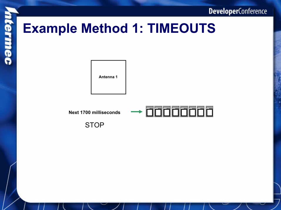
Example Method 1: TIMEOUTS
Antenna 1
Next 1700 milliseconds
STOP

Example Method 1: TRIES
• IDTRIES=5• ANTTTRIES=3• The reader tries 5 times per antenna to find
tags• If at any time the reader does not see any new
tags for 3 consecutive tries, it will switch to the next antenna.
• It will continue to cycle thru antennas until it has completed 5 tries on each antenna

Example Method 1: TRIES
Antenna 1
Try 1
Try 2
Try 3
Try 4
Switch to antenna 2 now

Example Method 1: TRIES
Antenna 2
Try 1
Try 2
Try 3
Try 5
Try 4
Switch back to antenna 1

Example Method 1: TRIES
Antenna 1
Try 5
STOP

Method Two
• Switch antennas after X tries in a row without any new tags
• Activate by setting ANTTRIES<IDTRIES• ANTTRIES=3• IDTRIES=10• ANTTRIES is the number of tries without
any new tags being found

Example Method 2: TIMEOUTS
• IDTIMEOUT = 4000• ANTTIMEOUT=6000• The reader tries for 4 seconds per
antenna to find tags• The reader will switch antennas after the
4 second interval

Example Method 2: TIMEOUTS
Antenna 1
Continuously try to read tags for 4 seconds
Antenna 2
Switch to antenna 2 now
Continuously try to read tags for 4 seconds then
STOP

Example Method 2: TRIES
• IDTRIES = 5• ANTTRIES=6• The reader tries 4 times per antenna to
find tags• The reader will switch antennas only
after it has completed all 4 tries

Example Method 2: TRIES
Antenna 1
Try 1
Try 2
Try 3
Try 5
Try 4
Antenna 2
Try 1
Try 2
Try 3
Try 5
Try 4
Switch to antenna 2 now

What’s a TRY Anyhow?
• A TRY refers to an execution of the anti-collision algorithm
• May result in any number or tags being found or none at all
• ISO and EPCC1G2 have very different anti-collision algorithms
• What the heck is an anti-collision algorithm?

What’s An Anti-Collision Algorithm?
• It is the method the reader uses to talk to multiple tags
• EPCC1G2 algorithm is based on the tags rolling a many sided die to determine talking order
• The attribute InitialQ tells the tags how many sides the dice has. This value will be changed as the reader detects collisions (2 or more tags talking at the same time)

EPCC1G2 Anti-Collision Algorithm
• Tags roll a 2^Q sided die• Tags that roll a zero generate another
random number of size 2 bytes and transmit that number to the reader (this is the tags temporary handle)
• If a collision occurs, the tags are told to roll again but this time the reader will increase the size of Q

EPCC1G2 Anti-Collision Algorithm
• If after rolling the dice, no tags has a value of zero (no tags respond to the reader), then the reader asks all tags to subtract one from their random number
• Any tag that is now at zero responds.• Reader keeps asking tags to subtract
one.

The ISO Exchange
• ISO Tags send their 8 byte ID• The reader then requests another 8 bytes from
the tag (bytes 10-17) using the 8 byte ID• Guarantees that the tag exists and that the ID
is valid• A total of 24 bytes of data have to be
transmitted between tag and reader, not counting the RF commands
• Reader will now use the 8 byte ID for all read and write commands for this tag

The EPCC1G2 Exchange
• EPCC1G2 Tags generate a random number handle (size 2 bytes) and transmit it to the reader
• The reader then requests the EPC code (12 bytes) using that random number handle
• Guarantees that the tag exists and that the EPC code is valid
• A total of 16 bytes are exchanged between the reader and tag, not counting the RF commands

The EPCC1G2 Exchange
• If the user had sent one of these commands:• R hex(2:6,8)• W hex(2:4,4)=h01020304• The reader will run the anti-collision algorithm to find
all tags BUT…• After receiving the EPC code, the reader will ask the
tag (using the random number handle) to generate a new random number handle.
• This new handle will be used for the read (or write) of the memory bank

The EPCC1G2 Exchange
• Unlike ISO, the reader must always start with a general identify of all tags in the field before it can read or write a memory bank, EVEN if you already know the EPC code of the tag you want to read or write.

The EPCC1G2 Exchange
• Tags can only be isolated by adding a filter to the command
• R hex(2:4,3) where hex(1:4,2)=h0102
• All tags matching that value will be read or written to.
• You can filter on any byte(s) in memory banks 1,2, and 3

• InitialQ
• SESSION
• IDTRIES…
Making The Reader Do The Work

Reading One EPCC1G2 Tag
• Use SESSION=0 or 2• Set InitialQ=0• Tells the tag(s) to talk immediately• Fastest method for reading an EPC code• If more than one tag is present the reader will
see collisions.• Bad for cases with more than one tag present

Reading Multiple EPCC1G2 Tags
• Best to use SESSION=2 or 3• Set InitialQ=4• Tells the tag(s) to roll a 2^4 sided dice
• Range 0 to 15• Can be used for single tags but takes
longer to execute• Reader will automatically increase this
value when it sees collisions

How Big Should InitialQ Be?
• In limited testing I have not seen a performance improvement setting InitialQ higher than 4.
• However I encourage you to experiment and see what happens

The Read Command
• The READ command actually tells the reader to run the anti-collision algorithm
• It begins by powering up the tags and sending out a RESET command to all tags
• Tags will talk after resetting• Important when using SESSION 1-3• Tags that miss the reset command and have
the session bit (1-3) set will NOT talk

The Read Command
• Resetting Tags• Tags will automatically reset if they have lost
power for an extended time period no matter what session is selected
• A reset command (INITTRIES) at the start of each READ command will reset all tags that hear it

The Read Command
• When trying to read a large number of tags, you do not want the tags to reset
• To avoid resetting tags, send one read command but with its IDTimeout/IDTries set to a large number
• In testing, where tags are repeatedly run past the reader, you may find that the some tags may miss the reset command and so the persistance flag will not get reset
• This will prevent that tag from being read
FAQ EPCC1G2 Questions

Inventory Flag A & B
• Tag uses this flag internally. Toggles from A to B when it has sent its EPC code
• Initial state is always A• Set on to A on power up of tag• Do users have access to this flag?
• No
• Can I use these flags for performance improvements?
• No.

What is the EPCISO Bit?
• This bit is an identifier indicating if the tag has an EPC code or ISO ID in the EPC memory bank (1)
• Located in memory bank 1, byte 4• The BRI in release A will not use this bit

Will T6 have EPCC1G2 functionality?
• No. The T6 API will not be updated to handle EPCC1G2 tags.
• Thought the API is not being put to rest, it is no longer being updated
• Intermec is moving forward with the BRI interface

Will the .Net interface do EPCC1G2?
• Yes but not yet• The current .Net interface is based on
the T6 API. In the future, the low level code interfacing into the T6 API will be replaced with a BRI interface.
• The .Net command set should not change much for EPCC1G2.
• Things like memory banks have to be added to read and write commands

TAGTYPE Settings and Responses
• TAGTYPE=MIXED• Assume you have a mixed population of ISO
G1 and G2 die• If you send READ TAGID, the reader will
return ISO tag IDs• If you send READ EPCID, the reader will
return ISO tag IDs

TAGTYPE Settings and Responses
• TAGTYPE=ICODE119• Assume you have a mixed population of ISO
G1 and G2 die• Reader will not read the G1 die• If you send READ TAGID, the reader will
return ISO tag IDs• If you send READ EPCID, the reader will
return Philips 1.19 EPC ID

TAGTYPE Settings and Responses
• TAGTYPE=EPCC1G2• Assume you have a population of EPCC1G2
die• If you send READ TAGID, the reader will
return bytes 0-7 of memory bank 2• If you send READ EPCID, the reader will
return the 12 byte EPC code (bytes 4-15 of memory bank 1)