optimum orientation of fibre direction in composite · pdf fileoptimum orientation of fibre...
TRANSCRIPT

International Journal of Materials Science
ISSN 0973-4589 Volume 12, Number 4 (2017), pp. 549-559
© Research India Publications
http://www.ripublication.com
Optimum Orientation of Fibre Direction in
Composite Lamina
N.R.Joshi† and Shahid Tamboli†*
‡Department of Mechanical Engineering, Symbiosis Institute Of Technology, Pune,
Maharashtra, India.
Abstract
Composite materials have the potential to replace conventional materials used
in various applications. Because of their anisotropic nature their properties can
be enhanced in particular direction by ensuring their orientation in plane. This
advantage is the main challenge in developing such material for particular
application. Because of anisotropy they have n number of elastic constants and
their analysis from strength point of view does not remain as simple as that of
conventional material analysis. In this study, a composite laminate is designed
using MATLAB and LS-Dyna for biaxial tensile loading. This laminate is then
tested on biaxial tensile testing machine. The MATLAB code, numerical
simulation and experimental results obtained are discussed in this study
Keywords: Optimization; Laminate; orientation; Vacuum Bag; Carbon Fibre;
Glass Fibre .
1. INTRODUCTION
Composite materials have shown mechanical behavior that is different from the other
conventional engineering materials. Most of the engineering materials are both
homogeneous and isotropic. The homogeneous body has uniform properties which are
independent of position in the body. The isotropic materials have same properties in
every direction. The properties are independent of orientation at point in body. The
anisotropic body has directionally dependent properties. Wood and composite are the
anisotropic materials. A composite is a type of material which is formed by

550 N.R.Joshi and Shahid Tamboli
combination of two or more materials to gain superior properties. The composite
materials have high strength to weight ratio hence they are widely used in structural
applications (1). Composite materials are good in demand but due to their anisotropic
nature their study is not as simple as isotropic materials. The orientation of angles and
thickness of laminate affects the mechanical properties of composite lamina. This
quest has significantly contributed to the advent of new polymer-matrix composite
materials that allowed major design improvements and found extensive application in
the manufacture of a variety of products, including automotive and aircraft
components, structural components, sporting goods and biomedical devices. As per
the requirement of the particular applications the lamina should be designed. Efficient
structural analysis and optimisation procedures for size and shape and the orientation
of fibres within the material is required to predict the mechanical properties of
composite for particulate type of application (2) (3).
Previous studies have shown that composite fibre orientation angles can be optimized
by different optimization methods for specific load cases such as longitudinal or in-
plane loading (4) (5) (6). Ajith Gopinatha, Senthil Kumar (7)prepared jute fibres of
length 5-6 mm. The prepared composites were tested to study the mechanical
properties of the composite such as tensile strength, flexural strength, impact strength
and hardness. The tensile strength for jute-epoxy and jute-polyester composites was
found to be 12.46 N/mm2 and 9.23N/mm2. Mustafa Akbulut (6)represented an
optimization procedure to minimize thickness (or weight) of laminated composite
plates subjected to in-plane loading. Z. A. Mohd. Ishak (8) predicted the Tensile
Modulus of Randomly Oriented Non woven Kenaf/Epoxy composite. The results
based upon Tsai-Hill failure criterion indicated that the optimum fibre orientation
depends upon the stress state and the relative value of the transverse and in-plane
shear strengths of the lamina. When the strength of a multi directional composite
laminate is to be maximized, more complicated and explicit optimization techniques
are needed (9).
In this work a composite laminate of 6 plies were made as shown in Figure 1 and it
was tested for bi directional tensile loading. From 750 different cases optimum angles
for 6 plies were found out by MATLAB code. Considering classical laminate theory
(9) (10)this code was developed. A numerical solution was carried out in LS Dyna.
Numerical results were validated by experimental results. A laminate having optimum
fiber orientation was fabricated and experimentally tested on bi axial tensile testing
machine. With few modifications this code can be used for different material and n
number of lamina.

Optimum Orientation of Fibre Direction in Composite Lamina 551
Figure 1: Stacking of lamina in laminate
2. MATERIAL
Unidirectional Carbon fibre and Glass fibre were used in this study. Following
properties of Carbon Fibre and Glass Fibre were taken for the numerical simulation.
Table 1: Material properties.
Material E1(GPa) E2(GPa) NU12 G12(GPa)
Carbon fibre 132.0 8.830 0.36 4.76
Glass fibre 43.0 8.90 0.27 4.50
Figure 2: 200 gsm Unidirectional Glass fibre
552 N.R.Joshi and Shahid Tamboli
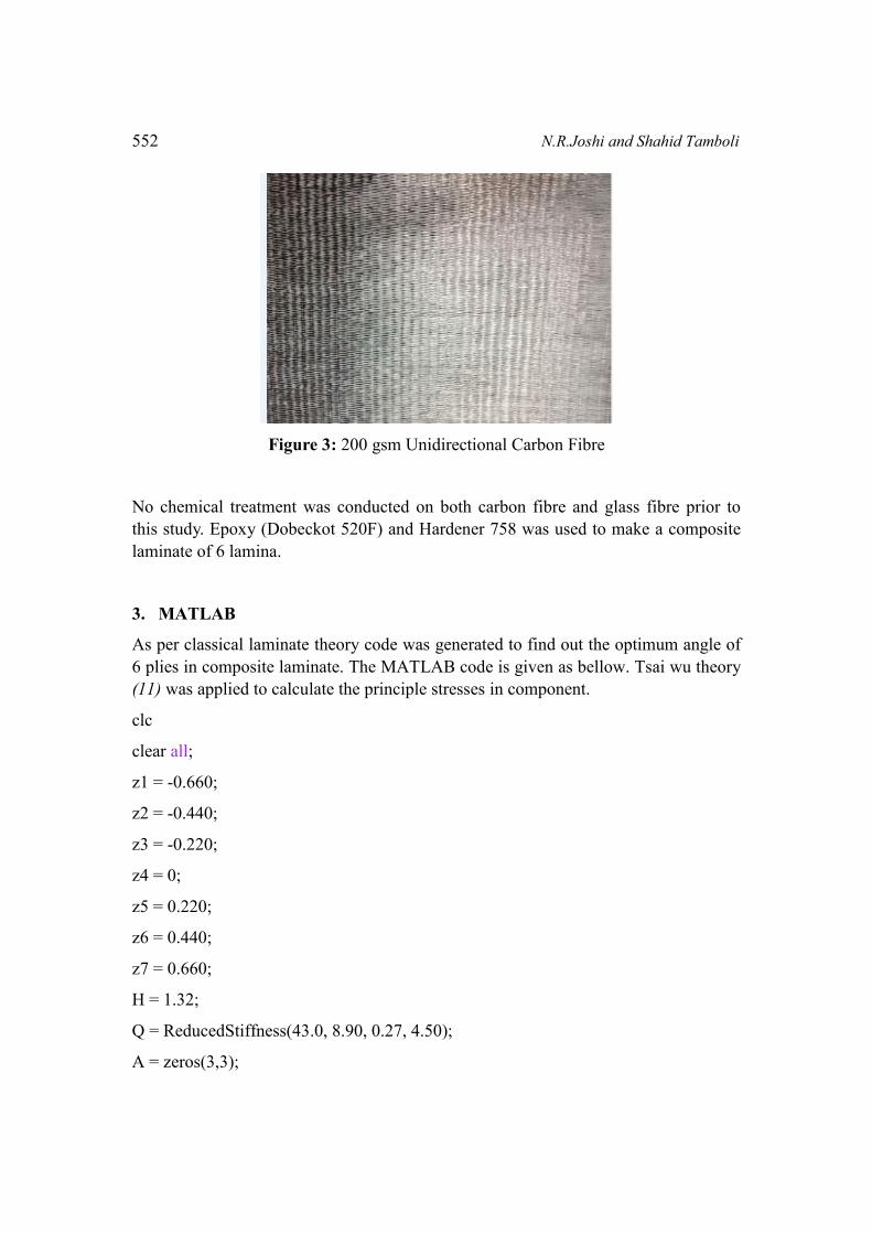
Figure 3: 200 gsm Unidirectional Carbon Fibre
No chemical treatment was conducted on both carbon fibre and glass fibre prior to
this study. Epoxy (Dobeckot 520F) and Hardener 758 was used to make a composite
laminate of 6 lamina.
3. MATLAB
As per classical laminate theory code was generated to find out the optimum angle of
6 plies in composite laminate. The MATLAB code is given as bellow. Tsai wu theory
(11) was applied to calculate the principle stresses in component.
clc
clear all;
z1 = -0.660;
z2 = -0.440;
z3 = -0.220;
z4 = 0;
z5 = 0.220;
z6 = 0.440;
z7 = 0.660;
H = 1.32;
Q = ReducedStiffness(43.0, 8.90, 0.27, 4.50);
A = zeros(3,3);

Optimum Orientation of Fibre Direction in Composite Lamina 553
for a=10:10:80
A=zeros(3,3);
c=0;
b=10;
d=10+a;
e=d;
f=b;
g=c;
Qbar1 = Qbar(Q, c);
Qbar2 = Qbar(Q, b);
Qbar3 = Qbar(Q, d);
Qbar4 = Qbar(Q, e);
Qbar5 = Qbar(Q, f);
Qbar6 = Qbar(Q, g) ;
A = Amatrix(A,Qbar1,z1,z2);
A = Amatrix(A,Qbar2,z2,z3);
A = Amatrix(A,Qbar3,z3,z4);
A = Amatrix(A,Qbar4,z4,z5);
A = Amatrix(A,Qbar5,z5,z6);
A = Amatrix(A,Qbar6,z6,z7);
fprintf('%8.3f %8.3f %8.3f %8.3f %8.3f %8.3f\n',c,b,d,e,f,g);
fprintf('%8.3f\n',Ebarx(A,H))
fprintf('%8.3f\n',Ebary(A,H))
end

554 N.R.Joshi and Shahid Tamboli
750 cases of different ply angles were generated by permutation and combination.
The angles of plies were varied by 10 degree. As the angle of fibre were varied in
each lamina, the final value of modulus E in x and y direction changed for the entire
laminate. Simulation in MATLAB was run using above code and the Ex and Ey
values for different cases were obtained for carbon and glass fibre. For individual
lamina properties mentioned in Table no. 1 were considered.
Figure 4 to 7 shows the values of Ex and Ey (on y axis) for various laminates (on x
axis).The laminates have fibres at different angles and different combinations. From
figure 4 to 7 it can be concluded that a higher value of modulus Ex in x directions is
associated with lower value of Ey in y direction. This is particularly suitable if the
loading is in one direction only. Table no. 2 shows the values for such cases.
Table no. 2: High value of Modulus in single direction.
Sr.
No
Cases Carbon Fibre
Ex(GPa)
Carbon Fibre
Ey(GPa)
Glass Fibre
Ex(GPa)
Glass Fibre
Ey(GPa)
1 0/0/0/0/0/0 132.0 8.830 43.0 8.90
2 90/90/90/90/90/90 8.830 132.0 8.90 43.0
In unidirectional loading case the particular combination which gives higher value of
Ex can be used. Since the objective chosen for this study is Bi axial tensile loading,
different combinations were picked up where trade off is obtained between Ex and Ey
values. Few of such combinations are mentioned in Table no. 3.
Table no. 3: Few selected combinations for trade off values of modulus in both
directions.
Sr
no
Ply combination Carbon Fibre
Ex(GPa)
Carbon Fibre
Ey(GPa)
Glass Fibre
Ex(GPa)
Glass Fibre
Ey(GPa)
1 0/10/20/20/10/0 74.632 8.778 31.030 8.551
2 0/10/30/30/10/0 74.273 9.344 28.928 8.723
3 0/10/40/40/10/0 76.658 10.425 28.410 9.274
4 0/10/50/50/10/0 79.073 12.313 28.679 10.304
5 0/10/60/60/10/0 80.465 15.801 29.252 12.034
6 0/10/70/70/10/0 80.235 22.878 29.762 14.794
7 0/10/80/80/10/0 78.324 37.218 29.871 18.405
9 0/10/90/90/10/0 75.658 50.111 29.431 20.272
10 0/20/20/20/20/0 60.789 8.637 26.501 8.338

Optimum Orientation of Fibre Direction in Composite Lamina 555
It can be seen from the above table and the Figures 4 to 7 that 0/10/90/90/10/0 give
high values of Ex and Ey respectively.
Figure 4. Graph of Ex vs. Cases for carbon fibre Figure 5. Graph of Ey vs Cases
for carbon fibre
Figure 6. Graph of Ex vs Cases for Glass fibre Figure 7. Graph of Ey vs Cases for
Glass fibre
4. SIMULATION
The simulation for composite laminate for (0/10/90/90/10/0) and (0/90/90/90/90/0)
was done with LS Dyna software whereas meshing was done with Hypermesh 12
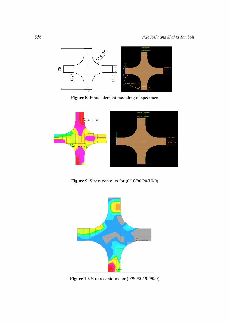
software. For meshing shell elements were used. As shown in Figure 8 top and right
end of the sample and their respective opposite ends were fixed. Time step of 1
microsec. was taken to apply a load of 2.5 kN on both the sides. Material properties
were defined in MAT 54 material card. Figure 9 shows the stress contours for the case
(0/10/90/90/10/0) whereas Figure 10 shows the contours for (0/90/90/90/90/0).
556 N.R.Joshi and Shahid Tamboli
Figure 8. Finite element modeling of specimen
Figure 9. Stress contours for (0/10/90/90/10/0)
Figure 10. Stress contours for (0/90/90/90/90/0)
Optimum Orientation of Fibre Direction in Composite Lamina 557
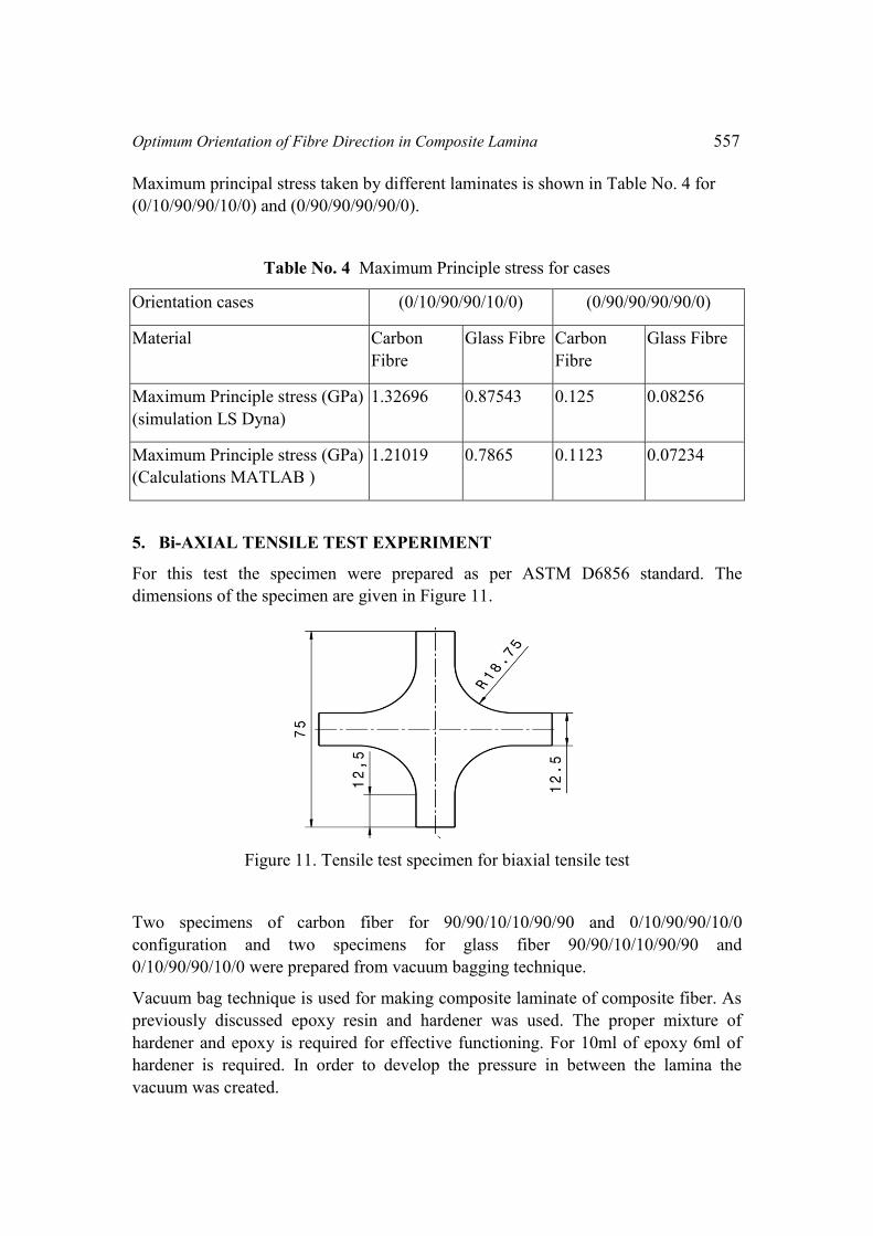
Maximum principal stress taken by different laminates is shown in Table No. 4 for
(0/10/90/90/10/0) and (0/90/90/90/90/0).
Table No. 4 Maximum Principle stress for cases
Orientation cases (0/10/90/90/10/0) (0/90/90/90/90/0)
Material Carbon
Fibre
Glass Fibre Carbon
Fibre
Glass Fibre
Maximum Principle stress (GPa)
(simulation LS Dyna)
1.32696 0.87543 0.125 0.08256
Maximum Principle stress (GPa)
(Calculations MATLAB )
1.21019 0.7865 0.1123 0.07234
5. Bi-AXIAL TENSILE TEST EXPERIMENT
For this test the specimen were prepared as per ASTM D6856 standard. The
dimensions of the specimen are given in Figure 11.
Figure 11. Tensile test specimen for biaxial tensile test
Two specimens of carbon fiber for 90/90/10/10/90/90 and 0/10/90/90/10/0
configuration and two specimens for glass fiber 90/90/10/10/90/90 and
0/10/90/90/10/0 were prepared from vacuum bagging technique.
Vacuum bag technique is used for making composite laminate of composite fiber. As
previously discussed epoxy resin and hardener was used. The proper mixture of
hardener and epoxy is required for effective functioning. For 10ml of epoxy 6ml of
hardener is required. In order to develop the pressure in between the lamina the
vacuum was created.

558 N.R.Joshi and Shahid Tamboli
Figure 12. Vacuum Bag technique
From the bi-axial testing of above four specimens first ply failure was observed as
given in the following Table No. 5
Table No. 5 First ply failure stresses
Configuration Carbon fiber(stresses
GPa)
Glass Fiber(stresses GPa)
0/0/10/10/0/0 0.822122 0.541212
0/10/10/10/10/0 0.72143 0.433312
90/90/10/10/90/90 0.891321 0.311154
From the above values it can be concluded that the optimum configuration given by
MATLAB code is validated in LS Dyna where more stresses were observed in
another configuration. The same thing was observed in actual mechanical testing also.
Wherein optimum configuration took more load than the other configurations. The
code gave similar results for glass fiber also. From the observations it had been
concluded that for bi axial tensile test best orientation is 0/10/90/90/10/0.
6. CONCLUSION
The outcome of the present work is the effect of orientation of angles on mechanical
properties of composite lamina. The effect of bi axial tensile force was investigated on
carbon fibre and Glass fibre. The optimum angles configuration was 0/10/90/90/10/0
for both the materials for a good bi axial strength. Experimental study confirmed the
outcome of MATLAB code.
Optimum Orientation of Fibre Direction in Composite Lamina 559
As a future scope of study optimum fiber orientation can be found out for a bi-axial
loading wherein the loading directions are not perpendicular to each other.
REFERENCES
1. Improving the strength and service life of jute/epoxy laminar composites. M.
Pinto, V.B. Chalivendra , Y.K. Kim, A.F. Lewis. 2015, composite structure .
2. An analytical approach for bending and stress analysis of cross/angle-ply
laminated compositeplates under arbitrary non-uniform loads and elastic
foundations. Alipour, M.M. s.l. : archieve of civil and mechanical engineering ,
2016, Vols. 193-210.
3. Optimum design of composite laminates for minimum thickness. Mustafa
Akbulut, Fazil O. Sonmez. s.l. : Computers and Structures, 2008, Vol. 86.
4. A global numerical approach for lightweight design optimization of laminated.
T. Vo-Duy, V. Ho-Huu, T.D. Do-Thi, H. Dang-Trung, T. Nguyen-Thoi. s.l. :
Composite Structures, 2016.
5. An experimental/numerical investigation into the main driving force for crack
propagation in uni-directional fibre-reinforced composite laminae. L.M.A.
Cahill, S. Natarajan , S.P.A. Bordas , R.M. O’Higgins , C.T. McCarthy. 2014,
Vol. 107.
6. Optimum in situ strength design of laminates under combined mechanical and
thermal loads. J. Wang, B.L. Karihaloo. s.l. : Composite Structures, 1999, Vols.
635-641.
7. Experimental Investigations on Mechanical Properties Of Jute Fiber Reinforced
Composites with Polyester and Epoxy Resin Matrices. Ajith Gopinatha, Senthil
Kumar.M, Elayaperumal A. s.l. : Procedia Engineering, 2014, Vols. 2052 –
2063.
8. Predicting the Tensile Modulus of Randomly Oriented Nonwoven Kenaf/Epoxy
Composites. N. G. Andre, Z. A. Mohd. Ishak. s.l. : Procedia Chemistry, 2016,
Vols. 419-425.
9. Optimum in situ strength design of laminates under combined mechanical and
thermal loads. J. Wang, B.L. Karihaloo. 635-641, s.l. : Composite Structures,
1999, Vol. 47.
10. Jones, Robert M. Mechanics of composite material .
11. LS Dyna Keywords user manual . May 2007.

560 N.R.Joshi and Shahid Tamboli