optimumantennadowntiltanglesfor macrocellularwcdmanetwork · optimumantennadowntiltanglesfor...
TRANSCRIPT
EURASIP Journal on Wireless Communications and Networking 2005:5, 816–827c© 2005 Jarno Niemela et al.
OptimumAntenna Downtilt Angles forMacrocellular WCDMANetwork
Jarno NiemelaInstitute of Communications Engineering, Tampere University of Technology, P.O. BOX 553,33101 Tampere, FinlandEmail: [email protected]
Tero IsotaloInstitute of Communications Engineering, Tampere University of Technology, P.O. BOX 553,33101 Tampere, FinlandEmail: [email protected]
Jukka LempiainenInstitute of Communications Engineering, Tampere University of Technology, P.O. BOX 553,33101 Tampere, FinlandEmail: [email protected]
Received 3 January 2005; Revised 12 May 2005; Recommended for Publication by Pascal Chevalier
The impact of antenna downtilt on the performance of cellular WCDMA network has been studied by using a radio network plan-ning tool. An optimum downtilt angle has been evaluated for numerous practical macrocellular site and antenna configurationsfor electrical and mechanical antenna downtilt concepts. The aim of this massive simulation campaign was expected to providean answer to two questions: firstly, how to select the downtilt angle of a macrocellular base station antenna? Secondly, what isthe impact of antenna downtilt on system capacity and network coverage? Optimum downtilt angles were observed to vary be-tween 3.5◦–10.5◦ depending on the network configuration. Moreover, the corresponding downlink capacity gains varied between0–58%. Antenna vertical beamwidth affects clearly the required optimum downtilt angle the most. On the other hand, with widerantenna vertical beamwidth, the impact of downtilt on system performance is not such imposing. In addition, antenna heighttogether with the size of the dominance area affect the required downtilt angle. Finally, the simulation results revealed how theimportance of the antenna downtilt becomes more significant in dense networks, where the capacity requirements are typicallyalso higher.
Keywords and phrases: electrical downtilt, other-cell interference, mechanical downtilt, network coverage, system capacity,WCDMA.
1. INTRODUCTION
The majority of the current third-generation mobile com-munication systems use CDMA (code-division multiple ac-cess) technique as a multiple-access method. Due to itsinterference-limited nature, the system capacity of any cellu-lar CDMA network is vulnerable to any additional other-cellinterference. Therefore, in a CDMA radio network planningprocess, the main target is to plan the network in such aman-ner that other-cell interference is minimized in order to beable to maximize the system capacity. This can be achieved,among all other techniques, by optimizing the network
This is an open access article distributed under the Creative CommonsAttribution License, which permits unrestricted use, distribution, andreproduction in any medium, provided the original work is properly cited.
topology. One important phase of the topology planning1 isthe definition of antenna configuration, and especially, an-tenna downtilt angle. By utilizing antenna downtilt, signallevel within a cell can be improved and interference radi-ation towards other cells effectively reduced due to moreprecise aiming of the antenna radiation pattern. However,an excessive downtilt angle might lead to coverage problemsat cell border areas. Therefore, it is vital to define an op-timum downtilt angle separately for each site and antennaconfiguration.
Antenna downtilt includes two different concepts—mechanical downtilt (MDT) and electrical downtilt (EDT).
1The target of topology planning is to optimize site and antenna config-uration in such a manner that cells become as isolated as possible.
Antenna Downtilt for WCDMA 817
Utilization of antenna mechanical downtilt has been a toolfor radio network planners to optimize networks. It hasbeen observed to be an efficient method to reduce other-cell interference in the main-lobe direction [1]. Hence, MDTis widely used in TDMA/FDMA (time-division multipleaccess/frequency-division multiple access) networks as inGSM (Global System for Mobile Communications) to de-crease co-channel interference. However, in GSM, utilizationof downtilt targets in achieving a smaller frequency reuse fac-tor. Therefore, any improvements in the radio network qual-ity due to antenna downtilt have not been directly taken intoaccount in capacity or frequency planning phases in prac-tice, but have been used as an extra margin to avoid seri-ous interference areas [2]. Nevertheless, capacity gains up to20% have been reported from utilization of MDT in GSMnetworks [3]. This reduction of other-cell interference af-fects especially macrocellular WCDMA (wideband CDMA)networks [4], where the achievable capacity gain from MDThas been observed to vary between 15% and 20% [5, 6, 7].Moreover, MDT is able to enhance system capacity in mi-crocellular environment [8, 9], even though the contributionof other-cell interference is typically smaller in microcellularenvironment.
In an interference-limited WCDMA system, suppressionof side and back lobes of an antenna would be advantageousdue to further reduction of other-cell interference. Therefore,electrically downtilted antennas might become an attractivechoice for antenna selection. In EDT, the vertical radiationpattern is uniformly downtilted in all horizontal directions—contrary to mechanical downtilt. Prior work [10] have re-ported capacity gains up to 50% and 20% for 3-sectored and6-sectored sites, respectively, with corresponding optimumdowntilt angles of 7◦–10◦. On the contrary, in [11], optimumEDT angles have been defined on site-by-site basis using aniterative algorithm.Moreover, optimumdowntilt angles werefound to vary between 6◦–8◦, and to provide capacity gainup to 15% with practical macrocellular network configura-tions. Naturally, an increasing impact of EDT on the systemcapacity has been observed in microcellular environment aswell [12]. Recently, one direction of research concerning an-tenna downtilt has been concentrated on adaptively and re-motely controlled EDT according to changes in the load oruser distribution within a cell [13]. Compared to utilizationof a static network-wide downtilt angle, dynamically chang-ing downtilt angle can further boost the system capacity by20–30% under certain circumstances [14].
The aim of this paper is to extend the prior work ofthe authors in [7, 15], to present a simultaneous analysisof mechanical and electrical antenna downtilt concepts inWCDMA macrocellular network, and to evaluate optimumdowntilt angles for different practical base station site andantenna configurations for suburban environment by utiliz-ing a static radio network planning tool. Furthermore, thetarget is to identify and analyze the most important phe-nomena resulting from utilization of antenna downtilt andto clarify the sensitivity of the selection of downtilt angle. Fi-nally, capacity gains of network-wide static antenna downtiltare provided for all simulated network configurations.
2. CAPACITY OFWCDMANETWORK
In cellular WCDMA system, the same carrier frequency isused in all cells, and users are separated by unique code se-quences. The capacity of WCDMA system is thus typicallyinterference-limited rather than blocking-limited, since allmobiles and base stations interfere with each others in up-link and downlink directions. Furthermore, the network (orcell) capacity is defined by the load equations that, on theother hand, set limits for the maximum number of users ina cell or for the maximum cell throughput. The system ca-pacity is defined in this context as the maximum number ofusers that can be supported simultaneously with a predefinedservice probability target.
2.1. Uplink capacity
Energy-per-bit-to-noise spectral density ratio, Eb/N0, is usedto measure the quality of a connection. In the uplink (UL)direction, the signal quality received at the base station forthe jth user must satisfy the following condition:
(EbN0
)j= (W/Rj)pTX, j
PBSRXLj − pTX, j
, (1)
where W is the system chip rate, Rj is the bit rate of the jthmobile, pTX, j is the transmit (TX) power of the jth mobile,PBSRX is the total received wideband power2 at the base station,
and Lj is the uplink path loss from the jth mobile to the basestation. The maximum uplink capacity is defined by the up-link load factor, ηUL, which is given as interference rise abovethe thermal noise power:
ηUL = PBSRX − pnPBSRX
, (2)
where pn is the thermal noise power at the base station.The load factor is used to define a radio network plan-
ning parameter called interference margin3 (IM) that takesinto account the changes in the network coverage due to cellbreathing:
IM = −10 log10(1− ηUL
). (3)
2.2. Downlink capacity
The capacity of the downlink (DL) in WCDMA system be-haves differently compared to the uplink. This is caused bythe fact that all mobiles share the same transmit power ofa base station sector. Furthermore, simultaneous transmis-sion allows the usage of orthogonal codes. However, the codeorthogonality α is partly destroyed by multipath propaga-tion, which depends on the propagation environment, mo-bile speed, and mobile location. In order to satisfy the Eb/N0
2The total wideband power includes thermal noise, and received powersfrom mobiles in own cell as well as from other cells.
3Interference margin is also called noise rise.
818 EURASIP Journal on Wireless Communications and Networking
30
60
90
120
150
180
210
240
270
300
330
0
0◦2◦4◦6◦8◦
0 dB
−10 dB−20 dB
−30 dB−40 dB
(a)
30
60
90
120
150
180
210
240
270
300
330
0
0◦2◦4◦6◦8◦
0 dB
−10 dB−20 dB
−30 dB−40 dB
(b)
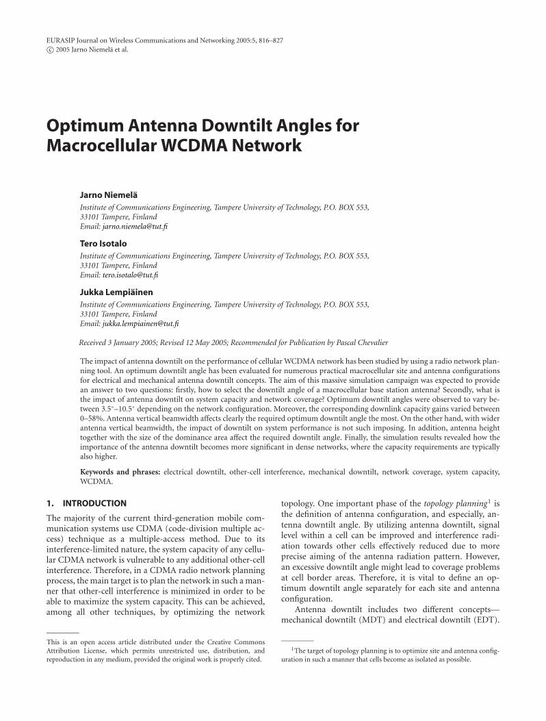
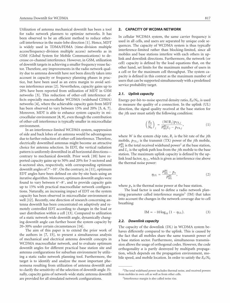
Figure 1: The impact of antenna (a) mechanical and (b) electrical downtilts on the horizontal (azimuthal) radiation pattern in the boresight.Antenna gain is normalized to zero and the scale is in decibels. “Uptilt” of back-lobe direction for mechanical downtilt is not illustrated.
requirement of the kth mobile in the DL, the following crite-rion has to be fulfilled:
(EbN0
)k= (W/Rk)pTCH,k
PMSRX Lk − αPTOT
TX − (1− α)pTCH,k. (4)
In (4), pTCH,k is the downlink traffic channel (TCH) TXpower for the kth connection, PMS
RX is the total received wide-band power at the mobile station, Lk is the downlink pathloss, and PTOT
TX is the total TX power of a base station the sec-tor mobile is connected to. The parameter PTOT
TX includes theTX power of common pilot channel (CPICH), other com-mon channels (CCCH), and traffic channels as well. The totaltransmit power PTOT
TCH,m for the TCH of the mth base stationsector is thus the sum of all K connections (including softand softer handover connections):
PTOTTCH,m =
K∑k=1
pTCH,k. (5)
The downlink load factor, ηDL, is defined with the aid ofthe average transmit power of TCHs of base stations for acluster of cells:
ηDL =∑M
m=1 PTOTTCH,m
MPmaxTCH,m
, (6)
where M is the number of sectors in the cluster. Thedownlink capacity is maximized when the minimum ηDL isachieved with the same number of served users K .
3. ANTENNADOWNTILT
3.1. Downtilt concepts
In mechanical downtilt (MDT), the antenna element is phys-ically directed towards the ground. Naturally, the areas nearthe base station experience better signal level due to the factthat the antennamain lobe is more precisely directed towardsthe intended dominance (serving) area. However, the effec-tive downtilt angle corresponds to the physical one only ex-actly in the main-lobe direction, and decreases as a functionof horizontal direction in such a way that the antenna radia-tion pattern is not downtilted at all in the side-lobe direction[1]. Nevertheless, interference radiation towards other cellsis reduced in the main-lobe direction. The relative wideningof the horizontal radiation pattern is illustrated in Figure 1afor a horizontally 65◦ and vertically 6◦ wide antenna beamas a function of increasing downtilt angle. The reduction ofthe antenna gain towards the boresight, for example, with 8◦
downtilt angle, is as large as 25 dB, whereas towards 60◦ anglethe reduction is less than 10 dB.
As the downtilt angle increases, the soft handover (SHO)probability in the cell border areas decreases [16]. On theother hand, the relative widening of the horizontal radiationpattern increases the overlapping between adjacent sectors,which makes softer handovers (SfHO) more attractive. Thisincrease of softer handovers as a function of downtilt angledepends on sector overlapping (i.e., sectoring and antennahorizontal beamwidth) [7, 17].
Antenna electrical downtilt (EDT) is carried out by ad-justing the relative phases of antenna elements of an an-tenna array in such a way that the radiation pattern canbe downtilted uniformly in all horizontal directions [18].This technique changes slightly the vertical radiation pattern
Antenna Downtilt for WCDMA 819
depending on the chosen EDT angle. Figure 1b illustrates thebehavior of the horizontal radiation pattern for 65◦ and ver-tically 6◦ wide antenna beam. EDT reduces efficiently radi-ation also towards the adjacent sectors, since all directionsare downtilted uniformly. However, the coverage in the side-lobe direction reduces rapidly as well, which deteriorates thenetwork performance if antennas are downtilted excessively.Naturally, SHO probability decreases as the downtilt angleincreases, whereas SfHO probability should not change re-markably [15, 17].
3.2. Downtilt schemes
Fundamentally, there are two concepts for downtilt—mechanical and electrical. However, there exist many differ-ent tilting schemes including purely mechanical tilt, fixedelectrical tilt, variable electrical tilt (VET), remote electri-cal tilt (RET), and continuously adjustable electrical down-tilt (CAEDT). Adjusting antenna mechanical downtilt anglerequires a site visit, which makes the adjustment process oftilt angles more expensive and time consuming. Hence, ifMDT is utilized, the importance of the selection of an opti-mummechanical tilt angle in the network deployment phaseshould be of great importance. Fixed electrical tilt antennasrequire also a site visit in order to change the tilt angle. How-ever, if the fixed electrical tilt angle is wanted to change elec-trically, it requires a totally new antenna, or tilt angle is fur-ther increased/decreased purely mechanically (combined tiltscheme). In VET antennas, an electrical downtilt angle is ad-justable in the dynamic range of downtilt angle. A typicalrange for tilt angles for macrocellular antennas vary from 0◦
to 12◦ depending on the vertical beamwidth [19, 20]. Utiliza-tion of RET scheme removes the need for a site visit, since tiltangles can be changed from network management system.Hence, it saves the costs and time in optimization during net-work evolution. An improvement of RET scheme is CAEDTscheme, in which downtilt angle can be changed continu-ously and remotely according to changes, for example, inpropagation environment or in load distribution of a cell.Nevertheless, no matter what the utilized downtilt schemeis, knowledge about the initial optimum downtilt angle isneeded in order to maximize the capacity and quality.
3.3. Selection of downtilt angle
The selection of antenna downtilt angle depends on the siteand antenna configuration, and hence it has to be set on site-by-site basis in practice. In WCDMA, an optimum downtiltangle is obviously a tradeoff between other-cell interferencemitigation and coverage thresholds. The optimum down-tilt angle is achieved if other-cell interference is reduced tothe minimum achievable level while still providing the targetcoverage.
An optimum downtilt angle—either for MDT or EDT—depends partly on the same factors. Perhaps two most obvi-ous ones are the geometrical factor (θgeo) and antenna ver-tical beamwidth factor (θBWver ). The geometrical factor takesinto account the average height difference between the basestation (hBS) and mobile station antenna (hMS) as well as the
size of the sector dominance area (d):
θgeo = arctan(hBS − hMS
d
). (7)
Intuitively, an increase of the antenna height should alsoincrease the required downtilt angle and vice versa. Corre-spondingly, a cell with a small dominance area should requirea larger downtilt angle. However, the geometrical factor assuch is not enough to define the required downtilt angle, asit does not take into account any information about antennavertical beamwidth. One possibility is to select the antennabeamwidth factor as half of the antenna half-power (−3dB)vertical beamwidth (θ−3dB). Thus, the selection of geomet-rical downtilt angle (νgeo) could be performed as in [21]:
νgeo = θgeo +θ−3dB
2. (8)
4. SIMULATIONS
4.1. Network configuration
The impact of different network configurations on the opti-mum downtilt angles is simulated by using a static WCDMAradio network simulator that utilizes Monte Carlo techniquefor capacity and performance analysis. For the system-levelanalysis, a macrocellular network is configured in a shapeof a regular hexagonal grid of 19 base stations. The selectedantenna heights—25m, 35m, and 45m—exceed the aver-age roof-top level that dominates in the simulation area.The site spacings in the simulations are 1.5 km, 2.0 km, and2.5 km. The sectoring schemes adopted in the simulation are3-sectored and 6-sectored sites. Moreover, the base stationantennas are oriented to have equal directions (see Figure 2).For the 3-sectored sites, the horizontal beamwidth (BW) ofthe antennas is 65◦ and vertical one either 6◦ or 12◦ withcorresponding antenna gains of 18 dBi and 15.2dBi. On thecontrary, for the 6-sectored sites, horizontally 33◦ beamwidthand vertically 6◦ beamwidth antennas are utilized with cor-responding antenna gain of 21 dBi. All radiation patterns ofthe base station antennas are adopted from [19]. Finally, theselected site and antenna configurations are the following:4
(i) EDT 3-sectored sites with 65◦/6◦,(ii) EDT 3-sectored sites with 65◦/12◦,(iii) EDT 6-sectored sites with 33◦/6◦,(iv) MDT 3-sectored sites with 65◦/6◦,(v) MDT 3-sectored sites with 65◦/12◦,(vi) MDT 6-sectored sites with 33◦/6◦.
Morphological and topographic information of the sim-ulation area is defined by a high resolution (5m×5m) digitalmap. The digital map includes the basic terrain types (wa-ter, open, and forest) and buildings of different heights in a
465◦/6◦ denotes horizontal/vertical half-power beamwidth.
820 EURASIP Journal on Wireless Communications and Networking
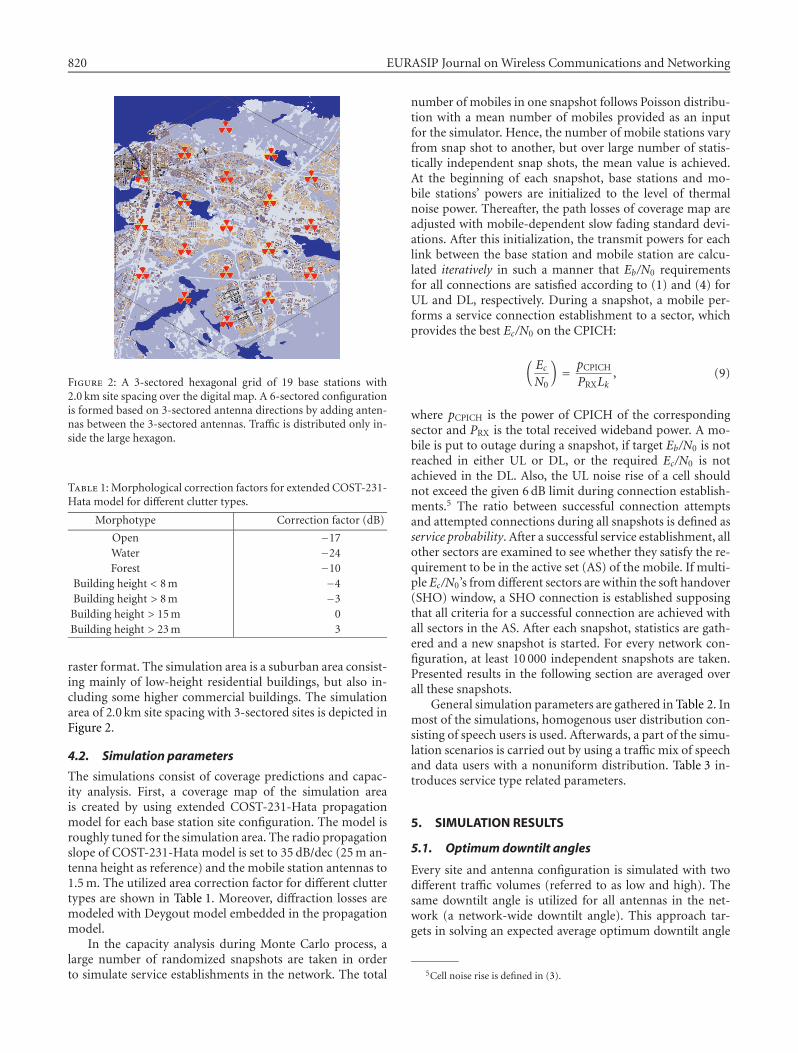
Figure 2: A 3-sectored hexagonal grid of 19 base stations with2.0 km site spacing over the digital map. A 6-sectored configurationis formed based on 3-sectored antenna directions by adding anten-nas between the 3-sectored antennas. Traffic is distributed only in-side the large hexagon.
Table 1: Morphological correction factors for extended COST-231-Hata model for different clutter types.
Morphotype Correction factor (dB)
Open −17Water −24Forest −10
Building height < 8m −4Building height > 8m −3Building height > 15m 0Building height > 23m 3
raster format. The simulation area is a suburban area consist-ing mainly of low-height residential buildings, but also in-cluding some higher commercial buildings. The simulationarea of 2.0 km site spacing with 3-sectored sites is depicted inFigure 2.
4.2. Simulation parameters
The simulations consist of coverage predictions and capac-ity analysis. First, a coverage map of the simulation areais created by using extended COST-231-Hata propagationmodel for each base station site configuration. The model isroughly tuned for the simulation area. The radio propagationslope of COST-231-Hata model is set to 35 dB/dec (25m an-tenna height as reference) and the mobile station antennas to1.5m. The utilized area correction factor for different cluttertypes are shown in Table 1. Moreover, diffraction losses aremodeled with Deygout model embedded in the propagationmodel.
In the capacity analysis during Monte Carlo process, alarge number of randomized snapshots are taken in orderto simulate service establishments in the network. The total
number of mobiles in one snapshot follows Poisson distribu-tion with a mean number of mobiles provided as an inputfor the simulator. Hence, the number of mobile stations varyfrom snap shot to another, but over large number of statis-tically independent snap shots, the mean value is achieved.At the beginning of each snapshot, base stations and mo-bile stations’ powers are initialized to the level of thermalnoise power. Thereafter, the path losses of coverage map areadjusted with mobile-dependent slow fading standard devi-ations. After this initialization, the transmit powers for eachlink between the base station and mobile station are calcu-lated iteratively in such a manner that Eb/N0 requirementsfor all connections are satisfied according to (1) and (4) forUL and DL, respectively. During a snapshot, a mobile per-forms a service connection establishment to a sector, whichprovides the best Ec/N0 on the CPICH:
(EcN0
)= pCPICH
PRXLk, (9)
where pCPICH is the power of CPICH of the correspondingsector and PRX is the total received wideband power. A mo-bile is put to outage during a snapshot, if target Eb/N0 is notreached in either UL or DL, or the required Ec/N0 is notachieved in the DL. Also, the UL noise rise of a cell shouldnot exceed the given 6dB limit during connection establish-ments.5 The ratio between successful connection attemptsand attempted connections during all snapshots is defined asservice probability. After a successful service establishment, allother sectors are examined to see whether they satisfy the re-quirement to be in the active set (AS) of the mobile. If multi-ple Ec/N0’s from different sectors are within the soft handover(SHO) window, a SHO connection is established supposingthat all criteria for a successful connection are achieved withall sectors in the AS. After each snapshot, statistics are gath-ered and a new snapshot is started. For every network con-figuration, at least 10 000 independent snapshots are taken.Presented results in the following section are averaged overall these snapshots.
General simulation parameters are gathered in Table 2. Inmost of the simulations, homogenous user distribution con-sisting of speech users is used. Afterwards, a part of the simu-lation scenarios is carried out by using a traffic mix of speechand data users with a nonuniform distribution. Table 3 in-troduces service type related parameters.
5. SIMULATION RESULTS
5.1. Optimumdowntilt angles
Every site and antenna configuration is simulated with twodifferent traffic volumes (referred to as low and high). Thesame downtilt angle is utilized for all antennas in the net-work (a network-wide downtilt angle). This approach tar-gets in solving an expected average optimum downtilt angle
5Cell noise rise is defined in (3).
Antenna Downtilt for WCDMA 821
Table 2: General simulation parameters.
Parameter Value
BS TX Pmax (dBm) 43Max. BS TX per connection (dBm) 38BS noise figure (dB) 5CPICH TX power (dBm) 33CCCH TX power (dBm) 33SHO window (dB) 4Outdoor/indoor STD for shadow fading (dB) 8/12Building penetration loss (dB) 15UL target noise rise limit (dB) 6DL code orthogonality 0.6Maximum active set size 3
for a certain site and antenna configuration. Note that thetarget is not to seek the same downtilt angle for a part ofa network, but to find an optimum downtilt angle depend-ing on the site and antenna configuration. The definition ofan optimum downtilt angle (ODA) is based on maximumservice probability of low and high traffic volume scenarios.Hence, with an optimum downtilt angle, network coverageis guaranteed, and simultaneously, other-cell interference ismitigated as efficiently as possible. More detailed descriptionof the definition method of ODA can be found from [15]. Inthe simulations, all downtilt angles are gradually increased insteps of 2◦.
Table 4 gathers all optimum downtilt angles for all simu-lated network configurations. For all network configurations,ODAs increase as a function of antenna height and decreaseas a function of site spacing. Generally, it can be observedthat a change of ODA from 1.5 km to 2.0 km site spacing ishigher than from 2.0 km to 2.5 km, hence indicating that asmall downtilt angle should be always used. Moreover, with12◦ antennas, the required downtilt angles are expectedlyhigher than for 6◦ antennas.
For the 3-sectored configurations with 6◦ verticalbeamwidth, the optimum downtilt angle varies between4.3◦–8.1◦ depending on the network configuration anddowntilt scheme. According to (7) and (8), the correspond-ing downtilt angles would have been 0.8◦–2.5◦ and 3.8◦–5.5◦.The simulation results indicate that an increase of the an-tenna height changes expectedly the optimum downtilt an-gle; 10m increase in the antenna height corresponds roughlyto 1◦ increase of the ODA. On the other hand, site spac-ing has comparatively smaller impact on ODAs, especiallywith larger site spacings. In the 3-sectored configurationswith 12◦ vertical beamwidth, the evaluated optimum down-tilt angles range between 3.5◦–10◦ (Table 4). With definitionsof (7) and (8), the downtilt angles would have been 0.8◦–2.5◦ and 6.8◦–8.5◦, respectively. On average, the ODAs areintuitively higher for the 12◦ than for 6◦ beamwidth. How-ever, the increase of ODAs is not as huge as one could ex-pect. One reason for even lower ODAs for 12◦ beamwidth arethe interference conditions that differ due to lower antennagain and wider vertical spread of antenna pattern. Withoutany downtilt with 6◦ beamwidth, the signal power is more
precisely directed towards the boresight, whereas antennasof 12◦ beamwidth provide better coverage also in the areascloser to the base station in nontilted scenarios. This resultsin lower other-cell interference levels, but on the contrary,prevents high capacity gains.
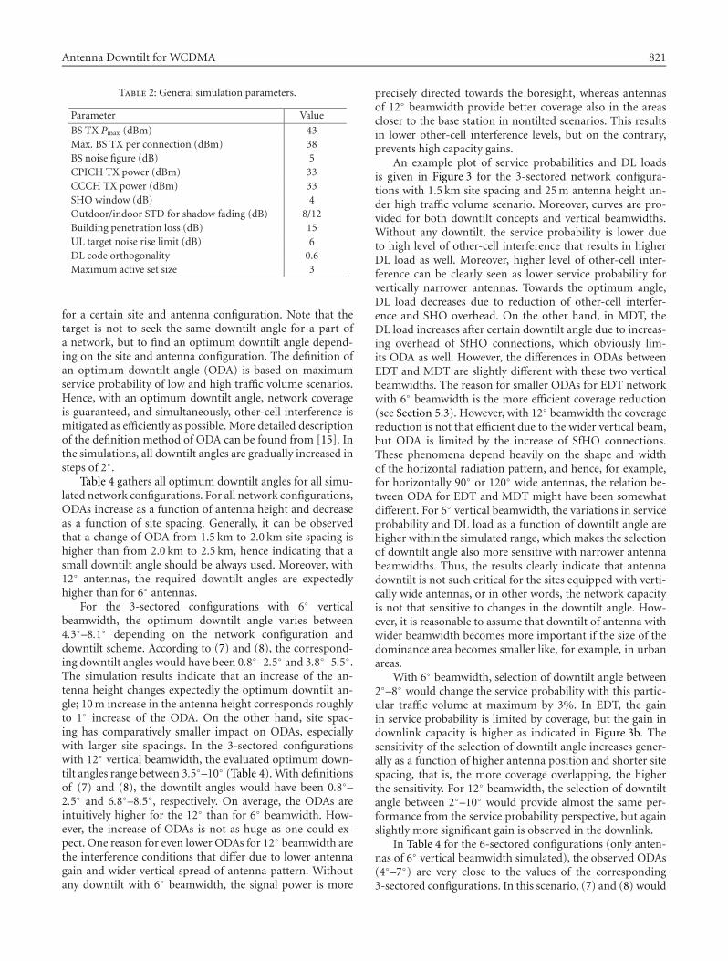
An example plot of service probabilities and DL loadsis given in Figure 3 for the 3-sectored network configura-tions with 1.5 km site spacing and 25m antenna height un-der high traffic volume scenario. Moreover, curves are pro-vided for both downtilt concepts and vertical beamwidths.Without any downtilt, the service probability is lower dueto high level of other-cell interference that results in higherDL load as well. Moreover, higher level of other-cell inter-ference can be clearly seen as lower service probability forvertically narrower antennas. Towards the optimum angle,DL load decreases due to reduction of other-cell interfer-ence and SHO overhead. On the other hand, in MDT, theDL load increases after certain downtilt angle due to increas-ing overhead of SfHO connections, which obviously lim-its ODA as well. However, the differences in ODAs betweenEDT and MDT are slightly different with these two verticalbeamwidths. The reason for smaller ODAs for EDT networkwith 6◦ beamwidth is the more efficient coverage reduction(see Section 5.3). However, with 12◦ beamwidth the coveragereduction is not that efficient due to the wider vertical beam,but ODA is limited by the increase of SfHO connections.These phenomena depend heavily on the shape and widthof the horizontal radiation pattern, and hence, for example,for horizontally 90◦ or 120◦ wide antennas, the relation be-tween ODA for EDT and MDT might have been somewhatdifferent. For 6◦ vertical beamwidth, the variations in serviceprobability and DL load as a function of downtilt angle arehigher within the simulated range, whichmakes the selectionof downtilt angle also more sensitive with narrower antennabeamwidths. Thus, the results clearly indicate that antennadowntilt is not such critical for the sites equipped with verti-cally wide antennas, or in other words, the network capacityis not that sensitive to changes in the downtilt angle. How-ever, it is reasonable to assume that downtilt of antenna withwider beamwidth becomes more important if the size of thedominance area becomes smaller like, for example, in urbanareas.
With 6◦ beamwidth, selection of downtilt angle between2◦–8◦ would change the service probability with this partic-ular traffic volume at maximum by 3%. In EDT, the gainin service probability is limited by coverage, but the gain indownlink capacity is higher as indicated in Figure 3b. Thesensitivity of the selection of downtilt angle increases gener-ally as a function of higher antenna position and shorter sitespacing, that is, the more coverage overlapping, the higherthe sensitivity. For 12◦ beamwidth, the selection of downtiltangle between 2◦–10◦ would provide almost the same per-formance from the service probability perspective, but againslightly more significant gain is observed in the downlink.
In Table 4 for the 6-sectored configurations (only anten-nas of 6◦ vertical beamwidth simulated), the observed ODAs(4◦–7◦) are very close to the values of the corresponding3-sectored configurations. In this scenario, (7) and (8) would
822 EURASIP Journal on Wireless Communications and Networking
Table 3: Traffic and mobile profile characteristics for speech, real-time (RT) circuit-switched, and non-real-time (NRT) packet-switchedservices.
Parameter Speech RT NRT
UL/DL bit rate (kbps) 12.2/12.2 64 / 64 64/128UL/DL Eb/N0 (dB) 5/8 3/5 3/5Activity factor 0.5 1 –MS max. TX power (dBm) 21 24 24MS TX power dynamic range (dB) 70Required Ec/I0 on CPICH (dB) −17
Table 4: Optimum downtilt angles for mechanically and electrically downtilted antennas for all simulated site and antenna configurations.Evaluation of an optimum downtilt angle is based on a simple algorithm that utilizes information of resulting service probabilities with twodifferent traffic volumes.
Site spacing Antenna heightEDT EDT EDT MDT MDT MDT
3-sec. 6◦ 3-sec. 12◦ 6-sec. 6◦ 3-sec. 6◦ 3-sec. 12◦ 6-sec. 6◦
25m 5.1◦ 7.3◦ 5.4◦ 5.7◦ 5.9◦ 4.9◦
1.5 km 35m 6.1◦ 9.1◦ 6.3◦ 7.3◦ 8.1◦ 5.9◦
45m 7.1◦ 10.3◦ 7.1◦ 8.1◦ 9.1◦ 7.0◦
25m 4.3◦ 5.6◦ 3.8◦ 5.1◦ 4.3◦ 3.8◦
2.0 km 35m 5.8◦ 7.9◦ 5.1◦ 6.7◦ 7.5◦ 4.8◦
45m 6.3◦ 9.3◦ 6.1◦ 6.9◦ 8.2◦ 5.9◦
25m 4.5◦ 5.2◦ 4.6◦ 5.1◦ 3.4◦ 3.7◦
2.5 km 35m 5.4◦ 7.6◦ 5.3◦ 6.1◦ 4.4◦ 4.5◦
45m 5.9◦ 8.3◦ 5.7◦ 6.9◦ 6.9◦ 5.8◦
0 2 4 6 8 10 12 140.85
0.875
0.9
0.925
0.95
0.975
1
EDT 6◦MDT6◦
EDT 12◦MDT12◦
Downtilt angle (◦)
Serviceprob
ability
(a)
0 2 4 6 8 10 12 140.3
0.35
0.4
0.45
0.5
0.55
0.6
0.65
0.7
EDT 6◦MDT6◦
EDT 12◦MDT12◦
Downtilt angle (◦)
DLload
(b)
Figure 3: (a) Service probability and (b) DL load for the 3-sectored network configuration under high traffic volume. The network config-uration consists of 1.5 km site spacing and 25m antenna height together with either 6◦ or 12◦ vertical beamwidth.
have provided downtilt angles of 1.1◦–3.3◦ and 4.1◦–6.3◦, re-spectively. Clearly, the latter values are relatively close to sim-ulated ODA.WithMDT, ODAs are at slightly lower level thanwith EDT. Moreover, they are also lower in the 6-sectoredconfiguration than in the corresponding 3-sectored config-uration. This can be explained with the fact that compared
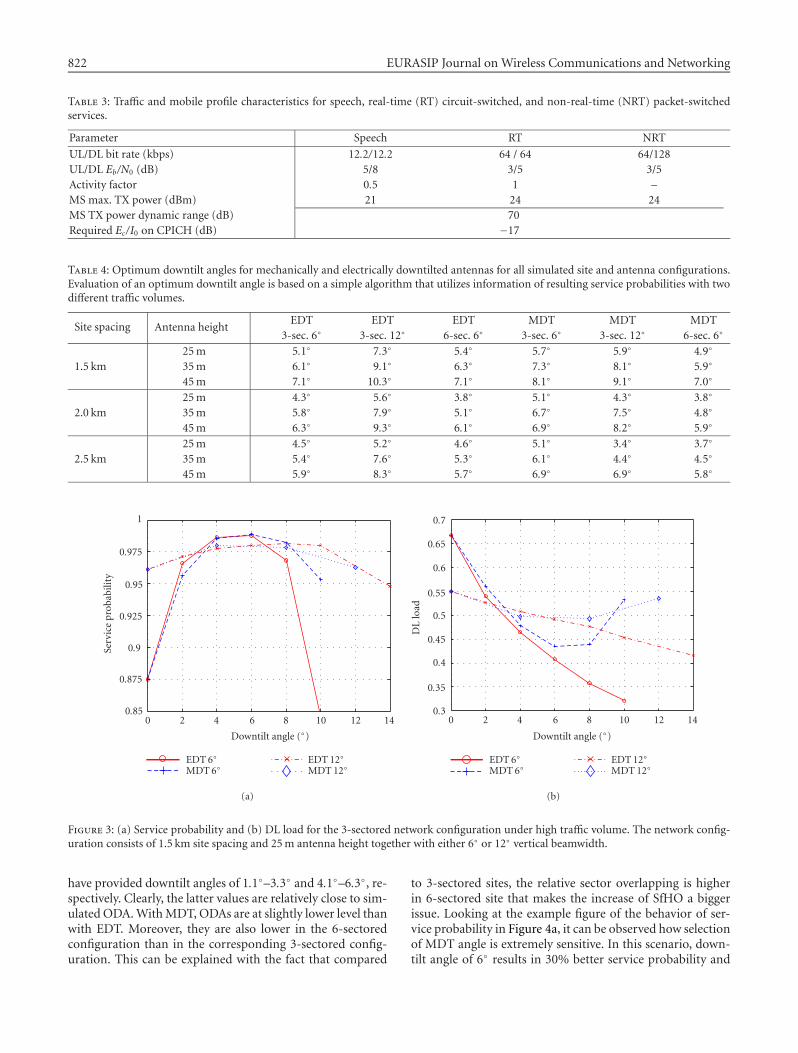
to 3-sectored sites, the relative sector overlapping is higherin 6-sectored site that makes the increase of SfHO a biggerissue. Looking at the example figure of the behavior of ser-vice probability in Figure 4a, it can be observed how selectionof MDT angle is extremely sensitive. In this scenario, down-tilt angle of 6◦ results in 30% better service probability and
Antenna Downtilt for WCDMA 823
0 2 4 6 8 100.6
0.65
0.7
0.75
0.8
0.85
0.9
0.95
1
EDT 6◦MDT6◦
Downtilt angle (◦)
Serviceprob
ability
(a)
0 2 4 6 8 100.2
0.3
0.4
0.5
0.6
0.7
0.8
0.9
1
EDT 6◦MDT6◦
Downtilt angle (◦)
DLload
(b)
Figure 4: (a) Service probability and (b) DL load for the 6-sectored network configuration with high traffic volume. The network configu-ration consists of 1.5 km site spacing and 25m antenna height together with 6◦ beamwidth.
45% lower DL load compared to 10◦ downtilt. The increaseof SfHO connections is strongly related to the shape of hor-izontal radiation pattern, and, for example, in [7] such hugeincrease was not observed due to utilization of an antennawith lower side-lobe level. For the 6-sectored EDT configu-ration, the selection of the downtilt angle has been observedto be slightly more sensitive with respect to site spacing andantenna height than for the corresponding 3-sectored con-figuration. This is caused by relatively larger coverage over-lapping (higher interference levels in the 6-sectored config-uration). According to the results, the selection of antennadowntilt angle in the 6-sectored sites can follow the selectedangles of the 3-sectored.
5.2. An empirical equation for selectionof downtilt angle
The geometrical factor in (7) and the geometrical angle in(8) underestimate typically the required downtilt angle, es-pecially with smaller site spacings and higher antenna posi-tions (i.e., with larger overlapping). Therefore, an empiricalequation is derived based on the simulated optimum down-tilt angles:
νopt = 3[ln(hBS)− d0.8
]log10
(θ−3dB
). (10)
Equation (10) relates the topological factors such as thebase station antenna height (hBS in meters), the intendedlength of the sector dominance area (d in kilometers),and the half-power vertical beamwidth (θ−3dB in degrees).The equation has been derived with a simple curve-fittingmethod. It provides a zero mean error with 0.5◦ standarddeviation with respect to simulated optimum downtilt an-gles for all simulated scenarios. As the error of (10) is rathersmall, it could be embedded into a radio network planning
tool. Thereafter, the tool would automatically provide a sug-gestion of downtilt angle for a planner based on the infor-mation of antenna vertical beamwidth, antenna height (alsoground height level could be utilized), and expected domi-nance area of particular sector.
5.3. UL TX power and SfHO analysis
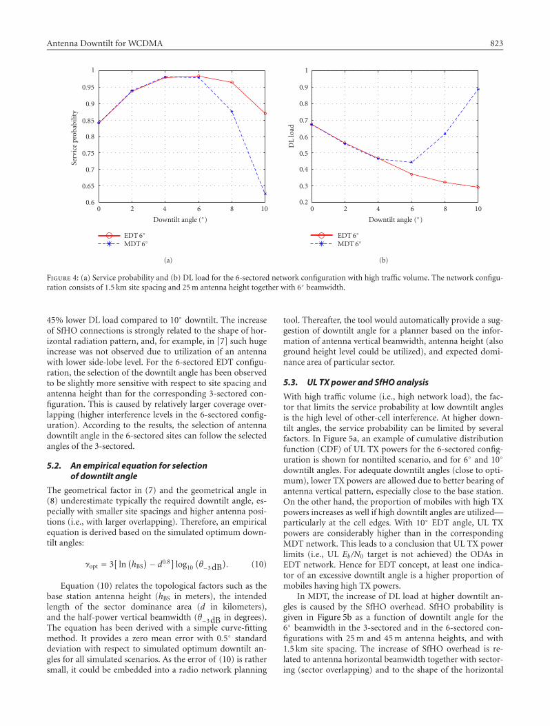
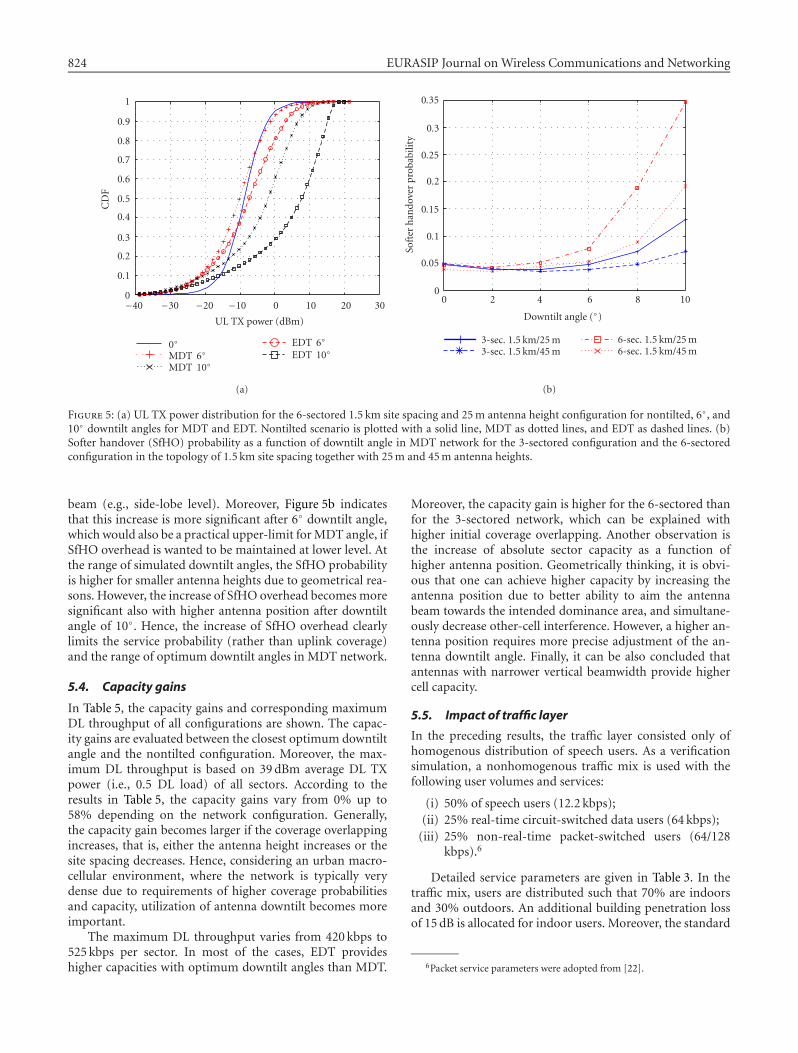
With high traffic volume (i.e., high network load), the fac-tor that limits the service probability at low downtilt anglesis the high level of other-cell interference. At higher down-tilt angles, the service probability can be limited by severalfactors. In Figure 5a, an example of cumulative distributionfunction (CDF) of UL TX powers for the 6-sectored config-uration is shown for nontilted scenario, and for 6◦ and 10◦
downtilt angles. For adequate downtilt angles (close to opti-mum), lower TX powers are allowed due to better bearing ofantenna vertical pattern, especially close to the base station.On the other hand, the proportion of mobiles with high TXpowers increases as well if high downtilt angles are utilized—particularly at the cell edges. With 10◦ EDT angle, UL TXpowers are considerably higher than in the correspondingMDT network. This leads to a conclusion that UL TX powerlimits (i.e., UL Eb/N0 target is not achieved) the ODAs inEDT network. Hence for EDT concept, at least one indica-tor of an excessive downtilt angle is a higher proportion ofmobiles having high TX powers.
In MDT, the increase of DL load at higher downtilt an-gles is caused by the SfHO overhead. SfHO probability isgiven in Figure 5b as a function of downtilt angle for the6◦ beamwidth in the 3-sectored and in the 6-sectored con-figurations with 25m and 45m antenna heights, and with1.5 km site spacing. The increase of SfHO overhead is re-lated to antenna horizontal beamwidth together with sector-ing (sector overlapping) and to the shape of the horizontal
824 EURASIP Journal on Wireless Communications and Networking
−40 −30 −20 −10 0 10 20 300
0.1
0.2
0.3
0.4
0.5
0.6
0.7
0.8
0.9
1
UL TX power (dBm)
CDF
0◦MDT 6◦MDT 10◦
EDT 6◦EDT 10◦
(a)
0 2 4 6 8 100
0.05
0.1
0.15
0.2
0.25
0.3
0.35
Downtilt angle (◦)
Softer
hando
verprob
ability
3-sec. 1.5 km/25m3-sec. 1.5 km/45m
6-sec. 1.5 km/25m6-sec. 1.5 km/45m
(b)
Figure 5: (a) UL TX power distribution for the 6-sectored 1.5 km site spacing and 25m antenna height configuration for nontilted, 6◦, and10◦ downtilt angles for MDT and EDT. Nontilted scenario is plotted with a solid line, MDT as dotted lines, and EDT as dashed lines. (b)Softer handover (SfHO) probability as a function of downtilt angle in MDT network for the 3-sectored configuration and the 6-sectoredconfiguration in the topology of 1.5 km site spacing together with 25m and 45m antenna heights.
beam (e.g., side-lobe level). Moreover, Figure 5b indicatesthat this increase is more significant after 6◦ downtilt angle,which would also be a practical upper-limit forMDT angle, ifSfHO overhead is wanted to be maintained at lower level. Atthe range of simulated downtilt angles, the SfHO probabilityis higher for smaller antenna heights due to geometrical rea-sons. However, the increase of SfHO overhead becomes moresignificant also with higher antenna position after downtiltangle of 10◦. Hence, the increase of SfHO overhead clearlylimits the service probability (rather than uplink coverage)and the range of optimum downtilt angles in MDT network.
5.4. Capacity gains
In Table 5, the capacity gains and corresponding maximumDL throughput of all configurations are shown. The capac-ity gains are evaluated between the closest optimum downtiltangle and the nontilted configuration. Moreover, the max-imum DL throughput is based on 39dBm average DL TXpower (i.e., 0.5 DL load) of all sectors. According to theresults in Table 5, the capacity gains vary from 0% up to58% depending on the network configuration. Generally,the capacity gain becomes larger if the coverage overlappingincreases, that is, either the antenna height increases or thesite spacing decreases. Hence, considering an urban macro-cellular environment, where the network is typically verydense due to requirements of higher coverage probabilitiesand capacity, utilization of antenna downtilt becomes moreimportant.
The maximum DL throughput varies from 420 kbps to525 kbps per sector. In most of the cases, EDT provideshigher capacities with optimum downtilt angles than MDT.
Moreover, the capacity gain is higher for the 6-sectored thanfor the 3-sectored network, which can be explained withhigher initial coverage overlapping. Another observation isthe increase of absolute sector capacity as a function ofhigher antenna position. Geometrically thinking, it is obvi-ous that one can achieve higher capacity by increasing theantenna position due to better ability to aim the antennabeam towards the intended dominance area, and simultane-ously decrease other-cell interference. However, a higher an-tenna position requires more precise adjustment of the an-tenna downtilt angle. Finally, it can be also concluded thatantennas with narrower vertical beamwidth provide highercell capacity.
5.5. Impact of traffic layer
In the preceding results, the traffic layer consisted only ofhomogenous distribution of speech users. As a verificationsimulation, a nonhomogenous traffic mix is used with thefollowing user volumes and services:
(i) 50% of speech users (12.2 kbps);(ii) 25% real-time circuit-switched data users (64 kbps);(iii) 25% non-real-time packet-switched users (64/128
kbps).6
Detailed service parameters are given in Table 3. In thetraffic mix, users are distributed such that 70% are indoorsand 30% outdoors. An additional building penetration lossof 15 dB is allocated for indoor users. Moreover, the standard
6Packet service parameters were adopted from [22].
Antenna Downtilt for WCDMA 825
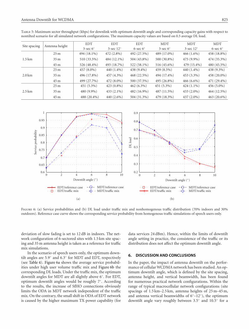
Table 5: Maximum sector throughput (kbps) for downlink with optimum downtilt angle and corresponding capacity gains with respect tonontilted scenario for all simulated network configurations. The maximum capacity values are based on 0.5 average DL load.
Site spacing Antenna heightEDT EDT EDT MDT MDT MDT
3-sec 6◦ 3-sec 12◦ 6-sec 6◦ 3-sec 6◦ 3-sec 12◦ 6-sec 6◦
25m 494 (18.1%) 472 (2.8%) 492 (27.5%) 489 (17.0%) 466 (1.6%) 458 (18.8%)
1.5 km 35m 510 (33.5%) 484 (12.1%) 504 (43.8%) 500 (30.8%) 475 (9.9%) 474 (35.3%)
45m 526 (48.4%) 493 (18.7%) 522 (58.1%) 516 (45.6%) 479 (15.4%) 480 (45.5%)25m 457 (8.0%) 440 (1.4%) 438 (9.4%) 459 (8.5%) 440 (1.4%) 438 (9.3%)
2.0 km 35m 496 (17.8%) 457 (4.3%) 468 (22.5%) 494 (17.4%) 453 (3.3%) 458 (20.0%)
45m 499 (27.7%) 472 (8.0%) 500 (37.5%) 495 (26.8%) 466 (6.6%) 471 (29.4%)25m 451 (5.3%) 423 (0.8%) 462 (6.3%) 451 (5.3%) 424 (1.1%) 456 (5.0%)
2.5 km 35m 480 (9.9%) 433 (2.1%) 482 (16.9%) 487 (11.5%) 433 (2.0%) 464 (12.5%)
45m 488 (20.4%) 440 (2.6%) 504 (31.3%) 479 (18.3%) 437 (2.0%) 463 (20.6%)
0 2 4 6 8 100.6
0.65
0.7
0.75
0.8
0.85
0.9
0.95
1
Downtilt angle (◦)
Serviceprob
ability
EDT/reference caseEDT/traffic mix
MDT/reference caseMDT/traffic mix
(a)
0 2 4 6 8 100.2
0.3
0.4
0.5
0.6
0.7
0.8
0.9
EDT/reference caseEDT/traffic mix
MDT/reference caseMDT/traffic mix
Downtilt angle (◦)
DLload
(b)
Figure 6: (a) Service probabilities and (b) DL load under traffic mix and nonhomogenous traffic distribution (70% indoors and 30%outdoors). Reference case curve shows the corresponding service probability from homogenous traffic simulations of speech users only.
deviation of slow fading is set to 12 dB in indoors. The net-work configuration of 6-sectored sites with 1.5 km site spac-ing and 35m antenna height is taken as a reference for trafficmix simulations.
In the scenario of speech users only, the optimum down-tilt angles are 5.9◦ and 6.3◦ for MDT and EDT, respectively(see Table 4). Figure 6a shows the average service probabil-ities under high user volume traffic mix and Figure 6b thecorresponding DL loads. Under the traffic mix, the optimumdowntilt angles for MDT are all slightly above 6◦. For EDT,optimum downtilt angles would be roughly 7◦. Accordingto the results, the increase of SfHO connections obviouslylimits the ODA in MDT network independent of the trafficmix. On the contrary, the small shift in ODA of EDT networkis caused by the higher maximum TX power capability (for
data services 24 dBm). Hence, within the limits of downtiltangle setting in practice, the consistence of the traffic or itsdistribution does not affect the optimum downtilt angle.
6. DISCUSSION AND CONCLUSIONS
In the paper, the impact of antenna downtilt on the perfor-mance of cellularWCDMAnetwork has been studied. An op-timum downtilt angle, which is defined by the site spacing,antenna height, and vertical beamwidth, has been foundfor numerous practical network configurations. Within therange of typical macrocellular network configurations (sitespacings of 1.5 km–2.5 km, antenna heights of 25m–45m,and antenna vertical beamwidths of 6◦–12◦), the optimumdowntilt angle vary roughly between 3.5◦ and 10.5◦ for a
826 EURASIP Journal on Wireless Communications and Networking
homogenous traffic distribution. The sectoring scheme (3-sectored or 6-sectored) and tilting concept (MDT or EDT)affect only in a smaller scale the selection of downtilt angle.
The behavior of EDT and MDT concepts from theWCDMA network performance point of view varies to someextent. In EDT, higher downtilt angles produce a greater pro-portion of mobile stations with high TX power that can easilylead to coverage problems. On the contrary in MDT, an ex-cessive downtilt angle can cause an increase of SfHO over-head. However, this phenomenon depends heavily on thecharacteristics of the antenna horizontal radiation patternand sectoring scheme. The increase of SfHO overhead is ob-viously one reason why the maximum DL sector capacitiesare smaller for MDT. However, the importance of antennadowntilt as a part of WCDMA topology optimization cannotbe argued as the observed capacity gains from downtiltingvary from 0% up to 58%. In general, capacity gain increaseswith higher antenna position and decreases with site spacing.Moreover, the narrower the antenna vertical beamwidth is,the higher the achievable capacity gain is. Also, the sensitiv-ity of the selection of downtilt angle varies, mostly accordingto the antenna vertical beamwidth.
In certain circumstances, SHO can provide gain againstthe fast fading. Due to the fact that no gain was providedfor a SHO connection, the observed capacity gain may beoverestimated in the sense that in the nontilted scenarios,the SHO overhead was considerably higher than in the opti-mally downtilted scenario. This would also mean larger pro-portion of mobiles benefitting from the SHO gain. On theother hand, for example, in [23], antenna downtilt has beenobserved to decrease the delay spread, which would in turnlead to an increase of code orthogonality and to an improve-ment of the downlink capacity.
The traffic distribution between outdoors and indoors ortraffic mix was not observed to have notable impact on theoptimum downtilt angle. However, as the optimum downtiltangle was searched as an average of two different traffic vol-umes, it is heavily assumed that the optimum downtilt angleis more sensitive to changes in the amount of users and theirlocation distribution within a cell. This proposes stronglyto concentrate on algorithms for adaptive electrical down-tilt schemes to further increase the capacity of WCDMA net-work.
ACKNOWLEDGMENT
This work was supported by the European CommunicationsEngineering (ECE) Ltd., Nokia Networks, FM Kartta, andNational Technology Agency of Finland.
REFERENCES
[1] D. J. Y. Lee and C. Xu, “Mechanical antenna downtilt and itsimpact on system design,” in Proc. IEEE 47th Vehicular Tech-nology Conference (VTC ’97), vol. 2, pp. 447–451, Phoenix,Ariz, USA, May 1997.
[2] J. Lempiainen andM.Manninen, Radio Interface System Plan-ning for GSM/GPRS/UMTS, Kluwer Academic, Dordrecht,The Netherlands, 2001.
[3] L. Zordan, N. Rutazihana, and N. Engelhart, “Capacity en-hancement of cellular mobile network using a dynamic elec-trical down-tilting antenna system,” in Proc. IEEE VTS 50thVehicular Technology Conference (VTC ’99), vol. 3, pp. 1915–1918, Amsterdam, The Netherlands, September 1999.
[4] I. Forkel, A. Kemper, R. Pabst, and R. Hermans, “The effect ofelectrical and mechanical antenna down-tilting in UMTS net-works,” in Proc. IEE 3rd International Conference on 3GMobileCommunication Technologies, pp. 86–90, London, UK, May2002.
[5] S. C. Bundy, “Antenna downtilt effects on CDMA cell-site ca-pacity,” in Proc. IEEE Radio and Wireless Conference (RAW-CON ’99), pp. 99–102, Denver, Colo, USA, August 1999.
[6] M. J. Nawrocki and T. W. Wieckowski, “Optimal site and an-tenna location for UMTS output results of 3G network simu-lation software,” in Proc. 14th International Conference on Mi-crowaves, Radar and Wireless Communications (MIKON ’02),vol. 3, pp. 890–893, Gdansk, Poland, May 2002.
[7] J. Niemela and J. Lempiainen, “Impact of mechanical antennadowntilt on performance of WCDMA cellular network,” inProc. IEEE 59th Vehicular Technology Conference (VTC ’04),vol. 4, pp. 2091–2095, Milan, Italy, May 2004.
[8] H.-S. Cho, Y.-I. Kim, and D. K. Sung, “Protection againstcochannel interference from neighboring cells using down-tilting of antenna beams,” in Proc. IEEE VTS 53rd Vehicu-lar Technology Conference (VTC ’01), vol. 3, pp. 1553–1557,Rhodes, Greece, May 2001.
[9] J.-S. Wu, J.-K. Chung, and C.-C. Wen, “Hot-spot traffic reliefwith a tilted antenna in CDMA cellular networks,” IEEE Trans.Vehicular Technology, vol. 47, no. 1, pp. 1–9, 1998.
[10] J. Laiho-Steffens, A. Wacker, and P. Aikio, “The impact ofthe radio network planning and site configuration on theWCDMA network capacity and quality of service,” in Proc.IEEE 51st Vehicular Technology Conference (VTC ’00), vol. 2,pp. 1006–1010, Tokyo, Japan, May 2000.
[11] A. Wacker, K. Sipila, and A. Kuurne, “Automated and re-motely optimization of antenna subsystem based on radionetwork performance,” in Proc. 5th International Symposiumon Wireless Personal Multimedia Communications (WPMC’02), vol. 2, pp. 752–756, Honolulu, Hawaii, USA, October2002.
[12] D. H. Kim, D. D. Lee, H. J. Kim, and K. C. Whang, “Capac-ity analysis of macro/microcellular CDMA with power ratiocontrol and tilted antenna,” IEEE Trans. Vehicular Technology,vol. 49, no. 1, pp. 34–42, 2000.
[13] M. Garcia-Lozano and S. Ruiz, “Effects of downtilting onRRM parameters,” in Proc. 15th IEEE International Sym-posium on Personal, Indoor and Mobile Radio Communica-tions (PIMRC ’04), vol. 3, pp. 2166–2170, Barcelona, Spain,September 2004.
[14] M. Pettersen, L. E. Braten, and A. G. Spilling, “Automatic an-tenna tilt control for capacity enhancement in UMTS FDD,”in Proc. IEEE 60th Vehicular Technology Conference (VTC ’04),vol. 1, pp. 280–284, Los Angeles, Calif, USA, September 2004.
[15] T. Isotalo, J. Niemela, and J. Lempiainen, “Electrical antennadowntilt in UMTS network,” in Proc. 5th European WirelessConference (EW ’04), pp. 265–271, Barcelona, Spain, February2004.
[16] J. Lempiainen and M. Manninen, Eds., UMTS Radio NetworkPlanning, Optimization and QoS Management, Kluwer Aca-demic, Dordrecht, The Netherlands, 2003.
[17] J. Niemela, “Impact of base station site and antenna configu-ration on capacity inWCDMA cellular networks,” M.S. thesis,Tampere University of Technology, Tampere, Finland, 2003.
[18] G. Wilson, “Electrical downtilt through beam-steering versusmechanical downtilt [base station antennas],” in Proc. IEEE
Antenna Downtilt for WCDMA 827
42nd Vehicular Technology Conference (VTC ’92), vol. 1, pp.1–4, Denver, Colo, USA, May 1992.
[19] Kathrein, Technical information and new products, 2004, avail-able at: http://www.kathrein.de/.
[20] Radio Frequency Systems, RFS, 2004, available at: http://www.rfsworld.com/.
[21] J. Wu and D. Yuan, “Antenna downtilt performance in urbanenvironments,” in Proc. IEEE Military Communications Con-ference (MILCOM ’96), vol. 3, pp. 739–744, McLean, Va, USA,October 1996.
[22] ETSI, “Selection procedures for the choice of radio transmis-sion technologies of the UMTS,” TR 101 112, V3.2.0.
[23] E. Benner and A. B. Sesay, “Effects of antenna height, antennagain, and pattern downtilting for cellular mobile radio,” IEEETrans. Vehicular Technology, vol. 45, no. 2, pp. 217–224, 1996.
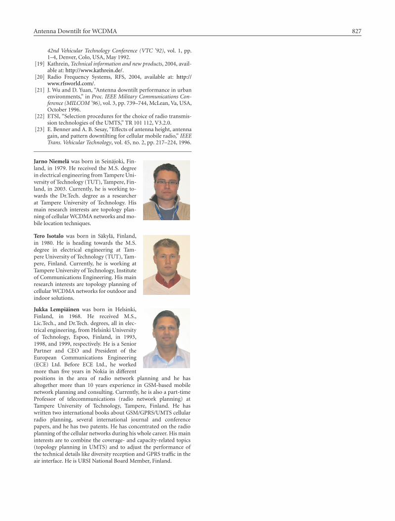
Jarno Niemela was born in Seinajoki, Fin-land, in 1979. He received the M.S. degreein electrical engineering fromTampere Uni-versity of Technology (TUT), Tampere, Fin-land, in 2003. Currently, he is working to-wards the Dr.Tech. degree as a researcherat Tampere University of Technology. Hismain research interests are topology plan-ning of cellularWCDMAnetworks andmo-bile location techniques.
Tero Isotalo was born in Sakyla, Finland,in 1980. He is heading towards the M.S.degree in electrical engineering at Tam-pere University of Technology (TUT), Tam-pere, Finland. Currently, he is working atTampere University of Technology, Instituteof Communications Engineering. His mainresearch interests are topology planning ofcellular WCDMA networks for outdoor andindoor solutions.
Jukka Lempiainen was born in Helsinki,Finland, in 1968. He received M.S.,Lic.Tech., and Dr.Tech. degrees, all in elec-trical engineering, from Helsinki Universityof Technology, Espoo, Finland, in 1993,1998, and 1999, respectively. He is a SeniorPartner and CEO and President of theEuropean Communications Engineering(ECE) Ltd. Before ECE Ltd., he workedmore than five years in Nokia in differentpositions in the area of radio network planning and he hasaltogether more than 10 years experience in GSM-based mobilenetwork planning and consulting. Currently, he is also a part-timeProfessor of telecommunications (radio network planning) atTampere University of Technology, Tampere, Finland. He haswritten two international books about GSM/GPRS/UMTS cellularradio planning, several international journal and conferencepapers, and he has two patents. He has concentrated on the radioplanning of the cellular networks during his whole career. His maininterests are to combine the coverage- and capacity-related topics(topology planning in UMTS) and to adjust the performance ofthe technical details like diversity reception and GPRS traffic in theair interface. He is URSI National Board Member, Finland.