options for brick veneer on mid-rise wood-frame buildings · options for brick veneer on . mid-rise...
TRANSCRIPT

Options for Brick Veneer on Mid-Rise Wood-Frame BuildingsR. Terry Malone, PE, SE • Senior Technical Director • WoodWorks
With growing interest in taller wood-frame buildings—many with five stories of wood on podiums and with wood-frame mezzanines—there has also been interest in the use of brick veneer at greater heights.
The 2015 International Building Code1 (IBC), Table 504.3, allows building heights up to 65 ft (19.8 m) for un-sprinklered Type III-A wood-frame buildings and up to 85 ft (25.9 m) if approved NFPA 13 sprinklers are used. For Type V-A wood-frame buildings, those heights can be 50 and 70 ft (15.2 and 21.3 m), respectively.
For designers interested in brick veneer as an exterior finish, some publications and design guides reference using steel studs and non-combustible supports. However, there are in fact code-compliant methods for using brick veneer over the entire height of a mid-rise wood-frame structure. Options include a prescriptive approach for the use of brick veneer up to 30 ft (9.14 m) in height and an alternative design approach for its use above 30 ft.
A recent publication by the Brick Industry Association2 gives direct guidance for the application of brick veneer on wood backing above the 30-ft prescriptive height limit. As this paper explains, one approach is to stack the brick veneer at full height off the foundation without shelf angles or intermediate support by the wood framing. Another is to support the brick veneer off shelf angles that are attached to the wood framing at desired intervals. Both of these approaches require the use of Section 12.2.1, Alternative design of anchored masonry veneer in the masonry code.3
Prescriptive requirements The masonry code prescriptive height limitations for brick veneer on wood construction allow veneer up to 30 ft (9.14 m) above the veneer support, which could be interpreted as a foundation or an alternate location of support. This is based on Section 12.2.2.3.1.2, which states:
12.2.2.3.1.2 Anchored veneer with a backing of wood framing shall not exceed 30 ft (9.14 m), or 38 ft (11.58 m) at a gable, in height above the location where the veneer is supported.
Emory Point • Atlanta, GA
Architects: Cooper Carry and
The Preston Partnership
Structural engineers: Ellinwood +
Machado LLC and Pruitt Eberly Stone Inc.
Completed: 2012
Emory point includes three buildings, one with five stories of Type III-A wood-frame construction over slab-on-grade, and two with four stories of Type V-A wood construction over a Type I-A post-tensioned concrete podium.
Pho
to: J
osh
Mei
ster
, co
urt
esy
Co
op
er C
arry
$FRA_410_BrickVeneer-SolutionPaper.indd 9 10/29/15 3:42 PM
2
However, this is followed by Section 12.2.2.3.1, which also requires that the weight of the veneer be supported on concrete or masonry foundations or some other non-combustible construction. In a wood-frame building, the steel shelf angle is often cited as this non-combustible support. Exceptions to 12.2.2.3.1 are noted in Sections:
• 12.2.2.3.1.1 – Supported by wood foundations
• 12.2.2.3.1.3 – Supported at each floor above the 30-ft (9.14-m) limit by non-combustible construction
• 12.2.2.3.1.4 – When used as an interior finish on wood framing, weighing 40 pounds per square foot (psf) (195 kg/m2) or less, and
• 12.2.2.3.1.5 – Supported at each floor by wood construction
Under prescriptive requirements of Section 12.2.2.3.1.3, the code says that, when anchored veneer exceeds 30 ft (9.14 m) or 38 ft (11.54 m) at a gable, in height above the location where the veneer is supported, the weight of the veneer can be supported by cold-formed steel studs at each story above the 30-ft (9.14-m) height limit. This prescriptive provision is the reason many code officials struggle with the use of wood-frame structures supporting brick veneer.
However, further inspection of Section 12.2.2.3.1.5 and its commentary reveals an exception to that prescriptive provision which explicitly allows veneer to be supported on and by wood construction provided the installed weight is 40 psf (195 kg/m2) or less and the supported height is equal to or less than 12 ft (3.7 m).
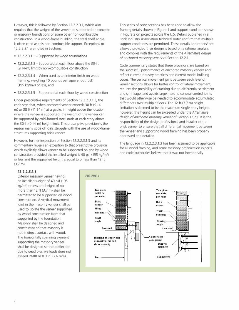
12.2.2.3.1.5 Exterior masonry veneer having an installed weight of 40 psf (195 kg/m2) or less and height of no more than 12 ft (3.7 m) shall be permitted to be supported on wood construction. A vertical movement joint in the masonry veneer shall be used to isolate the veneer supported by wood construction from that supported by the foundation. Masonry shall be designed and constructed so that masonry is not in direct contact with wood. The horizontally spanning element supporting the masonry veneer shall be designed so that deflection due to dead plus live loads does not exceed l/600 or 0.3 in. (7.6 mm).
This series of code sections has been used to allow the framing details shown in Figure 1 and support condition shown in Figure 2 on projects across the U.S. Details published in a Brick Industry Association technical note4 confirm that multiple support conditions are permitted. These details and others5 are allowed provided their design is based on a rational analysis and complies with the requirements of the Alternative design of anchored masonry veneer of Section 12.2.1.
Code commentary states that these provisions are based on the successful performance of anchored masonry veneer and reflect current industry practices and current model building codes. The vertical movement joint between each level of veneer sections allows for better control of lateral movement, reduces the possibility of cracking due to differential settlement and shrinkage, and avoids large, hard to conceal control joints that would otherwise be needed to accommodate accumulated differences over multiple floors. The 12-ft (3.7 m) height limitation is deemed to be the maximum single-story height; however, this height can be exceeded under the Alternative design of anchored masonry veneer of Section 12.2.1. It is the responsibility of the design professional and installer of the brick veneer to ensure that all differential movement between the veneer and supporting wood framing has been properly addressed and detailed.
The language in 12.2.2.3.1.3 has been assumed to be applicable for all wood framing, and some masonry organization experts and code authorities believe that it was not intentionally
FIGURE 1
$FRA_410_BrickVeneer-SolutionPaper.indd 2 10/29/15 3:42 PM

3
Alternative design requirementsCommon practice when exceeding the prescriptive 30-ft (9.14 m) height limitation for brick veneer on wood framing has been to follow Section 12.2.1 of the masonry code, Alternative design of anchored masonry veneer, which allows an alternate method to be used. This approach requires that the veneer support system be based on a rational engineered solution. Code commentary notes that there are no rational design provisions for anchored veneer stipulated in any code or standard. However, some guidance is provided in this document and in Designing Anchored Brick Veneer above 30 Ft with a Backing of Wood Framing published by the Brick Industry Association. The intent of Section 12.2.1 is to allow the designer to use alternative means of supporting and anchoring masonry veneer. Section 12.2.1 requirements are as follows:
a. The forces applied to the veneer are distributed through the veneer to the anchors and the backing using the principles of mechanics.
b. Out-of-plane deflection of the backing is limited to maintain the stability of the veneer.
c. The veneer is not subject to either the flexural tensile stress provisions of Section 8.2, or the nominal flexural tensile strength provisions of Section 9.1.9.2.
d. The veneer must meet the General veneer provisions Section 12.1, the prescriptive requirements for stack bond Section 12.2.2.9, and the prescriptive requirements for higher seismic areas Section 12.2.2.10.
excluded. Historically, light-frame wood construction has not typically been used for many buildings over 30 ft (9.14 m); its inclusion in the prescriptive code for this application may have been overlooked for that reason.
The prescriptive code requirements, as written, suggest that veneer over 30 ft (9.14 m) in height supported by wood construction can follow the same requirements of Section 12.2.2.3.1.3. However, it would require the use of Section 12.2.1, Alternative design of anchored masonry veneer.
Brick veneer applications exceeding 30 ft in height exist all over the country. One example of brick veneer applied on wood framing beyond the 30-ft (9.14-m) height limitation can be referenced in a WoodWorks case study of the University of Washington West Campus Student Housing6 project.
“The code allows you to go up 30 ft (9.14 m) [prescriptively] but we did not go that high,” said Chris Duvall, with structural engineering firm, Coughlin Porter Lundeen. “We isolated the brick panels at each level by using veneer ledger angles hung from the rim board at each floor above the podium. So, the first story of brick sits on top of the concrete foundation; it is re-supported at the concrete podium slab and then at every level of wood floor framing above. We then detailed the brick to allow the wood framing to shrink behind it while the brick veneer panel moves with the building.”
FIGURE 2
$FRA_410_BrickVeneer-SolutionPaper.indd 3 10/29/15 3:42 PM

4
FIGURE 3Conventional brick veneer According to Section 1.6 – Definitions of the masonry code, conventional brick veneer is plain unreinforced masonry (see Figure 3). Veneer is not allowed to be load bearing and only supports self-weight and out-of-plane loads. Out-of-plane bending loads are transferred through the masonry ties into the backing material or studs, where it is resisted. Section 12.2.1 (c) of the masonry code states that the veneer is not allowed to be subjected to the flexural tension stress provisions of Section 8.2 or Section 9.1.9.2. Contrary to Section 12.2.1(c), commentary states that the designer may choose not to consider stresses in the veneer or may limit the flexural stresses to ASD values, the anticipated cracking stress or some other limiting condition. Flexural tension stresses and cracking can be limited by controlling the deflection of the backing material. Current deflection limits for walls supporting brick veneer are subjective, with recommendations varying from L/240 to L/720, or greater, based on limiting the crack width.7 IBC prescribes a minimum of L/240 for brittle finishes. The Brick Industry Association recommends a limit of L/360.8
As part of the design, the designer should also consider the following:
• Provide horizontal in-plane, out-of-plane and vertical support for the veneer.
• Control deflection of the backing material.
• Allow for differential movement between the veneer and wood framing, including vertical shrinkage and lateral drift. See Figure 4.
• Develop anchor loads through the connections into the backing, providing adequate strength and stiffness.
Pho
to: C
lark
Bu
ilder
s G
rou
p
Advanced Individual Training Barracks with Company Operations Fort Lee, VA
Architect/design-build: LS3P Associates Ltd. and Clark Builders Group
Structural engineer: Michael M. Simpson & Associates Inc.
Completed: 2011
In this five-story Type III project, the first three stories of brick veneer were supported on the foundation; steel angle supports through-bolted to the wood framing were used to support brick at the fourth and fifth floor levels.
$FRA_410_BrickVeneer-SolutionPaper.indd 4 10/29/15 3:42 PM

5
• Account for water penetration expected through the brick veneer in the building envelope system.
• Account for air and vapor transmission expected through the brick veneer in the building envelope system.
Reinforced brick veneerReinforced brick veneer provides an alternate option for an exterior veneer system or cladding. A Western States Clay Products Publication9 states:
“The Structural Brick Veneer system is similar to conventional brick veneer except that the brick is reinforced to allow it to span further between ties and supports.”
This brick veneer system follows the definition in Section 1.6 in that it is non-load bearing and only supports self-weight and out-of-plane loads. It does not replace the wood-frame walls or lateral-resisting elements.
The structural brick veneer10 is hollow, similar to concrete masonry units (CMU blocks), which allows for the installation of vertical and horizontal reinforcement (see Figure 3). The veneer thus becomes a structural façade or cladding panel, which allows it to span beyond the 12-ft (3.7-m) limitation of Section 12.2.2.3.1.5. However, the 12-ft (3.7-m) floor-to-floor height is deemed the most practical with respect to connections and
Pho
to: B
enja
min
Ben
sch
nei
der
University of Washington West Campus Student Housing Phase One • Seattle, WA
Architect: Mahlum
Structural engineer: Coughlin Porter Lundeen
Phase one includes five buildings, each with five stories of Type VA wood-frame construction over a two-story concrete podium. Under the Seattle Building Code, Type VA wood buildings are permitted to be five stories.
handling. Reinforced brick eliminates the need for steel lintels at openings and also allows sloping window sills, brick soffits and precast concrete bands.
Pros: • Out-of-plane loads are resisted by the reinforced brick panels,
which span between floor levels, and are not transferred into the backing studs, thereby eliminating deflection limitation requirements of the backing studs. This places less demand on the studs, which can help reduce their size and/or spacing.
• Intermediate brick ties or anchors are reduced or eliminated. Out-of-plane loads are transferred directly into the floor diaphragms through the floor anchors and not the studs.
• Reinforcement helps reduce cracking and brick expansion due to temperature and moisture.
• The anchors at the floors are larger and therefore more resistant to heat.
• There is less thermal bridging through the ties because there are fewer ties or anchors.
• The panels can be fabricated on the ground, which could reduce the need for scaffolding.
Cons:• The reinforced brick units and reinforcing are more expensive.
• Additional coordination with the contractor is required.
• More detailing is required for the anchor connections.
Pho
to: B
enja
min
Ben
sch
nei
der
$FRA_410_BrickVeneer-SolutionPaper.indd 5 10/29/15 3:42 PM

6
on the type of framing (i.e., dimension vs. engineered wood, and platform vs. balloon framing), the number of wall plates involved in the wall section, and the difference in moisture content when the brick veneer is installed relative to the final moisture content after the building is fully enclosed from moisture exposure.
Design considerationsRegardless of the veneer type used, differential movement caused by shrinkage of the wood, expansion of the brick veneer and building drift must be accounted for and properly communicated and detailed on the drawings, especially at the eaves and at window and door openings. The wall elevation on the left side of Figure 4 shows the condition where shelf angles are not installed. Vertical expansion joints are often used at each floor level when utilizing conventional or reinforced brick as shown on the right side of Figure 4. This method allows for vertical movement at each floor level, and restricts the differential lateral movement to occur at each story minimizing the effects of drift. The commentary for Section 12.2.2.3 also states that the support does not need to occur at the floor level; it can occur at a window head/lintel or other convenient location as shown in Figure 5.
Section 2304.3.3 of the 2015 IBC, titled Shrinkage, states in part that wood walls and bearing partitions shall not support more than two floors and a roof unless an analysis satisfactory to the building official shows that shrinkage of the wood framing will not have adverse effects on the structure or any plumbing, electrical or mechanical systems. The greatest shrinkage in solid dimension lumber occurs in the cross-grain (tangential) direction. The shrinkage parallel to the grain (axially) is typically considered to be negligible. There have been several articles11 written on the subject, reporting from 3/8 in. (9.5 mm) to over 2 in. (50.8 mm) of total vertical movement depending on the precision of the analysis and what was considered in the review. The amount of shrinkage that can occur depends largely
FIGURE 5
FIGURE 4
$FRA_410_BrickVeneer-SolutionPaper.indd 6 10/29/15 3:42 PM
7
Additional vertical movement can occur from framing take-up caused when small framing gaps settle once the structure is fully loaded. Framing take-up and shrinkage has been estimated to be approximately 1/8-in. (3.17 mm) per floor and often occurs at perpendicular-to-grain bearing conditions. Designing Anchored Brick Veneer above 30 Ft (9.14 m) with a Backing of Wood Framing, published by the Brick Industry Association, also summarizes these shrinkage considerations.
Shrinkage in the wood framing can be reduced by considering one or more of the following:
• Use floor framing such as pre-engineered floor trusses/joists which may have less radial or tangential shrinkage.
• Minimize the number of wall plates by considering single wall top plates that are appropriately designed and detailed.
• Use kiln-dried (KD) or engineered wall plates to minimize the difference in moisture content differential between the time of installation and in-use condition.
• Consider semi-balloon framing where the floor joists are supported by hangers, avoiding the floor system contribution to the shrinkage.
• Avoid using additional plates as fillers.
Conclusion The masonry code, as it is written, does not prohibit the use of brick veneer exceeding the 30-ft (9.14 m) height limitation when supported by wood-frame backing. Two options generally exist. The designer can use the prescriptive method for the first 30 feet, then design the stories above that height using the alternate method, or design the entire height using the alternate method based on the results of the differential movement calculations. However, approval of the project and its successful completion requires justifying the design via rational analysis and the application of masonry code Section 12.2.1 and IBC Section 104.11. Brick veneer has been used successfully on many mid-rise wood-frame building projects.
References1 2015 International Building Code, International Code Council
2 12th North American Masonry Conference, Designing Anchored Brick Veneer above 30 Feet with a Backing of Wood Framing, Brick Industry Association, Charles B. Clark, Jr., Leroy Danforth, Jr., and Jim Bryja
3 Building Code Requirements for Masonry Structures, ACI 530-13/ASCE 5-13/TMS 402-13
4 Brick veneer/Wood Stud Walls, Technical Note TN-28, Brick Industry Association
5 Ibid (End Note 3)
6 University of Washington West Campus Student Housing, WoodWorks Case Study
7 Deflection limits for Wood Studs Backing Brick Veneer, Wood Design Focus Magazine, Fall 2007, Harold Sprague
8 Ibid (End Note 3); Analysis of the Behavior of Anchored Brick Veneer on Metal Stud Systems Subjected to Wind and Earthquake Forces, Computech Engineering Services, Berkeley, California, 1989, T. Kelly, M. Goodson, R. Mayes, and J. Asher
9 Design Guide for Structural Brick Veneer, Western States Clay Products Association, KPFF Consulting Engineers
10 Ibid (End Note 9)
11 Shrinkage Challenges with Mid-Rise Construction, Wood Design Focus V22, N.3, Michael Murphy, PE; Multi-story Wood-Frame Structures: Shrinkage Considerations and Calculations, Wood Design Focus V21, N.2, Richard Rummelhart, PE and Jeffery A. Fantozzi; Accommodating Movement in High-Rise Wood Frame Building Construction, Structure, June 2011, Richard W. Howe, PE; Volume Changes-Analysis and Effects of Movement, Technical Note TN-18, Brick Industry Association; Accommodating Expansion of Brick, Technical Note TN-1A, Brick Industry Association; Five-Story Wood-Frame Structure over Podium Slab, WoodWorks Design Example, D.S. Thompson
$FRA_410_BrickVeneer-SolutionPaper.indd 7 10/29/15 3:42 PM

8
Disclaimer: This paper is intended, not as a recommendation of brick veneer, but to clarify issues related to its use on wood framing. The information in this publication, including, without limitation, references to information contained in other publications or made available by other sources (collectively “information”) should not be used or relied upon for any application without competent professional examination and verification of its accuracy, suitability, code compliance and applicability by a licensed engineer, architect or other professional. Neither the Wood Products Council nor its employees, consultants, nor any other individuals or entities who contributed to the information make any warranty, representative or guarantee, expressed or implied, that the information is suitable for any general or particular use, that it is compliant with applicable law, codes or ordinances, or that it is free from infringement of any patent(s), nor do they assume any legal liability or responsibility for the use, application of and/or reference to the information. Anyone making use of the information in any manner assumes all liability arising from such use.
WW-WSP-05 • Options for Brick Veneer on Mid-Rise Wood-Frame Buildings • © 2015 WoodWorks
$FRA_410_BrickVeneer-SolutionPaper.indd 8 10/29/15 3:42 PM