options for calcium looping for co capture in the cement ... · pdf file2ikn gmbh, neustadt,...
TRANSCRIPT
Technology for a better society
1
G. Cinti1, R. Matai2, S. Becker2, M. Alonso3, C. Abanades3, M. Spinelli4, E De Lena4, S. Consonni4, M. Romano4, M. Hornberger5, R. Spörl5
1Italcementi, Bergamo, Italy 2IKN GmbH, Neustadt, Germany 3Agencia Estatal Consejo Superior de Investigaciones Cientificas (CSIC), Madrid, Spain 4Politecnico di Milano, Milan, Italy 5Institute of Combustion and Power Plant Technology (IFK), University of Stuttgart, Stuttgart, Germany
2nd ECRA/Cemcap workshop:
Carbon Capture Technologies in the Cement Industry
Dusseldorf, 6-7 November 2017
Options for calcium looping for CO2 capture in the cement industry
1

Technology for a better society
2
WP12 participants
Institute of Power Plant and Combustion technology, University of Stuttgart
Spanish research council, INCAR-CSIC
Italcementi
IKN,
Politecnico di Milano, Department of Energy

Technology for a better society
3
Calcium Looping process fundamentals
CARBONATION
CaO+CO2→CaCO3
~ 650ºC
Heat
Flue gas (CO2) (FCO2)
CO2-lean flue gas
CaCO3
CaO (FR)
CO2-rich gas to sequestration
CaCO3 make-up
(F0)
CaO purge
CALCINATION
CaCO3→CaO+CO2
~ 900ºC
Heat
Technology for a better society
4
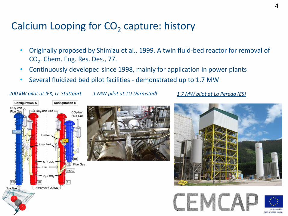
• Originally proposed by Shimizu et al., 1999. A twin fluid-bed reactor for removal of CO2. Chem. Eng. Res. Des., 77.
• Continuously developed since 1998, mainly for application in power plants
• Several fluidized bed pilot facilities - demonstrated up to 1.7 MW
Calcium Looping for CO2 capture: history
200 kW pilot at IFK, U. Stuttgart 1.7 MW pilot at La Pereda (ES) 1 MW pilot at TU Darmstadt

Technology for a better society
5
Calcium looping for cement plants
1. Cement plant-power plant coupling: CaO-rich spent sorbent from a CaL power plant as feed for the cement plant, as substitute of CaCO3
2. Post-combustion “tail end” configuration: CaL process is integrated in the cement plant with a conventional post-combustion capture configuration
3. Highly integrated CaL configuration: the CaL process is integrated within the cement production process by sharing the same oxyfuel calciner

Technology for a better society
6
Cement plant-power plant coupling
Bolier
coal
coal
CO2 lean
flue gas
FCO2
F0
clinker
raw meal
preheater
fuel
Calcined
raw meal

Technology for a better society
7
Cement plant-power plant coupling S
ubstitu
tion r
atio
(% o
f C
a fed t
o t
he c
em
ent
kiln
as C
aO
fro
m t
he p
ow
er
pla
nt)
Romano M.C. et al., 2013. The calcium looping process for low CO2 emission cement and power. Energy Procedia, 37, 7091-7099.
Technology for a better society
8
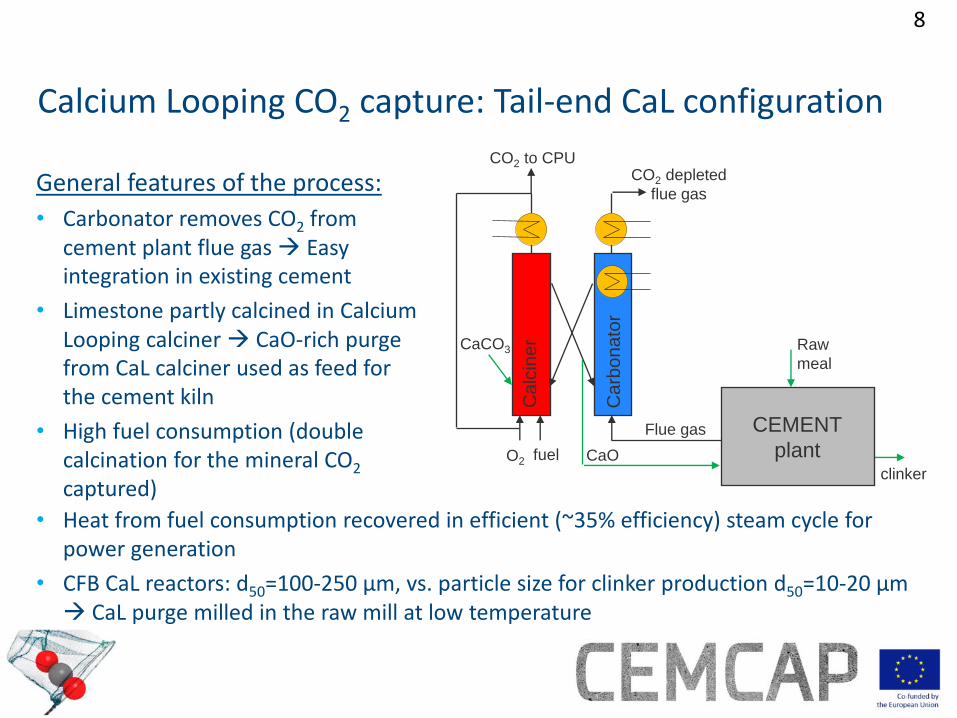
Calcium Looping CO2 capture: Tail-end CaL configuration
clinker
Ca
lcin
er CaCO3
fuel O2
Ca
rbo
na
tor
CO2 depleted
flue gas
CO2 to CPU
CEMENT
plant
Raw
meal
CaO
Flue gas
• Heat from fuel consumption recovered in efficient (~35% efficiency) steam cycle for power generation
• CFB CaL reactors: d50=100-250 μm, vs. particle size for clinker production d50=10-20 μm CaL purge milled in the raw mill at low temperature
General features of the process:
• Carbonator removes CO2 from cement plant flue gas Easy integration in existing cement
• Limestone partly calcined in Calcium Looping calciner CaO-rich purge from CaL calciner used as feed for the cement kiln
• High fuel consumption (double calcination for the mineral CO2 captured)
Technology for a better society
9
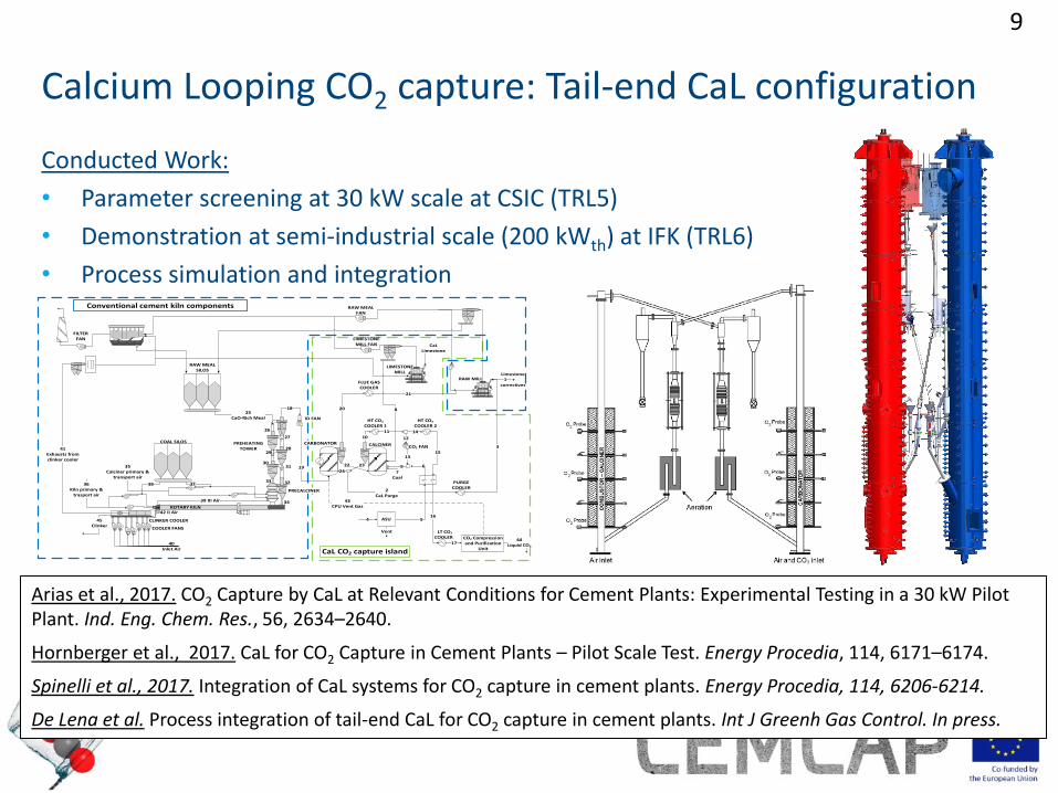
Conducted Work:
• Parameter screening at 30 kW scale at CSIC (TRL5)
• Demonstration at semi-industrial scale (200 kWth) at IFK (TRL6)
• Process simulation and integration
Arias et al., 2017. CO2 Capture by CaL at Relevant Conditions for Cement Plants: Experimental Testing in a 30 kW Pilot Plant. Ind. Eng. Chem. Res., 56, 2634–2640.
Hornberger et al., 2017. CaL for CO2 Capture in Cement Plants – Pilot Scale Test. Energy Procedia, 114, 6171–6174.
Spinelli et al., 2017. Integration of CaL systems for CO2 capture in cement plants. Energy Procedia, 114, 6206-6214.
De Lena et al. Process integration of tail-end CaL for CO2 capture in cement plants. Int J Greenh Gas Control. In press.
Calcium Looping CO2 capture: Tail-end CaL configuration
25 CaO-Rich Meal
18
39 III Air
RAW MILL
ROTARY KILN
CLINKER COOLER
40Inlet Air
COOLER FANS
Limestone +
correctives
20
19
10
11 14
12
1513
97
Coal
16
6
17
5ASU
22 23
24
2CaL Purge
CO2 Compression and Purification
Unit
CO2 FAN
HT CO2 COOLER 1
CALCINER
21
LT CO2
COOLER
3736Kiln primary &
trasport air
35Calciner primary &
transport air
3
PURGECOOLER
26
31
34
27
29
33
41Exhausts fromclinker cooler
28
30
32
PREHEATING TOWER
43CPU Vent Gas
44Liquid CO2
42 II Air
4
Vent
38
COAL SILOS
1
FILTER FAN
RAW MEAL FAN
RAW MEAL SILOS
45Clinker
FLUE GASCOOLER
HT CO2 COOLER 2
LIMESTONE MILL FAN
LIMESTONE MILL
8
CaL CO2 capture island
Conventional cement kiln components
PRECALCINER
ID FAN
CARBONATOR
CaLLimestone

Technology for a better society
10
Active space time design rule:
• τ𝑎𝑐𝑡𝑖𝑣𝑒 =𝑁𝐶𝑎𝑂
𝑁 𝐶𝑂2 𝑓𝑎 𝑋𝑎𝑣𝑒
• τ𝑎𝑐𝑡𝑖𝑣𝑒 > 501
𝑠 for 90 % CO2 capture
NCaO: molar amount of CaO in Carbonator ṄCO2
: molar flow of CO2 entering the Carbonator fa: sorbent fraction reacting in fast reaction regime Xave: average sorbent CO2 carrying capacity
Calcium Looping CO2 capture: Tail-end CaL configuration
Amount of active sorbent in the bed

Technology for a better society
11
Demonstration at semi-industrial scale:
• High CO2 capture up to 98 % demonstrated
• Favorable CaL operation conditions
• reduced recycle train
• high sorbent activity
• High CO2 capture at carbonator inlet may cause problems of entrainment due to reduction of fluidization gas (~ -25 %)
Calcium Looping CO2 capture: Tail-end CaL configuration
Technology for a better society
12
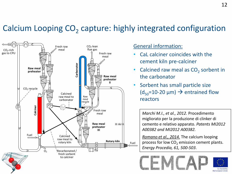
General information:
• CaL calciner coincides with the cement kiln pre-calciner
• Calcined raw meal as CO2 sorbent in the carbonator
• Sorbent has small particle size (d50=10-20 μm) entrained flow reactors
Calcium Looping CO2 capture: highly integrated configuration
Marchi M.I., et al., 2012. Procedimento migliorato per la produzione di clinker di cemento e relativo apparato. Patents MI2012 A00382 and MI2012 A00382.
Romano et al., 2014. The calcium looping process for low CO2 emission cement plants. Energy Procedia, 61, 500-503.
Fresh raw meal
Raw meal preheater
II
CO2-lean flue gas
Fuel
O2
Car
bon
ato
r
CO2-rich gas to CPU
Fuel
Cal
cine
r
Recarbonated / fresh sorbent
to calciner
Calcined raw meal to rotary kiln
Calcined raw meal to carbonator
Rotary kiln
CO2 recycle
Fresh raw meal
Raw meal preheater
III Air
Fresh raw meal
Raw meal preheater
III
Raw meal
recycle

Technology for a better society
13
Conducted Work:
• TGA – sorbent characterization
• (Re)carbonation experiment in EF conditions
• EF oxyfuel calcination experiments
• Simulation of entrained flow Calcium Looping
• Preliminary process integration study
0
0.1
0.2
0.3
0.4
0.5
0.6
0.7
0.8
0.9
1
0 20 40 60 80 100 120 140
CO
2ca
ptu
re e
ffic
ien
cy
Reactor length, m
Cooled Reactor
Adiabatic Reactor
15 kgsorbent/Nm3gas
10 kgsorbent/Nm3gas
5 kgsorbent/Nm3gas
Calcium Looping CO2 capture: highly integrated configuration
Technology for a better society
14
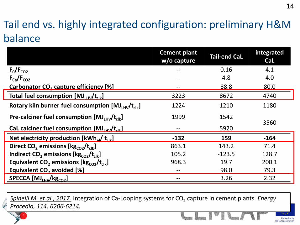
Tail end vs. highly integrated configuration: preliminary H&M balance
Cement plant w/o capture
Tail-end CaL integrated
CaL
F0/FCO2 -- 0.16 4.1
FCa/FCO2 -- 4.8 4.0
Carbonator CO2 capture efficiency [%] -- 88.8 80.0
Total fuel consumption [MJLHV/tclk] 3223 8672 4740
Rotary kiln burner fuel consumption [MJLHV/tclk] 1224 1210 1180
Pre-calciner fuel consumption [MJLHV/tclk] 1999 1542 3560
CaL calciner fuel consumption [MJLHV/tclk] -- 5920
Net electricity production [kWhel/ tclk] -132 159 -164
Direct CO2 emissions [kgCO2/tclk] 863.1 143.2 71.4
Indirect CO2 emissions [kgCO2/tclk] 105.2 -123.5 128.7
Equivalent CO2 emissions [kgCO2/tclk] 968.3 19.7 200.1
Equivalent CO2 avoided [%] -- 98.0 79.3
SPECCA [MJLHV/kgCO2] -- 3.26 2.32
Spinelli M. et al., 2017. Integration of Ca-Looping systems for CO2 capture in cement plants. Energy Procedia, 114, 6206-6214.

2nd ECRA/Cemcap workshop Dusseldorf, 6-7 November 2017
The CLEANKER project
G. Cintia, M. Fantinib, M. Romanoc, F. Canonicod, S. Consonnib,c
a Italcementi, Heidelberg Group b LEAP c Politecnico di Milano d Buzzi Unicem
Technology for a better society 16
Summary
The CLEANKER project
16
• Project objectives
• The demo plant
• The consortium
• Work packages
Technology for a better society 17
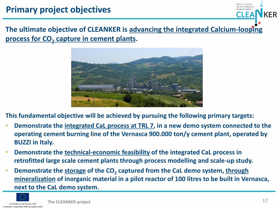
Primary project objectives
The CLEANKER project
17
The ultimate objective of CLEANKER is advancing the integrated Calcium-looping process for CO2 capture in cement plants.
This fundamental objective will be achieved by pursuing the following primary targets:
• Demonstrate the integrated CaL process at TRL 7, in a new demo system connected to the operating cement burning line of the Vernasca 900.000 ton/y cement plant, operated by BUZZI in Italy.
• Demonstrate the technical-economic feasibility of the integrated CaL process in retrofitted large scale cement plants through process modelling and scale-up study.
• Demonstrate the storage of the CO2 captured from the CaL demo system, through mineralization of inorganic material in a pilot reactor of 100 litres to be built in Vernasca, next to the CaL demo system.

Technology for a better society 18
Vernasca plant location
The CLEANKER project
18
VERNASCA PLANT

Technology for a better society 19
Primary project objectives
The CLEANKER project
19
• TRL 1 – basic principles observed
• TRL 2 – technology concept formulated
• TRL 3 – experimental proof of concept
• TRL 4 – technology validated in lab
• TRL 5 – technology validated in relevant environment (industrially relevant environment in the case of key enabling technologies)
• TRL 6 – technology demonstrated in relevant environment (industrially relevant environment in the case of key enabling technologies)
• TRL 7 – system prototype demonstration in operational environment
• TRL 8 – system complete and qualified
• TRL 9 – actual system proven in operational environment (competitive manufacturing in the case of key enabling technologies; or in space)

Technology for a better society 20
Indicative configuration of the CLEANKER pilot
The CLEANKER project
20
TO THE PROCESS FILTER
Temperature about 400°C
Temperature about 650°C
MEAL TO PREHEATER
GAS FROM PREHEATING TOWER
CO2 TO THE PROCESS FILTER
FUEL
OXYGEN
MEAL1 t/hTamb
MEAL TO PREHEATER
CO2
Entrained-flow oxyfuel calciner
Entrained-flow carbonator

Technology for a better society 21
Vernasca kiln preheater and rendering of CaL pilot
The CLEANKER project
21

Technology for a better society 22
The consortium
The CLEANKER project
22
5EU member states + Switzerland

Technology for a better society 23
Work packages
The CLEANKER project
23
WP3 – Demonstration of CaLprocess
WP4 – Comparative characterization of raw meals
for CaL
WP2 – Demonstration systemdesign
WP5 – Process integration and modelling
WP6 – Scale up, economics, LCA
WP8 – Exploitation
WP1 - Management
WP9 - Dissemination
WP7 – Transport and storage

Technology for a better society
24
Conclusions and Outlook
Ca-LOOPING PROCESS INTEGRATION OPTIONS: 1. Cement plant-power plant coupling:
• Excellent expected performance
• Easily retrofittable with low cost
• Logistic problem: a very large power plant has to be built next to the cement plant
2. Post-combustion capture configuration:
• Low uncertainty in the feasibility of the process (very similar to application in power plants)
• Very high CO2 capture expected
• Two calciners are present in the system, leading to high fuel consumptions
3. Integrated CaL configuration:
• High CO2 capture efficiency without modifying rotary kiln operation (no need of kiln oxyfiring).
• Higher thermal efficiency and lower fuel consumptions expected (compared to option 2)
• New carbonator design and fluid-dynamic regime: fluid-dynamics, heat management and sorbent performance need validation
Technology for a better society
25
Thank you for your attention!
Acknowledgement
This project has received funding from the European Union's Horizon 2020 research and innovation programme under grant agreements
n. 641185 (Cemcap) and n. 764816 (Cleanker)
www.sintef.no/cemcap
Twitter: @CEMCAP_CO2
Disclaimer: The European Commission support for the production of this publication does not constitute endorsement of the contents which reflects the views only of the authors, and the Commission cannot be held responsible for any use which may be made of the information contained therein