optiride electronically controlled air suspension (ecas
TRANSCRIPT
OPTIRIDE™ ELECTRONICALLY CONTROLLED AIR SUSPENSION (ECAS) FOR BUSES AND TRUCKS WITH CAN II
(SAE 1939)
MAINTENANCE MANUAL
MM1315cover.indd 1 7/9/2019 7:31:45 PM

Service Notes
Information contained in this publication was in effect at the time the publication was approved for printing and is subject to change without notice or liability. WABCO reserves the right to revise the information presented or to discontinue the production of parts described at any time.
WABCO Maintenance Manual MM-1315 (Revised 08-18)
About This ManualThis manual provides service and repair procedures for WABCO OptiRide™ Electronically Controlled Air Suspension (ECAS) for buses and trucks with CAN II (SAE 1939).
Before You Begin1. Read and understand all instructions and procedures before
you begin to service components.
2. Read and observe all Warning and Caution hazard alertmessages in this publication. They provide information that can help prevent serious personal injury, damage to components,or both.
3. Follow your company’s maintenance and service, installation,and diagnostics guidelines.
4. Use special tools when required to help avoid serious personalinjury and damage to components.
Hazard Alert Messages and Torque Symbols
WARNINGA Warning alerts you to an instruction or procedure that you must follow exactly to avoid serious personal injury and damage to components.
CAUTIONA Caution alerts you to an instruction or procedure that you must follow exactly to avoid damage to components.
@ This symbol alerts you to tighten fasteners to a specified torque value.
How to Obtain Additional Maintenance, Service and Product InformationVisit our Literature Center at wabco-na.com/literature to access and order additional information.
Contact WABCO North America Customer Care at 855-228-3203 (United States and Canada); 001-800-889-1834 (Mexico); or email [email protected].
WARNINGThis product can expose you to chemicals including Nickel, which is known to the State of California to cause cancer and birth defects or other reproductive harm. For more information, go to www.P65Warnings.ca.gov.
mm1315.bk.fm Page 2 Tuesday, July 9, 2019 7:23 PM

Contents
pg. pg.1 Section 1: IntroductionContentsOverview
2 Components3 Electronic Control Unit (ECU)
Height SensorPressure SensorsSolenoid Valve Block
4 Remote Control Unit (Optional)6 OptiRide™-Related Vehicle Lamps, Switches and Optional
Features
7 Section 2: Diagnostics, Troubleshooting and TestingGeneral InformationMaintenance InformationABS FaultsOptiRide™ FaultsPersonal Computer and Diagnostics Software ProgramDiagnostic Startup
8 Accessing Diagnostic Memory (Fault Codes)10 SPN SID FMI Fault Codes for OptiRide™ ECAS-CAN252 Setting Vehicle Suspension Height Levels (Calibration)
Vehicle Preparation24V Vehicle Height Calibration Procedure Using PC
Diagnostics54 12V Vehicle Height Calibration Procedure Using PC
Diagnostics55 Downloading Parameter and Calibration Settings from File
to ECAS ECU56 Testing Components and Circuits
Test Instructions
58 Section 3: Component ReplacementComponent Removal and InstallationECU ReplacementValve Block Replacement
59 Height Sensor Replacement60 Pressure Sensor Replacement
61 Section 4: System and Component DiagramsDiagramsECU Part Number 446 170 210 0 Connection Scheme for
Pressure Ratio62 ECU Part Number 446 170 210 0 Connection Scheme for
Pressure Equality63 ECU Part Number 446 170 300 0 Connection Scheme for
12-Volt Truck
64 ECU Part Number 446 170 300 0 Connection Scheme for 12-Volt Shuttle Bus (4x2)
65 ECU Part Number 446 170 300 0 Connection Scheme for 12-Volt Lift Axle Truck with ECAS 4 Valve
66 ECU Part Number 446 170 300 0 Connection Scheme for 12-Volt Lift Axle Truck with ECAS 3 Valve
67 ECU Part Number 446 170 300 0 Connection Scheme for 12-Volt Truck with ECAS 4 Valve
mm1315.bk.fm Page 3 Tuesday, July 9, 2019 7:23 PM

1 Introduction
1WABCO Maintenance Manual MM-1315 (Revised 08-18)
1 IntroductionHazard Alert MessagesRead and observe all Warning and Caution hazard alert messages in this publication. They provide information that can help prevent serious personal injury, damage to components, or both.
CAUTIONDue to the active standby feature on OptiRide™, disconnect the height sensor or disconnect the OptiRide™ ECU prior to replacing or working on OptiRide™ components.
ContentsThis manual contains service information for the WABCO OptiRide™ electronically controlled air suspension (ECAS) for buses and trucks with CAN II (SAE 1939) and with air suspensions.
The OptiRide™ system operates in conjunction with the WABCO anti-lock braking system (ABS). The OptiRide™ cannot function correctly without the ABS. The OptiRide™ system uses information from the ABS to determine vehicle speed and wheel slippage to adjust OptiRide™ operation accordingly.
NOTE: For testing and service information for a bus or truck ECAS without CAN II (SAE 1939), refer to Maintenance Manual 37, Electronically Controlled Air Suspension (ECAS) for Buses, for a bus system; or Maintenance Manual 36, Electronically Controlled Air Suspension (ECAS) for Trucks, for a truck system. If you cannot identify the OptiRide™ version installed on your vehicle, contact WABCO North America Customer Care at 855-228-3203.
OverviewThe WABCO OptiRide™ ECAS is an electrically controlled air suspension system designed to enhance the performance of the vehicle’s air suspension. OptiRide™ maintains an accurate leveling of the chassis height through the use of height sensors, electronic control unit (ECU) and solenoid valves. Because of the variety of suspension types and vehicle features, a particular set of parameters was developed for each vehicle type. These parameters determine some of the features and characteristics for the OptiRide™ configuration. In the event of a malfunction in the system, the OptiRide™ indicator lamp will alert the driver and the suspension will retain the existing air pressure in the air suspension bellows.
Some of the features provided by OptiRide™ include:
� Automatic Level Control — OptiRide™ continually monitors the vehicle’s height (axle-to-frame distances) through the ECU and the use of height and pressure sensors. When the height deviates from the preset nominal level, a correction is made quickly, exhausting or pressurizing the air suspension bellows by actuating solenoid valves. OptiRide™ will maintain the nominal vehicle level regardless of the road changes. There are pre-selected restrictions for when the height corrections can be made.
� Driver-Controlled Level Adjustment — Other than the nominal vehicle level, there can be additional levels selected by the driver to raise the vehicle for rough surfaces or lower vehicle height. These levels can be selected by switches on the vehicle dash panel. The driver can also return the vehicle to the nominal level with another dash panel switch (Recovery). There are pre-selected restrictions for when the height changes can be made.
� Vehicle Front Kneeling — This function, normally only on bus and coach, is also selected by the driver activating a switch on the vehicle dash panel, when the vehicle is stationary, and is used to facilitate the passenger entry and exit. Activating the KNEELING switch signals OptiRide™ to activate the front axle valve, exhausting air from the front bellows while maintaining the rear suspension at nominal level. This lowers the vehicle at the entry door step. There are pre-selected restrictions for when the kneeling function can be activated.
� Automatic Traction Help Load Transfer — When wheel slippage is detected by the vehicle’s ABS (due to slippery road surface conditions), a signal from the ABS triggers the OptiRide™ system. OptiRide™ can transfer weight from the non-drive axle (tag) to the vehicle’s drive axle by changing air pressures in the rear axles air suspension bellows. By transferring pressure from the tag axle to the drive axle air bellows, additional weight is transferred to the drive axle, increasing drive wheel traction. This function may also be initiated by the driver activating a switch on the vehicle dash panel. There are pre-selected restrictions for when the traction help can be activated and how much weight can be transferred.
OptiRide™ will continue to hold the transferred load until the preset limits of time or speed have been met, per the vehicle manufacturer settings.
mm1315.bk.fm Page 1 Tuesday, July 9, 2019 7:23 PM

1 Introduction
2 WABCO Maintenance Manual MM-1315 (Revised 08-18)
� Inclination Level Control (Pressure Equality) — The OptiRide™ ECU can adjust pressures in all air suspension bellows together or in individual air bellows. This allows OptiRide™ to compensate for inclinations caused by unbalanced loads or uneven road surfaces.
� OptiRide™ Height Change Requirements — OptiRide™ has several safety features to help ensure safe and correct level changes. Before OptiRide™ can automatically change vehicle heights, certain requirements, selected via BUS parameters, have to be met. For example, in order to make driver-selected height changes, the status of the doors, parking brake, transmission, vehicle speed and vehicle height may be considered. The requirements are determined by the OEM. Contact your vehicle OEM for further setting details.
ComponentsFigure 1.1 illustrates the major components of OptiRide™.
Figure 1.1
Figure 1.1
4010353a
STOP
M2
M1
mm1315.bk.fm Page 2 Tuesday, July 9, 2019 7:23 PM

1 Introduction
3WABCO Maintenance Manual MM-1315 (Revised 08-18)
Electronic Control Unit (ECU)The ECU is connected to the other OptiRide™ components, vehicle power, vehicle ground and CAN link through three different AMP connectors. Figure 1.2. The ECU has the following functions:
� Monitors up to four height sensors
� Monitors up to five pressure sensors
� Monitors sidewalk detector (optional)
� Monitors transverse accelerometer sensor (optional)
� Controls up to nine solenoid valves
� Communicates with CAN
� Controls vehicle indicator lamps (optional)
� Monitors function of system components, stores faults and performs diagnostics
Figure 1.2
Height SensorThe WABCO OptiRide™ height sensors are mounted to the vehicle chassis and connected by linkage to the axle housing providing the ECU with ride height information. The height sensor uses use a lever-type sensor housing that contains an inductive coil in which an armature moves inside the housing. The armature is connected to a lever which is attached to the axle by a linkage rod. When the distance between the chassis and the axle changes, the lever causes the armature to move within the coil, changing the analog signal produced by the sensor. The OptiRide™ ECU converts the analog sensor signal into digital numbers called “Timer Ticks” (TT) or “Counts”. Figure 1.3.
Figure 1.3
Pressure SensorsThe vehicle axle loads are determined by using pressure sensors attached to the suspension bellows. OptiRide™ may have pressure sensors on the front axle, the drive axle right and left and or any non-drive rear axle (tag axle) right and left. Figure 1.4.
Figure 1.4
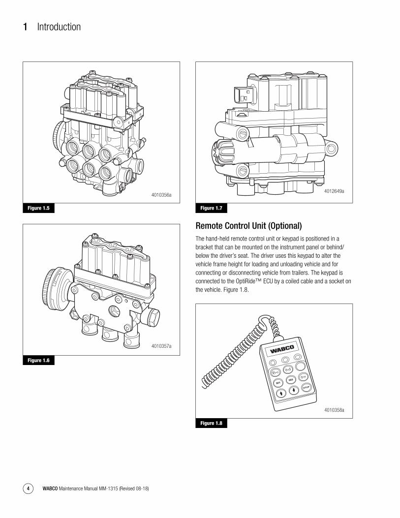
Solenoid Valve BlockSolenoid valve blocks have been developed for the OptiRide™ system. Several solenoid valves may be combined into one compact valve block. The solenoid valves control the air volume within the suspension air bellows by either increasing or decreasing the pressure as required by the ECU. Electrical connectors link the valve block to the ECU. Air ports connect the valve to air supply and to the suspension air bellows. The valve also has an exhaust port which is covered with a noise reduction device called a buffer. Figure 1.5, Figure 1.6 and Figure 1.7.
Figure 1.2
4010354a
Figure 1.3
Figure 1.4
4010363a
4006870a
27 FT-LB(36.6 Nm)TORQUE
mm1315.bk.fm Page 3 Tuesday, July 9, 2019 7:23 PM
1 Introduction
4 WABCO Maintenance Manual MM-1315 (Revised 08-18)
Figure 1.5
Figure 1.6
Figure 1.7
Remote Control Unit (Optional)The hand-held remote control unit or keypad is positioned in a bracket that can be mounted on the instrument panel or behind/below the driver’s seat. The driver uses this keypad to alter the vehicle frame height for loading and unloading vehicle and for connecting or disconnecting vehicle from trailers. The keypad is connected to the OptiRide™ ECU by a coiled cable and a socket on the vehicle. Figure 1.8.
Figure 1.8
Figure 1.5
Figure 1.6
4010356a
4010357a
Figure 1.7
Figure 1.8
4012649a
4010358a
STOP
M2
M1
mm1315.bk.fm Page 4 Tuesday, July 9, 2019 7:23 PM

1 Introduction
5WABCO Maintenance Manual MM-1315 (Revised 08-18)
Remote Control Operation
The hand-held remote control has several functions:
� Raising and lowering the vehicle suspension
� Returning vehicle to normal ride level
� Stopping all OptiRide™ functions
� Driver ability to preset and store up to two separate chassis heights
ON/OFF — Axle Selection Switch
Before the remote control unit can be used, the remote must be turned on. By pressing the rear axle selection key (center button top row), the remote control is activated and the remote is turned on. An acknowledgement lamp on the remote control indicates that the axle is selected and the unit is active. Pressing the key a second time will turn off the remote control unit and turn off the acknowledgement lamp.
Raising and Lowering Rear Suspension
The remote control unit allows the driver to change the vehicle’s rear suspension height within programmed limits. Pressing the up or down arrow keys cause the chassis height to be immediately altered. Releasing the key ends the height change. Remote control height changes can only be initiated while the vehicle is stationary or traveling at speeds less than the pre-selected parameters allow.
Normal Ride Height Level
Pressing the green Normal Ride Height Level key will immediately return the chassis to the pre-calibrated normal ride height level.
Setting and Selecting Memory Levels
By simultaneously pressing the STOP key and either the M1 or M2 memory keys, the current vehicle level will be stored as a memory height. Memory heights can only be stored while the vehicle is stationary. By pressing only the M1 or M2 memory keys, the chassis level is quickly adjusted to the stored memory height. The M1 or M2 height changes can only be initiated while the vehicle is stationary or at speeds less than 5 mph.
Stop Key
Pressing the STOP key discontinues all height control functions. This allows the driver to discontinue any manually activated height change which could be hazardous.
mm1315.bk.fm Page 5 Tuesday, July 9, 2019 7:23 PM

1 Introduction
6 WABCO Maintenance Manual MM-1315 (Revised 08-18)
OptiRide™-Related Vehicle Lamps, Switches and Optional FeaturesThe following tables describe most of the OptiRide™-related dash panel lamps and switches that could be installed in a vehicle.
Table A: Instrument Panel OptiRide™ 12V Tractor Lamps and Switches
Table B: Instrument Panel OptiRide™ 24V Bus Lamps and Switches
Lamps Switches Functionality
None Rear Rise or Up Arrow Raise rear suspension to pre-set height. Front suspension will remain at current level.
None Rear Lower or Down Arrow Lower rear suspension to pre-set height limit. Front suspension will remain at current level.
None Load Transfer/Momentary Switch Transfers air pressure from the non-drive axle (tag) to the vehicle’s drive axle.
OptiRide™ ECAS Fault or Red Lamp
None Indicates when system fault is active.
Ride Height or Amber Lamp
None Indicates when suspension level is outside of the normal ride height level.
Lamps Switches Functionality
Rear Rise Rear Rise or Up Arrow at back of vehicle Raise rear suspension to pre-set height. Front suspension will remain at current level.
Low Rise Level Control, Low Ride or Down Arrow at side of vehicle
Lower both front and rear suspension to minimum pre-set height limit.
High Rise Level Control, High Ride or Up Arrow at side of vehicle Raise both front and rear suspension to maximum pre-set height limit.
Kneel Kneel or Down Arrow at side of vehicle By holding switch, vehicle front will lower to kneeled position.
Kneel Normal Ride, Kneel Recover or UP/DOWN Arrow at side of vehicle
Will return suspension to normal pre-set ride height.
OptiRide™ ECAS Fault or Red Lamp
None Indicates when system fault is active.
Ride Fault or Amber Lamp
None Indicates when suspension level is outside of the Normal Ride Height Level.
None Economical Ride Enable/Disable Enables or disables economical ride features selected by vehicle manufacturer.
mm1315.bk.fm Page 6 Tuesday, July 9, 2019 7:23 PM

2 Diagnostics, Troubleshooting and Testing
7WABCO Maintenance Manual MM-1315 (Revised 08-18)
2 Diagnostics, Troubleshooting and TestingGeneral Information
Maintenance InformationThere is no regularly scheduled maintenance required for the WABCO OptiRide™ or ABS. However, OptiRide™ does not change current vehicle maintenance requirements.
ABS FaultsBefore performing any OptiRide™ diagnostics, make sure there are no ABS faults. Because of the interaction between the ABS and OptiRide™, a fault in the ABS may restrict the functionality of the OptiRide™ system. ABS faults can be diagnosed using the vehicle blink code or WABCO TOOLBOX™ Software.
OptiRide™ FaultsThe OptiRide™ Warning Lamp, mounted on the dash panel, indicates when OptiRide™ system faults are detected by the Electronic Control Unit (ECU) and stored in memory as active. If the fault is no longer active, the fault will be stored as inactive. OptiRide™ faults can be diagnosed using the WABCO TOOLBOX™ Software 11.0 or higher on a Personal Computer (PC). Refer to Personal Computer and Diagnostics Software Program in the section that describes using the software.
Personal Computer and Diagnostics Software ProgramThe WABCO OptiRide™ diagnostics software program runs in Windows 2000, NT, XP or Vista. If you have TOOLBOX™ Software with the OptiRide™ program installed on your computer, it may be used to:
� View current system status
� Retrieve and identify system faults
� Get on-screen repair instructions
� Illuminate lamps and activate certain outputs
� Calibrate the OptiRide™ system
� Raise and lower the suspension
� Test valve function and position
� View programmed vehicle parameters
The PC is connected to the vehicle’s SAE J1939 (Deutsch) diagnostic plug through special cables and a converter device. The diagnostic plug is wired to the vehicle’s data system that includes the OptiRide™ and ABS ECUs. In order to access the WABCO diagnostic software, the appropriate ECU and J1939 interface devices need to be selected.
Diagnostic Startup1. Connect the computer to the vehicle as follows. Attach the
J1939 interface device cable from your computer to the vehicle diagnostic port (9 pin Deutsch Connector). Turn the vehicle ignition switch ON. Figure 2.1 and Figure 2.2.
Figure 2.1
Figure 2.2
2. Select TOOLBOX™ Software from the desktop or from the Windows Start Menu, then click on the ECAS CAN II icon.
Figure 2.1
Figure 2.2
4010594a
4010611a
WABCO TOOLBOX 11.5
WABCO TOOLBOX
mm1315.bk.fm Page 7 Tuesday, July 9, 2019 7:23 PM
2 Diagnostics, Troubleshooting and Testing
8 WABCO Maintenance Manual MM-1315 (Revised 08-18)
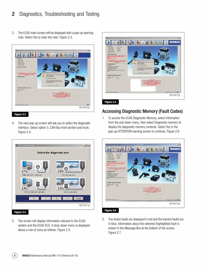
3. The ECAS main screen will be displayed with a pop-up warning note. Select Yes to clear the note. Figure 2.3.
Figure 2.3
4. The next pop-up screen will ask you to select the diagnostic interface. Select option 3, CAN Bus front section and truck. Figure 2.4.
Figure 2.4
5. The screen will display information relevant to the ECAS system and the ECAS ECU. A drop-down menu is displayed above a row of icons as follows. Figure 2.5.
Figure 2.5
Accessing Diagnostic Memory (Fault Codes)1. To access the ECAS Diagnostic Memory, select Information
from the pull-down menu, then select Diagnostic memory to display the diagnostic memory contents. Select Yes in the pop-up ATTENTION warning screen to continue. Figure 2.6.
Figure 2.6
2. The Active faults are displayed in red and the Inactive faults are in blue. Information about the selected (highlighted) fault is shown in the Message Box at the bottom of the screen. Figure 2.7.
Figure 2.3
Figure 2.4
4010410a
4010411a
Figure 2.5
Figure 2.6
4010412a
4010414a
mm1315.bk.fm Page 8 Tuesday, July 9, 2019 7:23 PM

2 Diagnostics, Troubleshooting and Testing
9WABCO Maintenance Manual MM-1315 (Revised 08-18)
Figure 2.7
3. The Inactive faults in blue can be cleared by selecting the Clear Diagnostic Memory tab. The Active faults have to be repaired before they can be cleared.
4. The Fault identifiers are listed in the Additional Information box on the bottom right of the screen. The first entry is the SID-marked path, the second is the FMI-marked type, the third entry is priority level and the fourth is the number of occurrences. The list of SID/FMI codes is shown below. Figure 2.8.
Figure 2.8
5. After the Inactive faults are cleared, select the OK tab, then the Cancel tab. This will permanently remove the Inactive faults from the ECU memory.
Figure 2.7
Figure 2.8
4010365a
4010366a
mm1315.bk.fm Page 9 Tuesday, July 9, 2019 7:23 PM

2 Diagnostics, Troubleshooting and Testing
10 WABCO Maintenance Manual MM-1315 (Revised 08-18)
SPN SID FMI Fault Codes for OptiRide™ ECAS-CAN2
Figure 2.9
Figure 2.912
V F
ault
SP
NS
IDF
MI
Des
crip
tio
nL
amp
Rea
ctio
nC
ause
Act
ion
/Ch
ecks
Co
ntr
ol U
nit
(E
CU
)
Inte
rnal
Fa
ult
2744
3025
42
Val
ue ju
mp/
Cha
ngin
g va
lues
or
inco
rrec
t val
ues
Red
Lam
p/C
heck
EC
AS
-
Am
ber
Lam
p/S
usp
Air
No
Aut
omat
ic
or M
anua
l F
unct
ion
Inte
rnal
Fau
lt
Ver
ify c
orre
ct p
ower
and
gro
und
read
ings
at t
he X
-1 c
onne
ctor
. Con
tact
W
AB
CO
Nor
th A
mer
ica
Cus
tom
er C
are
at 8
55-2
28-3
203
with
exa
ct
read
ings
. B
atte
ry V
olta
ge: K
ey O
n- X
1/10
– X
1/12
= 9
-16
volts
DC
.Ig
nitio
n V
olta
ge: K
ey O
ff- X
1/7
– X
1/12
= 9
-16
volts
DC
. G
roun
d R
esis
tanc
e: K
ey O
ff- X
1/12
- C
hass
is g
roun
d =
less
than
2 o
hms.
Inte
rnal
Fa
ult
2744
3025
411
Faul
t can
not b
e id
entifi
ed
Red
Lam
p/
Che
ck E
CA
S -
A
mbe
r La
mp/
Sus
p A
ir
No
Aut
omat
ic
or M
anua
l F
unct
ion
Inte
rnal
Fau
lt
Ver
ify c
orre
ct p
ower
and
gro
und
read
ings
at t
he X
-1 c
onne
ctor
. Con
tact
W
AB
CO
Nor
th A
mer
ica
Cus
tom
er C
are
at 8
55-2
28-3
203
with
exa
ct
read
ings
. B
atte
ry V
olta
ge: K
ey O
n- X
1/10
– X
1/12
= 9
-16
volts
DC
.Ig
nitio
n V
olta
ge: K
ey O
ff- X
1/7
– X
1/12
= 9
-16
volts
DC
. G
roun
d R
esis
tanc
e: K
ey O
ff- X
1/12
- C
hass
is g
roun
d =
less
than
2 o
hms.
Inte
rnal
Fa
ult
2744
3025
412
Faul
ty d
evic
e/co
mpo
nent
Red
Lam
p/
Che
ck E
CA
S -
A
mbe
r La
mp/
Sus
p A
ir
No
Aut
omat
ic
or M
anua
l F
unct
ion
Inte
rnal
Fau
lt
Ver
ify c
orre
ct p
ower
and
gro
und
read
ings
at t
he X
-1 c
onne
ctor
. Con
tact
W
AB
CO
Nor
th A
mer
ica
Cus
tom
er C
are
at 8
55-2
28-3
203
with
exa
ct
read
ings
. B
atte
ry V
olta
ge: K
ey O
n- X
1/10
– X
1/12
= 9
-16
volts
DC
.Ig
nitio
n V
olta
ge: K
ey O
ff- X
1/7
– X
1/12
= 9
-16
volts
DC
. G
roun
d R
esis
tanc
e: K
ey O
ff- X
1/12
- C
hass
is g
roun
d =
less
than
2 o
hms.
Che
cksu
m
EC
U-
Spe
cific
D
ata
Inco
rrec
t
2742
1438
2
Val
ue ju
mp/
Cha
ngin
g va
lues
or
inco
rrec
t val
ues
Red
Lam
p/
Che
ck E
CA
S -
A
mbe
r La
mp/
Sus
p A
ir
No
Aut
omat
ic
or M
anua
l F
unct
ion
Inco
rrec
t P
rogr
amm
ing
or C
alib
ratio
n
Che
cksu
m
Par
amet
ers
Inco
rrec
t27
4215
392
Val
ue ju
mp/
Cha
ngin
g va
lues
or
inco
rrec
t val
ues
Red
Lam
p/
Che
ck E
CA
S -
A
mbe
r La
mp/
Sus
p A
ir
No
Aut
omat
ic
or M
anua
l F
unct
ion
Inco
rrec
t P
rogr
amm
ing
or C
alib
ratio
n
Che
cksu
m
Cal
ibra
tion
Dat
a H
eigh
t S
enso
rs
Inco
rrec
t
2742
1640
2
Val
ue ju
mp/
Cha
ngin
g va
lues
or
inco
rrec
t val
ues
Red
Lam
p/
Che
ck E
CA
S -
A
mbe
r La
mp/
Sus
p A
ir
No
Aut
omat
ic
or M
anua
l F
unct
ion
Inco
rrec
t P
rogr
amm
ing
or C
alib
ratio
n
Re-
calib
rate
the
heig
ht s
enso
r w
ith T
OO
LBO
X™
Sof
twar
e. If
you
are
un
able
to s
ave
the
calib
ratio
n, fo
llow
the
diag
nost
ic s
teps
bel
ow.
Dis
conn
ect b
oth
the
X-2
and
X-3
con
nect
or a
t the
EC
U: K
ey O
ff-
Res
ista
nce
from
X2/
7 -
X2/
5 =
70-
110
ohm
s. If
the
read
ing
is o
ut o
f sp
ec, v
erify
cor
rect
res
ista
nce
at th
e he
ight
sen
sor.
With
X-2
and
X-3
di
scon
nect
ed, d
isco
nnec
t the
har
ness
at t
he h
eigh
t sen
sor
and
insp
ect
both
con
nect
or a
nd c
ompo
nent
for
dam
age,
con
tam
inat
ion
or c
orro
sion
. K
ey O
ff- A
cros
s pi
n 1
and
2 =
70-
110
ohm
s.
If th
e se
nsor
rea
ding
s ar
e co
rrec
t, is
olat
e th
e co
mpl
ete
heig
ht s
enso
r ci
rcui
t: K
ey O
ff- D
isco
nnec
t bot
h th
e X
-2 a
nd X
-3 c
onne
ctor
s at
the
EC
U,
then
dis
conn
ect b
oth
pres
sure
sen
sors
(he
ight
sen
sor
and
both
pre
ssur
e se
nsor
s di
scon
nect
ed),
insp
ect b
oth
conn
ecto
r an
d pr
essu
re s
enso
r fo
r da
mag
e, c
onta
min
atio
n or
cor
rosi
on.
K
ey O
ff- R
esis
tanc
e fr
om X
2/7
- X
2/1
= O
L --
> X
2/7
- X
2/5
= O
L --
> X
2/7
- X
2/6
= O
L --
> X
2/7
- X
3/3
= O
L --
> X
2/7
- C
hass
is g
roun
d =
OL
-->
X2/
1 -
Cha
ssis
gro
und
= O
L --
> X
2/5
- C
hass
is g
roun
d =
OL
-->
X2/
6 -
Cha
ssis
gr
ound
= O
L --
> X
3/3
- C
hass
is g
roun
d =
OL.
Dow
nloa
d .E
CU
file
from
the
EC
U a
nd c
onta
ct W
AB
CO
Nor
th A
mer
ica
Cus
tom
er C
are
at 8
55-2
28-3
203
or e
mai
l the
file
alo
ng w
ith a
pre
call
shee
t to
wna
cust
omer
care
@w
abco
-aut
o.co
m.
Dow
nloa
d .E
CU
file
from
the
EC
U a
nd c
onta
ct W
AB
CO
Nor
th A
mer
ica
Cus
tom
er C
are
at 8
55-2
28-3
203
or e
mai
l the
file
alo
ng w
ith a
pre
call
shee
t to
wna
cust
omer
care
@w
abco
-aut
o.co
m.
4012002a
mm1315.bk.fm Page 10 Tuesday, July 9, 2019 7:23 PM
2 Diagnostics, Troubleshooting and Testing
11WABCO Maintenance Manual MM-1315 (Revised 08-18)
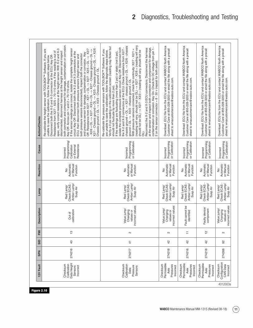
Figure 2.10
Figure 2.10
12V
Fau
ltS
PN
SID
FM
ID
escr
ipti
on
Lam
pR
eact
ion
Cau
seA
ctio
n/C
hec
ks
Che
cksu
m
Cal
ibra
tion
Dat
a H
eigh
t S
enso
rs
Inco
rrec
t
2742
1640
13O
ut o
f ca
libra
tion
Red
Lam
p/
Che
ck E
CA
S -
A
mbe
r La
mp/
Sus
p A
ir
No
Aut
omat
ic
or M
anua
l F
unct
ion
Inco
rrec
t P
rogr
amm
ing/
Cal
ibra
tion
or E
xter
nal
Res
ista
nce
Re-
calib
rate
the
heig
ht s
enso
r w
ith T
OO
LBO
X™
Sof
twar
e. If
you
are
un
able
to s
ave
the
calib
ratio
n, fo
llow
the
diag
nost
ic s
teps
bel
ow.
Dis
conn
ect b
oth
the
X-2
and
X-3
con
nect
or a
t the
EC
U: K
ey O
ff-
Res
ista
nce
from
X2/
7 -
X2/
5 =
70-
110
ohm
s. If
the
read
ing
is o
ut o
f sp
ec, v
erify
cor
rect
res
ista
nce
at th
e he
ight
sen
sor.
With
X-2
and
X-3
di
scon
nect
ed, d
isco
nnec
t har
ness
at t
he h
eigh
t sen
sor
and
insp
ect
both
con
nect
or a
nd c
ompo
nent
for
dam
age,
con
tam
inat
ion
or c
orro
sion
.K
ey O
ff- A
cros
s pi
n 1
and
2 =
70-
110
ohm
s.
If th
e se
nsor
rea
ding
s ar
e co
rrec
t, is
olat
e th
e co
mpl
ete
heig
ht s
enso
r ci
rcui
t: K
ey O
ff- D
isco
nnec
t bot
h th
e X
-2 a
nd X
-3 c
onne
ctor
s at
the
EC
U, t
hen
disc
onne
ct b
oth
pres
sure
sen
sors
(he
ight
sen
sor
and
both
pre
ssur
e se
nsor
s di
scon
nect
ed),
insp
ect b
oth
the
conn
ecto
r an
d pr
essu
re s
enso
r fo
r da
mag
e, c
onta
min
atio
n or
cor
rosi
on.
Key
O
ff- R
esis
tanc
e fr
om X
2/7
- X
2/1
= O
L --
> X
2/7
- X
2/5
= O
L --
> X
2/7
- X
2/6
= O
L --
> X
2/7
- X
3/3
= O
L --
> X
2/7
- C
hass
is g
roun
d =
OL
-->
X
2/1
- C
hass
is g
roun
d =
OL
-->
X2/
5 -
Cha
ssis
gro
und
= O
L --
> X
2/6
- C
hass
is g
roun
d =
OL
-->
X3/
3 -
Cha
ssis
gro
und
= O
L.
Che
cksu
m
Cal
ibra
tion
Dat
a P
ress
ure
Sen
sors
2742
1741
2
Val
ue ju
mp/
Cha
ngin
g va
lues
or
inco
rrec
t val
ues
Red
Lam
p/
Che
ck E
CA
S -
A
mbe
r La
mp/
Sus
p A
ir
No
Aut
omat
ic
or M
anua
l F
unct
ion
Inco
rrec
t P
rogr
amm
ing
or C
alib
ratio
n
Re-
calib
rate
the
pres
sure
sen
sors
with
TO
OLB
OX
™ S
oftw
are.
If y
ou
are
unab
le to
sav
e th
e ca
libra
tion,
follo
w th
e di
agno
stic
ste
ps b
elow
. V
erify
a 0
psi
rea
ding
on
the
calib
ratio
n sc
reen
(re
adin
g m
ay fl
icke
r bu
t sh
ould
not
fluc
tuat
e by
mor
e th
an 2
psi
). If
the
read
ings
are
fluc
tuat
ing
(mor
e th
an 2
psi
) or
sta
tic (
not 0
psi
),
isol
ate
the
com
plet
e pr
essu
re s
enso
r ci
rcui
t: K
ey O
ff- D
isco
nnec
t bot
h th
e X
-2 a
nd X
-3 c
onne
ctor
s at
the
EC
U. C
heck
res
ista
nce
from
X2/
7 -
chas
sis
grou
nd =
OL
-->
X2/
1 -
chas
sis
grou
nd =
OL
-->
X2/
6 -
chas
sis
grou
nd =
OL
-->
X3/
3 -
chas
sis
grou
nd =
OL
W
ith p
ress
ure
sens
ors
conn
ecte
d, c
heck
for
cont
inui
ty: X
2/7
- X
2/1
=
(rea
ding
will
var
y, s
houl
d no
t be
OL)
-->
X2/
7 -
X2/
6 =
(re
adin
g w
ill v
ary,
sh
ould
not
be
OL)
-->
X2/
7 -
X3/
3 =
(re
adin
g w
ill v
ary,
sho
uld
not b
e O
L).
Rec
onne
ct th
e X
-2 a
nd X
-3 E
CU
con
nect
ors.
Dis
conn
ect t
he h
arne
ss
at th
e se
nsor
and
insp
ect b
oth
conn
ecto
r an
d co
mpo
nent
for
dam
age,
co
ntam
inat
ion
or c
orro
sion
. Key
On-
Che
ck fo
r D
C v
olta
ge fr
om p
in 1
-
2 on
the
sens
or c
onne
ctor
= 8
- 3
0 v
(rep
eat f
or b
oth
axle
s).
Che
cksu
m
Per
mis
sibl
e A
xle
Pre
ssur
es
Inco
rrec
t
2742
1842
2
Val
ue ju
mp/
Cha
ngin
g va
lues
or
inco
rrec
t val
ues
Red
Lam
p/
Che
ck E
CA
S -
A
mbe
r La
mp/
Sus
p A
ir
No
Aut
omat
ic
or M
anua
l F
unct
ion
Inco
rrec
t P
rogr
amm
ing
or C
alib
ratio
n
Che
cksu
m
Per
mis
sibl
e A
xle
Pre
ssur
es
Inco
rrec
t
2742
1842
11Fa
ult c
anno
t be
iden
tified
Red
Lam
p/
Che
ck E
CA
S -
A
mbe
r La
mp/
Sus
p A
ir
No
Aut
omat
ic
or M
anua
l F
unct
ion
Inco
rrec
t P
rogr
amm
ing
or C
alib
ratio
n
Che
cksu
m
Per
mis
sibl
e A
xle
Pre
ssur
es
Inco
rrec
t
2742
1842
12Fa
ulty
dev
ice/
com
pone
nt
Red
Lam
p/
Che
ck E
CA
S -
A
mbe
r La
mp/
Sus
p A
ir
No
Aut
omat
ic
or M
anua
l F
unct
ion
Inco
rrec
t P
rogr
amm
ing
or C
alib
ratio
n
Che
cksu
m
Con
figur
atio
n C
AN
Dat
a In
corr
ect
2742
6892
2
Val
ue ju
mp/
Cha
ngin
g va
lues
or
inco
rrec
t val
ues
Red
Lam
p/
Che
ck E
CA
S -
A
mbe
r La
mp/
Sus
p A
ir
No
Aut
omat
ic
or M
anua
l F
unct
ion
Inco
rrec
t P
rogr
amm
ing
or C
alib
ratio
n
Dow
nloa
d .E
CU
file
from
the
EC
U a
nd c
onta
ct W
AB
CO
Nor
th A
mer
ica
Cus
tom
er C
are
at 8
55-2
28-3
203
or e
mai
l the
file
alo
ng w
ith a
pre
call
shee
t to
wna
cust
omer
care
@w
abco
-aut
o.co
m.
Dow
nloa
d .E
CU
file
from
the
EC
U a
nd c
onta
ct W
AB
CO
Nor
th A
mer
ica
Cus
tom
er C
are
at 8
55-2
28-3
203
or e
mai
l the
file
alo
ng w
ith a
pre
call
shee
t to
wna
cust
omer
care
@w
abco
-aut
o.co
m.
Dow
nloa
d .E
CU
file
from
the
EC
U a
nd c
onta
ct W
AB
CO
Nor
th A
mer
ica
Cus
tom
er C
are
at 8
55-2
28-3
203
or e
mai
l the
file
alo
ng w
ith a
pre
call
shee
t to
wna
cust
omer
care
@w
abco
-aut
o.co
m.
Dow
nloa
d .E
CU
file
from
the
EC
U a
nd c
onta
ct W
AB
CO
Nor
th A
mer
ica
Cus
tom
er C
are
at 8
55-2
28-3
203
or e
mai
l the
file
alo
ng w
ith a
pre
call
shee
t to
wna
cust
omer
care
@w
abco
-aut
o.co
m.
4012003a
mm1315.bk.fm Page 11 Tuesday, July 9, 2019 7:23 PM
2 Diagnostics, Troubleshooting and Testing
12 WABCO Maintenance Manual MM-1315 (Revised 08-18)
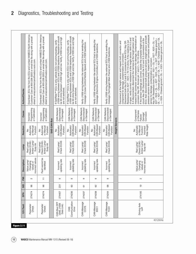
Figure 2.11
Figure 2.11
12V
Fau
ltS
PN
SID
FM
ID
escr
ipti
on
Lam
pR
eact
ion
Cau
seA
ctio
n/C
hec
ks
Par
amet
er
Che
ck27
4274
982
Val
ue ju
mp/
Cha
ngin
g va
lues
or
inco
rrec
t val
ues
Red
Lam
p/
Che
ck E
CA
S -
A
mbe
r La
mp/
Sus
p A
ir
No
Aut
omat
ic
or M
anua
l F
unct
ion
Inco
rrec
t P
rogr
amm
ing
or C
alib
ratio
n
Par
amet
er
Che
ck27
4274
9811
Faul
t can
not b
e id
entifi
ed
Red
Lam
p/
Che
ck E
CA
S -
A
mbe
r La
mp/
Sus
p A
ir
No
Aut
omat
ic
or M
anua
l F
unct
ion
Inco
rrec
t P
rogr
amm
ing
or C
alib
ratio
n
SA
E-C
AN
Bu
s
CA
N-B
us O
FF
(S
AE
J19
39
Dat
a Li
nk)
2744
0723
19
Inco
rrec
t up
datin
g ra
teR
ed L
amp/
C
heck
EC
AS
No
Aut
omat
ic/
CA
N-B
ased
F
unct
ion
CA
N N
etw
ork
Dis
conn
ecte
d or
Dam
aged
If O
ptiR
ide™
EC
U is
onl
y ve
hicl
e E
CU
not
com
mun
icat
ing,
ver
ify
J193
9 w
iring
bet
wee
n E
CU
and
J19
39 b
ackb
one.
Res
ista
nce
shou
ld
be 6
0 oh
ms
betw
een
J193
9 hi
gh a
nd lo
w. V
erify
J19
39 lo
w a
nd h
igh
are
not s
witc
hed.
CA
N
Com
mun
icat
ion
Err
or27
4236
609
Inco
rrec
t up
datin
g ra
teR
ed L
amp/
C
heck
EC
AS
No
Aut
omat
ic/
CA
N-B
ased
F
unct
ion
CA
N N
etw
ork
Dis
conn
ecte
d or
Dam
aged
If O
ptiR
ide™
EC
U is
onl
y ve
hicl
e E
CU
not
com
mun
icat
ing,
ver
ify
J193
9 w
iring
bet
wee
n E
CU
and
J19
39 b
ackb
one.
Res
ista
nce
shou
ld
be 6
0 oh
ms
betw
een
J193
9 hi
gh a
nd lo
w. V
erify
J19
39 lo
w a
nd h
igh
are
not s
witc
hed.
CA
N-M
essa
ge
CC
VS
2742
3761
9In
corr
ect
upda
ting
rate
Red
Lam
p/
Che
ck E
CA
S
No
Aut
omat
ic/
CA
N-B
ased
F
unct
ion
CA
N N
etw
ork
Dis
conn
ecte
d or
Dam
aged
Ver
ify J
1939
wiri
ng b
etw
een
the
exte
rnal
EC
U th
at is
sen
ding
the
mes
sage
(C
ruis
e C
ontr
ol/V
ehic
le S
peed
) an
d J1
939
back
bone
.
CA
N-M
essa
ge
EE
C1
2742
3862
9In
corr
ect
upda
ting
rate
Red
Lam
p/
Che
ck E
CA
S
No
Aut
omat
ic/
CA
N-B
ased
F
unct
ion
CA
N N
etw
ork
Dis
conn
ecte
d or
Dam
aged
Ver
ify J
1939
wiri
ng b
etw
een
the
exte
rnal
EC
U th
at is
sen
ding
the
mes
sage
(E
lect
roni
c E
ngin
e C
ontr
olle
r) a
nd J
1939
bac
kbon
e.
CA
N-M
essa
ge
TC
O1
2742
4468
9In
corr
ect
upda
ting
rate
Red
Lam
p/
Che
ck E
CA
S
No
Aut
omat
ic/
CA
N-B
ased
F
unct
ion
CA
N N
etw
ork
Dis
conn
ecte
d or
Dam
aged
Ver
ify J
1939
wiri
ng b
etw
een
the
exte
rnal
EC
U th
at is
sen
ding
the
mes
sage
(Ta
chog
raph
Mai
n Fr
ame)
and
J19
39 b
ackb
one.
Hei
gh
t S
enso
rs
Driv
ing
Axl
e Le
ft27
4195
192
Val
ue ju
mp/
Cha
ngin
g va
lues
or
inco
rrec
t val
ues
Red
Lam
p/
Che
ck E
CA
S -
A
mbe
r La
mp/
Sus
p A
ir
No
Aut
omat
ic
or M
anua
l F
unct
ion/
In
corr
ect
Rid
e H
eigh
t
Com
pone
nt
or H
arne
ss
Failu
re/
Dam
age/
C
orro
sion
Dis
conn
ect a
t the
hei
ght s
enso
r an
d in
spec
t bot
h co
nnec
tor
and
com
pone
nt fo
r da
mag
e, c
onta
min
atio
n or
cor
rosi
on.
Dis
conn
ect b
oth
the
X-2
and
X-3
con
nect
or a
t the
EC
U: K
ey O
ff-
Res
ista
nce
from
X2/
7 -
X2/
5 =
70-
110
ohm
s. If
the
read
ing
is o
ut
of s
pec,
ver
ify c
orre
ct r
esis
tanc
e at
the
heig
ht s
enso
r. W
ith X
-2 a
nd
X-3
dis
conn
ecte
d, d
isco
nnec
t the
har
ness
at t
he h
eigh
t sen
sor
and
insp
ect b
oth
conn
ecto
r an
d co
mpo
nent
for
dam
age,
con
tam
inat
ion
or
corr
osio
n: K
ey O
ff- A
cros
s pi
n 1
and
2 =
70-
110
ohm
s.
If th
e se
nsor
rea
ding
s ar
e co
rrec
t, is
olat
e th
e co
mpl
ete
heig
ht s
enso
r ci
rcui
t: K
ey O
ff- D
isco
nnec
t bot
h th
e X
-2 a
nd X
-3 c
onne
ctor
s at
the
EC
U, t
hen
disc
onne
ct b
oth
pres
sure
sen
sors
(he
ight
sen
sor
and
both
pr
essu
re s
enso
rs d
isco
nnec
ted)
, ins
pect
bot
h co
nnec
tor
and
pres
sure
se
nsor
for
dam
age,
con
tam
inat
ion
or c
orro
sion
.
Key
Off-
Res
ista
nce
from
X2/
7 -
X2/
1 =
OL
-->
X2/
7 -
X2/
5 =
OL
-->
X
2/7
- X
2/6
= O
L --
> X
2/7
- X
3/3
= O
L --
> X
2/7
- C
hass
is g
roun
d =
O
L --
> X
2/1
- C
hass
is g
roun
d =
OL
-->
X2/
5 -
Cha
ssis
gro
und
= O
L --
> X
2/6
- C
hass
is g
roun
d =
OL
-->
X3/
3 -
Cha
ssis
gro
und
= O
L.
Dow
nloa
d .E
CU
file
from
the
EC
U a
nd c
onta
ct W
AB
CO
Nor
th A
mer
ica
Cus
tom
er C
are
at 8
55-2
28-3
203
or e
mai
l the
file
alo
ng w
ith a
pre
call
shee
t to
wna
cust
omer
care
@w
abco
-aut
o.co
m.
Dow
nloa
d .E
CU
file
from
the
EC
U a
nd c
onta
ct W
AB
CO
Nor
th A
mer
ica
Cus
tom
er C
are
at 8
55-2
28-3
203
or e
mai
l the
file
alo
ng w
ith a
pre
call
shee
t to
wna
cust
omer
care
@w
abco
-aut
o.co
m.
4012004a
mm1315.bk.fm Page 12 Tuesday, July 9, 2019 7:23 PM

2 Diagnostics, Troubleshooting and Testing
13WABCO Maintenance Manual MM-1315 (Revised 08-18)
Figure 2.12
Figure 2.12
12V
Fau
ltS
PN
SID
FM
ID
escr
ipti
on
Lam
pR
eact
ion
Cau
seA
ctio
n/C
hec
ks
Driv
ing
Axl
e Le
ft27
4195
193
Ove
rvol
tage
or
shor
t circ
uit t
o +
Uba
tt
Red
Lam
p/
Che
ck E
CA
S -
A
mbe
r La
mp/
Sus
p A
ir
No
Aut
omat
ic
or M
anua
l F
unct
ion/
In
corr
ect
Rid
e H
eigh
t
Com
pone
nt
or H
arne
ss
Failu
re/
Dam
age/
C
orro
sion
Dis
conn
ect a
t the
hei
ght s
enso
r an
d in
spec
t bot
h co
nnec
tor
and
com
pone
nt fo
r da
mag
e, c
onta
min
atio
n or
cor
rosi
on.
Dis
conn
ect b
oth
the
X-2
and
X-3
con
nect
or a
t the
EC
U: K
ey O
ff-
Res
ista
nce
from
X2/
7 -
X2/
5 =
70-
110
ohm
s. If
the
read
ing
is o
ut
of s
pec,
ver
ify c
orre
ct r
esis
tanc
e at
the
heig
ht s
enso
r. W
ith X
-2 a
nd
X-3
dis
conn
ecte
d, d
isco
nnec
t the
har
ness
at t
he h
eigh
t sen
sor
and
insp
ect b
oth
conn
ecto
r an
d co
mpo
nent
for
dam
age,
con
tam
inat
ion
or
corr
osio
n: K
ey O
ff- A
cros
s pi
n 1
and
2 =
70-
110
ohm
s.
If th
e se
nsor
rea
ding
s ar
e co
rrec
t, is
olat
e th
e co
mpl
ete
heig
ht s
enso
r ci
rcui
t: K
ey O
ff- D
isco
nnec
t bot
h th
e X
-2 a
nd X
-3 c
onne
ctor
s at
the
EC
U, t
hen
disc
onne
ct b
oth
pres
sure
sen
sors
(he
ight
sen
sor
and
both
pr
essu
re s
enso
rs d
isco
nnec
ted)
, ins
pect
bot
h co
nnec
tor
and
pres
sure
se
nsor
for
dam
age,
con
tam
inat
ion
or c
orro
sion
.
Key
Off-
Res
ista
nce
from
X2/
7 -
X2/
1 =
OL
-->
X2/
7 -
X2/
5 =
OL
-->
X
2/7
- X
2/6
= O
L --
> X
2/7
- X
3/3
= O
L --
> X
2/7
- C
hass
is g
roun
d =
OL
-->
X2/
1 -
Cha
ssis
gro
und
= O
L --
> X
2/5
- C
hass
is g
roun
d =
OL
-->
X
2/6
- C
hass
is g
roun
d =
OL
-->
X3/
3 -
Cha
ssis
gro
und
= O
L.
Driv
ing
Axl
e Le
ft27
4195
195
Low
cur
rent
or
open
Red
Lam
p/
Che
ck E
CA
S -
A
mbe
r La
mp/
Sus
p A
ir
No
Aut
omat
ic
or M
anua
l F
unct
ion/
In
corr
ect
Rid
e H
eigh
t
Com
pone
nt
or H
arne
ss
Failu
re/
Dam
age/
C
orro
sion
Dis
conn
ect a
t the
hei
ght s
enso
r an
d in
spec
t bot
h co
nnec
tor
and
com
pone
nt fo
r da
mag
e, c
onta
min
atio
n or
cor
rosi
on.
Dis
conn
ect b
oth
the
X-2
and
X-3
con
nect
or a
t the
EC
U: K
ey O
ff-
Res
ista
nce
from
X2/
7 -
X2/
5 =
70-
110
ohm
s. If
the
read
ing
is o
ut
of s
pec,
ver
ify c
orre
ct r
esis
tanc
e at
the
heig
ht s
enso
r. W
ith X
-2 a
nd
X-3
dis
conn
ecte
d, d
isco
nnec
t the
har
ness
at t
he h
eigh
t sen
sor
and
insp
ect b
oth
conn
ecto
r an
d co
mpo
nent
for
dam
age,
con
tam
inat
ion
or
corr
osio
n: K
ey O
ff- A
cros
s pi
n 1
and
2 =
70-
110
ohm
s.
If th
e se
nsor
rea
ding
s ar
e co
rrec
t, is
olat
e th
e co
mpl
ete
heig
ht s
enso
r ci
rcui
t: K
ey O
ff- D
isco
nnec
t bot
h th
e X
-2 a
nd X
-3 c
onne
ctor
s at
the
EC
U, t
hen
disc
onne
ct b
oth
pres
sure
sen
sors
(he
ight
sen
sor
and
both
pr
essu
re s
enso
rs d
isco
nnec
ted)
, ins
pect
bot
h co
nnec
tor
and
pres
sure
se
nsor
for
dam
age,
con
tam
inat
ion
or c
orro
sion
.
Key
Off-
Res
ista
nce
from
X2/
7 -
X2/
1 =
OL
-->
X2/
7 -
X2/
5 =
OL
-->
X
2/7
- X
2/6
= O
L --
> X
2/7
- X
3/3
= O
L --
> X
2/7
- C
hass
is g
roun
d =
OL
-->
X2/
1 -
Cha
ssis
gro
und
= O
L --
> X
2/5
- C
hass
is g
roun
d =
OL
-->
X
2/6
- C
hass
is g
roun
d =
OL
-->
X3/
3 -
Cha
ssis
gro
und
= O
L.
Driv
ing
Axl
e Le
ft27
4195
196
Cur
rent
too
high
or
sho
rt c
ircui
t to
gro
und
Red
Lam
p/
Che
ck E
CA
S -
A
mbe
r La
mp/
Sus
p A
ir
No
Aut
omat
ic
or M
anua
l F
unct
ion/
In
corr
ect
Rid
e H
eigh
t
Com
pone
nt
or H
arne
ss
Failu
re/
Dam
age/
C
orro
sion
Dis
conn
ect a
t the
hei
ght s
enso
r an
d in
spec
t bot
h co
nnec
tor
and
com
pone
nt fo
r da
mag
e, c
onta
min
atio
n or
cor
rosi
on.
Dis
conn
ect b
oth
the
X-2
and
X-3
con
nect
or a
t the
EC
U: K
ey O
ff-
Res
ista
nce
from
X2/
7 -
X2/
5 =
70-
110
ohm
s. If
the
read
ing
is o
ut
of s
pec,
ver
ify c
orre
ct r
esis
tanc
e at
the
heig
ht s
enso
r. W
ith X
-2 a
nd
X-3
dis
conn
ecte
d, d
isco
nnec
t the
har
ness
at t
he h
eigh
t sen
sor
and
insp
ect b
oth
conn
ecto
r an
d co
mpo
nent
for
dam
age,
con
tam
inat
ion
or
corr
osio
n: K
ey O
ff- A
cros
s pi
n 1
and
2 =
70-
110
ohm
s.
If th
e se
nsor
rea
ding
s ar
e co
rrec
t, is
olat
e th
e co
mpl
ete
heig
ht s
enso
r ci
rcui
t: K
ey O
ff- D
isco
nnec
t bot
h th
e X
-2 a
nd X
-3 c
onne
ctor
s at
the
EC
U, t
hen
disc
onne
ct b
oth
pres
sure
sen
sors
(he
ight
sen
sor
and
both
pr
essu
re s
enso
rs d
isco
nnec
ted)
, ins
pect
bot
h co
nnec
tor
and
pres
sure
se
nsor
for
dam
age,
con
tam
inat
ion
or c
orro
sion
.
Key
Off-
Res
ista
nce
from
X2/
7 -
X2/
1 =
OL
-->
X2/
7 -
X2/
5 =
OL
-->
X
2/7
- X
2/6
= O
L --
> X
2/7
- X
3/3
= O
L --
> X
2/7
- C
hass
is g
roun
d =
OL
-->
X2/
1 -
Cha
ssis
gro
und
= O
L --
> X
2/5
- C
hass
is g
roun
d =
OL
-->
X
2/6
- C
hass
is g
roun
d =
OL
-->
X3/
3 -
Cha
ssis
gro
und
= O
L.
4012005a
mm1315.bk.fm Page 13 Tuesday, July 9, 2019 7:23 PM

2 Diagnostics, Troubleshooting and Testing
14 WABCO Maintenance Manual MM-1315 (Revised 08-18)
Figure 2.13
Figure 2.13
12V
Fau
ltS
PN
SID
FM
ID
escr
ipti
on
Lam
pR
eact
ion
Cau
seA
ctio
n/C
hec
ks
Pre
ssu
re S
enso
rs
Driv
ing
Axl
e Le
ft27
4201
253
Ove
rvol
tage
or
shor
t circ
uit t
o +
Uba
tt
Red
Lam
p/
Che
ck E
CA
S
Inco
rrec
t P
ress
ure
Rea
ding
/ O
ver
or
Und
er
Infla
tion
of
Air
Bag
Com
pone
nt
or H
arne
ss
Failu
re/
Dam
age/
C
orro
sion
Dis
conn
ect a
t the
sen
sor
and
insp
ect b
oth
conn
ecto
r an
d co
mpo
nent
fo
r da
mag
e, c
onta
min
atio
n or
cor
rosi
on.
Key
On-
Che
ck fo
r D
C v
olta
ge fr
om p
in 1
- 2
on
the
sens
or c
onne
ctor
=
8 -
30
v.
Key
Off-
Dis
conn
ect b
oth
pres
sure
sen
sors
and
dis
conn
ect b
oth
the
X-2
and
X-3
con
nect
ors
at th
e E
CU
che
ck r
esis
tanc
e fr
om X
2/7
- ch
assi
s gr
ound
= O
L --
> X
2/1
- ch
assi
s gr
ound
= O
L --
> X
2/6
- ch
assi
s gr
ound
= O
L.
Key
Off-
Che
ck X
2/7
- X
2/1
= O
L --
> X
2/7
- X
2/6
= O
L --
> X
2/1
- X
2/6
= O
L.
Driv
ing
Axl
e Le
ft27
4201
255
Low
cur
rent
or
open
Red
Lam
p/
Che
ck E
CA
S
Inco
rrec
t P
ress
ure
Rea
ding
/ O
ver
or
Und
er
Infla
tion
of
Air
Bag
Com
pone
nt
or H
arne
ss
Failu
re/
Dam
age/
C
orro
sion
Dis
conn
ect a
t the
sen
sor
and
insp
ect b
oth
conn
ecto
r an
d co
mpo
nent
fo
r da
mag
e, c
onta
min
atio
n or
cor
rosi
on.
Key
On-
Che
ck fo
r D
C v
olta
ge fr
om p
in 1
- 2
on
the
sens
or c
onne
ctor
=
8 -
30
v.
Key
Off-
Dis
conn
ect b
oth
pres
sure
sen
sors
and
dis
conn
ect b
oth
the
X-2
and
X-3
con
nect
ors
at th
e E
CU
che
ck r
esis
tanc
e fr
om X
2/7
- ch
assi
s gr
ound
= O
L --
> X
2/1
- ch
assi
s gr
ound
= O
L --
> X
2/6
- ch
assi
s gr
ound
= O
L.
Key
Off-
Che
ck X
2/7
- X
2/1
= O
L --
> X
2/7
- X
2/6
= O
L --
> X
2/1
- X
2/6
= O
L.
Driv
ing
Axl
e Le
ft27
4201
256
Cur
rent
too
high
or
sho
rt c
ircui
t to
gro
und
Red
Lam
p/
Che
ck E
CA
S
Inco
rrec
t P
ress
ure
Rea
ding
/ O
ver
or
Und
er
Infla
tion
of
Air
Bag
Com
pone
nt
or H
arne
ss
Failu
re/
Dam
age/
C
orro
sion
Dis
conn
ect a
t the
sen
sor
and
insp
ect b
oth
conn
ecto
r an
d co
mpo
nent
fo
r da
mag
e, c
onta
min
atio
n or
cor
rosi
on.
Key
On-
Che
ck fo
r D
C v
olta
ge fr
om p
in 1
- 2
on
the
sens
or c
onne
ctor
=
8 -
30
v.
Key
Off-
Dis
conn
ect b
oth
pres
sure
sen
sors
and
dis
conn
ect b
oth
the
X-2
and
X-3
con
nect
ors
at th
e E
CU
che
ck r
esis
tanc
e fr
om X
2/7
- ch
assi
s gr
ound
= O
L --
> X
2/1
- ch
assi
s gr
ound
= O
L --
> X
2/6
- ch
assi
s gr
ound
= O
L.
Key
Off-
Che
ck X
2/7
- X
2/1
= O
L --
> X
2/7
- X
2/6
= O
L --
> X
2/1
- X
2/6
= O
L.
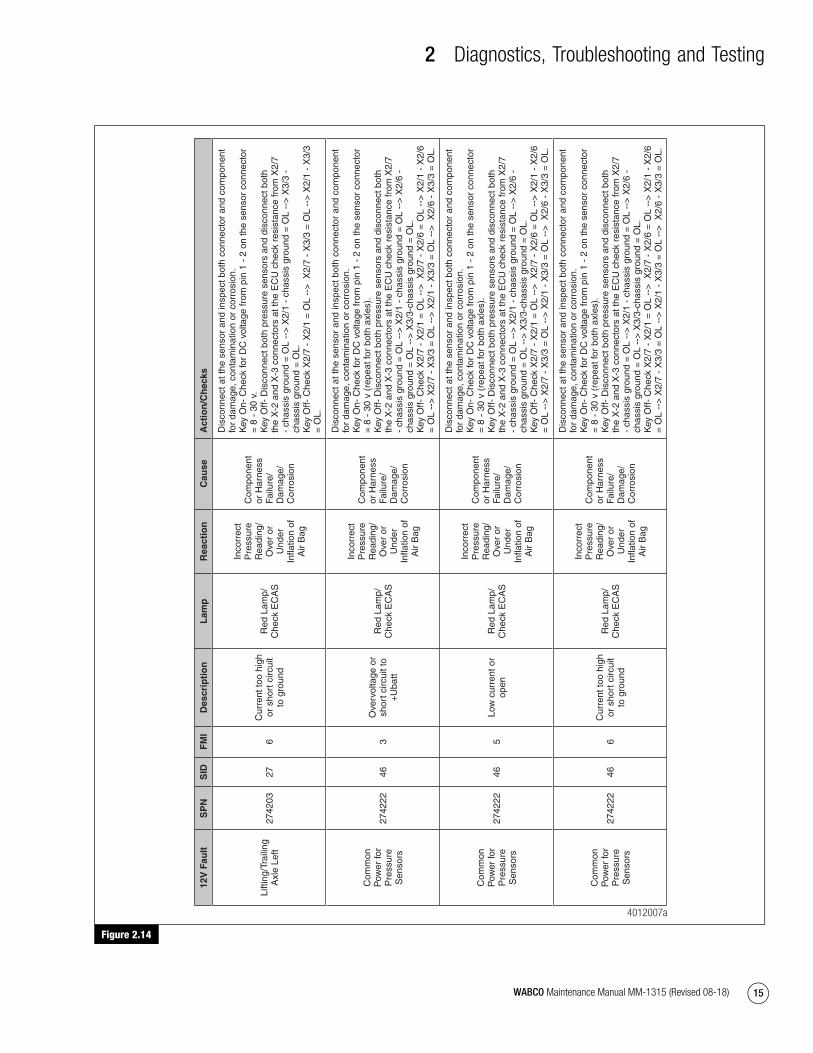
Lifti
ng/T
raili
ng
Axl
e Le
ft27
4203
273
Ove
rvol
tage
or
shor
t circ
uit t
o +
Uba
tt
Red
Lam
p/
Che
ck E
CA
S
Inco
rrec
t pr
essu
re
read
ing/
O
ver
or
Und
er
Infla
tion
of
Air
bag
Com
pone
nt
or H
arne
ss
Failu
re/
Dam
age/
C
orro
sion
Dis
conn
ect a
t the
sen
sor
and
insp
ect b
oth
conn
ecto
r an
d co
mpo
nent
fo
r da
mag
e, c
onta
min
atio
n or
cor
rosi
on.
Key
On-
Che
ck fo
r D
C v
olta
ge fr
om p
in 1
- 2
on
the
sens
or c
onne
ctor
=
8 -
30
v.
Key
Off-
Dis
conn
ect b
oth
pres
sure
sen
sors
and
dis
conn
ect b
oth
the
X-2
and
X-3
con
nect
ors
at th
e E
CU
che
ck r
esis
tanc
e fr
om X
2/7
- ch
assi
s gr
ound
= O
L --
> X
2/1
- ch
assi
s gr
ound
= O
L --
> X
3/3
- ch
assi
s gr
ound
= O
L.
Key
Off-
Che
ck X
2/7
- X
2/1
= O
L --
> X
2/7
- X
3/3
= O
L --
> X
2/1
- X
3/3
= O
L.
Lifti
ng/T
raili
ng
Axl
e Le
ft27
4203
275
Low
cur
rent
or
open
Red
Lam
p/
Che
ck E
CA
S
Inco
rrec
t pr
essu
re
read
ing/
O
ver
or
Und
er
Infla
tion
of
Air
bag
Com
pone
nt
or H
arne
ss
Failu
re/
Dam
age/
C
orro
sion
Dis
conn
ect a
t the
sen
sor
and
insp
ect b
oth
conn
ecto
r an
d co
mpo
nent
fo
r da
mag
e, c
onta
min
atio
n or
cor
rosi
on.
Key
On-
Che
ck fo
r D
C v
olta
ge fr
om p
in 1
- 2
on
the
sens
or c
onne
ctor
=
8 -
30
v.
Key
Off-
Dis
conn
ect b
oth
pres
sure
sen
sors
and
dis
conn
ect b
oth
the
X-2
and
X-3
con
nect
ors
at th
e E
CU
che
ck r
esis
tanc
e fr
om X
2/7
- ch
assi
s gr
ound
= O
L --
> X
2/1
- ch
assi
s gr
ound
= O
L --
> X
3/3
- ch
assi
s gr
ound
= O
L.
Key
Off-
Che
ck X
2/7
- X
2/1
= O
L --
> X
2/7
- X
3/3
= O
L --
> X
2/1
- X
3/3
= O
L.
4012006a
mm1315.bk.fm Page 14 Tuesday, July 9, 2019 7:23 PM
2 Diagnostics, Troubleshooting and Testing
15WABCO Maintenance Manual MM-1315 (Revised 08-18)
Figure 2.14
Figure 2.14
12V
Fau
ltS
PN
SID
FM
ID
escr
ipti
on
Lam
pR
eact
ion
Cau
seA
ctio
n/C
hec
ks
Lifti
ng/T
raili
ng
Axl
e Le
ft27
4203
276
Cur
rent
too
high
or
sho
rt c
ircui
t to
gro
und
Red
Lam
p/
Che
ck E
CA
S
Inco
rrec
t P
ress
ure
Rea
ding
/ O
ver
or
Und
er
Infla
tion
of
Air
Bag
Com
pone
nt
or H
arne
ss
Failu
re/
Dam
age/
C
orro
sion
Dis
conn
ect a
t the
sen
sor
and
insp
ect b
oth
conn
ecto
r an
d co
mpo
nent
fo
r da
mag
e, c
onta
min
atio
n or
cor
rosi
on.
Key
On-
Che
ck fo
r D
C v
olta
ge fr
om p
in 1
- 2
on
the
sens
or c
onne
ctor
=
8 -
30
v.
Key
Off-
Dis
conn
ect b
oth
pres
sure
sen
sors
and
dis
conn
ect b
oth
the
X-2
and
X-3
con
nect
ors
at th
e E
CU
che
ck r
esis
tanc
e fr
om X
2/7
- ch
assi
s gr
ound
= O
L --
> X
2/1
- ch
assi
s gr
ound
= O
L --
> X
3/3
- ch
assi
s gr
ound
= O
L.
Key
Off-
Che
ck X
2/7
- X
2/1
= O
L --
> X
2/7
- X
3/3
= O
L --
> X
2/1
- X
3/3
= O
L.
Com
mon
P
ower
for
Pre
ssur
e S
enso
rs
2742
2246
3O
verv
olta
ge o
r sh
ort c
ircui
t to
+U
batt
Red
Lam
p/
Che
ck E
CA
S
Inco
rrec
t P
ress
ure
Rea
ding
/ O
ver
or
Und
er
Infla
tion
of
Air
Bag
Com
pone
nt
or H
arne
ss
Failu
re/
Dam
age/
C
orro
sion
Dis
conn
ect a
t the
sen
sor
and
insp
ect b
oth
conn
ecto
r an
d co
mpo
nent
fo
r da
mag
e, c
onta
min
atio
n or
cor
rosi
on.
Key
On-
Che
ck fo
r D
C v
olta
ge fr
om p
in 1
- 2
on
the
sens
or c
onne
ctor
=
8 -
30
v (r
epea
t for
bot
h ax
les)
. K
ey O
ff- D
isco
nnec
t bot
h pr
essu
re s
enso
rs a
nd d
isco
nnec
t bot
h th
e X
-2 a
nd X
-3 c
onne
ctor
s at
the
EC
U c
heck
res
ista
nce
from
X2/
7 -
chas
sis
grou
nd =
OL
-->
X2/
1 -
chas
sis
grou
nd =
OL
-->
X2/
6 -
chas
sis
grou
nd =
OL
-->
X3/
3-ch
assi
s gr
ound
= O
L.
Key
Off-
Che
ck X
2/7
- X
2/1
= O
L --
> X
2/7
- X
2/6
= O
L --
> X
2/1
- X
2/6
= O
L --
> X
2/7
- X
3/3
= O
L --
> X
2/1
- X
3/3
= O
L --
> X
2/6
- X
3/3
= O
L.
Com
mon
P
ower
for
Pre
ssur
e S
enso
rs
2742
2246
5Lo
w c
urre
nt o
r op
enR
ed L
amp/
C
heck
EC
AS
Inco
rrec
t P
ress
ure
Rea
ding
/ O
ver
or
Und
er
Infla
tion
of
Air
Bag
Com
pone
nt
or H
arne
ss
Failu
re/
Dam
age/
C
orro
sion
Dis
conn
ect a
t the
sen
sor
and
insp
ect b
oth
conn
ecto
r an
d co
mpo
nent
fo
r da
mag
e, c
onta
min
atio
n or
cor
rosi
on.
Key
On-
Che
ck fo
r D
C v
olta
ge fr
om p
in 1
- 2
on
the
sens
or c
onne
ctor
=
8 -
30
v (r
epea
t for
bot
h ax
les)
. K
ey O
ff- D
isco
nnec
t bot
h pr
essu
re s
enso
rs a
nd d
isco
nnec
t bot
h th
e X
-2 a
nd X
-3 c
onne
ctor
s at
the
EC
U c
heck
res
ista
nce
from
X2/
7 -
chas
sis
grou
nd =
OL
-->
X2/
1 -
chas
sis
grou
nd =
OL
-->
X2/
6 -
chas
sis
grou
nd =
OL
-->
X3/
3-ch
assi
s gr
ound
= O
L.
Key
Off-
Che
ck X
2/7
- X
2/1
= O
L --
> X
2/7
- X
2/6
= O
L --
> X
2/1
- X
2/6
= O
L --
> X
2/7
- X
3/3
= O
L --
> X
2/1
- X
3/3
= O
L --
> X
2/6
- X
3/3
= O
L.
Com
mon
P
ower
for
Pre
ssur
e S
enso
rs
2742
2246
6C
urre
nt to
o hi
gh
or s
hort
circ
uit
to g
roun
d
Red
Lam
p/
Che
ck E
CA
S
Inco
rrec
t P
ress
ure
Rea
ding
/ O
ver
or
Und
er
Infla
tion
of
Air
Bag
Com
pone
nt
or H
arne
ss
Failu
re/
Dam
age/
C
orro
sion
Dis
conn
ect a
t the
sen
sor
and
insp
ect b
oth
conn
ecto
r an
d co
mpo
nent
fo
r da
mag
e, c
onta
min
atio
n or
cor
rosi
on.
Key
On-
Che
ck fo
r D
C v
olta
ge fr
om p
in 1
- 2
on
the
sens
or c
onne
ctor
=
8 -
30
v (r
epea
t for
bot
h ax
les)
. K
ey O
ff- D
isco
nnec
t bot
h pr
essu
re s
enso
rs a
nd d
isco
nnec
t bot
h th
e X
-2 a
nd X
-3 c
onne
ctor
s at
the
EC
U c
heck
res
ista
nce
from
X2/
7 -
chas
sis
grou
nd =
OL
-->
X2/
1 -
chas
sis
grou
nd =
OL
-->
X2/
6 -
chas
sis
grou
nd =
OL
-->
X3/
3-ch
assi
s gr
ound
= O
L.
Key
Off-
Che
ck X
2/7
- X
2/1
= O
L --
> X
2/7
- X
2/6
= O
L --
> X
2/1
- X
2/6
= O
L --
> X
2/7
- X
3/3
= O
L --
> X
2/1
- X
3/3
= O
L --
> X
2/6
- X
3/3
= O
L.
4012007a
mm1315.bk.fm Page 15 Tuesday, July 9, 2019 7:23 PM
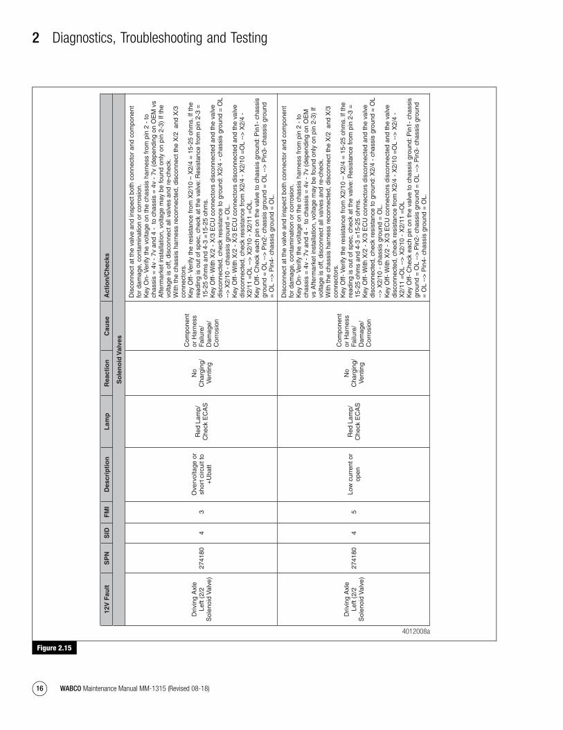
2 Diagnostics, Troubleshooting and Testing
16 WABCO Maintenance Manual MM-1315 (Revised 08-18)
Figure 2.15
Figure 2.15
12V
Fau
ltS
PN
SID
FM
ID
escr
ipti
on
Lam
pR
eact
ion
Cau
seA
ctio
n/C
hec
ks
So
len
oid
Val
ves
Driv
ing
Axl
e Le
ft (2
/2
Sol
enoi
d V
alve
)27
4180
43
Ove
rvol
tage
or
shor
t circ
uit t
o +
Uba
tt
Red
Lam
p/
Che
ck E
CA
S
No
Cha
rgin
g/
Ven
ting
Com
pone
nt
or H
arne
ss
Failu
re/
Dam
age/
C
orro
sion
Dis
conn
ect a
t the
val
ve a
nd in
spec
t bot
h co
nnec
tor
and
com
pone
nt
for
dam
age,
con
tam
inat
ion
or c
orro
sion
. K
ey O
n- V
erify
the
volta
ge o
n th
e ch
assi
s ha
rnes
s fr
om p
in 2
- to
ch
assi
s =
4v
- 7v
and
4 -
to
chas
sis
= 4
v -
7v (
depe
ndin
g on
OE
M v
s A
fterm
arke
t ins
talla
tion,
vol
tage
may
be
foun
d on
ly o
n pi
n 2-
3) If
the
volta
ge is
off,
dis
conn
ect a
ll va
lves
and
re-
chec
k.
With
the
chas
sis
harn
ess
reco
nnec
ted,
dis
conn
ect t
he X
/2 a
nd X
/3
conn
ecto
rs.
Key
Off-
Ver
ify th
e re
sist
ance
from
X2/
10 –
X2/
4 =
15-
25 o
hms.
If th
e re
adin
g is
out
of s
pec,
che
ck a
t the
val
ve: R
esis
tanc
e fr
om p
in 2
-3 =
15
-25
ohm
s an
d 4-
3 =
15-2
5 oh
ms.
K
ey O
ff- W
ith X
/2 -
X/3
EC
U c
onne
ctor
s di
scon
nect
ed a
nd th
e va
lve
disc
onne
cted
, che
ck r
esis
tanc
e to
gro
und:
X2/
4 -
chas
sis
grou
nd =
OL
-->
X2/
10 -
cha
ssis
gro
und
= O
L.
Key
Off-
With
X/2
- X
/3 E
CU
con
nect
ors
disc
onne
cted
and
the
valv
e di
scon
nect
ed, c
heck
res
ista
nce
from
X2/
4 -
X2/
10 =
OL
-->
X2/
4 -
X2/
11 =
OL
-->
X2/
10 -
X2/
11 =
OL.
K
ey O
ff- C
heck
eac
h pi
n on
the
valv
e to
cha
ssis
gro
und:
Pin
1- c
hass
is
grou
nd =
OL
-->
Pin
2- c
hass
is g
roun
d =
OL
-->
Pin
3- c
hass
is g
roun
d =
OL
-->
Pin
4- c
hass
is g
roun
d =
OL.
Driv
ing
Axl
e Le
ft (2
/2
Sol
enoi
d V
alve
)27
4180
45
Low
cur
rent
or
open
Red
Lam
p/
Che
ck E
CA
S
No
Cha
rgin
g/
Ven
ting
Com
pone
nt
or H
arne
ss
Failu
re/
Dam
age/
C
orro
sion
Dis
conn
ect a
t the
val
ve a
nd in
spec
t bot
h co
nnec
tor
and
com
pone
nt
for
dam
age,
con
tam
inat
ion
or c
orro
sion
. K
ey O
n- V
erify
the
volta
ge o
n th
e ch
assi
s ha
rnes
s fr
om p
in 2
- to
ch
assi
s =
4v
- 7v
and
4 -
to
chas
sis
= 4
v -
7v (
depe
ndin
g on
OE
M
vs A
fterm
arke
t ins
talla
tion,
vol
tage
may
be
foun
d on
ly o
n pi
n 2-
3) If
vo
ltage
is o
ff, d
isco
nnec
t all
valv
es a
nd r
e-ch
eck.
W
ith th
e ch
assi
s ha
rnes
s re
conn
ecte
d, d
isco
nnec
t the
X/2
and
X/3
co
nnec
tors
. K
ey O
ff- V
erify
the
resi
stan
ce fr
om X
2/10
– X
2/4
= 1
5-25
ohm
s. If
the
read
ing
is o
ut o
f spe
c, c
heck
at t
he v
alve
: Res
ista
nce
from
pin
2-3
=
15-2
5 oh
ms
and
4-3
=15
-25
ohm
s.
Key
Off-
With
X/2
- X
/3 E
CU
con
nect
ors
disc
onne
cted
and
the
valv
e di
scon
nect
ed, c
heck
res
ista
nce
to g
roun
d: X
2/4
- ch
assi
s gr
ound
= O
L --
> X
2/10
- c
hass
is g
roun
d =
OL.
K
ey O
ff- W
ith X
/2 -
X/3
EC
U c
onne
ctor
s di
scon
nect
ed a
nd th
e va
lve
disc
onne
cted
, che
ck r
esis
tanc
e fr
om X
2/4
- X
2/10
=O
L --
> X
2/4
- X
2/11
=O
L --
> X
2/10
- X
2/11
=O
L K
ey O
ff- C
heck
eac
h pi
n on
the
valv
e to
cha
ssis
gro
und:
Pin
1- c
hass
is
grou
nd =
OL
-->
Pin
2- c
hass
is g
roun
d =
OL
-->
Pin
3- c
hass
is g
roun
d =
OL
-->
Pin
4- c
hass
is g
roun
d =
OL.
4012008a
mm1315.bk.fm Page 16 Tuesday, July 9, 2019 7:23 PM
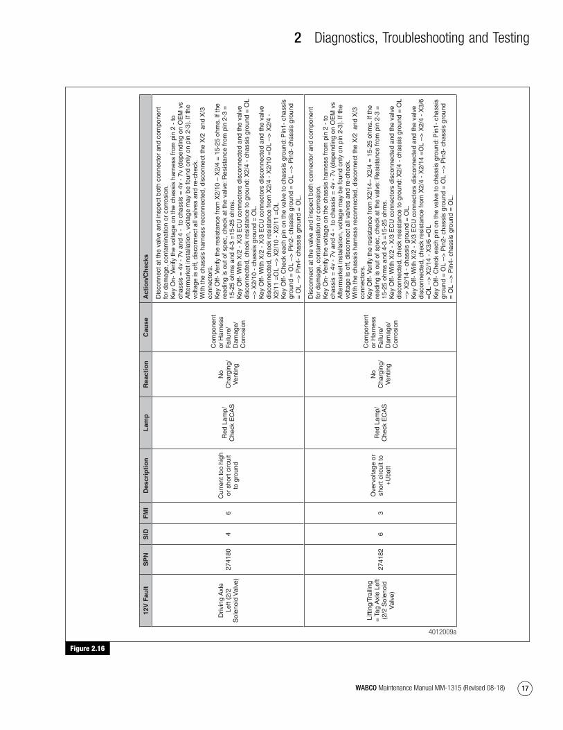
2 Diagnostics, Troubleshooting and Testing
17WABCO Maintenance Manual MM-1315 (Revised 08-18)
Figure 2.16
Figure 2.16
12V
Fau
ltS
PN
SID
FM
ID
escr
ipti
on
Lam
pR
eact
ion
Cau
seA
ctio
n/C
hec
ks
Driv
ing
Axl
e Le
ft (2
/2
Sol
enoi
d V
alve
)27
4180
46
Cur
rent
too
high
or
sho
rt c
ircui
t to
gro
und
Red
Lam
p/
Che
ck E
CA
S
No
Cha
rgin
g/
Ven
ting
Com
pone
nt
or H
arne
ss
Failu
re/
Dam
age/
C
orro
sion
Dis
conn
ect a
t the
val
ve a
nd in
spec
t bot
h co
nnec
tor
and
com
pone
nt
for
dam
age,
con
tam
inat
ion
or c
orro
sion
. K
ey O
n- V
erify
the
volta
ge o
n th
e ch
assi
s ha
rnes
s fr
om p
in 2
- to
ch
assi
s =
4v
- 7v
and
4 -
to
chas
sis
= 4
v -
7v (
depe
ndin
g on
OE
M v
s A
fterm
arke
t ins
talla
tion,
vol
tage
may
be
foun
d on
ly o
n pi
n 2-
3). I
f the
vo
ltage
is o
ff, d
isco
nnec
t all
valv
es a
nd r
e-ch
eck.
W
ith th
e ch
assi
s ha
rnes
s re
conn
ecte
d, d
isco
nnec
t the
X/2
and
X/3
co
nnec
tors
. K
ey O
ff- V
erify
the
resi
stan
ce fr
om X
2/10
– X
2/4
= 1
5-25
ohm
s. If
the
read
ing
is o
ut o
f spe
c, c
heck
at t
he v
alve
: Res
ista
nce
from
pin
2-3
=
15-2
5 oh
ms
and
4-3
=15
-25
ohm
s.
Key
Off-
With
X/2
- X
/3 E
CU
con
nect
ors
disc
onne
cted
and
the
valv
e di
scon
nect
ed, c
heck
res
ista
nce
to g
roun
d: X
2/4
- ch
assi
s gr
ound
= O
L --
> X
2/10
- c
hass
is g
roun
d =
OL.
K
ey O
ff- W
ith X
/2 -
X/3
EC
U c
onne
ctor
s di
scon
nect
ed a
nd th
e va
lve
disc
onne
cted
, che
ck r
esis
tanc
e fr
om X
2/4
- X
2/10
=O
L --
> X
2/4
- X
2/11
=O
L --
> X
2/10
- X
2/11
=O
L K
ey O
ff- C
heck
eac
h pi
n on
the
valv
e to
cha
ssis
gro
und:
Pin
1- c
hass
is
grou
nd =
OL
-->
Pin
2- c
hass
is g
roun
d =
OL
-->
Pin
3- c
hass
is g
roun
d =
OL
-->
Pin
4- c
hass
is g
roun
d =
OL.
Lifti
ng/T
raili
ng
= T
ag A
xle
Left
(2/2
Sol
enoi
d V
alve
)
2741
826
3O
verv
olta
ge o
r sh
ort c
ircui
t to
+U
batt
Red
Lam
p/
Che
ck E
CA
S
No
Cha
rgin
g/
Ven
ting
Com
pone
nt
or H
arne
ss
Failu
re/
Dam
age/
C
orro
sion
Dis
conn
ect a
t the
val
ve a
nd in
spec
t bot
h co
nnec
tor
and
com
pone
nt
for
dam
age,
con
tam
inat
ion
or c
orro
sion
. K
ey O
n- V
erify
the
volta
ge o
n th
e ch
assi
s ha
rnes
s fr
om p
in 2
- to
ch
assi
s =
4v
- 7v
and
4 -
to
chas
sis
= 4
v -
7v (
depe
ndin
g on
OE
M v
s A
fterm
arke
t ins
talla
tion,
vol
tage
may
be
foun
d on
ly o
n pi
n 2-
3). I
f the
vo
ltage
is o
ff, d
isco
nnec
t all
valv
es a
nd r
e-ch
eck.
W
ith th
e ch
assi
s ha
rnes
s re
conn
ecte
d, d
isco
nnec
t the
X/2
and
X/3
co
nnec
tors
. K
ey O
ff- V
erify
the
resi
stan
ce fr
om X
2/14
– X
2/4
= 1
5-25
ohm
s. If
the
read
ing
is o
ut o
f spe
c, c
heck
at t
he v
alve
: Res
ista
nce
from
pin
2-3
=
15-2
5 oh
ms
and
4-3
=15
-25
ohm
s.
Key
Off-
With
X/2
- X
/3 E
CU
con
nect
ors
disc
onne
cted
and
the
valv
e di
scon
nect
ed, c
heck
res
ista
nce
to g
roun
d: X
2/4
- ch
assi
s gr
ound
= O
L --
> X
2/14
- c
hass
is g
roun
d =
OL.
K
ey O
ff- W
ith X
/2 -
X/3
EC
U c
onne
ctor
s di
scon
nect
ed a
nd th
e va
lve
disc
onne
cted
, che
ck r
esis
tanc
e fr
om X
2/4
- X
2/14
=O
L --
> X
2/4
- X
3/6
=O
L --
> X
2/14
- X
3/6
=O
L K
ey O
ff- C
heck
eac
h pi
n on
the
valv
e to
cha
ssis
gro
und:
Pin
1- c
hass
is
grou
nd =
OL
-->
Pin
2- c
hass
is g
roun
d =
OL
-->
Pin
3- c
hass
is g
roun
d =
OL
-->
Pin
4- c
hass
is g
roun
d =
OL.
4012009a
mm1315.bk.fm Page 17 Tuesday, July 9, 2019 7:23 PM

2 Diagnostics, Troubleshooting and Testing
18 WABCO Maintenance Manual MM-1315 (Revised 08-18)
Figure 2.17
Figure 2.17
12V
Fau
ltS
PN
SID
FM
ID
escr
ipti
on
Lam
pR
eact
ion
Cau
seA
ctio
n/C
hec
ks
Lifti
ng/T
raili
ng
= T
ag A
xle
Left
(2/2
Sol
enoi
d V
alve
)
2741
826
5Lo
w c
urre
nt o
r op
enR
ed L
amp/
C
heck
EC
AS
No
Cha
rgin
g/
Ven
ting
Com
pone
nt
or H
arne
ss
Failu
re/
Dam
age/
C
orro
sion
Dis
conn
ect a
t the
val
ve a
nd in
spec
t bot
h co
nnec
tor
and
com
pone
nt
for
dam
age,
con
tam
inat
ion
or c
orro
sion
. K
ey O
n- V
erify
the
volta
ge o
n th
e ch
assi
s ha
rnes
s fr
om p
in 2
- to
ch
assi
s =
4v
- 7v
and
4 -
to
chas
sis
= 4
v -
7v (
depe
ndin
g on
OE
M v
s A
fterm
arke
t ins
talla
tion,
vol
tage
may
be
foun
d on
ly o
n pi
n 2-
3). I
f the
vo
ltage
is o
ff, d
isco
nnec
t all
valv
es a
nd r
e-ch
eck.
W
ith th
e ch
assi
s ha
rnes
s re
conn
ecte
d, d
isco
nnec
t the
X/2
and
X/3
co
nnec
tors
. K
ey O
ff- V
erify
the
resi
stan
ce fr
om X
2/14
– X
2/4
= 1
5-25
ohm
s. If
re
adin
g is
out
of s
pec,
che
ck a
t the
val
ve: R
esis
tanc
e fr
om p
in 2
-3 =
15
-25
ohm
s an
d 4-
3 =
15-2
5 oh
ms.
K
ey O
ff- W
ith X
/2 -
X/3
EC
U c
onne
ctor
s di
scon
nect
ed a
nd th
e va
lve
disc
onne
cted
, che
ck r
esis
tanc
e to
gro
und:
X2/
4 -
chas
sis
grou
nd =
OL
-->
X2/
14 -
cha
ssis
gro
und
= O
L.
Key
Off-
With
X/2
- X
/3 E
CU
con
nect
ors
disc
onne
cted
and
the
valv
e di
scon
nect
ed, c
heck
res
ista
nce
from
X2/
4 -
X2/
14 =
OL
-->
X2/
4 -
X3/
6 =
OL
-->
X2/
14 -
X3/
6 =
OL.
K
ey O
ff- C
heck
eac
h pi
n on
the
valv
e to
cha
ssis
gro
und:
Pin
1- c
hass
is
grou
nd =
OL
-->
Pin
2- c
hass
is g
roun
d =
OL
-->
Pin
3- c
hass
is g
roun
d =
OL
-->
Pin
4- c
hass
is g
roun
d =
OL.
Lifti
ng/T
raili
ng
= T
ag A
xle
Left
(2/2
Sol
enoi
d V
alve
)
2741
826
6C
urre
nt to
o hi
gh
or s
hort
circ
uit
to g
roun
d
Red
Lam
p/
Che
ck E
CA
S
No
Cha
rgin
g/
Ven
ting
Com
pone
nt
or H
arne
ss
Failu
re/
Dam
age/
C
orro
sion
Dis
conn
ect a
t the
val
ve a
nd in
spec
t bot
h co
nnec
tor
and
com
pone
nt
for
dam
age,
con
tam
inat
ion
or c
orro
sion
. K
ey O
n- V
erify
the
volta
ge o
n th
e ch
assi
s ha
rnes
s fr
om p
in 2
- to
ch
assi
s =
4v
- 7v
and
4 -
to
chas
sis
= 4
v -
7v (
depe
ndin
g on
OE
M v
s A
fterm
arke
t ins
talla
tion,
vol
tage
may
be
foun
d on
ly o
n pi
n 2-
3). I
f the
vo
ltage
is o
ff, d
isco
nnec
t all
valv
es a
nd r
e-ch
eck.
W
ith th
e ch
assi
s ha
rnes
s re
conn
ecte
d, d
isco
nnec
t the
X/2
and
X/3
co
nnec
tors
. K
ey O
ff- V
erify
the
resi
stan
ce fr
om X
2/14
– X
2/4
= 1
5-25
ohm
s. If
re
adin
g is
out
of s
pec,
che
ck a
t the
val
ve: R
esis
tanc
e fr
om p
in 2
-3 =
15
-25
ohm
s an
d 4-
3 =
15-2
5 oh
ms.
K
ey O
ff- W
ith X
/2 -
X/3
EC
U c
onne
ctor
s di
scon
nect
ed a
nd th
e va
lve
disc
onne
cted
, che
ck r
esis
tanc
e to
gro
und:
X2/
4 -
chas
sis
grou
nd =
OL
-->
X2/
14 -
cha
ssis
gro
und
= O
L.
Key
Off-
With
X/2
- X
/3 E
CU
con
nect
ors
disc
onne
cted
and
the
valv
e di
scon
nect
ed, c
heck
res
ista
nce
from
X2/
4 -
X2/
14 =
OL
-->
X2/
4 -
X3/
6 =
OL
-->
X2/
14 -
X3/
6 =
OL.
K
ey O
ff- C
heck
eac
h pi
n on
the
valv
e to
cha
ssis
gro
und:
Pin
1- c
hass
is
grou
nd =
OL
-->
Pin
2- c
hass
is g
roun
d =
OL
-->
Pin
3- c
hass
is g
roun
d =
OL
-->
Pin
4- c
hass
is g
roun
d =
OL.
4012010a
mm1315.bk.fm Page 18 Tuesday, July 9, 2019 7:23 PM

2 Diagnostics, Troubleshooting and Testing
19WABCO Maintenance Manual MM-1315 (Revised 08-18)
Figure 2.18
Figure 2.18
12V
Fau
ltS
PN
SID
FM
ID
escr
ipti
on
Lam
pR
eact
ion
Cau
seA
ctio
n/C
hec
ks
Driv
ing
Axl
e Le
ft (3
/2
Sol
enoi
d V
alve
)27
4183
73
Ove
rvol
tage
or
shor
t circ
uit t
o +
Uba
tt
Red
Lam
p/
Che
ck E
CA
S
No
Cha
rgin
g/
Ven
ting
Com
pone
nt
or H
arne
ss
Failu
re/
Dam
age/
C
orro
sion
Dis
conn
ect a
t the
val
ve a
nd in
spec
t bot
h co
nnec
tor
and
com
pone
nt
for
dam
age,
con
tam
inat
ion
or c
orro
sion
. K
ey O
n- V
erify
the
volta
ge o
n th
e ch
assi
s ha
rnes
s fr
om p
in 2
- to
ch
assi
s =
4v
- 7v
and
4 -
to
chas
sis
= 4
v -
7v (
depe
ndin
g on
OE
M
vs A
fterm
arke
t ins
talla
tion,
vol
tage
may
be
foun
d on
ly o
n pi
n 2-
3). I
f vo
ltage
is o
ff, d
isco
nnec
t all
valv
es a
nd r
e-ch
eck.
W
ith th
e ch
assi
s ha
rnes
s re
conn
ecte
d, d
isco
nnec
t the
X/2
and
X/3
co
nnec
tors
.
Key
Off-
Ver
ify th
e re
sist
ance
from
X2/
11–
X2/
4 =
15-
25 o
hms.
If
read
ing
is o
ut o
f spe
c, c
heck
at t
he v
alve
: Res
ista
nce
from
pin
2-1
=
15-2
5 oh
ms
and
4-1
=15
-25
ohm
s.
Key
Off-
With
X/2
- X
/3 E
CU
con
nect
ors
disc
onne
cted
and
the
valv
e di
scon
nect
ed, c
heck
res
ista
nce
to g
roun
d: X
2/4
- ch
assi
s gr
ound
= O
L --
> X
2/11
- c
hass
is g
roun
d =
OL.
K
ey O
ff- W
ith X
/2 -
X/3
EC
U c
onne
ctor
s di
scon
nect
ed a
nd th
e va
lve
disc
onne
cted
, che
ck r
esis
tanc
e to
X2/
4 -
X2/
11 =
OL
-->
X2/
4 -
X2/
10
=O
L --
> X
2/11
- X
2/10
=O
L.
Key
Off-
Che
ck e
ach
pin
on th
e va
lve
to c
hass
is g
roun
d: P
in1-
cha
ssis
gr
ound
= O
L --
> P
in2-
cha
ssis
gro
und
= O
L --
> P
in3-
cha
ssis
gro
und
= O
L --
> P
in4-
cha
ssis
gro
und
= O
L.
Driv
ing
Axl
e Le
ft (3
/2
Sol
enoi
d V
alve
)27
4183
75
Low
cur
rent
or
open
Red
Lam
p/
Che
ck E
CA
S
No
Cha
rgin
g/
Ven
ting
Com
pone
nt
or H
arne
ss
Failu
re/
Dam
age/
C
orro
sion
Dis
conn
ect a
t the
val
ve a
nd in
spec
t bot
h co
nnec
tor
and
com
pone
nt
for
dam
age,
con
tam
inat
ion
or c
orro
sion
. K
ey O
n- V
erify
the
volta
ge o
n th
e ch
assi
s ha
rnes
s fr
om p
in 2
- to
ch
assi
s =
4v
- 7v
and
4 -
to
chas
sis
= 4
v -
7v (
depe
ndin
g on
OE
M v
s A
fterm
arke
t ins
talla
tion,
vol
tage
may
be
foun
d on
ly o
n pi
n 2-
3). I
f the
vo
ltage
is o
ff, d
isco
nnec
t all
valv
es a
nd r
e-ch
eck.
W
ith th
e ch
assi
s ha
rnes
s re
conn
ecte
d, d
isco
nnec
t the
X/2
and
X/3
co
nnec
tors
.
Key
Off-
Ver
ify th
e re
sist
ance
from
X2/
11–
X2/
4 =
15-
25 o
hms.
If
read
ing
is o
ut o
f spe
c, c
heck
at t
he v
alve
: Res
ista
nce
from
pin
2-1
=
15-2
5 oh
ms
and
4-1
=15
-25
ohm
s.
Key
Off-
With
X/2
- X
/3 E
CU
con
nect
ors
disc
onne
cted
and
the
valv
e di
scon
nect
ed, c
heck
res
ista
nce
to g
roun
d: X
2/4
- ch
assi
s gr
ound
= O
L --
> X
2/11
- c
hass
is g
roun
d =
OL.
K
ey O
ff- W
ith X
/2 -
X/3
EC
U c
onne
ctor
s di
scon
nect
ed a
nd th
e va
lve
disc
onne
cted
, che
ck r
esis
tanc
e to
X2/
4 -
X2/
11 =
OL
-->
X2/
4 -
X2/
10
=O
L --
> X
2/11
- X
2/10
=O
L.
Key
Off-
Che
ck e
ach
pin
on th
e va
lve
to c
hass
is g
roun
d: P
in1-
cha
ssis
gr
ound
= O
L --
> P
in2-
cha
ssis
gro
und
= O
L --
> P
in3-
cha
ssis
gro
und
= O
L --
> P
in4-
cha
ssis
gro
und
= O
L.
4012011a
mm1315.bk.fm Page 19 Tuesday, July 9, 2019 7:23 PM
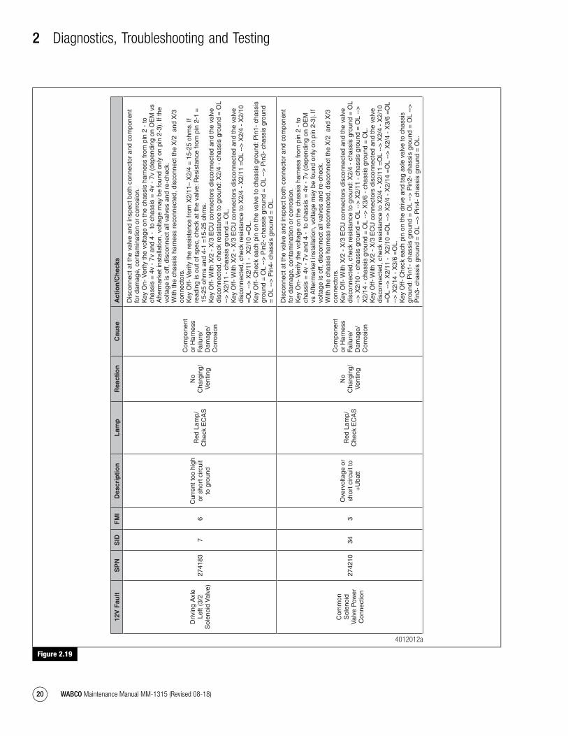
2 Diagnostics, Troubleshooting and Testing
20 WABCO Maintenance Manual MM-1315 (Revised 08-18)
Figure 2.19
Figure 2.19
12V
Fau
ltS
PN
SID
FM
ID
escr
ipti
on
Lam
pR
eact
ion
Cau
seA
ctio
n/C
hec
ks
Driv
ing
Axl
e Le
ft (3
/2
Sol
enoi
d V
alve
)27
4183
76
Cur
rent
too
high
or
sho
rt c
ircui
t to
gro
und
Red
Lam
p/
Che
ck E
CA
S
No
Cha
rgin
g/
Ven
ting
Com
pone
nt
or H
arne
ss
Failu
re/
Dam
age/
C
orro
sion
Dis
conn
ect a
t the
val
ve a
nd in
spec
t bot
h co
nnec
tor
and
com
pone
nt
for
dam
age,
con
tam
inat
ion
or c
orro
sion
. K
ey O
n- V
erify
the
volta
ge o
n th
e ch
assi
s ha
rnes
s fr
om p
in 2
- to
ch
assi
s =
4v
- 7v
and
4 -
to
chas
sis
= 4
v -
7v (
depe
ndin
g on
OE
M v
s A
fterm
arke
t ins
talla
tion,
vol
tage
may
be
foun
d on
ly o
n pi
n 2-
3). I
f the
vo
ltage
is o
ff, d
isco
nnec
t all
valv
es a
nd r
e-ch
eck.
W
ith th
e ch
assi
s ha
rnes
s re
conn
ecte
d, d
isco
nnec
t the
X/2
and
X/3
co
nnec
tors
.
Key
Off-
Ver
ify th
e re
sist
ance
from
X2/
11–
X2/
4 =
15-
25 o
hms.
If
read
ing
is o
ut o
f spe
c, c
heck
at t
he v
alve
: Res
ista
nce
from
pin
2-1
=
15-2
5 oh
ms
and
4-1
=15
-25
ohm
s.
Key
Off-
With
X/2
- X
/3 E
CU
con
nect
ors
disc
onne
cted
and
the
valv
e di
scon
nect
ed, c
heck
res
ista
nce
to g
roun
d: X
2/4
- ch
assi
s gr
ound
= O
L --
> X
2/11
- c
hass
is g
roun
d =
OL.
K
ey O
ff- W
ith X
/2 -
X/3
EC
U c
onne
ctor
s di
scon
nect
ed a
nd th
e va
lve
disc
onne
cted
, che
ck r
esis
tanc
e to
X2/
4 -
X2/
11 =
OL
-->
X2/
4 -
X2/
10
=O
L --
> X
2/11
- X
2/10
=O
L.
Key
Off-
Che
ck e
ach
pin
on th
e va
lve
to c
hass
is g
roun
d: P
in1-
cha
ssis
gr
ound
= O
L --
> P
in2-
cha
ssis
gro
und
= O
L --
> P
in3-
cha
ssis
gro
und
= O
L --
> P
in4-
cha
ssis
gro
und
= O
L.
Com
mon
S
olen
oid
Val
ve P
ower
C
onne
ctio
n
2742
1034
3O
verv
olta
ge o
r sh
ort c
ircui
t to
+U
batt
Red
Lam
p/
Che
ck E
CA
S
No
Cha
rgin
g/
Ven
ting
Com
pone
nt
or H
arne
ss
Failu
re/
Dam
age/
C
orro
sion
Dis
conn
ect a
t the
val
ve a
nd in
spec
t bot
h co
nnec
tor
and
com
pone
nt
for
dam
age,
con
tam
inat
ion
or c
orro
sion
. K
ey O
n- V
erify
the
volta
ge o
n th
e ch
assi
s ha
rnes
s fr
om p
in 2
- to
ch
assi
s =
4v
- 7v
and
4 -
to
chas
sis
= 4
v -
7v (
depe
ndin
g on
OE
M
vs A
fterm
arke
t ins
talla
tion,
vol
tage
may
be
foun
d on
ly o
n pi
n 2-
3). I
f vo
ltage
is o
ff, d
isco
nnec
t all
valv
es a
nd r
e-ch
eck.
W
ith th
e ch
assi
s ha
rnes
s re
conn
ecte
d, d
isco
nnec
t the
X/2
and
X/3
co
nnec
tors
.
Key
Off-
With
X/2
- X
/3 E
CU
con
nect
ors
disc
onne
cted
and
the
valv
e di
scon
nect
ed, c
heck
res
ista
nce
to g
roun
d: X
2/4
- ch
assi
s gr
ound
= O
L --
> X
2/10
- c
hass
is g
roun
d =
OL
-->
X2/
11 -
cha
ssis
gro
und
= O
L --
>
X2/
14 -
cha
ssis
gro
und
= O
L --
> X
3/6
- ch
assi
s gr
ound
= O
L.
Key
Off-
With
X/2
- X
/3 E
CU
con
nect
ors
disc
onne
cted
and
the
valv
e di
scon
nect
ed, c
heck
res
ista
nce
to X
2/4
- X
2/11
=O
L --
> X
2/4
- X
2/10
=
OL
-->
X2/
11 -
X2/
10 =
OL
-->
X2/
4 -
X2/
14 =
OL
-->
X2/
4 -
X3/
6 =
OL
-->
X2/
14 -
X3/
6 =
OL.
K
ey O
ff- C
heck
eac
h pi
n on
the
driv
e an
d ta
g ax
le v
alve
to c
hass
is
grou
nd: P
in1-
cha
ssis
gro
und
= O
L --
> P
in2-
cha
ssis
gro
und
= O
L --
>
Pin
3- c
hass
is g
roun
d =
OL
-->
Pin
4- c
hass
is g
roun
d =
OL.
4012012a
mm1315.bk.fm Page 20 Tuesday, July 9, 2019 7:23 PM
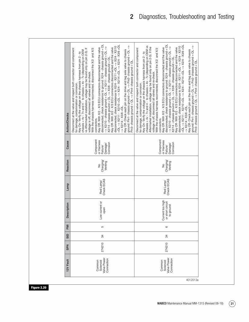
2 Diagnostics, Troubleshooting and Testing
21WABCO Maintenance Manual MM-1315 (Revised 08-18)
Figure 2.20
Figure 2.20
12V
Fau
ltS
PN
SID
FM
ID
escr
ipti
on
Lam
pR
eact
ion
Cau
seA
ctio
n/C
hec
ks
Com
mon
S
olen
oid
Val
ve P
ower
C
onne
ctio
n
2742
1034
5Lo
w c
urre
nt o
r op
enR
ed L
amp/
C
heck
EC
AS
No
Cha
rgin
g/
Ven
ting
Com
pone
nt
or H
arne
ss
Failu
re/
Dam
age/
C
orro
sion
Dis
conn
ect a
t the
val
ve a
nd in
spec
t bot
h co
nnec
tor
and
com
pone
nt
for
dam
age,
con
tam
inat
ion
or c
orro
sion
. K
ey O
n- V
erify
the
volta
ge o
n th
e ch
assi
s ha
rnes
s fr
om p
in 2
- to
ch
assi
s =
4v
- 7v
and
4 -
to
chas
sis
= 4
v -
7v (
depe
ndin
g on
OE
M
vs A
fterm
arke
t ins
talla
tion,
vol
tage
may
be
foun
d on
ly o
n pi
n 2-
3). I
f vo
ltage
is o
ff, d
isco
nnec
t all
valv
es a
nd r
e-ch
eck.
W
ith th
e ch
assi
s ha
rnes
s re
conn
ecte
d, d
isco
nnec
t the
X/2
and
X/3
co
nnec
tors
.
Key
Off-
With
X/2
- X
/3 E
CU
con
nect
ors
disc
onne
cted
and
the
valv
e di
scon
nect
ed, c
heck
res
ista
nce
to g
roun
d: X
2/4
- ch
assi
s gr
ound
= O
L --
> X
2/10
- c
hass
is g
roun
d =
OL
-->
X2/
11 -
cha
ssis
gro
und
= O
L --
>
X2/
14 -
cha
ssis
gro
und
= O
L --
> X
3/6
- ch
assi
s gr
ound
= O
L.
Key
Off-
With
X/2
- X
/3 E
CU
con
nect
ors
disc
onne
cted
and
the
valv
e di
scon
nect
ed, c
heck
res
ista
nce
to X
2/4
- X
2/11
=O
L --
> X
2/4
- X
2/10
=
OL
-->
X2/
11 -
X2/
10 =
OL
-->
X2/
4 -
X2/
14 =
OL
-->
X2/
4 -
X3/
6 =
OL
-->
X2/
14 -
X3/
6 =
OL.
K
ey O
ff- C
heck
eac
h pi
n on
the
driv
e an
d ta
g ax
le v
alve
to c
hass
is
grou
nd: P
in1-
cha
ssis
gro
und
= O
L --
> P
in2-
cha
ssis
gro
und
= O
L --
>
Pin
3- c
hass
is g
roun
d =
OL
-->
Pin
4- c
hass
is g
roun
d =
OL.
Com
mon
S
olen
oid
Val
ve P
ower
C
onne
ctio
n
2742
1034
6C
urre
nt to
o hi
gh
or s
hort
circ
uit
to g
roun
d
Red
Lam
p/
Che
ck E
CA
S
No
Cha
rgin
g/
Ven
ting
Com
pone
nt
or H
arne
ss
Failu
re/
Dam
age/
C
orro
sion
Dis
conn
ect a
t the
val
ve a
nd in
spec
t bot
h co
nnec
tor
and
com
pone
nt
for
dam
age,
con
tam
inat
ion
or c
orro
sion
. K
ey O
n- V
erify
the
volta
ge o
n th
e ch
assi
s ha
rnes
s fr
om p
in 2
- to
ch
assi
s =
4v
- 7v
and
4 -
to
chas
sis
= 4
v -
7v (
depe
ndin
g on
OE
M v
s A
fterm
arke
t ins
talla
tion,
vol
tage
may
be
foun
d on
ly o
n pi
n 2-
3). I
f the
vo
ltage
is o
ff, d
isco
nnec
t all
valv
es a
nd r
e-ch
eck.
W
ith th
e ch
assi
s ha
rnes
s re
conn
ecte
d, d
isco
nnec
t the
X/2
and
X/3
co
nnec
tors
.
Key
Off-
With
X/2
- X
/3 E
CU
con
nect
ors
disc
onne
cted
and
the
valv
e di
scon
nect
ed, c
heck
res
ista
nce
to g
roun
d: X
2/4
- ch
assi
s gr
ound
= O
L --
> X
2/10
- c
hass
is g
roun
d =
OL
-->
X2/
11 -
cha
ssis
gro
und
= O
L --
>
X2/
14 -
cha
ssis
gro
und
= O
L --
> X
3/6
- ch
assi
s gr
ound
= O
L.
Key
Off-
With
X/2
- X
/3 E
CU
con
nect
ors
disc
onne
cted
and
the
valv
e di
scon
nect
ed, c
heck
res
ista
nce
to X
2/4
- X
2/11
=O
L --
> X
2/4
- X
2/10
=
OL
-->
X2/
11 -
X2/
10 =
OL
-->
X2/
4 -
X2/
14 =
OL
-->
X2/
4 -
X3/
6 =
OL
-->
X2/
14 -
X3/
6 =
OL.
K
ey O
ff- C
heck
eac
h pi
n on
the
driv
e an
d ta
g ax
le v
alve
to c
hass
is
grou
nd: P
in1-
cha
ssis
gro
und
= O
L --
> P
in2-
cha
ssis
gro
und
= O
L --
>
Pin
3- c
hass
is g
roun
d =
OL
-->
Pin
4- c
hass
is g
roun
d =
OL.
4012013a
mm1315.bk.fm Page 21 Tuesday, July 9, 2019 7:23 PM

2 Diagnostics, Troubleshooting and Testing
22 WABCO Maintenance Manual MM-1315 (Revised 08-18)
Figure 2.21
Figure 2.21
12V
Fau
ltS
PN
SID
FM
ID
escr
ipti
on
Lam
pR
eact
ion
Cau
seA
ctio
n/C
hec
ks
Lifti
ng/T
raili
ng
= T
ag A
xle
Left
(3/2
Sol
enoi
d V
alve
)
2742
1943
3O
verv
olta
ge o
r sh
ort c
ircui
t to
+U
batt
Red
Lam
p/
Che
ck E
CA
S
No
Cha
rgin
g/
Ven
ting
Com
pone
nt
or H
arne
ss
Failu
re/
Dam
age/
C
orro
sion
Dis
conn
ect a
t the
val
ve a
nd in
spec
t bot
h co
nnec
tor
and
com
pone
nt
for
dam
age,
con
tam
inat
ion
or c
orro
sion
. K
ey O
n- V
erify
the
volta
ge o
n th
e ch
assi
s ha
rnes
s fr
om p
in 2
- to
ch
assi
s =
4v
- 7v
and
4 -
to
chas
sis
= 4
v -
7v (
depe
ndin
g on
OE
M v
s A
fterm
arke
t ins
talla
tion,
vol
tage
may
be
foun
d on
ly o
n pi
n 2-
3). I
f the
vo
ltage
is o
ff, d
isco
nnec
t all
valv
es a
nd r
e-ch
eck.
W
ith th
e ch
assi
s ha
rnes
s re
conn
ecte
d, d
isco
nnec
t the
X/2
and
X/3
co
nnec
tors
.
Key
Off-
Ver
ify th
e re
sist
ance
from
X2/
4– X
3/6
= 1
5-25
ohm
s. If
re
adin
g is
out
of s
pec,
che
ck a
t the
val
ve: R
esis
tanc
e fr
om p
in 2
-1 =
15
-25
ohm
s an
d 4-
1 =
15-2
5 oh
ms.
K
ey O
ff- W
ith X
/2 -
X/3
EC
U c
onne
ctor
s di
scon
nect
ed a
nd th
e va
lve
disc
onne
cted
, che
ck r
esis
tanc
e to
gro
und:
X2/
4 -
chas
sis
grou
nd =
OL
-->
X3/
6 -
chas
sis
grou
nd =
OL.
K
ey O
ff- W
ith X
/2 -
X/3
EC
U c
onne
ctor
s di
scon
nect
ed a
nd th
e va
lve
disc
onne
cted
, che
ck r
esis
tanc
e to
X2/
4 -
X2/
14 =
OL
-->
X2/
4 -
X3/
6 =
OL
-->
X2/
14 -
X3/
6 =
OL.
K
ey O
ff- C
heck
eac
h pi
n on
the
valv
e to
cha
ssis
gro
und:
Pin
1- c
hass
is
grou
nd =
OL
-->
Pin
2- c
hass
is g
roun
d =
OL
-->
Pin
3- c
hass
is g
roun
d =
OL
-->
Pin
4- c
hass
is g
roun
d =
OL.
Lifti
ng/T
raili
ng
= T
ag A
xle
Left
(3/2
Sol
enoi
d V
alve
)
2742
1943
5Lo
w c
urre
nt o
r op
enR
ed L
amp/
C
heck
EC
AS
No
Cha
rgin
g/
Ven
ting
Com
pone
nt
or H
arne
ss
Failu
re/
Dam
age/
C
orro
sion
Dis
conn
ect a
t the
val
ve a
nd in
spec
t bot
h co
nnec
tor
and
com
pone
nt
for
dam
age,
con
tam
inat
ion
or c
orro
sion
. K
ey O
n- V
erify
the
volta
ge o
n th
e ch
assi
s ha
rnes
s fr
om p
in 2
- to
ch
assi
s =
4v
- 7v
and
4 -
to
chas
sis
= 4
v -
7v (
depe
ndin
g on
OE
M v
s A
fterm
arke
t ins
talla
tion,
vol
tage
may
be
foun
d on
ly o
n pi
n 2-
3) If
the
volta
ge is
off,
dis
conn
ect a
ll va
lves
and
re-
chec
k.
With
the
chas
sis
harn
ess
reco
nnec
ted,
dis
conn
ect t
he X
/2 a
nd X
/3
conn
ecto
rs.
K
ey O
ff- V
erify
the
resi
stan
ce fr
om X
2/4–
X3/
6 =
15-
25 o
hms.
If
read
ing
is o
ut o
f spe
c, c
heck
at t
he v
alve
: Res
ista
nce
from
pin
2-1
=
15-2
5 oh
ms
and
4-1
=15
-25
ohm
s.
Key
Off-
With
X/2
- X
/3 E
CU
con
nect
ors
disc
onne
cted
and
the
valv
e di
scon
nect
ed, c
heck
res
ista
nce
to g
roun
d: X
2/4
- ch
assi
s gr
ound
= O
L --
> X
3/6
- ch
assi
s gr
ound
= O
L.
Key
Off-
With
X/2
- X
/3 E
CU
con
nect
ors
disc
onne
cted
and
the
valv
e di
scon
nect
ed, c
heck
res
ista
nce
to X
2/4
- X
2/14
=O
L --
> X
2/4
- X
3/6
=O
L --
> X
2/14
- X
3/6
=O
L.
Key
Off-
Che
ck e
ach
pin
on th
e va
lve
to c
hass
is g
roun
d: P
in1-
cha
ssis
gr
ound
= O
L --
> P
in2-
cha
ssis
gro
und
= O
L --
> P
in3-
cha
ssis
gro
und
= O
L --
> P
in4-
cha
ssis
gro
und
= O
L.
4012014a
mm1315.bk.fm Page 22 Tuesday, July 9, 2019 7:23 PM

2 Diagnostics, Troubleshooting and Testing
23WABCO Maintenance Manual MM-1315 (Revised 08-18)
Figure 2.22
Figure 2.22
12V
Fau
ltS
PN
SID
FM
ID
escr
ipti
on
Lam
pR
eact
ion
Cau
seA
ctio
n/C
hec
ks
Lifti
ng/T
raili
ng
= T
ag A
xle
Left
(3/2
Sol
enoi
d V
alve
)
2742
1943
6C
urre
nt to
o hi
gh
or s
hort
circ
uit
to g
roun
d
Red
Lam
p/
Che
ck E
CA
S
No
Cha
rgin
g/
Ven
ting
Com
pone
nt
or H
arne
ss
Failu
re/
Dam
age/
C
orro
sion
"Dis
conn
ect a
t the
val
ve a
nd in
spec
t bot
h co
nnec
tor
and
com
pone
nt
for
dam
age,
con
tam
inat
ion
or c
orro
sion
. K
ey O
n- V
erify
the
volta
ge o
n th
e ch
assi
s ha
rnes
s fr
om p
in 2
- to
ch
assi
s =
4v
- 7v
and
4 -
to
chas
sis
= 4
v -
7v (
depe
ndin
g on
OE
M
vs A
fterm
arke
t ins
talla
tion,
vol
tage
may
be
foun
d on
ly o
n pi
n 2-
3). I
f vo
ltage
is o
ff, d
isco
nnec
t all
valv
es a
nd r
e-ch
eck.
W
ith th
e ch
assi
s ha
rnes
s re
conn
ecte
d, d
isco
nnec
t the
X/2
and
X/3
co
nnec
tors
.
Key
Off-
Ver
ify th
e re
sist
ance
from
X2/
4– X
3/6
= 1
5-25
ohm
s. If
re
adin
g is
out
of s
pec,
che
ck a
t the
val
ve: R
esis
tanc
e fr
om p
in 2
-1 =
15
-25
ohm
s an
d 4-
1 =
15-2
5 oh
ms.
K
ey O
ff- W
ith X
/2 -
X/3
EC
U c
onne
ctor
s di
scon
nect
ed a
nd th
e va
lve
disc
onne
cted
, che
ck r
esis
tanc
e to
gro
und:
X2/
4 -
chas
sis
grou
nd =
OL
-->
X3/
6 -
chas
sis
grou
nd =
OL.
K
ey O
ff- W
ith X
/2 -
X/3
EC
U c
onne
ctor
s di
scon
nect
ed a
nd th
e va
lve
disc
onne
cted
, che
ck r
esis
tanc
e to
X2/
4 -
X2/
14 =
OL
-->
X2/
4 -
X3/
6 =
OL
-->
X2/
14 -
X3/
6 =
OL.
K
ey O
ff- C
heck
eac
h pi
n on
the
valv
e to
cha
ssis
gro
und:
Pin
1- c
hass
is
grou
nd =
OL
-->
Pin
2- c
hass
is g
roun
d =
OL
-->
Pin
3- c
hass
is g
roun
d =
OL
-->
Pin
4- c
hass
is g
roun
d =
OL.
"
Rem
ote
Co
ntr
ol U
nit
Rem
ote
Con
trol
Uni
t27
4209
3311
Faul
t can
not b
e id
entifi
edR
ed L
amp/
C
heck
EC
AS
No
Aut
omat
ic
or M
anua
l F
unct
ion
Rem
ote
Dam
aged
or
Faul
ty
Dis
conn
ect a
nd in
spec
t bot
h co
nnec
tor
and
com
pone
nt fo
r da
mag
e,
cont
amin
atio
n or
cor
rosi
on.
Ver
ify p
ower
and
gro
und
to th
e R
CU
: Key
On-
Pin
1 -
2 on
the
harn
ess
side
of t
he c
onne
ctor
= 9
- 1
4 v.
UB
for
Rem
ote
Con
trol
Uni
t27
4223
473
Ove
rvol
tage
or
shor
t circ
uit t
o +
Uba
tt
Red
Lam
p/
Che
ck E
CA
S
No
Aut
omat
ic
or M
anua
l F
unct
ion
Com
pone
nt
or H
arne
ss
Dam
age
Dis
conn
ect a
nd in
spec
t bot
h co
nnec
tor
and
com
pone
nt fo
r da
mag
e,
cont
amin
atio
n or
cor
rosi
on.
Ver
ify p
ower
and
gro
und
to th
e R
CU
: Key
On-
Pin
1 -
2 on
the
harn
ess
side
of t
he c
onne
ctor
= 9
- 1
4 v.
UB
for
Rem
ote
Con
trol
Uni
t27
4223
476
Cur
rent
too
high
or
sho
rt c
ircui
t to
gro
und
Red
Lam
p/
Che
ck E
CA
S
No
Aut
omat
ic
or M
anua
l F
unct
ion
Com
pone
nt
or H
arne
ss
Dam
age
Dis
conn
ect
and
insp
ect b
oth
conn
ecto
r an
d co
mpo
nent
for
dam
age,
co
ntam
inat
ion
or c
orro
sion
. V
erify
pow
er a
nd g
roun
d to
the
RC
U:
Key
On-
Pin
1 -
2 on
the
chas
sis
harn
ess
conn
ecto
r =
9 -
14
v.
Key
Off-
Pin
2 to
cha
ssis
gro
und
varie
s w
hen
goin
g th
roug
h E
CU
(no
t O
L).
Key
Off-
X1
EC
U c
onne
ctor
dis
conn
ecte
d. O
n th
e ch
assi
s ha
rnes
s co
nnec
tor
Pin
1 -
cha
ssis
gro
und
= O
L --
> P
in 2
- c
hass
is g
roun
d =
O
L --
> P
in 3
- c
hass
is g
roun
d =
OL
-->
Pin
4 -
cha
ssis
gro
und
= O
L.
Dat
a Li
ne27
4224
483
Ove
rvol
tage
or
shor
t circ
uit t
o +
Uba
tt
Red
Lam
p/
Che
ck E
CA
S
No
Aut
omat
ic
or M
anua
l F
unct
ion
Com
pone
nt
or H
arne
ss
Dam
age
Dis
conn
ect
and
insp
ect b
oth
conn
ecto
r an
d co
mpo
nent
for
dam
age,
co
ntam
inat
ion
or c
orro
sion
. V
erify
pow
er a
nd g
roun
d to
the
RC
U:
Key
On-
Pin
1 -
2 on
the
chas
sis
harn
ess
conn
ecto
r =
9 -
14
v.
Key
Off-
Pin
2 to
cha
ssis
gro
und
varie
s w
hen
goin
g th
roug
h E
CU
(no
t O
L).
Key
Off-
X1
EC
U c
onne
ctor
dis
conn
ecte
d. O
n th
e ch
assi
s ha
rnes
s co
nnec
tor
Pin
1 -
cha
ssis
gro
und
= O
L --
> P
in 2
- c
hass
is g
roun
d =
O
L --
> P
in 3
- c
hass
is g
roun
d =
OL
-->
Pin
4 -
cha
ssis
gro
und
= O
L.
4012015a
mm1315.bk.fm Page 23 Tuesday, July 9, 2019 7:23 PM
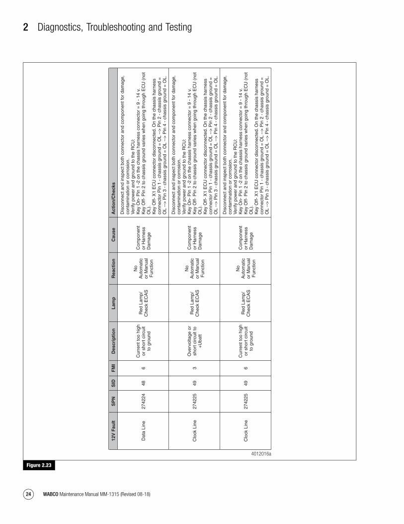
2 Diagnostics, Troubleshooting and Testing
24 WABCO Maintenance Manual MM-1315 (Revised 08-18)
Figure 2.23
Figure 2.23
12V
Fau
ltS
PN
SID
FM
ID
escr
ipti
on
Lam
pR
eact
ion
Cau
seA
ctio
n/C
hec
ks
Dat
a Li
ne27
4224
486
Cur
rent
too
high
or
sho
rt c
ircui
t to
gro
und
Red
Lam
p/
Che
ck E
CA
S
No
Aut
omat
ic
or M
anua
l F
unct
ion
Com
pone
nt
or H
arne
ss
Dam
age
Dis
conn
ect a
nd in
spec
t bot
h co
nnec
tor
and
com
pone
nt fo
r da
mag
e,
cont
amin
atio
n or
cor
rosi
on.
Ver
ify p
ower
and
gro
und
to th
e R
CU
: K
ey O
n- P
in 1
-2
on th
e ch
assi
s ha
rnes
s co
nnec
tor
= 9
- 1
4 v.
K
ey O
ff- P
in 2
to c
hass
is g
roun
d va
ries
whe
n go
ing
thro
ugh
EC
U (
not
OL)
. K
ey O
ff- X
1 E
CU
con
nect
or d
isco
nnec
ted.
On
the
chas
sis
harn
ess
conn
ecto
r P
in 1
- c
hass
is g
roun
d =
OL
-->
Pin
2 -
cha
ssis
gro
und
=
OL
-->
Pin
3 -
cha
ssis
gro
und
= O
L --
> P
in 4
- c
hass
is g
roun
d =
OL.
Clo
ck L
ine
2742
2549
3O
verv
olta
ge o
r sh
ort c
ircui
t to
+U
batt
Red
Lam
p/
Che
ck E
CA
S
No
Aut
omat
ic
or M
anua
l F
unct
ion
Com
pone
nt
or H
arne
ss
Dam
age
Dis
conn
ect a
nd in
spec
t bot
h co
nnec
tor
and
com
pone
nt fo
r da
mag
e,
cont
amin
atio
n or
cor
rosi
on.
Ver
ify p
ower
and
gro
und
to th
e R
CU
: K
ey O
n- P
in 1
-2
on th
e ch
assi
s ha
rnes
s co
nnec
tor
= 9
- 1
4 v.
K
ey O
ff- P
in 2
to c
hass
is g
roun
d va
ries
whe
n go
ing
thro
ugh
EC
U (
not
OL)
. K
ey O
ff- X
1 E
CU
con
nect
or d
isco
nnec
ted.
On
the
chas
sis
harn
ess
conn
ecto
r P
in 1
- c
hass
is g
roun
d =
OL
-->
Pin
2 -
cha
ssis
gro
und
=
OL
-->
Pin
3 -
cha
ssis
gro
und
= O
L --
> P
in 4
- c
hass
is g
roun
d =
OL.
Clo
ck L
ine
2742
2549
6C
urre
nt to
o hi
gh
or s
hort
circ
uit
to g
roun
d
Red
Lam
p/
Che
ck E
CA
S
No
Aut
omat
ic
or M
anua
l F
unct
ion
Com
pone
nt
or H
arne
ss
Dam
age
Dis
conn
ect a
nd in
spec
t bot
h co
nnec
tor
and
com
pone
nt fo
r da
mag
e,
cont
amin
atio
n or
cor
rosi
on.
Ver
ify p
ower
and
gro
und
to th
e R
CU
: K
ey O
n- P
in 1
-2
on th
e ch
assi
s ha
rnes
s co
nnec
tor
= 9
- 1
4 v.
K
ey O
ff- P
in 2
to c
hass
is g
roun
d va
ries
whe
n go
ing
thro
ugh
EC
U (
not
OL)
. K
ey O
ff- X
1 E
CU
con
nect
or d
isco
nnec
ted.
On
the
chas
sis
harn
ess
conn
ecto
r P
in 1
- c
hass
is g
roun
d =
OL
-->
Pin
2 -
cha
ssis
gro
und
=
OL
-->
Pin
3 -
cha
ssis
gro
und
= O
L --
> P
in 4
- c
hass
is g
roun
d =
OL.
4012016a
mm1315.bk.fm Page 24 Tuesday, July 9, 2019 7:23 PM
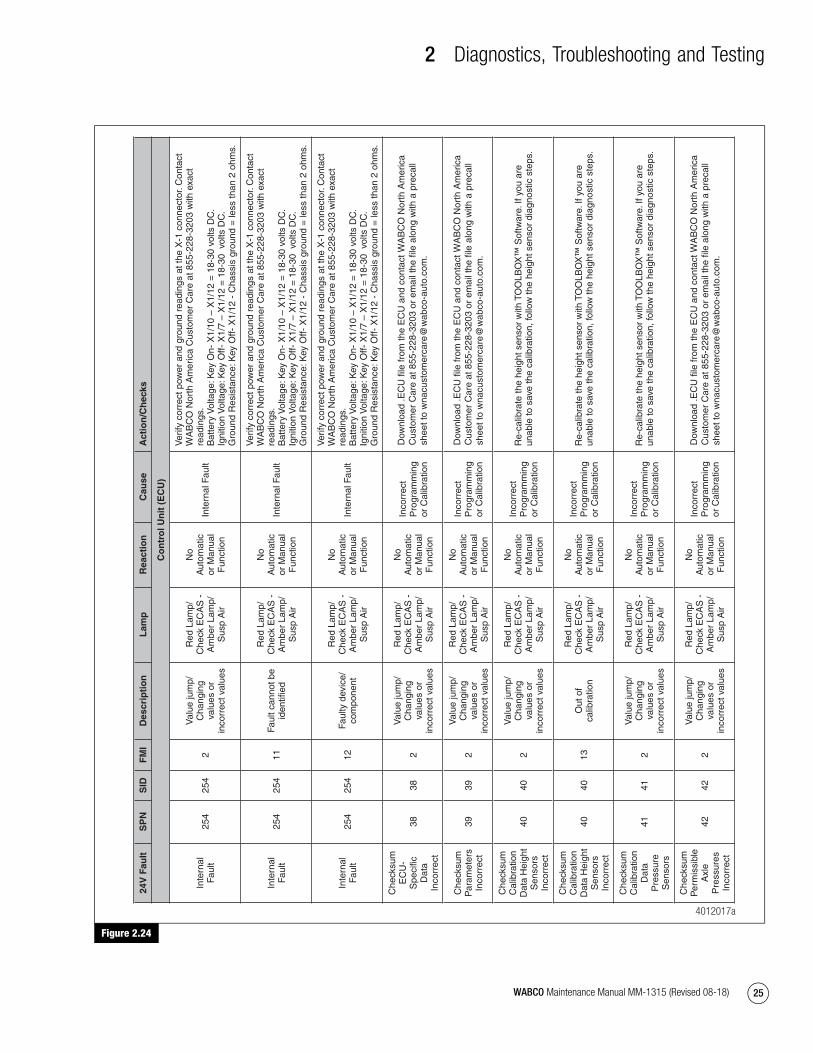
2 Diagnostics, Troubleshooting and Testing
25WABCO Maintenance Manual MM-1315 (Revised 08-18)
Figure 2.24
Figure 2.24
24V
Fau
ltS
PN
SID
FM
ID
escr
ipti
on
Lam
pR
eact
ion
Cau
seA
ctio
n/C
hec
ks
Co
ntr
ol U
nit
(E
CU
)
Inte
rnal
Fa
ult
254
254
2
Val
ue ju
mp/
Cha
ngin
g va
lues
or
inco
rrec
t val
ues
Red
Lam
p/
Che
ck E
CA
S -
A
mbe
r La
mp/
Sus
p A
ir
No
Aut
omat
ic
or M
anua
l F
unct
ion
Inte
rnal
Fau
lt
Ver
ify c
orre
ct p
ower
and
gro
und
read
ings
at t
he X
-1 c
onne
ctor
. Con
tact
W
AB
CO
Nor
th A
mer
ica
Cus
tom
er C
are
at 8
55-2
28-3
203
with
exa
ct
read
ings
. B
atte
ry V
olta
ge: K
ey O
n- X
1/10
– X
1/12
= 1
8-30
vol
ts D
C.
Igni
tion
Vol
tage
: Key
Off-
X1/
7 –
X1/
12 =
18-
30 v
olts
DC
. G
roun
d R
esis
tanc
e: K
ey O
ff- X
1/12
- C
hass
is g
roun
d =
less
than
2 o
hms.
Inte
rnal
Fa
ult
254
254
11Fa
ult c
anno
t be
iden
tified
Red
Lam
p/
Che
ck E
CA
S -
A
mbe
r La
mp/
Sus
p A
ir
No
Aut
omat
ic
or M
anua
l F
unct
ion
Inte
rnal
Fau
lt
Ver
ify c
orre
ct p
ower
and
gro
und
read
ings
at t
he X
-1 c
onne
ctor
. Con
tact
W
AB
CO
Nor
th A
mer
ica
Cus
tom
er C
are
at 8
55-2
28-3
203
with
exa
ct
read
ings
. B
atte
ry V
olta
ge: K
ey O
n- X
1/10
– X
1/12
= 1
8-30
vol
ts D
C.
Igni
tion
Vol
tage
: Key
Off-
X1/
7 –
X1/
12 =
18-
30 v
olts
DC
. G
roun
d R
esis
tanc
e: K
ey O
ff- X
1/12
- C
hass
is g
roun
d =
less
than
2 o
hms.
Inte
rnal
Fa
ult
254
254
12Fa
ulty
dev
ice/
com
pone
nt
Red
Lam
p/
Che
ck E
CA
S -
A
mbe
r La
mp/
Sus
p A
ir
No
Aut
omat
ic
or M
anua
l F
unct
ion
Inte
rnal
Fau
lt
Ver
ify c
orre
ct p
ower
and
gro
und
read
ings
at t
he X
-1 c
onne
ctor
. Con
tact
W
AB
CO
Nor
th A
mer
ica
Cus
tom
er C
are
at 8
55-2
28-3
203
with
exa
ct
read
ings
. B
atte
ry V
olta
ge: K
ey O
n- X
1/10
– X
1/12
= 1
8-30
vol
ts D
C.
Igni
tion
Vol
tage
: Key
Off-
X1/
7 –
X1/
12 =
18-
30 v
olts
DC
. G
roun
d R
esis
tanc
e: K
ey O
ff- X
1/12
- C
hass
is g
roun
d =
less
than
2 o
hms.
Che
cksu
m
EC
U-
Spe
cific
D
ata
Inco
rrec
t
3838
2
Val
ue ju
mp/
Cha
ngin
g va
lues
or
inco
rrec
t val
ues
Red
Lam
p/
Che
ck E
CA
S -
A
mbe
r La
mp/
Sus
p A
ir
No
Aut
omat
ic
or M
anua
l F
unct
ion
Inco
rrec
t P
rogr
amm
ing
or C
alib
ratio
n
Che
cksu
m
Par
amet
ers
Inco
rrec
t39
392
Val
ue ju
mp/
Cha
ngin
g va
lues
or
inco
rrec
t val
ues
Red
Lam
p/
Che
ck E
CA
S -
A
mbe
r La
mp/
Sus
p A
ir
No
Aut
omat
ic
or M
anua
l F
unct
ion
Inco
rrec
t P
rogr
amm
ing
or C
alib
ratio
n
Che
cksu
m
Cal
ibra
tion
Dat
a H
eigh
t S
enso
rs
Inco
rrec
t
4040
2
Val
ue ju
mp/
Cha
ngin
g va
lues
or
inco
rrec
t val
ues
Red
Lam
p/
Che
ck E
CA
S -
A
mbe
r La
mp/
Sus
p A
ir
No
Aut
omat
ic
or M
anua
l F
unct
ion
Inco
rrec
t P
rogr
amm
ing
or C
alib
ratio
n
Re-
calib
rate
the
heig
ht s
enso
r w
ith T
OO
LBO
X™
Sof
twar
e. If
you
are
un
able
to s
ave
the
calib
ratio
n, fo
llow
the
heig
ht s
enso
r di
agno
stic
ste
ps.
Che
cksu
m
Cal
ibra
tion
Dat
a H
eigh
t S
enso
rs
Inco
rrec
t
4040
13O
ut o
f ca
libra
tion
Red
Lam
p/
Che
ck E
CA
S -
A
mbe
r La
mp/
Sus
p A
ir
No
Aut
omat
ic
or M
anua
l F
unct
ion
Inco
rrec
t P
rogr
amm
ing
or C
alib
ratio
n
Re-
calib
rate
the
heig
ht s
enso
r w
ith T
OO
LBO
X™
Sof
twar
e. If
you
are
un
able
to s
ave
the
calib
ratio
n, fo
llow
the
heig
ht s
enso
r di
agno
stic
ste
ps.
Che
cksu
m
Cal
ibra
tion
Dat
a P
ress
ure
Sen
sors
4141
2
Val
ue ju
mp/
Cha
ngin
g va
lues
or
inco
rrec
t val
ues
Red
Lam
p/
Che
ck E
CA
S -
A
mbe
r La
mp/
Sus
p A
ir
No
Aut
omat
ic
or M
anua
l F
unct
ion
Inco
rrec
t P
rogr
amm
ing
or C
alib
ratio
n
Re-
calib
rate
the
heig
ht s
enso
r w
ith T
OO
LBO
X™
Sof
twar
e. If
you
are
un
able
to s
ave
the
calib
ratio
n, fo
llow
the
heig
ht s
enso
r di
agno
stic
ste
ps.
Che
cksu
m
Per
mis
sibl
e A
xle
Pre
ssur
es
Inco
rrec
t
4242
2
Val
ue ju
mp/
Cha
ngin
g va
lues
or
inco
rrec
t val
ues
Red
Lam
p/
Che
ck E
CA
S -
A
mbe
r La
mp/
Sus
p A
ir
No
Aut
omat
ic
or M
anua
l F
unct
ion
Inco
rrec
t P
rogr
amm
ing
or C
alib
ratio
n
Dow
nloa
d .E
CU
file
from
the
EC
U a
nd c
onta
ct W
AB
CO
Nor
th A
mer
ica
Cus
tom
er C
are
at 8
55-2
28-3
203
or e
mai
l the
file
alo
ng w
ith a
pre
call
shee
t to
wna
cust
omer
care
@w
abco
-aut
o.co
m.
Dow
nloa
d .E
CU
file
from
the
EC
U a
nd c
onta
ct W
AB
CO
Nor
th A
mer
ica
Cus
tom
er C
are
at 8
55-2
28-3
203
or e
mai
l the
file
alo
ng w
ith a
pre
call
shee
t to
wna
cust
omer
care
@w
abco
-aut
o.co
m.
Dow
nloa
d .E
CU
file
from
the
EC
U a
nd c
onta
ct W
AB
CO
Nor
th A
mer
ica
Cus
tom
er C
are
at 8
55-2
28-3
203
or e
mai
l the
file
alo
ng w
ith a
pre
call
shee
t to
wna
cust
omer
care
@w
abco
-aut
o.co
m.
4012017a
mm1315.bk.fm Page 25 Tuesday, July 9, 2019 7:23 PM
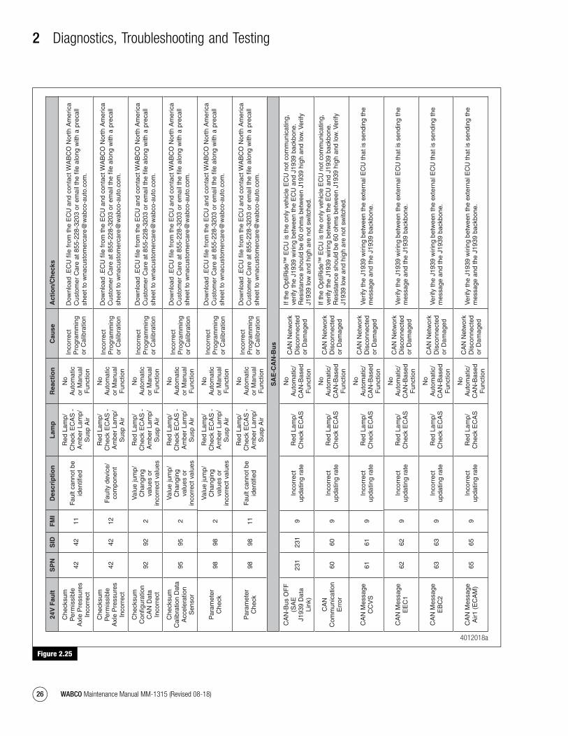
2 Diagnostics, Troubleshooting and Testing
26 WABCO Maintenance Manual MM-1315 (Revised 08-18)
Figure 2.25
Figure 2.25
24V
Fau
ltS
PN
SID
FM
ID
escr
ipti
on
Lam
pR
eact
ion
Cau
seA
ctio
n/C
hec
ks
Che
cksu
m
Per
mis
sibl
e A
xle
Pre
ssur
es
Inco
rrec
t
4242
11Fa
ult c
anno
t be
iden
tified
Red
Lam
p/
Che
ck E
CA
S -
A
mbe
r La
mp/
Sus
p A
ir
No
Aut
omat
ic
or M
anua
l F
unct
ion
Inco
rrec
t P
rogr
amm
ing
or C
alib
ratio
n
Che
cksu
m
Per
mis
sibl
e A
xle
Pre
ssur
es
Inco
rrec
t
4242
12Fa
ulty
dev
ice/
com
pone
nt
Red
Lam
p/
Che
ck E
CA
S -
A
mbe
r La
mp/
Sus
p A
ir
No
Aut
omat
ic
or M
anua
l F
unct
ion
Inco
rrec
t P
rogr
amm
ing
or C
alib
ratio
n
Che
cksu
m
Con
figur
atio
n C
AN
Dat
a In
corr
ect
9292
2
Val
ue ju
mp/
Cha
ngin
g va
lues
or
inco
rrec
t val
ues
Red
Lam
p/
Che
ck E
CA
S -
A
mbe
r La
mp/
Sus
p A
ir
No
Aut
omat
ic
or M
anua
l F
unct
ion
Inco
rrec
t P
rogr
amm
ing
or C
alib
ratio
n
Che
cksu
m
Cal
ibra
tion
Dat
a A
ccel
erat
ion
Sen
sor
9595
2
Val
ue ju
mp/
Cha
ngin
g va
lues
or
inco
rrec
t val
ues
Red
Lam
p/
Che
ck E
CA
S -
A
mbe
r La
mp/
Sus
p A
ir
No
Aut
omat
ic
or M
anua
l F
unct
ion
Inco
rrec
t P
rogr
amm
ing
or C
alib
ratio
n
Par
amet
er
Che
ck98
982
Val
ue ju
mp/
Cha
ngin
g va
lues
or
inco
rrec
t val
ues
Red
Lam
p/
Che
ck E
CA
S -
A
mbe
r La
mp/
Sus
p A
ir
No
Aut
omat
ic
or M
anua
l F
unct
ion
Inco
rrec
t P
rogr
amm
ing
or C
alib
ratio
n
Par
amet
er
Che
ck98
9811
Faul
t can
not b
e id
entifi
ed
Red
Lam
p/
Che
ck E
CA
S -
A
mbe
r La
mp/
Sus
p A
ir
No
Aut
omat
ic
or M
anua
l F
unct
ion
Inco
rrec
t P
rogr
amm
ing
or C
alib
ratio
n
SA
E-C
AN
-Bu
s
CA
N-B
us O
FF
(S
AE
J1
939
Dat
a Li
nk)
231
231
9In
corr
ect
upda
ting
rate
Red
Lam
p/
Che
ck E
CA
S
No
Aut
omat
ic/
CA
N-B
ased
F
unct
ion
CA
N N
etw
ork
Dis
conn
ecte
d or
Dam
aged
If th
e O
ptiR
ide™
EC
U is
the
only
veh
icle
EC
U n
ot c
omm
unic
atin
g,
verif
y th
e J1
939
wiri
ng b
etw
een
the
EC
U a
nd J
1939
bac
kbon
e.
Res
ista
nce
shou
ld b
e 60
ohm
s be
twee
n J1
939
high
and
low
. Ver
ify
J193
9 lo
w a
nd h
igh
are
not s
witc
hed.
CA
N
Com
mun
icat
ion
Err
or60
609
Inco
rrec
t up
datin
g ra
teR
ed L
amp/
C
heck
EC
AS
No
Aut
omat
ic/
CA
N-B
ased
F
unct
ion
CA
N N
etw
ork
Dis
conn
ecte
d or
Dam
aged
If th
e O
ptiR
ide™
EC
U is
the
only
veh
icle
EC
U n
ot c
omm
unic
atin
g,
verif
y th
e J1
939
wiri
ng b
etw
een
the
EC
U a
nd J
1939
bac
kbon
e.
Res
ista
nce
shou
ld b
e 60
ohm
s be
twee
n J1
939
high
and
low
. Ver
ify
J193
9 lo
w a
nd h
igh
are
not s
witc
hed.
CA
N M
essa
ge
CC
VS
6161
9In
corr
ect
upda
ting
rate
Red
Lam
p/
Che
ck E
CA
S
No
Aut
omat
ic/
CA
N-B
ased
F
unct
ion
CA
N N
etw
ork
Dis
conn
ecte
d or
Dam
aged
Ver
ify th
e J1
939
wiri
ng b
etw
een
the
exte
rnal
EC
U th
at is
sen
ding
the
mes
sage
and
the
J193
9 ba
ckbo
ne.
CA
N M
essa
ge
EE
C1
6262
9In
corr
ect
upda
ting
rate
Red
Lam
p/
Che
ck E
CA
S
No
Aut
omat
ic/
CA
N-B
ased
F
unct
ion
CA
N N
etw
ork
Dis
conn
ecte
d or
Dam
aged
Ver
ify th
e J1
939
wiri
ng b
etw
een
the
exte
rnal
EC
U th
at is
sen
ding
the
mes
sage
and
the
J193
9 ba
ckbo
ne.
CA
N M
essa
ge
EB
C2
6363
9In
corr
ect
upda
ting
rate
Red
Lam
p/
Che
ck E
CA
S
No
Aut
omat
ic/
CA
N-B
ased
F
unct
ion
CA
N N
etw
ork
Dis
conn
ecte
d or
Dam
aged
Ver
ify th
e J1
939
wiri
ng b
etw
een
the
exte
rnal
EC
U th
at is
sen
ding
the
mes
sage
and
the
J193
9 ba
ckbo
ne.
CA
N M
essa
ge
Air1
(E
CA
M)
6565
9In
corr
ect
upda
ting
rate
Red
Lam
p/
Che
ck E
CA
S
No
Aut
omat
ic/
CA
N-B
ased
F
unct
ion
CA
N N
etw
ork
Dis
conn
ecte
d or
Dam
aged
Ver
ify th
e J1
939
wiri
ng b
etw
een
the
exte
rnal
EC
U th
at is
sen
ding
the
mes
sage
and
the
J193
9 ba
ckbo
ne.
Dow
nloa
d .E
CU
file
from
the
EC
U a
nd c
onta
ct W
AB
CO
Nor
th A
mer
ica
Cus
tom
er C
are
at 8
55-2
28-3
203
or e
mai
l the
file
alo
ng w
ith a
pre
call
shee
t to
wna
cust
omer
care
@w
abco
-aut
o.co
m.
Dow
nloa
d .E
CU
file
from
the
EC
U a
nd c
onta
ct W
AB
CO
Nor
th A
mer
ica
Cus
tom
er C
are
at 8
55-2
28-3
203
or e
mai
l the
file
alo
ng w
ith a
pre
call
shee
t to
wna
cust
omer
care
@w
abco
-aut
o.co
m.
Dow
nloa
d .E
CU
file
from
the
EC
U a
nd c
onta
ct W
AB
CO
Nor
th A
mer
ica
Cus
tom
er C
are
at 8
55-2
28-3
203
or e
mai
l the
file
alo
ng w
ith a
pre
call
shee
t to
wna
cust
omer
care
@w
abco
-aut
o.co
m.
Dow
nloa
d .E
CU
file
from
the
EC
U a
nd c
onta
ct W
AB
CO
Nor
th A
mer
ica
Cus
tom
er C
are
at 8
55-2
28-3
203
or e
mai
l the
file
alo
ng w
ith a
pre
call
shee
t to
wna
cust
omer
care
@w
abco
-aut
o.co
m.
Dow
nloa
d .E
CU
file
from
the
EC
U a
nd c
onta
ct W
AB
CO
Nor
th A
mer
ica
Cus
tom
er C
are
at 8
55-2
28-3
203
or e
mai
l the
file
alo
ng w
ith a
pre
call
shee
t to
wna
cust
omer
care
@w
abco
-aut
o.co
m.
Dow
nloa
d .E
CU
file
from
the
EC
U a
nd c
onta
ct W
AB
CO
Nor
th A
mer
ica
Cus
tom
er C
are
at 8
55-2
28-3
203
or e
mai
l the
file
alo
ng w
ith a
pre
call
shee
t to
wna
cust
omer
care
@w
abco
-aut
o.co
m.
4012018a
mm1315.bk.fm Page 26 Tuesday, July 9, 2019 7:23 PM

2 Diagnostics, Troubleshooting and Testing
27WABCO Maintenance Manual MM-1315 (Revised 08-18)
Figure 2.26
Figure 2.2624
V F
ault
SP
NS
IDF
MI
Des
crip
tio
nL
amp
Rea
ctio
nC
ause
Act
ion
/Ch
ecks
CA
N M
essa
ge
TC
O 1
6868
9In
corr
ect
upda
ting
rate
Red
Lam
p/
Che
ck E
CA
S
No
Aut
omat
ic/
CA
N-B
ased
F
unct
ion
CA
N N
etw
ork
Dis
conn
ecte
d or
Dam
aged
Ver
ify th
e J1
939
wiri
ng b
etw
een
the
exte
rnal
EC
U th
at is
sen
ding
the
mes
sage
and
the
J193
9 ba
ckbo
ne.
CA
N M
essa
ge
Tim
e/D
ate
6969
9In
corr
ect
upda
ting
rate
Red
Lam
p/
Che
ck E
CA
S
No
Aut
omat
ic/
CA
N-B
ased
F
unct
ion
CA
N N
etw
ork
Dis
conn
ecte
d or
Dam
aged
Ver
ify th
e J1
939
wiri
ng b
etw
een
the
exte
rnal
EC
U th
at is
sen
ding
the
mes
sage
and
the
J193
9 ba
ckbo
ne.
CA
N M
essa
ge
Art
icul
atio
n In
form
atio
n73
739
Inco
rrec
t up
datin
g ra
teR
ed L
amp/
C
heck
EC
AS
No
Aut
omat
ic/
CA
N-B
ased
F
unct
ion
CA
N N
etw
ork
Dis
conn
ecte
d or
Dam
aged
Ver
ify th
e J1
939
wiri
ng b
etw
een
the
exte
rnal
EC
U th
at is
sen
ding
the
mes
sage
and
the
J193
9 ba
ckbo
ne.
CA
N M
essa
ge
AS
C2_
C74
749
Inco
rrec
t up
datin
g ra
teR
ed L
amp/
C
heck
EC
AS
No
Aut
omat
ic/
CA
N-B
ased
F
unct
ion
CA
N N
etw
ork
Dis
conn
ecte
d or
Dam
aged
Ver
ify th
e J1
939
wiri
ng b
etw
een
the
exte
rnal
EC
U th
at is
sen
ding
the
mes
sage
and
the
J193
9 ba
ckbo
ne.
CA
N M
essa
ge
AS
C2_
A75
759
Inco
rrec
t up
datin
g ra
teR
ed L
amp/
C
heck
EC
AS
No
Aut
omat
ic/
CA
N-B
ased
F
unct
ion
CA
N N
etw
ork
Dis
conn
ecte
d or
Dam
aged
Ver
ify th
e J1
939
wiri
ng b
etw
een
the
exte
rnal
EC
U th
at is
sen
ding
the
mes
sage
and
the
J193
9 ba
ckbo
ne.
CA
N M
essa
ge
AS
C2_
B76
769
Inco
rrec
t up
datin
g ra
teR
ed L
amp/
C
heck
EC
AS
No
Aut
omat
ic/
CA
N-B
ased
F
unct
ion
CA
N N
etw
ork
Dis
conn
ecte
d or
Dam
aged
Ver
ify th
e J1
939
wiri
ng b
etw
een
the
exte
rnal
EC
U th
at is
sen
ding
the
mes
sage
and
the
J193
9 ba
ckbo
ne.
CA
N M
essa
ge
AS
C6_
A77
779
Inco
rrec
t up
datin
g ra
teR
ed L
amp/
C
heck
EC
AS
No
Aut
omat
ic/
CA
N-B
ased
F
unct
ion
CA
N N
etw
ork
Dis
conn
ecte
d or
Dam
aged
Ver
ify th
e J1
939
wiri
ng b
etw
een
the
exte
rnal
EC
U th
at is
sen
ding
the
mes
sage
and
the
J193
9 ba
ckbo
ne.
CA
N M
essa
ge
AS
C6_
B78
789
Inco
rrec
t up
datin
g ra
teR
ed L
amp/
C
heck
EC
AS
No
Aut
omat
ic/
CA
N-B
ased
F
unct
ion
CA
N N
etw
ork
Dis
conn
ecte
d or
Dam
aged
Ver
ify th
e J1
939
wiri
ng b
etw
een
the
exte
rnal
EC
U th
at is
sen
ding
the
mes
sage
and
the
J193
9 ba
ckbo
ne.
CA
N M
essa
ge
Doo
r C
ontr
ol79
799
Inco
rrec
t up
datin
g ra
teR
ed L
amp/
C
heck
EC
AS
No
Aut
omat
ic/
CA
N-B
ased
F
unct
ion
CA
N N
etw
ork
Dis
conn
ecte
d or
Dam
aged
Ver
ify th
e J1
939
wiri
ng b
etw
een
the
exte
rnal
EC
U th
at is
sen
ding
the
mes
sage
and
the
J193
9 ba
ckbo
ne.
CA
N M
essa
ge
EB
C1
8080
9In
corr
ect
upda
ting
rate
Red
Lam
p/
Che
ck E
CA
S
No
Aut
omat
ic/
CA
N-B
ased
F
unct
ion
CA
N N
etw
ork
Dis
conn
ecte
d or
Dam
aged
Ver
ify th
e J1
939
wiri
ng b
etw
een
the
exte
rnal
EC
U th
at is
sen
ding
the
mes
sage
and
the
J193
9 ba
ckbo
ne.
CA
N M
essa
ge
VD
HR
101
101
9In
corr
ect
upda
ting
rate
Red
Lam
p/
Che
ck E
CA
S
No
Aut
omat
ic/
CA
N-B
ased
F
unct
ion
CA
N N
etw
ork
Dis
conn
ecte
d or
Dam
aged
Ver
ify th
e J1
939
wiri
ng b
etw
een
the
exte
rnal
EC
U th
at is
sen
ding
the
mes
sage
and
the
J193
9 ba
ckbo
ne.
CA
N M
essa
ge
HR
W10
310
39
Inco
rrec
t up
datin
g ra
teR
ed L
amp/
C
heck
EC
AS
No
Aut
omat
ic/
CA
N-B
ased
F
unct
ion
CA
N N
etw
ork
Dis
conn
ecte
d or
Dam
aged
Ver
ify th
e J1
939
wiri
ng b
etw
een
the
exte
rnal
EC
U th
at is
sen
ding
the
mes
sage
and
the
J193
9 ba
ckbo
ne.
4012019a
mm1315.bk.fm Page 27 Tuesday, July 9, 2019 7:23 PM

2 Diagnostics, Troubleshooting and Testing
28 WABCO Maintenance Manual MM-1315 (Revised 08-18)
Figure 2.27
Figure 2.27
24V
Fau
ltS
PN
SID
FM
ID
escr
ipti
on
Lam
pR
eact
ion
Cau
seA
ctio
n/C
hec
ks
Hei
gh
t S
enso
rs
Fron
t Axl
e R
ight
1616
2
Val
ue ju
mp/
Cha
ngin
g va
lues
or
inco
rrec
t val
ues
Red
Lam
p/
Che
ck E
CA
S -
A
mbe
r La
mp/
Sus
p A
ir
No
Aut
omat
ic
or M
anua
l F
unct
ion/
In
corr
ect
Rid
e H
eigh
t
Com
pone
nt
or H
arne
ss
Failu
re/
Dam
age/
C
orro
sion
Dis
conn
ect a
t the
hei
ght s
enso
r an
d in
spec
t bot
h co
nnec
tor
and
com
pone
nt fo
r da
mag
e, c
onta
min
atio
n or
cor
rosi
on.
Dis
conn
ect b
oth
the
X-2
and
X-3
con
nect
or a
t the
EC
U: K
ey O
ff-
Res
ista
nce
from
X2/
7 -
X2/
5 =
70-
110
ohm
s. If
the
read
ing
is o
ut
of s
pec,
ver
ify c
orre
ct r
esis
tanc
e at
the
heig
ht s
enso
r. W
ith X
-2 a
nd
X-3
dis
conn
ecte
d, d
isco
nnec
t the
har
ness
at t
he h
eigh
t sen
sor
and
insp
ect b
oth
conn
ecto
r an
d co
mpo
nent
for
dam
age,
con
tam
inat
ion
or
corr
osio
n: K
ey O
ff- A
cros
s pi
n 1
and
2 =
70-
110
ohm
s.
If se
nsor
rea
ding
s ar
e co
rrec
t, is
olat
e th
e co
mpl
ete
heig
ht s
enso
r ci
rcui
t: K
ey O
ff- D
isco
nnec
t bot
h th
e X
-2 a
nd X
-3 c
onne
ctor
s at
the
EC
U, t
hen
disc
onne
ct a
ll he
ight
sen
sors
and
insp
ect b
oth
conn
ecto
r an
d se
nsor
for
dam
age,
con
tam
inat
ion
or c
orro
sion
.
Key
Off-
Res
ista
nce
from
X2/
7 -
X2/
5 =
OL
-->
X2/
7 -
Cha
ssis
gro
und
= O
L --
> X
2/5
- C
hass
is g
roun
d =
OL.
Fron
t Axl
e R
ight
1616
3O
verv
olta
ge o
r sh
ort c
ircui
t to
+U
batt
Red
Lam
p/
Che
ck E
CA
S -
A
mbe
r La
mp/
Sus
p A
ir
No
Aut
omat
ic
or M
anua
l F
unct
ion/
In
corr
ect
Rid
e H
eigh
t
Com
pone
nt
or H
arne
ss
Failu
re/
Dam
age/
C
orro
sion
Dis
conn
ect a
t the
hei
ght s
enso
r an
d in
spec
t bot
h co
nnec
tor
and
com
pone
nt fo
r da
mag
e, c
onta
min
atio
n or
cor
rosi
on.
Dis
conn
ect b
oth
the
X-2
and
X-3
con
nect
or a
t the
EC
U: K
ey O
ff-
Res
ista
nce
from
X2/
7 -
X2/
5 =
70-
110
ohm
s. If
the
read
ing
is o
ut
of s
pec,
ver
ify c
orre
ct r
esis
tanc
e at
the
heig
ht s
enso
r. W
ith X
-2 a
nd
X-3
dis
conn
ecte
d, d
isco
nnec
t the
har
ness
at t
he h
eigh
t sen
sor
and
insp
ect b
oth
conn
ecto
r an
d co
mpo
nent
for
dam
age,
con
tam
inat
ion
or
corr
osio
n: K
ey O
ff- A
cros
s pi
n 1
and
2 =
70-
110
ohm
s.
If se
nsor
rea
ding
s ar
e co
rrec
t, is
olat
e th
e co
mpl
ete
heig
ht s
enso
r ci
rcui
t: K
ey O
ff- D
isco
nnec
t bot
h th
e X
-2 a
nd X
-3 c
onne
ctor
s at
the
EC
U, t
hen
disc
onne
ct a
ll he
ight
sen
sors
and
insp
ect b
oth
conn
ecto
r an
d se
nsor
for
dam
age,
con
tam
inat
ion
or c
orro
sion
.
Key
Off-
Res
ista
nce
from
X2/
7 -
X2/
5 =
OL
-->
X2/
7 -
Cha
ssis
gro
und
= O
L --
> X
2/5
- C
hass
is g
roun
d =
OL.
Fron
t Axl
e R
ight
1616
5Lo
w c
urre
nt o
r op
en
Red
Lam
p/
Che
ck E
CA
S -
A
mbe
r La
mp/
Sus
p A
ir
No
Aut
omat
ic
or M
anua
l F
unct
ion/
In
corr
ect
Rid
e H
eigh
t
Com
pone
nt
or H
arne
ss
Failu
re/
Dam
age/
C
orro
sion
Dis
conn
ect a
t the
hei
ght s
enso
r an
d in
spec
t bot
h co
nnec
tor
and
com
pone
nt fo
r da
mag
e, c
onta
min
atio
n or
cor
rosi
on.
Dis
conn
ect b
oth
the
X-2
and
X-3
con
nect
or a
t the
EC
U: K
ey O
ff-
Res
ista
nce
from
X2/
7 -
X2/
5 =
70-
110
ohm
s. If
the
read
ing
is o
ut
of s
pec,
ver
ify c
orre
ct r
esis
tanc
e at
the
heig
ht s
enso
r. W
ith X
-2 a
nd
X-3
dis
conn
ecte
d, d
isco
nnec
t the
har
ness
at t
he h
eigh
t sen
sor
and
insp
ect b
oth
conn
ecto
r an
d co
mpo
nent
for
dam
age,
con
tam
inat
ion
or
corr
osio
n: K
ey O
ff- A
cros
s pi
n 1
and
2 =
70-
110
ohm
s.
If se
nsor
rea
ding
s ar
e co
rrec
t, is
olat
e th
e co
mpl
ete
heig
ht s
enso
r ci
rcui
t: K
ey O
ff- D
isco
nnec
t bot
h th
e X
-2 a
nd X
-3 c
onne
ctor
s at
the
EC
U, t
hen
disc
onne
ct a
ll he
ight
sen
sors
and
insp
ect b
oth
conn
ecto
r an
d se
nsor
for
dam
age,
con
tam
inat
ion
or c
orro
sion
.
Key
Off-
Res
ista
nce
from
X2/
7 -
X2/
5 =
OL
-->
X2/
7 -
Cha
ssis
gro
und
= O
L --
> X
2/5
- C
hass
is g
roun
d =
OL.
4012020a
mm1315.bk.fm Page 28 Tuesday, July 9, 2019 7:23 PM

2 Diagnostics, Troubleshooting and Testing
29WABCO Maintenance Manual MM-1315 (Revised 08-18)
Figure 2.28
Figure 2.28
24V
Fau
ltS
PN
SID
FM
ID
escr
ipti
on
Lam
pR
eact
ion
Cau
seA
ctio
n/C
hec
ks
Fron
t Axl
e R
ight
1616
6C
urre
nt to
o hi
gh
or s
hort
circ
uit
to g
roun
d
Red
Lam
p/
Che
ck E
CA
S -
A
mbe
r La
mp/
Sus
p A
ir
No
Aut
omat
ic
or M
anua
l F
unct
ion/
In
corr
ect
Rid
e H
eigh
t
Com
pone
nt
or H
arne
ss
Failu
re/
Dam
age/
C
orro
sion
Dis
conn
ect a
t the
hei
ght s
enso
r an
d in
spec
t bot
h co
nnec
tor
and
com
pone
nt fo
r da
mag
e, c
onta
min
atio
n or
cor
rosi
on.
Dis
conn
ect b
oth
the
X-2
and
X-3
con
nect
or a
t the
EC
U: K
ey O
ff-
Res
ista
nce
from
X2/
7 -
X2/
5 =
70-
110
ohm
s. If
the
read
ing
is o
ut
of s
pec,
ver
ify c
orre
ct r
esis
tanc
e at
the
heig
ht s
enso
r. W
ith X
-2 a
nd
X-3
dis
conn
ecte
d, d
isco
nnec
t the
har
ness
at t
he h
eigh
t sen
sor
and
insp
ect b
oth
conn
ecto
r an
d co
mpo
nent
for
dam
age,
con
tam
inat
ion
or
corr
osio
n: K
ey O
ff- A
cros
s pi
n 1
and
2 =
70-
110
ohm
s.
If se
nsor
rea
ding
s ar
e co
rrec
t, is
olat
e th
e co
mpl
ete
heig
ht s
enso
r ci
rcui
t: K
ey O
ff- D
isco
nnec
t bot
h th
e X
-2 a
nd X
-3 c
onne
ctor
s at
the
EC
U, t
hen
disc
onne
ct a
ll he
ight
sen
sors
and
insp
ect b
oth
conn
ecto
r an
d se
nsor
for
dam
age,
con
tam
inat
ion
or c
orro
sion
.
Key
Off-
Res
ista
nce
from
X2/
7 -
X2/
5 =
OL
-->
X2/
7 -
Cha
ssis
gro
und
= O
L --
> X
2/5
- C
hass
is g
roun
d =
OL.
Fron
t Axl
e Le
ft17
172
Val
ue ju
mp/
Cha
ngin
g va
lues
or
inco
rrec
t val
ues
Red
Lam
p/
Che
ck E
CA
S -
A
mbe
r La
mp/
Sus
p A
ir
No
Aut
omat
ic
or M
anua
l F
unct
ion/
In
corr
ect
Rid
e H
eigh
t
Com
pone
nt
or H
arne
ss
Failu
re/
Dam
age/
C
orro
sion
Dis
conn
ect a
t the
hei
ght s
enso
r an
d in
spec
t bot
h co
nnec
tor
and
com
pone
nt fo
r da
mag
e, c
onta
min
atio
n or
cor
rosi
on.
Dis
conn
ect b
oth
the
X-2
and
X-3
con
nect
or a
t the
EC
U: K
ey O
ff-
Res
ista
nce
from
X2/
7 -
X3/
7 =
70-
110
ohm
s. If
the
read
ing
is o
ut
of s
pec,
ver
ify c
orre
ct r
esis
tanc
e at
the
heig
ht s
enso
r. W
ith X
-2 a
nd
X-3
dis
conn
ecte
d, d
isco
nnec
t the
har
ness
at t
he h
eigh
t sen
sor
and
insp
ect b
oth
conn
ecto
r an
d co
mpo
nent
for
dam
age,
con
tam
inat
ion
or
corr
osio
n: K
ey O
ff- A
cros
s pi
n 1
and
2 =
70-
110
ohm
s.
If se
nsor
rea
ding
s ar
e co
rrec
t, is
olat
e th
e co
mpl
ete
heig
ht s
enso
r ci
rcui
t: K
ey O
ff- D
isco
nnec
t bot
h th
e X
-2 a
nd X
-3 c
onne
ctor
s at
the
EC
U, t
hen
disc
onne
ct a
ll he
ight
sen
sors
and
insp
ect b
oth
conn
ecto
r an
d se
nsor
for
dam
age,
con
tam
inat
ion
or c
orro
sion
.
Key
Off-
Res
ista
nce
from
X2/
7 -
X3/
7 =
OL
-->
X2/
7 -
Cha
ssis
gro
und
= O
L --
> X
3/7
- C
hass
is g
roun
d =
OL.
Fron
t Axl
e Le
ft17
173
Ove
rvol
tage
or
shor
t circ
uit t
o +
Uba
tt
Red
Lam
p/
Che
ck E
CA
S -
A
mbe
r La
mp/
Sus
p A
ir
No
Aut
omat
ic
or M
anua
l F
unct
ion/
In
corr
ect
Rid
e H
eigh
t
Com
pone
nt
or H
arne
ss
Failu
re/
Dam
age/
C
orro
sion
Dis
conn
ect a
t the
hei
ght s
enso
r an
d in
spec
t bot
h co
nnec
tor
and
com
pone
nt fo
r da
mag
e, c
onta
min
atio
n or
cor
rosi
on.
Dis
conn
ect b
oth
the
X-2
and
X-3
con
nect
or a
t the
EC
U: K
ey O
ff-
Res
ista
nce
from
X2/
7 -
X3/
7 =
70-
110
ohm
s. If
the
read
ing
is o
ut
of s
pec,
ver
ify c
orre
ct r
esis
tanc
e at
the
heig
ht s
enso
r. W
ith X
-2 a
nd
X-3
dis
conn
ecte
d, d
isco
nnec
t the
har
ness
at t
he h
eigh
t sen
sor
and
insp
ect b
oth
conn
ecto
r an
d co
mpo
nent
for
dam
age,
con
tam
inat
ion
or
corr
osio
n: K
ey O
ff- A
cros
s pi
n 1
and
2 =
70-
110
ohm
s.
If se
nsor
rea
ding
s ar
e co
rrec
t, is
olat
e th
e co
mpl
ete
heig
ht s
enso
r ci
rcui
t: K
ey O
ff- D
isco
nnec
t bot
h th
e X
-2 a
nd X
-3 c
onne
ctor
s at
the
EC
U, t
hen
disc
onne
ct a
ll he
ight
sen
sors
and
insp
ect b
oth
conn
ecto
r an
d se
nsor
for
dam
age,
con
tam
inat
ion
or c
orro
sion
.
Key
Off-
Res
ista
nce
from
X2/
7 -
X3/
7 =
OL
-->
X2/
7 -
Cha
ssis
gro
und
= O
L --
> X
3/7
- C
hass
is g
roun
d =
OL.
4012021a
mm1315.bk.fm Page 29 Tuesday, July 9, 2019 7:23 PM

2 Diagnostics, Troubleshooting and Testing
30 WABCO Maintenance Manual MM-1315 (Revised 08-18)
Figure 2.29
Figure 2.29
24V
Fau
ltS
PN
SID
FM
ID
escr
ipti
on
Lam
pR
eact
ion
Cau
seA
ctio
n/C
hec
ks
Fron
t Axl
e Le
ft17
175
Low
cur
rent
or
open
Red
Lam
p/
Che
ck E
CA
S -
A
mbe
r La
mp/
Sus
p A
ir
No
Aut
omat
ic
or M
anua
l F
unct
ion/
In
corr
ect
Rid
e H
eigh
t
Com
pone
nt
or H
arne
ss
Failu
re/
Dam
age/
C
orro
sion
Dis
conn
ect a
t the
hei
ght s
enso
r an
d in
spec
t bot
h co
nnec
tor
and
com
pone
nt fo
r da
mag
e, c
onta
min
atio
n or
cor
rosi
on.
Dis
conn
ect b
oth
the
X-2
and
X-3
con
nect
or a
t the
EC
U: K
ey O
ff-
Res
ista
nce
from
X2/
7 -
X3/
7 =
70-
110
ohm
s. If
the
read
ing
is o
ut
of s
pec,
ver
ify c
orre
ct r
esis
tanc
e at
the
heig
ht s
enso
r. W
ith X
-2 a
nd
X-3
dis
conn
ecte
d, d
isco
nnec
t the
har
ness
at t
he h
eigh
t sen
sor
and
insp
ect b
oth
conn
ecto
r an
d co
mpo
nent
for
dam
age,
con
tam
inat
ion
or
corr
osio
n: K
ey O
ff- A
cros
s pi
n 1
and
2 =
70-
110
ohm
s.
If se
nsor
rea
ding
s ar
e co
rrec
t, is
olat
e th
e co
mpl
ete
heig
ht s
enso
r ci
rcui
t: K
ey O
ff- D
isco
nnec
t bot
h th
e X
-2 a
nd X
-3 c
onne
ctor
s at
the
EC
U, t
hen
disc
onne
ct a
ll he
ight
sen
sors
and
insp
ect b
oth
conn
ecto
r an
d se
nsor
for
dam
age,
con
tam
inat
ion
or c
orro
sion
.
Key
Off-
Res
ista
nce
from
X2/
7 -
X3/
7 =
OL
-->
X2/
7 -
Cha
ssis
gro
und
= O
L --
> X
3/7
- C
hass
is g
roun
d =
OL.
Fron
t Axl
e Le
ft17
176
Cur
rent
too
high
or
sho
rt c
ircui
t to
gro
und
Red
Lam
p/
Che
ck E
CA
S -
A
mbe
r La
mp/
Sus
p A
ir
No
Aut
omat
ic
or M
anua
l F
unct
ion/
In
corr
ect
Rid
e H
eigh
t
Com
pone
nt
or H
arne
ss
Failu
re/
Dam
age/
C
orro
sion
Dis
conn
ect a
t the
hei
ght s
enso
r an
d in
spec
t bot
h co
nnec
tor
and
com
pone
nt fo
r da
mag
e, c
onta
min
atio
n or
cor
rosi
on.
Dis
conn
ect b
oth
the
X-2
and
X-3
con
nect
or a
t the
EC
U: K
ey O
ff-
Res
ista
nce
from
X2/
7 -
X3/
7 =
70-
110
ohm
s. If
the
read
ing
is o
ut
of s
pec,
ver
ify c
orre
ct r
esis
tanc
e at
the
heig
ht s
enso
r. W
ith X
-2 a
nd
X-3
dis
conn
ecte
d, d
isco
nnec
t the
har
ness
at t
he h
eigh
t sen
sor
and
insp
ect b
oth
conn
ecto
r an
d co
mpo
nent
for
dam
age,
con
tam
inat
ion
or
corr
osio
n: K
ey O
ff- A
cros
s pi
n 1
and
2 =
70-
110
ohm
s.
If se
nsor
rea
ding
s ar
e co
rrec
t, is
olat
e th
e co
mpl
ete
heig
ht s
enso
r ci
rcui
t: K
ey O
ff- D
isco
nnec
t bot
h th
e X
-2 a
nd X
-3 c
onne
ctor
s at
the
EC
U, t
hen
disc
onne
ct a
ll he
ight
sen
sors
and
insp
ect b
oth
conn
ecto
r an
d se
nsor
for
dam
age,
con
tam
inat
ion
or c
orro
sion
.
Key
Off-
Res
ista
nce
from
X2/
7 -
X3/
7 =
OL
-->
X2/
7 -
Cha
ssis
gro
und
= O
L --
> X
3/7
- C
hass
is g
roun
d =
OL.
Driv
ing
Axl
e R
ight
1818
2
Val
ue ju
mp/
Cha
ngin
g va
lues
or
inco
rrec
t val
ues
Red
Lam
p/
Che
ck E
CA
S -
A
mbe
r La
mp/
Sus
p A
ir
No
Aut
omat
ic
or M
anua
l F
unct
ion/
In
corr
ect
Rid
e H
eigh
t
Com
pone
nt
or H
arne
ss
Failu
re/
Dam
age/
C
orro
sion
Dis
conn
ect a
t the
hei
ght s
enso
r an
d in
spec
t bot
h co
nnec
tor
and
com
pone
nt fo
r da
mag
e, c
onta
min
atio
n or
cor
rosi
on.
Dis
conn
ect b
oth
the
X-2
and
X-3
con
nect
or a
t the
EC
U: K
ey O
ff-
Res
ista
nce
from
X2/
7 -
X2/
8 =
70-
110
ohm
s. If
the
read
ing
is o
ut
of s
pec,
ver
ify c
orre
ct r
esis
tanc
e at
the
heig
ht s
enso
r. W
ith X
-2 a
nd
X-3
dis
conn
ecte
d, d
isco
nnec
t har
ness
at t
he h
eigh
t sen
sor
and
insp
ect b
oth
conn
ecto
r an
d co
mpo
nent
for
dam
age,
con
tam
inat
ion
or
corr
osio
n: K
ey O
ff- A
cros
s pi
n 1
and
2 =
70-
110
ohm
s.
If se
nsor
rea
ding
s ar
e co
rrec
t, is
olat
e th
e co
mpl
ete
heig
ht s
enso
r ci
rcui
t: K
ey O
ff- D
isco
nnec
t bot
h th
e X
-2 a
nd X
-3 c
onne
ctor
s at
the
EC
U, t
hen
disc
onne
ct a
ll he
ight
sen
sors
and
insp
ect b
oth
conn
ecto
r an
d se
nsor
for
dam
age,
con
tam
inat
ion
or c
orro
sion
.
Key
Off-
Res
ista
nce
from
X2/
7 -
X2/
8 =
OL
-->
X2/
7 -
Cha
ssis
gro
und
= O
L --
> X
2/8
- C
hass
is g
roun
d =
OL.
4012022a
mm1315.bk.fm Page 30 Tuesday, July 9, 2019 7:23 PM
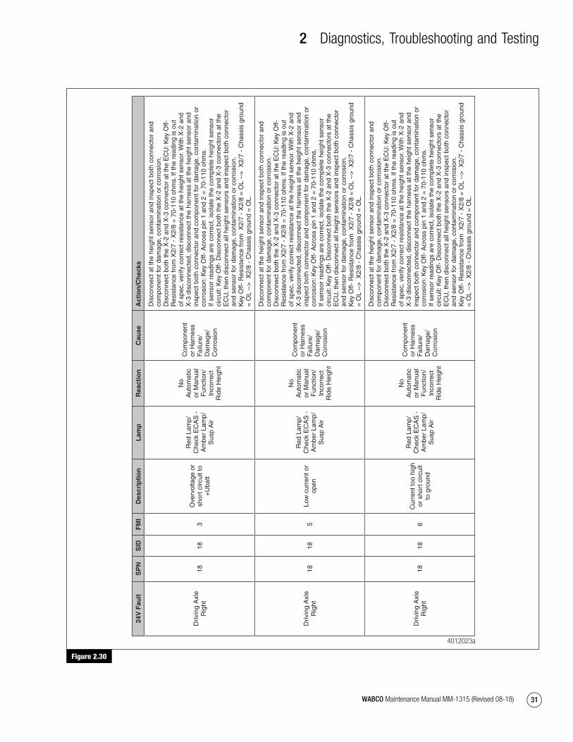
2 Diagnostics, Troubleshooting and Testing
31WABCO Maintenance Manual MM-1315 (Revised 08-18)
Figure 2.30
Figure 2.30
24V
Fau
ltS
PN
SID
FM
ID
escr
ipti
on
Lam
pR
eact
ion
Cau
seA
ctio
n/C
hec
ks
Driv
ing
Axl
e R
ight
1818
3O
verv
olta
ge o
r sh
ort c
ircui
t to
+U
batt
Red
Lam
p/
Che
ck E
CA
S -
A
mbe
r La
mp/
Sus
p A
ir
No
Aut
omat
ic
or M
anua
l F
unct
ion/
In
corr
ect
Rid
e H
eigh
t
Com
pone
nt
or H
arne
ss
Failu
re/
Dam
age/
C
orro
sion
Dis
conn
ect a
t the
hei
ght s
enso
r an
d in
spec
t bot
h co
nnec
tor
and
com
pone
nt fo
r da
mag
e, c
onta
min
atio
n or
cor
rosi
on.
Dis
conn
ect b
oth
the
X-2
and
X-3
con
nect
or a
t the
EC
U: K
ey O
ff-
Res
ista
nce
from
X2/
7 -
X2/
8 =
70-
110
ohm
s. If
the
read
ing
is o
ut
of s
pec,
ver
ify c
orre
ct r
esis
tanc
e at
the
heig
ht s
enso
r. W
ith X
-2 a
nd
X-3
dis
conn
ecte
d, d
isco
nnec
t the
har
ness
at t
he h
eigh
t sen
sor
and
insp
ect b
oth
conn
ecto
r an
d co
mpo
nent
for
dam
age,
con
tam
inat
ion
or
corr
osio
n: K
ey O
ff- A
cros
s pi
n 1
and
2 =
70-
110
ohm
s.
If se
nsor
rea
ding
s ar
e co
rrec
t, is
olat
e th
e co
mpl
ete
heig
ht s
enso
r ci
rcui
t: K
ey O
ff- D
isco
nnec
t bot
h th
e X
-2 a
nd X
-3 c
onne
ctor
s at
the
EC
U, t
hen
disc
onne
ct a
ll he
ight
sen
sors
and
insp
ect b
oth
conn
ecto
r an
d se
nsor
for
dam
age,
con
tam
inat
ion
or c
orro
sion
.
Key
Off-
Res
ista
nce
from
X2/
7 -
X2/
8 =
OL
-->
X2/
7 -
Cha
ssis
gro
und
= O
L --
> X
2/8
- C
hass
is g
roun
d =
OL.
Driv
ing
Axl
e R
ight
1818
5Lo
w c
urre
nt o
r op
en
Red
Lam
p/
Che
ck E
CA
S -
A
mbe
r La
mp/
Sus
p A
ir
No
Aut
omat
ic
or M
anua
l F
unct
ion/
In
corr
ect
Rid
e H
eigh
t
Com
pone
nt
or H
arne
ss
Failu
re/
Dam
age/
C
orro
sion
Dis
conn
ect a
t the
hei
ght s
enso
r an
d in
spec
t bot
h co
nnec
tor
and
com
pone
nt fo
r da
mag
e, c
onta
min
atio
n or
cor
rosi
on.
Dis
conn
ect b
oth
the
X-2
and
X-3
con
nect
or a
t the
EC
U: K
ey O
ff-
Res
ista
nce
from
X2/
7 -
X2/
8 =
70-
110
ohm
s. If
the
read
ing
is o
ut
of s
pec,
ver
ify c
orre
ct r
esis
tanc
e at
the
heig
ht s
enso
r. W
ith X
-2 a
nd
X-3
dis
conn
ecte
d, d
isco
nnec
t the
har
ness
at t
he h
eigh
t sen
sor
and
insp
ect b
oth
conn
ecto
r an
d co
mpo
nent
for
dam
age,
con
tam
inat
ion
or
corr
osio
n: K
ey O
ff- A
cros
s pi
n 1
and
2 =
70-
110
ohm
s.
If se
nsor
rea
ding
s ar
e co
rrec
t, is
olat
e th
e co
mpl
ete
heig
ht s
enso
r ci
rcui
t: K
ey O
ff- D
isco
nnec
t bot
h th
e X
-2 a
nd X
-3 c
onne
ctor
s at
the
EC
U, t
hen
disc
onne
ct a
ll he
ight
sen
sors
and
insp
ect b
oth
conn
ecto
r an
d se
nsor
for
dam
age,
con
tam
inat
ion
or c
orro
sion
.
Key
Off-
Res
ista
nce
from
X2/
7 -
X2/
8 =
OL
-->
X2/
7 -
Cha
ssis
gro
und
= O
L --
> X
2/8
- C
hass
is g
roun
d =
OL.
Driv
ing
Axl
e R
ight
1818
6C
urre
nt to
o hi
gh
or s
hort
circ
uit
to g
roun
d
Red
Lam
p/
Che
ck E
CA
S -
A
mbe
r La
mp/
Sus
p A
ir
No
Aut
omat
ic
or M
anua
l F
unct
ion/
In
corr
ect
Rid
e H
eigh
t
Com
pone
nt
or H
arne
ss
Failu
re/
Dam
age/
C
orro
sion
Dis
conn
ect a
t the
hei
ght s
enso
r an
d in
spec
t bot
h co
nnec
tor
and
com
pone
nt fo
r da
mag
e, c
onta
min
atio
n or
cor
rosi
on.
Dis
conn
ect b
oth
the
X-2
and
X-3
con
nect
or a
t the
EC
U: K
ey O
ff-
Res
ista
nce
from
X2/
7 -
X2/
8 =
70-
110
ohm
s. If
the
read
ing
is o
ut
of s
pec,
ver
ify c
orre
ct r
esis
tanc
e at
the
heig
ht s
enso
r. W
ith X
-2 a
nd
X-3
dis
conn
ecte
d, d
isco
nnec
t the
har
ness
at t
he h
eigh
t sen
sor
and
insp
ect b
oth
conn
ecto
r an
d co
mpo
nent
for
dam
age,
con
tam
inat
ion
or
corr
osio
n: K
ey O
ff- A
cros
s pi
n 1
and
2 =
70-
110
ohm
s.
If se
nsor
rea
ding
s ar
e co
rrec
t, is
olat
e th
e co
mpl
ete
heig
ht s
enso
r ci
rcui
t: K
ey O
ff- D
isco
nnec
t bot
h th
e X
-2 a
nd X
-3 c
onne
ctor
s at
the
EC
U, t
hen
disc
onne
ct a
ll he
ight
sen
sors
and
insp
ect b
oth
conn
ecto
r an
d se
nsor
for
dam
age,
con
tam
inat
ion
or c
orro
sion
.
Key
Off-
Res
ista
nce
from
X2/
7 -
X2/
8 =
OL
-->
X2/
7 -
Cha
ssis
gro
und
= O
L --
> X
2/8
- C
hass
is g
roun
d =
OL.
4012023a
mm1315.bk.fm Page 31 Tuesday, July 9, 2019 7:23 PM
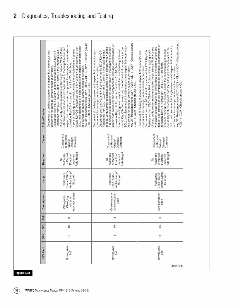
2 Diagnostics, Troubleshooting and Testing
32 WABCO Maintenance Manual MM-1315 (Revised 08-18)
Figure 2.31
Figure 2.31
24V
Fau
ltS
PN
SID
FM
ID
escr
ipti
on
Lam
pR
eact
ion
Cau
seA
ctio
n/C
hec
ks
Driv
ing
Axl
e Le
ft 19
192
Val
ue ju
mp/
Cha
ngin
g va
lues
or
inco
rrec
t val
ues
Red
Lam
p/
Che
ck E
CA
S -
A
mbe
r La
mp/
Sus
p A
ir
No
Aut
omat
ic
or M
anua
l F
unct
ion/
In
corr
ect
Rid
e H
eigh
t
Com
pone
nt
or H
arne
ss
Failu
re/
Dam
age/
C
orro
sion
Dis
conn
ect a
t the
hei
ght s
enso
r an
d in
spec
t bot
h co
nnec
tor
and
com
pone
nt fo
r da
mag
e, c
onta
min
atio
n or
cor
rosi
on.
Dis
conn
ect b
oth
the
X-2
and
X-3
con
nect
or a
t the
EC
U: K
ey O
ff-
Res
ista
nce
from
X2/
7 -
X2/
9 =
70-
110
ohm
s. If
the
read
ing
is o
ut
of s
pec,
ver
ify c
orre
ct r
esis
tanc
e at
the
heig
ht s
enso
r. W
ith X
-2 a
nd
X-3
dis
conn
ecte
d, d
isco
nnec
t the
har
ness
at t
he h
eigh
t sen
sor
and
insp
ect b
oth
conn
ecto
r an
d co
mpo
nent
for
dam
age,
con
tam
inat
ion
or
corr
osio
n: K
ey O
ff- A
cros
s pi
n 1
and
2 =
70-
110
ohm
s.
If se
nsor
rea
ding
s ar
e co
rrec
t, is
olat
e th
e co
mpl
ete
heig
ht s
enso
r ci
rcui
t: K
ey O
ff- D
isco
nnec
t bot
h th
e X
-2 a
nd X
-3 c
onne
ctor
s at
the
EC
U, t
hen
disc
onne
ct a
ll he
ight
sen
sors
and
insp
ect b
oth
conn
ecto
r an
d se
nsor
for
dam
age,
con
tam
inat
ion
or c
orro
sion
.
Key
Off-
Res
ista
nce
from
X2/
7 -
X2/
9 =
OL
-->
X2/
7 -
Cha
ssis
gro
und
= O
L --
> X
2/9
- C
hass
is g
roun
d =
OL.
Driv
ing
Axl
e Le
ft 19
193
Ove
rvol
tage
or
shor
t circ
uit t
o +
Uba
tt
Red
Lam
p/
Che
ck E
CA
S -
A
mbe
r La
mp/
Sus
p A
ir
No
Aut
omat
ic
or M
anua
l F
unct
ion/
In
corr
ect
Rid
e H
eigh
t
Com
pone
nt
or H
arne
ss
Failu
re/
Dam
age/
C
orro
sion
Dis
conn
ect a
t the
hei
ght s
enso
r an
d in
spec
t bot
h co
nnec
tor
and
com
pone
nt fo
r da
mag
e, c
onta
min
atio
n or
cor
rosi
on.
Dis
conn
ect b
oth
the
X-2
and
X-3
con
nect
or a
t the
EC
U: K
ey O
ff-
Res
ista
nce
from
X2/
7 -
X2/
9 =
70-
110
ohm
s. If
the
read
ing
is o
ut
of s
pec,
ver
ify c
orre
ct r
esis
tanc
e at
the
heig
ht s
enso
r. W
ith X
-2 a
nd
X-3
dis
conn
ecte
d, d
isco
nnec
t the
har
ness
at t
he h
eigh
t sen
sor
and
insp
ect b
oth
conn
ecto
r an
d co
mpo
nent
for
dam
age,
con
tam
inat
ion
or
corr
osio
n: K
ey O
ff- A
cros
s pi
n 1
and
2 =
70-
110
ohm
s If
sens
or r
eadi
ngs
are
corr
ect,
isol
ate
the
com
plet
e he
ight
sen
sor
circ
uit:
Key
Off-
Dis
conn
ect b
oth
the
X-2
and
X-3
con
nect
ors
at th
e E
CU
, the
n di
scon
nect
all
heig
ht s
enso
rs a
nd in
spec
t bot
h co
nnec
tor
and
sens
or fo
r da
mag
e, c
onta
min
atio
n or
cor
rosi
on.
K
ey O
ff- R
esis
tanc
e fr
om X
2/7
- X
2/9
= O
L --
> X
2/7
- C
hass
is g
roun
d =
OL
-->
X2/
9 -
Cha
ssis
gro
und
= O
L.
Driv
ing
Axl
e Le
ft 19
195
Low
cur
rent
or
open
Red
Lam
p/
Che
ck E
CA
S -
A
mbe
r La
mp/
Sus
p A
ir
No
Aut
omat
ic
or M
anua
l F
unct
ion/
In
corr
ect
Rid
e H
eigh
t
Com
pone
nt
or H
arne
ss
Failu
re/
Dam
age/
C
orro
sion
Dis
conn
ect a
t the
hei
ght s
enso
r an
d in
spec
t bot
h co
nnec
tor
and
com
pone
nt fo
r da
mag
e, c
onta
min
atio
n or
cor
rosi
on.
Dis
conn
ect b
oth
the
X-2
and
X-3
con
nect
or a
t the
EC
U: K
ey O
ff-
Res
ista
nce
from
X2/
7 -
X2/
9 =
70-
110
ohm
s. If
the
read
ing
is o
ut
of s
pec,
ver
ify c
orre
ct r
esis
tanc
e at
the
heig
ht s
enso
r. W
ith X
-2 a
nd
X-3
dis
conn
ecte
d, d
isco
nnec
t the
har
ness
at t
he h
eigh
t sen
sor
and
insp
ect b
oth
conn
ecto
r an
d co
mpo
nent
for
dam
age,
con
tam
inat
ion
or
corr
osio
n: K
ey O
ff- A
cros
s pi
n 1
and
2 =
70-
110
ohm
s.
If se
nsor
rea
ding
s ar
e co
rrec
t, is
olat
e th
e co
mpl
ete
heig
ht s
enso
r ci
rcui
t: K
ey O
ff- D
isco
nnec
t bot
h th
e X
-2 a
nd X
-3 c
onne
ctor
s at
the
EC
U, t
hen
disc
onne
ct a
ll he
ight
sen
sors
and
insp
ect b
oth
conn
ecto
r an
d se
nsor
for
dam
age,
con
tam
inat
ion
or c
orro
sion
.
Key
Off-
Res
ista
nce
from
X2/
7 -
X2/
9 =
OL
-->
X2/
7 -
Cha
ssis
gro
und
= O
L --
> X
2/9
- C
hass
is g
roun
d =
OL.
4012024a
mm1315.bk.fm Page 32 Tuesday, July 9, 2019 7:23 PM

2 Diagnostics, Troubleshooting and Testing
33WABCO Maintenance Manual MM-1315 (Revised 08-18)
Figure 2.32
Figure 2.32
24V
Fau
ltS
PN
SID
FM
ID
escr
ipti
on
Lam
pR
eact
ion
Cau
seA
ctio
n/C
hec
ks
Driv
ing
Axl
e Le
ft 19
196
Cur
rent
too
high
or
sho
rt c
ircui
t to
gro
und
Red
Lam
p/
Che
ck E
CA
S -
A
mbe
r La
mp/
Sus
p A
ir
No
Aut
omat
ic
or M
anua
l F
unct
ion/
In
corr
ect
Rid
e H
eigh
t
Com
pone
nt
or H
arne
ss
Failu
re/
Dam
age/
C
orro
sion
Dis
conn
ect a
t the
hei
ght s
enso
r an
d in
spec
t bot
h co
nnec
tor
and
com
pone
nt fo
r da
mag
e, c
onta
min
atio
n or
cor
rosi
on.
Dis
conn
ect b
oth
the
X-2
and
X-3
con
nect
or a
t the
EC
U: K
ey O
ff-
Res
ista
nce
from
X2/
7 -
X2/
9 =
70-
110
ohm
s. If
the
read
ing
is o
ut o
f sp
ec, v
erify
cor
rect
res
ista
nce
at th
e he
ight
sen
sor.
With
X-2
and
X-3
di
scon
nect
ed, d
isco
nnec
t the
har
ness
at t
he h
eigh
t sen
sor
and
insp
ect
both
con
nect
or a
nd c
ompo
nent
for
dam
age,
con
tam
inat
ion
or c
orro
sion
: K
ey O
ff- A
cros
s pi
n 1
and
2 =
70-
110
ohm
s.
If se
nsor
rea
ding
s ar
e co
rrec
t, is
olat
e th
e co
mpl
ete
heig
ht s
enso
r ci
rcui
t: K
ey O
ff- D
isco
nnec
t bot
h th
e X
-2 a
nd X
-3 c
onne
ctor
s at
the
EC
U, t
hen
disc
onne
ct a
ll he
ight
sen
sors
and
insp
ect b
oth
conn
ecto
r an
d se
nsor
for
dam
age,
con
tam
inat
ion
or c
orro
sion
.
Key
Off-
Res
ista
nce
from
X2/
7 -
X2/
9 =
OL
-->
X2/
7 -
Cha
ssis
gro
und
=
OL
-->
X2/
9 -
Cha
ssis
gro
und
= O
L.
Pre
ssu
re S
enso
rs
Fron
t Axl
e22
223
Ove
rvol
tage
or
shor
t circ
uit t
o +
Uba
tt
Red
Lam
p/
Che
ck E
CA
S
Inco
rrec
t P
ress
ure
Rea
ding
/ O
ver
or
Und
er
Infla
tion
of
Air
Bag
Com
pone
nt
or H
arne
ss
Failu
re/
Dam
age/
C
orro
sion
Dis
conn
ect a
t the
sen
sor
and
insp
ect b
oth
conn
ecto
r an
d co
mpo
nent
for
dam
age,
con
tam
inat
ion
or c
orro
sion
. K
ey O
n- C
heck
for
DC
vol
tage
from
pin
1 -
2 o
n th
e se
nsor
con
nect
or =
8
- 30
v.
Key
Off-
Dis
conn
ect
pres
sure
sen
sor
and
disc
onne
ct b
oth
the
X-2
and
X
-3 c
onne
ctor
s at
the
EC
U c
heck
res
ista
nce
from
X2/
7 -
chas
sis
grou
nd
= O
L --
> X
2/1
- ch
assi
s gr
ound
= O
L --
> X
2/3
- ch
assi
s gr
ound
= O
L.
Key
Off-
Che
ck X
2/7
- X
2/1
= O
L --
> X
2/7
- X
2/3
= O
L --
> X
2/1
- X
2/3
=
OL.
Fron
t Axl
e22
225
Low
cur
rent
or
open
Red
Lam
p/
Che
ck E
CA
S
Inco
rrec
t P
ress
ure
Rea
ding
/ O
ver
or
Und
er
Infla
tion
of
Air
Bag
Com
pone
nt
or H
arne
ss
Failu
re/
Dam
age/
C
orro
sion
Dis
conn
ect a
t the
sen
sor
and
insp
ect b
oth
conn
ecto
r an
d co
mpo
nent
for
dam
age,
con
tam
inat
ion
or c
orro
sion
. K
ey O
n- C
heck
for
DC
vol
tage
from
pin
1 -
2 o
n th
e se
nsor
con
nect
or =
8
- 30
v.
Key
Off-
Dis
conn
ect
pres
sure
sen
sor
and
disc
onne
ct b
oth
the
X-2
and
X
-3 c
onne
ctor
s at
the
EC
U c
heck
res
ista
nce
from
X2/
7 -
chas
sis
grou
nd
= O
L --
> X
2/1
- ch
assi
s gr
ound
= O
L --
> X
2/3
- ch
assi
s gr
ound
= O
L.
Key
Off-
Che
ck X
2/7
- X
2/1
= O
L --
> X
2/7
- X
2/3
= O
L --
> X
2/1
- X
2/3
=
OL.
Fron
t Axl
e22
226
Cur
rent
too
high
or
sho
rt c
ircui
t to
gro
und
Red
Lam
p/
Che
ck E
CA
S
Inco
rrec
t P
ress
ure
Rea
ding
/ O
ver
or
Und
er
Infla
tion
of
Air
Bag
Com
pone
nt
or H
arne
ss
Failu
re/
Dam
age/
C
orro
sion
Dis
conn
ect a
t the
sen
sor
and
insp
ect b
oth
conn
ecto
r an
d co
mpo
nent
for
dam
age,
con
tam
inat
ion
or c
orro
sion
. K
ey O
n- C
heck
for
DC
vol
tage
from
pin
1 -
2 o
n th
e se
nsor
con
nect
or =
8
- 30
v.
Key
Off-
Dis
conn
ect
pres
sure
sen
sor
and
disc
onne
ct b
oth
the
X-2
and
X
-3 c
onne
ctor
s at
the
EC
U c
heck
res
ista
nce
from
X2/
7 -
chas
sis
grou
nd
= O
L --
> X
2/1
- ch
assi
s gr
ound
= O
L --
> X
2/3
- ch
assi
s gr
ound
= O
L.
Key
Off-
Che
ck X
2/7
- X
2/1
= O
L --
> X
2/7
- X
2/3
= O
L --
> X
2/1
- X
2/3
=
OL.
Driv
ing
Axl
e R
ight
2424
3O
verv
olta
ge o
r sh
ort c
ircui
t to
+U
batt
Red
Lam
p/
Che
ck E
CA
S
Inco
rrec
t P
ress
ure
Rea
ding
/ O
ver
or
Und
er
Infla
tion
of
Air
Bag
Com
pone
nt
or H
arne
ss
Failu
re/
Dam
age/
C
orro
sion
Dis
conn
ect a
t the
sen
sor
and
insp
ect b
oth
conn
ecto
r an
d co
mpo
nent
for
dam
age,
con
tam
inat
ion
or c
orro
sion
. K
ey O
n- C
heck
for
DC
vol
tage
from
pin
1 -
2 o
n th
e se
nsor
con
nect
or =
8
- 30
v.
Key
Off-
Dis
conn
ect
pres
sure
sen
sor
and
disc
onne
ct b
oth
the
X-2
and
X
-3 c
onne
ctor
s at
the
EC
U c
heck
res
ista
nce
from
X2/
7 -
chas
sis
grou
nd
= O
L --
> X
2/1
- ch
assi
s gr
ound
= O
L --
> X
2/2
- ch
assi
s gr
ound
= O
L.
Key
Off-
Che
ck X
2/7
- X
2/1
= O
L --
> X
2/7
- X
2/3
= O
L --
> X
2/1
- X
2/2
=
OL.
4012025a
mm1315.bk.fm Page 33 Tuesday, July 9, 2019 7:23 PM
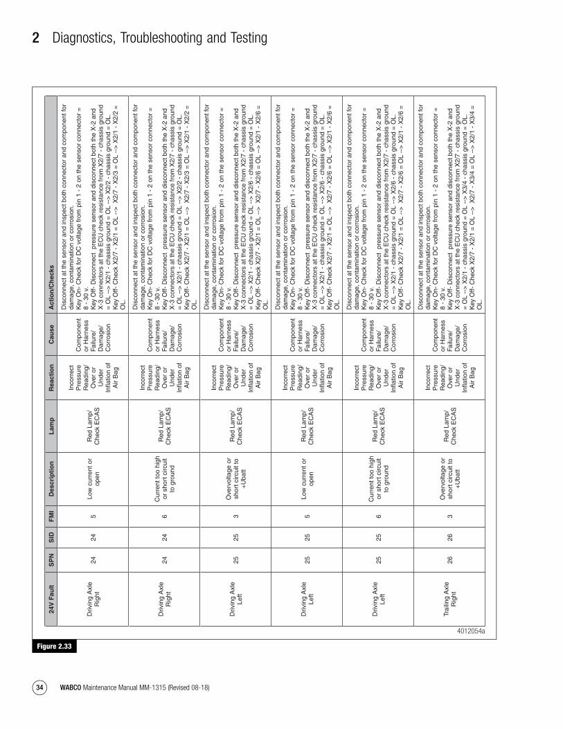
2 Diagnostics, Troubleshooting and Testing
34 WABCO Maintenance Manual MM-1315 (Revised 08-18)
Figure 2.33
Figure 2.33
24V
Fau
ltS
PN
SID
FM
ID
escr
ipti
on
Lam
pR
eact
ion
Cau
seA
ctio
n/C
hec
ks
Driv
ing
Axl
e R
ight
2424
5Lo
w c
urre
nt o
r op
enR
ed L
amp/
C
heck
EC
AS
Inco
rrec
t P
ress
ure
Rea
ding
/ O
ver
or
Und
er
Infla
tion
of
Air
Bag
Com
pone
nt
or H
arne
ss
Failu
re/
Dam
age/
C
orro
sion
Dis
conn
ect a
t the
sen
sor
and
insp
ect b
oth
conn
ecto
r an
d co
mpo
nent
for
dam
age,
con
tam
inat
ion
or c
orro
sion
. K
ey O
n- C
heck
for
DC
vol
tage
from
pin
1 -
2 o
n th
e se
nsor
con
nect
or =
8
- 30
v.
Key
Off-
Dis
conn
ect
pres
sure
sen
sor
and
disc
onne
ct b
oth
the
X-2
and
X
-3 c
onne
ctor
s at
the
EC
U c
heck
res
ista
nce
from
X2/
7 -
chas
sis
grou
nd
= O
L --
> X
2/1
- ch
assi
s gr
ound
= O
L --
> X
2/2
- ch
assi
s gr
ound
= O
L.
Key
Off-
Che
ck X
2/7
- X
2/1
= O
L --
> X
2/7
- X
2/3
= O
L --
> X
2/1
- X
2/2
=
OL.
Driv
ing
Axl
e R
ight
2424
6C
urre
nt to
o hi
gh
or s
hort
circ
uit
to g
roun
d
Red
Lam
p/
Che
ck E
CA
S
Inco
rrec
t P
ress
ure
Rea
ding
/ O
ver
or
Und
er
Infla
tion
of
Air
Bag
Com
pone
nt
or H
arne
ss
Failu
re/
Dam
age/
C
orro
sion
Dis
conn
ect a
t the
sen
sor
and
insp
ect b
oth
conn
ecto
r an
d co
mpo
nent
for
dam
age,
con
tam
inat
ion
or c
orro
sion
. K
ey O
n- C
heck
for
DC
vol
tage
from
pin
1 -
2 o
n th
e se
nsor
con
nect
or =
8
- 30
v.
Key
Off-
Dis
conn
ect
pres
sure
sen
sor
and
disc
onne
ct b
oth
the
X-2
and
X
-3 c
onne
ctor
s at
the
EC
U c
heck
res
ista
nce
from
X2/
7 -
chas
sis
grou
nd
= O
L --
> X
2/1
- ch
assi
s gr
ound
= O
L --
> X
2/2
- ch
assi
s gr
ound
= O
L.
Key
Off-
Che
ck X
2/7
- X
2/1
= O
L --
> X
2/7
- X
2/3
= O
L --
> X
2/1
- X
2/2
=
OL.
Driv
ing
Axl
e Le
ft25
253
Ove
rvol
tage
or
shor
t circ
uit t
o +
Uba
tt
Red
Lam
p/
Che
ck E
CA
S
Inco
rrec
t P
ress
ure
Rea
ding
/ O
ver
or
Und
er
Infla
tion
of
Air
Bag
Com
pone
nt
or H
arne
ss
Failu
re/
Dam
age/
C
orro
sion
Dis
conn
ect a
t the
sen
sor
and
insp
ect b
oth
conn
ecto
r an
d co
mpo
nent
for
dam
age,
con
tam
inat
ion
or c
orro
sion
. K
ey O
n- C
heck
for
DC
vol
tage
from
pin
1 -
2 o
n th
e se
nsor
con
nect
or =
8
- 30
v.
Key
Off-
Dis
conn
ect
pres
sure
sen
sor
and
disc
onne
ct b
oth
the
X-2
and
X
-3 c
onne
ctor
s at
the
EC
U c
heck
res
ista
nce
from
X2/
7 -
chas
sis
grou
nd
= O
L --
> X
2/1
- ch
assi
s gr
ound
= O
L --
> X
2/6
- ch
assi
s gr
ound
= O
L.
Key
Off-
Che
ck X
2/7
- X
2/1
= O
L --
> X
2/7
- X
2/6
= O
L --
> X
2/1
- X
2/6
=
OL.
Driv
ing
Axl
e Le
ft25
255
Low
cur
rent
or
open
Red
Lam
p/
Che
ck E
CA
S
Inco
rrec
t P
ress
ure
Rea
ding
/ O
ver
or
Und
er
Infla
tion
of
Air
Bag
Com
pone
nt
or H
arne
ss
Failu
re/
Dam
age/
C
orro
sion
Dis
conn
ect a
t the
sen
sor
and
insp
ect b
oth
conn
ecto
r an
d co
mpo
nent
for
dam
age,
con
tam
inat
ion
or c
orro
sion
. K
ey O
n- C
heck
for
DC
vol
tage
from
pin
1 -
2 o
n th
e se
nsor
con
nect
or =
8
- 30
v.
Key
Off-
Dis
conn
ect
pres
sure
sen
sor
and
disc
onne
ct b
oth
the
X-2
and
X
-3 c
onne
ctor
s at
the
EC
U c
heck
res
ista
nce
from
X2/
7 -
chas
sis
grou
nd
= O
L --
> X
2/1
- ch
assi
s gr
ound
= O
L --
> X
2/6
- ch
assi
s gr
ound
= O
L.
Key
Off-
Che
ck X
2/7
- X
2/1
= O
L --
> X
2/7
- X
2/6
= O
L --
> X
2/1
- X
2/6
=
OL.
Driv
ing
Axl
e Le
ft25
256
Cur
rent
too
high
or
sho
rt c
ircui
t to
gro
und
Red
Lam
p/
Che
ck E
CA
S
Inco
rrec
t P
ress
ure
Rea
ding
/ O
ver
or
Und
er
Infla
tion
of
Air
Bag
Com
pone
nt
or H
arne
ss
Failu
re/
Dam
age/
C
orro
sion
Dis
conn
ect a
t the
sen
sor
and
insp
ect b
oth
conn
ecto
r an
d co
mpo
nent
for
dam
age,
con
tam
inat
ion
or c
orro
sion
. K
ey O
n- C
heck
for
DC
vol
tage
from
pin
1 -
2 o
n th
e se
nsor
con
nect
or =
8
- 30
v.
Key
Off-
Dis
conn
ect
pres
sure
sen
sor
and
disc
onne
ct b
oth
the
X-2
and
X
-3 c
onne
ctor
s at
the
EC
U c
heck
res
ista
nce
from
X2/
7 -
chas
sis
grou
nd
= O
L --
> X
2/1
- ch
assi
s gr
ound
= O
L --
> X
2/6
- ch
assi
s gr
ound
= O
L.
Key
Off-
Che
ck X
2/7
- X
2/1
= O
L --
> X
2/7
- X
2/6
= O
L --
> X
2/1
- X
2/6
=
OL.
Trai
ling
Axl
e R
ight
2626
3O
verv
olta
ge o
r sh
ort c
ircui
t to
+U
batt
Red
Lam
p/
Che
ck E
CA
S
Inco
rrec
t P
ress
ure
Rea
ding
/ O
ver
or
Und
er
Infla
tion
of
Air
Bag
Com
pone
nt
or H
arne
ss
Failu
re/
Dam
age/
C
orro
sion
Dis
conn
ect a
t the
sen
sor
and
insp
ect b
oth
conn
ecto
r an
d co
mpo
nent
for
dam
age,
con
tam
inat
ion
or c
orro
sion
. K
ey O
n- C
heck
for
DC
vol
tage
from
pin
1 -
2 o
n th
e se
nsor
con
nect
or =
8
- 30
v.
Key
Off-
Dis
conn
ect
pres
sure
sen
sor
and
disc
onne
ct b
oth
the
X-2
and
X
-3 c
onne
ctor
s at
the
EC
U c
heck
res
ista
nce
from
X2/
7 -
chas
sis
grou
nd
= O
L --
> X
2/1
- ch
assi
s gr
ound
= O
L --
> X
3/4
- ch
assi
s gr
ound
= O
L.
Key
Off-
Che
ck X
2/7
- X
2/1
= O
L --
> X
2/7
- X
3/4
= O
L --
> X
2/1
- X
3/4
=
OL.
4012054a
mm1315.bk.fm Page 34 Tuesday, July 9, 2019 7:23 PM
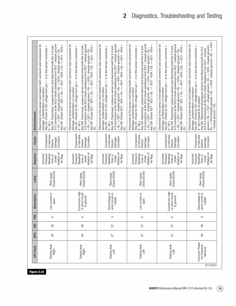
2 Diagnostics, Troubleshooting and Testing
35WABCO Maintenance Manual MM-1315 (Revised 08-18)
Figure 2.34
Figure 2.34
24V
Fau
ltS
PN
SID
FM
ID
escr
ipti
on
Lam
pR
eact
ion
Cau
seA
ctio
n/C
hec
ks
Trai
ling
Axl
e R
ight
2626
5Lo
w c
urre
nt o
r op
enR
ed L
amp/
C
heck
EC
AS
Inco
rrec
t P
ress
ure
Rea
ding
/ O
ver
or
Und
er
Infla
tion
of
Air
Bag
Com
pone
nt
or H
arne
ss
Failu
re/
Dam
age/
C
orro
sion
Dis
conn
ect a
t the
sen
sor
and
insp
ect b
oth
conn
ecto
r an
d co
mpo
nent
for
dam
age,
con
tam
inat
ion
or c
orro
sion
. K
ey O
n- C
heck
for
DC
vol
tage
from
pin
1 -
2 o
n th
e se
nsor
con
nect
or =
8
- 30
v.
Key
Off-
Dis
conn
ect
pres
sure
sen
sor
and
disc
onne
ct b
oth
the
X-2
and
X
-3 c
onne
ctor
s at
the
EC
U c
heck
res
ista
nce
from
X2/
7 -
chas
sis
grou
nd
= O
L --
> X
2/1
- ch
assi
s gr
ound
= O
L --
> X
3/4
- ch
assi
s gr
ound
= O
L.
Key
Off-
Che
ck X
2/7
- X
2/1
= O
L --
> X
2/7
- X
3/4
= O
L --
> X
2/1
- X
3/4
=
OL.
Trai
ling
Axl
e R
ight
2626
6C
urre
nt to
o hi
gh
or s
hort
circ
uit
to g
roun
d
Red
Lam
p/
Che
ck E
CA
S
Inco
rrec
t P
ress
ure
Rea
ding
/ O
ver
or
Und
er
Infla
tion
of
Air
Bag
Com
pone
nt
or H
arne
ss
Failu
re/
Dam
age/
C
orro
sion
Dis
conn
ect a
t the
sen
sor
and
insp
ect b
oth
conn
ecto
r an
d co
mpo
nent
for
dam
age,
con
tam
inat
ion
or c
orro
sion
. K
ey O
n- C
heck
for
DC
vol
tage
from
pin
1 -
2 o
n th
e se
nsor
con
nect
or =
8
- 30
v.
Key
Off-
Dis
conn
ect
pres
sure
sen
sor
and
disc
onne
ct b
oth
the
X-2
and
X
-3 c
onne
ctor
s at
the
EC
U c
heck
res
ista
nce
from
X2/
7 -
chas
sis
grou
nd
= O
L --
> X
2/1
- ch
assi
s gr
ound
= O
L --
> X
3/3
- ch
assi
s gr
ound
= O
L.
Key
Off-
Che
ck X
2/7
- X
2/1
= O
L --
> X
2/7
- X
3/3
= O
L --
> X
2/1
- X
3/3
=
OL.
Trai
ling
Axl
e Le
ft27
273
Ove
rvol
tage
or
shor
t circ
uit t
o +
Uba
tt
Red
Lam
p/
Che
ck E
CA
S
Inco
rrec
t P
ress
ure
Rea
ding
/ O
ver
or
Und
er
Infla
tion
of
Air
Bag
Com
pone
nt
or H
arne
ss
Failu
re/
Dam
age/
C
orro
sion
Dis
conn
ect a
t the
sen
sor
and
insp
ect b
oth
conn
ecto
r an
d co
mpo
nent
for
dam
age,
con
tam
inat
ion
or c
orro
sion
. K
ey O
n- C
heck
for
DC
vol
tage
from
pin
1 -
2 o
n th
e se
nsor
con
nect
or =
8
- 30
v.
Key
Off-
Dis
conn
ect
pres
sure
sen
sor
and
disc
onne
ct b
oth
the
X-2
and
X
-3 c
onne
ctor
s at
the
EC
U c
heck
res
ista
nce
from
X2/
7 -
chas
sis
grou
nd
= O
L --
> X
2/1
- ch
assi
s gr
ound
= O
L --
> X
3/4
- ch
assi
s gr
ound
= O
L.
Key
Off-
Che
ck X
2/7
- X
2/1
= O
L --
> X
2/7
- X
3/4
= O
L --
> X
2/1
- X
3/4
=
OL.
Trai
ling
Axl
e Le
ft27
275
Low
cur
rent
or
open
Red
Lam
p/
Che
ck E
CA
S
Inco
rrec
t P
ress
ure
Rea
ding
/ O
ver
or
Und
er
Infla
tion
of
Air
Bag
Com
pone
nt
or H
arne
ss
Failu
re/
Dam
age/
C
orro
sion
Dis
conn
ect a
t the
sen
sor
and
insp
ect b
oth
conn
ecto
r an
d co
mpo
nent
for
dam
age,
con
tam
inat
ion
or c
orro
sion
. K
ey O
n- C
heck
for
DC
vol
tage
from
pin
1 -
2 o
n th
e se
nsor
con
nect
or =
8
- 30
v.
Key
Off-
Dis
conn
ect
pres
sure
sen
sor
and
disc
onne
ct b
oth
the
X-2
and
X
-3 c
onne
ctor
s at
the
EC
U c
heck
res
ista
nce
from
X2/
7 -
chas
sis
grou
nd
= O
L --
> X
2/1
- ch
assi
s gr
ound
= O
L --
> X
3/4
- ch
assi
s gr
ound
= O
L.
Key
Off-
Che
ck X
2/7
- X
2/1
= O
L --
> X
2/7
- X
3/4
= O
L --
> X
2/1
- X
3/4
=
OL.
Trai
ling
Axl
e Le
ft27
276
Cur
rent
too
high
or
sho
rt c
ircui
t to
gro
und
Red
Lam
p/
Che
ck E
CA
S
Inco
rrec
t P
ress
ure
Rea
ding
/ O
ver
or
Und
er
Infla
tion
of
Air
Bag
Com
pone
nt
or H
arne
ss
Failu
re/
Dam
age/
C
orro
sion
Dis
conn
ect a
t the
sen
sor
and
insp
ect b
oth
conn
ecto
r an
d co
mpo
nent
for
dam
age,
con
tam
inat
ion
or c
orro
sion
. K
ey O
n- C
heck
for
DC
vol
tage
from
pin
1 -
2 o
n th
e se
nsor
con
nect
or =
8
- 30
v.
Key
Off-
Dis
conn
ect
pres
sure
sen
sor
and
disc
onne
ct b
oth
the
X-2
and
X
-3 c
onne
ctor
s at
the
EC
U c
heck
res
ista
nce
from
X2/
7 -
chas
sis
grou
nd
= O
L --
> X
2/1
- ch
assi
s gr
ound
= O
L --
> X
3/4
- ch
assi
s gr
ound
= O
L.
Key
Off-
Che
ck X
2/7
- X
2/1
= O
L --
> X
2/7
- X
3/4
= O
L --
> X
2/1
- X
3/4
=
OL.
Com
mon
Pow
er
for
Pre
ssur
e S
enso
rs46
463
Ove
rvol
tage
or
shor
t circ
uit t
o +
Uba
tt
Red
Lam
p/
Che
ck E
CA
S
Inco
rrec
t P
ress
ure
Rea
ding
/ O
ver
or
Und
er
Infla
tion
of
Air
Bag
Com
pone
nt
or H
arne
ss
Failu
re/
Dam
age/
C
orro
sion
Dis
conn
ect a
t the
sen
sor
and
insp
ect b
oth
conn
ecto
r an
d co
mpo
nent
for
dam
age,
con
tam
inat
ion
or c
orro
sion
. K
ey O
n- C
heck
for
DC
vol
tage
from
pin
1 -
2 o
n th
e se
nsor
con
nect
or =
8
- 30
v (
repe
at fo
r al
l axl
es).
Key
Off-
Dis
conn
ect a
ll pr
essu
re s
enso
rs a
nd d
isco
nnec
t bot
h th
e X
-2
and
X-3
con
nect
ors
at th
e E
CU
che
ck r
esis
tanc
e fr
om X
2/7
- ch
assi
s gr
ound
= O
L --
> X
2/1
- ch
assi
s gr
ound
= O
L --
> X
2/6
- ch
assi
s gr
ound
=
OL
-->
X2/
3-ch
assi
s gr
ound
= O
L --
> X
3/3
- ch
assi
s gr
ound
= O
L --
> X
3/4
- ch
assi
s gr
ound
= O
L.
4012055a
mm1315.bk.fm Page 35 Tuesday, July 9, 2019 7:23 PM
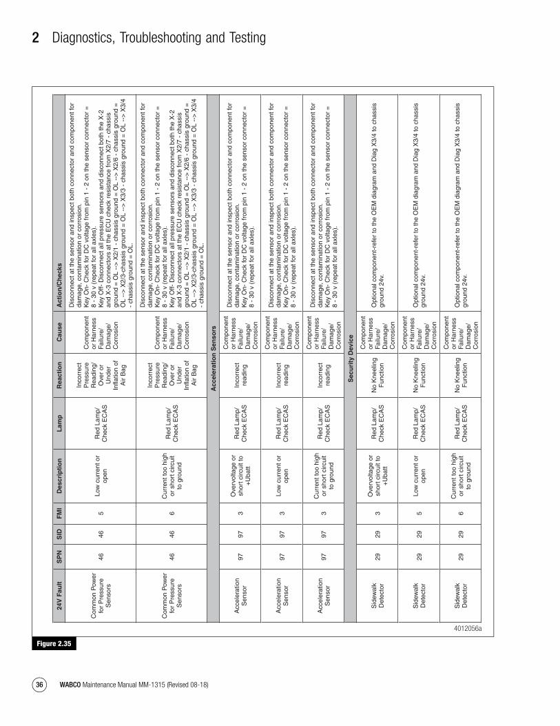
2 Diagnostics, Troubleshooting and Testing
36 WABCO Maintenance Manual MM-1315 (Revised 08-18)
Figure 2.35
Figure 2.35
24V
Fau
ltS
PN
SID
FM
ID
escr
ipti
on
Lam
pR
eact
ion
Cau
seA
ctio
n/C
hec
ks
Com
mon
Pow
er
for
Pre
ssur
e S
enso
rs46
465
Low
cur
rent
or
open
Red
Lam
p/
Che
ck E
CA
S
Inco
rrec
t P
ress
ure
Rea
ding
/ O
ver
or
Und
er
Infla
tion
of
Air
Bag
Com
pone
nt
or H
arne
ss
Failu
re/
Dam
age/
C
orro
sion
Dis
conn
ect a
t the
sen
sor
and
insp
ect b
oth
conn
ecto
r an
d co
mpo
nent
for
dam
age,
con
tam
inat
ion
or c
orro
sion
. K
ey O
n- C
heck
for
DC
vol
tage
from
pin
1 -
2 o
n th
e se
nsor
con
nect
or =
8
- 30
v (
repe
at fo
r al
l axl
es).
Key
Off-
Dis
conn
ect a
ll pr
essu
re s
enso
rs a
nd d
isco
nnec
t bot
h th
e X
-2
and
X-3
con
nect
ors
at th
e E
CU
che
ck r
esis
tanc
e fr
om X
2/7
- ch
assi
s gr
ound
= O
L --
> X
2/1
- ch
assi
s gr
ound
= O
L --
> X
2/6
- ch
assi
s gr
ound
=
OL
-->
X2/
3-ch
assi
s gr
ound
= O
L --
> X
3/3
- ch
assi
s gr
ound
= O
L --
> X
3/4
- ch
assi
s gr
ound
= O
L.
Com
mon
Pow
er
for
Pre
ssur
e S
enso
rs46
466
Cur
rent
too
high
or
sho
rt c
ircui
t to
gro
und
Red
Lam
p/
Che
ck E
CA
S
Inco
rrec
t P
ress
ure
Rea
ding
/ O
ver
or
Und
er
Infla
tion
of
Air
Bag
Com
pone
nt
or H
arne
ss
Failu
re/
Dam
age/
C
orro
sion
Dis
conn
ect a
t the
sen
sor
and
insp
ect b
oth
conn
ecto
r an
d co
mpo
nent
for
dam
age,
con
tam
inat
ion
or c
orro
sion
. K
ey O
n- C
heck
for
DC
vol
tage
from
pin
1 -
2 o
n th
e se
nsor
con
nect
or =
8
- 30
v (
repe
at fo
r al
l axl
es).
Key
Off-
Dis
conn
ect a
ll pr
essu
re s
enso
rs a
nd d
isco
nnec
t bot
h th
e X
-2
and
X-3
con
nect
ors
at th
e E
CU
che
ck r
esis
tanc
e fr
om X
2/7
- ch
assi
s gr
ound
= O
L --
> X
2/1
- ch
assi
s gr
ound
= O
L --
> X
2/6
- ch
assi
s gr
ound
=
OL
-->
X2/
3-ch
assi
s gr
ound
= O
L --
> X
3/3
- ch
assi
s gr
ound
= O
L --
> X
3/4
- ch
assi
s gr
ound
= O
L.
Acc
eler
atio
n S
enso
rs
Acc
eler
atio
n S
enso
r97
973
Ove
rvol
tage
or
shor
t circ
uit t
o +
Uba
tt
Red
Lam
p/
Che
ck E
CA
SIn
corr
ect
read
ing
Com
pone
nt
or H
arne
ss
Failu
re/
Dam
age/
C
orro
sion
Dis
conn
ect a
t the
sen
sor
and
insp
ect b
oth
conn
ecto
r an
d co
mpo
nent
for
dam
age,
con
tam
inat
ion
or c
orro
sion
. K
ey O
n- C
heck
for
DC
vol
tage
from
pin
1 -
2 o
n th
e se
nsor
con
nect
or =
8
- 30
v (
repe
at fo
r al
l axl
es).
Acc
eler
atio
n S
enso
r97
973
Low
cur
rent
or
open
Red
Lam
p/
Che
ck E
CA
SIn
corr
ect
read
ing
Com
pone
nt
or H
arne
ss
Failu
re/
Dam
age/
C
orro
sion
Dis
conn
ect a
t the
sen
sor
and
insp
ect b
oth
conn
ecto
r an
d co
mpo
nent
for
dam
age,
con
tam
inat
ion
or c
orro
sion
. K
ey O
n- C
heck
for
DC
vol
tage
from
pin
1 -
2 o
n th
e se
nsor
con
nect
or =
8
- 30
v (
repe
at fo
r al
l axl
es).
Acc
eler
atio
n S
enso
r97
973
Cur
rent
too
high
or
sho
rt c
ircui
t to
gro
und
Red
Lam
p/
Che
ck E
CA
SIn
corr
ect
read
ing
Com
pone
nt
or H
arne
ss
Failu
re/
Dam
age/
C
orro
sion
Dis
conn
ect a
t the
sen
sor
and
insp
ect b
oth
conn
ecto
r an
d co
mpo
nent
for
dam
age,
con
tam
inat
ion
or c
orro
sion
. K
ey O
n- C
heck
for
DC
vol
tage
from
pin
1 -
2 o
n th
e se
nsor
con
nect
or =
8
- 30
v (
repe
at fo
r al
l axl
es).
Sec
uri
ty D
evic
e
Sid
ewal
k D
etec
tor
2929
3O
verv
olta
ge o
r sh
ort c
ircui
t to
+U
batt
Red
Lam
p/
Che
ck E
CA
SN
o K
neel
ing
Fun
ctio
n
Com
pone
nt
or H
arne
ss
Failu
re/
Dam
age/
C
orro
sion
Opt
iona
l com
pone
nt-r
efer
to th
e O
EM
dia
gram
and
Dia
g X
3/4
to c
hass
is
grou
nd 2
4v.
Sid
ewal
k D
etec
tor
2929
5Lo
w c
urre
nt o
r op
enR
ed L
amp/
C
heck
EC
AS
No
Kne
elin
g F
unct
ion
Com
pone
nt
or H
arne
ss
Failu
re/
Dam
age/
C
orro
sion
Opt
iona
l com
pone
nt-r
efer
to th
e O
EM
dia
gram
and
Dia
g X
3/4
to c
hass
is
grou
nd 2
4v.
Sid
ewal
k D
etec
tor
2929
6C
urre
nt to
o hi
gh
or s
hort
circ
uit
to g
roun
d
Red
Lam
p/
Che
ck E
CA
SN
o K
neel
ing
Fun
ctio
n
Com
pone
nt
or H
arne
ss
Failu
re/
Dam
age/
C
orro
sion
Opt
iona
l com
pone
nt-r
efer
to th
e O
EM
dia
gram
and
Dia
g X
3/4
to c
hass
is
grou
nd 2
4v.
4012056a
mm1315.bk.fm Page 36 Tuesday, July 9, 2019 7:23 PM

2 Diagnostics, Troubleshooting and Testing
37WABCO Maintenance Manual MM-1315 (Revised 08-18)
Figure 2.36
Figure 2.36
24V
Fau
ltS
PN
SID
FM
ID
escr
ipti
on
Lam
pR
eact
ion
Cau
seA
ctio
n/C
hec
ks
So
len
oid
Val
ves
Fron
t Axl
e R
ight
(2
/2 S
olen
oid
Val
ve)
11
3O
verv
olta
ge o
r sh
ort c
ircui
t to
+U
batt
Red
Lam
p/
Che
ck E
CA
S
No
Cha
rgin
g/
Ven
ting
Com
pone
nt
or H
arne
ss
Failu
re/
Dam
age/
C
orro
sion
Dis
conn
ect a
t the
val
ve a
nd in
spec
t bot
h co
nnec
tor
and
com
pone
nt fo
r da
mag
e, c
onta
min
atio
n or
cor
rosi
on.
Key
On-
Ver
ify v
olta
ge o
n th
e ch
assi
s ha
rnes
s fr
om p
in 2
- to
cha
ssis
=
4v -
7v
and
4 -
to c
hass
is =
4v
- 7v
(de
pend
ing
on O
EM
vs
Afte
rmar
ket
inst
alla
tion,
vol
tage
may
be
foun
d on
ly o
n pi
n 2-
3). I
f the
vol
tage
is o
ff,
disc
onne
ct a
ll va
lves
and
re-
chec
k.
With
the
chas
sis
harn
ess
reco
nnec
ted,
dis
conn
ect t
he X
/2 a
nd X
/3
conn
ecto
rs.
Key
Off-
Ver
ify th
e re
sist
ance
from
X2/
15–
X2/
4 =
60-
90 o
hms.
If th
e re
adin
g is
out
of s
pec,
che
ck a
t the
val
ve: R
esis
tanc
e fr
om p
in 2
-3 =
60-
90 o
hms
and
4-3
= 6
0-90
ohm
s.
Key
Off-
With
X/2
- X
/3 E
CU
con
nect
ors
disc
onne
cted
and
the
valv
e di
scon
nect
ed. C
heck
res
ista
nce
to g
roun
d: X
2/4
- ch
assi
s gr
ound
= O
L --
> X
2/15
- c
hass
is g
roun
d =
OL.
K
ey O
ff- W
ith X
/2 -
X/3
EC
U c
onne
ctor
s di
scon
nect
ed a
nd th
e va
lve
disc
onne
cted
. Che
ck r
esis
tanc
e fr
om X
2/4
- X
2/15
=O
L --
> X
2/4
- X
3/2
=O
L --
> X
2/15
- X
3/2
= O
L.
Key
Off-
Che
ck e
ach
pin
on th
e va
lve
to c
hass
is g
roun
d: P
in1-
cha
ssis
gr
ound
= O
L --
> P
in2-
cha
ssis
gro
und
= O
L --
> P
in3-
cha
ssis
gro
und
=
OL
-->
Pin
4- c
hass
is g
roun
d =
OL.
Fron
t Axl
e R
ight
(2
/2 S
olen
oid
Val
ve)
11
5Lo
w c
urre
nt o
r op
enR
ed L
amp/
C
heck
EC
AS
No
Cha
rgin
g/
Ven
ting
Com
pone
nt
or H
arne
ss
Failu
re/
Dam
age/
C
orro
sion
Dis
conn
ect a
t the
val
ve a
nd in
spec
t bot
h co
nnec
tor
and
com
pone
nt fo
r da
mag
e, c
onta
min
atio
n or
cor
rosi
on:
Key
On-
Ver
ify v
olta
ge o
n th
e ch
assi
s ha
rnes
s fr
om p
in 2
- to
cha
ssis
=
4v -
7v
and
4 -
to c
hass
is =
4v
- 7v
(de
pend
ing
on O
EM
vs
Afte
rmar
ket
inst
alla
tion,
vol
tage
may
be
foun
d on
ly o
n pi
n 2-
3). I
f vol
tage
is o
ff,
disc
onne
ct a
ll va
lves
and
re-
chec
k.
With
the
chas
sis
harn
ess
reco
nnec
ted,
dis
conn
ect t
he X
/2 a
nd X
/3
conn
ecto
rs.
Key
Off-
Ver
ify th
e re
sist
ance
from
X2/
15–
X2/
4 =
60-
90 o
hms.
If th
e re
adin
g is
out
of s
pec,
che
ck a
t the
val
ve: R
esis
tanc
e fr
om p
in 2
-3 =
60-
90 o
hms
and
4-3
= 6
0-90
ohm
s.
Key
Off-
With
X/2
- X
/3 E
CU
con
nect
ors
disc
onne
cted
and
the
valv
e di
scon
nect
ed. C
heck
res
ista
nce
to g
roun
d: X
2/4
- ch
assi
s gr
ound
= O
L --
> X
2/15
- c
hass
is g
roun
d =
OL.
K
ey O
ff- W
ith X
/2 -
X/3
EC
U c
onne
ctor
s di
scon
nect
ed a
nd th
e va
lve
disc
onne
cted
. Che
ck r
esis
tanc
e fr
om X
2/4
- X
2/15
=O
L --
> X
2/4
- X
3/2
=O
L --
> X
2/15
- X
3/2
= O
L.
Key
Off-
Che
ck e
ach
pin
on th
e va
lve
to c
hass
is g
roun
d: P
in1-
cha
ssis
gr
ound
= O
L --
> P
in2-
cha
ssis
gro
und
= O
L --
> P
in3-
cha
ssis
gro
und
=
OL
-->
Pin
4- c
hass
is g
roun
d =
OL.
4012057a
mm1315.bk.fm Page 37 Tuesday, July 9, 2019 7:23 PM
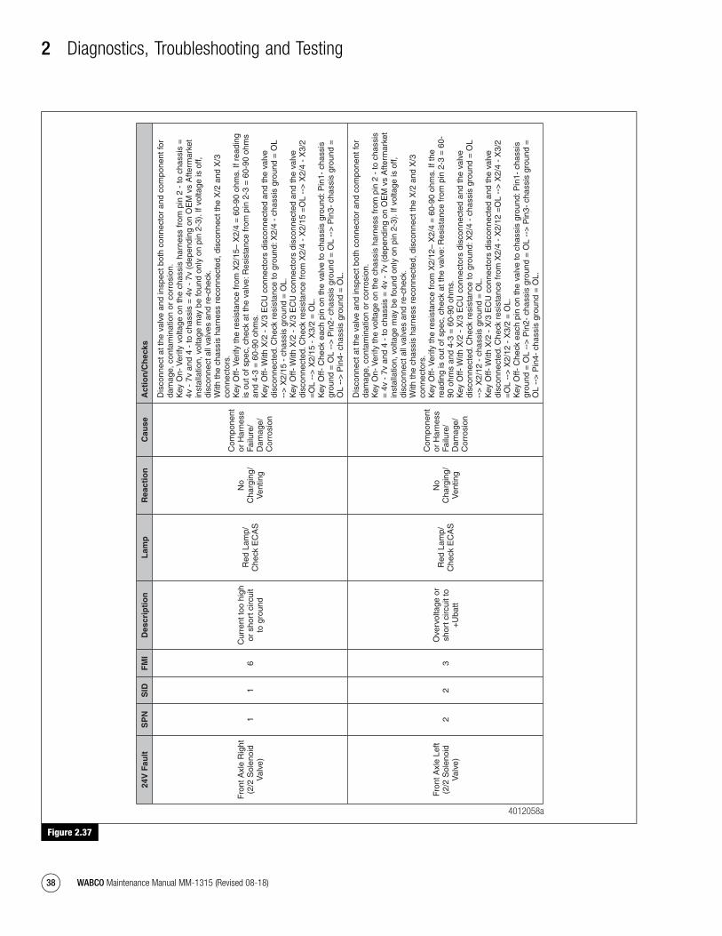
2 Diagnostics, Troubleshooting and Testing
38 WABCO Maintenance Manual MM-1315 (Revised 08-18)
Figure 2.37
Figure 2.37
24V
Fau
ltS
PN
SID
FM
ID
escr
ipti
on
Lam
pR
eact
ion
Cau
seA
ctio
n/C
hec
ks
Fron
t Axl
e R
ight
(2
/2 S
olen
oid
Val
ve)
11
6C
urre
nt to
o hi
gh
or s
hort
circ
uit
to g
roun
d
Red
Lam
p/
Che
ck E
CA
S
No
Cha
rgin
g/
Ven
ting
Com
pone
nt
or H
arne
ss
Failu
re/
Dam
age/
C
orro
sion
Dis
conn
ect a
t the
val
ve a
nd in
spec
t bot
h co
nnec
tor
and
com
pone
nt fo
r da
mag
e, c
onta
min
atio
n or
cor
rosi
on.
Key
On-
Ver
ify v
olta
ge o
n th
e ch
assi
s ha
rnes
s fr
om p
in 2
- to
cha
ssis
=
4v -
7v
and
4 -
to c
hass
is =
4v
- 7v
(de
pend
ing
on O
EM
vs
Afte
rmar
ket
inst
alla
tion,
vol
tage
may
be
foun
d on
ly o
n pi
n 2-
3). I
f vol
tage
is o
ff,
disc
onne
ct a
ll va
lves
and
re-
chec
k.
With
the
chas
sis
harn
ess
reco
nnec
ted,
dis
conn
ect t
he X
/2 a
nd X
/3
conn
ecto
rs.
Key
Off-
Ver
ify th
e re
sist
ance
from
X2/
15–
X2/
4 =
60-
90 o
hms.
If r
eadi
ng
is o
ut o
f spe
c, c
heck
at t
he v
alve
: Res
ista
nce
from
pin
2-3
= 6
0-90
ohm
s an
d 4-
3 =
60-
90 o
hms.
K
ey O
ff- W
ith X
/2 -
X/3
EC
U c
onne
ctor
s di
scon
nect
ed a
nd th
e va
lve
disc
onne
cted
. Che
ck r
esis
tanc
e to
gro
und:
X2/
4 -
chas
sis
grou
nd =
OL
-->
X2/
15 -
cha
ssis
gro
und
= O
L.
Key
Off-
With
X/2
- X
/3 E
CU
con
nect
ors
disc
onne
cted
and
the
valv
e di
scon
nect
ed. C
heck
res
ista
nce
from
X2/
4 -
X2/
15 =
OL
-->
X2/
4 -
X3/
2 =
OL
-->
X2/
15 -
X3/
2 =
OL.
K
ey O
ff- C
heck
eac
h pi
n on
the
valv
e to
cha
ssis
gro
und:
Pin
1- c
hass
is
grou
nd =
OL
-->
Pin
2- c
hass
is g
roun
d =
OL
-->
Pin
3- c
hass
is g
roun
d =
O
L --
> P
in4-
cha
ssis
gro
und
= O
L.
Fron
t Axl
e Le
ft (2
/2 S
olen
oid
Val
ve)
22
3O
verv
olta
ge o
r sh
ort c
ircui
t to
+U
batt
Red
Lam
p/
Che
ck E
CA
S
No
Cha
rgin
g/
Ven
ting
Com
pone
nt
or H
arne
ss
Failu
re/
Dam
age/
C
orro
sion
Dis
conn
ect a
t the
val
ve a
nd in
spec
t bot
h co
nnec
tor
and
com
pone
nt fo
r da
mag
e, c
onta
min
atio
n or
cor
rosi
on.
Key
On-
Ver
ify th
e vo
ltage
on
the
chas
sis
harn
ess
from
pin
2 -
to c
hass
is
= 4
v -
7v a
nd 4
- to
cha
ssis
= 4
v -
7v (
depe
ndin
g on
OE
M v
s A
fterm
arke
t in
stal
latio
n, v
olta
ge m
ay b
e fo
und
only
on
pin
2-3)
. If v
olta
ge is
off,
di
scon
nect
all
valv
es a
nd r
e-ch
eck.
W
ith th
e ch
assi
s ha
rnes
s re
conn
ecte
d, d
isco
nnec
t the
X/2
and
X/3
co
nnec
tors
. K
ey O
ff- V
erify
the
resi
stan
ce fr
om X
2/12
– X
2/4
= 6
0-90
ohm
s. If
the
read
ing
is o
ut o
f spe
c, c
heck
at t
he v
alve
: Res
ista
nce
from
pin
2-3
= 6
0-90
ohm
s an
d 4-
3 =
60-
90 o
hms.
K
ey O
ff- W
ith X
/2 -
X/3
EC
U c
onne
ctor
s di
scon
nect
ed a
nd th
e va
lve
disc
onne
cted
. Che
ck r
esis
tanc
e to
gro
und:
X2/
4 -
chas
sis
grou
nd =
OL
-->
X2/
12 -
cha
ssis
gro
und
= O
L.
Key
Off-
With
X/2
- X
/3 E
CU
con
nect
ors
disc
onne
cted
and
the
valv
e di
scon
nect
ed. C
heck
res
ista
nce
from
X2/
4 -
X2/
12 =
OL
-->
X2/
4 -
X3/
2 =
OL
-->
X2/
12 -
X3/
2 =
OL.
K
ey O
ff- C
heck
eac
h pi
n on
the
valv
e to
cha
ssis
gro
und:
Pin
1- c
hass
is
grou
nd =
OL
-->
Pin
2- c
hass
is g
roun
d =
OL
-->
Pin
3- c
hass
is g
roun
d =
O
L --
> P
in4-
cha
ssis
gro
und
= O
L.
4012058a
mm1315.bk.fm Page 38 Tuesday, July 9, 2019 7:23 PM

2 Diagnostics, Troubleshooting and Testing
39WABCO Maintenance Manual MM-1315 (Revised 08-18)
Figure 2.38
Figure 2.38
24V
Fau
ltS
PN
SID
FM
ID
escr
ipti
on
Lam
pR
eact
ion
Cau
seA
ctio
n/C
hec
ks
Fron
t Axl
e Le
ft (2
/2 S
olen
oid
Val
ve)
22
5Lo
w c
urre
nt o
r op
enR
ed L
amp/
C
heck
EC
AS
No
Cha
rgin
g/
Ven
ting
Com
pone
nt
or H
arne
ss
Failu
re/
Dam
age/
C
orro
sion
Dis
conn
ect a
t the
val
ve a
nd in
spec
t bot
h co
nnec
tor
and
com
pone
nt fo
r da
mag
e, c
onta
min
atio
n or
cor
rosi
on.
Key
On-
Ver
ify th
e vo
ltage
on
the
chas
sis
harn
ess
from
pin
2 -
to c
hass
is
= 4
v -
7v a
nd 4
- to
cha
ssis
= 4
v -
7v (
depe
ndin
g on
OE
M v
s A
fterm
arke
t in
stal
latio
n, v
olta
ge m
ay b
e fo
und
only
on
pin
2-3)
. If v
olta
ge is
off,
di
scon
nect
all
valv
es a
nd r
e-ch
eck.
W
ith th
e ch
assi
s ha
rnes
s re
conn
ecte
d, d
isco
nnec
t the
X/2
and
X/3
co
nnec
tors
. K
ey O
ff- V
erify
the
resi
stan
ce fr
om X
2/12
– X
2/4
= 6
0-90
ohm
s. If
the
read
ing
is o
ut o
f spe
c, c
heck
at t
he v
alve
: Res
ista
nce
from
pin
2-3
= 6
0-90
ohm
s an
d 4-
3 =
60-
90 o
hms.
K
ey O
ff- W
ith X
/2 -
X/3
EC
U c
onne
ctor
s di
scon
nect
ed a
nd th
e va
lve
disc
onne
cted
. Che
ck r
esis
tanc
e to
gro
und:
X2/
4 -
chas
sis
grou
nd =
OL
-->
X2/
12 -
cha
ssis
gro
und
= O
L.
Key
Off-
With
X/2
- X
/3 E
CU
con
nect
ors
disc
onne
cted
and
the
valv
e di
scon
nect
ed. C
heck
res
ista
nce
from
X2/
4 -
X2/
12 =
OL
-->
X2/
4 -
X3/
2 =
OL
-->
X2/
12 -
X3/
2 =
OL.
K
ey O
ff- C
heck
eac
h pi
n on
the
valv
e to
cha
ssis
gro
und:
Pin
1- c
hass
is
grou
nd =
OL
-->
Pin
2- c
hass
is g
roun
d =
OL
-->
Pin
3- c
hass
is g
roun
d =
O
L --
> P
in4-
cha
ssis
gro
und
= O
L.
Fron
t Axl
e Le
ft (2
/2 S
olen
oid
Val
ve)
22
6C
urre
nt to
o hi
gh
or s
hort
circ
uit
to g
roun
d
Red
Lam
p/
Che
ck E
CA
S
No
Cha
rgin
g/
Ven
ting
Com
pone
nt
or H
arne
ss
Failu
re/
Dam
age/
C
orro
sion
Dis
conn
ect a
t the
val
ve a
nd in
spec
t bot
h co
nnec
tor
and
com
pone
nt fo
r da
mag
e, c
onta
min
atio
n or
cor
rosi
on.
Key
On-
Ver
ify th
e vo
ltage
on
the
chas
sis
harn
ess
from
pin
2 -
to c
hass
is
= 4
v -
7v a
nd 4
- to
cha
ssis
= 4
v -
7v (
depe
ndin
g on
OE
M v
s A
fterm
arke
t in
stal
latio
n, v
olta
ge m
ay b
e fo
und
only
on
pin
2-3)
. If v
olta
ge is
off,
di
scon
nect
all
valv
es a
nd r
e-ch
eck.
W
ith th
e ch
assi
s ha
rnes
s re
conn
ecte
d, d
isco
nnec
t the
X/2
and
X/3
co
nnec
tors
. K
ey O
ff- V
erify
the
resi
stan
ce fr
om X
2/12
– X
2/4
= 6
0-90
ohm
s. If
the
read
ing
is o
ut o
f spe
c, c
heck
at t
he v
alve
: Res
ista
nce
from
pin
2-3
= 6
0-90
ohm
s an
d 4-
3 =
60-
90 o
hms.
K
ey O
ff- W
ith X
/2 -
X/3
EC
U c
onne
ctor
s di
scon
nect
ed a
nd th
e va
lve
disc
onne
cted
. Che
ck r
esis
tanc
e to
gro
und:
X2/
4 -
chas
sis
grou
nd =
OL
-->
X2/
12 -
cha
ssis
gro
und
= O
L.
Key
Off-
With
X/2
- X
/3 E
CU
con
nect
ors
disc
onne
cted
and
the
valv
e di
scon
nect
ed. C
heck
res
ista
nce
from
X2/
4 -
X2/
12 =
OL
-->
X2/
4 -
X3/
2 =
OL
-->
X2/
12 -
X3/
2 =
OL.
K
ey O
ff- C
heck
eac
h pi
n on
the
valv
e to
cha
ssis
gro
und:
Pin
1- c
hass
is
grou
nd =
OL
-->
Pin
2- c
hass
is g
roun
d =
OL
-->
Pin
3- c
hass
is g
roun
d =
O
L --
> P
in4-
cha
ssis
gro
und
= O
L.
4012059a
mm1315.bk.fm Page 39 Tuesday, July 9, 2019 7:23 PM

2 Diagnostics, Troubleshooting and Testing
40 WABCO Maintenance Manual MM-1315 (Revised 08-18)
Figure 2.39
Figure 2.39
24V
Fau
ltS
PN
SID
FM
ID
escr
ipti
on
Lam
pR
eact
ion
Cau
seA
ctio
n/C
hec
ks
Driv
ing
Axl
e R
ight
(2/
2 S
olen
oid
Val
ve)
33
3O
verv
olta
ge o
r sh
ort c
ircui
t to
+U
batt
Red
Lam
p/
Che
ck E
CA
S
No
Cha
rgin
g/
Ven
ting
Com
pone
nt
or H
arne
ss
Failu
re/
Dam
age/
C
orro
sion
Dis
conn
ect a
t the
val
ve a
nd in
spec
t bot
h co
nnec
tor
and
com
pone
nt fo
r da
mag
e, c
onta
min
atio
n or
cor
rosi
on.
Key
On-
Ver
ify th
e vo
ltage
on
the
chas
sis
harn
ess
from
pin
2 -
to c
hass
is
= 4
v -
7v a
nd 4
- to
cha
ssis
= 4
v -
7v (
depe
ndin
g on
OE
M v
s A
fterm
arke
t in
stal
latio
n, v
olta
ge m
ay b
e fo
und
only
on
pin
2-3)
. If v
olta
ge is
off,
di
scon
nect
all
valv
es a
nd r
e-ch
eck.
W
ith th
e ch
assi
s ha
rnes
s re
conn
ecte
d, d
isco
nnec
t the
X/2
and
X/3
co
nnec
tors
. K
ey O
ff- V
erify
the
resi
stan
ce fr
om X
2/13
– X
2/4
= 6
0-90
ohm
s. If
the
read
ing
is o
ut o
f spe
c, c
heck
at t
he v
alve
: Res
ista
nce
from
pin
2-3
= 6
0-90
ohm
s an
d 4-
3 =
60-
90 o
hms.
K
ey O
ff- W
ith X
/2 -
X/3
EC
U c
onne
ctor
s di
scon
nect
ed a
nd th
e va
lve
disc
onne
cted
. Che
ck r
esis
tanc
e to
gro
und:
X2/
4 -
chas
sis
grou
nd =
OL
-->
X2/
13 -
cha
ssis
gro
und
= O
L.
Key
Off-
With
X/2
- X
/3 E
CU
con
nect
ors
disc
onne
cted
and
the
valv
e di
scon
nect
ed. C
heck
res
ista
nce
from
X2/
4 -
X2/
13 =
OL
-->
X2/
4 -
X3/
2 =
OL
-->
X2/
13 -
X3/
2 =
OL.
K
ey O
ff- C
heck
eac
h pi
n on
the
valv
e to
cha
ssis
gro
und:
Pin
1- c
hass
is
grou
nd =
OL
-->
Pin
2- c
hass
is g
roun
d =
OL
-->
Pin
3- c
hass
is g
roun
d =
O
L --
> P
in4-
cha
ssis
gro
und
= O
L.
Driv
ing
Axl
e R
ight
(2/
2 S
olen
oid
Val
ve)
33
5Lo
w c
urre
nt o
r op
enR
ed L
amp/
C
heck
EC
AS
No
Cha
rgin
g/
Ven
ting
Com
pone
nt
or H
arne
ss
Failu
re/
Dam
age/
C
orro
sion
Dis
conn
ect a
t the
val
ve a
nd in
spec
t bot
h co
nnec
tor
and
com
pone
nt fo
r da
mag
e, c
onta
min
atio
n or
cor
rosi
on.
Key
On-
Ver
ify th
e vo
ltage
on
the
chas
sis
harn
ess
from
pin
2 -
to c
hass
is
= 4
v -
7v a
nd 4
- to
cha
ssis
= 4
v -
7v (
depe
ndin
g on
OE
M v
s A
fterm
arke
t in
stal
latio
n, v
olta
ge m
ay b
e fo
und
only
on
pin
2-3)
. If v
olta
ge is
off,
di
scon
nect
all
valv
es a
nd r
e-ch
eck.
W
ith th
e ch
assi
s ha
rnes
s re
conn
ecte
d, d
isco
nnec
t the
X/2
and
X/3
co
nnec
tors
. K
ey O
ff- V
erify
the
resi
stan
ce fr
om X
2/13
– X
2/4
= 6
0-90
ohm
s. If
rea
ding
is
out
of s
pec,
che
ck a
t the
val
ve: R
esis
tanc
e fr
om p
in 2
-3 =
60-
90 o
hms
and
4-3
= 6
0-90
ohm
s.
Key
Off-
With
X/2
- X
/3 E
CU
con
nect
ors
disc
onne
cted
and
the
valv
e di
scon
nect
ed. C
heck
res
ista
nce
to g
roun
d: X
2/4
- ch
assi
s gr
ound
= O
L --
> X
2/13
- c
hass
is g
roun
d =
OL.
K
ey O
ff- W
ith X
/2 -
X/3
EC
U c
onne
ctor
s di
scon
nect
ed a
nd th
e va
lve
disc
onne
cted
. Che
ck r
esis
tanc
e fr
om X
2/4
- X
2/13
=O
L --
> X
2/4
- X
3/2
=O
L --
> X
2/13
- X
3/2
= O
L.
Key
Off-
Che
ck e
ach
pin
on th
e va
lve
to c
hass
is g
roun
d: P
in1-
cha
ssis
gr
ound
= O
L --
> P
in2-
cha
ssis
gro
und
= O
L --
> P
in3-
cha
ssis
gro
und
=
OL
-->
Pin
4- c
hass
is g
roun
d =
OL.
4012060a
mm1315.bk.fm Page 40 Tuesday, July 9, 2019 7:23 PM
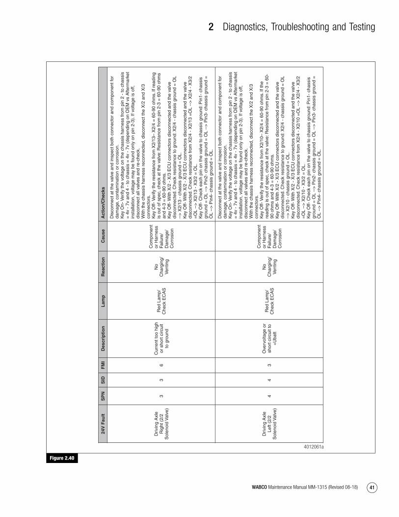
2 Diagnostics, Troubleshooting and Testing
41WABCO Maintenance Manual MM-1315 (Revised 08-18)
Figure 2.40
Figure 2.40
24V
Fau
ltS
PN
SID
FM
ID
escr
ipti
on
Lam
pR
eact
ion
Cau
seA
ctio
n/C
hec
ks
Driv
ing
Axl
e R
ight
(2/
2 S
olen
oid
Val
ve)
33
6C
urre
nt to
o hi
gh
or s
hort
circ
uit
to g
roun
d
Red
Lam
p/
Che
ck E
CA
S
No
Cha
rgin
g/
Ven
ting
Com
pone
nt
or H
arne
ss
Failu
re/
Dam
age/
C
orro
sion
Dis
conn
ect a
t the
val
ve a
nd in
spec
t bot
h co
nnec
tor
and
com
pone
nt fo
r da
mag
e, c
onta
min
atio
n or
cor
rosi
on.
Key
On-
Ver
ify th
e vo
ltage
on
the
chas
sis
harn
ess
from
pin
2 -
to c
hass
is
= 4
v -
7v a
nd 4
- to
cha
ssis
= 4
v -
7v (
depe
ndin
g on
OE
M v
s A
fterm
arke
t in
stal
latio
n, v
olta
ge m
ay b
e fo
und
only
on
pin
2-3)
. If v
olta
ge is
off,
di
scon
nect
all
valv
es a
nd r
e-ch
eck.
W
ith th
e ch
assi
s ha
rnes
s re
conn
ecte
d, d
isco
nnec
t the
X/2
and
X/3
co
nnec
tors
. K
ey O
ff- V
erify
the
resi
stan
ce fr
om X
2/13
– X
2/4
= 6
0-90
ohm
s. If
rea
ding
is
out
of s
pec,
che
ck a
t the
val
ve: R
esis
tanc
e fr
om p
in 2
-3 =
60-
90 o
hms
and
4-3
= 6
0-90
ohm
s.
Key
Off-
With
X/2
- X
/3 E
CU
con
nect
ors
disc
onne
cted
and
the
valv
e di
scon
nect
ed. C
heck
res
ista
nce
to g
roun
d: X
2/4
- ch
assi
s gr
ound
= O
L --
> X
2/13
- c
hass
is g
roun
d =
OL.
K
ey O
ff- W
ith X
/2 -
X/3
EC
U c
onne
ctor
s di
scon
nect
ed a
nd th
e va
lve
disc
onne
cted
. Che
ck r
esis
tanc
e fr
om X
2/4
- X
2/13
=O
L --
> X
2/4
- X
3/2
=O
L --
> X
2/13
- X
3/2
= O
L.
Key
Off-
Che
ck e
ach
pin
on th
e va
lve
to c
hass
is g
roun
d: P
in1-
cha
ssis
gr
ound
= O
L --
> P
in2-
cha
ssis
gro
und
= O
L --
> P
in3-
cha
ssis
gro
und
=
OL
-->
Pin
4- c
hass
is g
roun
d =
OL.
Driv
ing
Axl
e Le
ft (2
/2
Sol
enoi
d V
alve
)4
43
Ove
rvol
tage
or
shor
t circ
uit t
o +
Uba
tt
Red
Lam
p/
Che
ck E
CA
S
No
Cha
rgin
g/
Ven
ting
Com
pone
nt
or H
arne
ss
Failu
re/
Dam
age/
C
orro
sion
Dis
conn
ect a
t the
val
ve a
nd in
spec
t bot
h co
nnec
tor
and
com
pone
nt fo
r da
mag
e, c
onta
min
atio
n or
cor
rosi
on.
Key
On-
Ver
ify th
e vo
ltage
on
the
chas
sis
harn
ess
from
pin
2 -
to c
hass
is
= 4
v -
7v a
nd 4
- to
cha
ssis
= 4
v -
7v (
depe
ndin
g on
OE
M v
s A
fterm
arke
t in
stal
latio
n, v
olta
ge m
ay b
e fo
und
only
on
pin
2-3)
. If v
olta
ge is
off,
di
scon
nect
all
valv
es a
nd r
e-ch
eck.
W
ith th
e ch
assi
s ha
rnes
s re
conn
ecte
d, d
isco
nnec
t the
X/2
and
X/3
co
nnec
tors
. K
ey O
ff- V
erify
the
resi
stan
ce fr
om X
2/10
– X
2/4
= 6
0-90
ohm
s. If
the
read
ing
is o
ut o
f spe
c, c
heck
at t
he v
alve
: Res
ista
nce
from
pin
2-3
= 6
0-90
ohm
s an
d 4-
3 =
60-
90 o
hms.
K
ey O
ff- W
ith X
/2 -
X/3
EC
U c
onne
ctor
s di
scon
nect
ed a
nd th
e va
lve
disc
onne
cted
. Che
ck r
esis
tanc
e to
gro
und:
X2/
4 -
chas
sis
grou
nd =
OL
-->
X2/
10 -
cha
ssis
gro
und
= O
L.
Key
Off-
With
X/2
- X
/3 E
CU
con
nect
ors
disc
onne
cted
and
the
valv
e di
scon
nect
ed. C
heck
res
ista
nce
from
X2/
4 -
X2/
10 =
OL
-->
X2/
4 -
X3/
2 =
OL
-->
X2/
10 -
X3/
2 =
OL.
K
ey O
ff- C
heck
eac
h pi
n on
the
valv
e to
cha
ssis
gro
und:
Pin
1- c
hass
is
grou
nd =
OL
-->
Pin
2- c
hass
is g
roun
d =
OL
-->
Pin
3- c
hass
is g
roun
d =
O
L --
> P
in4-
cha
ssis
gro
und
= O
L.
4012061a
mm1315.bk.fm Page 41 Tuesday, July 9, 2019 7:23 PM

2 Diagnostics, Troubleshooting and Testing
42 WABCO Maintenance Manual MM-1315 (Revised 08-18)
Figure 2.41
Figure 2.41
24V
Fau
ltS
PN
SID
FM
ID
escr
ipti
on
Lam
pR
eact
ion
Cau
seA
ctio
n/C
hec
ks
Driv
ing
Axl
e Le
ft (2
/2
Sol
enoi
d V
alve
)4
45
Low
cur
rent
or
open
Red
Lam
p/
Che
ck E
CA
S
No
Cha
rgin
g/
Ven
ting
Com
pone
nt
or H
arne
ss
Failu
re/
Dam
age/
C
orro
sion
Dis
conn
ect a
t the
val
ve a
nd in
spec
t bot
h co
nnec
tor
and
com
pone
nt fo
r da
mag
e, c
onta
min
atio
n or
cor
rosi
on.
Key
On-
Ver
ify v
olta
ge o
n th
e ch
assi
s ha
rnes
s fr
om p
in 2
- to
cha
ssis
=
4v -
7v
and
4 -
to c
hass
is =
4v
- 7v
( d
epen
ding
on
OE
M v
s A
fterm
arke
t in
stal
latio
n, v
olta
ge m
ay b
e fo
und
only
on
pin
2-3)
. If v
olta
ge is
off,
di
scon
nect
all
valv
es a
nd r
e-ch
eck.
W
ith th
e ch
assi
s ha
rnes
s re
conn
ecte
d, d
isco
nnec
t the
X/2
and
X/3
co
nnec
tors
. K
ey O
ff- V
erify
the
resi
stan
ce fr
om X
2/10
– X
2/4
= 6
0-90
ohm
s. If
the
read
ing
is o
ut o
f spe
c, c
heck
at t
he v
alve
: Res
ista
nce
from
pin
2-3
= 6
0-90
ohm
s an
d 4-
3 =
60-
90 o
hms.
K
ey O
ff- W
ith X
/2 -
X/3
EC
U c
onne
ctor
s di
scon
nect
ed a
nd th
e va
lve
disc
onne
cted
. Che
ck r
esis
tanc
e to
gro
und:
X2/
4 -
chas
sis
grou
nd =
OL
-->
X2/
10 -
cha
ssis
gro
und
= O
L.
Key
Off-
With
X/2
- X
/3 E
CU
con
nect
ors
disc
onne
cted
and
the
valv
e di
scon
nect
ed. C
heck
res
ista
nce
from
X2/
4 -
X2/
10 =
OL
-->
X2/
4 -
X3/
2 =
OL
-->
X2/
10 -
X3/
2 =
OL.
K
ey O
ff -
Che
ck e
ach
pin
on th
e va
lve
to c
hass
is g
roun
d: P
in1-
cha
ssis
gr
ound
= O
L --
> P
in2-
cha
ssis
gro
und
= O
L --
> P
in3-
cha
ssis
gro
und
=
OL
-->
Pin
4- c
hass
is g
roun
d =
OL.
Driv
ing
Axl
e Le
ft (2
/2
Sol
enoi
d V
alve
)4
46
Cur
rent
too
high
or
sho
rt c
ircui
t to
gro
und
Red
Lam
p/
Che
ck E
CA
S
No
Cha
rgin
g/
Ven
ting
Com
pone
nt
or H
arne
ss
Failu
re/
Dam
age/
C
orro
sion
Dis
conn
ect a
t the
val
ve a
nd in
spec
t bot
h co
nnec
tor
and
com
pone
nt fo
r da
mag
e, c
onta
min
atio
n or
cor
rosi
on.
Key
On-
Ver
ify th
e vo
ltage
on
the
chas
sis
harn
ess
from
pin
2 -
to c
hass
is
= 4
v -
7v a
nd 4
- to
cha
ssis
= 4
v -
7v (
depe
ndin
g on
OE
M v
s A
fterm
arke
t in
stal
latio
n, v
olta
ge m
ay b
e fo
und
only
on
pin
2-3)
. If t
he v
olta
ge is
off,
di
scon
nect
all
valv
es a
nd r
e-ch
eck.
W
ith th
e ch
assi
s ha
rnes
s re
conn
ecte
d, d
isco
nnec
t the
X/2
and
X/3
co
nnec
tors
. K
ey O
ff- V
erify
the
resi
stan
ce fr
om X
2/10
– X
2/4
= 6
0-90
ohm
s. If
rea
ding
is
out
of s
pec,
che
ck a
t the
val
ve: R
esis
tanc
e fr
om p
in 2
-3 =
60-
90 o
hms
and
4-3
= 6
0-90
ohm
s.
Key
Off-
With
X/2
- X
/3 E
CU
con
nect
ors
disc
onne
cted
and
the
valv
e di
scon
nect
ed. C
heck
res
ista
nce
to g
roun
d: X
2/4
- ch
assi
s gr
ound
= O
L --
> X
2/10
- c
hass
is g
roun
d =
OL.
K
ey O
ff- W
ith X
/2 -
X/3
EC
U c
onne
ctor
s di
scon
nect
ed a
nd th
e va
lve
disc
onne
cted
. Che
ck r
esis
tanc
e fr
om X
2/4
- X
2/10
=O
L --
> X
2/4
- X
3/2
=O
L --
> X
2/10
- X
3/2
= O
L.
Key
Off-
Che
ck e
ach
pin
on th
e va
lve
to c
hass
is g
roun
d: P
in1-
cha
ssis
gr
ound
= O
L --
> P
in2-
cha
ssis
gro
und
= O
L --
> P
in3-
cha
ssis
gro
und
=
OL
-->
Pin
4- c
hass
is g
roun
d =
OL.
4012062a
mm1315.bk.fm Page 42 Tuesday, July 9, 2019 7:23 PM

2 Diagnostics, Troubleshooting and Testing
43WABCO Maintenance Manual MM-1315 (Revised 08-18)
Figure 2.42
Figure 2.42
24V
Fau
ltS
PN
SID
FM
ID
escr
ipti
on
Lam
pR
eact
ion
Cau
seA
ctio
n/C
hec
ks
Trai
ling
Axl
e R
ight
(2/
2 S
olen
oid
Val
ve)
55
3O
verv
olta
ge o
r sh
ort c
ircui
t to
+U
batt
Red
Lam
p/
Che
ck E
CA
S
No
Cha
rgin
g/
Ven
ting
Com
pone
nt
or H
arne
ss
Failu
re/
Dam
age/
C
orro
sion
Dis
conn
ect a
t the
val
ve a
nd in
spec
t bot
h co
nnec
tor
and
com
pone
nt fo
r da
mag
e, c
onta
min
atio
n or
cor
rosi
on.
Key
On-
Ver
ify v
olta
ge o
n th
e ch
assi
s ha
rnes
s fr
om p
in 2
- to
cha
ssis
=
4v -
7v
and
4 -
to c
hass
is =
4v
- 7v
(de
pend
ing
on O
EM
vs
Afte
rmar
ket
inst
alla
tion,
vol
tage
may
be
foun
d on
ly o
n pi
n 2-
3). I
f the
vol
tage
is o
ff,
disc
onne
ct a
ll va
lves
and
re-
chec
k.
With
the
chas
sis
harn
ess
reco
nnec
ted,
dis
conn
ect t
he X
/2 a
nd X
/3
conn
ecto
rs.
Key
Off-
Ver
ify th
e re
sist
ance
from
X3/
6 –
X2/
4 =
60-
90 o
hms.
If th
e re
adin
g is
out
of s
pec,
che
ck a
t the
val
ve: R
esis
tanc
e fr
om p
in 2
-3 =
60-
90 o
hms
and
4-3
= 6
0-90
ohm
s.
Key
Off-
With
X/2
- X
/3 E
CU
con
nect
ors
disc
onne
cted
and
the
valv
e di
scon
nect
ed. C
heck
res
ista
nce
to g
roun
d: X
2/4
- ch
assi
s gr
ound
= O
L --
> X
3/6
- ch
assi
s gr
ound
= O
L.
Key
Off-
With
X/2
- X
/3 E
CU
con
nect
ors
disc
onne
cted
and
the
valv
e di
scon
nect
ed. C
heck
res
ista
nce
from
X2/
4 -
X3/
6 =
OL
-->
X2/
4 -
X3/
2 =
OL
-->
X3/
6 -
X3/
2 =
OL.
K
ey O
ff- C
heck
eac
h pi
n on
the
valv
e to
cha
ssis
gro
und:
Pin
1- c
hass
is
grou
nd =
OL
-->
Pin
2- c
hass
is g
roun
d =
OL
-->
Pin
3- c
hass
is g
roun
d =
O
L --
> P
in4-
cha
ssis
gro
und
= O
L.
Trai
ling
Axl
e R
ight
(2/
2 S
olen
oid
Val
ve)
55
5Lo
w c
urre
nt o
r op
enR
ed L
amp/
C
heck
EC
AS
No
Cha
rgin
g/
Ven
ting
Com
pone
nt
or H
arne
ss
Failu
re/
Dam
age/
C
orro
sion
Dis
conn
ect a
t the
val
ve a
nd in
spec
t bot
h co
nnec
tor
and
com
pone
nt fo
r da
mag
e, c
onta
min
atio
n or
cor
rosi
on.
Key
On-
Ver
ify th
e vo
ltage
on
the
chas
sis
harn
ess
from
pin
2 -
to c
hass
is
= 4
v -
7v a
nd 4
- to
cha
ssis
= 4
v -
7v (
depe
ndin
g on
OE
M v
s A
fterm
arke
t in
stal
latio
n, v
olta
ge m
ay b
e fo
und
only
on
pin
2-3)
. If t
he v
olta
ge is
off,
di
scon
nect
all
valv
es a
nd r
e-ch
eck.
W
ith th
e ch
assi
s ha
rnes
s re
conn
ecte
d, d
isco
nnec
t the
X/2
and
X/3
co
nnec
tors
. K
ey O
ff- V
erify
the
resi
stan
ce fr
om X
3/6
– X
2/4
= 6
0-90
ohm
s. If
rea
ding
is
out
of s
pec,
che
ck a
t the
val
ve: R
esis
tanc
e fr
om p
in 2
-3 =
60-
90 o
hms
and
4-3
= 6
0-90
ohm
s.
Key
Off-
With
X/2
- X
/3 E
CU
con
nect
ors
disc
onne
cted
and
the
valv
e di
scon
nect
ed. C
heck
res
ista
nce
to g
roun
d: X
2/4
- ch
assi
s gr
ound
= O
L --
> X
3/6
- ch
assi
s gr
ound
= O
L.
Key
Off-
With
X/2
- X
/3 E
CU
con
nect
ors
disc
onne
cted
and
the
valv
e di
scon
nect
ed. C
heck
res
ista
nce
from
X2/
4 -
X3/
6 =
OL
-->
X2/
4 -
X3/
2 =
OL
-->
X3/
6 -
X3/
2 =
OL.
K
ey O
ff- C
heck
eac
h pi
n on
the
valv
e to
cha
ssis
gro
und:
Pin
1- c
hass
is
grou
nd =
OL
-->
Pin
2- c
hass
is g
roun
d =
OL
-->
Pin
3- c
hass
is g
roun
d =
O
L --
> P
in4-
cha
ssis
gro
und
= O
L.
4012063a
mm1315.bk.fm Page 43 Tuesday, July 9, 2019 7:23 PM

2 Diagnostics, Troubleshooting and Testing
44 WABCO Maintenance Manual MM-1315 (Revised 08-18)
Figure 2.43
Figure 2.43
24V
Fau
ltS
PN
SID
FM
ID
escr
ipti
on
Lam
pR
eact
ion
Cau
seA
ctio
n/C
hec
ks
Trai
ling
Axl
e R
ight
(2/
2 S
olen
oid
Val
ve)
55
6C
urre
nt to
o hi
gh
or s
hort
circ
uit
to g
roun
d
Red
Lam
p/
Che
ck E
CA
S
No
Cha
rgin
g/
Ven
ting
Com
pone
nt
or H
arne
ss
Failu
re/
Dam
age/
C
orro
sion
Dis
conn
ect a
t the
val
ve a
nd in
spec
t bot
h co
nnec
tor
and
com
pone
nt fo
r da
mag
e, c
onta
min
atio
n or
cor
rosi
on.
Key
On-
Ver
ify th
e vo
ltage
on
the
chas
sis
harn
ess
from
pin
2 -
to c
hass
is
= 4
v -
7v a
nd 4
- to
cha
ssis
= 4
v -
7v (
depe
ndin
g on
OE
M v
s A
fterm
arke
t in
stal
latio
n, v
olta
ge m
ay b
e fo
und
only
on
pin
2-3)
. If v
olta
ge is
off,
di
scon
nect
all
valv
es a
nd r
e-ch
eck.
W
ith th
e ch
assi
s ha
rnes
s re
conn
ecte
d, d
isco
nnec
t the
X/2
and
X/3
co
nnec
tors
. K
ey O
ff- V
erify
the
resi
stan
ce fr
om X
3/6
– X
2/4
= 6
0-90
ohm
s. If
rea
ding
is
out
of s
pec,
che
ck a
t the
val
ve: R
esis
tanc
e fr
om p
in 2
-3 =
60-
90 o
hms
and
4-3
= 6
0-90
ohm
s.
Key
Off-
With
X/2
- X
/3 E
CU
con
nect
ors
disc
onne
cted
and
the
valv
e di
scon
nect
ed. C
heck
res
ista
nce
to g
roun
d: X
2/4
- ch
assi
s gr
ound
= O
L --
> X
3/6
- ch
assi
s gr
ound
= O
L.
Key
Off-
With
X/2
- X
/3 E
CU
con
nect
ors
disc
onne
cted
and
the
valv
e di
scon
nect
ed. C
heck
res
ista
nce
from
X2/
4 -
X3/
6 =
OL
-->
X2/
4 -
X3/
2 =
OL
-->
X3/
6 -
X3/
2 =
OL.
K
ey O
ff- C
heck
eac
h pi
n on
the
valv
e to
cha
ssis
gro
und:
Pin
1- c
hass
is
grou
nd =
OL
-->
Pin
2- c
hass
is g
roun
d =
OL
-->
Pin
3- c
hass
is g
roun
d =
O
L --
> P
in4-
cha
ssis
gro
und
= O
L.
Trai
ling
Axl
e Le
ft (2
/2
Sol
enoi
d V
alve
)6
63
Ove
rvol
tage
or
shor
t circ
uit t
o +
Uba
tt
Red
Lam
p/
Che
ck E
CA
S
No
Cha
rgin
g/
Ven
ting
Com
pone
nt
or H
arne
ss
Failu
re/
Dam
age/
C
orro
sion
Dis
conn
ect a
t the
val
ve a
nd in
spec
t bot
h co
nnec
tor
and
com
pone
nt fo
r da
mag
e, c
onta
min
atio
n or
cor
rosi
on.
Key
On-
Ver
ify th
e vo
ltage
on
the
chas
sis
harn
ess
from
pin
2 -
to c
hass
is
= 4
v -
7v a
nd 4
- to
cha
ssis
= 4
v -
7v (
depe
ndin
g on
OE
M v
s A
fterm
arke
t in
stal
latio
n, v
olta
ge m
ay b
e fo
und
only
on
pin
2-3)
. If t
he v
olta
ge is
off,
di
scon
nect
all
valv
es a
nd r
e-ch
eck.
W
ith th
e ch
assi
s ha
rnes
s re
conn
ecte
d, d
isco
nnec
t the
X/2
and
X/3
co
nnec
tors
. K
ey O
ff- V
erify
the
resi
stan
ce fr
om X
3/1
– X
2/4
= 6
0-90
ohm
s. If
the
read
ing
is o
ut o
f spe
c, c
heck
at t
he v
alve
: Res
ista
nce
from
pin
2-3
= 6
0-90
ohm
s an
d 4-
3 =
60-
90 o
hms.
K
ey O
ff- W
ith X
/2 -
X/3
EC
U c
onne
ctor
s di
scon
nect
ed a
nd th
e va
lve
disc
onne
cted
. Che
ck r
esis
tanc
e to
gro
und:
X2/
4 -
chas
sis
grou
nd =
OL
-->
X3/
1 -
chas
sis
grou
nd =
OL.
K
ey O
ff- W
ith X
/2 -
X/3
EC
U c
onne
ctor
s di
scon
nect
ed a
nd th
e va
lve
disc
onne
cted
. Che
ck r
esis
tanc
e fr
om X
2/4
- X
3/1
=O
L --
> X
2/4
- X
3/2
=O
L --
> X
3/1
- X
3/2
= O
L.
Key
Off-
Che
ck e
ach
pin
on th
e va
lve
to c
hass
is g
roun
d: P
in1-
cha
ssis
gr
ound
= O
L --
> P
in2-
cha
ssis
gro
und
= O
L --
> P
in3-
cha
ssis
gro
und
=
OL
-->
Pin
4- c
hass
is g
roun
d =
OL.
4012064a
mm1315.bk.fm Page 44 Tuesday, July 9, 2019 7:23 PM

2 Diagnostics, Troubleshooting and Testing
45WABCO Maintenance Manual MM-1315 (Revised 08-18)
Figure 2.44
Figure 2.44
24V
Fau
ltS
PN
SID
FM
ID
escr
ipti
on
Lam
pR
eact
ion
Cau
seA
ctio
n/C
hec
ks
Trai
ling
Axl
e Le
ft (2
/2
Sol
enoi
d V
alve
)6
65
Low
cur
rent
or
open
Red
Lam
p/
Che
ck E
CA
S
No
Cha
rgin
g/
Ven
ting
Com
pone
nt
or H
arne
ss
Failu
re/
Dam
age/
C
orro
sion
Dis
conn
ect a
t the
val
ve a
nd in
spec
t bot
h co
nnec
tor
and
com
pone
nt fo
r da
mag
e, c
onta
min
atio
n or
cor
rosi
on.
Key
On-
Ver
ify v
olta
ge o
n th
e ch
assi
s ha
rnes
s fr
om p
in 2
- to
cha
ssis
=
4v -
7v
and
4 -
to c
hass
is =
4v
- 7v
(de
pend
ing
on O
EM
vs
Afte
rmar
ket
inst
alla
tion,
vol
tage
may
be
foun
d on
ly o
n pi
n 2-
3). I
f vol
tage
is o
ff,
disc
onne
ct a
ll va
lves
and
re-
chec
k.
With
the
chas
sis
harn
ess
reco
nnec
ted,
dis
conn
ect t
he X
/2 a
nd X
/3
conn
ecto
rs.
Key
Off-
Ver
ify th
e re
sist
ance
from
X3/
1 –
X2/
4 =
60-
90 o
hms.
If r
eadi
ng
is o
ut o
f spe
c, c
heck
at t
he v
alve
: Res
ista
nce
from
pin
2-3
= 6
0-90
ohm
s an
d 4-
3 =
60-
90 o
hms.
K
ey O
ff- W
ith X
/2 -
X/3
EC
U c
onne
ctor
s di
scon
nect
ed a
nd th
e va
lve
disc
onne
cted
. Che
ck r
esis
tanc
e to
gro
und:
X2/
4 -
chas
sis
grou
nd =
OL
-->
X3/
1 -
chas
sis
grou
nd =
OL.
K
ey O
ff- W
ith X
/2 -
X/3
EC
U c
onne
ctor
s di
scon
nect
ed a
nd th
e va
lve
disc
onne
cted
. Che
ck r
esis
tanc
e fr
om X
2/4
- X
3/1
=O
L --
> X
2/4
- X
3/2
=O
L --
> X
3/1
- X
3/2
= O
L.
Key
Off-
Che
ck e
ach
pin
on th
e va
lve
to c
hass
is g
roun
d: P
in1-
cha
ssis
gr
ound
= O
L --
> P
in2-
cha
ssis
gro
und
= O
L --
> P
in3-
cha
ssis
gro
und
=
OL
-->
Pin
4- c
hass
is g
roun
d =
OL.
Trai
ling
Axl
e Le
ft (2
/2
Sol
enoi
d V
alve
)6
66
Cur
rent
too
high
or
sho
rt c
ircui
t to
gro
und
Red
Lam
p/
Che
ck E
CA
S
No
Cha
rgin
g/
Ven
ting
Com
pone
nt
or H
arne
ss
Failu
re/
Dam
age/
C
orro
sion
Dis
conn
ect a
t the
val
ve a
nd in
spec
t bot
h co
nnec
tor
and
com
pone
nt fo
r da
mag
e, c
onta
min
atio
n or
cor
rosi
on:
Key
On-
Ver
ify th
e vo
ltage
on
the
chas
sis
harn
ess
from
pin
2 -
to c
hass
is
= 4
v -
7v a
nd 4
- to
cha
ssis
= 4
v -
7v (
depe
ndin
g on
OE
M v
s A
fterm
arke
t in
stal
latio
n, v
olta
ge m
ay b
e fo
und
only
on
pin
2-3)
. If t
he v
olta
ge is
off,
di
scon
nect
all
valv
es a
nd r
e-ch
eck.
W
ith th
e ch
assi
s ha
rnes
s re
conn
ecte
d, d
isco
nnec
t the
X/2
and
X/3
co
nnec
tors
. K
ey O
ff- V
erify
the
resi
stan
ce fr
om X
3/1
– X
2/4
= 6
0-90
ohm
s. If
rea
ding
is
out
of s
pec,
che
ck a
t the
val
ve: R
esis
tanc
e fr
om p
in 2
-3 =
60-
90 o
hms
and
4-3
= 6
0-90
ohm
s.
Key
Off-
With
X/2
- X
/3 E
CU
con
nect
ors
disc
onne
cted
and
the
valv
e di
scon
nect
ed. C
heck
res
ista
nce
to g
roun
d: X
2/4
- ch
assi
s gr
ound
= O
L --
> X
3/1
- ch
assi
s gr
ound
= O
L.
Key
Off-
With
X/2
- X
/3 E
CU
con
nect
ors
disc
onne
cted
and
the
valv
e di
scon
nect
ed. C
heck
res
ista
nce
from
X2/
4 -
X3/
1 =
OL
-->
X2/
4 -
X3/
2 =
OL
-->
X3/
1 -
X3/
2 =
OL.
K
ey O
ff- C
heck
eac
h pi
n on
the
valv
e to
cha
ssis
gro
und:
Pin
1- c
hass
is
grou
nd =
OL
-->
Pin
2- c
hass
is g
roun
d =
OL
-->
Pin
3- c
hass
is g
roun
d =
O
L --
> P
in4-
cha
ssis
gro
und
= O
L.
4012065a
mm1315.bk.fm Page 45 Tuesday, July 9, 2019 7:23 PM
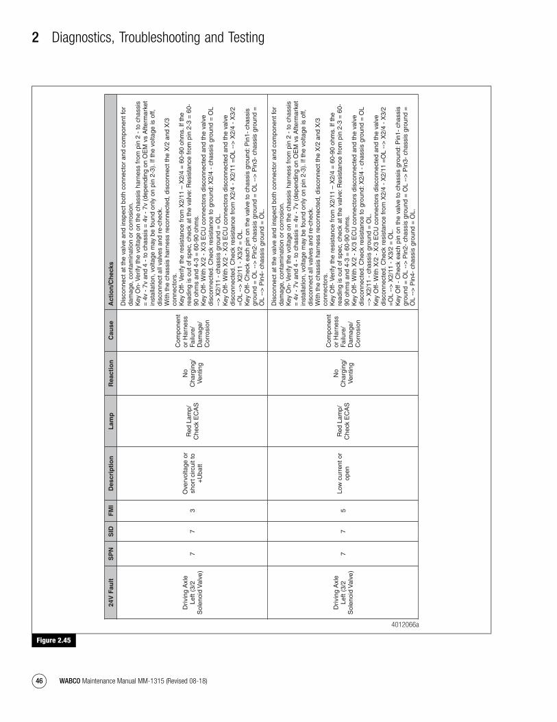
2 Diagnostics, Troubleshooting and Testing
46 WABCO Maintenance Manual MM-1315 (Revised 08-18)
Figure 2.45
Figure 2.45
24V
Fau
ltS
PN
SID
FM
ID
escr
ipti
on
Lam
pR
eact
ion
Cau
seA
ctio
n/C
hec
ks
Driv
ing
Axl
e Le
ft (3
/2
Sol
enoi
d V
alve
)7
73
Ove
rvol
tage
or
shor
t circ
uit t
o +
Uba
tt
Red
Lam
p/
Che
ck E
CA
S
No
Cha
rgin
g/
Ven
ting
Com
pone
nt
or H
arne
ss
Failu
re/
Dam
age/
C
orro
sion
Dis
conn
ect a
t the
val
ve a
nd in
spec
t bot
h co
nnec
tor
and
com
pone
nt fo
r da
mag
e, c
onta
min
atio
n or
cor
rosi
on.
Key
On-
Ver
ify th
e vo
ltage
on
the
chas
sis
harn
ess
from
pin
2 -
to c
hass
is
= 4
v -
7v a
nd 4
- to
cha
ssis
= 4
v -
7v (
depe
ndin
g on
OE
M v
s A
fterm
arke
t in
stal
latio
n, v
olta
ge m
ay b
e fo
und
only
on
pin
2-3)
. If t
he v
olta
ge is
off,
di
scon
nect
all
valv
es a
nd r
e-ch
eck.
W
ith th
e ch
assi
s ha
rnes
s re
conn
ecte
d, d
isco
nnec
t the
X/2
and
X/3
co
nnec
tors
. K
ey O
ff- V
erify
the
resi
stan
ce fr
om X
2/11
– X
2/4
= 6
0-90
ohm
s. If
the
read
ing
is o
ut o
f spe
c, c
heck
at t
he v
alve
: Res
ista
nce
from
pin
2-3
= 6
0-90
ohm
s an
d 4-
3 =
60-
90 o
hms.
K
ey O
ff- W
ith X
/2 -
X/3
EC
U c
onne
ctor
s di
scon
nect
ed a
nd th
e va
lve
disc
onne
cted
. Che
ck r
esis
tanc
e to
gro
und:
X2/
4 -
chas
sis
grou
nd =
OL
-->
X2/
11 -
cha
ssis
gro
und
= O
L.
Key
Off-
With
X/2
- X
/3 E
CU
con
nect
ors
disc
onne
cted
and
the
valv
e di
scon
nect
ed. C
heck
res
ista
nce
from
X2/
4 -
X2/
11 =
OL
-->
X2/
4 -
X3/
2 =
OL
-->
X2/
11 -
X3/
2 =
OL.
K
ey O
ff- C
heck
eac
h pi
n on
the
valv
e to
cha
ssis
gro
und:
Pin
1- c
hass
is
grou
nd =
OL
-->
Pin
2- c
hass
is g
roun
d =
OL
-->
Pin
3- c
hass
is g
roun
d =
O
L --
> P
in4-
cha
ssis
gro
und
= O
L.
Driv
ing
Axl
e Le
ft (3
/2
Sol
enoi
d V
alve
)7
75
Low
cur
rent
or
open
Red
Lam
p/
Che
ck E
CA
S
No
Cha
rgin
g/
Ven
ting
Com
pone
nt
or H
arne
ss
Failu
re/
Dam
age/
C
orro
sion
Dis
conn
ect a
t the
val
ve a
nd in
spec
t bot
h co
nnec
tor
and
com
pone
nt fo
r da
mag
e, c
onta
min
atio
n or
cor
rosi
on.
Key
On-
Ver
ify th
e vo
ltage
on
the
chas
sis
harn
ess
from
pin
2 -
to c
hass
is
= 4
v -
7v a
nd 4
- to
cha
ssis
= 4
v -
7v (
depe
ndin
g on
OE
M v
s A
fterm
arke
t in
stal
latio
n, v
olta
ge m
ay b
e fo
und
only
on
pin
2-3)
. If t
he v
olta
ge is
off,
di
scon
nect
all
valv
es a
nd r
e-ch
eck.
W
ith th
e ch
assi
s ha
rnes
s re
conn
ecte
d, d
isco
nnec
t the
X/2
and
X/3
co
nnec
tors
. K
ey O
ff- V
erify
the
resi
stan
ce fr
om X
2/11
– X
2/4
= 6
0-90
ohm
s. If
the
read
ing
is o
ut o
f spe
c, c
heck
at t
he v
alve
: Res
ista
nce
from
pin
2-3
= 6
0-90
ohm
s an
d 4-
3 =
60-
90 o
hms.
K
ey O
ff- W
ith X
/2 -
X/3
EC
U c
onne
ctor
s di
scon
nect
ed a
nd th
e va
lve
disc
onne
cted
. Che
ck r
esis
tanc
e to
gro
und:
X2/
4 -
chas
sis
grou
nd =
OL
-->
X2/
11 -
cha
ssis
gro
und
= O
L.
Key
Off-
With
X/2
- X
/3 E
CU
con
nect
ors
disc
onne
cted
and
the
valv
e di
scon
nect
ed. C
heck
res
ista
nce
from
X2/
4 -
X2/
11 =
OL
-->
X2/
4 -
X3/
2 =
OL
-->
X2/
11 -
X3/
2 =
OL.
K
ey O
ff -
Che
ck e
ach
pin
on th
e va
lve
to c
hass
is g
roun
d: P
in1-
cha
ssis
gr
ound
= O
L --
> P
in2-
cha
ssis
gro
und
= O
L --
> P
in3-
cha
ssis
gro
und
=
OL
-->
Pin
4- c
hass
is g
roun
d =
OL.
4012066a
mm1315.bk.fm Page 46 Tuesday, July 9, 2019 7:23 PM

2 Diagnostics, Troubleshooting and Testing
47WABCO Maintenance Manual MM-1315 (Revised 08-18)
Figure 2.46
Figure 2.46
24V
Fau
ltS
PN
SID
FM
ID
escr
ipti
on
Lam
pR
eact
ion
Cau
seA
ctio
n/C
hec
ks
Driv
ing
Axl
e Le
ft (3
/2
Sol
enoi
d V
alve
)7
76
Cur
rent
too
high
or
sho
rt c
ircui
t to
gro
und
Red
Lam
p/
Che
ck E
CA
S
No
Cha
rgin
g/
Ven
ting
Com
pone
nt
or H
arne
ss
Failu
re/
Dam
age/
C
orro
sion
Dis
conn
ect a
t the
val
ve a
nd in
spec
t bot
h co
nnec
tor
and
com
pone
nt fo
r da
mag
e, c
onta
min
atio
n or
cor
rosi
on.
Key
On-
Ver
ify th
e vo
ltage
on
the
chas
sis
harn
ess
from
pin
2 -
to c
hass
is
= 4
v -
7v a
nd 4
- to
cha
ssis
= 4
v -
7v (
depe
ndin
g on
OE
M v
s A
fterm
arke
t in
stal
latio
n, v
olta
ge m
ay b
e fo
und
only
on
pin
2-3)
. If v
olta
ge is
off,
di
scon
nect
all
valv
es a
nd r
e-ch
eck.
W
ith th
e ch
assi
s ha
rnes
s re
conn
ecte
d, d
isco
nnec
t the
X/2
and
X/3
co
nnec
tors
. K
ey O
ff - V
erify
the
resi
stan
ce fr
om X
2/11
– X
2/4
= 6
0-90
ohm
s. If
the
read
ing
is o
ut o
f spe
c, c
heck
at t
he v
alve
: Res
ista
nce
from
pin
2-3
= 6
0-90
ohm
s an
d 4-
3 =
60-
90 o
hms.
K
ey O
ff- W
ith X
/2 -
X/3
EC
U c
onne
ctor
s di
scon
nect
ed a
nd th
e va
lve
disc
onne
cted
. Che
ck r
esis
tanc
e to
gro
und:
X2/
4 -
chas
sis
grou
nd =
OL
-->
X2/
11 -
cha
ssis
gro
und
= O
L.
Key
Off-
With
X/2
- X
/3 E
CU
con
nect
ors
disc
onne
cted
and
the
valv
e di
scon
nect
ed. C
heck
res
ista
nce
from
X2/
4 -
X2/
11 =
OL
-->
X2/
4 -
X3/
2 =
OL
-->
X2/
11 -
X3/
2 =
OL.
K
ey O
ff- C
heck
eac
h pi
n on
the
valv
e to
cha
ssis
gro
und:
Pin
1- c
hass
is
grou
nd =
OL
-->
Pin
2- c
hass
is g
roun
d =
OL
-->
Pin
3- c
hass
is g
roun
d =
O
L --
> P
in4-
cha
ssis
gro
und
= O
L.
Lifti
ng/T
raili
ng
Axl
e (3
/3
Sol
enoi
d V
alve
)8
83
Ove
rvol
tage
or
shor
t circ
uit t
o +
Uba
tt
Red
Lam
p/
Che
ck E
CA
S
No
Cha
rgin
g/
Ven
ting
Com
pone
nt
or H
arne
ss
Failu
re/
Dam
age/
C
orro
sion
Dis
conn
ect a
t the
val
ve a
nd in
spec
t bot
h co
nnec
tor
and
com
pone
nt fo
r da
mag
e, c
onta
min
atio
n or
cor
rosi
on.
Key
On-
Ver
ify th
e vo
ltage
on
the
chas
sis
harn
ess
from
pin
2 -
to c
hass
is
= 4
v -
7v a
nd 4
- to
cha
ssis
= 4
v -
7v (
depe
ndin
g on
OE
M v
s A
fterm
arke
t in
stal
latio
n, v
olta
ge m
ay b
e fo
und
only
on
pin
2-3)
. If t
he v
olta
ge is
off,
di
scon
nect
all
valv
es a
nd r
e-ch
eck.
W
ith th
e ch
assi
s ha
rnes
s re
conn
ecte
d, d
isco
nnec
t the
X/2
and
X/3
co
nnec
tors
. K
ey O
ff- V
erify
the
resi
stan
ce fr
om X
2/14
– X
2/4
= 6
0-90
ohm
s. If
rea
ding
is
out
of s
pec,
che
ck a
t the
val
ve: R
esis
tanc
e fr
om p
in 2
-3 =
60-
90 o
hms
and
4-3
= 6
0-90
ohm
s.
Key
Off-
With
X/2
- X
/3 E
CU
con
nect
ors
disc
onne
cted
and
the
valv
e di
scon
nect
ed. C
heck
res
ista
nce
to g
roun
d: X
2/4
- ch
assi
s gr
ound
= O
L --
> X
2/14
- c
hass
is g
roun
d =
OL.
K
ey O
ff- W
ith X
/2 -
X/3
EC
U c
onne
ctor
s di
scon
nect
ed a
nd th
e va
lve
disc
onne
cted
. Che
ck r
esis
tanc
e fr
om X
2/4
- X
2/14
=O
L --
> X
2/4
- X
3/2
=O
L --
> X
2/14
- X
3/2
= O
L.
Key
Off-
Che
ck e
ach
pin
on th
e va
lve
to c
hass
is g
roun
d: P
in1-
cha
ssis
gr
ound
= O
L --
> P
in2-
cha
ssis
gro
und
= O
L --
> P
in3-
cha
ssis
gro
und
=
OL
-->
Pin
4- c
hass
is g
roun
d =
OL.
4012067a
mm1315.bk.fm Page 47 Tuesday, July 9, 2019 7:23 PM

2 Diagnostics, Troubleshooting and Testing
48 WABCO Maintenance Manual MM-1315 (Revised 08-18)
Figure 2.47
Figure 2.47
24V
Fau
ltS
PN
SID
FM
ID
escr
ipti
on
Lam
pR
eact
ion
Cau
seA
ctio
n/C
hec
ks
Lifti
ng/T
raili
ng
Axl
e (3
/3
Sol
enoi
d V
alve
)8
85
Low
cur
rent
or
open
Red
Lam
p/
Che
ck E
CA
S
No
Cha
rgin
g/
Ven
ting
Com
pone
nt
or H
arne
ss
Failu
re/
Dam
age/
C
orro
sion
Dis
conn
ect a
t the
val
ve a
nd in
spec
t bot
h co
nnec
tor
and
com
pone
nt fo
r da
mag
e, c
onta
min
atio
n or
cor
rosi
on.
Key
On-
Ver
ify th
e vo
ltage
on
the
chas
sis
harn
ess
from
pin
2 -
to c
hass
is
= 4
v -
7v a
nd 4
- to
cha
ssis
= 4
v -
7v (
depe
ndin
g on
OE
M v
s A
fterm
arke
t in
stal
latio
n, v
olta
ge m
ay b
e fo
und
only
on
pin
2-3)
. If t
he v
olta
ge is
off,
di
scon
nect
all
valv
es a
nd r
e-ch
eck.
W
ith th
e ch
assi
s ha
rnes
s re
conn
ecte
d, d
isco
nnec
t the
X/2
and
X/3
co
nnec
tors
. K
ey O
ff- V
erify
the
resi
stan
ce fr
om X
2/14
– X
2/4
= 6
0-90
ohm
s. If
the
read
ing
is o
ut o
f spe
c, c
heck
at t
he v
alve
: Res
ista
nce
from
pin
2-3
= 6
0-90
ohm
s an
d 4-
3 =
60-
90 o
hms.
K
ey O
ff- W
ith X
/2 -
X/3
EC
U c
onne
ctor
s di
scon
nect
ed a
nd th
e va
lve
disc
onne
cted
. Che
ck r
esis
tanc
e to
gro
und:
X2/
4 -
chas
sis
grou
nd =
OL
-->
X2/
14 -
cha
ssis
gro
und
= O
L.
Key
Off-
With
X/2
- X
/3 E
CU
con
nect
ors
disc
onne
cted
and
the
valv
e di
scon
nect
ed. C
heck
res
ista
nce
from
X2/
4 -
X2/
14 =
OL
-->
X2/
4 -
X3/
2 =
OL
-->
X2/
14 -
X3/
2 =
OL.
K
ey O
ff- C
heck
eac
h pi
n on
the
valv
e to
cha
ssis
gro
und:
Pin
1- c
hass
is
grou
nd =
OL
-->
Pin
2- c
hass
is g
roun
d =
OL
-->
Pin
3- c
hass
is g
roun
d =
O
L --
> P
in4-
cha
ssis
gro
und
= O
L.
Lifti
ng/T
raili
ng
Axl
e (3
/3
Sol
enoi
d V
alve
)8
86
Cur
rent
too
high
or
sho
rt c
ircui
t to
gro
und
Red
Lam
p/
Che
ck E
CA
S
No
Cha
rgin
g/
Ven
ting
Com
pone
nt
or H
arne
ss
Failu
re/
Dam
age/
C
orro
sion
Dis
conn
ect a
t the
val
ve a
nd in
spec
t bot
h co
nnec
tor
and
com
pone
nt fo
r da
mag
e, c
onta
min
atio
n or
cor
rosi
on.
Key
On-
Ver
ify th
e vo
ltage
on
the
chas
sis
harn
ess
from
pin
2 -
to c
hass
is
= 4
v -
7v a
nd 4
- to
cha
ssis
= 4
v -
7v (
depe
ndin
g on
OE
M v
s A
fterm
arke
t in
stal
latio
n, v
olta
ge m
ay b
e fo
und
only
on
pin
2-3)
. If t
he v
olta
ge is
off,
di
scon
nect
all
valv
es a
nd r
e-ch
eck.
W
ith th
e ch
assi
s ha
rnes
s re
conn
ecte
d, d
isco
nnec
t the
X/2
and
X/3
co
nnec
tors
. K
ey O
ff- V
erify
the
resi
stan
ce fr
om X
2/14
– X
2/4
= 6
0-90
ohm
s. If
the
read
ing
is o
ut o
f spe
c, c
heck
at t
he v
alve
: Res
ista
nce
from
pin
2-3
= 6
0-90
ohm
s an
d 4-
3 =
60-
90 o
hms.
K
ey O
ff- W
ith X
/2 -
X/3
EC
U c
onne
ctor
s di
scon
nect
ed a
nd th
e va
lve
disc
onne
cted
. Che
ck r
esis
tanc
e to
gro
und:
X2/
4 -
chas
sis
grou
nd =
OL
-->
X2/
14 -
cha
ssis
gro
und
= O
L.
Key
Off-
With
X/2
- X
/3 E
CU
con
nect
ors
disc
onne
cted
and
the
valv
e di
scon
nect
ed. C
heck
res
ista
nce
from
X2/
4 -
X2/
14 =
OL
-->
X2/
4 -
X3/
2 =
OL
-->
X2/
14 -
X3/
2 =
OL.
K
ey O
ff- C
heck
eac
h pi
n on
the
valv
e to
cha
ssis
gro
und:
Pin
1- c
hass
is
grou
nd =
OL
-->
Pin
2- c
hass
is g
roun
d =
OL
-->
Pin
3- c
hass
is g
roun
d =
O
L --
> P
in4-
cha
ssis
gro
und
= O
L.
4012068a
mm1315.bk.fm Page 48 Tuesday, July 9, 2019 7:23 PM

2 Diagnostics, Troubleshooting and Testing
49WABCO Maintenance Manual MM-1315 (Revised 08-18)
Figure 2.48
Figure 2.48
24V
Fau
ltS
PN
SID
FM
ID
escr
ipti
on
Lam
pR
eact
ion
Cau
seA
ctio
n/C
hec
ks
Low
er L
iftin
g/Tr
ailin
g A
xle
(3/3
Sol
enoi
d V
alve
)
99
3O
verv
olta
ge o
r sh
ort c
ircui
t to
+U
batt
Red
Lam
p/
Che
ck E
CA
S
No
Cha
rgin
g/
Ven
ting
Com
pone
nt
or H
arne
ss
Failu
re/
Dam
age/
C
orro
sion
Dis
conn
ect a
t the
val
ve a
nd in
spec
t bot
h co
nnec
tor
and
com
pone
nt fo
r da
mag
e, c
onta
min
atio
n or
cor
rosi
on.
Key
On-
Ver
ify th
e vo
ltage
on
the
chas
sis
harn
ess
from
pin
2 -
to c
hass
is
= 4
v -
7v a
nd 4
- to
cha
ssis
= 4
v -
7v (
depe
ndin
g on
OE
M v
s A
fterm
arke
t in
stal
latio
n, v
olta
ge m
ay b
e fo
und
only
on
pin
2-3)
. If t
he v
olta
ge is
off,
di
scon
nect
all
valv
es a
nd r
e-ch
eck.
W
ith th
e ch
assi
s ha
rnes
s re
conn
ecte
d, d
isco
nnec
t the
X/2
and
X/3
co
nnec
tors
. K
ey O
ff- V
erify
the
resi
stan
ce fr
om X
2/14
– X
2/4
= 6
0-90
ohm
s. If
the
read
ing
is o
ut o
f spe
c, c
heck
at t
he v
alve
: Res
ista
nce
from
pin
2-3
= 6
0-90
ohm
s an
d 4-
3 =
60-
90 o
hms.
K
ey O
ff- W
ith X
/2 -
X/3
EC
U c
onne
ctor
s di
scon
nect
ed a
nd th
e va
lve
disc
onne
cted
. Che
ck r
esis
tanc
e to
gro
und:
X2/
4 -
chas
sis
grou
nd =
OL
-->
X2/
14 -
cha
ssis
gro
und
= O
L.
Key
Off-
With
X/2
- X
/3 E
CU
con
nect
ors
disc
onne
cted
and
the
valv
e di
scon
nect
ed. C
heck
res
ista
nce
from
X2/
4 -
X2/
14 =
OL
-->
X2/
4 -
X3/
2 =
OL
-->
X2/
14 -
X3/
2 =
OL.
K
ey O
ff- C
heck
eac
h pi
n on
the
valv
e to
cha
ssis
gro
und:
Pin
1- c
hass
is
grou
nd =
OL
-->
Pin
2- c
hass
is g
roun
d =
OL
-->
Pin
3- c
hass
is g
roun
d =
O
L --
> P
in4-
cha
ssis
gro
und
= O
L.
Low
er L
iftin
g/Tr
ailin
g A
xle
(3/3
Sol
enoi
d V
alve
)
99
5Lo
w c
urre
nt o
r op
enR
ed L
amp/
C
heck
EC
AS
No
Cha
rgin
g/
Ven
ting
Com
pone
nt
or H
arne
ss
Failu
re/
Dam
age/
C
orro
sion
Dis
conn
ect a
t the
val
ve a
nd in
spec
t bot
h co
nnec
tor
and
com
pone
nt fo
r da
mag
e, c
onta
min
atio
n or
cor
rosi
on.
Key
On-
Ver
ify th
e vo
ltage
on
the
chas
sis
harn
ess
from
pin
2 -
to c
hass
is
= 4
v -
7v a
nd 4
- to
cha
ssis
= 4
v -
7v (
depe
ndin
g on
OE
M v
s A
fterm
arke
t in
stal
latio
n, v
olta
ge m
ay b
e fo
und
only
on
pin
2-3)
. If t
he v
olta
ge is
off,
di
scon
nect
all
valv
es a
nd r
e-ch
eck.
W
ith th
e ch
assi
s ha
rnes
s re
conn
ecte
d, d
isco
nnec
t the
X/2
and
X/3
co
nnec
tors
. K
ey O
ff- V
erify
the
resi
stan
ce fr
om X
2/14
– X
2/4
= 6
0-90
ohm
s. If
rea
ding
is
out
of s
pec,
che
ck a
t the
val
ve: R
esis
tanc
e fr
om p
in 2
-3 =
60-
90 o
hms
and
4-3
= 6
0-90
ohm
s.
Key
Off-
With
X/2
- X
/3 E
CU
con
nect
ors
disc
onne
cted
and
the
valv
e di
scon
nect
ed. C
heck
res
ista
nce
to g
roun
d: X
2/4
- ch
assi
s gr
ound
= O
L --
> X
2/14
- c
hass
is g
roun
d =
OL.
K
ey O
ff- W
ith X
/2 -
X/3
EC
U c
onne
ctor
s di
scon
nect
ed a
nd th
e va
lve
disc
onne
cted
. Che
ck r
esis
tanc
e fr
om X
2/4
- X
2/14
=O
L --
> X
2/4
- X
3/2
=O
L --
> X
2/14
- X
3/2
= O
L.
Key
Off-
Che
ck e
ach
pin
on th
e va
lve
to c
hass
is g
roun
d: P
in1-
cha
ssis
gr
ound
= O
L --
> P
in2-
cha
ssis
gro
und
= O
L --
> P
in3-
cha
ssis
gro
und
=
OL
-->
Pin
4- c
hass
is g
roun
d =
OL.
4012069a
mm1315.bk.fm Page 49 Tuesday, July 9, 2019 7:23 PM
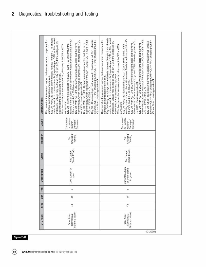
2 Diagnostics, Troubleshooting and Testing
50 WABCO Maintenance Manual MM-1315 (Revised 08-18)
Figure 2.49
Figure 2.49
24V
Fau
ltS
PN
SID
FM
ID
escr
ipti
on
Lam
pR
eact
ion
Cau
seA
ctio
n/C
hec
ks
Fron
t Axl
e C
entr
al (
3/2
Sol
enoi
d V
alve
)44
445
Low
cur
rent
or
open
Red
Lam
p/
Che
ck E
CA
S
No
Cha
rgin
g/
Ven
ting
Com
pone
nt
or H
arne
ss
Failu
re/
Dam
age/
C
orro
sion
Dis
conn
ect a
t the
val
ve a
nd in
spec
t bot
h co
nnec
tor
and
com
pone
nt fo
r da
mag
e, c
onta
min
atio
n or
cor
rosi
on.
Key
On-
Ver
ify th
e vo
ltage
on
the
chas
sis
harn
ess
from
pin
2 -
to c
hass
is
= 4
v -
7v a
nd 4
- to
cha
ssis
= 4
v -
7v (
depe
ndin
g on
OE
M v
s A
fterm
arke
t in
stal
latio
n, v
olta
ge m
ay b
e fo
und
only
on
pin
2-3)
. If t
he v
olta
ge is
off,
di
scon
nect
the
all v
alve
s an
d re
-che
ck.
With
the
chas
sis
harn
ess
reco
nnec
ted,
dis
conn
ect t
he X
/2 a
nd X
/3
conn
ecto
rs.
Key
Off
- Ver
ify th
e re
sist
ance
from
X3/
2– X
2/4
= 6
0-90
ohm
s. If
the
read
ing
is o
ut o
f spe
c, c
heck
at t
he v
alve
: Res
ista
nce
from
pin
2-3
= 6
0-90
ohm
s an
d 4-
3 =
60-
90 o
hms.
K
ey O
ff- W
ith X
/2 -
X/3
EC
U c
onne
ctor
s di
scon
nect
ed a
nd th
e va
lve
disc
onne
cted
. Che
ck r
esis
tanc
e to
gro
und:
X2/
4 -
chas
sis
grou
nd =
OL
-->
X3/
2 -
chas
sis
grou
nd =
OL.
K
ey O
ff- W
ith X
/2 -
X/3
EC
U c
onne
ctor
s di
scon
nect
ed a
nd th
e va
lve
disc
onne
cted
. Che
ck r
esis
tanc
e fr
om X
2/4
- X
2/12
=O
L --
> X
2/4
- X
3/2
=O
L --
> X
2/12
- X
3/2
= O
L.
Key
Off
- C
heck
eac
h pi
n on
the
valv
e to
cha
ssis
gro
und:
Pin
1- c
hass
is
grou
nd =
OL
-->
Pin
2- c
hass
is g
roun
d =
OL
-->
Pin
3- c
hass
is g
roun
d =
O
L --
> P
in4-
cha
ssis
gro
und
= O
L.
Fron
t Axl
e C
entr
al (
3/2
Sol
enoi
d V
alve
)44
446
Cur
rent
too
high
or
sho
rt c
ircui
t to
gro
und
Red
Lam
p/
Che
ck E
CA
S
No
Cha
rgin
g/
Ven
ting
Com
pone
nt
or H
arne
ss
Failu
re/
Dam
age/
C
orro
sion
Dis
conn
ect a
t the
val
ve a
nd in
spec
t bot
h co
nnec
tor
and
com
pone
nt fo
r da
mag
e, c
onta
min
atio
n or
cor
rosi
on.
Key
On-
Ver
ify th
e vo
ltage
on
the
chas
sis
harn
ess
from
pin
2 -
to c
hass
is
= 4
v -
7v a
nd 4
- to
cha
ssis
= 4
v -
7v (
depe
ndin
g on
OE
M v
s A
fterm
arke
t in
stal
latio
n, v
olta
ge m
ay b
e fo
und
only
on
pin
2-3)
. If t
he v
olta
ge is
off,
di
scon
nect
the
all v
alve
s an
d re
-che
ck.
With
the
chas
sis
harn
ess
reco
nnec
ted,
dis
conn
ect t
he X
/2 a
nd X
/3
conn
ecto
rs.
Key
Off-
Ver
ify th
e re
sist
ance
from
X3/
2– X
2/4
= 6
0-90
ohm
s. If
the
read
ing
is o
ut o
f spe
c, c
heck
at t
he v
alve
: Res
ista
nce
from
pin
2-3
= 6
0-90
ohm
s an
d 4-
3 =
60-
90 o
hms.
K
ey O
ff- W
ith X
/2 -
X/3
EC
U c
onne
ctor
s di
scon
nect
ed a
nd th
e va
lve
disc
onne
cted
. Che
ck r
esis
tanc
e to
gro
und:
X2/
4 -
chas
sis
grou
nd =
OL
-->
X3/
2 -
chas
sis
grou
nd =
OL.
K
ey O
ff- W
ith X
/2 -
X/3
EC
U c
onne
ctor
s di
scon
nect
ed a
nd th
e va
lve
disc
onne
cted
. Che
ck r
esis
tanc
e fr
om X
2/4
- X
2/12
=O
L --
> X
2/4
- X
3/2
=O
L --
> X
2/12
- X
3/2
= O
L.
Key
Off-
Che
ck e
ach
pin
on th
e va
lve
to c
hass
is g
roun
d: P
in1-
cha
ssis
gr
ound
= O
L --
> P
in2-
cha
ssis
gro
und
= O
L --
> P
in3-
cha
ssis
gro
und
=
OL
-->
Pin
4- c
hass
is g
roun
d =
OL.
4012070a
mm1315.bk.fm Page 50 Tuesday, July 9, 2019 7:23 PM

2 Diagnostics, Troubleshooting and Testing
51WABCO Maintenance Manual MM-1315 (Revised 08-18)
Figure 2.50
Figure 2.50
24V
Fau
ltS
PN
SID
FM
ID
escr
ipti
on
Lam
pR
eact
ion
Cau
seA
ctio
n/C
hec
ks
Low
er L
iftin
g/Tr
ailin
g A
xle
(3/3
Sol
enoi
d V
alve
)
99
6C
urre
nt to
o hi
gh
or s
hort
circ
uit
to g
roun
d
Red
Lam
p/
Che
ck E
CA
S
No
Cha
rgin
g/
Ven
ting
Com
pone
nt
or H
arne
ss
Failu
re/
Dam
age/
C
orro
sion
Dis
conn
ect a
t the
val
ve a
nd in
spec
t bot
h co
nnec
tor
and
com
pone
nt fo
r da
mag
e, c
onta
min
atio
n or
cor
rosi
on.
Key
On-
Ver
ify th
e vo
ltage
on
the
chas
sis
harn
ess
from
pin
2 -
to c
hass
is
= 4
v -
7v a
nd 4
- to
cha
ssis
= 4
v -
7v (
depe
ndin
g on
OE
M v
s A
fterm
arke
t in
stal
latio
n, v
olta
ge m
ay b
e fo
und
only
on
pin
2-3)
. If t
he v
olta
ge is
off,
di
scon
nect
all
valv
es a
nd r
e-ch
eck.
W
ith th
e ch
assi
s ha
rnes
s re
conn
ecte
d, d
isco
nnec
t the
X/2
and
X/3
co
nnec
tors
. K
ey O
ff- V
erify
the
resi
stan
ce fr
om X
2/14
– X
2/4
= 6
0-90
ohm
s. If
the
read
ing
is o
ut o
f spe
c, c
heck
at t
he v
alve
: Res
ista
nce
from
pin
2-3
= 6
0-90
ohm
s an
d 4-
3 =
60-
90 o
hms.
K
ey O
ff- W
ith X
/2 -
X/3
EC
U c
onne
ctor
s di
scon
nect
ed a
nd th
e va
lve
disc
onne
cted
. Che
ck r
esis
tanc
e to
gro
und:
X2/
4 -
chas
sis
grou
nd =
OL
-->
X2/
14 -
cha
ssis
gro
und
= O
L.
Key
Off-
With
X/2
- X
/3 E
CU
con
nect
ors
disc
onne
cted
and
the
valv
e di
scon
nect
ed. C
heck
res
ista
nce
from
X2/
4 -
X2/
14 =
OL
-->
X2/
4 -
X3/
2 =
OL
-->
X2/
14 -
X3/
2 =
OL.
K
ey O
ff- C
heck
eac
h pi
n on
the
valv
e to
cha
ssis
gro
und:
Pin
1- c
hass
is
grou
nd =
OL
-->
Pin
2- c
hass
is g
roun
d =
OL
-->
Pin
3- c
hass
is g
roun
d =
O
L --
> P
in4-
cha
ssis
gro
und
= O
L.
Com
mon
S
olen
oid
Val
ve P
ower
C
onne
ctio
n
3434
3O
verv
olta
ge o
r sh
ort c
ircui
t to
+U
batt
Red
Lam
p/
Che
ck E
CA
S
No
Cha
rgin
g/
Ven
ting
Com
pone
nt
or H
arne
ss
Failu
re/
Dam
age/
C
orro
sion
Dis
conn
ect a
t the
val
ve a
nd in
spec
t bot
h co
nnec
tor
and
com
pone
nt fo
r da
mag
e, c
onta
min
atio
n or
cor
rosi
on.
Key
On-
Ver
ify v
olta
ge o
n th
e ch
assi
s ha
rnes
s fr
om p
in 2
- to
cha
ssis
=
4v -
7v
and
4 -
to c
hass
is =
4v
- 7v
(de
pend
ing
on O
EM
vs
Afte
rmar
ket
inst
alla
tion,
vol
tage
may
be
foun
d on
ly o
n pi
n 2-
3).
Com
mon
S
olen
oid
Val
ve P
ower
C
onne
ctio
n
3434
5Lo
w c
urre
nt o
r op
enR
ed L
amp/
C
heck
EC
AS
No
Cha
rgin
g/
Ven
ting
Com
pone
nt
or H
arne
ss
Failu
re/
Dam
age/
C
orro
sion
Dis
conn
ect a
t the
val
ve a
nd in
spec
t bot
h co
nnec
tor
and
com
pone
nt fo
r da
mag
e, c
onta
min
atio
n or
cor
rosi
on.
Key
On-
Ver
ify th
e vo
ltage
on
the
chas
sis
harn
ess
from
pin
2 -
to c
hass
is
= 4
v -
7v a
nd 4
- t
o ch
assi
s =
4v
- 7v
(de
pend
ing
on O
EM
vs
Afte
rmar
ket
inst
alla
tion,
vol
tage
may
be
foun
d on
ly o
n pi
n 2-
3).
Com
mon
S
olen
oid
Val
ve P
ower
C
onne
ctio
n
3434
6C
urre
nt to
o hi
gh
or s
hort
circ
uit
to g
roun
d
Red
Lam
p/
Che
ck E
CA
S
No
Cha
rgin
g/
Ven
ting
Com
pone
nt
or H
arne
ss
Failu
re/
Dam
age/
C
orro
sion
Dis
conn
ect a
t the
val
ve a
nd in
spec
t bot
h co
nnec
tor
and
com
pone
nt fo
r da
mag
e, c
onta
min
atio
n or
cor
rosi
on.
Key
On-
Ver
ify th
e vo
ltage
on
the
chas
sis
harn
ess
from
pin
2 -
to c
hass
is
= 4
v -
7v a
nd 4
- t
o ch
assi
s =
4v
- 7v
(de
pend
ing
on O
EM
vs
Afte
rmar
ket
inst
alla
tion,
vol
tage
may
be
foun
d on
ly o
n pi
n 2-
3).
Fron
t Axl
e C
entr
al (
3/2
Sol
enoi
d V
alve
)44
443
Ove
rvol
tage
or
shor
t circ
uit t
o +
Uba
tt
Red
Lam
p/
Che
ck E
CA
S
No
Cha
rgin
g/
Ven
ting
Com
pone
nt
or H
arne
ss
Failu
re/
Dam
age/
C
orro
sion
Dis
conn
ect a
t the
val
ve a
nd in
spec
t bot
h co
nnec
tor
and
com
pone
nt fo
r da
mag
e, c
onta
min
atio
n or
cor
rosi
on.
Key
On-
Ver
ify th
e vo
ltage
on
the
chas
sis
harn
ess
from
pin
2 -
to c
hass
is
= 4
v -
7v a
nd 4
- to
cha
ssis
= 4
v -
7v (
depe
ndin
g on
OE
M v
s A
fterm
arke
t in
stal
latio
n, v
olta
ge m
ay b
e fo
und
only
on
pin
2-3)
. If t
he v
olta
ge is
off,
di
scon
nect
the
all v
alve
s an
d re
-che
ck.
With
the
chas
sis
harn
ess
reco
nnec
ted,
dis
conn
ect t
he X
/2 a
nd X
/3
conn
ecto
rs.
Key
Off
- Ver
ify th
e re
sist
ance
from
X3/
2– X
2/4
= 6
0-90
ohm
s. If
rea
ding
is
out
of s
pec,
che
ck a
t the
val
ve: R
esis
tanc
e fr
om p
in 2
-3 =
60-
90 o
hms
and
4-3
= 6
0-90
ohm
s.
Key
Off-
With
X/2
- X
/3 E
CU
con
nect
ors
disc
onne
cted
and
the
valv
e di
scon
nect
ed. C
heck
res
ista
nce
to g
roun
d: X
2/4
- ch
assi
s gr
ound
= O
L --
> X
3/2
- ch
assi
s gr
ound
= O
L.
Key
Off-
With
X/2
- X
/3 E
CU
con
nect
ors
disc
onne
cted
and
the
valv
e di
scon
nect
ed. C
heck
res
ista
nce
from
X2/
4 -
X2/
12 =
OL
-->
X2/
4 -
X3/
2 =
OL
-->
X2/
12 -
X3/
2 =
OL.
K
ey O
ff -
Che
ck e
ach
pin
on th
e va
lve
to c
hass
is g
roun
d: P
in1-
cha
ssis
gr
ound
= O
L --
> P
in2-
cha
ssis
gro
und
= O
L --
> P
in3-
cha
ssis
gro
und
=
OL
-->
Pin
4- c
hass
is g
roun
d =
OL.
4012071a
mm1315.bk.fm Page 51 Tuesday, July 9, 2019 7:23 PM
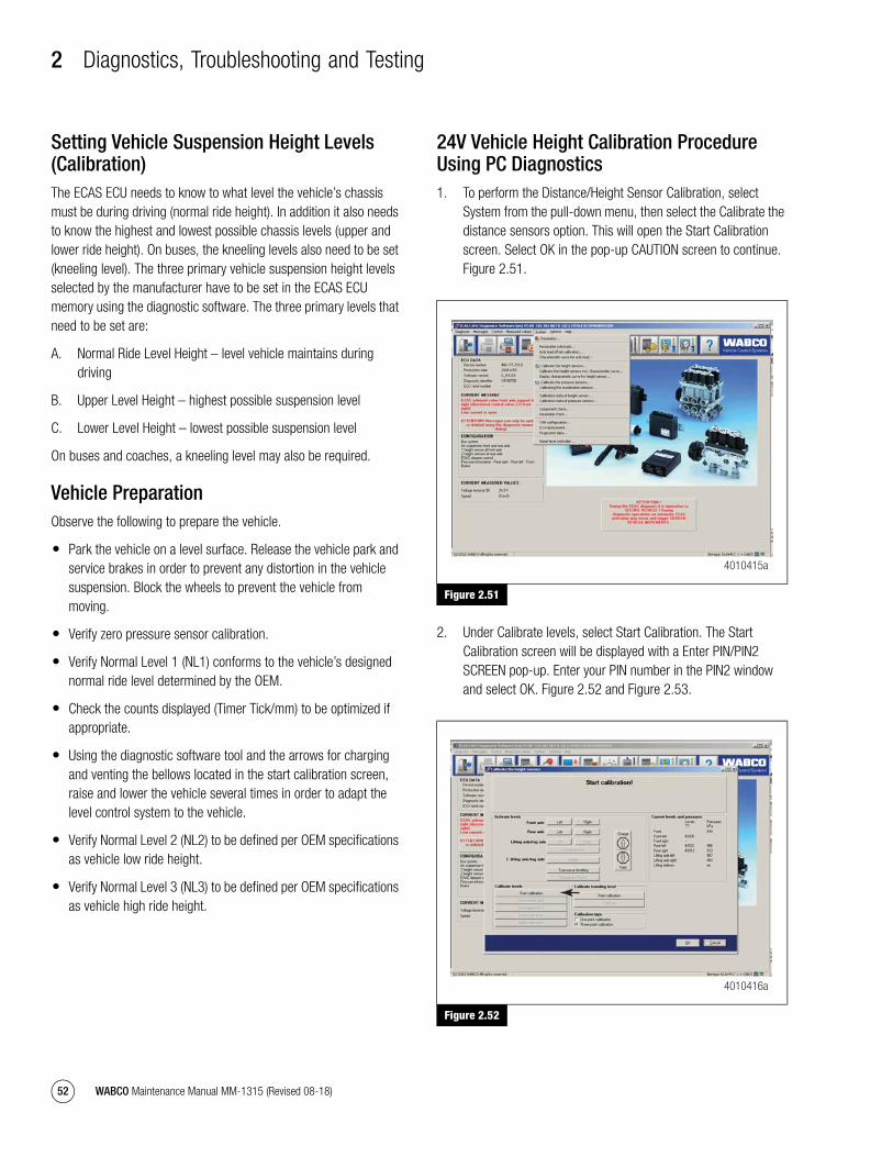
2 Diagnostics, Troubleshooting and Testing
52 WABCO Maintenance Manual MM-1315 (Revised 08-18)
Setting Vehicle Suspension Height Levels (Calibration)The ECAS ECU needs to know to what level the vehicle’s chassis must be during driving (normal ride height). In addition it also needs to know the highest and lowest possible chassis levels (upper and lower ride height). On buses, the kneeling levels also need to be set (kneeling level). The three primary vehicle suspension height levels selected by the manufacturer have to be set in the ECAS ECU memory using the diagnostic software. The three primary levels that need to be set are:
A. Normal Ride Level Height – level vehicle maintains during driving
B. Upper Level Height – highest possible suspension level
C. Lower Level Height – lowest possible suspension level
On buses and coaches, a kneeling level may also be required.
Vehicle PreparationObserve the following to prepare the vehicle.
� Park the vehicle on a level surface. Release the vehicle park and service brakes in order to prevent any distortion in the vehicle suspension. Block the wheels to prevent the vehicle from moving.
� Verify zero pressure sensor calibration.
� Verify Normal Level 1 (NL1) conforms to the vehicle’s designed normal ride level determined by the OEM.
� Check the counts displayed (Timer Tick/mm) to be optimized if appropriate.
� Using the diagnostic software tool and the arrows for charging and venting the bellows located in the start calibration screen, raise and lower the vehicle several times in order to adapt the level control system to the vehicle.
� Verify Normal Level 2 (NL2) to be defined per OEM specifications as vehicle low ride height.
� Verify Normal Level 3 (NL3) to be defined per OEM specifications as vehicle high ride height.
24V Vehicle Height Calibration Procedure Using PC Diagnostics1. To perform the Distance/Height Sensor Calibration, select
System from the pull-down menu, then select the Calibrate the distance sensors option. This will open the Start Calibration screen. Select OK in the pop-up CAUTION screen to continue. Figure 2.51.
Figure 2.51
2. Under Calibrate levels, select Start Calibration. The Start Calibration screen will be displayed with a Enter PIN/PIN2 SCREEN pop-up. Enter your PIN number in the PIN2 window and select OK. Figure 2.52 and Figure 2.53.
Figure 2.52
Figure 2.51
Figure 2.52
4010415a
4010416a
mm1315.bk.fm Page 52 Tuesday, July 9, 2019 7:23 PM
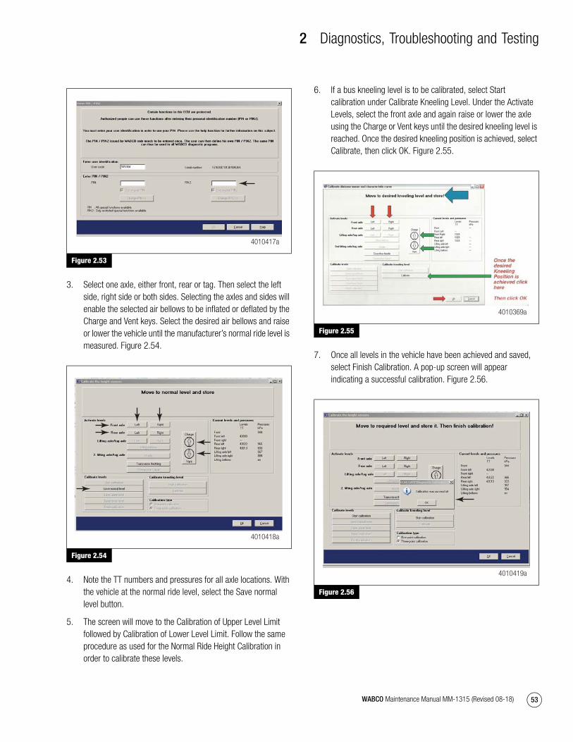
2 Diagnostics, Troubleshooting and Testing
53WABCO Maintenance Manual MM-1315 (Revised 08-18)
Figure 2.53
3. Select one axle, either front, rear or tag. Then select the left side, right side or both sides. Selecting the axles and sides will enable the selected air bellows to be inflated or deflated by the Charge and Vent keys. Select the desired air bellows and raise or lower the vehicle until the manufacturer’s normal ride level is measured. Figure 2.54.
Figure 2.54
4. Note the TT numbers and pressures for all axle locations. With the vehicle at the normal ride level, select the Save normal level button.
5. The screen will move to the Calibration of Upper Level Limit followed by Calibration of Lower Level Limit. Follow the same procedure as used for the Normal Ride Height Calibration in order to calibrate these levels.
6. If a bus kneeling level is to be calibrated, select Start calibration under Calibrate Kneeling Level. Under the Activate Levels, select the front axle and again raise or lower the axle using the Charge or Vent keys until the desired kneeling level is reached. Once the desired kneeling position is achieved, select Calibrate, then click OK. Figure 2.55.
Figure 2.55
7. Once all levels in the vehicle have been achieved and saved, select Finish Calibration. A pop-up screen will appear indicating a successful calibration. Figure 2.56.
Figure 2.56
Figure 2.53
Figure 2.54
4010417a
4010418a
Figure 2.55
Figure 2.56
4010369a
4010419a
mm1315.bk.fm Page 53 Tuesday, July 9, 2019 7:23 PM
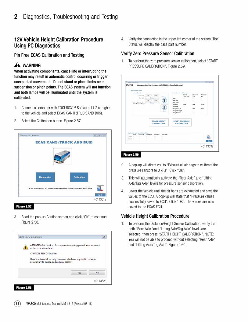
2 Diagnostics, Troubleshooting and Testing
54 WABCO Maintenance Manual MM-1315 (Revised 08-18)
12V Vehicle Height Calibration Procedure Using PC Diagnostics
Pin Free ECAS Calibration and Testing
WARNINGWhen activating components, cancelling or interrupting the function may result in automatic control occurring or trigger unexpected movements. Do not stand or place limbs near suspension or pinch points. The ECAS system will not function and both lamps will be illuminated until the system is calibrated.
1. Connect a computer with TOOLBOX™ Software 11.2 or higher to the vehicle and select ECAS CAN II (TRUCK AND BUS).
2. Select the Calibration button. Figure 2.57.
Figure 2.57
3. Read the pop-up Caution screen and click “OK” to continue. Figure 2.58.
Figure 2.58
4. Verify the connection in the upper left corner of the screen. The Status will display the base part number.
Verify Zero Pressure Sensor Calibration
1. To perform the zero pressure sensor calibration, select “START PRESSURE CALIBRATION”. Figure 2.59.
Figure 2.59
2. A pop-up will direct you to “Exhaust all air bags to calibrate the pressure sensors to 0 kPa”. Click “OK”.
3. This will automatically activate the “Rear Axle” and “Lifting Axle/Tag Axle” levels for pressure sensor calibration.
4. Lower the vehicle until the air bags are exhausted and save the values to the ECU. A pop-up will state that “Pressure values successfully saved to ECU”. Click “OK”. The values are now saved to the ECAS ECU.
Vehicle Height Calibration Procedure
1. To perform the Distance/Height Sensor Calibration, verify that both “Rear Axle “and “Lifting Axle/Tag Axle” levels are selected, then press “START HEIGHT CALIBRATION”. NOTE: You will not be able to proceed without selecting “Rear Axle” and “Lifting Axle/Tag Axle”. Figure 2.60.
Figure 2.57
Figure 2.58
4011361a
4011362a
Figure 2.59
4011363a
mm1315.bk.fm Page 54 Tuesday, July 9, 2019 7:23 PM
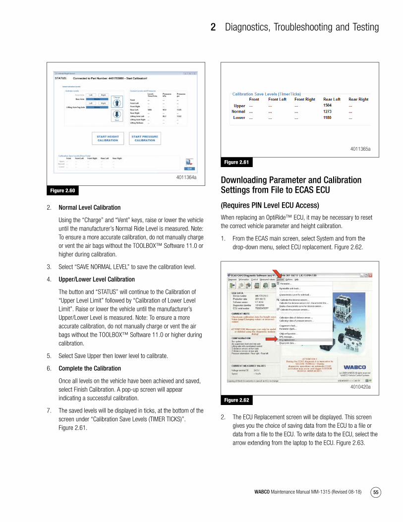
2 Diagnostics, Troubleshooting and Testing
55WABCO Maintenance Manual MM-1315 (Revised 08-18)
Figure 2.60
2. Normal Level Calibration
Using the “Charge” and “Vent” keys, raise or lower the vehicle until the manufacturer’s Normal Ride Level is measured. Note: To ensure a more accurate calibration, do not manually charge or vent the air bags without the TOOLBOX™ Software 11.0 or higher during calibration.
3. Select “SAVE NORMAL LEVEL” to save the calibration level.
4. Upper/Lower Level Calibration
The button and “STATUS” will continue to the Calibration of “Upper Level Limit” followed by “Calibration of Lower Level Limit”. Raise or lower the vehicle until the manufacturer’s Upper/Lower Level is measured. Note: To ensure a more accurate calibration, do not manually charge or vent the air bags without the TOOLBOX™ Software 11.0 or higher during calibration.
5. Select Save Upper then lower level to calibrate.
6. Complete the Calibration
Once all levels on the vehicle have been achieved and saved, select Finish Calibration. A pop-up screen will appear indicating a successful calibration.
7. The saved levels will be displayed in ticks, at the bottom of the screen under “Calibration Save Levels (TIMER TICKS)”. Figure 2.61.
Figure 2.61
Downloading Parameter and Calibration Settings from File to ECAS ECU
(Requires PIN Level ECU Access)
When replacing an OptiRide™ ECU, it may be necessary to reset the correct vehicle parameter and height calibration.
1. From the ECAS main screen, select System and from the drop-down menu, select ECU replacement. Figure 2.62.
Figure 2.62
2. The ECU Replacement screen will be displayed. This screen gives you the choice of saving data from the ECU to a file or data from a file to the ECU. To write data to the ECU, select the arrow extending from the laptop to the ECU. Figure 2.63.
Figure 2.60
4011364a
Figure 2.61
Figure 2.62
4011365a
4010420a
mm1315.bk.fm Page 55 Tuesday, July 9, 2019 7:23 PM
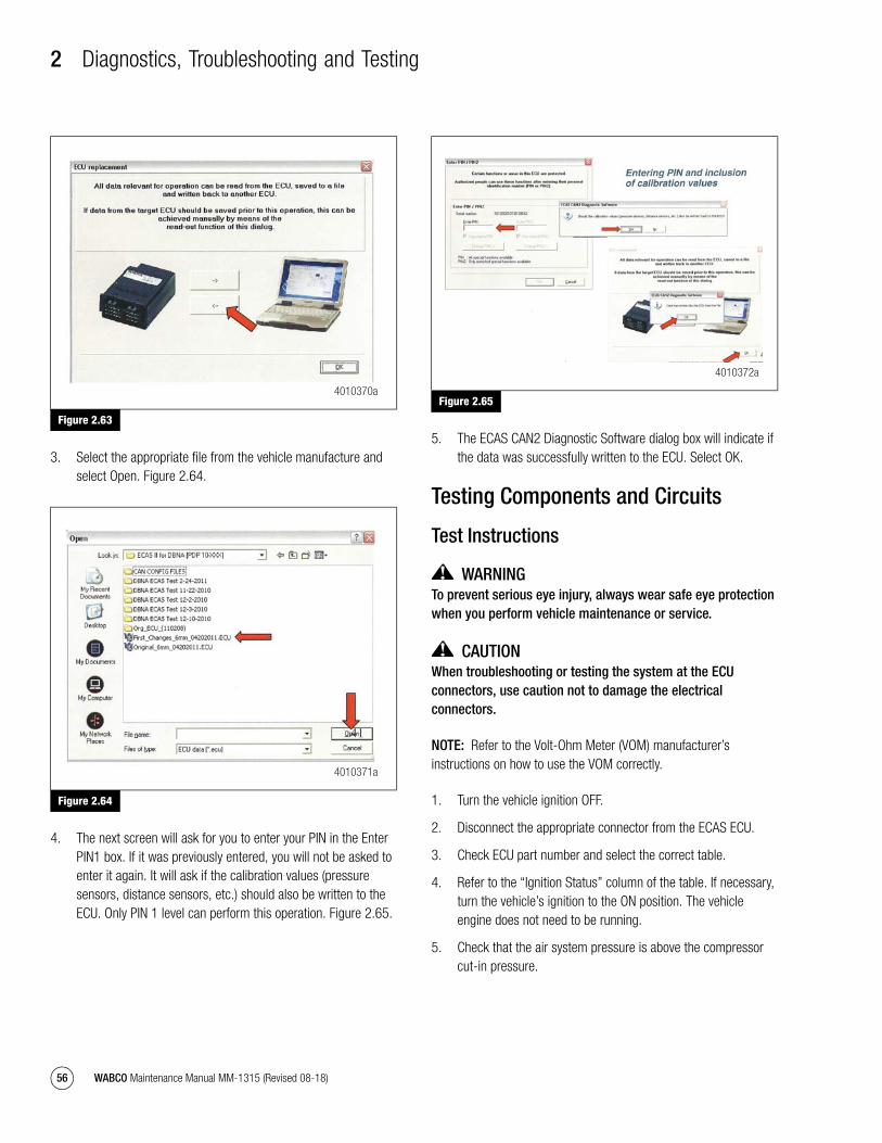
2 Diagnostics, Troubleshooting and Testing
56 WABCO Maintenance Manual MM-1315 (Revised 08-18)
Figure 2.63
3. Select the appropriate file from the vehicle manufacture and select Open. Figure 2.64.
Figure 2.64
4. The next screen will ask for you to enter your PIN in the Enter PIN1 box. If it was previously entered, you will not be asked to enter it again. It will ask if the calibration values (pressure sensors, distance sensors, etc.) should also be written to the ECU. Only PIN 1 level can perform this operation. Figure 2.65.
Figure 2.65
5. The ECAS CAN2 Diagnostic Software dialog box will indicate if the data was successfully written to the ECU. Select OK.
Testing Components and Circuits
Test Instructions
WARNINGTo prevent serious eye injury, always wear safe eye protection when you perform vehicle maintenance or service.
CAUTIONWhen troubleshooting or testing the system at the ECU connectors, use caution not to damage the electrical connectors.
NOTE: Refer to the Volt-Ohm Meter (VOM) manufacturer’s instructions on how to use the VOM correctly.
1. Turn the vehicle ignition OFF.
2. Disconnect the appropriate connector from the ECAS ECU.
3. Check ECU part number and select the correct table.
4. Refer to the “Ignition Status” column of the table. If necessary, turn the vehicle’s ignition to the ON position. The vehicle engine does not need to be running.
5. Check that the air system pressure is above the compressor cut-in pressure.
Figure 2.63
Figure 2.64
4010370a
4010371a
Figure 2.65
4010372a
mm1315.bk.fm Page 56 Tuesday, July 9, 2019 7:23 PM

2 Diagnostics, Troubleshooting and Testing
57WABCO Maintenance Manual MM-1315 (Revised 08-18)
6. Set the VOM to the appropriate setting that will accommodate the expected range listed in the “Measurement/Reaction” column of the table.
7. For each step in the table, compare the VOM reading or reaction with the acceptable values or reactions listed in the “Measurement/Reaction” column. Write down the results of your comparisons.
8. Repair or replace wiring or components when the measurements or reactions do not meet the required results. Confirm that the repairs or replacement provides the correct required results.
mm1315.bk.fm Page 57 Tuesday, July 9, 2019 7:23 PM
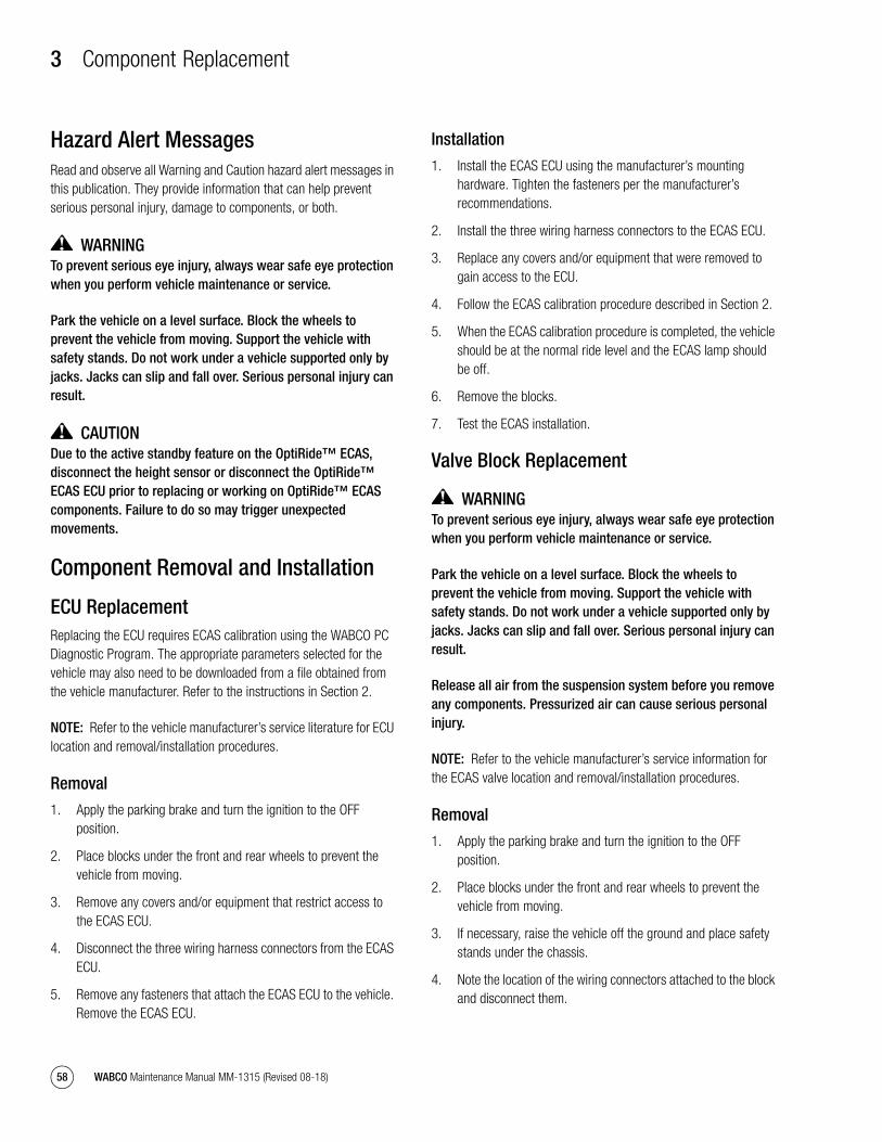
3 Component Replacement
58 WABCO Maintenance Manual MM-1315 (Revised 08-18)
3 Component ReplacementHazard Alert MessagesRead and observe all Warning and Caution hazard alert messages in this publication. They provide information that can help prevent serious personal injury, damage to components, or both.
WARNINGTo prevent serious eye injury, always wear safe eye protection when you perform vehicle maintenance or service.
Park the vehicle on a level surface. Block the wheels to prevent the vehicle from moving. Support the vehicle with safety stands. Do not work under a vehicle supported only by jacks. Jacks can slip and fall over. Serious personal injury can result.
CAUTIONDue to the active standby feature on the OptiRide™ ECAS, disconnect the height sensor or disconnect the OptiRide™ ECAS ECU prior to replacing or working on OptiRide™ ECAS components. Failure to do so may trigger unexpected movements.
Component Removal and Installation
ECU ReplacementReplacing the ECU requires ECAS calibration using the WABCO PC Diagnostic Program. The appropriate parameters selected for the vehicle may also need to be downloaded from a file obtained from the vehicle manufacturer. Refer to the instructions in Section 2.
NOTE: Refer to the vehicle manufacturer’s service literature for ECU location and removal/installation procedures.
Removal
1. Apply the parking brake and turn the ignition to the OFF position.
2. Place blocks under the front and rear wheels to prevent the vehicle from moving.
3. Remove any covers and/or equipment that restrict access to the ECAS ECU.
4. Disconnect the three wiring harness connectors from the ECAS ECU.
5. Remove any fasteners that attach the ECAS ECU to the vehicle. Remove the ECAS ECU.
Installation
1. Install the ECAS ECU using the manufacturer’s mounting hardware. Tighten the fasteners per the manufacturer’s recommendations.
2. Install the three wiring harness connectors to the ECAS ECU.
3. Replace any covers and/or equipment that were removed to gain access to the ECU.
4. Follow the ECAS calibration procedure described in Section 2.
5. When the ECAS calibration procedure is completed, the vehicle should be at the normal ride level and the ECAS lamp should be off.
6. Remove the blocks.
7. Test the ECAS installation.
Valve Block Replacement
WARNINGTo prevent serious eye injury, always wear safe eye protection when you perform vehicle maintenance or service.
Park the vehicle on a level surface. Block the wheels to prevent the vehicle from moving. Support the vehicle with safety stands. Do not work under a vehicle supported only by jacks. Jacks can slip and fall over. Serious personal injury can result.
Release all air from the suspension system before you remove any components. Pressurized air can cause serious personal injury.
NOTE: Refer to the vehicle manufacturer’s service information for the ECAS valve location and removal/installation procedures.
Removal
1. Apply the parking brake and turn the ignition to the OFF position.
2. Place blocks under the front and rear wheels to prevent the vehicle from moving.
3. If necessary, raise the vehicle off the ground and place safety stands under the chassis.
4. Note the location of the wiring connectors attached to the block and disconnect them.
mm1315.bk.fm Page 58 Tuesday, July 9, 2019 7:23 PM
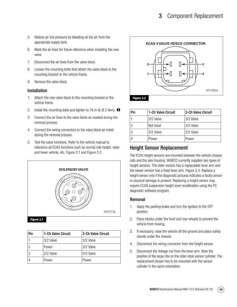
3 Component Replacement
59WABCO Maintenance Manual MM-1315 (Revised 08-18)
5. Relieve air line pressure by bleeding all the air from the appropriate supply tank.
6. Mark the air lines for future reference when installing the new valve.
7. Disconnect the air lines from the valve block.
8. Loosen the mounting bolts that attach the valve block to the mounting bracket or the vehicle frame.
9. Remove the valve block.
Installation
1. Attach the new valve block to the mounting bracket or the vehicle frame.
2. Install the mounting bolts and tighten to 76 in-lb (8.5 N�m). @
3. Connect the air lines to the valve block as marked during the removal process.
4. Connect the wiring connectors to the valve block as noted during the removal process.
5. Test the valve functions. Refer to the vehicle manual to reference all ECAS functions such as normal ride height, raise and lower vehicle, etc. Figure 3.1 and Figure 3.2.
Figure 3.1
Figure 3.2
Height Sensor ReplacementThe ECAS height sensors are mounted between the vehicle chassis rails and the axle housing. WABCO currently supplies two types of height sensors. The older version has a replaceable lever arm and the newer version has a fixed lever arm. Figure 3.3. Replace a height sensor only if the diagnostic process indicates a faulty sensor or physical damage is present. Replacing a height sensor may require ECAS suspension height level recalibration using the PC diagnostic software program.
Removal
1. Apply the parking brake and turn the ignition to the OFF position.
2. Place blocks under the front and rear wheels to prevent the vehicle from moving.
3. If necessary, raise the vehicle off the ground and place safety stands under the chassis.
4. Disconnect the wiring connector from the height sensor.
5. Disconnect the linkage rod from the lever arm. Note the position of the large ribs on the older-style sensor cylinder. The replacement sensor has to be mounted with the sensor cylinder in the same orientation.
Figure 3.1
Pin 1-Ch Valve Circuit 2-Ch Valve Circuit
1 3/2 Valve 3/2 Valve
2 Power 2/2 Valve
3 2/2 Valve 2/2 Valve
4 Power Power
4007213a
1
3
2
4
SOLENOID VALVE
Figure 3.2
Pin 1-Ch Valve Circuit 2-Ch Valve Circuit
1 3/2 Valve 3/2 Valve
2 Not Used 2/2 Valve
3 2/2 Valve 2/2 Valve
4 Power Power
4012650a
2
ECAS 4 VALVE HDSCS CONNECTOR
4
3
1
mm1315.bk.fm Page 59 Tuesday, July 9, 2019 7:23 PM
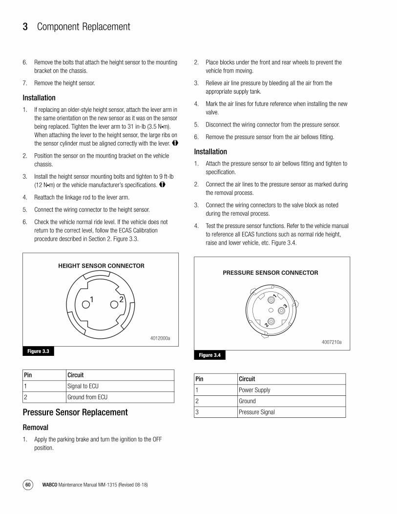
3 Component Replacement
60 WABCO Maintenance Manual MM-1315 (Revised 08-18)
6. Remove the bolts that attach the height sensor to the mounting bracket on the chassis.
7. Remove the height sensor.
Installation
1. If replacing an older-style height sensor, attach the lever arm in the same orientation on the new sensor as it was on the sensor being replaced. Tighten the lever arm to 31 in-lb (3.5 N�m). When attaching the lever to the height sensor, the large ribs on the sensor cylinder must be aligned correctly with the lever. @
2. Position the sensor on the mounting bracket on the vehicle chassis.
3. Install the height sensor mounting bolts and tighten to 9 ft-lb (12 N�m) or the vehicle manufacturer’s specifications. @
4. Reattach the linkage rod to the lever arm.
5. Connect the wiring connector to the height sensor.
6. Check the vehicle normal ride level. If the vehicle does not return to the correct level, follow the ECAS Calibration procedure described in Section 2. Figure 3.3.
Figure 3.3
Pressure Sensor Replacement
Removal
1. Apply the parking brake and turn the ignition to the OFF position.
2. Place blocks under the front and rear wheels to prevent the vehicle from moving.
3. Relieve air line pressure by bleeding all the air from the appropriate supply tank.
4. Mark the air lines for future reference when installing the new valve.
5. Disconnect the wiring connector from the pressure sensor.
6. Remove the pressure sensor from the air bellows fitting.
Installation
1. Attach the pressure sensor to air bellows fitting and tighten to specification.
2. Connect the air lines to the pressure sensor as marked during the removal process.
3. Connect the wiring connectors to the valve block as noted during the removal process.
4. Test the pressure sensor functions. Refer to the vehicle manual to reference all ECAS functions such as normal ride height, raise and lower vehicle, etc. Figure 3.4.
Figure 3.4
Figure 3.3
Pin Circuit
1 Signal to ECU
2 Ground from ECU
4012000a
HEIGHT SENSOR CONNECTOR
21
Figure 3.4
Pin Circuit
1 Power Supply
2 Ground
3 Pressure Signal
4007210a
1
3
2
PRESSURE SENSOR CONNECTOR
mm1315.bk.fm Page 60 Tuesday, July 9, 2019 7:23 PM

4 System and Component Diagrams
61WABCO Maintenance Manual MM-1315 (Revised 08-18)
4 System and Component DiagramsDiagramsECU Part Number 446 170 210 0 Connection Scheme for Pressure Ratio
Figure 4.1
Figure 4.1
4010359a
1
2
3
4
5
6
7
8
9
10
11
12
13
14
15
16
17
18
5A
15A
Vcc, ignition
Vcc, battery
ground
CAN L
CAN H
- reserved -
- reserved -
- reserved -
- reserved -
- reserved -
- reserved -
- reserved -
- not used -
- not used -
- not used -
- not used -
Vcc
DISTANCE SENSORfront axle left
transverse acc. sensor
tag axle right
PRESSURE SENSORStag axle left
PRESSURE SENSORSrear axle right
tag axle right/lifting
central 3/2 front axle
tag axle left/lowering
rear axle left
front axle
sensors ground
pressure sensors Vcc
front axle right
rear axle right
solenoid valves Vcc
front axle right
lateral throttle
rear axle right
front axle left
central 3/2 rear axle
SOLENOID VALVESrear axle left
DISTANCE SENSORSrear axle left
SOLENOID VALVES
pin coding for secondECU address
pressure switch
HF-GND
X1
X1
1
2
3
10 10
11
12
13
14
15
4
5
8
9
1
7
2
3
3
1
2
6
3
4
5
7
8
9
7
12
1
2
3
4
5
6
17
16
13
15
11
8
14
9
18
4
5
6
7
8
9
10
11
12
13
14
15
X2
X2
X3
UP
1
2
3
4
5
6
7
8
9
X3
UP
UP
UP
UP
Ua
mm1315.bk.fm Page 61 Tuesday, July 9, 2019 7:23 PM

4 System and Component Diagrams
62 WABCO Maintenance Manual MM-1315 (Revised 08-18)
ECU Part Number 446 170 210 0 Connection Scheme for Pressure Equality
Figure 4.2
Figure 4.2
4010360a
1
2
3
4
5
6
7
8
9
10
11
12
13
14
15
16
17
18
5A
15A
Vcc, ignition
Vcc, battery
ground
CAN L
CAN H
- reserved -
- reserved -
- reserved -
- reserved -
Vcc, sidewalk
- reserved -
- reserved -
- not used -
- not used -
- not used -
- not used -
- reserved -
Vcc, sidewalk
R2
R3
R1
DISTANCE SENSORfront axle left
transverse acc. sensor
sidewalk detection
PRESSURE SENSORSrear axle right
tag axle right/lifting
central 3/2 front axle
tag axle left/lowering
rear axle left
front axle
sensors ground
pressure sensors Vcc
front axle right
rear axle right
solenoid valves Vcc
front axle right
lateral throttle
rear axle right
front axle left
central 3/2 rear axle
SOLENOID VALVESrear axle left
DISTANCE SENSORSrear axle left
SOLENOID VALVES
pin coding for secondECU address
pressure switch
HF-GND
X1
X1
1
2
3
10 10
11
12
13
14
15
4
5
8
9
1
7
2
3
3
1
2
6
3
5
4
8
9
7
12
1
2
3
4
5
6
17
16
13
15
11
8
14
9
18
4
5
6
7
8
9
10
11
12
13
14
15
X2
X2
X3
UP
1
2
3
4
5
6
7
8
9
X3
7
UP
UP
Ua
mm1315.bk.fm Page 62 Tuesday, July 9, 2019 7:23 PM
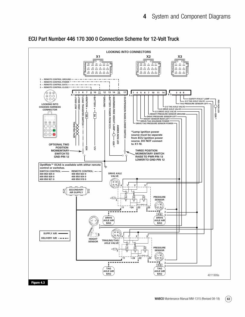
4 System and Component Diagrams
63WABCO Maintenance Manual MM-1315 (Revised 08-18)
ECU Part Number 446 170 300 0 Connection Scheme for 12-Volt Truck
Figure 4.3
Figure 4.3
SWITCH CONTROL:
400 850 925 0
400 850 926 0
400 850 921 0
1 3 6 7 8 10 11 12 13 14 15 17 1 4 5 6 7 10 11 14 3 6 8
J1
939
HIG
H
J1
93
9 L
OW
TW
IST
ED
PA
IR
LO
AD
TR
AN
SF
ER
SW
ITC
H
IGN
ITIO
N +
10
A
BA
TT
ER
Y +
5A
GR
OU
ND
-
BA
TT
ER
Y P
OW
ER
FR
OM
EC
U
12V
IGN
SU
SP
EN
SIO
N R
AIS
E/L
OW
ER
SW
ITC
H
WA
RN
ING
/RID
E H
EIG
HT
LA
MP
AM
BE
R-N
ON
LE
D
IGN
*
RE
D-N
ON
LE
D
IGN
*
TAG PRESSURE SENSOR LEFT
3/2 TAG AXLE VALVE
1
2
3
1
2
3
DRIVE
AXLE AIR
BAG
DRIVE
AXLE AIR
BAG
HEIGHT
SENSOR
PRESSURE
SENSOR
TRAILING/TAG
AXLE VALVE
P/S
22 232411
3
4 21 3
22 232411
3
4 21 3
TAG
AXLE AIR
BAG
TAG
AXLE AIR
BAG
P/S
2 — REMOTE CONTROL GROUND
1 — REMOTE CONTROL POWER
4 — REMOTE CONTROL DATA
3 — REMOTE CONTROL CLOCK
DRIVE/TAG PRESSURE SENSOR POWER
DRIVE/TAG SOLENOID POWER
HEIGHT SENSOR REAR LEFT
DRIVE PRESSURE SENSOR LEFT
HEIGHT/PRESSURE SENSOR GROUND
2/2 DRIVE AXLE VALVE
3/2 DRIVE AXLE VALVE
2/2 TAG AXLE VALVE
1 2
4
3
X-2X-1
LOOKING INTO
CHASSIS HARNESS
CONNECTOR
X-3
21
LOOKING INTO CONNECTORS
SUPPLY AIR:
DELIVERY AIR:
DRIVE AXLE
VALVE
SECONDARY
AIR SUPPLY
PRESSURE
SENSOR
OPTIONAL TWOPOSITION
MOMEMTARYSWITCH TOGND-PIN 12
THREE POSITIONMOMENTARY SWITCHRAISE TO PWR-PIN 13LOWER TO GND-PIN 12
*Lamp ignition powersource must be separatefrom ECU ignition powersource. DO NOT connectto X1-10.
OptiRide™ ECAS is available with either remotecontrol or switches.
SAFETY/FAULT LAMP
REMOTE CONTROL:
400 850 923 0
400 850 924 0
400 850 919 0
4011999a
M1 M1
STOP
1
32
1
32
21
3 2
1 4
4
X3
17
5 28
6 39
3 2
1 4
7
X2
410
8 511
9 612
13
14
15
1
2
3
7
X1
410
8 511
9 612
13
14
15
16
17
18
1
2
3
mm1315.bk.fm Page 63 Tuesday, July 9, 2019 7:23 PM

4 System and Component Diagrams
64 WABCO Maintenance Manual MM-1315 (Revised 08-18)
ECU Part Number 446 170 300 0 Connection Scheme for 12-Volt Shuttle Bus (4x2)
Figure 4.4
Figure 4.4
4012651a
X1(18 PIN)
X2(15 PIN)X3
(9 PIN)
LAMPS SOLENOID VALVE 472 890 070 0
HEIGHT SENSORS 441 050 ...
97541115108
ECU
12
AA
A
71031175
8 6 9
4 4
5
1 73
1011
2
1314
-RE
SE
RV
ED
-
VC
C.
IGN
ITIO
N
VC
C.
IGN
ITIO
NV
CC
.IG
NIT
ION
SA
FE
TY
NO
RM
AL
LE
VE
L 1
/11
/111
SW
ITC
H R
AIS
ING
/LO
WE
RIN
G
CA
N L
OW
CA
N H
IGH
VC
C. IG
NIT
ION
VC
C. B
AT
TE
RY
GR
OU
ND
WA
RN
ING
LA
MP
RA
LE
FT
RA
LE
FT
SE
NS
OR
S G
RO
UN
D
VC
C.
SO
LE
NO
IDV
ALV
E
CE
NT
RA
L 3
/2
FA
FA
6.2
23 22 11
6.3
3
6.1
1 1
2
6.4
1 CENTRAL COLLECTING POINT, DISTANCE <1 M FROM ECU
HEIGHT SENSOR CABLES SHOULD BE TWISTED IN PAIRS
2 PIN 6.4 CONNECTED WITH 3
3 +UB FOR SOLENOID VALVES
4 ACCORDING TO SAE J1939
5 IGNITION
6 SOLENOID VALVE FRONT AXLE WITH CONNECTION TO PIN X 2/15
7 DISTANCE SENSOR FRONT AXLE WITH CONNECTION TO PIN X 2/9
8 SOLENOID VALVE REAR AXLE WITH CONNECTION TO PIN X 2/10
9 DISTANCE SENSOR REAR AXLE LEFT WITH CONNECTION TO PIN X 2/5
10 VALVE DELIVERY PORT 22 WITH CONNECTION TO FRONT AXLE BELLOWS
11 VALVE DELIVERY PORT 23 WITH CONNECTION TO REAR AXLE BELLOWS
ALL DECLARATIONS OF NOMINAL WIDTHS/CROSS SECTIONS ARE RECOMMENDATIONS.
A = 2.5 MM 2
ALL ELECTRIC WIRES WITHOUT DECLARATION OF CROSS SECTION A = 0.75 MM
ALL PIPES WITHOUT DECLARATION OF NOMINAL WIDTHS NW = 7 MM
mm1315.bk.fm Page 64 Tuesday, July 9, 2019 7:23 PM

4 System and Component Diagrams
65WABCO Maintenance Manual MM-1315 (Revised 08-18)
ECU Part Number 446 170 300 0 Connection Scheme for 12-Volt Lift Axle Truck with ECAS 4 Valve
Figure 4.5
Figure 4.5
4012652a
8 11
DA
TA
CL
OC
K
10
IGN
ITIO
N K
EY
7
+ -12V
BA
TT
ER
Y
ELECTRONIC CONTROL UNIT 446 170 300 0
1 CENTRAL COLLECTING POINT, DISTANCE <1 M FROM ECU
HEIGHT SENSOR CABLES SHOULD BE TWISTED IN PAIRS
2 PIN 6.2 OR PIN 6.4 CONNECTED WITH 3
3 +UB FOR SOLENOID VALVES
4 ACCORDING TO SAE J1939
5 SEPARATE CONNECTION REQUIRED
6 IGNITION
PAR. 2.2 = 0 PAR. 2.2 = 1
7 PRESSURE SENSOR DRIVING AXLE WITH CONNECTION TO PIN X 2/6 PIN X 2/2
8 DISTANCE SENSOR DRIVING AXLE WITH CONNECTION TO PIN X 2/5 PIN X 2/8
9 SOLENOID VALVE DRIVING AXLE WITH CONNECTION TO PIN X 2/10 PIN X 2/13
10 PRESSURE SENSOR TRAILING AXLE WITH CONNECTION TO PIN X 3/3 PIN X 3/4
11 SOLENOID VALVE TRAILING AXLE WITH CONNECTION TO PIN X 2/14 PIN X 2/12
12 SWITCH PRESSURE RATION 1/11 FOR PARAMETER 13.6 = 0 PIN X 1/17
ALL DECLARATIONS OF NOMINAL WIDTHS/CROSS SECTIONS
ARE RECOMMENDATIONS.
ALL ELECTRIC WIRES WITHOUT DECLARATION OF CROSS
SECTION A = 0.75 MM
ALL PIPES WITHOUT DECLARATION OF NOMINAL WIDTHS NW = 7 MM
LEFT RIGHT
1 2 3 4
STOP
M1 M2
151312X1 51 2 3
LO
W
HF
-GN
D
HIG
H
CA
N
NO
RM
AL
LE
VE
L I
/II/
III
GR
OU
ND
+U
B
(SA
E J
1939)
446 056 ... .
14
WA
RN
ING
LA
MP
5A
15
A 2A
=2
.5 M
M
X2176
TR
AC
TIO
N H
EL
P
RA
ISIN
G/L
OW
ER
ING
FO
R P
AR
AM
ET
ER
13
.6 =
1
MA
X.2
W
5 6 14
DRIVING-
AXLE
10
DRIVING-
AXLE
44
1 0
44
...
.
1
23
1
3 2
11
UP
UP
34 7 1 6X3
NW10
2A
=2
.5 M
M
4 4 4 3
1
5
1
1
LIFTING-
AXLE
8
LEFT RIGHT
6
12
5
472 890 070 0
LIFTING-
AXLE
8 9111 10
23 22
472 890 076 0
6.4
1121
6.1
3
6.3
2
RIGHTLEFT
SA
FE
TY
LA
MP
MA
X.2
W
2A
=2
.5 M
M 7
4
LIF
T A
XL
E
3
6.16.3
6.4
6.2
23 22
1121
3
1
5
3
21
UP
LIFTING-
BELLOWS
51 9
6
LIF
TA
XL
E L
AM
PM
AX
.2W
441 050 ... .
mm1315.bk.fm Page 65 Tuesday, July 9, 2019 7:23 PM

4 System and Component Diagrams
66 WABCO Maintenance Manual MM-1315 (Revised 08-18)
ECU Part Number 446 170 300 0 Connection Scheme for 12-Volt Lift Axle Truck with ECAS 3 Valve
Figure 4.6
Figure 4.6
4012653a
8 11
DA
TA
CL
OC
K
10
IGN
ITIO
N K
EY
7
+ -12V
BA
TT
ER
Y
ELECTRONIC CONTROL UNIT 446 170 300 0
1 CENTRAL COLLECTING POINT, DISTANCE <1 M FROM ECU
HEIGHT SENSOR CABLES SHOULD BE TWISTED IN PAIRS
2 PIN 6.2 OR PIN 6.4 CONNECTED WITH 3
3 +UB FOR SOLENOID VALVES
4 ACCORDING TO SAE J1939
5 SEPARATE CONNECTION REQUIRED
6 IGNITION
PAR. 2.2 = 0 PAR. 2.2 = 1
7 PRESSURE SENSOR DRIVING AXLE WITH CONNECTION TO PIN X 2/6 PIN X 2/2
8 DISTANCE SENSOR DRIVING AXLE WITH CONNECTION TO PIN X 2/5 PIN X 2/8
9 SOLENOID VALVE DRIVING AXLE WITH CONNECTION TO PIN X 2/10 PIN X 2/13
10 PRESSURE SENSOR TRAILING AXLE WITH CONNECTION TO PIN X 3/3 PIN X 3/4
11 SOLENOID VALVE TRAILING AXLE WITH CONNECTION TO PIN X 2/14 PIN X 2/12
ALL DECLARATIONS OF NOMINAL WIDTHS/CROSS SECTIONS
ARE RECOMMENDATIONS.
ALL ELECTRIC WIRES WITHOUT DECLARATION OF CROSS
SECTION A = 0.75 MM
ALL PIPES WITHOUT DECLARATION OF NOMINAL WIDTHS NW = 7 MM
LEFT RIGHT
1 2 3 4
STOP
M1 M2
151312X1 51 2 3
LO
W
HF
-GN
D
HIG
H
CA
N
NO
RM
AL
LE
VE
L I
/II/
III
GR
OU
ND
+U
B
(SA
E J
1939)
446 056 ... .
14
WA
RN
ING
LA
MP
5A
15
A 2A
=2
.5 M
M
X2176
TR
AC
TIO
N H
EL
P
RA
ISIN
G/L
OW
ER
ING
MA
X.2
W
5 6 14
DRIVING-
AXLE
10
DRIVING-
AXLE
44
1 0
44
...
.
1
23
1
3 2
11
UP
UP
34 7 1 6X3
NW10
2A
=2
.5 M
M
4 4 4 3
1
5
1
1
TRAILING-
AXLE
8
LEFT RIGHT
6
5
472 880 074 0
TRAILING-
AXLE
8 9111 10
23 22
472 880 073 0
6.4
11216.2
6.1
3
6.3
2
RIGHTLEFT
SA
FE
TY
LA
MP
MA
X.2
W
2A
=2
.5 M
M 7
4L
IFT
AX
LE
3
6.16.3
6.4
6.2
23 22
1121
3
1
5
3
21
UP
LIFTING-
BELLOWS
51 9
6
LIF
TA
XL
E L
AM
PM
AX
.2W
441 050 ... .
mm1315.bk.fm Page 66 Tuesday, July 9, 2019 7:23 PM
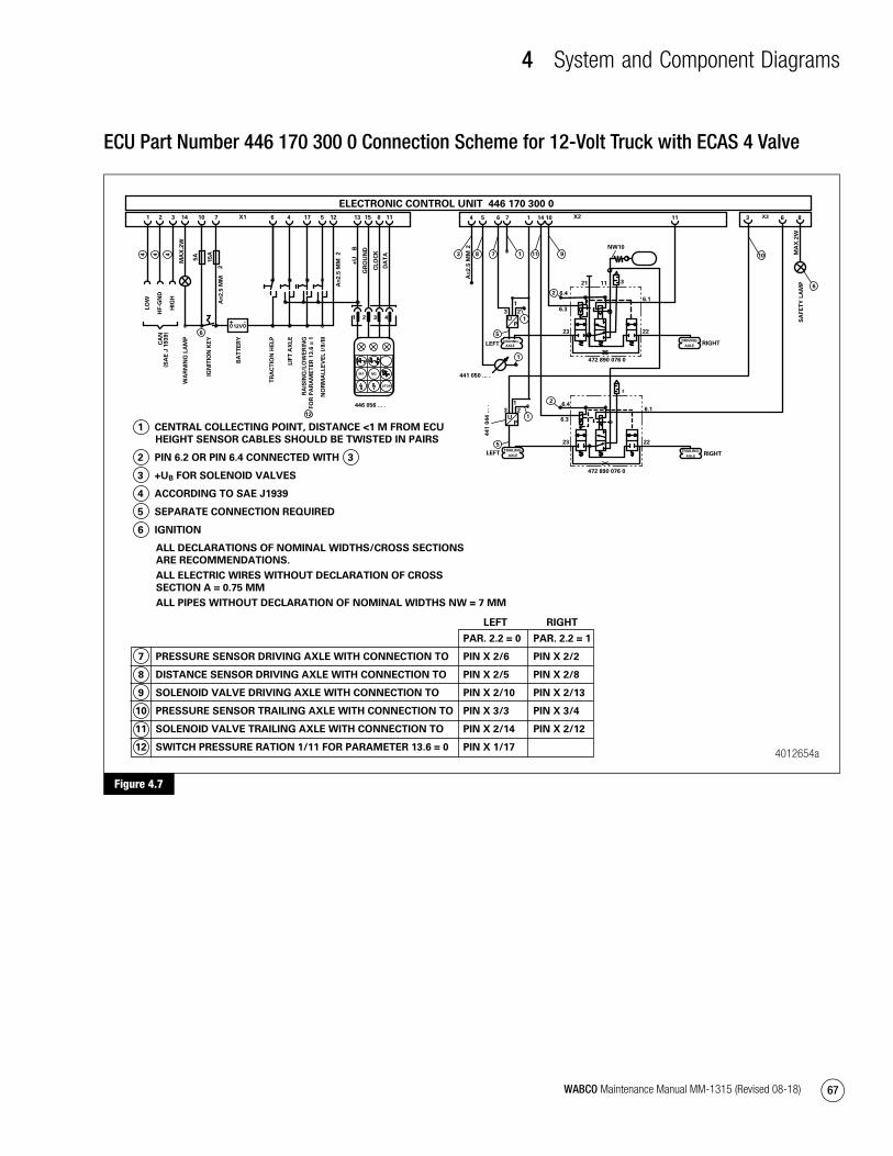
4 System and Component Diagrams
67WABCO Maintenance Manual MM-1315 (Revised 08-18)
ECU Part Number 446 170 300 0 Connection Scheme for 12-Volt Truck with ECAS 4 Valve
Figure 4.7
Figure 4.7
4012654a
8 11
DA
TA
CL
OC
K
10
IGN
ITIO
N K
EY
7
+ -12V
BA
TT
ER
Y
ELECTRONIC CONTROL UNIT 446 170 300 0
1 CENTRAL COLLECTING POINT, DISTANCE <1 M FROM ECU
HEIGHT SENSOR CABLES SHOULD BE TWISTED IN PAIRS
2 PIN 6.2 OR PIN 6.4 CONNECTED WITH 3
3 +UB FOR SOLENOID VALVES
4 ACCORDING TO SAE J1939
5 SEPARATE CONNECTION REQUIRED
6 IGNITION
PAR. 2.2 = 0 PAR. 2.2 = 1
7 PRESSURE SENSOR DRIVING AXLE WITH CONNECTION TO PIN X 2/6 PIN X 2/2
8 DISTANCE SENSOR DRIVING AXLE WITH CONNECTION TO PIN X 2/5 PIN X 2/8
9 SOLENOID VALVE DRIVING AXLE WITH CONNECTION TO PIN X 2/10 PIN X 2/13
10 PRESSURE SENSOR TRAILING AXLE WITH CONNECTION TO PIN X 3/3 PIN X 3/4
11 SOLENOID VALVE TRAILING AXLE WITH CONNECTION TO PIN X 2/14 PIN X 2/12
12 SWITCH PRESSURE RATION 1/11 FOR PARAMETER 13.6 = 0 PIN X 1/17
ALL DECLARATIONS OF NOMINAL WIDTHS/CROSS SECTIONS
ARE RECOMMENDATIONS.
ALL ELECTRIC WIRES WITHOUT DECLARATION OF CROSS
SECTION A = 0.75 MM
ALL PIPES WITHOUT DECLARATION OF NOMINAL WIDTHS NW = 7 MM
LEFT RIGHT
1 2 3 4
STOP
M1 M2
151312X1 51 2 3
LO
W
HF
-GN
D
HIG
H
CA
N
NO
RM
AL
LE
VE
L I
/II/
III
GR
OU
ND
+U
B
(SA
E J
1939)
446 056 ... .
14
WA
RN
ING
LA
MP
5A
15
A 2A
=2
.5 M
M
X2176
TR
AC
TIO
N H
EL
P
RA
ISIN
G/L
OW
ER
ING
FO
R P
AR
AM
ET
ER
13
.6 =
1
MA
X.2
W
5 6 14
DRIVING-
AXLE
10
DRIVING-
AXLE
44
1 0
44
...
.
1
23
1
3 2
11
UP
UP
34 7 1 6X3
NW10
2A
=2
.5 M
M
4 4 4 3
1
5
1
1
TRAILING-
AXLE
8
LEFT RIGHT
6
12
5
472 890 076 0
TRAILING-
AXLE
8 9111 10
23 22
472 890 076 0
6.4
1121
6.1
3
6.3
2
RIGHTLEFT
SA
FE
TY
LA
MP
MA
X.2
W
2A
=2
.5 M
M 7
4
LIF
T A
XL
E
2
6.1
6.3
6.4
23 22
3
6
441 050 ... .
mm1315.bk.fm Page 67 Tuesday, July 9, 2019 7:23 PM

© 2018 WABCO North America – All rights reserved – MM-1315 / 08.2018
About WABCO
WABCO (NYSE: WBC) is the leading global supplier of braking control systems and other advanced technologies that improve the safety, efficiency and connectivity of commercial vehicles. Originating from the Westinghouse Air Brake Company founded nearly 150 years ago, WABCO is powerfully “Mobilizing Vehicle Intelligence” to support the increasingly autonomous, connected and electric future of the commercial vehicle industry. WABCO continues to pioneer innovations to address key technology milestones in autonomous mobility and apply its extensive expertise to integrate the complex control and fail-safe systems required to efficiently and safely govern vehicle dynamics at every stage of a vehicle’s journey – on the highway, in the city and at the depot. Today, leading truck, bus and trailer brands worldwide rely on WABCO’s differentiating technologies. Powered by its vision for accident-free driving and greener transportation solutions, WABCO is also at the forefront of advanced fleet management systems and digital services that contribute to commercial fleet efficiency. In 2018, WABCO reported sales of over $3.8 billion and has more than 16,000 employees in 40 countries. For more information, visit www.wabco-na.com.
mm1315 back cover.indd 44 7/9/2019 7:30:20 PM