optisonic 7300 - forbes marshall 7300 technical datasheet ultrasonic gas flowmeter • wide...
TRANSCRIPT

OPTISONIC 7300OPTISONIC 7300OPTISONIC 7300OPTISONIC 7300 Technical DatasheetTechnical DatasheetTechnical DatasheetTechnical Datasheet
Ultrasonic gas flowmeter
• Wide application range• No moving parts and no pressure loss• Complete solution for gasflow measurement
© KROHNE 06/2011 - 4001344701- TD OPTISONIC 7300 R01 en
CONTENTS
2 www.krohne.com 06/2011 - 4001344701- TD OPTISONIC 7300 R01 en
OPTISONIC 7300
1 Product features 3
1.1 Ultrasonic process gas flow measurement..................................................................... 31.2 Variants............................................................................................................................. 51.3 Features............................................................................................................................ 61.4 Measuring principle.......................................................................................................... 7
2 Technical data 8
2.1 Technical data................................................................................................................... 82.2 Dimensions and weights ................................................................................................ 18
2.2.1 Gas flow sensor, carbon steel .............................................................................................. 182.2.2 Converter housing................................................................................................................. 21
3 Installation 22
3.1 Intended use ................................................................................................................... 223.2 Environmental requirements......................................................................................... 223.3 Installation requirements signal converter ................................................................... 223.4 Installation requirements sensor .................................................................................. 22
3.4.1 Inlet and outlet ...................................................................................................................... 233.4.2 Vertical mounting.................................................................................................................. 233.4.3 Mounting position.................................................................................................................. 233.4.4 Vibration ................................................................................................................................ 243.4.5 Control valve ......................................................................................................................... 243.4.6 Flange deviation .................................................................................................................... 253.4.7 T-section ............................................................................................................................... 25
4 Electrical connections 26
4.1 Safety instructions.......................................................................................................... 264.2 Power supply .................................................................................................................. 264.3 Inputs and outputs, overview ......................................................................................... 27
4.3.1 Combinations of the inputs/outputs (I/Os) ........................................................................... 274.3.2 Description of the CG number .............................................................................................. 284.3.3 Fixed, non-alterable input/output versions.......................................................................... 294.3.4 Alterable input/output versions............................................................................................ 30
5 Application form 31
6 Notes 33

PRODUCT FEATURES 1
3
OPTISONIC 7300
www.krohne.com06/2011 - 4001344701- TD OPTISONIC 7300 R01 en
1.1 Ultrasonic process gas flow measurement
The OPTISONIC 7300OPTISONIC 7300OPTISONIC 7300OPTISONIC 7300 offers an ultrasonic measurement system dedicated for process gas flow applications. The OPTISONIC 7300OPTISONIC 7300OPTISONIC 7300OPTISONIC 7300 does not have the limitations that are usually associated with traditional gas flow meters like periodical recalibrations, maintenance, pressure loss and a limited flow range. The OPTISONIC 7300OPTISONIC 7300OPTISONIC 7300OPTISONIC 7300 combines the advantages of ultrasonic measurement in a way that it is efficient, reliable and easy to use.
1 Current input option for calculation to standard conditions2 Process connections

1 PRODUCT FEATURES
4
OPTISONIC 7300
www.krohne.com 06/2011 - 4001344701- TD OPTISONIC 7300 R01 en
Highlights• Wide flow range• Independent of gas density and composition to a large extend• No maintenance• No recalibration• Integrated volume correction to standard conditions using P, T measurement• No moving parts, no pressure loss
Industries• Chemicals• Petrochemicals• Power plants• Oil & Gas
Applications• General process control• Hydrocarbon gases in petrochemical plants• Process gases in chemical plants• Production of natural gas• Consumption / usage of natural gas• Usage of fuel gas• Air flows

PRODUCT FEATURES 1
5
OPTISONIC 7300
www.krohne.com06/2011 - 4001344701- TD OPTISONIC 7300 R01 en
1.2 Variants
Version and some general examples
Version• Available as compact version.
Connection options• Standard flange range available up to
ASME 900 lb / PN 40. Others on request.
Correction to standard conditions (optional)• Gas flow volume correction to standard conditions• Using temperature and pressure inputs
GFC 300 ultrasonic signal converter• Ex / non-Ex, IP 66/67
1 PRODUCT FEATURES
6
OPTISONIC 7300
www.krohne.com 06/2011 - 4001344701- TD OPTISONIC 7300 R01 en
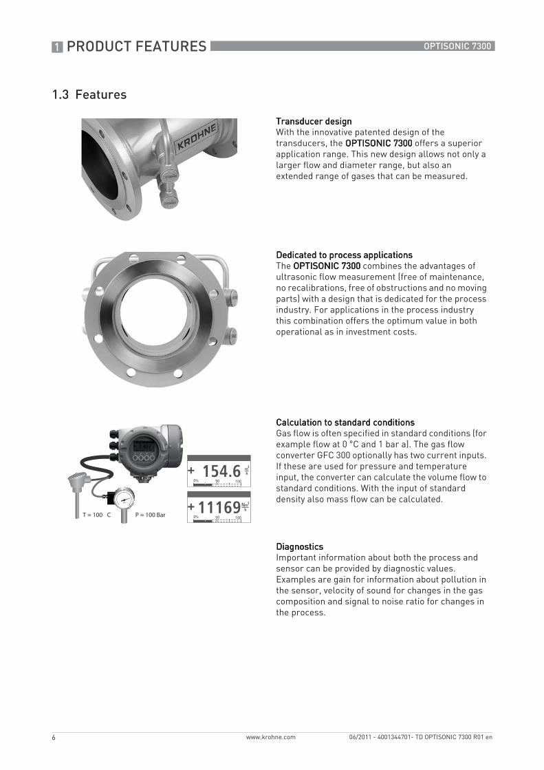
1.3 Features
Transducer designTransducer designTransducer designTransducer designWith the innovative patented design of the transducers, the OPTISONIC 7300OPTISONIC 7300OPTISONIC 7300OPTISONIC 7300 offers a superior application range. This new design allows not only a larger flow and diameter range, but also an extended range of gases that can be measured.
Dedicated to process applicationsDedicated to process applicationsDedicated to process applicationsDedicated to process applicationsThe OPTISONIC 7300OPTISONIC 7300OPTISONIC 7300OPTISONIC 7300 combines the advantages of ultrasonic flow measurement (free of maintenance, no recalibrations, free of obstructions and no moving parts) with a design that is dedicated for the process industry. For applications in the process industry this combination offers the optimum value in both operational as in investment costs.
Calculation to standard conditionsCalculation to standard conditionsCalculation to standard conditionsCalculation to standard conditionsGas flow is often specified in standard conditions (for example flow at 0 °C and 1 bar a). The gas flow converter GFC 300 optionally has two current inputs. If these are used for pressure and temperature input, the converter can calculate the volume flow to standard conditions. With the input of standard density also mass flow can be calculated.
DiagnosticsDiagnosticsDiagnosticsDiagnosticsImportant information about both the process and sensor can be provided by diagnostic values. Examples are gain for information about pollution in the sensor, velocity of sound for changes in the gas composition and signal to noise ratio for changes in the process.
T = 100 C P = 100 Bar
PRODUCT FEATURES 1
7
OPTISONIC 7300
www.krohne.com06/2011 - 4001344701- TD OPTISONIC 7300 R01 en
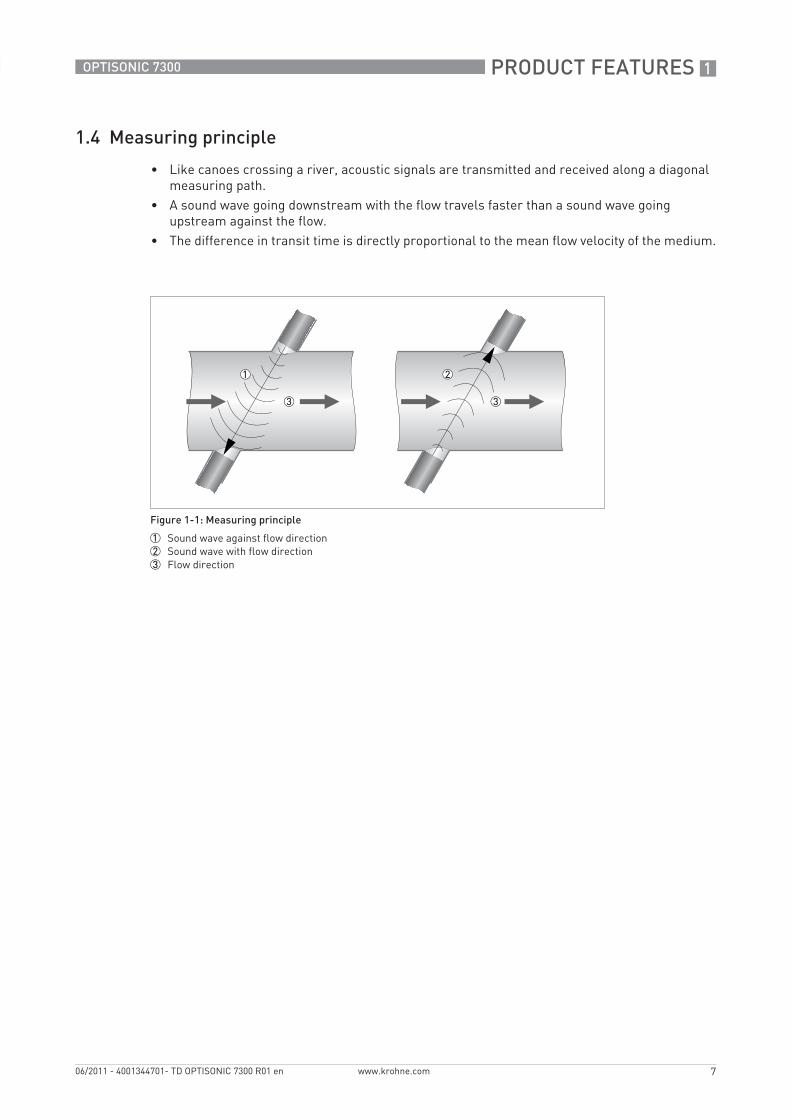
1.4 Measuring principle
• Like canoes crossing a river, acoustic signals are transmitted and received along a diagonal measuring path.
• A sound wave going downstream with the flow travels faster than a sound wave going upstream against the flow.
• The difference in transit time is directly proportional to the mean flow velocity of the medium.
Figure 1-1: Measuring principle
1 Sound wave against flow direction2 Sound wave with flow direction3 Flow direction
2 TECHNICAL DATA
8
OPTISONIC 7300
www.krohne.com 06/2011 - 4001344701- TD OPTISONIC 7300 R01 en
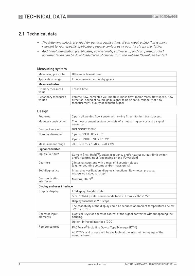
2.1 Technical data
• The following data is provided for general applications. If you require data that is more relevant to your specific application, please contact us or your local representative.
• Additional information (certificates, special tools, software,...) and complete product documentation can be downloaded free of charge from the website (Download Center).
Measuring systemMeasuring principle Ultrasonic transit time
Application range Flow measurement of dry gases
Measured valueMeasured valueMeasured valueMeasured value
Primary measured value
Transit time
Secondary measured values
Volume flow, corrected volume flow, mass flow, molar mass, flow speed, flow direction, speed of sound, gain, signal to noise ratio, reliability of flow measurement, quality of acoustic signal
DesignFeatures 2 path all welded flow sensor with o-ring fitted titanium transducers.
Modular construction The measurement system consists of a measuring sensor and a signal converter.
Compact version OPTISONIC 7300 C
Nominal diameter 1 path: DN50...80 / 2...3"
2 path: DN100...600 / 4"...24"
Measurement range -30... +30 m/s / -98.4... +98.4 ft/s
Signal converterSignal converterSignal converterSignal converter
Inputs / outputs Current (incl. HART®), pulse, frequency and/or status output, limit switch and/or control input (depending on the I/O version)
Counters 2 internal counters with a max. of 8 counter places (e.g. for counting volume and/or mass units).
Self diagnostics Integrated verification, diagnosis functions: flowmeter, process, measured value, bargraph
Communication interfaces
Modbus, HART®
Display and user interfaceDisplay and user interfaceDisplay and user interfaceDisplay and user interface
Graphic display LC display, backlit white
Size: 128x64 pixels, corresponds to 59x31 mm = 2.32"x1.22"
Display turnable in 90° steps.
The readability of the display could be reduced at ambient temperatures below -25°C / -13°F.
Operator input elements
4 optical keys for operator control of the signal converter without opening the housing.
Option: Infrared interface (GDC)
Remote control PACTware® including Device Type Manager (DTM)
All DTM's and drivers will be available at the internet homepage of the manufacturer.

TECHNICAL DATA 2
9
OPTISONIC 7300
www.krohne.com06/2011 - 4001344701- TD OPTISONIC 7300 R01 en
Display functionsDisplay functionsDisplay functionsDisplay functions
Menu Programming of parameters at 2 measured value pages, 1 status page, 1 graphic page (measured values and descriptions adjustable as required)
Language of display texts
English, French, German
Units Metric, British and US units selectable from list / free unit.
Measuring accuracyGas flow (uncorrected)Gas flow (uncorrected)Gas flow (uncorrected)Gas flow (uncorrected)
Reference conditions (for gas calibration)
Medium: Air
Temperature: 20°C / 68°F
Pressure: 1 Bar / 14.5 psig
Theoretical calibration (standard)
DN100..600 / 4…24": < ± 2% of actual measured flow rate, for 1...30 m/s
DN50..80 / 2…3": < ± 3% of actual measured flow rate, for 1...30 m/s
Gas calibration DN100..600 / 4…24": < ± 1% of actual measured flow rate, for 1...30 m/s
DN50..80 / 2…3": < ± 2% of actual measured flow rate, for 1...30 m/s
Repeatability < ± 0.2%
Operating conditionsTemperatureTemperatureTemperatureTemperature
Process temperature -40..+125°C / -40..+257°F
Carbon steel flanges acc. to EN 1092-1, min. process temperature: -10°C / +14°F
Carbon steel flanges acc. to ASME, min. process temperature: -29°C / -20°F
Higher process temperatures on request.
Ambient temperature Standard (die-cast aluminum converter housing): -40…+65°C / -40…+149°F
Optional (die-cast stainless steel converter housing): -40... +55°C / -40...+131°F
Storage temperature -50…+70°C / -58…+158°F
PressurePressurePressurePressure
EN 1092-1 DN200…600: PN 10
DN100…150: PN 16
DN50...80: PN 40
ASME B16.5 2…24”: 150 lb RF
2…24”: 300 lb RF
2…24”: 600 lb RF
2...14": 900 lb RF

2 TECHNICAL DATA
10
OPTISONIC 7300
www.krohne.com 06/2011 - 4001344701- TD OPTISONIC 7300 R01 en
Properties of mediumProperties of mediumProperties of mediumProperties of medium (Other properties on request)
Physical condition Dry gas
Density Standard: 15…45 g/mol
Option: 5…75 g/mol
Velocity of sound 250…600 m/s
Installation conditionsInstallation For detailed information refer to Installation on page 22.
Inlet run ≥ 10 DN
Outlet run ≥ 3 DN
Dimensions and weights
For detailed information refer to Dimensions and weights on page 18.
MaterialsSensorSensorSensorSensor
Flanges (wetted)
Standard: Carbon steel ASTM A105 N
Option: Stainless steel 316 L, Carbon steel A350 LF2
Other materials on request.
Tube (wetted)
Standard: Carbon steel ASTM A106 Gr. B or Equivalent
Option: Stainless steel 316 L, Carbon steel A333 GR6
Other materials on request.
Nozzles transducer holders (wetted)
Stainless steel 316 Ti (1.4571)
Transducer holders (wetted)
Stainless steel 316 L (1.4404)
Transducers (wetted) Titanium grade 29
O-rings (wetted) FKM / FPM
Coating Polyurethane
Tube transducer cabling, caps transducer holder
Stainless steel 316 L
Converter/ connection-box support:
Stainless steel
ConverterConverterConverterConverter
Converter housing Standard: Die-cast aluminium, polyurethane coated
Option: Stainless steel 316 (1.4408)
Electrical connectionsPower supply StandardStandardStandardStandard
100…230 VAC (-15% / +10%), 50/60 Hz
OptionOptionOptionOption
24 VAC/DC (AC: -15% / +10%; DC: -25% / +30%)
Power consumption AC: 22 VA
DC: 12 W
Cable entries Standard: M20 x 1.5
Option: ½" NPT, PF ½

TECHNICAL DATA 2
11
OPTISONIC 7300
www.krohne.com06/2011 - 4001344701- TD OPTISONIC 7300 R01 en
Inputs and outputsGeneral All in-and outputs are galvanically isolated from each other and from all other
circuits.
Description of used abbreviations
Uext = external voltage Unom = nominal voltageUint = internal voltageUo = terminal voltageRL = resistance of loadInom = nominal current
Current outputCurrent outputCurrent outputCurrent output
Output data Measurement of volume and mass (at constant density), HART® communication.
Settings Without HARTWithout HARTWithout HARTWithout HART®
Q = 0%: 0…15 mA
Q = 100%: 10…20 mA
Error identification: 3…22 mA
With HARTWith HARTWith HARTWith HART®
Q = 0%: 4…15 mA
Q = 100%: 10…20 mA
Error identification: 3…22 mA
Operating data Basic I/OsBasic I/OsBasic I/OsBasic I/Os Modular I/OsModular I/OsModular I/OsModular I/Os Ex-iEx-iEx-iEx-i
Active Uint = 24 VDC
I ≤ 22 mA
RL ≤ 1 kΩ
Uint = 20 VDC
I ≤ 22 mA
RL ≤ 450 Ω
U0 = 21 V I0 = 90 mA P0 = 0.5 W C0 = 90 nF / L0 = 2 mH C0 = 110 nF / L0 = 0.5 mH
Passive Uext ≤ 32 VDC
I ≤ 22 mA
U0 ≥ 1.8 V
RL≤ (Uext - Uo) / Imax
Uext ≤ 32 VDC
I ≤ 22 mA
U0 ≥ 4 V
RL≤ (Uext - Uo) / Imax
UI = 30 V II = 100 mA PI = 1 W CI = 10 nF LI = 0 mH
2 TECHNICAL DATA
12
OPTISONIC 7300
www.krohne.com 06/2011 - 4001344701- TD OPTISONIC 7300 R01 en
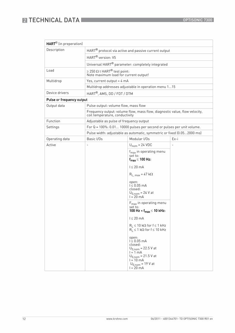
HARTHARTHARTHART® (in preperation)
Description HART® protocol via active and passive current output
HART® version: V5
Universal HART® parameter: completely integrated
Load ≥ 250 Ω t HART® test point: Note maximum load for current output!
Multidrop Yes, current output = 4 mA
Multidrop addresses adjustable in operation menu 1...15
Device drivers HART®, AMS, DD / FDT / DTM
Pulse or frequency outputPulse or frequency outputPulse or frequency outputPulse or frequency output
Output data Pulse output: volume flow, mass flow
Frequency output: volume flow, mass flow, diagnostic value, flow velocity, coil temperature, conductivity
Function Adjustable as pulse of frequency output
Settings For Q = 100%: 0.01... 10000 pulses per second or pulses per unit volume.
Pulse width: adjustable as automatic, symmetric or fixed (0.05...2000 ms)
Operating data Basic I/Os Modular I/Os Ex-i
Active - Unom = 24 VDC -
fmax in operating menu set to: ffffmaxmaxmaxmax ≤ 100 Hz: 100 Hz: 100 Hz: 100 Hz:
I ≤ 20 mA
RL, max = 47 kΩ
open:I ≤ 0.05 mA closed: U0,nom = 24 V at I = 20 mA
Fmax in operating menu set to: 100 Hz < f100 Hz < f100 Hz < f100 Hz < fmaxmaxmaxmax ≤ 10 kHz: 10 kHz: 10 kHz: 10 kHz:
I ≤ 20 mA
RL ≤ 10 kΩ for f ≤ 1 kHzRL ≤ 1 kΩ for f ≤ 10 kHz
open: I ≤ 0.05 mA closed: U0,nom = 22.5 V at I = 1 mA U0,nom = 21.5 V at I = 10 mA U0,nom = 19 V at I = 20 mA

TECHNICAL DATA 2
13
OPTISONIC 7300
www.krohne.com06/2011 - 4001344701- TD OPTISONIC 7300 R01 en
Passive Uext ≤ 32 VDC -
fmax in operating menu set to: ffffmaxmaxmaxmax ≤ 100 Hz: 100 Hz: 100 Hz: 100 Hz:
I ≤ 100 mA
RL, max = 47 kΩRL, max = (Uext - U0) / Imax
open: I ≤ 0.05 mA at Uext = 32 VDC closed: U0, max = 0.2 V at I ≤ 10 mA U0, max = 2 V at I ≤ 100 mA
fmax in operating menu set to:100 Hz < f100 Hz < f100 Hz < f100 Hz < fmaxmaxmaxmax ≤ 10 kHz: 10 kHz: 10 kHz: 10 kHz:
I ≤ 20 mA
RL ≤ 10 kΩ for f ≤ 1 kHzRL ≤ 1 kΩ for f ≤ 10 kHzRL, max = (Uext - U0) / Imax
open: I ≤ 0.05 mA at Uext = 32 VDC closed: U0, max = 1.5 V at I ≤ 1mA U0, max = 2.5 V at I ≤ 10 mA U0, max = 5.0 V at I ≤ 20 mA
NAMUR - Passive to EN 60947-5-6
open: Inom = 0.6 mA closed: Inom = 3.8 mA
Passive to EN 60947-5-6
open: Inom = 0.43 mA closed: Inom = 4.5 mA
UI = 30 V II = 100 mA PI = 1 W CI = 10 nF LI = 0 mH
2 TECHNICAL DATA
14
OPTISONIC 7300
www.krohne.com 06/2011 - 4001344701- TD OPTISONIC 7300 R01 en
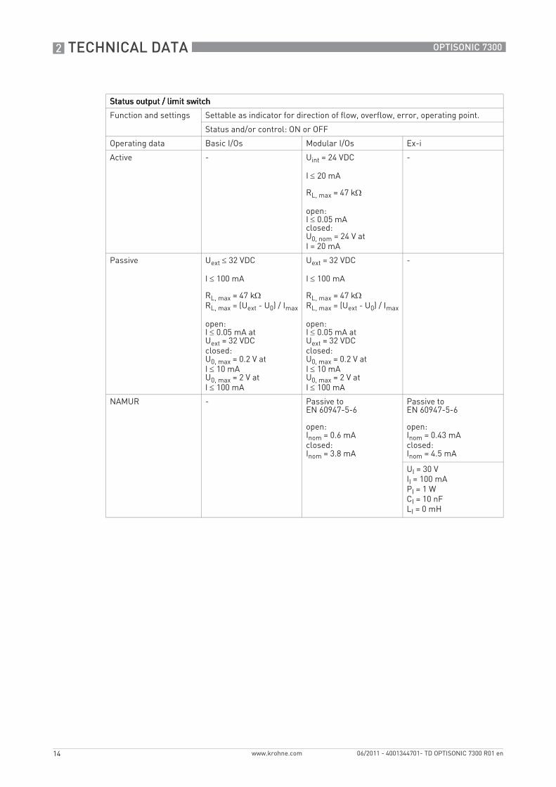
Status output / limit switchStatus output / limit switchStatus output / limit switchStatus output / limit switch
Function and settings Settable as indicator for direction of flow, overflow, error, operating point.
Status and/or control: ON or OFF
Operating data Basic I/Os Modular I/Os Ex-i
Active - Uint = 24 VDC
I ≤ 20 mA
RL, max = 47 kΩ
open: I ≤ 0.05 mA closed: U0, nom = 24 V at I = 20 mA
-
Passive Uext ≤ 32 VDC
I ≤ 100 mA
RL, max = 47 kΩ RL, max = (Uext - U0) / Imax
open: I ≤ 0.05 mA at Uext = 32 VDC closed: U0, max = 0.2 V at I ≤ 10 mA U0, max = 2 V at I ≤ 100 mA
Uext = 32 VDC
I ≤ 100 mA
RL, max = 47 kΩ RL, max = (Uext - U0) / Imax
open: I ≤ 0.05 mA at Uext = 32 VDC closed: U0, max = 0.2 V at I ≤ 10 mA U0, max = 2 V at I ≤ 100 mA
-
NAMUR - Passive to EN 60947-5-6
open: Inom = 0.6 mA closed: Inom = 3.8 mA
Passive to EN 60947-5-6
open: Inom = 0.43 mA closed: Inom = 4.5 mA
UI = 30 V II = 100 mA PI = 1 W CI = 10 nF LI = 0 mH

TECHNICAL DATA 2
15
OPTISONIC 7300
www.krohne.com06/2011 - 4001344701- TD OPTISONIC 7300 R01 en
Control inputControl inputControl inputControl input
Function Set value of the outputs to "zero", counter and error reset, range change.
Operating data Basic I/Os Modular I/Os Ex-i
Active - Uint = 24 VDC
Terminals open: U0, nom = 22 V
Terminals bridged: Inom = 4 mA
On: U0 ≥ 12 V with Inom = 1.9 mA
Off: U0 ≤ 10 V with Inom = 1.9 mA
-
Passive Uext ≤ 32 VDC
Imax = 6.5 mA at Uext ≤ 24 VDC
Imax = 8.2 mA at Uext ≤ 32 VDC
Contact closed (On): U0 ≥ 8 V with Inom = 2.8 mA
Contact open (Off): U0 ≤ 2.5 V with Inom = 0.4 mA
Uext ≤ 32 VDC
Imax = 9.5 mA at Uext ≤ 24 V
Imax = 9.5 mA at Uext ≤ 32 V
Contact closed (On): U0 ≥ 3 V with Inom = 1.9 mA
Contact open (Off): U0 ≤ 2.5 V with Inom = 1.9 mA
Uext ≤ 32 VDC
I ≤ 6 mA at Uext = 24 V I ≤ 6.6 mA at Uext = 32 V
On: U0 ≥ 5.5 V or I ≥ 4mA Off: U0 ≤ 3.5 V or I ≤ 0.5 mA
UI = 30 V II = 100 mA PI = 1 W CI = 10 nF LI = 0 mH
NAMUR - Active to EN 60947-5-6
Contact open: U0, nom = 8.7 V
Contact closed (On): Inom = 7.8 mA
Contact open (off): U0, nom = 6.3 V with Inom = 1.9 mA
Identification for open terminals: U0 ≥ 8.1 V with I ≤ 0.1 mA
Dentification for short circuited terminals: U0 ≤ 1.2 V with I ≥ 6.7 mA
-

2 TECHNICAL DATA
16
OPTISONIC 7300
www.krohne.com 06/2011 - 4001344701- TD OPTISONIC 7300 R01 en
Low-flow cutoffLow-flow cutoffLow-flow cutoffLow-flow cutoff
On 0...±9.999 m/s; 0...20.0%, settable in 0.1% steps, separately for each current and pulse output.
Off 0...±9.999 m/s; 0...19.0%, settable in 0.1% steps, separately for each current and pulse output.
Time constantTime constantTime constantTime constant
Function Can be set together for all flow indicators and outputs, or separately for: current, pulse and frequency output, limit switches and the 3 internal counters.
Time setting 0…100 seconds, settable in 0.1 second steps.
Current inputCurrent inputCurrent inputCurrent input
Function For conversion to standard conditions, input from external temperature and pressure transmitters is required.
Operating data Basic I/Os Modular I/Os Ex i
Active - Uint = 24 VDC
I ≤ 22 mA
Imax ≤ 26 mA(electronically limited)
U0, min = 19 V at I ≤ 22 mA
Uint = 20 VDC
I ≤ 22 mA
U0, min = 14 V at I ≤ 22 mA
No HART®
No HART® U0 = 24.1 V I0 = 99 mA P0 = 0.6 W C0 = 75 nF / L0 = 0.5 mH
No HART®
Passive - Uext ≤ 32 VDC
I ≤ 22 mA
Imax ≤ 26 mA (electronically limited)
U0, max = 5 V at I ≤ 22 mA
Uext ≤ 32 VDC
I ≤ 22 mA
U0, max = 4 V at I ≤ 22 mA
No HART®
No HART® UI = 30 V II = 100 mA PI = 1 W CI = 10 nF LI =0 mH
No HART®

TECHNICAL DATA 2
17
OPTISONIC 7300
www.krohne.com06/2011 - 4001344701- TD OPTISONIC 7300 R01 en
MODBUSMODBUSMODBUSMODBUS (in preparation)
Description Modbus RTU, Master / Slave, RS485
Address range 1…247
Supported function codes
03, 04, 16
Broadcast Supported with function code 16
Supported Baudrate 1200, 2400, 4800, 9600, 19200, 38400, 57600, 115200 Baud
Approvals and certificatesCECECECE
This device fulfills the statutory requirements of the EC directives. The manufacturer certifies successful testing of the product by applying the CE mark.
Electromagnetic compatibility
Directive: 2004/108/EC, NAMUR NE21/04
Harmonized standard: EN 61326-1 : 2006
Low Voltage Directive Directive: 2006/95/EC
Harmonized standard: EN 61010 : 2001
Pressure equipment directive
Directive: 97/23/EC
Category I, II, III or SEP
Fluid group 1
Production module H
Other approvals and standardsOther approvals and standardsOther approvals and standardsOther approvals and standards
Non-Ex Standard
Hazardous areasHazardous areasHazardous areasHazardous areas
Please check the relevant ex documentation for details.
ATEX PTB 10 ATEX 1052
Protection category acc. to IEC 529 / EN 60529
Signal converterSignal converterSignal converterSignal converter
Compact (C): IP 66/67 (NEMA 4X/6)
All sensorsAll sensorsAll sensorsAll sensors
IP 67 (NEMA 6)
Vibration resistance IEC 68-2-64
Shock resistance IEC 68-2-27

2 TECHNICAL DATA
18
OPTISONIC 7300
www.krohne.com 06/2011 - 4001344701- TD OPTISONIC 7300 R01 en
2.2 Dimensions and weights
2.2.1 Gas flow sensor, carbon steel
EN 1092-1
Compact versionCompact versionCompact versionCompact version a = 155 mm / 6.1"
b = 230 mm / 9.1" 1
c = 260 mm / 10.2"
Total height = H + a
1 The value may vary depending on the used cable glands.
Nominal size Dimensions [mm] Approx weight
[kg]DN PN [Bar] L H W Di
200 PN 10 460 368 429 202.7 46
250 PN 10 530 423 474 254.5 66
300 PN 10 580 473 517 304.8 81
350 PN 10 610 519 542 333.4 109
400 PN 10 640 575 583 381.0 141
450 PN 10 620 625 623 427.0 170
500 PN 10 670 678 670 478.0 202
600 PN 10 790 784 780 579.6 278
Nominal size Dimensions [mm] Approx weight
[kg]DN PN [Bar] L H W Di
100 PN 16 490 254 337 97.1 24
125 PN 16 520 283 359 122.3 32
150 PN 16 540 315 387 154.1 35

TECHNICAL DATA 2
19
OPTISONIC 7300
www.krohne.com06/2011 - 4001344701- TD OPTISONIC 7300 R01 en
ASME 150 lb
ASME 300 lb
Nominal size Dimensions [mm] Approx weight
[kg]DN PN [Bar] L H W Di
50 PN 40 320 196 300 49.3 11
65 PN 40 350 216 313 62.1 14
80 PN 40 480 230 324 73.7 19
Nominal size Dimensions [inches] Approx weight
[lb]L H W Di
2" 14.2 7.5 11.8 1.9 22
2½" 15.0 8.3 12.2 2.3 33
3" 20.5 8.9 12.8 2.9 44
4" 21.7 10.1 13.3 3.8 64
5" 23.2 11.2 14.1 4.8 84
6" 24.4 12.2 15.2 6.1 90
8" 21.2 14.5 16.9 8.0 130
10" 24.0 16.9 18.7 10.0 185
12" 26.4 19.4 20.4 12.0 266
14" 28.7 21.0 21.3 13.1 352
16" 30.3 23.3 23.5 15.0 462
18" 30.7 25.0 25.0 16.8 570
20" 32.7 27.3 27.5 18.8 607
24" 35.8 31.5 32.0 22.8 904
Nominal size Dimensions [inches] Approx weight
[lb]L H W Di
2" 15.0 7.7 11.8 1.9 27
2½" 15.4 8.5 12.2 2.3 38
3" 21.3 9.3 12.8 2.9 53
4" 22.4 10.7 13.3 3.8 86
5" 24.0 11.7 14.1 4.8 115
6" 25.2 13.0 5.0 5.8 146
8" 22.0 15.3 16.6 7.6 207
10" 25.2 17.6 18.3 9.6 309
12" 28.0 20.1 20.5 11.4 452
14" 29.9 22.0 23.0 12.5 609
16" 31.9 24.3 25.5 14.3 785
18" 33.1 26.5 28.0 16.4 926
20" 36.6 28.8 30.5 18.0 1237
24" 38.2 33.5 36.0 22.0 1715

2 TECHNICAL DATA
20
OPTISONIC 7300
www.krohne.com 06/2011 - 4001344701- TD OPTISONIC 7300 R01 en
ASME 600 lb
ASME 900 lb
Nominal size Dimensions [inches] Approx weight
[lb]L H W Di
2" 15.7 7.7 11.5 1.7 33
2½" 16.1 8.5 12.0 2.1 44
3" 22.0 9.3 12.5 2.6 66
4" 24.4 11.1 13.1 3.6 119
5" 26.0 12.7 14.1 4.8 183
6" 27.2 13.8 15.0 5.8 223
8" 24.4 16.1 16.5 7.4 333
10" 27.2 18.3 20.0 9.3 531
12" 28.3 20.9 22.0 11.2 655
14" 29.9 22.4 23.7 12.1 798
16" 32.7 25.0 27.0 14.0 1105
18" 34.6 27.1 29.3 15.6 1389
20" 35.4 29.5 32.0 17.6 1695
24" 38.2 34.0 37.0 21.2 2438
Nominal size Dimensions [inches] Approx weight
[lb]L H W Di
2" 17.7 8.7 11.5 1.7 64
2½" 18.1 9.6 12.0 2.1 86
3" 23.6 9.9 12.5 2.6 119
4" 26.8 11.4 13.0 3.4 157
5" 26.8 12.6 13.7 3.2 240
6" 28.7 14.3 15.0 5.2 335
8" 26.8 17.0 18.5 6.8 545
10" 29.9 19.6 21.5 8.5 838
12" 31.9 21.9 24.0 10.1 1168
14" 33.9 23.1 25.2 11.2 1382
TECHNICAL DATA 2
21
OPTISONIC 7300
www.krohne.com06/2011 - 4001344701- TD OPTISONIC 7300 R01 en
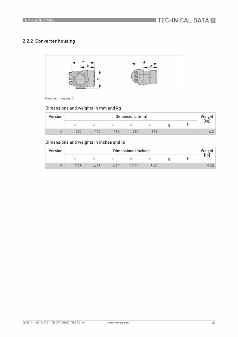
2.2.2 Converter housing
Dimensions and weights in mm and kg
Dimensions and weights in inches and lb
Compact housing (C)
Version Dimensions [mm] Weight [kg]
a b c d e g h
C 202 120 155 260 137 - - 4.2
Version Dimensions [inches] Weight [lb]
a b c d e g h
C 7.75 4.75 6.10 10.20 5.40 - - 9.30

3 INSTALLATION
22
OPTISONIC 7300
www.krohne.com 06/2011 - 4001344701- TD OPTISONIC 7300 R01 en
3.1 Intended use
The overall functionality of the ultrasonic gas flowmeter is the continuous measurement of actual volume flow, mass flow, flow speed, velocity of sound, gain, SNR and diagnosis value.
3.2 Environmental requirements
• Humidity: 5...80 % RH• Ambient temperature: -40…+65°C / -40…+148°F • Storage temperature: -50…+70°C / -58…+158°F• Suitable for indoor and outdoor use and certified for operating up to an altitude of
2000 m / 6562 ft• IP class 66/67
3.3 Installation requirements signal converter
• Allow 10…20 cm / 3.9…7.9" of space at the sides and rear of the signal converter to permit free air circulation.
• Protect signal converter against direct solar radiation, install a sunshield if necessary.• Signal converters installed in switchgear cabinets require adequate cooling, e.g. by fan or
heat exchanger.• Do not expose the signal converter to intense vibration.
3.4 Installation requirements sensor
To secure the optimum functioning of the flowmeter, please note the following observations.
The OPTISONIC 7300 is in principle designed for the measurement of dry gas flow. The collection of liquid in the transducers can interrupt the acoustic signals and should thus be avoided.The following guidelines should be observed in case occasional small amounts of liquids are to be expected:
• Install the flowsensor in a horizontal position in a slightly descending line.• Orientate the flowsensor such that the path of the acoustic signal is in the horizontal plane.
For exchanging the transducers, please keep a free space of 1 m / 39" around the transducer.

INSTALLATION 3
23
OPTISONIC 7300
www.krohne.com06/2011 - 4001344701- TD OPTISONIC 7300 R01 en
3.4.1 Inlet and outlet
3.4.2 Vertical mounting
3.4.3 Mounting position
Figure 3-1: Recommended inlet and outlet
1 ≥ 10 DN2 ≥ 3 DN
Figure 3-2: Vertical mounting
Vertical mounting onlyonlyonlyonly with dry gas. Never mount vertically with risk on condensation or wet gas.
Figure 3-3: Mounting position

3 INSTALLATION
24
OPTISONIC 7300
www.krohne.com 06/2011 - 4001344701- TD OPTISONIC 7300 R01 en
3.4.4 Vibration
3.4.5 Control valve
To avoid distorted flowprofiles and interference caused by valve noise in the sensor, control valves or pressure reducers should not be installed in the same pipeline as the flowmeter. In case this is required, please contact the manufacturer.
Figure 3-4: Avoid vibrations
Figure 3-5: Control valve

INSTALLATION 3
25
OPTISONIC 7300
www.krohne.com06/2011 - 4001344701- TD OPTISONIC 7300 R01 en
3.4.6 Flange deviation
3.4.7 T-section
Max. permissible deviation of pipe flange faces: Lmax - Lmin ≤ 0.5 mm / 0.02"
Figure 3-6: Flange deviation
1 Lmax2 Lmin
Figure 3-7: Distance after T-sections
1 ≥ 10 DN

4 ELECTRICAL CONNECTIONS
26
OPTISONIC 7300
www.krohne.com 06/2011 - 4001344701- TD OPTISONIC 7300 R01 en
4.1 Safety instructions
4.2 Power supply
100…230 VAC• Connect the protective ground conductor PE of the mains power supply to the separate
terminal in the terminal compartment of the signal converter.• Connect the live conductor to the L terminal and the neutral conductor to the N terminal.
24 VAC/DC• Connect a functional ground FE to the separate U-clamp terminal in the terminal
compartment of the signal converter.• When connecting to functional extra-low voltages, provide a facility for protective separation
(PELV) (VDE 0100 / VDE 0106 and/or IEC 364 / IEC 536 or relevant national regulations).
All work on the electrical connections may only be carried out with the power disconnected. Take note of the voltage data on the nameplate!
Observe the national regulations for electrical installations!
For devices used in hazardous areas, additional safety notes apply; please refer to the Ex documentation.
Observe without fail the local occupational health and safety regulations. Any work done on the electrical components of the measuring device may only be carried out by properly trained specialists.
Look at the device nameplate to ensure that the device is delivered according to your order. Check for the correct supply voltage printed on the nameplate.
The power terminals in the terminal compartments are equipped with additional hinged lids to prevent accidental contact.
1 100...230 VAC (-15% / +10%), 22 VA2 24 VAC/DC (AC: -15% / +10%; DC: -25% / +30%), 22 VA or 12 W
The device must be grounded in accordance with regulations in order to protect personnel against electric shocks.

ELECTRICAL CONNECTIONS 4
27
OPTISONIC 7300
www.krohne.com06/2011 - 4001344701- TD OPTISONIC 7300 R01 en
4.3 Inputs and outputs, overview
4.3.1 Combinations of the inputs/outputs (I/Os)
This signal converter is available with various input/output combinations.
Basic version• Has 1 current output, 1 pulse output and 2 status outputs / limit switches.• The pulse output can be set as status output/limit switch and one of the status outputs as a
control input.
Ex i version• Depending on the task, the device can be configured with various output modules.• Current outputs can be active or passive.• Optionally available also with Foundation Fieldbus and Profibus PA
Modular version• Depending on the task, the device can be configured with various output modules.
Bus systems• The device allows intrinsically safe and non intrinsically safe bus interfaces in combination
with additional modules.• For connection and operation of bus systems, please note the separate documentation.
Ex option• For hazardous areas, all of the input/output variants for the housing designs with terminal
compartment in the Ex d (pressure-resistant casing) or Ex e (increased safety) versions can be delivered.
• Please refer to the separate instructions for connection and operation of the Ex-devices.

4 ELECTRICAL CONNECTIONS
28
OPTISONIC 7300
www.krohne.com 06/2011 - 4001344701- TD OPTISONIC 7300 R01 en
4.3.2 Description of the CG number
The last 3 digits of the CG number (5, 6 and 7) indicate the assignment of the terminal connections. Please see the following examples.
Examples for CG number
Description of abbreviations and CG identifier for possible optional moduleson terminals A and B
Figure 4-1: Marking (CG number) of the electronics module and input/output variants
1 ID number: 62 ID number: 0 = standard3 Power supply option4 Display (language versions)5 Input/output version (I/O)6 1st optional module for connection terminal A7 2nd optional module for connection terminal B
CG 360 11 100 100...230 VAC & standard display; basic I/O: Ia or Ip & Sp/Cp & Sp & Pp/Sp
CG 360 11 7FK 100...230 VAC & standard display; modular I/O: Ia & PN/SN and optional module PN/SN & CN
CG 360 81 4EB 24 VDC & standard display; modular I/O: Ia & Pa/Sa and optional module Pp/Sp & Ip
Abbreviation Identifier for CG No. Description
Ia A Active current output
Ip B Passive current output
Pa / Sa C Active pulse, frequency, status output or limit switch (changeable)
Pp / Sp E Passive pulse, frequency, status output or limit switch (changeable)
PN / SN F Passive pulse, frequency, status output or limit switch according to NAMUR (changeable)
Ca G Active control input
Cp K Passive control input
CN H Active control input to NAMURSignal converter monitors cable breaks and short circuits acc. to EN 60947-5-6. Errors indicated on LC display. Error messages possible via status output.
IIna P Active current input
IInp R Passive current input
- 8 No additional module installed
- 0 No further module possible

ELECTRICAL CONNECTIONS 4
29
OPTISONIC 7300
www.krohne.com06/2011 - 4001344701- TD OPTISONIC 7300 R01 en
4.3.3 Fixed, non-alterable input/output versions
This signal converter is available with various input/output combinations.
• The grey boxes in the tables denote unassigned or unused connection terminals.• In the table, only the final digits of the CG no. are depicted.• Connection terminal A+ is only operable in the basic input/output version.
CG-No. Connection terminals
A+ A A- B B- C C- D D-
Basic in-/output (I/O) (Standard)1 0 0 Ip + HART® passive 1 Sp / Cp passive 2 Sp passive Pp / Sp passive 2
Ia + HART® active 1
Ex-i in-/outputs (Option)2 0 0 Ia + HART® active PN / SN NAMUR 2
3 0 0 Ip + HART® passive PN / SN NAMUR 2
2 1 0 Ia active PN / SN NAMURCp passive 2
Ia + HART® active PN / SN NAMUR 2
3 1 0 Ia active PN / SN NAMURCp passive 2
Ip + HART® passive PN / SN NAMUR 2
2 2 0 Ip passive PN / SN NAMURCp passive 2
Ia + HART® active PN / SN NAMUR 2
3 2 0 Ip passive PN / SN NAMURCp passive 2
Ip + HART® passive PN / SN NAMUR 2
1 Function changed by reconnecting2 Changeable

4 ELECTRICAL CONNECTIONS
30
OPTISONIC 7300
www.krohne.com 06/2011 - 4001344701- TD OPTISONIC 7300 R01 en
4.3.4 Alterable input/output versions
This signal converter is available with various input/output combinations.
• The grey boxes in the tables denote unassigned or unused connection terminals.• In the table, only the final digits of the CG no. are depicted.• Term. = (connection) terminal
CG no.
Connection terminals
A+ A A- B B- C C- D D-
Modular IOs (option)4 _ _ max. 2 optional modules for term. A + B Ia + HART® active Pa / Sa active 1
8 _ _ max. 2 optional modules for term. A + B Ip + HART® passive Pa / Sa active 1
6 _ _ max. 2 optional modules for term. A + B Ia + HART® active Pp / Sp passive 1
B _ _ max. 2 optional modules for term. A + B Ip + HART® passive Pp / Sp passive 1
7 _ _ max. 2 optional modules for term. A + B Ia + HART® active PN / SN NAMUR 1
C _ _ max. 2 optional modules for term. A + B Ip + HART® passive PN / SN NAMUR 1
Modbus (Option)G _ _ 2 max. 2 optional modules for term. A + B Common Sign. B
(D1)Sign. A (D0)
H _ _ 3 max. 2 optional modules for term. A + B Common Sign. B (D1)
Sign. A (D0)
1 Changeable2 Not activated bus terminator 3 Activated bus terminator

APPLICATION FORM 5
31
OPTISONIC 7300
www.krohne.com06/2011 - 4001344701- TD OPTISONIC 7300 R01 en
Please fill in this form and fax or email it to your local representive. Please include a sketch of the pipe layout as well, including the X, Y, Z dimensions.
Customer information:Date:
Submitted by:
Company:
Address:
Telephone:
Fax:
E-mail:
Flow application data:Reference information (name, tag etc):
New applicationExisting application, currently using:
Measurement objective:
MediumMediumMediumMedium
Gas composition:
CO2 content:
H2 content:
Density:
Velocity of sound:
FlowrateFlowrateFlowrateFlowrate
Normal:
Minimum:
Maximum:
TemperatureTemperatureTemperatureTemperature
Normal:
Minimum:
Maximum:
PressurePressurePressurePressure
Normal:
Minimum:
Maximum:
5 APPLICATION FORM
32
OPTISONIC 7300
www.krohne.com 06/2011 - 4001344701- TD OPTISONIC 7300 R01 en
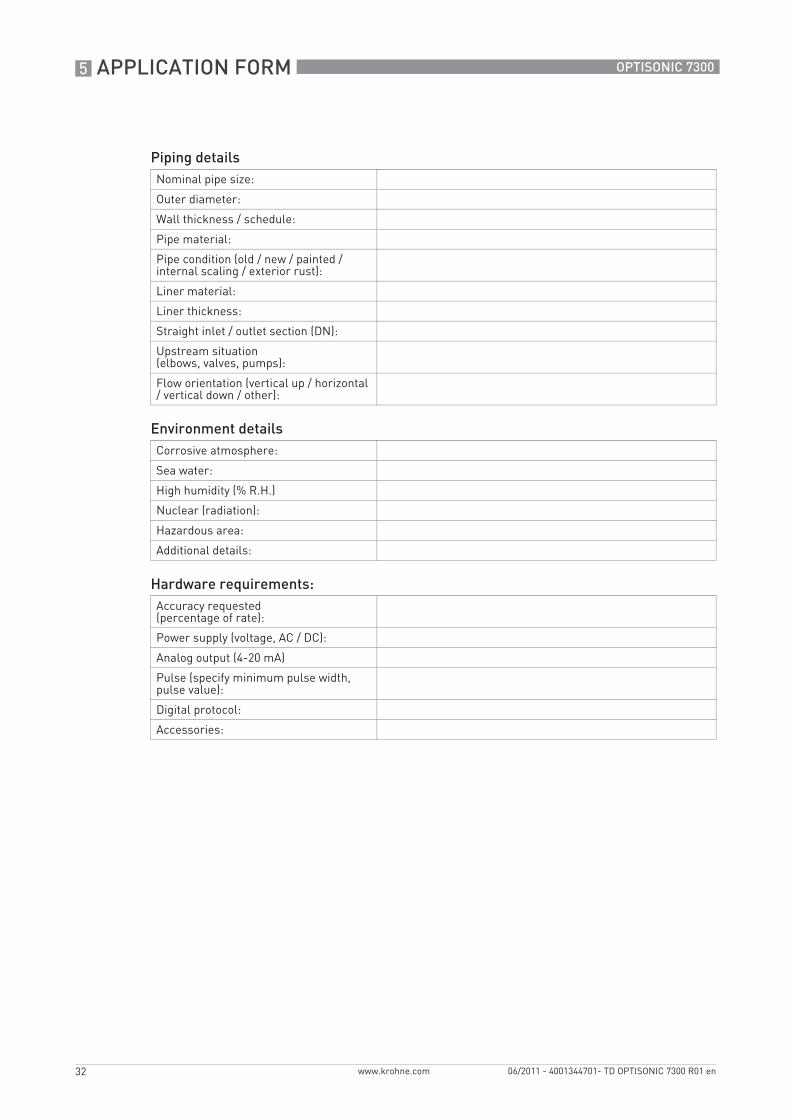
Piping detailsNominal pipe size:
Outer diameter:
Wall thickness / schedule:
Pipe material:
Pipe condition (old / new / painted / internal scaling / exterior rust):
Liner material:
Liner thickness:
Straight inlet / outlet section (DN):
Upstream situation (elbows, valves, pumps):
Flow orientation (vertical up / horizontal / vertical down / other):
Environment detailsCorrosive atmosphere:
Sea water:
High humidity (% R.H.)
Nuclear (radiation):
Hazardous area:
Additional details:
Hardware requirements:Accuracy requested (percentage of rate):
Power supply (voltage, AC / DC):
Analog output (4-20 mA)
Pulse (specify minimum pulse width, pulse value):
Digital protocol:
Accessories:

NOTES 6
33
OPTISONIC 7300
www.krohne.com06/2011 - 4001344701- TD OPTISONIC 7300 R01 en

6 NOTES
34
OPTISONIC 7300
www.krohne.com 06/2011 - 4001344701- TD OPTISONIC 7300 R01 en

NOTES 6
35
OPTISONIC 7300
www.krohne.com06/2011 - 4001344701- TD OPTISONIC 7300 R01 en

KROHNE product overview
• Electromagnetic flowmeters
• Variable area flowmeters
• Ultrasonic flowmeters
• Mass flowmeters
• Vortex flowmeters
• Flow controllers
• Level meters
• Temperature meters
• Pressure meters
• Analysis products
• Measuring systems for the oil and gas industry
• Measuring systems for sea-going tankers
Head Office KROHNE Messtechnik GmbHLudwig-Krohne-Str. 5D-47058 Duisburg (Germany)Tel.:+49 (0)203 301 0Fax:+49 (0)203 301 10389 [email protected]
© K
RO
HN
E 06
/201
1 -
4001
3447
01-
TD O
PTI
SON
IC 7
300
R01
en
- Su
bjec
t to
chan
ge w
ithou
t not
ice.
The current list of all KROHNE contacts and addresses can be found at:www.krohne.com
KK
K