opto-electronic tracking system · • manual and auto wni dow szini g • selectable poal rity...
TRANSCRIPT
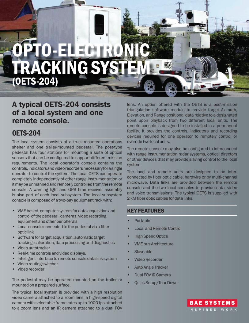
The local system consists of a truck-mounted operations shelter and one trailer-mounted pedestal. The post-type pedestal has four stations for mounting a suite of optical sensors that can be configured to support different mission requirements. The local operator’s console contains the controls, indicators and video recorders necessary for a single operator to control the system. The local OETS can operate completely independently of other range instrumentation or it may be unmanned and remotely controlled from the remoteconsole. A warning light and GPS time receiver assembly is also part of each local subsystem. The local subsystem console is composed of a two-bay equipment rack with:
• VME based, computer system for data acquisition and control of the pedestal, cameras, video recording equipment and other peripherals
• Local console connected to the pedestal via a fiber optic link
• Software for target acquisition, automatic target tracking, calibration, data processing and diagnostics
• Video autotracker• Real-time controls and video displays.• Intelligent interface to remote console data link system• Video routing switcher• Video recorder
The pedestal may be operated mounted on the trailer or mounted on a prepared surface. The typical local system is provided with a high resolution video camera attached to a zoom lens, a high-speed digital camera with selectable frame rates up to 1000 fps attached to a zoom lens and an IR camera attached to a dual FOV
lens. An option offered with the OETS is a post-mission triangulation software module to provide target Azimuth, Elevation, and Range positional data relative to a designated point upon playback from two different local units. The remote console is designed to be installed in a permanent facility. It provides the controls, indicators and recording devices required for one operator to remotely control or override two local units.The remote console may also be configured to interconnect with range instrumentation radar systems, optical directors or other devices that may provide slaving control to the local system. The local and remote units are designed to be inter-connected by fiber optic cable, hardwire or by multi-channel microwave. Data links are provided between the remote console and the two local consoles to provide data, video and voice transmissions. The typical OETS is supplied with 2 kM fiber optic cables for data links.
KEY FEATURES
• Portable
• Local and Remote Control
• High Speed Optics
• VME bus Architecture
• Slaveable
• Video Recorder
• Auto Angle Tracker
• Dual FOV IR Camera
• Quick Setup/Tear Down
A typical OETS-204 consists of a local system and one remote console.
OETS-204
OPTO-ELECTRONICTRACKING SYSTEM(OETS-204)

© 2015 BAE Systems, All Rights ReservedAll trademarks used are the property of their respective owners. This document gives only a general description of the product(s) or service(s) offered by BAE Systems and, except where expressly provided otherwise, shall not form part of any contract. From time to time, changes may be made in the products or the conditions of supply.11_DS_OETS-204_IS_15
ABOUT USAt BAE Systems, Inc. in the United States, our employees design and deliver advanced defense, aerospace and security solutions that keep the nation at the forefront of modern technology. Our pride and dedication show in everything we do, from innovative electronic systems to intelligence analysis and cyber operations, from combat vehicles and weapons to the maintenance and modernization of ships, aircraft and critical infrastructure.
FOR MORE INFORMATIONBAE Systems557 Mary Esther Cut-Off, NWFort Walton Beach, FL 32548Telephone 850-664-1354 Fax [email protected]
• Optical FOV, frost switching lense, no data loss during FOV change
• Wide: 5.5 deg.
• Narrow: 1.1 deg.
• Focal Length: 100mm, 500mm
• 2x Digital Zoom
• F-Number: 4.1
• Wavelengths: Different Wavelenghts can be supplied depending on customer requirements. Typical: 3-5 Microns Environmental Closure
INFRARED CAMERA*
TYPICAL SYSTEM CONFIGURATION
• 70-700 mm zoom lens with auto iris
• Environmental protective enclosure
• Remote zoom and focus controls
COLOR VIDEO CAMERA/LENS (TYPICAL)
• Variable frame rate 30-1000 fps
• High resolution
• IRIG Time stamp recorded on each frame
• Removable Hard Drive
• 27-1480 mm zoom lens with auto iris
• Environmental Protective Cover
• Remote Zoom/Focus Control
HIGH SPEED DIGITAL CAMERA/LENS (TYPICAL)
• High Precision Single Gate Tracker
• RS170A and CCIR-I (50 Hz/60 Hz) auto operation
AUTOMATIC VIDEO TRACKING SYSTEM (AZ & EL)
• Travel
• Azimuth: 360° continuous
• Elevation: -5° to +85° Operational
• -5° to +185° Calibration/Plunge
• Velocity: 60°/second (both axes)
• Acceleration: 60°/second/second
NOTE: A variety of other sensors can be provided to meet specific customer requirements.
PEDESTAL
• Centroid and EDGE Tracking Algorithms
• Manual and Auto Window Sizing
• Selectable Polarity Independent, Black or White Mixed Tracking
• Video Output with Symbology Overlay of Track Windows, Boresight Mark, Status, etc.
• Min. Target Range: >15 km in standard clear atmosphere (Typical 2 meters long x 30 cm diameter)
• High Speed Camera Detection Range: 5 km (6 inch sphere, frame rate 500fps, clear atmosphere)
• Digital Data Output: Corrected AZ & EL
• Operation Modes: TV, Auto-Track, Manual and Designate
• Acquisition Aids: Remote Designate via Data Link
• Calibration Equipment: Precision Level Meter, Star Calibration and Calibration Targets
• Power Requirements: 120V AC +/- 10%, 60 +/- 3 Hz, Single Phase, 3-wire, Grounded neutral (230 AC/50Hz systems also available)
OE TS-204 CHARACTERISTICS: