or10fp kcl refillable orp sensor - web … · user’s manual im 12c11c01-01e model or10fp kcl...
TRANSCRIPT
User’sManual
IM 12C11C01-01E
Model OR10FPKCl Refillable ORP Sensor
IM 12C11C01-01E2nd Edition
i
Safety Precautions
IM 12C11C01-01E
IM 12C11C01-01E2nd Edition: May 2004 (YK)All Rights Reserved, Copyright © 2003, Yokogawa Electric Corporation
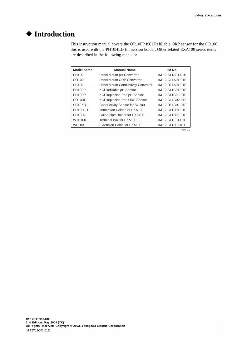
r IntroductionThis instruction manual covers the OR10FP KCl Refillable ORP sensor for the OR100;this is used with the PH10HLD Immersion holder. Other related EXA100 series itemsare described in the following manuals:
T000.eps
Model name Manual Name IM No.
PH100 Panel Mount pH Converter IM 12 B11A01-01E
OR100 Panel Mount ORP Converter IM 12 C11A01-01E
SC100 Panel Mount Conductivity Converter IM 12 D11A01-01E
PH10FP KCl Refillable pH Sensor IM 12 B11C01-01E
PH10RP KCl Replenish-free pH Sensor IM 12 B11C02-01E
OR10RP KCl Replenish-free ORP Sensor IM 12 C11C02-01E
SC10XB Conductivity Sensor for SC100 IM 12 D11C01-01E
PH10HLD Immersion Holder for EXA100 IM 12 B11D01-01E
PH10HG Guide-pipe Holder for EXA100 IM 12 B11D02-01E
WTB100 Terminal Box for EXA100 IM 12 B11E01-01E
WF100 Extension Cable for EXA100 IM 12 B11F01-01E
IM 12C11C01-01Eii
r For the safe use of this equipment(1) About This Manual
• This manual should be passed on to the end user.• The contents of this manual are subject to change without prior notice.• The contents of this manual shall not be reproduced or copied, in part or in whole,
without permission.• This manual explains the functions contained in this product, but does not warrant that
they are suitable the particular purpose of the user.• Every effort has been made to ensure accuracy in the preparation of this manual.
However, when you realize mistaken expressions or omissions, please contact thenearest Yokogawa Electric representative or sales office.
• This manual does not cover the special specifications. This manual may be leftunchanged on any change of specification, construction or parts when the change doesnot affect the functions or performance of the product.
• If the product is not used in a manner specified in this manual, the safety of thisproduct may be impaired.
(2) Safety and Modification Precautions
• Follow the safety precautions in this manual when using the product to ensure protec-tion and safety of the human body, the product and the system containing the product.
(3) The following safety symbols are used on the product as well as in this manual.
DANGER
This symbol indicates that an operator must follow the instructions laid out in thismanual in order to avoid the risks, for the human body, of injury, electric shock, orfatalities. The manual describes what special care the operator must take to avoid suchrisks.
WARNINGThis symbol indicates that the operator must refer to the instructions in this manual inorder to prevent the instrument (hardware) or software from being damaged, or a systemfailure from occurring.
CAUTION
This symbol gives information essential for understanding the operations and functions.
TipThis symbol gives information that complements the current topic.
SEE ALSOThis symbol identifies a source to be referred to.
This symbol indicates Protective Ground Terminal
This symbol indicates Function Ground Terminal (Do not use this terminal asthe protective ground terminal.)
This symbol indicates Alternating current
iii
Safety Precautions
IM 12C11C01-01E
WARNING : Glass Breakage
Since the sensor contains a glass electrode, do not apply physical shock or excessiveforce to it. Breakage may occur.
IM 12C11C01-01Eiv
r After-sales Warrantyd For repair during the warranty period, carry or send the product to the local sales
representative or service office. Yokogawa will replace or repair any damaged partsand return the product to you.
d Before returning a product for repair under warranty, give us information of themodel name and serial number and a description of the problem. Any diagrams ordata explaining the problems would also be appreciated.
d If we replace the product with a new one, we won’t provide you with a repair report.
d Yokogawa warrants the product for the period stated in the purchase quotation.Yokogawa shall conduct warranty service based on its standard. When the customersite is outside of the service area, a fee for dispatching the maintenance engineer willbe charged to the customer.
d In the following cases, customer will be charged for repair fee regardless of warrantyperiod.
• Failure of components which are out of scope of warranty stated in instructionmanual.
• Failure caused by usage of software, hardware or auxiliary equipment, whichYokogawa Electric did not supply.
• Failure due to improper or insufficient maintenance by user.
• Failure due to modification, misuse or outside-of-specifications operation whichYokogawa does not authorize.
• Failure due to power supply (voltage, frequency) being outside specifications orabnormal.
• Failure caused by any usage out of scope of recommended usage.
• Any damage from fire, earthquake, storms and floods, lightning, disturbances, riots,warfare, radiation and other natural changes.
d Yokogawa does not warrant conformance with the specific application at the usersite. Yokogawa will not bear direct/indirect responsibility for damage due to a specificapplication.
d Yokogawa Electric will not bear responsibility when the user configures the productinto systems or resells the product.
d Our maintenance service and the supply of repair parts will be covered for five yearsafter the production ends. For product repair, please contact the nearest sales officedescribed in this instruction manual.
vIM 12C11C01-01E
Table of Contents
r Introduction ...................................................................................................................... i
r For the safe use of this equipment ................................................................................ ii
r After-sales Warranty ..................................................................................................... iv
1. Specification ................................................................................................................ 1-1
1.1 Standard Specifications ................................................................................... 1-11.2 Model and Suffix code .................................................................................... 1-21.3 External Dimensions ....................................................................................... 1-2
2. Installation .................................................................................................................. 2-1
2.1 Preparation for Installation ............................................................................. 2-12.1.1 Checking for Damage .............................................................................. 2-12.1.2 Installation of the Holder ....................................................................... 2-12.1.3 Installation of Associated Equipments .................................................... 2-1
2.2 Procedure for mounting the ORP sensor in the immersion holder ................ 2-22.3 ORP Sensor Cable Wiring Procedure ............................................................. 2-6
2.3.1 Connecting to a WTB100 terminal box .................................................. 2-62.3.2 Connecting to an EXA OR100 ORP converter ...................................... 2-8
3. Maintenance on operation......................................................................................... 3-1
3.1 Calibration and Periodic Maintenance ............................................................ 3-13.1.1 Check or calibration ................................................................................ 3-13.1.2 Washing of platinum electrode and liquid junction................................ 3-2 3.1.3 Filling up KCl solution in the holder. ..................................................... 3-2
3.2 Replacement of consumables .......................................................................... 3-3
Revision Record .................................................................................................................... i

IM 12C11C01-01Evi
IM 12C11C01-01E 1-1
1. Specification
1. Specification
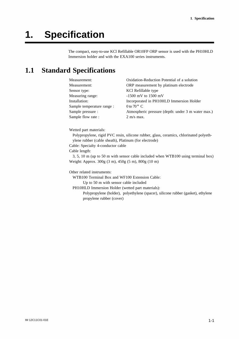
The compact, easy-to-use KCl Refillable OR10FP ORP sensor is used with the PH10HLDImmersion holder and with the EXA100 series instruments.
1.1 Standard SpecificationsMeasurement: Oxidation-Reduction Potential of a solutionMeasurement: ORP measurement by platinum electrodeSensor type: KCl Refillable typeMeasuring range: -1500 mV to 1500 mVInstallation: Incorporated in PH10HLD Immersion HolderSample temperature range : 0 to 70 8 CSample pressure : Atmospheric pressure (depth: under 3 m water max.)Sample flow rate : 2 m/s max.
Wetted part materials:Polypropylene, rigid PVC resin, silicone rubber, glass, ceramics, chlorinated polyeth-ylene rubber (cable sheath), Platinum (for electrode)
Cable: Specialty 4-conductor cableCable length:
3, 5, 10 m (up to 50 m with sensor cable included when WTB100 using terminal box)Weight: Approx. 300g (3 m), 450g (5 m), 800g (10 m)
Other related instruments:WTB100 Terminal Box and WF100 Extension Cable:
Up to 50 m with sensor cable includedPH10HLD Immersion Holder (wetted part materials):
Polypropylene (holder), polyethylene (spacer), silicone rubber (gasket), ethylenepropylene rubber (cover)
IM 12C11C01-01E1-2
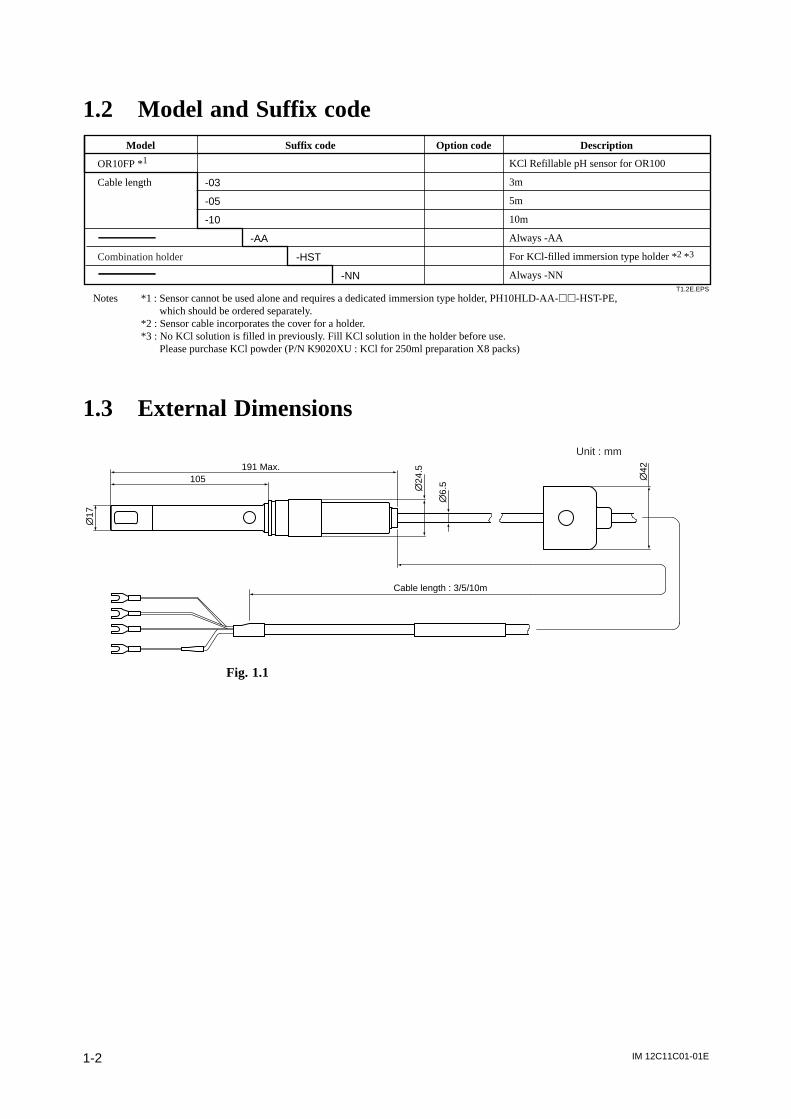
1.2 Model and Suffix code
T1.2E.EPS
-03
-05
-10
-AA
-HST
-NN
KCl Refillable pH sensor for OR100
3m
5m
10m
Always -AA
For KCl-filled immersion type holder *2 *3
Always -NN
Model Suffix code Option code Description
OR10FP *1
Cable length
Combination holder
Notes *1 : Sensor cannot be used alone and requires a dedicated immersion type holder, PH10HLD-AA-hh-HST-PE, which should be ordered separately.
*2 : Sensor cable incorporates the cover for a holder. *3 : No KCl solution is filled in previously. Fill KCl solution in the holder before use. Please purchase KCl powder (P/N K9020XU : KCl for 250ml preparation X8 packs)
1.3 External Dimensions
Cable length : 3/5/10m
105
\17
\24
.5
\6.
5
\42191 Max.
Unit : mm
Fig. 1.1
IM 12C11C01-01E 2-1
2. Installation
2. Installation
2.1 Preparation for Installation
2.1.1 Checking for Damage
The OR10FP KCl Refillable ORP sensor is carefully packed to avoid damage duringtransportation. However, when you receive it, carefully unpack it and check visibledamage.
2.1.2 Installation of the Holder
The OR10FP KCI-Refillable ORP sensor used with PH10HLD Immersion holder. Checkthe holder can be / is installed in a place you select.
2.1.3 Installation of Associated Equipments
Check that associated equipments such as the WTB100 terminal box or the OR100 ORPconverter is installed.

IM 12C11C01-01E2-2
2.2 Procedure for mounting the ORP sensor in the immer-sion holder
(1) Take the cap ] that prevents the ORP sensor from drying out ] off the tip of thesensor.
(2) Remouve the tape covering the KCl filling hole of sensor.Mount the sensor in the immersion holder as the following procedures.• Loosen the Lock nut on the tip of the immersion holder• Remove the nut, a washer and gasket.• Pass the sensor through the holder as the direction of the black arrow in Fig. 2.1• Push out the sensor until it sticks out other pipe side.• Insert the sensor into the removed gasket until it reaches the index lip.(See Fig 2.2)• Attach the sensor equipped with the gasket to the guide pipe.• Putting the removed washer between the gasket and the nut, tighten the nut so strongly to hold them in place. In Fig. 2.1, the white arrow indicates the insert direction of the gasket, washer, and nut.• Set the cap cover to the waterproofing cap of the holder guide pipe.
F2.1.eps
Rubber cap
Holder guide pipe
KCl Refillable ORP sensor
Silicon gasket forholding ORP sensor
Washer
Lock nut for fixingthe sensor
Fig. 2.1
F2.2E.eps
KCl refilling hole
KCl Refillable ORP sensorSilicon gasket forfixing ORP sensor
Gasketposition
Index lip
KCl refillinghole side
Fig. 2.2
IM 12C11C01-01E 2-3
2. Installation
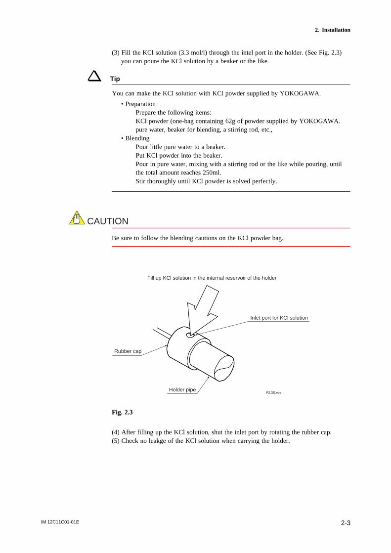
(3) Fill the KCl solution (3.3 mol/l) through the intel port in the holder. (See Fig. 2.3)you can poure the KCl solution by a beaker or the like.
Tip
You can make the KCl solution with KCl powder supplied by YOKOGAWA.
• PreparationPrepare the following items:KCl powder (one-bag containing 62g of powder supplied by YOKOGAWA.pure water, beaker for blending, a stirring rod, etc.,
• BlendingPour little pure water to a beaker.Put KCl powder into the beaker.Pour in pure water, mixing with a stirring rod or the like while pouring, untilthe total amount reaches 250ml.Stir thoroughly until KCl powder is solved perfectly.
CAUTION
Be sure to follow the blending cautions on the KCl powder bag.
F2.3E.eps
Rubber cap
Holder pipe
Fill up KCl solution in the internal reservoir of the holder
Inlet port for KCl solution
Fig. 2.3
(4) After filling up the KCl solution, shut the inlet port by rotating the rubber cap.(5) Check no leakge of the KCl solution when carrying the holder.
IM 12C11C01-01E2-4
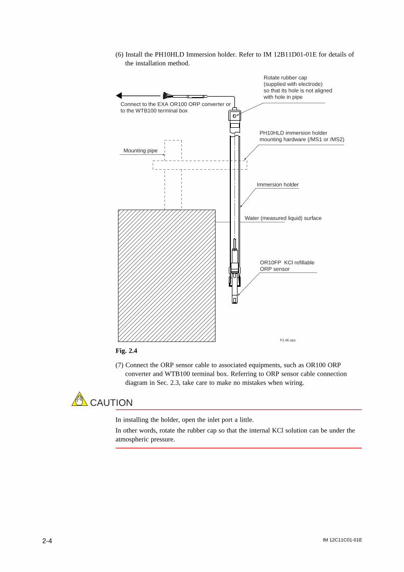
(6) Install the PH10HLD Immersion holder. Refer to IM 12B11D01-01E for details ofthe installation method.
F2.4E.eps
Connect to the EXA OR100 ORP converter or to the WTB100 terminal box
Rotate rubber cap (supplied with electrode) so that its hole is not aligned with hole in pipe
PH10HLD immersion holder mounting hardware (/MS1 or /MS2)
Immersion holder
Mounting pipe
Water (measured liquid) surface
OR10FP KCl refillable ORP sensor
Fig. 2.4
(7) Connect the ORP sensor cable to associated equipments, such as OR100 ORPconverter and WTB100 terminal box. Referring to ORP sensor cable connectiondiagram in Sec. 2.3, take care to make no mistakes when wiring.
CAUTION
In installing the holder, open the inlet port a little.
In other words, rotate the rubber cap so that the internal KCl solution can be under theatmospheric pressure.
IM 12C11C01-01E 2-5
2. Installation
CAUTION
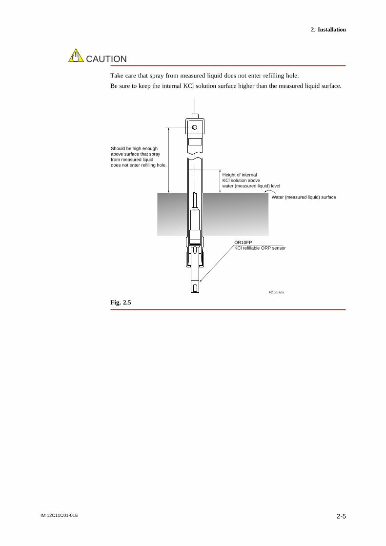
Take care that spray from measured liquid does not enter refilling hole.
Be sure to keep the internal KCl solution surface higher than the measured liquid surface.
F2.5E.eps
Water (measured liquid) surface
Height of internal KCl solution above water (measured liquid) level
OR10FPKCl refillable ORP sensor
Should be high enough above surface that spray from measured liquid does not enter refilling hole.
Fig. 2.5
IM 12C11C01-01E2-6
2.3 ORP Sensor Cable Wiring Procedure
CAUTION
Place ORP sensor cable wiring as far as possible from power supply and ground wiring.
2.3.1 Connecting to a WTB100 terminal box
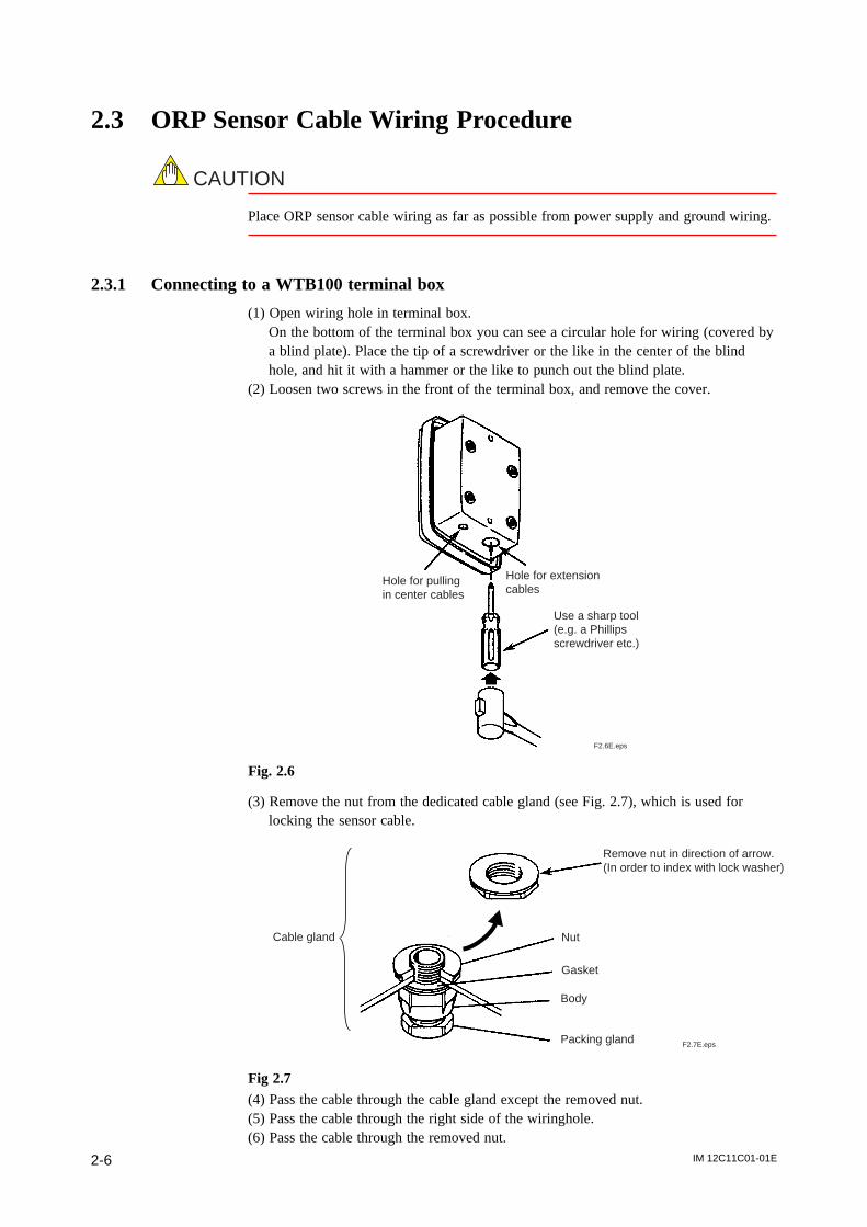
(1) Open wiring hole in terminal box.On the bottom of the terminal box you can see a circular hole for wiring (covered bya blind plate). Place the tip of a screwdriver or the like in the center of the blindhole, and hit it with a hammer or the like to punch out the blind plate.
(2) Loosen two screws in the front of the terminal box, and remove the cover.
F2.6E.eps
Use a sharp tool (e.g. a Phillips screwdriver etc.)
Hole for pulling in center cables
Hole for extension cables
Fig. 2.6
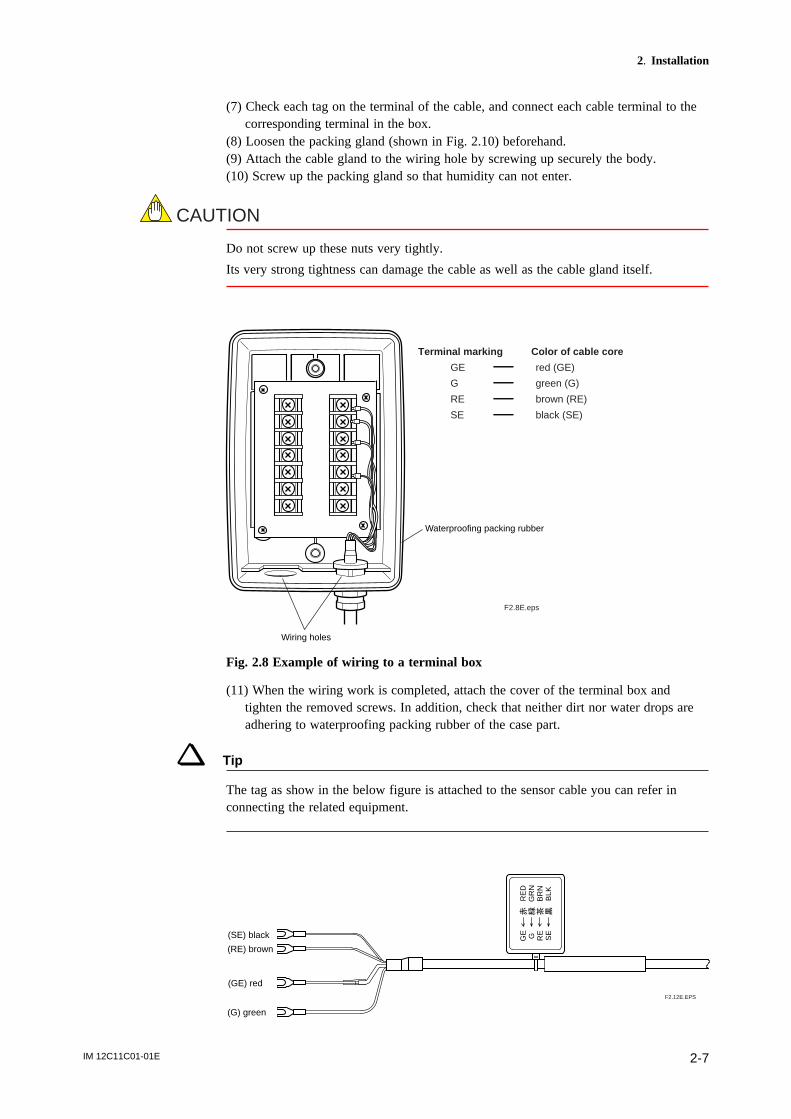
(3) Remove the nut from the dedicated cable gland (see Fig. 2.7), which is used forlocking the sensor cable.
F2.7E.eps
Remove nut in direction of arrow. (In order to index with lock washer)
Nut
Gasket
Body
Packing gland
Cable gland
Fig 2.7(4) Pass the cable through the cable gland except the removed nut.(5) Pass the cable through the right side of the wiringhole.(6) Pass the cable through the removed nut.
IM 12C11C01-01E 2-7
2. Installation
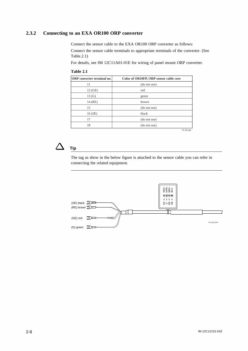
(7) Check each tag on the terminal of the cable, and connect each cable terminal to thecorresponding terminal in the box.
(8) Loosen the packing gland (shown in Fig. 2.10) beforehand.(9) Attach the cable gland to the wiring hole by screwing up securely the body.(10) Screw up the packing gland so that humidity can not enter.
CAUTION
Do not screw up these nuts very tightly.
Its very strong tightness can damage the cable as well as the cable gland itself.
F2.8E.eps
Terminal marking Color of cable core
GE red (GE)
G green (G)
RE brown (RE)
SE black (SE)
Waterproofing packing rubber
Wiring holes
Fig. 2.8 Example of wiring to a terminal box
(11) When the wiring work is completed, attach the cover of the terminal box andtighten the removed screws. In addition, check that neither dirt nor water drops areadhering to waterproofing packing rubber of the case part.
Tip
The tag as show in the below figure is attached to the sensor cable you can refer inconnecting the related equipment.
GE G RE
SE
RE
DG
RN
BR
NB
LK
(G) green
(GE) red
(RE) brown
(SE) black
F2.12E.EPS
IM 12C11C01-01E2-8
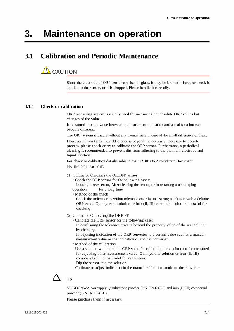
2.3.2 Connecting to an EXA OR100 ORP converter
Connect the sensor cable to the EXA OR100 ORP converter as follows:
Connect the sensor cable terminals to appropriate terminals of the converter. (SeeTable.2.1)
For details, see IM 12C11A01-01E for wiring of panel mount ORP converter.
Table 2.1
ORP converter terminal no. Color of OR10FP, ORP sensor cable core
11 (do not use)
12 (GE) red
13 (G) green
14 (RE) brown
15 (do not use)
16 (SE) black
17 (do not use)
18 (do not use)T2.1E.eps
Tip
The tag as show in the below figure is attached to the sensor cable you can refer inconnecting the related equipment.
GE G RE
SE
RE
DG
RN
BR
NB
LK
(G) green
(GE) red
(RE) brown
(SE) black
F2.12E.EPS
IM 12C11C01-01E 3-1
3. Maintenance on operation
3. Maintenance on operation
3.1 Calibration and Periodic Maintenance
CAUTION
Since the electrode of ORP sensor consists of glass, it may be broken if force or shock isapplied to the sensor, or it is dropped. Please handle it carefully.
3.1.1 Check or calibration
ORP measuring system is usually used for measuring not absolute ORP values butchanges of the value.
It is natural that the value between the instrument indication and a real solution canbecome different.
The ORP system is usable without any maintenance in case of the small difference of them.
However, if you think their difference is beyond the accuracy necessary to operateprocess, please check or try to calibrate the ORP sensor. Furthermore, a periodicalcleaning is recommended to prevent dirt from adhering to the platinum electrode andliquid junction.
For check or calibration details, refer to the OR100 ORP converter: Document
No. IM12C11A01-01E.
(1) Outline of Checking the OR10FP sensor• Check the ORP sensor for the following cases: In using a new sensor, After cleaning the sensor, or in restarting after stoppingoperation for a long time• Method of the check Check the indication is within tolerance error by measuring a solution with a definite ORP value. Quinhydrone solution or iron (II, III) compound solution is useful for checking.
(2) Outline of Calibrating the OR10FP• Calibrate the ORP sensor for the following case: In confirming the tolerance error is beyond the property value of the real solution by checking In adjusting indication of the ORP converter to a certain value such as a manual measurement value or the indication of another converter.• Method of the calibration
Use a solution with a definite ORP value for calibration, or a solution to be measured for adjusting other measurement value. Quinhydrone solution or iron (II, III) compound solution is useful for calibration. Dip the sensor into the solution.
Calibrate or adjust indication in the manual calibration mode on the converter
Tip
YOKOGAWA can supply Quinhydrone powder (P/N: K9024EC) and iron (II, III) compoundpowder (P/N: K9024ED).
Please purchase them if necessary.
IM 12C11C01-01E3-2
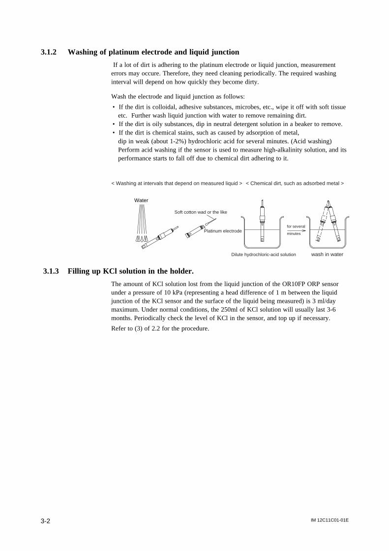
3.1.2 Washing of platinum electrode and liquid junction
If a lot of dirt is adhering to the platinum electrode or liquid junction, measurementerrors may occure. Therefore, they need cleaning periodically. The required washinginterval will depend on how quickly they become dirty.
Wash the electrode and liquid junction as follows:
• If the dirt is colloidal, adhesive substances, microbes, etc., wipe it off with soft tissueetc. Further wash liquid junction with water to remove remaining dirt.
• If the dirt is oily substances, dip in neutral detergent solution in a beaker to remove.• If the dirt is chemical stains, such as caused by adsorption of metal,
dip in weak (about 1-2%) hydrochloric acid for several minutes. (Acid washing)Perform acid washing if the sensor is used to measure high-alkalinity solution, and itsperformance starts to fall off due to chemical dirt adhering to it.
for several
minutes
< Washing at intervals that depend on measured liquid > < Chemical dirt, such as adsorbed metal >
Water
Soft cotton wad or the like
Platinum electrode
Dilute hydrochloric-acid solution wash in water
3.1.3 Filling up KCl solution in the holder.
The amount of KCl solution lost from the liquid junction of the OR10FP ORP sensorunder a pressure of 10 kPa (representing a head difference of 1 m between the liquidjunction of the KCl sensor and the surface of the liquid being measured) is 3 ml/daymaximum. Under normal conditions, the 250ml of KCl solution will usually last 3-6months. Periodically check the level of KCl in the sensor, and top up if necessary.
Refer to (3) of 2.2 for the procedure.
IM 12C11C01-01E 3-3
3. Maintenance on operation
3.2 Replacement of consumables
d Replacement of OR10FP KCl Refillable sensorThe OR10FP sensor has limited life. When it can no longer be calibrated withstandard solution, it should be replaced.
CAUTION
• Take care not to hit the electrode and the junction to a rigid place.• Take care not to let the electrode and the junction touch a ground.• Dip the sensor in a solution to be measured as early as possible, because a measure-
ment drift may occur right after immersing the senor in the solution,• Keep in mind the OR10FP cannot apply to a chromium coating process solution
because of the platinum electrode tolerance.• Be careful not to allow the liquid junction to dry out.
When storing the ORP sensor or keeping it in air for long time, be sure to attach theprotective cap (supplied with it when it is shipped) to its tip.If the protective cap has been lost, then store the sensor with its tip immersed in tapwater to keep the liquid junction wet.
d Replacing the gasket in the PH10HLD Immersion holderFor the PH10HLD immersion holder, the sealing characteristics of the silicon gasketdo not usually deteriorate if it is unused for a short time, so replacement of the silicongasket alone is usually not required. If, however, deterioration of the silicon gasket isnoticeable, replace it. Use only silicon gaskets supplied by Yokogawa.

IM 12C11C01-01E3-4
Revision Record
Manual Title : Model OR10FP KCl Refillable ORP sensor
Manual Number : IM 12C11C01-01E
Edition Date Remark (s)
1st May. 2003 Newly published
2nd May 2004 OR100 shield cover changed