oracle8i spatial - department of computer science and ........ 6-7 sdo_tune.extent_of..... 6-8...
TRANSCRIPT

Oracle8 i Spatial
User’s Guide and Reference
Release 8.1.5
February 1999
Part No. A67295-01

Oracle8i Spatial User’s Guide and Reference
Part No. A67295-01
Release 8.1.5
Copyright © 1999, Oracle Corporation. All rights reserved.
Primary Author: Jeff Hebert
Contributing Author: Anna Logan
Contributors: Frank Wang, Siva Ravada, Ran Wei, Jayant Sharma, and Dan Geringer
The programs are not intended for use in any nuclear, aviation, mass transit, medical, or otherinherently dangerous applications. It shall be licensee's responsibility to take all appropriatefail-safe, back up, redundancy and other measures to ensure the safe use of such applications if thePrograms are used for such purposes, and Oracle disclaims liability for any damages caused by suchuse of the Programs.
This Program contains proprietary information of Oracle Corporation; it is provided under a licenseagreement containing restrictions on use and disclosure and is also protected by copyright, patent andother intellectual property law. Reverse engineering of the software is prohibited.
The information contained in this document is subject to change without notice. If you find anyproblems in the documentation, please report them to us in writing. Oracle Corporation does notwarrant that this document is error free. No part of this document may be reproduced or transmitted inany form or by any means, electronic or mechanical, for any purpose, without the express writtenpermission of Oracle Corporation
If this Program is delivered to a U.S. Government Agency of the Department of Defense, then it isdelivered with Restricted Rights and the following legend is applicable:
Restricted Rights Legend Programs delivered subject to the DOD FAR Supplement are "commercialcomputer software" and use, duplication and disclosure of the Programs shall be subject to the licensingrestrictions set forth in the applicable Oracle license agreement. Otherwise, Programs delivered subjectto the Federal Acquisition Regulations are "restricted computer software" and use, duplication anddisclosure of the Programs shall be subject to the restrictions in FAR 52.227-14, Rights in Data -- General,including Alternate III (June 1987). Oracle Corporation, 500 Oracle Parkway, Redwood City, CA 94065.
Oracle, SQL*Loader, SQL*Net, and SQL*Plus are registered trademarks, and Oracle7 and Oracle8i aretrademarks of Oracle Corporation. All other company or product names mentioned are used foridentification purposes only and may be trademarks of their respective owners.

Contents
Send Us Your Comments .................................................................................................................. xv
Preface ......................................................................................................................................................... xvii
1 Spatial Concepts
1.1 What Is the Spatial Product?................................................................................................ 1-11.2 Introduction to Spatial Data................................................................................................. 1-21.3 Geometric Types for Relational and Object-Relational Models ..................................... 1-31.4 Data Model ............................................................................................................................. 1-41.4.1 Element ............................................................................................................................ 1-51.4.2 Geometry ......................................................................................................................... 1-51.4.3 Layer................................................................................................................................. 1-61.5 Query Model .......................................................................................................................... 1-61.6 Indexing Methods ................................................................................................................. 1-71.6.1 Tessellation of a Layer During Indexing .................................................................... 1-91.6.2 Fixed Indexing ................................................................................................................ 1-91.6.3 Hybrid Indexing........................................................................................................... 1-141.7 Spatial Relations and Filtering .......................................................................................... 1-171.8 Partitioned Point Data ........................................................................................................ 1-20
Part I Object-Relational Model
2 The Object-Relational Schema
2.1 Object-Relational Data Structures....................................................................................... 2-12.2 Geometry Examples Using the Object-Relational Model................................................ 2-6
iii

2.3 Geometry Metadata Structure ............................................................................................. 2-92.4 Spatial Index-Related Structure......................................................................................... 2-112.4.1 Spatial Index Tables ..................................................................................................... 2-112.4.2 Spatial Index Data Dictionary View .......................................................................... 2-122.5 Usage Notes.......................................................................................................................... 2-13
3 Loading and Indexing Spatial Object Types
3.1 Load Process........................................................................................................................... 3-13.1.1 Bulk Loading................................................................................................................... 3-13.1.1.1 Bulk Loading the SDO_GEOMETRY Object....................................................... 3-23.1.1.2 Bulk Loading Point-Only Data in the SDO_GEOMETRY Object .................... 3-33.1.2 Transactional Insert Using SQL.................................................................................... 3-33.1.2.1 Polygon with Hole .................................................................................................. 3-43.1.2.2 Compound Line String........................................................................................... 3-53.1.2.3 Compound Polygon................................................................................................ 3-63.1.2.4 Compound Polygon with Holes ........................................................................... 3-73.1.2.5 Transactional Insert of Point-Only Data .............................................................. 3-93.2 Index Creation........................................................................................................................ 3-93.2.1 Determining Index Creation Behavior ...................................................................... 3-103.2.2 Spatial Indexing with Fixed-Size Tiles ...................................................................... 3-103.2.3 Hybrid Spatial Indexing with Fixed-Size and Variable-Sized Tiles ..................... 3-13
4 Querying Spatial Data
4.1 Query Model .......................................................................................................................... 4-14.2 Spatial Query.......................................................................................................................... 4-14.2.1 Primary Filter .................................................................................................................. 4-44.2.2 Primary and Secondary Filter....................................................................................... 4-54.2.3 Within Distance Operator ............................................................................................. 4-74.3 Spatial Join .............................................................................................................................. 4-8
5 Indexing Statements for Object Relational Model
ALTER INDEX ....................................................................................................................... 5-2
ALTER INDEX REBUILD..................................................................................................... 5-5
ALTER INDEX RENAME TO.............................................................................................. 5-8
iv
CREATE INDEX .................................................................................................................... 5-9
DROP INDEX....................................................................................................................... 5-13
6 Tuning Functions and Procedures for Object-Relational Model
SDO_TUNE.AVERAGE_MBR............................................................................................. 6-2
SDO_TUNE.ESTIMATE_INDEX_PERFORMANCE ....................................................... 6-3
SDO_TUNE.ESTIMATE_TILING_LEVEL ........................................................................ 6-5
SDO_TUNE.ESTIMATE_TILING_TIME ........................................................................... 6-7
SDO_TUNE.EXTENT_OF .................................................................................................... 6-8
SDO_TUNE.HISTOGRAM_ANALYSIS ............................................................................ 6-9
SDO_TUNE.MIX_INFO ..................................................................................................... 6-11
7 Geometry Functions for Object-Relational Model
SDO_GEOM.AREA............................................................................................................... 7-2
SDO_GEOM.LENGTH ......................................................................................................... 7-3
SDO_GEOM.RELATE........................................................................................................... 7-4
SDO_GEOM.SDO_BUFFER................................................................................................. 7-6
SDO_GEOM.SDO_POLY_DIFFERENCE .......................................................................... 7-7
SDO_GEOM.SDO_POLY_INTERSECTION ..................................................................... 7-8
SDO_GEOM.SDO_POLY_UNION..................................................................................... 7-9
SDO_GEOM.SDO_POLY_XOR......................................................................................... 7-10
SDO_GEOM.VALIDATE_GEOMETRY........................................................................... 7-11
SDO_GEOM.VALIDATE_LAYER.................................................................................... 7-13
SDO_GEOM.WITHIN_DISTANCE.................................................................................. 7-15
8 Migration Procedures
SDO_MIGRATE.TO_734 ...................................................................................................... 8-2
SDO_MIGRATE.TO_81X ..................................................................................................... 8-3
SDO_MIGRATE.OGIS_METADATA_FROM................................................................... 8-5
SDO_MIGRATE.OGIS_METADATA_TO......................................................................... 8-6
v

9 Spatial Operators
SDO_FILTER .......................................................................................................................... 9-2
SDO_RELATE ........................................................................................................................ 9-4
SDO_WITHIN_DISTANCE ................................................................................................. 9-7
Part II Relational Model
10 The Relational Schema
10.1 Database Structures for the Relational Implementation................................................ 10-1
11 Loading Spatial Data
11.1 Load Model........................................................................................................................... 11-111.2 Load Process......................................................................................................................... 11-211.2.1 Bulk Loading................................................................................................................. 11-211.2.2 Transactional Insert Using SQL.................................................................................. 11-411.3 Index Creation...................................................................................................................... 11-611.3.1 Choosing a Tessellation Algorithm ........................................................................... 11-611.3.2 Spatial Indexing with Fixed-Size Tiles ...................................................................... 11-711.3.3 Hybrid Spatial Indexing with Fixed-Size and Variable-Sized Tiles ................... 11-10
12 Querying Spatial Data
12.1 Query Model ........................................................................................................................ 12-112.2 Spatial Index Data Structures ............................................................................................ 12-112.3 Spatial Query........................................................................................................................ 12-412.3.1 Dynamic Query Window ............................................................................................ 12-512.3.2 Primary Filter Query.................................................................................................... 12-612.3.3 Secondary Filter Query............................................................................................... 12-712.4 Spatial Join ............................................................................................................................ 12-8
13 Administrative Functions and Procedures
SDO_ADMIN.POPULATE_INDEX.................................................................................. 13-3
SDO_ADMIN.POPULATE_INDEX_FIXED.................................................................... 13-5
SDO_ADMIN.POPULATE_INDEX_FIXED_POINTS ................................................... 13-8
vi

SDO_ADMIN.SDO_CODE_SIZE ................................................................................... 13-10
SDO_ADMIN.SDO_VERSION........................................................................................ 13-11
SDO_ADMIN.UPDATE_INDEX .................................................................................... 13-12
SDO_ADMIN.UPDATE_INDEX_FIXED....................................................................... 13-14
SDO_ADMIN.VERIFY_LAYER ...................................................................................... 13-16
14 Tuning Functions and Procedures
SDO_TUNE.AVERAGE_MBR........................................................................................... 14-2
SDO_TUNE.ESTIMATE_INDEX_PERFORMANCE ..................................................... 14-3
SDO_TUNE.ESTIMATE_TILING_LEVEL ...................................................................... 14-5
SDO_TUNE.ESTIMATE_TILING_TIME ......................................................................... 14-8
SDO_TUNE.EXTENT_OF .................................................................................................. 14-9
SDO_TUNE.HISTOGRAM_ANALYSIS ........................................................................ 14-10
SDO_TUNE.MIX_INFO ................................................................................................... 14-12
15 Geometry Functions and Procedures
SDO_GEOM.RELATE......................................................................................................... 15-2
SDO_GEOM.VALIDATE_GEOM..................................................................................... 15-5
SDO_GEOM.VALIDATE_LAYER.................................................................................... 15-7
16 Window Functions and Procedures
SDO_WINDOW.BUILD_WINDOW ................................................................................ 16-2
SDO_WINDOW.BUILD_WINDOW_FIXED................................................................... 16-4
SDO_WINDOW.CLEAN_WINDOW............................................................................... 16-6
SDO_WINDOW.CLEANUP_GID .................................................................................... 16-7
SDO_WINDOW.CREATE_WINDOW_LAYER ............................................................. 16-8
A Tuning Tips and Sample SQL Scripts
A.1 Selecting a Spatial Model ..................................................................................................... A-1A.1.1 Benefits of the Object-Relational Model...................................................................... A-1A.1.2 Benefits of the Relational Model .................................................................................. A-1
vii

A.2 Tuning Tips ............................................................................................................................ A-2A.2.1 Data Modeling ................................................................................................................ A-2A.2.2 Understanding the Tiling Level ................................................................................... A-2A.2.3 Database Sizing............................................................................................................... A-3A.2.4 Visualizing the Spatial Index (Drawing Tiles) ........................................................... A-4A.2.4.1 Drawing Tiles from the Object-Relational Model .............................................. A-5A.2.4.2 Drawing Tiles from the Relational Model ........................................................... A-6A.2.5 Performing Secondary Filter Queries and the Redo Log.......................................... A-8A.2.6 Tuning Point Data with the Relational Model ........................................................... A-8A.2.6.1 Efficient Queries for Relational Point Data ......................................................... A-8A.2.6.2 Efficient Schema for Relational Point Layers ...................................................... A-9A.2.6.3 Script for Using Table Partitioning with Relational Point Data .................... A-10A.2.7 Tuning Spatial Join Queries Using the Relational Model...................................... A-10A.2.7.1 Using the NO_MERGE, INDEX, and USE_NL Hints..................................... A-10A.2.7.2 Spatial Join Queries with Point Layers ............................................................. A-11A.2.8 Using Customized Geometry Types in the Relational Model .............................. A-13A.2.9 Partitioning Spatial Data Using the Relational Model........................................... A-13A.2.10 Parallel Loading and Indexing of Spatial Data Using the Relational Model...... A-14A.3 Scripts for Spatial Indexing Using the Relational Model.............................................. A-15A.3.1 cr_spatial_index.sql Script ......................................................................................... A-15A.3.2 crlayer.sql Script .......................................................................................................... A-16A.4 Tools and Related Products .............................................................................................. A-16A.4.1 Oracle8i interMedia Locator...................................................................................... A-16A.4.1.1 Geocoding Support .............................................................................................. A-16A.4.1.2 Compatibility with Spatial Objects.................................................................... A-17A.4.1.3 Sample Locator Code.......................................................................................... A-17A.4.2 Spatial Viewer on UNIX/Motif for Relational Model ........................................... A-18A.4.2.1 Installation and Setup.......................................................................................... A-18A.4.2.2 Connecting to a Database and Viewing Geometries....................................... A-18A.4.2.3 Using the Sample Viewer.................................................................................... A-19A.4.3 Spatial Visualizer on Windows NT for the Object-Relational Model.................. A-19A.4.3.1 Compiling and Running the Sample Program ................................................ A-20A.4.3.2 Usage Notes .......................................................................................................... A-20
viii

B Installation, Compatibility, and Migration Issues
B.1 Introduction........................................................................................................................... B-1B.2 Installation Details................................................................................................................. B-2B.2.1 Changing from 8.1 to 8.0 Compatibility Mode .......................................................... B-2B.3 Compatibility Details ............................................................................................................ B-3B.4 Data Migration Issues ........................................................................................................... B-4
C Partitioning Legacy Point Data
C.1 Overview ................................................................................................................................ C-1C.2 Partitioning Process .............................................................................................................. C-2C.3 Scripts for the Deprecated Partitioned Point Data Model............................................... C-3C.3.1 altpart.sql Script.............................................................................................................. C-3C.3.2 drppart.sql Script............................................................................................................ C-3C.3.3 sdogrant.sql Script.......................................................................................................... C-4C.4 Administrative Functions for the Deprecated Model ...................................................... C-4
SDO_ADMIN.ALTER_HIGH_WATER_MARK............................................................... C-5
SDO_ADMIN.DROP_PARTITION_INFO ........................................................................ C-6
SDO_ADMIN.PARTITION.................................................................................................. C-7
SDO_ADMIN.PROPAGATE_GRANTS ............................................................................ C-9
SDO_ADMIN.REGISTER_PARTITION_INFO ............................................................. C-10
SDO_ADMIN.REPARTITION.......................................................................................... C-11
SDO_ADMIN.VERIFY_PARTITIONS ............................................................................ C-12C.5 Data Functions .................................................................................................................... C-13
SDO_BVALUETODIM ...................................................................................................... C-14
SDO_COMPARE ................................................................................................................ C-15
SDO_DATETODIM............................................................................................................ C-17
SDO_DECODE.................................................................................................................... C-19
SDO_ENCODE ................................................................................................................... C-20
SDO_TO_BVALUE............................................................................................................. C-21
SDO_TO_DATE.................................................................................................................. C-22C.6 Data Dictionary................................................................................................................... C-23C.7 Messages and Codes .......................................................................................................... C-33
ix

Glossary
x

xi
List of Examples
3–1 Control File for a Bulk Load ................................................................................................ 3-23–2 Control File for a Bulk Load of Point-Only Data........................................................... 3-33–3 Create a Fixed Index ........................................................................................................... 3-134–1 Primary Filter with a Temporary Query Window ........................................................... 4-44–2 Primary Filter with a Transient Instance of the Query Window.................................... 4-54–3 Primary Filter with a Stored Query Window.................................................................... 4-54–4 Secondary Filter Using a Temporary Query Window..................................................... 4-64–5 Secondary Filter Using a Stored Query Window ............................................................. 4-611–1 Raw Data Format................................................................................................................. 11-211–2 Control File to Load Data into the Geometry Table....................................................... 11-311–3 Raw Data Format................................................................................................................. 11-311–4 Control File to Load from a Single Flat File..................................................................... 11-411–5 Transactional Insert............................................................................................................. 11-411–6 Transactional Insert for a Large Geometry...................................................................... 11-513–1 Populate an Index................................................................................................................ 13-413–2 Populate an Index with Fixed-Size Tiles.......................................................................... 13-713–3 Populate an Index with Fixed-Size Tiles Based on Point Data ..................................... 13-913–4 Update an Index ................................................................................................................ 13-1313–5 Update an Index with Fixed-Size Tiles .......................................................................... 13-1513–6 Verify a Layer..................................................................................................................... 13-1614–1 Recommended Tile Level for One-Degree Lat/Lon Cells ............................................ 14-614–2 Recommended Tile Level Based on the GIDs of All Geometries................................. 14-614–3 Recommended Tile Level Based on Average Extent of All Geometries ..................... 14-7A–1 View Fixed-Size Tiles for All Geometries .......................................................................... A-5A–2 View Variable-Sized Tiles for All Geometries................................................................... A-5A–3 View Fixed-Size Tiles for One Geometry........................................................................... A-6A–4 View Variable-Sized Tiles for One Geometry ................................................................... A-6A–5 View Fixed-Sized Tiles for All Geometries Using the Relational Model ...................... A-7A–6 View Fixed-Size Tiles for a Specific Geometry Using the Relational Model ................ A-8
xii
List of Figures
1–1 Geometric Primitive Types .................................................................................................. 1-31–2 New Geometry Types Using the Object-Relational Model ............................................. 1-41–3 Query Model .......................................................................................................................... 1-71–4 Quadtree Decomposition and Morton Codes ................................................................... 1-91–5 Fixed-Size Tiling with Many Small Tiles ......................................................................... 1-111–6 Fixed-Size Tiling with Fewer Large Tiles......................................................................... 1-121–7 Tessellated Figure................................................................................................................ 1-131–8 Variable-Sized Tile Spatial Indexing................................................................................. 1-151–9 Decomposition of the Geometry ....................................................................................... 1-161–10 The 9-Intersection Model.................................................................................................... 1-181–11 Distance Buffers for Points, Lines, and Polygons ........................................................... 1-202–1 Geometry with a Hole........................................................................................................... 2-72–2 Compound Element .............................................................................................................. 2-82–3 Compound Polygon .............................................................................................................. 2-93–1 Example Geometry OBJ_1 .................................................................................................... 3-43–2 Line String Consisting of Arcs and Straight Line Segments ........................................... 3-63–3 Compound Polygon .............................................................................................................. 3-73–4 Compound Polygon with a Hole ........................................................................................ 3-93–5 Sample Domain.................................................................................................................... 3-113–6 Fixed-Size Tiling at Level 1 ................................................................................................ 3-123–7 Fixed-Size Tiling at Level 2 ................................................................................................ 3-124–1 Tessellated Layer with Multiple Objects............................................................................ 4-24–2 Tessellated Layer with a Query Window .......................................................................... 4-310–1 Complex Polygon ................................................................................................................ 10-511–1 Sample GIS Domain ............................................................................................................ 11-811–2 Fixed-Size Tiling at Level 1 ................................................................................................ 11-811–3 Fixed-Size Tiling at Level 2 ................................................................................................ 11-912–1 Tessellated Layer with Multiple Objects.......................................................................... 12-212–2 Tessellated Layer with a Query Window ........................................................................ 12-512–3 Spatial Join of Two Layers.................................................................................................. 12-8
xiii
List of Tables
1–1 SDOINDEX Table Using Fixed-Size Tiles........................................................................ 1-131–2 Section of the SDOINDEX Table ....................................................................................... 1-172–1 Valid SDO_GTYPE Values................................................................................................... 2-22–2 Values and Semantics in SDO_ELEM_INFO .................................................................... 2-42–3 Columns in an SDO_INDEX_METADATA View.......................................................... 2-112–4 Columns in a Spatial Index Data Table............................................................................ 2-125–1 Spatial Index Creation and Usage Statements .................................................................. 5-15–2 SDO_LEVEL and SDO_NUMTILE Combinations ......................................................... 5-116–1 Tuning Functions and Procedures...................................................................................... 6-17–1 Geometric Functions for the Object-Relational Model .................................................... 7-18–1 Migration Procedures ........................................................................................................... 8-19–1 Spatial Usage Operators ....................................................................................................... 9-110–1 <layername>_SDOLAYER................................................................................................. 10-110–2 <layername>_SDODIM Table or View ............................................................................ 10-110–3 <layername>_SDOGEOM Table or View........................................................................ 10-210–4 <layername>_SDOINDEX Table ...................................................................................... 10-211–1 <layername>_SDOLAYER Table ...................................................................................... 11-111–2 <layername>_SDODIM Table or View ............................................................................ 11-111–3 <layername>_SDOGEOM Table or View........................................................................ 11-211–4 <layername>_SDOINDEX Table ...................................................................................... 11-211–5 Choosing a Tessellation Algorithm .................................................................................. 11-712–1 <layername>_SDOLAYER................................................................................................. 12-312–2 <layername>_SDOGEOM.................................................................................................. 12-312–3 <layername>_SDOINDEX ................................................................................................. 12-413–1 Administrative Procedures for Spatially Indexed Data................................................. 13-114–1 Tuning Functions and Procedures.................................................................................... 14-115–1 Geometric Functions and Procedures .............................................................................. 15-116–1 Window Functions and Procedures ................................................................................. 16-1C–1 Administrative Procedures for Partitioned Point Data ................................................... C-4C–2 Partitioned Point Data Functions..................................................................................... C-13

xiv

Send Us Your Comments
Oracle8 i Spatial User’s Guide and Reference, Release 8.1.5
Part No. A67295-01
Oracle Corporation welcomes your comments and suggestions on the quality and usefulness of thispublication. Your input is an important part of the information used for revision.
■ Did you find any errors?■ Is the information clearly presented?■ Do you need more information? If so, where?■ Are the examples correct? Do you need more examples?■ What features did you like most about this manual?
If you find any errors or have any other suggestions for improvement, please indicate the chapter,section, and page number (if available).
You can send comments to us in the following ways
■ e-mail: [email protected]■ FAX: 603.897.3316 Attn: Spatial Documentation■ postal service:
Oracle CorporationOracle8i Spatial DocumentationOne Oracle DriveNashua, NH 03062USA
If you would like a reply, please include your name, address, and telephone number.
xv

xvi
Preface
The Oracle8i Spatial User’s Guide and Reference provides user and referenceinformation for the Spatial product, and extensions to Oracle8i Enterprise Edition.
Spatial requires Oracle8i Enterprise Edition. Oracle8i and Oracle8i EnterpriseEdition have the same basic features. However, several advanced features, such asextended data types, are available only with the Enterprise Edition, and some ofthese features are optional. For example, to use Oracle8i table partitioning, youmust have the Enterprise Edition and the Partitioning Option.
For information about the differences between Oracle8i and Oracle8i EnterpriseEdition and the features and options that are available to you, see Getting to KnowOracle8i.
Intended AudienceThis guide is intended for anyone who needs to store spatial data in an Oracledatabase.
StructureThis guide is divided into two parts. Part I deals with the new object-relationalstorage model, and Part II describes the relational storage model. The followingtable lists the elements in this book:
Chapter 1 Introduces spatial data concepts.
Part I The following chapters describe the object-relational spatial model:
Chapter 2 Explains the object-relational schema.
xvii

Chapter 3 Explains loading and indexing spatial data.
Chapter 4 Explains methods for querying a spatial database.
Chapter 5 Provides the syntax and semantics for the indexing functions.
Chapter 6 Provides the syntax and semantics for the tuning functions andprocedures.
Chapter 7 Provides the syntax and semantics for the geometric functions andprocedures.
Chapter 8 Provides the syntax and semantics for the migration functions.
Chapter 9 Provides the syntax and semantics for operators used with thespatial object data type.
Part II The following chapters describe the relational spatial model:
Chapter 10 Explains the relational schema.
Chapter 11 Explains spatial data loading.
Chapter 12 Explains methods for querying a spatial database.
Chapter 13 Provides the syntax and semantics for the administrative functionsand procedures.
Chapter 14 Provides the syntax and semantics for the tuning functions andprocedures.
Chapter 15 Provides the syntax and semantics for the geometric functions andprocedures.
Chapter 16 Provides the syntax and semantics for the window functions andprocedures.
Appendix A Describes sample SQL scripts and tuning tips.
Appendix B Describes installation, compatibility, and migration issues.
Appendix C Describes how to use partitioned point data.
Glossary Provides definitions of terms used in this guide.
xviii

Related DocumentsFor more information, see the following manuals:
■ Oracle8i interMedia Locator User’s Guide and Reference
■ Getting to Know Oracle8i
■ Oracle8i Administrator’s Guide
■ Oracle8i Error Messages - Spatial messages are in the range of 13000 to 13499
■ Oracle8i Concepts
■ Oracle8i Tuning
■ Oracle8i Utilities
For additional information about the Spatial option, including a demonstrationprogram, several white papers, and other assorted collateral, visit the officialSpatial Web site: http://www.oracle.com/st/cartridges/spatial/
ConventionsIn examples, an implied carriage return occurs at the end of each line, unlessotherwise noted. You must press the Return key at the end of a line of input.
The following conventions are used in this guide:
Convention Meaning
. . .
Vertical ellipsis points in an example mean that informationnot directly related to the example has been omitted.
. . . Horizontal ellipsis points in statements or commands meanthat parts of the statement or command not directly related tothe example have been omitted
boldface text Boldface text indicates a term defined in the text, the glossary,or in both locations.
< > Angle brackets enclose user-supplied names.
[ ] Brackets enclose optional clauses from which you can chooseone or none.
% The percent sign represents the system prompt on a UNIXsystem.
xix

xx

Spatial Con
1
Spatial ConceptsOracle8i Spatial is an integrated set of functions and procedures that enables spatialdata to be stored, accessed, and analyzed quickly and efficiently in an Oracle8idatabase.
Spatial data represents the essential location characteristics of real or conceptualobjects as those objects relate to the real or conceptual space in which they exist.
1.1 What Is the Spatial Product?Oracle8i Spatial, often referred to as Spatial, provides a standard SQL schema andfunctions that facilitate the storage, retrieval, update, and query of collections ofspatial features in an Oracle8i database. It consists of four components:
1. A schema that prescribes the storage, syntax, and semantics of supportedgeometric data types
2. A spatial indexing mechanism
3. A set of operators and functions for performing area-of-interest and spatial joinqueries
4. Administrative utilities
The spatial attribute of a spatial feature is the geometric description of its shape insome coordinate space. This is referred to as its geometry.
This release of Spatial supports two mechanisms for representing geometry. Thefirst, an object-relational scheme, uses a table with single column of typeMDSYS.SDO_GEOMETRY and a single row per geometry instance. The second, arelational scheme, uses a table with a predefined set of columns of type NUMBERand one or more rows for each geometry instance. These mechanisms roughlycorrespond to two alternatives described in the OpenGIS ODBC/SQL specification
cepts 1-1
Introduction to Spatial Data
for geospatial features. The first corresponds to a “SQL with Geometry Types”implementation of spatial feature tables, and the second an implementation ofspatial feature tables using numeric SQL types for geometry storage.
Implementation-specific details are described in Part I "Object-Relational Model"and Part II "Relational Model" of this guide. The remainder of this chapterdescribes Spatial concepts and features, without reference to their implementationwherever possible.
1.2 Introduction to Spatial DataThe Spatial option is designed to make spatial data management easier and morenatural to users or applications such as a Geographic Information System (GIS).Once this data is stored in an Oracle database, it can be easily manipulated,retrieved, and related to all the other data stored in the database.
A common example of spatial data can be seen in a road map. A road map is atwo-dimensional object that contains points, lines, and polygons that can representcities, roads, and political boundaries such as states or provinces. A road map is avisualization of geographic information. The location of cities, roads, and politicalboundaries that exist on the surface of the Earth are projected onto atwo-dimensional display or piece of paper, preserving the relative positions andrelative distances of the rendered objects.
The data that indicates the Earth location (latitude and longitude, or height anddepth) of these rendered objects is the spatial data. When the map is rendered, thisspatial data is used to project the locations of the objects on a two-dimensionalpiece of paper. A GIS is often used to store, retrieve, and render this Earth-relativespatial data.
Other types of spatial data that can be stored using the Spatial option besides GISdata include data from computer-aided design (CAD) and computer-aidedmanufacturing (CAM) systems. Instead of operating on objects on a geographicscale, CAD/CAM systems work on a smaller scale such as for an automobileengine or printed circuit boards.
The differences among these three systems are only in the scale of the data, not itscomplexity. They might all actually involve the same number of data points. On ageographic scale, the location of a bridge can vary by a few tenths of an inchwithout causing any noticeable problems to the road builders. Whereas, if thediameter of an engine’s pistons are off by a few tenths of an inch, the engine willnot run. A printed circuit board is likely to have many thousands of objects etched
1-2 Oracle8i Spatial User’s Guide and Reference

Geometric Types for Relational and Object-Relational Models
on its surface that are no bigger than the smallest detail shown on a road builder’sblueprints.
These applications all store, retrieve, update, or query some collection of featuresthat have both nonspatial and spatial attributes. Examples of nonspatial attributesare name, soil_type, landuse_classification, and part_number. The spatial attributeis a coordinate geometry, or vector-based representation of the shape of the feature.The spatial attribute, referred to as the geometry, is an ordered sequence of verticesthat are connected by straight line segments or circular arcs. The semantics of thegeometry are determined by its type, which may be one of point, line string, orpolygon.
1.3 Geometric Types for Relational and Object-Relational ModelsThe relational model of the Spatial option supports three geometric primitive typesand geometries composed of collections of these types. The three primitive typesare as follows:
■ 2-D Point and Point Cluster
■ 2-D Line Strings
■ 2-D N-Point Polygons
2-D points are elements composed of two ordinates, X and Y, often correspondingto longitude and latitude. Line strings are composed of one or more pairs of pointsthat define line segments. Polygons are composed of connected line strings thatform a closed ring and the interior of the polygon is implied. Figure 1–1 illustratesthe supported geometric primitive types.
Figure 1–1 Geometric Primitive Types
Self-crossing polygons are not supported although self-crossing line strings are. If aline string crosses itself, it does not become a polygon. A self-crossing line stringdoes not have any implied interior.
Point . . .
. ..
.
. .
.Line String Polygon
Spatial Concepts 1-3

Data Model
The object-relational implementation supports the types listed in Figure 1–1, aswell as the types shown in Figure 1–2.
The object-relational model adds the following types to those previously listed:
■ 2-D Arc Line Strings (All arcs are generated as circular arcs.)
■ 2-D Arc Polygons
■ 2-D Compound Polygons
■ 2-D Compound Line Strings
■ 2-D Circles
■ 2-D Optimized Rectangles
Figure 1–2 New Geometry Types Using the Object-Relational Model
1.4 Data ModelThe Spatial data model is a hierarchical structure consisting of elements,geometries, and layers, which correspond to representations of spatial data.Layers are composed of geometries which in turn are made up of elements.
..
..
. .
.. . .
..
.
. .
..
.
Arc Line String
.. .
.
.Arc Polygon
.
.Compound Line String
Compound Polygon
Circle Rectangle
1-4 Oracle8i Spatial User’s Guide and Reference

Data Model
For example, a point might represent a building location, a line string might be aroad or flight path, and a polygon could be a state, city, zoning district, or city block.
1.4.1 ElementAn element is the basic building block of a geometry. The supported spatialelement types are points, line strings, and polygons. For example, elements mightmodel star constellations (point clusters), roads (line strings), and countyboundaries (polygons). Each coordinate in an element is stored as an X,Y pair. Theexterior ring and the interior ring of a polygon with holes are considered as twodistinct elements that together make up a complex polygon.
Point data1 consists of one coordinate. Line data consists of two coordinatesrepresenting a line segment of the element. Polygon data consists of coordinatepair values, one vertex pair for each line segment of the polygon. Coordinates aredefined in either a clockwise or counter-clockwise order around the polygon.
1.4.2 GeometryA geometry is the representation of a user’s spatial feature, modeled as an orderedset of primitive elements. In the relational model, each geometry is required to beuniquely identified by a geometry identifier (GID) associating it with the otherattributes of the feature. This is not required in the object-relational model.
A geometry can consist of a single element, which is an instance of one of thesupported primitive types, or a homogeneous or heterogeneous collection ofelements. A multipolygon, such as one used to represent a set of islands is ahomogeneous collection. A heterogeneous collection is one in which the elementsare of different types.
In the relational model, a complex geometry such as a polygon with holes wouldbe stored as a sequence of polygon elements. All subelements of a multielementpolygon are wholly contained within the outermost element. This is not requiredusing the object-relational model.
An example of a geometry might describe the buildable land in a town. This couldbe represented as a polygon with holes where water or zoning preventsconstruction.
1 Point data can also be stored in a partitioned table. See Appendix C, "Partitioning LegacyPoint Data" for details.
Spatial Concepts 1-5

Query Model
1.4.3 LayerA layer is a heterogeneous collection of geometries having the same attribute set.For example, one layer in a GIS might include topographical features, whileanother describes population density, and a third describes the network of roadsand bridges in the area (lines and points). Each layer’s geometries and theirassociated spatial index are stored in the database in standard tables.
1.5 Query ModelSpatial uses a two-tier query model to resolve spatial queries and spatial joins. Theterm is used to indicate that two distinct operations are performed in order toresolve queries. The output of both operations yields the exact result set.
The two operations are referred to as primary and secondary filter operations.
■ The primary filter permits fast selection of candidate records to pass along tothe secondary filter. The primary filter compares geometry approximations toreduce computation complexity and is considered a lower cost filter. Becausethe primary filter compares geometric approximations, it returns a superset ofthe result set.
■ The secondary filter applies exact computations to geometries that result fromthe primary filter. The secondary filter yields an accurate answer to a spatialquery. The secondary filter operation is computationally expensive, but it isonly applied to the primary filter results, not the entire data set.
Figure 1–3 illustrates the relationship between the primary and secondary filters.
1-6 Oracle8i Spatial User’s Guide and Reference

Indexing Methods
Figure 1–3 Query Model
Spatial uses a linear quadtree-based spatial index to implement the primary filter.This is described in detail in following sections.
The function SDO_GEOM.RELATE() is used as a secondary filter. It evaluates thetopological relationship-- such as whether two given geometries are touching,covering each other, or have any interaction.
Spatial does not require the use of both the primary and secondary filters. In somecases, just using the primary filter is sufficient. For example, a zoom feature in amapping application queries for data that overlaps a rectangle representing visibleboundaries. The primary filter very quickly returns a superset of the query. Themapping application can then apply clipping routines to display the target area.
The purpose of the primary filter is to quickly create a subset of the data andreduce the processing burden on the secondary filter. The primary filter thereforeshould be as efficient, that is selective yet fast, as possible. This is determined bythe characteristics of the spatial index on the data.
1.6 Indexing MethodsThe introduction of spatial indexing capabilities into the Oracle database engine isa key feature of the Spatial product. A spatial index, like any other index, providesa mechanism to limit searches within tables (or data spaces) based on spatialcriteria such as intersection, and containment. A spatial index is required to:
LargeInput
DataSet
SECONDARYFILTER
PRIMARYFILTER
SmallerCandidate
Set
ExactResult
Set
This candidate setcontains at leastthe exact resultset and may containmore records.
Spatial Concepts 1-7
Indexing Methods
■ Find objects within an indexed data space that overlap a given point orarea-of-interest (window query)
■ Find pairs of objects from within two indexed data spaces that spatially interactwith each other (spatial join)
A spatial index is considered a logical index. The entries in the spatial index aredependent on the location of the geometries in a coordinate space, but the indexvalues are in a different domain. Index entries take on values from a linearlyordered integer domain while the coordinates for a geometry may be pairs ofinteger, floating-point, or double-precision numbers. Spatial uses a linearquadtree-based indexing scheme, also known as z-ordering, which works asdescribed in the following paragraphs.
The coordinate space (for the layer where all geometric objects are located) issubjected to a process called tessellation, which defines exclusive and exhaustivecover tiles for every stored geometry. Tessellation is done by decomposing thecoordinate space in a regular hierarchical manner. The range of coordinates, thecoordinate space, is viewed as a rectangle. At the first level of decomposition, therectangle is divided into halves along each coordinate dimension generating fourtiles. Each tile that interacts with the geometry being tessellated is furtherdecomposed into four tiles. This process continues until some termination criteria,such as size of the tiles or the maximum number of tiles to cover the geometry, ismet.
Spatial can use either fixed-size or variable-sized tiles to cover a geometry.Fixed-size tiles are controlled by tile resolution. Variable-sized tiling is controlledby the value supplied for the maximum number of tiles. If the resolution is the solecontrolling factor, then tessellation terminates when the coordinate space has beendecomposed a specific number of times. Therefore, each tile is of a fixed size andshape. If the number of tiles per geometry, N, is the sole controlling factor, thetessellation terminates when N tiles have been used to cover the given geometry.
Fixed-size tile resolution and the number of variable-sized tiles used to cover ageometry are user-selectable parameters called SDO_LEVEL and SDO_NUMTILESrespectively. Smaller fixed-size tiles or more variable-sized tiles provides bettergeometry approximations. The fewer the number of tiles or the larger the tiles, thecoarser the approximations.
Spatial supports two valid combinations of SDO_LEVEL and SDO_NUMTILES.The first, with a non-null SDO_LEVEL and a null SDO_NUMTILES value, resultsin fixed-sized tiles (called fixed indexing in this guide.) The second, with a non-nullSDO_LEVEL and a non-null SDO_NUMTILES, results in hybrid indexing. Hybrid
1-8 Oracle8i Spatial User’s Guide and Reference
Indexing Methods
indexing generates two sets of tiles per geometry. One set contains fixed-size tilesand the other set contains variable-sized tiles.
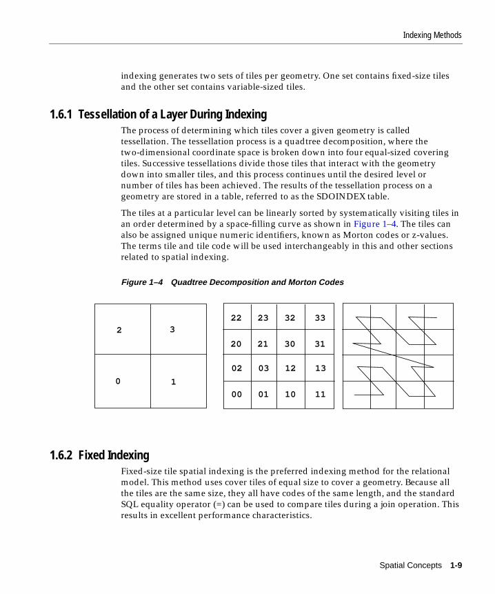
1.6.1 Tessellation of a Layer During IndexingThe process of determining which tiles cover a given geometry is calledtessellation. The tessellation process is a quadtree decomposition, where thetwo-dimensional coordinate space is broken down into four equal-sized coveringtiles. Successive tessellations divide those tiles that interact with the geometrydown into smaller tiles, and this process continues until the desired level ornumber of tiles has been achieved. The results of the tessellation process on ageometry are stored in a table, referred to as the SDOINDEX table.
The tiles at a particular level can be linearly sorted by systematically visiting tiles inan order determined by a space-filling curve as shown in Figure 1–4. The tiles canalso be assigned unique numeric identifiers, known as Morton codes or z-values.The terms tile and tile code will be used interchangeably in this and other sectionsrelated to spatial indexing.
Figure 1–4 Quadtree Decomposition and Morton Codes
1.6.2 Fixed IndexingFixed-size tile spatial indexing is the preferred indexing method for the relationalmodel. This method uses cover tiles of equal size to cover a geometry. Because allthe tiles are the same size, they all have codes of the same length, and the standardSQL equality operator (=) can be used to compare tiles during a join operation. Thisresults in excellent performance characteristics.
0 1
2 3
00 01 10 11
02 03 12 13
20 21 30 31
22 23 32 33
Spatial Concepts 1-9

Indexing Methods
Two geometries are likely to interact, and hence pass the primary filter stage, ifthey share one or more tiles. The SQL statement for the primary filter stage is:
SELECT DISTINCT <select_list for geometry identifiers> FROM table1_sdoindex A, table2_sdoindex B WHERE A.sdo_code = B.sdo_code
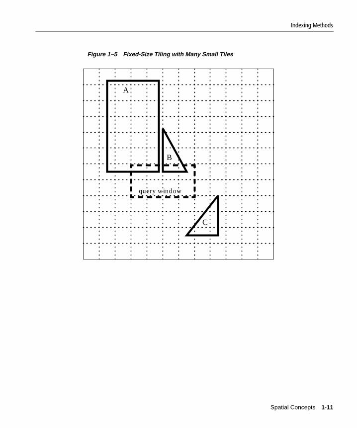
The effectiveness and efficiency of this indexing method depends on the tiling leveland the variation in size of the geometries in the layer. If you select a smallfixed-size tile to cover small geometries and then try to use the same size tile tocover a very large geometry, a large number of tiles would be required. However, ifthe chosen tile size is large, so that fewer tiles are generated in the case of a largegeometry, then the index selectivity suffers because the large tiles do notapproximate the small geometries very well. Figure 1–5 and Figure 1–6 illustratethe relationships between tile size, selectivity, and the number of cover tiles.
Using a small fixed-size tile as shown in Figure 1–5, selectivity is good, but a largenumber of tiles is needed to cover large geometries. A window query would easilyidentify geometries A and B, but would reject C.
1-10 Oracle8i Spatial User’s Guide and Reference
Indexing Methods
Figure 1–5 Fixed-Size Tiling with Many Small Tiles
A
B
query window
C
Spatial Concepts 1-11
Indexing Methods
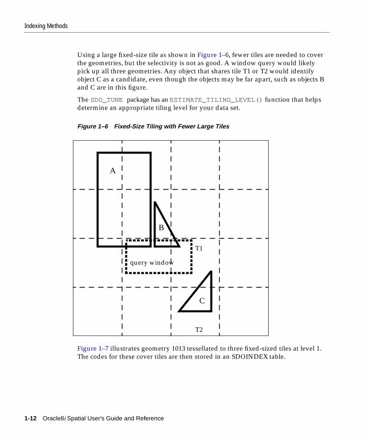
Using a large fixed-size tile as shown in Figure 1–6, fewer tiles are needed to coverthe geometries, but the selectivity is not as good. A window query would likelypick up all three geometries. Any object that shares tile T1 or T2 would identifyobject C as a candidate, even though the objects may be far apart, such as objects Band C are in this figure.
The SDO_TUNEpackage has anESTIMATE_TILING_LEVEL() function that helpsdetermine an appropriate tiling level for your data set.
Figure 1–6 Fixed-Size Tiling with Fewer Large Tiles
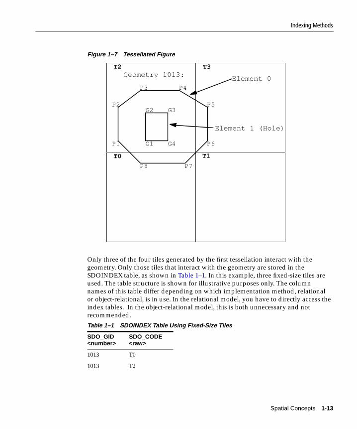
Figure 1–7 illustrates geometry 1013 tessellated to three fixed-sized tiles at level 1.The codes for these cover tiles are then stored in an SDOINDEX table.
A
B
C
T1
T2
query window
1-12 Oracle8i Spatial User’s Guide and Reference
Indexing Methods
Figure 1–7 Tessellated Figure
Only three of the four tiles generated by the first tessellation interact with thegeometry. Only those tiles that interact with the geometry are stored in theSDOINDEX table, as shown in Table 1–1. In this example, three fixed-size tiles areused. The table structure is shown for illustrative purposes only. The columnnames of this table differ depending on which implementation method, relationalor object-relational, is in use. In the relational model, you have to directly access theindex tables. In the object-relational model, this is both unnecessary and notrecommended.
Table 1–1 SDOINDEX Table Using Fixed-Size Tiles
SDO_GID<number>
SDO_CODE<raw>
1013 T0
1013 T2
G2 G3
G4G1
P3 P4
P5
P6
P7P8
P1
P2
T2 T3
T0
Geometry 1013:Element 0
Element 1 (Hole)
T1
Spatial Concepts 1-13

Indexing Methods
All elements in a geometry are tessellated. In a multielement geometry like 1013,Element 1 is already covered by tile T2 from the tessellation of Element 0. If,however, the specified tiling resolution were such that tile T2 were furthersubdivided and one of these smaller tiles were completely contained in Element 1then that tile would be excluded because it would not interact with the geometry.
1.6.3 Hybrid IndexingHybrid indexing is the preferred method for indexing the object-relational model.Hybrid indexing uses a combination of fixed- and variable-sized tiles for spatiallyindexing a layer. Variable-sized tile spatial indexing uses tiles of different sizes toapproximate a geometry. For each geometry, you will have a set of fixed-size tilesthat fully cover the geometry, and a set of variable-sized tiles that fully cover thegeometry.
In Figure 1–8, the variable-sized cover tiles closely approximate each geometry.This results in good selectivity. The number of variable tiles needed to cover ageometry is controlled using the SDO_NUMTILES parameter.
1013 T3
Table 1–1 SDOINDEX Table Using Fixed-Size Tiles(Cont.)
SDO_GID<number>
SDO_CODE<raw>
1-14 Oracle8i Spatial User’s Guide and Reference

Indexing Methods
Figure 1–8 Variable-Sized Tile Spatial Indexing
A variable tile is subdivided if it interacts with the geometry, and subdivision willnot result in tiles that are smaller than a predetermined size. This size, or tilingresolution, is determined by a default SDO_MAXLEVEL parameter. A user maymodify this parameter, but it is not recommended.
Figure 1–9 illustrates how geometry OBJ_1, represented using the object-relationalimplementation, is approximated with hybrid indexing (SDO_LEVEL = 1 andSDO_NUMTILES = 4). These are not recommended values for SDO_LEVEL andSDO_NUMTILES; they were chosen to simplify this example. The cover tiles arestored in the SDOINDEX table as shown in Table 1–2. Note that the tiles have beennumbered for simplicity and do not reflect the format used in Spatial.
A
B
C
Spatial Concepts 1-15

Indexing Methods
Figure 1–9 Decomposition of the Geometry
In Figure 1–9, note which fixed-size tiles are associated with geometry OBJ_1. Onlythree (T0, T2, T3) of the four large tiles (T0, T1, T2, T3) generated by the tessellationactually interact with the geometry. Only those are stored in the SDOINDEX table.In examining which variable sized tiles are used, tile T0 shows a further tessellationto four smaller tiles, two of which (T02, T03) are used to cover a portion of thegeometry. The variable-sized tiles are stored in the SDO_CODE column in theSpatial index table. The fixed-size tiles are stored in the SDO_GROUPCODEcolumn. The spatial index structure is discussed in Section 2.4.
G4 G3
G2G1
P7 P6
P5
P4
P3P2
P1
P8
T2 T3
T0
Geometry OBJ_1:Element 0
Element 1 (Hole)
T2_UR T3_UR
T0_UR
T0_LL
T2_LL
T3_LL
T00 T01
T02 T03
T1
1-16 Oracle8i Spatial User’s Guide and Reference

Spatial Relations and Filtering
Table 1–2 Section of the SDOINDEX Table
As with the fixed-size tile model, all elements in a geometry are tessellated in onestep. In a multielement geometry like OBJ_1, Element 1 is covered by a redundanttile from the tessellation of Element 0 but the tile, T2, is stored only once.
The SDO_TUNE package has some functions that help determine appropriateSDO_LEVEL and SDO_NUMTILES values. Appendix A contains suggestions onwhen hybrid indexing may be beneficial, and how to select values for the tworequired parameters.
1.7 Spatial Relations and FilteringSpatial uses filter methods to determine the spatial relationship between entities inthe database. The spatial relation is based on geometry locations. The mostcommon spatial relations are based on topology and distance. For example, theboundary of an area consists of a set of curves that separate the area from the restof the coordinate space. The interior of an area consists of all points in the area thatare not on its boundary. Given this, two areas are said to be adjacent if they sharepart of a boundary but no points in their interior. Next, the distance between twospatial objects is the minimum distance between any points in them. Two objectsare said to be within a given distance of one another if their distance is less than thegiven distance.
Spatial has two secondary filter methods. One method evaluates topologicalcriteria and a second method determines if two spatial objects are within aEuclidean distance of each other. The secondary filter that evaluates topologicalcriteria is called RELATE. The syntax is given in subsequent chapters that describegeometry functions and operators. RELATE implements a 9-intersection model forcategorizing binary topological relations between points, lines, and polygons.
SDO_ROWID<RAW>
SDO_CODE<RAW>
SDO_MAXCODE<RAW>
SDO_GROUPCODE<RAW>
SDO_META<RAW>
GID_OBJ_1 T02 <binary data> T0 <binary data>
GID_OBJ_1 T03 <binary data> T0 <binary data>
GID_OBJ_1 T2 <binary data> T2 <binary data>
GID_OBJ_1 T3 <binary data> T3 <binary data>
Spatial Concepts 1-17

Spatial Relations and Filtering
Each spatial object has an interior, a boundary, and an exterior. The boundaryconsists of points or lines that separate the interior from the exterior. The boundaryof a line consists of its end-points. The boundary of a polygon is the line thatdescribes its perimeter. The interior consists of points that are in the object but noton its boundary and the exterior consists of those points that are not in the object.
Given that an object A has three components -- a boundary Ab, an interior Ai, andan exterior Ae, any pair of objects will have nine possible interactions between theircomponents. Pairs of components will have an empty (0), or a non-empty (1) setintersection. The set of interactions between two geometries is represented by a9-intersection matrix that specifies which pairs of components intersect and whichdo not. Figure 1–10 shows the 9-intersection matrix for two polygons that areadjacent to one another. This matrix yields the following bit mask, generated inrow-major form: “101001111”.
Figure 1–10 The 9-Intersection Model
Some of the topological relationships identified in the seminal work by Dr.Egenhofer1 and colleagues have names associated with them. Spatial uses thefollowing names:
■ DISJOINT -- The boundaries and interiors do not intersect.
■ TOUCH --The boundaries intersect but the interiors do not.
■ OVERLAPBDYDISJOINT --The interior of one object intersects the boundaryand interior of the other object but the two boundaries do not intersect. This
1 Dr. Max Egenhofer, University of Maine, Orono.
AB
A Touch B The 9-intersection matrix
i
e
eib
b 1 0 1
0 0 1
1 1 1
A
B
1-18 Oracle8i Spatial User’s Guide and Reference
Spatial Relations and Filtering
relation occurs, for example, when a line originates outside a polygon and endsinside that polygon.
■ OVERLAPBDYINTERSECT -- The boundaries and interiors of the two objectsintersect.
■ EQUAL -- The two objects have the same boundary and interior.
■ CONTAINS -- The interior and boundary of one object is completelycontained in the interior of the other.
■ COVERS --The interior of one object is completely contained in the interior ofthe other and their boundaries intersect.
■ INSIDE -- The opposite of CONTAINS. A INSIDE B implies B CONTAINS A.
■ COVEREDBY -- The opposite of COVERS. A COVEREDBY B impliesB COVERS A
■ ANYINTERACT -- The objects are non-disjoint.
The other secondary filter, WITHIN_DISTANCE, determines if two spatial objects,A and B, are within a Euclidean distance of one another. First it constructs adistance buffer, Db, around the reference object B. It then checks that A and Db arenon-disjoint.The distance buffer of an object consists of all points within the givendistance from that object. Figure 1–11 shows the distance buffers for point, line, andarea objects. Notice how the buffer is rounded near the corners of the objects.
Spatial Concepts 1-19

Partitioned Point Data
Figure 1–11 Distance Buffers for Points, Lines, and Polygons
1.8 Partitioned Point DataPoint data, unlike line and polygon data, has the unique characteristic of alwaysusing only one tile per point. There are cases where this difference can be exploited.
Spatial has an enhanced spatial indexing mechanism capable of handling verylarge data sets consisting of complex geometries. For applications handling pointdata sets that are several tens of gigabytes or larger, further performance gains canbe achieved by using Oracle8i table partitioning features.
Table partitioning is available only with the Partitioning Option of Oracle8iEnterprise Edition. If the Partitioning Option is available to you, the preferredmethod is to use Oracle8i table partitioning in conjunction with spatial indexing(using the relational model). See the Oracle8i Concepts guide for a description ofOracle8i Partitioning. See Section A.2.6.3 for a description of a sample script thatuses table partitioning with point data.
A previous release of Spatial Data Option (from which the current Spatial producthas evolved) utilized its own version of table partitioning instead of spatialindexing. Appendix C briefly describes the deprecated partitioning scheme forthose customers with legacy point data sets. While this feature is still enabled in thecurrent release, it may be removed in the future.
1-20 Oracle8i Spatial User’s Guide and Reference

Part I
Object-Relational ModelOracle8i Spatial supports two models for representing geometries: relational andobject-relational. The two models are mutually exclusive. See Section A.1 for adescription of how to choose the model best suited for your application.
You do not need prior knowledge of the relational model to use the newobject-relational model.
This part of the User’s Guide and Reference contains the following chapters,describing the object-relational model:
■ Chapter 2, "The Object-Relational Schema"
■ Chapter 3, "Loading and Indexing Spatial Object Types"
■ Chapter 4, "Querying Spatial Data"
■ Chapter 5, "Indexing Statements for Object Relational Model"
■ Chapter 6, "Tuning Functions and Procedures for Object-Relational Model"
■ Chapter 7, "Geometry Functions for Object-Relational Model"
■ Chapter 8, "Migration Procedures"
■ Chapter 9, "Spatial Operators"


The Object-Relational S
2
The Object-Relational SchemaThe object-relational implementation of Oracle8i Spatial consists of a set of objectdata types, an index method type, and operators on these types. A geometry isstored as an object, in a single row, in a column of type SDO_GEOMETRY. Spatialindex creation and maintenance is done using basic DDL (CREATE, ALTER,DROP) and DML (INSERT, UPDATE, DELETE) statements.
2.1 Object-Relational Data StructuresIn the Spatial object-relational model, a single SDO_GEOMETRY object replaces therows and columns in a <layername>_SDOGEOM table of the relational model.
The geometric description of a spatial object is stored in a single row, in a singlecolumn of object type SDO_GEOMETRY in a user-defined table. The table does notrequire the "_SDOGEOM" suffix anymore. Because the SDO_GEOMETRY typedoes not have an SDO_GID attribute, any table that has a column of type SDO_GEOMETRY must have another column, or set of columns, that defines a uniqueprimary key for that table. Tables of this sort are sometimes referred to as geometrytables.
Oracle8i Spatial defines the object type SDO_GEOMETRY as:
CREATE TYPE sdo_geometry AS OBJECT ( SDO_GTYPE NUMBER, SDO_SRID NUMBER, SDO_POINT SDO_POINT_TYPE, SDO_ELEM_INFO MDSYS.SDO_ELEM_INFO_ARRAY, SDO_ORDINATES MDSYS.SDO_ORDINATE_ARRAY);
chema 2-1
Object-Relational Data Structures
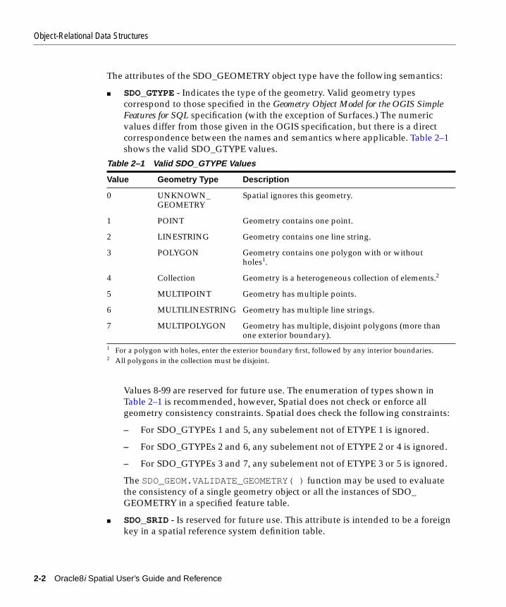
The attributes of the SDO_GEOMETRY object type have the following semantics:
■ SDO_GTYPE - Indicates the type of the geometry. Valid geometry typescorrespond to those specified in the Geometry Object Model for the OGIS SimpleFeatures for SQL specification (with the exception of Surfaces.) The numericvalues differ from those given in the OGIS specification, but there is a directcorrespondence between the names and semantics where applicable. Table 2–1shows the valid SDO_GTYPE values.
Values 8-99 are reserved for future use. The enumeration of types shown inTable 2–1 is recommended, however, Spatial does not check or enforce allgeometry consistency constraints. Spatial does check the following constraints:
– For SDO_GTYPEs 1 and 5, any subelement not of ETYPE 1 is ignored.
– For SDO_GTYPEs 2 and 6, any subelement not of ETYPE 2 or 4 is ignored.
– For SDO_GTYPEs 3 and 7, any subelement not of ETYPE 3 or 5 is ignored.
The SDO_GEOM.VALIDATE_GEOMETRY( ) function may be used to evaluatethe consistency of a single geometry object or all the instances of SDO_GEOMETRY in a specified feature table.
■ SDO_SRID- Is reserved for future use. This attribute is intended to be a foreignkey in a spatial reference system definition table.
1 For a polygon with holes, enter the exterior boundary first, followed by any interior boundaries.2 All polygons in the collection must be disjoint.
Table 2–1 Valid SDO_GTYPE Values
Value Geometry Type Description
0 UNKNOWN_GEOMETRY
Spatial ignores this geometry.
1 POINT Geometry contains one point.
2 LINESTRING Geometry contains one line string.
3 POLYGON Geometry contains one polygon with or withoutholes1.
4 Collection Geometry is a heterogeneous collection of elements.2
5 MULTIPOINT Geometry has multiple points.
6 MULTILINESTRING Geometry has multiple line strings.
7 MULTIPOLYGON Geometry has multiple, disjoint polygons (more thanone exterior boundary).
2-2 Oracle8i Spatial User’s Guide and Reference

Object-Relational Data Structures
■ SDO_POINT - Is an object type with attributes X, Y, and Z, all of type NUMBER.If the SDO_ELEM_INFO and SDO_ORDINATES arrays are both null, and theSDO_POINT attribute is non-null, then the X and Y values are considered to bethe coordinates for a point geometry. Otherwise the SDO_POINT attribute isignored by Spatial. You should store points in the SDO_POINT attribute foroptimal storage.
■ SDO_ELEM_INFO - Is a varying length array of numbers. This attribute lets youknow how to interpret the ordinates stored in the SDO_ORDINATES attribute.
Each triplet set of numbers conveys information about one geometry element,and a geometry may contain many elements. If a geometry has one element,then the SDO_ELEM_INFO array has three numbers; if the geometry has twoelements, then the array has six numbers, and so on. Each triplet set isinterpreted as follows:
1. SDO_STARTING_OFFSET -- Indicates the offset within the SDO_ORDINATES array where the first ordinate for this element is stored.Offset values start at 1 and not at 0. Thus the first ordinate for the firstelement will be at SDO_GEOMETRY.SDO_ORDINATES(1).
2. SDO_ETYPE - Indicates the type of the element. Valid values are 0 through5.
SDO_ETYPEs 1, 2, and 3, are considered simple elements. They are definedby a single triplet entry in the SDO_ELEMINFO array. SDO_ETYPEs 4 and5 are considered compound elements. They contain at least one headertriplet with a series of triplet values that belong to the compound element.
The elements of a compound element are contiguous. The last point of asubelement in a compound element is the first point of the nextsubelement. The point is not repeated.
3. SDO_INTERPRETATION - Means one of two things, depending onwhether or not SDO_ETYPE is a compound element.
If SDO_ETYPE is a compound element (4 or 5), this field specifies howmany subsequent triplet values are part of the element.
If the SDO_ETYPE is not a compound element (1, 2, or 3), the interpretationattribute determines how the sequence of ordinates for this element isinterpreted. For example, a line string or polygon boundary may be madeup of a sequence of connected straight line segments or circular arcs.
A description of valid SDO_ETYPE and SDO_INTERPRETATION valuepairs is given in Table 2–2.
The Object-Relational Schema 2-3

Object-Relational Data Structures
If a geometry consists of more than one element, then the last ordinate for anelement is always one less than the starting offset for the next element. The lastelement in the geometry is described by the ordinates from its starting offset tothe end of the SDO_ORDINATES varying length array.
For compound elements (SDO_ETYPEs 4 and 5), a set of N triplets (one persubelement) is used to describe the element. It is important to remember thatsubelements of a compound element are contiguous. The last point of asubelement is the first point of the next subelement. For subelements 1 throughN-1, the end point of one subelement is the same as the starting point of thenext subelement. The starting point for subelements 2...N-2 is the same as theend point of subelement 1...N-1. The last ordinate of subelement N is either thestarting offset-1 of the next element in the geometry, or the last ordinate in theSDO_ORDINATES varying length array.
The current size of a varying length array can be determined by using thefunction varray_variable.Count( ) in PL/SQL or OCIColSize( ) in Oracle CallInterface (OCI).
The semantics of each SDO_ETYPE element and the relationship between theSDO_ELEM_INFO and SDO_ORDINATES varying length arrays for each ofthese SDO_ETYPE elements is given in Table 2–2.
Table 2–2 Values and Semantics in SDO_ELEM_INFO
SDO_ETYPE
SDO_INTERPRETATION Meaning
0 0 Unsupported element type. Ignored by the Spatial functionsand procedures.
1 1 Point type.
1 N > 1 Point cluster with N points.
2 1 Line string whose vertices are connected by straight linesegments.
2 2 Line string made up of a connected sequence of circular arcs.
Each circular arc is described using three coordinates: thearc’s starting point, any point on the arc, and the arc’s endpoint. The coordinates for a point designating the end of onearc and the start of the next arc are not repeated. Forexample, five coordinates are used to describe a line stringmade up of two connected circular arcs. Points 1, 2, and 3define the first arc, and points 3, 4, and 5 define the secondarc, where point 3 is only stored once.
2-4 Oracle8i Spatial User’s Guide and Reference
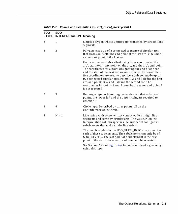
Object-Relational Data Structures
3 1 Simple polygon whose vertices are connected by straight linesegments.
3 2 Polygon made up of a connected sequence of circular arcsthat closes on itself. The end point of the last arc is the sameas the start point of the first arc.
Each circular arc is described using three coordinates: thearc’s start point, any point on the arc, and the arc’s end point.The coordinates for a point designating the end of one arcand the start of the next arc are not repeated. For example,five coordinates are used to describe a polygon made up oftwo connected circular arcs. Points 1, 2, and 3 define the firstarc, and points 3, 4, and 5 define the second arc. Thecoordinates for points 1 and 5 must be the same, and point 3is not repeated.
3 3 Rectangle type. A bounding rectangle such that only twopoints, the lower-left and the upper-right, are required todescribe it.
3 4 Circle type. Described by three points, all on thecircumference of the circle.
4 N > 1 Line string with some vertices connected by straight linesegments and some by circular arcs. The value, N, in theInterpretation column specifies the number of contiguoussubelements that make up the line string.
The next N triplets in the SDO_ELEM_INFO array describeeach of these subelements. The subelements can only be ofSDO_ETYPE 2. The last point of a subelement is the firstpoint of the next subelement, and must not be repeated.
See Section 2.2 and Figure 2–2 for an example of a geometryusing this type.
Table 2–2 Values and Semantics in SDO_ELEM_INFO (Cont.)
SDO_ETYPE
SDO_INTERPRETATION Meaning
The Object-Relational Schema 2-5

Geometry Examples Using the Object-Relational Model
■ SDO_ORDINATES - Is a varying length array (1048576) of NUMBER type thatstores the coordinate values that make up the boundary of a spatial object. Thisarray must always be used in conjunction with the SDO_ELEM_INFO varyinglength array. The values in the array are ordered by dimension. For example, apolygon, whose boundary has four 2-dimensional points, is stored as {X1, Y1,X2, Y2, X3, Y3, X4, Y4, X1, Y1}. If the points are 3-dimensional, then they arestored as {X1, Y1, Z1, X2, Y2, Z2, X3, Y3, Z3, X4, Y4, Z4, X1, Y1, Z1}. Spatialindex creation, operators, and functions ignore the Z values because thisrelease of the product supports only 2-dimensional spatial objects. The numberof dimensions associated with each point is stored as metadata in the SDO_GEOM_METADATA table, described in Section 2.3.
The values in the SDO_ORDINATES array must all be valid and non-null.There are no special values used to delimit elements in a multi-elementgeometry. The start and end points for the sequence describing a specificelement are determined by the STARTING_OFFSET values for that elementand the next element in the SDO_ELEM_INFO array as explained previously.The offset values start at 1. SDO_ORDINATES(1) is the first ordinate of the firstpoint of the first element.
2.2 Geometry Examples Using the Object-Relational ModelFigure 2–1 illustrates a geometry with two elements. The inner element in thisexample is treated as a void (a hole).
5 N > 1 Simple polygon with some vertices connected by straightline segments and some by circular arcs. The value, N, in theInterpretation column specifies the number of contiguoussubelements that make up the polygon.
The next N triplets in the SDO_ELEM_INFO array describeeach of these subelements. The subelements can only be ofSDO_ETYPE 2. The end point of a subelement is the startpoint of the next subelement and must not be repeated. Thestart and end points of the polygon must be the same.
See Section 2.2 and Figure 2-3 for an example of a geometryusing this type.
Table 2–2 Values and Semantics in SDO_ELEM_INFO (Cont.)
SDO_ETYPE
SDO_INTERPRETATION Meaning
2-6 Oracle8i Spatial User’s Guide and Reference

Geometry Examples Using the Object-Relational Model
Figure 2–1 Geometry with a Hole
In Figure 2–2, consider a crescent-shaped object represented as a compound linestring made up of one straight line segment and one circular arc. Four points arerequired to represent this shape. Points 1 and 2 describe the straight line segmentand points 2, 3, and 4 describe the circular arc. The SDO_ELEM_INFO arraycontains 3 triplets for this compound line string. These are {(1,4,2), (1,2,1), (3,2,2)}.The SDO_ORDINATES array contains (X1,Y1, X2, Y2, X3, Y3, X4,Y4).
(12,24) (15,24)
(15,15)(12,15)
(11,40) (19,40)
(25,35)
(25,15)
(20,10)(10,10)
P1=(6,15)
P8=(6,25)
Geometry OBJ_1:
SDO_GTYPE = 3SDO_SRID = NULL
SDO_ELEM_INFO = (1,3,1,19,3,1)SDO_ORDINATES = (6,15,10,10,20,10, 25,15,25,35,19,40, 11,40,6,25,6,15, 12,15,15,15,15,24, 12,24,12,15) )
SDO_POINT = NULL
SDO_GEOMETRY Column = (
The Object-Relational Schema 2-7

Geometry Examples Using the Object-Relational Model
Figure 2–2 Compound Element
The first triplet indicates that this element is a compound line string made up oftwo line strings, which are described with the next two triplets.
The second triplet indicates that the line string is made up of straight line segmentsand that the ordinates for this line string start at offset 1. The end point of this linestring is determined by the starting offset of the second line string, 3 in thisinstance. Assuming the vertices are 2-dimensional, the coordinates for the endpoint of the first line string are at ordinates 3 and 4.
The third triplet indicates that the second line string is made up of circular arcswith ordinates starting at offset 3. The end point of this line string is determined bythe starting offset of the next element or the current length of the SDO_ORDINATES array, if this is the last element.
In Figure 2-3, consider an ice cream cone shaped object represented as a compoundpolygon made up of one straight line segment and one circular arc. Five points arerequired to represent this shape. Points 1, 2, and 3 describe one acute angle shapedline string, and points 3, 4, and 5 describe the circular arc. Points 1 and 5 are thesame point. The SDO_ELEM_INFO array contains three triplets for this compoundline string. These triplets are {(1,5,2), (1,2,1), (5,2,2)}.
x1,y1
x2,y2
x3,y3
x4,y41
2
3
4
NU-3746A-AI
2-8 Oracle8i Spatial User’s Guide and Reference

Geometry Metadata Structure
Figure 2–3 Compound Polygon
The first triplet indicates that this element is a compound line string made up oftwo line strings, which are described using the next two triplets.
The second triplet indicates that the line string is made up of straight line segmentsand that the ordinates for this line string start at offset 1. The end point of this linestring is determined by the starting offset of the second line string, 5 in thisinstance. Assuming the vertices are 2-dimensional, the coordinates for the endpoint of the first line string are at ordinates 5 and 6.
The third triplet indicates that the second line string is made up of circular arcswith ordinates starting at offset 5. The end point of this line string is determined bythe starting offset of the next element or the current length of the SDO_ORDINATES array, if this is the last element.
2.3 Geometry Metadata StructureThe geometry metadata describing the dimensions, lower and upper bounds, andtolerance in each dimension must be stored as a single entry in a table named SDO_GEOM_METADATA created in your schema and defined as follows:
Create Table SDO_GEOM_METADATA ( TABLE_NAME VARCHAR2(30), COLUMN_NAME VARCHAR2(30), DIMINFO MDSYS.SDO_DIM_ARRAY);
x1,y1x5,y5
x4,y4
x3,y3
x2,y2
1,5
2
3
4
NU-3747A-AI
The Object-Relational Schema 2-9
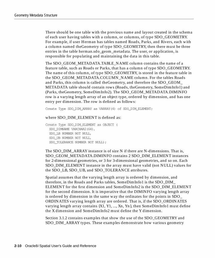
Geometry Metadata Structure
There should be one table with the previous name and layout created in the schemaof each user having tables with a column, or columns, of type SDO_GEOMETRY.For example, if user Herman has tables named Roads, Parks, and Rivers, each witha column named theGeometry of type SDO_GEOMETRY, then there must be threeentries in the table herman.sdo_geom_metadata. The user, or application, isresponsible for populating and maintaining the data in this table.
The SDO_GEOM_METADATA.TABLE_NAME column contains the name of afeature table, such as Roads or Parks, that has a column of type SDO_GEOMETRY.The name of this column, of type SDO_GEOMETRY, is stored in the feature table inthe SDO_GEOM_METADATA.COLUMN_NAME column. For the tables Roadsand Parks, this column is called theGeometry, and therefore the SDO_GEOM_METADATA table should contain rows (Roads, theGeometry, SomeDimInfo1) and(Parks, theGeometry, SomeDimInfo2). The SDO_GEOM_METADATA.DIMINFOrow is a varying length array of an object type, ordered by dimension, and has oneentry per dimension. The row is defined as follows:
Create Type SDO_DIM_ARRAY as VARRAY(4) of SDO_DIM_ELEMENT;
where SDO_DIM_ELEMENT is defined as:
Create Type SDO_DIM_ELEMENT as OBJECT ( SDO_DIMNAME VARCHAR2(64), SDO_LB NUMBER NOT NULL, SDO_UB NUMBER NOT NULL, SDO_TOLERANCE NUMBER NOT NULL);
The SDO_DIM_ARRAY instance is of size N if there are N-dimensions. That is,SDO_GEOM_METADATA.DIMINFO contains 2 SDO_DIM_ELEMENT instancesfor 2-dimensional geometries, or 3 for 3-dimensional geometries, and so on. EachSDO_DIM_ELEMENT instance in the array must have valid (not NULL) values forthe SDO_LB, SDO_UB, and SDO_TOLERANCE attributes.
Spatial assumes that the varying length array is ordered by dimension, andtherefore, in the Roads and Parks tables, SomeDimInfo1 is the SDO_DIM_ELEMENT for the first dimension and SomeDimInfo2 is the SDO_DIM_ELEMENTfor the second dimension. It is imperative that the DIMINFO varying length arrayis ordered by dimension in the same way the ordinates for the points in SDO_ORDINATES varying length array are ordered. That is, if the SDO_ORDINATESvarying length array contains {X1, Y1, ..., Xn, Yn}, then SomeDimInfo1 must definethe X dimension and SomeDimInfo2 must define the Y dimension.
Section 3.1.2 contains examples that show the use of the SDO_GEOMETRY andSDO_DIM_ARRAY types. These examples demonstrate how various geometry
2-10 Oracle8i Spatial User’s Guide and Reference

Spatial Index-Related Structure
objects are represented, and how a feature table and the SDO_GEOM_METADATAtable are populated with the data for those objects.
2.4 Spatial Index-Related StructureThis section describes the structure of the tables containing the spatial index dataand metadata. Concepts and usage notes for spatial indexing are explained inSection 1.6. Both the spatial index data and metadata are stored in tables createdand maintained by the spatial indexing routines. These tables are created in thesame schema as the owner of the feature (underlying) table with a spatial indexcreated on a column of type SDO_GEOMETRY.
2.4.1 Spatial Index TablesThere is one metadata view per schema (user), named SDO_INDEX_METADATA,and one index data table per spatially indexed column in that schema. Thus if userHerman has five feature tables, each with a spatial index on their respective SDO_GEOMETRY typed column, then Herman’s schema has one SDO_INDEX_METADATA view and five tables containing spatial index data. The index datatable names are not created by adding the " _SDOINDEX" suffix to the layer name.Instead, the index data table is named using the user-specified index name and asuffix that indicates the spatial index type (fixed or hybrid, as defined inSection 1.6) and the values of the relevant index parameters.
The SDO_INDEX_METADATA view contains the following columns whose typeand purpose are shown in Table 2–3.
Table 2–3 Columns in an SDO_INDEX_METADATA View
Column Name Data Type Purpose
SDO_LEVEL NUMBER The fixed tiling level at which to tile all objectsin the feature table.
SDO_NUMTILES NUMBER Suggested number of tiles per object thatshould be used to approximate the shape.
SDO_MAXLEVEL NUMBER The maximum level for any tile for any object.It will always be greater than the SDO_LEVELvalue.
SDO_COMMIT_INTERVAL NUMBER The number of geometries (rows) to process,during index creation, before committing theinsertion of spatial index entries into theSDOINDEX table. See Appendix A for adiscussion of the use of this parameter.
The Object-Relational Schema 2-11

Spatial Index-Related Structure
2.4.2 Spatial Index Data Dictionary ViewThe index data table will have some or all of the columns shown in Table 2–4.
SDO_INDEX_TABLE VARCHAR2 Name of the SDOINDEX table.
SDO_TABLESPACE VARCHAR2 Same as in the basic SQL CREATE TABLEstatement. Tablespace in which to create theSDOINDEX table.
SDO_INITIAL_EXTENT NUMBER Same as in SQL CREATE TABLE statement.
SDO_NEXT_EXTENT NUMBER Same as in SQL CREATE TABLE statement.
SDO_PCTINCREASE NUMBER Same as in SQL CREATE TABLE statement.
SDO_MIN_EXTENTS NUMBER Same as in SQL CREATE TABLE statement.
SDO_MAX_EXTENTS NUMBER Same as in SQL CREATE TABLE statement.
SDO_FIXED_METADATA RAW If applicable, this column contains themetadata portion of the SDO_GROUPCODE orSDO_CODE for a fixed-level index.
SDO_INDEX_COORDSYS VARCHAR2 Reserved for future use.
SDO_INDEX_PRIMARY NUMBER Indicates if this is a primary or secondaryindex. 1 = primary, 2 = secondary.
SDO_INDEX_OWNER VARCHAR2 The owner of the index.
SDO_INDEX_NAME VARCHAR2 The name of the index.
SDO_TSNAME VARCHAR2 The schema name of the SDO_INDEX_TABLE.
SDO_COLUMN_NAME VARCHAR2 The column name on which this index is built.
Table 2–4 Columns in a Spatial Index Data Table
Column Name Data Type Purpose
SDO_ROWID RAW Row ID of a row in a feature table containing theindexed object.
SDO_CODE RAW Index entry for the object in the row identified by SDO_ROWID.
SDO_MAXCODE RAW Padded SDO_CODE column.
SDO_GROUPCODE RAW Index entry at level SDO_LEVEL.
Table 2–3 Columns in an SDO_INDEX_METADATA View (Cont.)
Column Name Data Type Purpose
2-12 Oracle8i Spatial User’s Guide and Reference
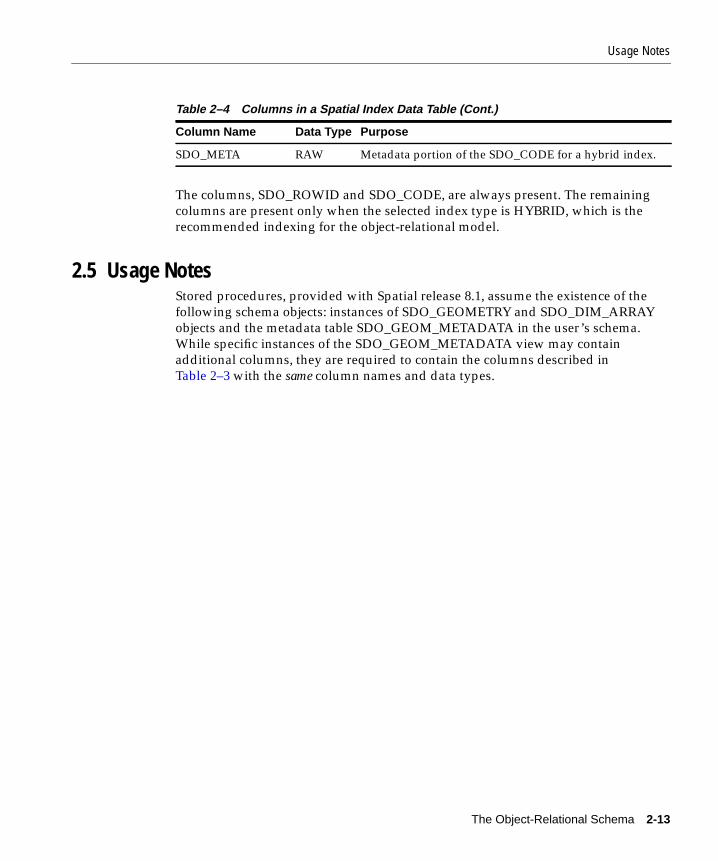
Usage Notes
The columns, SDO_ROWID and SDO_CODE, are always present. The remainingcolumns are present only when the selected index type is HYBRID, which is therecommended indexing for the object-relational model.
2.5 Usage NotesStored procedures, provided with Spatial release 8.1, assume the existence of thefollowing schema objects: instances of SDO_GEOMETRY and SDO_DIM_ARRAYobjects and the metadata table SDO_GEOM_METADATA in the user’s schema.While specific instances of the SDO_GEOM_METADATA view may containadditional columns, they are required to contain the columns described inTable 2–3 with the same column names and data types.
SDO_META RAW Metadata portion of the SDO_CODE for a hybrid index.
Table 2–4 Columns in a Spatial Index Data Table (Cont.)
Column Name Data Type Purpose
The Object-Relational Schema 2-13

Usage Notes
2-14 Oracle8i Spatial User’s Guide and Reference

Loading and Indexing Spatial Objec
3
Loading and Indexing Spatial Object TypesThis chapter describes how to load spatial data into a database, including storingthe data in a table with a column of type SDO_GEOMETRY and creating a spatialindex for it.
The following steps will enable you to efficiently query spatial data:
1. Load data into column of type SDO_GEOMETRY
2. Create spatial indexes on columns of type SDO_GEOMETRY
3.1 Load ProcessThe process of loading data can be classified into two categories:
■ Bulk loading of data
This process is used to load large volumes of data into the database and usesSQL*Loader1 utility to load the data.
■ Transactional inserts
This process is used to insert relatively small amounts of data into the databaseusing the INSERT statement in SQL.
3.1.1 Bulk LoadingBulk loading can import large amounts of ASCII data into an Oracle database. Bulkloading is accomplished with the SQL*Loader utility.
1 See Oracle8i Utilities for information on SQL*Loader.
t Types 3-1

Load Process
3.1.1.1 Bulk Loading the SDO_GEOMETRY ObjectThe following example assumes a table called POLY_4PT was created as follows:
CREATE TABLE POLY_4PT (GID VARCHAR2(32) GEOMETRY MDSYS.SDO_GEOMETRY);
Assume that the ASCII data consists of a file with delimited columns and separaterows fixed by the limits of the table with the following format:
geometry rows: GID, GEOMETRY
The coordinates in the geometry column represent roads for a region. Example 3–1shows the control file for loading the roads and attributes.
Example 3–1 Control File for a Bulk Load
LOAD DATA INFILE *INTO TABLE POLY_4PTREPLACEFIELDS TERMINATED BY ',' OPTIONALLY ENCLOSED BY '"'TRAILING NULLCOLS(gid char(6),geometry COLUMN OBJECT( sdo_gtype INTEGER EXTERNAL, sdo_srid INTEGER EXTERNAL, isnull FILLER CHAR, SDO_POINT COLUMN OBJECT NULLIF geometry.isnull="pt" ( X INTEGER EXTERNAL, Y INTEGER EXTERNAL, Z INTEGER EXTERNAL), SDO_ELEM_INFO VARRAY terminated by ';' (SDO_ORDINATES char(38)), SDO_ORDINATES VARRAY terminated by ':' (SDO_ORDINATES char(38))))begindata1,3,,pt,,,,1,3,1; -122.4215,37.7862, -122.422,37.7869, -122.421,37.789,-122.42,37.7866, -122.4215,37.7862:2,3,,pt,,,,1,3,1; -122.4019,37.8052, -122.4027,37.8055, -122.4031,37.806,-122.4012,37.8052, -122.4019,37.8052:3,3,,pt,,,,1,3,1; -122.426,37.803, -122.4242,37.8053, -122.42355,37.8044,-122.4235,37.8025, -122.426,37.803:
3-2 Oracle8i Spatial User’s Guide and Reference
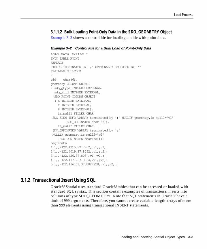
Load Process
3.1.1.2 Bulk Loading Point-Only Data in the SDO_GEOMETRY ObjectExample 3–2 shows a control file for loading a table with point data.
Example 3–2 Control File for a Bulk Load of Point-Only Data
LOAD DATA INFILE *INTO TABLE POINTREPLACEFIELDS TERMINATED BY ',' OPTIONALLY ENCLOSED BY '"'TRAILING NULLCOLS(gid char(6),geometry COLUMN OBJECT( sdo_gtype INTEGER EXTERNAL, sdo_srid INTEGER EXTERNAL, SDO_POINT COLUMN OBJECT ( X INTEGER EXTERNAL, Y INTEGER EXTERNAL, Z INTEGER EXTERNAL), is_null1 FILLER CHAR, SDO_ELEM_INFO VARRAY terminated by ';' NULLIF geometry.is_null1="v1" (SDO_ORDINATES char(38)), is_null2 FILLER CHAR, SDO_ORDINATES VARRAY terminated by ':' NULLIF geometry.is_null2="v2" (SDO_ORDINATES char(38))))begindata1,1,,-122.4215,37.7862,,v1,;v2,:2,1,,-122.4019,37.8052,,v1,;v2,:3,1,,-122.426,37.803,,v1,;v2,:4,1,,-122.4171,37.8034,,v1,;v2,:5,1,,-122.416151,37.8027228,,v1,;v2,:
3.1.2 Transactional Insert Using SQLOracle8i Spatial uses standard Oracle8i tables that can be accessed or loaded withstandard SQL syntax. This section contains examples of transactional inserts intocolumns of type SDO_GEOMETRY. Note that SQL statements in Oracle8i have alimit of 999 arguments. Therefore, you cannot create variable-length arrays of morethan 999 elements using transactional INSERT statements.
Loading and Indexing Spatial Object Types 3-3
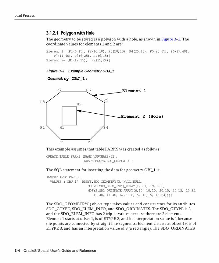
Load Process
3.1.2.1 Polygon with HoleThe geometry to be stored is a polygon with a hole, as shown in Figure 3–1. Thecoordinate values for elements 1 and 2 are:
Element 1= [P1(6,15), P2(10,10), P3(20,10), P4(25,15), P5(25,35), P6(19,40), P7(11,40), P8(6,25), P1(6,15)]Element 2= [H1(12,15), H2(15,24)]
Figure 3–1 Example Geometry OBJ_1
This example assumes that table PARKS was created as follows:
CREATE TABLE PARKS (NAME VARCHAR2(32), SHAPE MDSYS.SDO_GEOMETRY);
The SQL statement for inserting the data for geometry OBJ_1 is:
INSERT INTO PARKS VALUES (’OBJ_1’, MDSYS.SDO_GEOMETRY(3, NULL,NULL, MDSYS.SDO_ELEM_INFO_ARRAY(1,3,1, 19,3,3), MDSYS.SDO_ORDINATE_ARRAY(6,15, 10,10, 20,10, 25,15, 25,35, 19,40, 11,40, 6,25, 6,15, 12,15, 15,24)));
The SDO_GEOMETRY( ) object type takes values and constructors for its attributesSDO_GTYPE, SDO_ELEM_INFO, and SDO_ORDINATES. The SDO_GTYPE is 3,and the SDO_ELEM_INFO has 2 triplet values because there are 2 elements.Element 1 starts at offset 1, is of ETYPE 3, and its interpretation value is 1 becausethe points are connected by straight line segments. Element 2 starts at offset 19, is ofETYPE 3, and has an interpretation value of 3 (a rectangle). The SDO_ORDINATES
H2
H1
P7 P6
P5
P4
P3P2
P1
P8
Element 1
Element 2 (Hole)
Geometry OBJ_1:
3-4 Oracle8i Spatial User’s Guide and Reference
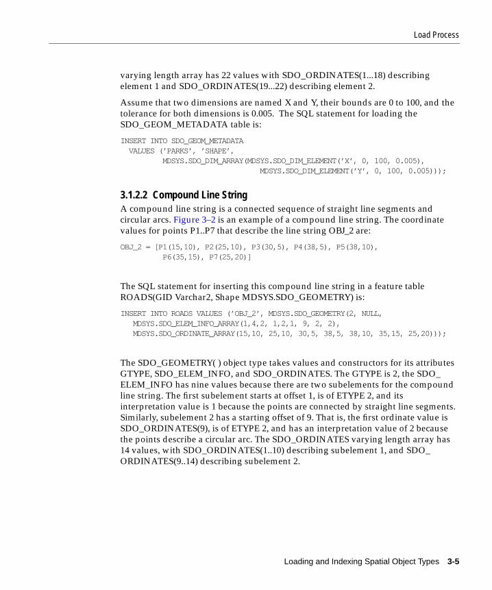
Load Process
varying length array has 22 values with SDO_ORDINATES(1...18) describingelement 1 and SDO_ORDINATES(19...22) describing element 2.
Assume that two dimensions are named X and Y, their bounds are 0 to 100, and thetolerance for both dimensions is 0.005. The SQL statement for loading theSDO_GEOM_METADATA table is:
INSERT INTO SDO_GEOM_METADATA VALUES (’PARKS’, ’SHAPE’, MDSYS.SDO_DIM_ARRAY(MDSYS.SDO_DIM_ELEMENT(’X’, 0, 100, 0.005), MDSYS.SDO_DIM_ELEMENT(’Y’, 0, 100, 0.005)));
3.1.2.2 Compound Line StringA compound line string is a connected sequence of straight line segments andcircular arcs. Figure 3–2 is an example of a compound line string. The coordinatevalues for points P1..P7 that describe the line string OBJ_2 are:
OBJ_2 = [P1(15,10), P2(25,10), P3(30,5), P4(38,5), P5(38,10), P6(35,15), P7(25,20)]
The SQL statement for inserting this compound line string in a feature tableROADS(GID Varchar2, Shape MDSYS.SDO_GEOMETRY) is:
INSERT INTO ROADS VALUES (’OBJ_2’, MDSYS.SDO_GEOMETRY(2, NULL, MDSYS.SDO_ELEM_INFO_ARRAY(1,4,2, 1,2,1, 9, 2, 2), MDSYS.SDO_ORDINATE_ARRAY(15,10, 25,10, 30,5, 38,5, 38,10, 35,15, 25,20)));
The SDO_GEOMETRY( ) object type takes values and constructors for its attributesGTYPE, SDO_ELEM_INFO, and SDO_ORDINATES. The GTYPE is 2, the SDO_ELEM_INFO has nine values because there are two subelements for the compoundline string. The first subelement starts at offset 1, is of ETYPE 2, and itsinterpretation value is 1 because the points are connected by straight line segments.Similarly, subelement 2 has a starting offset of 9. That is, the first ordinate value isSDO_ORDINATES(9), is of ETYPE 2, and has an interpretation value of 2 becausethe points describe a circular arc. The SDO_ORDINATES varying length array has14 values, with SDO_ORDINATES(1..10) describing subelement 1, and SDO_ORDINATES(9..14) describing subelement 2.
Loading and Indexing Spatial Object Types 3-5
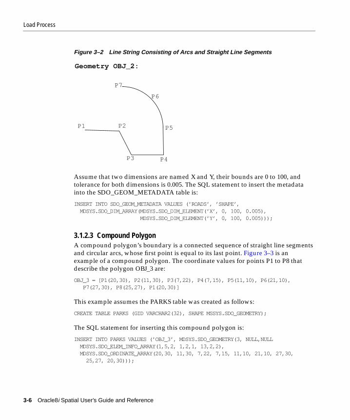
Load Process
Figure 3–2 Line String Consisting of Arcs and Straight Line Segments
Assume that two dimensions are named X and Y, their bounds are 0 to 100, andtolerance for both dimensions is 0.005. The SQL statement to insert the metadatainto the SDO_GEOM_METADATA table is:
INSERT INTO SDO_GEOM_METADATA VALUES (’ROADS’, ’SHAPE’, MDSYS.SDO_DIM_ARRAY(MDSYS.SDO_DIM_ELEMENT(’X’, 0, 100, 0.005), MDSYS.SDO_DIM_ELEMENT(’Y’, 0, 100, 0.005)));
3.1.2.3 Compound PolygonA compound polygon’s boundary is a connected sequence of straight line segmentsand circular arcs, whose first point is equal to its last point. Figure 3–3 is anexample of a compound polygon. The coordinate values for points P1 to P8 thatdescribe the polygon OBJ_3 are:
OBJ_3 = [P1(20,30), P2(11,30), P3(7,22), P4(7,15), P5(11,10), P6(21,10), P7(27,30), P8(25,27), P1(20,30)]
This example assumes the PARKS table was created as follows:
CREATE TABLE PARKS (GID VARCHAR2(32), SHAPE MSSYS.SDO_GEOMETRY);
The SQL statement for inserting this compound polygon is:
INSERT INTO PARKS VALUES (’OBJ_3’, MDSYS.SDO_GEOMETRY(3, NULL,NULL MDSYS.SDO_ELEM_INFO_ARRAY(1,5,2, 1,2,1, 13,2,2), MDSYS.SDO_ORDINATE_ARRAY(20,30, 11,30, 7,22, 7,15, 11,10, 21,10, 27,30, 25,27, 20,30)));
P7
P6
P5
P4P3
P2P1
Geometry OBJ_2:
3-6 Oracle8i Spatial User’s Guide and Reference
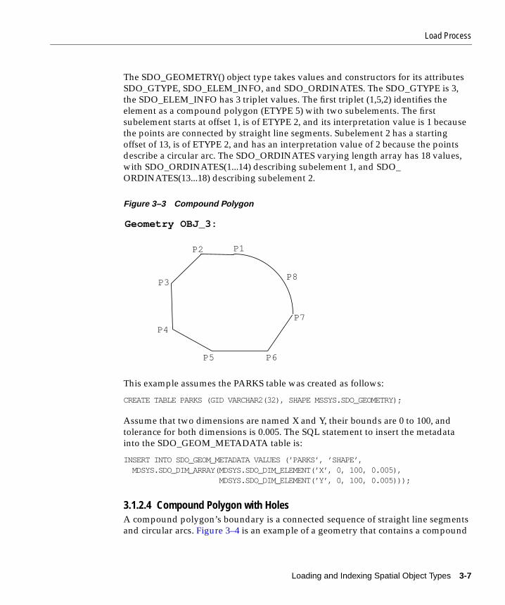
Load Process
The SDO_GEOMETRY() object type takes values and constructors for its attributesSDO_GTYPE, SDO_ELEM_INFO, and SDO_ORDINATES. The SDO_GTYPE is 3,the SDO_ELEM_INFO has 3 triplet values. The first triplet (1,5,2) identifies theelement as a compound polygon (ETYPE 5) with two subelements. The firstsubelement starts at offset 1, is of ETYPE 2, and its interpretation value is 1 becausethe points are connected by straight line segments. Subelement 2 has a startingoffset of 13, is of ETYPE 2, and has an interpretation value of 2 because the pointsdescribe a circular arc. The SDO_ORDINATES varying length array has 18 values,with SDO_ORDINATES(1...14) describing subelement 1, and SDO_ORDINATES(13...18) describing subelement 2.
Figure 3–3 Compound Polygon
This example assumes the PARKS table was created as follows:
CREATE TABLE PARKS (GID VARCHAR2(32), SHAPE MSSYS.SDO_GEOMETRY);
Assume that two dimensions are named X and Y, their bounds are 0 to 100, andtolerance for both dimensions is 0.005. The SQL statement to insert the metadatainto the SDO_GEOM_METADATA table is:
INSERT INTO SDO_GEOM_METADATA VALUES (’PARKS’, ’SHAPE’, MDSYS.SDO_DIM_ARRAY(MDSYS.SDO_DIM_ELEMENT(’X’, 0, 100, 0.005), MDSYS.SDO_DIM_ELEMENT(’Y’, 0, 100, 0.005)));
3.1.2.4 Compound Polygon with HolesA compound polygon’s boundary is a connected sequence of straight line segmentsand circular arcs. Figure 3–4 is an example of a geometry that contains a compound
P8
P7
P6P5
P4
P3
P2
Geometry OBJ_3:
P1
Loading and Indexing Spatial Object Types 3-7

Load Process
polygon with a hole (or void.) The coordinate values for points P1 to P8 (Element 1)and C1 to C3 (Element 2) that describe the geometry OBJ_4 are:
Element 1 = [P1(20,30), P2(11,30), P3(7,22), P4(7,15), P5(11,10), P6(21,10), P7(27,30), P8(25,27), P1(20,30)]Element 2 = [C1(10,17), C2(15,22), C3(20,17)]
This example assumes the table PARKS has been created as follows:
CREATE TABLE PARKS (GID VARCHAR2(32), SHAPE MSSYS.SDO_GEOMETRY);
The SQL statement for inserting this compound polygon with holes is:
INSERT INTO Parks VALUES (’OBJ_4’, MDSYS.SDO_GEOMETRY(3, NULL,NULL MDSYS.SDO_ELEM_INFO_ARRAY(1,5,2, 1,2,1, 13,2,2, 19,3,4), MDSYS.SDO_ORDINATE_ARRAY(20,30, 11,30, 7,22, 7,15, 11,10, 21,10, 27,30, 25,27, 20,30, 10,17, 15,22, 20,17)));
The SDO_GEOMETRY( ) object type takes values and constructors for its attributesSDO_GTYPE, SDO_ELEM_INFO, and SDO_ORDINATES. The GTYPE is 3, theSDO_ELEM_INFO has four triplet values. The first 3 triplet values representelement 1. The first triplet (1,5,2) identifies this element as a compound elementwith two subelements. The values in SDO_ELEM_INFO(1...9) pertain to element 1,while SDO_ELEM_INFO(10...12) are for element 2.
The first subelement starts at offset 1, is of ETYPE 2, and its interpretation is 1because the points are connected by straight line segments. Subelement 2 has astarting offset of 13, is of ETYPE 2, and has an interpretation value of 2 because thepoints describe a circular arc. The fourth triplet (19,3,4) represents element 2.Element 2 starts at offset 19, is of ETYPE 3, and its interpretation value is 4,indicating that it is a circle. The SDO_ORDINATES varying length array has 24values, with SDO_ORDINATES(1...14) describing subelement 1, SDO_ORDINATES(13...18) describing subelement 2, and SDO_ORDINATES(19...24)describing element 2.
3-8 Oracle8i Spatial User’s Guide and Reference

Index Creation
Figure 3–4 Compound Polygon with a Hole
Assume that two dimensions are named X and Y, their bounds are 0 to 100, andtolerance for both dimensions is 0.005. The SQL statement to insert the metadatainto the SDO_GEOM_METADATA table is:
INSERT INTO sdo_geom_METADATA VALUES (’PARKS’, ’SHAPE’, MDSYS.SDO_DIM_ARRAY(MDSYS.SDO_DIM_ELEMENT(’X’, 0, 100, 0.005), MDSYS.SDO_DIM_ELEMENT(’Y’, 0, 100, 0.005)));
3.1.2.5 Transactional Insert of Point-Only DataA point-only geometry can be inserted with the following statement:
INSERT INTO PARKS VALUES (’OBJ_PT’, MDSYS.SDO_GEOMETRY(1,NULL, MDSYS.SDO_POINT(20,30,NULL), NULL, NULL) );
3.2 Index CreationOnce data has been loaded into the spatial tables through either bulk ortransactional loading, a spatial index must be created on the tables for efficientaccess to the data. This is done by approximating geometries with tiles. For eachgeometry, you will have a set of tiles that fully cover the geometry.
P8
P7
P6P5
P4
P3
P2
Geometry OBJ_4:
P1
Element 1
Element 1
C1 C3
C2
Element 1
Element 2
Subelement 2
Subelement 1
Loading and Indexing Spatial Object Types 3-9

Index Creation
3.2.1 Determining Index Creation BehaviorSpatial provides two methods for spatial indexing, fixed and hybrid. Hybridindexing is recommended for the Spatial object-relational model. If specifiedcorrectly, it will provide better selectivity and spatial join performance for mostdata sets and application scenarios.
The tessellation algorithm used by the CREATE INDEX and index maintenanceroutines on INSERT, or UPDATE, is determined by the SDO_LEVEL and SDO_NUMTILES values supplied by the user in the PARAMETERS clause of theCREATE INDEX statement.They are interpreted as follows:
The CREATE INDEX routine for spatial indexing has the same semantics as astandard SQL CREATE INDEX statement. An explicit commit is executed after thetessellation of all the geometries in a geometry column.
Because spatial index creation operates as a single transaction, it may require asizable amount of rollback space. To reduce the amount of rollback space requiredyou can supply the SDO_COMMIT_INTERVAL parameter in the CREATE INDEXstatement. This will perform a database commit after every N geometries areindexed, where N is a user-defined value.
If the index creation does not complete for any reason, the index is invalid andmust be dropped with the DROP INDEX <index_name> [FORCE] statement.
3.2.2 Spatial Indexing with Fixed-Size TilesOracle recommends using hybrid indexing when indexing a geometry using theobject-relational model. Because fixed indexing is an integral part of hybridindexing, it is important to understand the information in this section. Hybridindexing is discussed in Section 3.2.3.
SDO_LEVEL SDO_NUMTILES Action
Not specified. Not specified. Error.
>= 1 Not specified. Fixed indexing, (indexing with fixed-size tiles).
>= 1 >= 1 Hybrid indexing with fixed-size andvariable-sized tiles. The SDO_LEVEL columndefines the fixed tile size. The SDO_NUMTILEScolumn defines the number of variable tiles togenerate per geometry.
Not specified. >= 1 Not supported.
3-10 Oracle8i Spatial User’s Guide and Reference

Index Creation
While not the preferred method, you can use fixed-size tiles to index theobject-relational model. The fixed-size tile algorithm is expressed as a levelreferring to the number of tessellations performed. To use fixed-size tile indexing,omit the SDO_NUMTILES parameter and set the SDO_LEVEL value to the desiredtiling level. The relationship between the tiling level and the resulting size of thetiles depends on the domain of the layer.
The domain used for indexing is defined by the upper and lower boundaries ofeach dimension stored in the DIMINFO column of the SDO_GEOM_METADATAtable, which contains an entry for the table and geometry column to spatially index.A typical domain could be -180 to 180 degrees for longitude1, and -90 to 90 degreesfor latitude, as represented in Figure 3–5.
Figure 3–5 Sample Domain
If the SDO_LEVEL column is set to 1, then the tiles created by the indexingmechanism are the same size as tiles at the first level of tessellation. Each tile wouldbe 180 degrees by 90 degrees as shown in Figure 3–6.
1 The transference of the domain onto a sphere or Mercator projection is left up to anapplication. Spatial treats the domain as a flat Cartesian grid.
-180 180
90
-90
Loading and Indexing Spatial Object Types 3-11
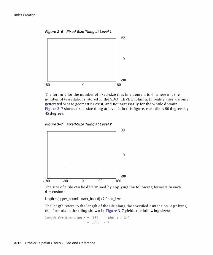
Index Creation
Figure 3–6 Fixed-Size Tiling at Level 1
The formula for the number of fixed-size tiles in a domain is 4n where n is thenumber of tessellations, stored in the SDO_LEVEL column. In reality, tiles are onlygenerated where geometries exist, and not necessarily for the whole domain.Figure 3–7 shows fixed-size tiling at level 2. In this figure, each tile is 90 degrees by45 degrees.
Figure 3–7 Fixed-Size Tiling at Level 2
The size of a tile can be determined by applying the following formula to eachdimension:
length = (upper_bound - lower_bound) / 2 ^ sdo_level
The length refers to the length of the tile along the specified dimension. Applyingthis formula to the tiling shown in Figure 3–7 yields the following sizes:
length for dimension X = (180 - (-180) ) / 2̂ 2 = (360) / 4
-180 0 180
90
-90
0
-180 -90 0 90 180
90
-90
0
3-12 Oracle8i Spatial User’s Guide and Reference

Index Creation
= 90length for dimension Y = (90 - (-90) ) / 2̂ 2 = (180) / 4 = 45
At level 2 the tiles are 90x45 degrees in size. As the number of levels increases, thetiles become smaller and smaller. Smaller tiles provide a more precise fit of the tilesover the geometry being indexed. However, because the number of tiles generatedis unbounded, you must take into account the performance implications of usinghigher levels. The SDO_TUNE.ESTIMATE_TILING_LEVEL() function can beused to determine an appropriate level for indexing with fixed-size tiles. SeeChapter 14 for a description of this function.
Besides the performance aspects related to selecting a fixed-size tile, tessellating thegeometry into fixed-size tiles might have benefits related to the type of data beingstored, such as using tiles sized to represent 1-acre farm plots, city blocks, orindividual pixels on a display. Data modeling is an important part any databasedesign, and is essential in a spatial database where the data often represents actualphysical locations.
In Example 3–3, assume that data has been loaded into a table called ROADS, andthe SDO_GEOM_METADATA has an entry for ROADS. GEOMETRY. Use thefollowing SQL statement to create a fixed index named ROADS_FIXED on ROADS_GEOMETRY.
Example 3–3 Create a Fixed Index
CREATE INDEX ROADS_FIXED ON ROADS(GEOMETRY) INDEXTYPE IS MDSYS.SPATIAL_INDEX PARAMETERS(’SDO_LEVEL = 8’);
The value in SDO_LEVEL is used while tessellating objects. Increasing the levelresults in smaller tiles and better geometry approximations. See the description ofthe ESTIMATE_TILING_LEVEL() function in Chapter 14 for information onestimating the tiling level in several different ways.
3.2.3 Hybrid Spatial Indexing with Fixed-Size and Variable-Sized TilesThis section describes hybrid indexing, which uses both fixed-size andvariable-sized tiles as a spatial indexing mechanism. For each geometry, you willhave a set of fixed-size tiles that fully cover the geometry, and a set ofvariable-sized tiles that fully cover the geometry.The terms hybrid indexing, hybridtiling, and hybrid tessellation are used interchangeably in this section.
Loading and Indexing Spatial Object Types 3-13

Index Creation
To use hybrid tiling, the SDO_LEVEL and SDO_NUMTILES keywords in thePARAMETERS clause must contain valid values. Both SDO_LEVEL and SDO_NUMTILES must be greater than 1.
The SDO_NUMTILES value determines the number of variable tiles that will beused to fully cover a geometry being indexed. Typically this value is small. Forpoints, SDO_NUMTILES is always one. For other element types, you might setSDO_NUMTILES to a value around 8. The larger the SDO_NUMTILES parameter,the better the tiles will approximate the geometry being covered. This improves theselectivity of the primary filter, but also increases the number of index entries pergeometry (see Section 4.2.1 and Section 4.2.2 for a discussion of primary andsecondary filters). The SDO_NUMTILES value should be larger for long, linearspatial entities, such as major highways or rivers, than it would be for area-relatedspatial entities such as county or state boundaries.
The SDO_LEVEL value determines the size of the fixed tiles used to fully cover thegeometry being indexed. Setting the proper SDO_LEVEL value may appear morelike art than science. Performing some simple data analysis and testing puts theprocess back in the realm of science. One approach would be use the SDO_TUNE.ESTIMATE_TILING_LEVEL() function to determine an appropriatestarting SDO_LEVEL value, and then compare the performance with slightlyhigher or lower values. This, and other techniques, are described in Appendix A,"Tuning Tips and Sample SQL Scripts".
As in Example 3–3, assume that the ROADS table has been loaded. Use thefollowing statement to create the spatial index on ROADS.GEOMETRY:
CREATE INDEX ROADS_FIXED ON ROADS(GEOMETRY) INDEXTYPE IS MDSYS.SPATIAL_INDEX PARAMETERS(’SDO_LEVEL = 6, SDO_NUMTILES=12’);
3-14 Oracle8i Spatial User’s Guide and Reference

Querying Spati
4
Querying Spatial DataThis chapter describes how the structures of an object-relational model Spatiallayer are used to resolve spatial queries and spatial joins. For the sake of clarity, theexamples all use fixed-size tiling, but hybrid indexing is actually recommended forthe object model.
4.1 Query ModelSpatial uses a two-tier query model to resolve spatial queries and spatial joins. Theterm is used to indicate that two distinct operations are performed in order toresolve queries. If both operations are performed, the exact result set is returned.
The two operations are referred to as primary and secondary filter operations.
■ The primary filter permits fast selection of candidate records to pass along tothe secondary filter. The primary filter uses geometry approximations (or indextiles) to reduce computational complexity and is considered a lower cost filter.
■ The secondary filter applies exact computational geometry to the result set ofthe primary filter. These exact computations yield the exact answer to a query.The secondary filter operations are computationally more expensive, but theyare applied only to the relatively small result set returned from the primaryfilter.
4.2 Spatial Query An important concept in the spatial data model is that each geometry isrepresented by a set of exclusive and exhaustive tiles. This means that no tilesoverlap each other (exclusive), and the tiles fully cover the object (exhaustive).
al Data 4-1

Spatial Query
Consider the following layer containing several objects in Figure 4–1. Each object islabeled with its SDO_GID. The relevant tiles are labeled with ‘Tn’.
Figure 4–1 Tessellated Layer with Multiple Objects
1243
1013
T1 T2 T7
T3 T4
T6T5
61
T8 T9
501
12
4-2 Oracle8i Spatial User’s Guide and Reference

Spatial Query
A typical spatial query is to request all objects that lie within a defined fence orwindow. A query window is shown in Figure 4–2 by the dotted-line box. Adynamic query window refers to a fence that is not defined in the database, butthat must be defined prior to using it.
Figure 4–2 Tessellated Layer with a Query Window
1243
12
1013
T1 T2 T7
T3 T4
T6T5
61
T8 T9
501
Querying Spatial Data 4-3

Spatial Query
4.2.1 Primary FilterSpatial release 8.1 provides a new operator named SDO_FILTER( ). Thisimplements the primary filter portion of the two-step process involved in theproduct’s query processing model. The primary filter uses the index data only todetermine a set of candidate object pairs that may interact. The syntax is as follows:
SDO_FILTER(geometry1 MDSYS.SDO_GEOMETRY, geometry2 MDSYS.SDO_GEOMETRY, params VARCHAR2)
Where:
■ geometry1 is a column of type MDSYS.SDO_GEOMETRY in a table.Geometry1 must be spatially indexed.
■ geometry2 is an object of type MDSYS.SDO_GEOMETRY. Geometry2may or may not come from a table. If it comes from a table, it may or maynot be spatially indexed.
■ params is a a quoted string of keyword value pairs that determine thebehavior of the operator. See the SDO_FILTER operator in Chapter 9 for alist of parameters.
The following examples perform a primary filter operation only. They will returnall the geometries shown in Figure 4–2 that have an index tile in common with oneof the index tiles that approximates the query window: tiles T1, T2, T2, and T4. Theresult of the following examples are geometries with IDs 1013, 1243, 12, and 501.
As mentioned previously, these examples are performed with fixed-size tiles,which is not the recommended indexing method for the object model. If hybridindexing was used, the selectivity would improve.
Example 4–1 performs a primary filter operation without inserting the querywindow into a table. The window will be indexed in memory and performance willbe very good.
Example 4–1 Primary Filter with a Temporary Query Window
SELECT A.Feature_ID FROM TARGET A WHERE mdsys.sdo_filter(A.shape, mdsys.sdo_geometry(3,NULL,NULL, mdsys.sdo_elem_info(1,3,3), mdsys.sdo_ordinates(x1,y1, x2,y2)), ’querytype=window’) = ’TRUE’;
Note that (x1,y1) and (x2,y2) are the lower left and upper right corners of the querywindow.
4-4 Oracle8i Spatial User’s Guide and Reference

Spatial Query
In Example 4–2, a transient instance of type SDO_GEOMETRY was constructed forthe query window instead of specifying the window parameters in the query itself.
Example 4–2 Primary Filter with a Transient Instance of the Query Window
SELECT A.Feature_ID FROM TARGET A WHERE mdsys.sdo_filter(A.shape, :theWindow,’querytype=window’) = ‘TRUE’;
Example 4–31 assumes the query window was inserted into a table calledWINDOWS, with an ID of ’WINS_1’.
Example 4–3 Primary Filter with a Stored Query Window
SELECT A.Feature_ID FROM TARGET A, WINDOWS B WHERE B.ID= ’WIN_1’ AND mdsys.sdo_filter(A.shape, B.shape,’querytype=window’) = ‘TRUE’;
If the B.shape column is not spatially indexed, the SDO_FILTER( ) operator indexesthe query window in memory and performance is very good.
If the B.shape column is spatially indexed with the same SDO_LEVEL value as theA.shape column, the SDO_FILTER( ) operator reuses the existing index, andperformance is very good or better.
If the B.shape column is spatial indexed with a different SDO_LEVEL value thanthe A.shape column, the SDO_FILTER( ) operator reuses the existing index, butperformance degrades.
4.2.2 Primary and Secondary FilterThe SDO_RELATE( ) operator performs both the primary and secondary filterstages when processing a query. The syntax of the operator is as follows:
SDO_RELATE(geometry1 MDSYS.SDO_GEOMETRY, geometry2 MDSYS.SDO_GEOMETRY, params VARCHAR2)
Where:
1 A limitation in SQLPLUS may result in an error if Example 4–3 is run in SQLPLUS. Thiserror results when both tables are indexed, and it can occur with any Spatial operator(primary or secondary filter). The error does not occur with any other interface thanSQLPLUS. The limitation will be fixed in a future release.
Querying Spatial Data 4-5
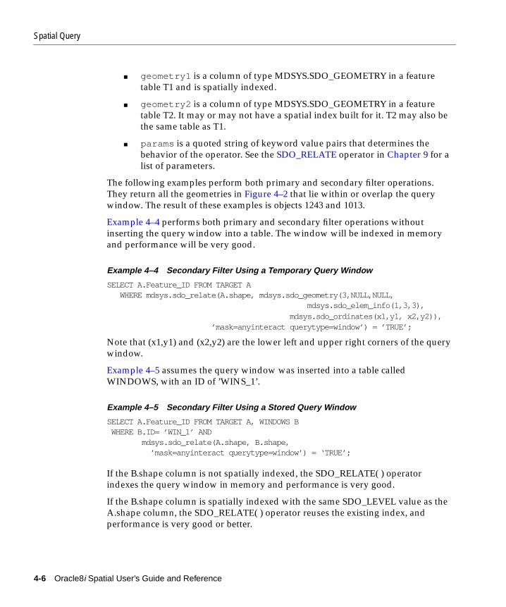
Spatial Query
■ geometry1 is a column of type MDSYS.SDO_GEOMETRY in a featuretable T1 and is spatially indexed.
■ geometry2 is a column of type MDSYS.SDO_GEOMETRY in a featuretable T2. It may or may not have a spatial index built for it. T2 may also bethe same table as T1.
■ params is a quoted string of keyword value pairs that determines thebehavior of the operator. See the SDO_RELATE operator in Chapter 9 for alist of parameters.
The following examples perform both primary and secondary filter operations.They return all the geometries in Figure 4–2 that lie within or overlap the querywindow. The result of these examples is objects 1243 and 1013.
Example 4–4 performs both primary and secondary filter operations withoutinserting the query window into a table. The window will be indexed in memoryand performance will be very good.
Example 4–4 Secondary Filter Using a Temporary Query Window
SELECT A.Feature_ID FROM TARGET A WHERE mdsys.sdo_relate(A.shape, mdsys.sdo_geometry(3,NULL,NULL, mdsys.sdo_elem_info(1,3,3), mdsys.sdo_ordinates(x1,y1, x2,y2)), ’mask=anyinteract querytype=window’) = ’TRUE’;
Note that (x1,y1) and (x2,y2) are the lower left and upper right corners of the querywindow.
Example 4–5 assumes the query window was inserted into a table calledWINDOWS, with an ID of ’WINS_1’.
Example 4–5 Secondary Filter Using a Stored Query Window
SELECT A.Feature_ID FROM TARGET A, WINDOWS B WHERE B.ID= ’WIN_1’ AND mdsys.sdo_relate(A.shape, B.shape, ’mask=anyinteract querytype=window’) = ‘TRUE’;
If the B.shape column is not spatially indexed, the SDO_RELATE( ) operatorindexes the query window in memory and performance is very good.
If the B.shape column is spatially indexed with the same SDO_LEVEL value as theA.shape column, the SDO_RELATE( ) operator reuses the existing index, andperformance is very good or better.
4-6 Oracle8i Spatial User’s Guide and Reference

Spatial Query
If the B.shape column is spatial indexed with a different SDO_LEVEL value thanthe A.shape column, the SDO_RELATE( ) operator reuses the existing index, butperformance degrades.
4.2.3 Within Distance OperatorThe SDO_WITHIN_DISTANCE( ) operator is used to determine the set of objects ina table that are within N Euclidean distance units from a reference objectaRefGeom. The reference object may be a transient or persistent instance ofMDSYS.SDO_GEOMETRY (such as a temporary query fence or a permanentgeometry stored in the database.) The syntax is as follows:
SDO_WITHIN_DISTANCE(geometry1 MDSYS.SDO_GEOMETRY, aRefGeom MDSYS.SDO_GEOMETRY, params VARCHAR2)
Where:
■ T1.Col is a column of type MDSYS.SDO_GEOMETRY in a table.Geometry1 must be spatially indexed.
■ aRefGeom is an instance of type MDSYS.SDO_GEOMETRY
■ params is a a quoted string of keyword value pairs that determines thebehavior of the operator. See the SDO_WITHIN_DISTANCE operator inChapter 9 for a list of parameters.
The following example selects any objects within 1.35 distance units from the querywindow:
SELECT A.Feature_IDFROM TARGET AWHERE MDSYS.SDO_WITHIN_DISTANCE( A.shape, :theWindow, ’distance=1.35’) = ’TRUE’;
The distance units are based on the geometry coordinate system in use. If your dataconsists of latitude and longitude pairs, then one distance unit corresponds to thelength of one degree. For city, county, state, and even country-wide applications,this is probably acceptable. Unfortunately, one degree of longitude at the equator ismuch different than one degree at the poles. As mentioned previously, the Spatialproduct treats the coordinate space as a flat Cartesian grid. It currently does nottake projections into account. Projections are left up to the application.
This operator is not suitable for performing spatial joins. That is, a query like ‘Findall parks that are within 10 distance units from coastlines’ will not be processed asan index-based spatial join of the COASTLINES and PARKS tables. Instead, it will
Querying Spatial Data 4-7
Spatial Join
be processed as a nested loop query in which each COASTLINE instance is in turna reference object that is buffered, indexed, and evaluated against the PARKS table.Thus the SDO_WITHIN_DISTANCE( ) operation is performed N times if there areN rows in the COASTLINES table.
There is an efficient way to accomplish a spatial join that involves buffering all thegeometries of a layer. This method does not use the SDO_WITHIN_DISTANCE( )operator. First, create a new table COSINE_BUFS as follows:
CREATE TABLE cosine_bufs UNRECOVERABLE AS SELECT SDO_BUFFER (A.SHAPE, B.DIMINFO, 1.35) FROM COSINE A, SDO_GEOM_METADATA B WHERE TABLE_NAME=’COSINES’ AND COLUMN_NAME=’SHAPE’;
Next, create a spatial index on the SHAPE column of COSINE_BUFS. Then you canperform the following query:
SELECT a.gif, b.gid FROM parks A cosine_bufs B WHERE SDO_Relate(A.shape, B.shape, ’mask=ANYINTERACT querytype=JOIN’) =’TRUE’;
4.3 Spatial JoinA spatial join is the same as a regular join except that the predicate involves aspatial operator. In Spatial, a spatial join takes place when you compare all thegeometries of one layer to all the geometries of another layer. This is unlike a querywindow that only compares a single geometry to all geometries of a layer.
Spatial joins can be used to answer questions such as, “which highways crossnational parks?”
The following table structures illustrate how the join would be accomplished forthis example:
PARKS( GID VARCHAR2(32), SHAPE MDSYS.SDO_GEOMETRY)HIGHWAYS( GID VARCHAR2(32), SHAPE MDSYS.SDO_GEOMETRY)
The primary filter would identify pairs of PARK GIDs and HIGHWAY GIDs thatinteract in their index entries. The query that performs the PRIMARY filter join is:
SELECT A.GID, B.GID FROM PARKS A, HIGHWAYS B WHERE mdsys.sdo_filter(A.shape, B.shape, ’querytype = join’) = ’TRUE’;
4-8 Oracle8i Spatial User’s Guide and Reference

Spatial Join
The original question, asking about highways that cross national parks, requiresthe secondary filter operator because we need to find the exact relation betweenhighways and parks.
The query that performs this join using both PRIMARY and SECONDARY filters is:
SELECT A.GID, B.GID FROM parks A, highwaysB WHERE mdsys.sdo_relate(A.shape, B.shape, ’mask = ANYINTERACT querytype = join’);
Querying Spatial Data 4-9

Spatial Join
4-10 Oracle8i Spatial User’s Guide and Reference

Indexing Statements for Object Relationa
5
Indexing Statements for Object RelationalModel
This chapter describes the statements used when working with the spatial objectdata type. The statements are listed in Table 5–1.
Table 5–1 Spatial Index Creation and Usage Statements
Statement Description
ALTER INDEX Alter a spatial index on a column of typeMDSYS.SDO_GEOMETRY.
ALTER INDEX REBUILD Rebuild a spatial index on a column of typeMDSYS.SDO_GEOMETRY.
ALTER INDEX RENAME TO Change the name of a spatial index on a columnof type MDSYS.SDO_GEOMETRY.
CREATE INDEX Create a spatial index on a column of typeMDSYS.SDO_GEOMETRY.
DROP INDEX Delete a spatial index on a column of typeMDSYS.SDO_GEOMETRY
l Model 5-1

ALTER INDEX
ALTER INDEX
PurposeThis statement alters specific parameters for a spatial index or rebuilds a spatialindex.
SyntaxALTER INDEX [schema.]index PARAMETERS (‘index_params [physical_storage_params]’ )
Keywords and Parameters
INDEX_PARAMS Allows you to change the type, (fixed or hybrid), and characteristicsof the spatial index.
Keyword Description
add_index Specifies the name of the new index table to add.Data type is VARCHAR2.
delete_index Specifies the name of the index table to delete. You can only deleteindex tables that were created with the ALTER INDEX add_indexstatement. The primary index table cannot be deleted with thisparameter. To delete the primary index table, use DROP INDEX.Data type is VARCHAR2.
sdo_level Specifies the desired fixed-size tiling level.Data type is NUMBER.
sdo_numtiles Specifies the number of variable-sized tiles to be used in tessellatingan object.Data type is NUMBER.
sdo_maxlevel Specifies the maximum tiling level. This parameter determines thetiling resolution. It must be greater than the sdo_level minimum tilinglevel. Modifying the default value is not recommended.Data type is NUMBER.Default is 32.
sdo_commit_interval
Specifies the number of underlying table rows that are processedbetween commit intervals for the index data. The default behaviorcommits the index data only after all rows in the underlying tablehave been processed. See the Usage Notes for further details.Data type is NUMBER.
5-2 Oracle8i Spatial User’s Guide and Reference

ALTER INDEX
Prerequisites■ You must have EXECUTE privileges on the index type and its implementation
type.
■ The spatial index to be altered is not marked in-progress.
Usage NotesThis statement is used to change the parameters of an existing index. This is theonly way you can add or build multiple indexes on the same column.
PHYSICAL_STORAGE_PARAMS
Determines the storage parameters used for altering the spatial indexdata table. A spatial index data table is a standard Oracle table with aprescribed format. Not all physical_storage_params that are allowedin the STORAGE clause of a CREATE TABLE statement aresupported. The following is a list of the supported subset.
Keyword Description
tablespace Specifies the tablespace in which the index data table is created. Thisparameter is the same as TABLESPACE in the STORAGE clause of aCREATE TABLE statement.
initial Is the same as INITIAL in the STORAGE clause of a CREATE TABLEstatement.
next Is the same as NEXT in the STORAGE clause of a CREATE TABLEstatement.
minextents Is the same as MINEXTENTS in the STORAGE clause of a CREATETABLE statement.
maxextents Is the same as MAXEXTENTS in the STORAGE clause of a CREATETABLE statement.
pctincrease Is the same as PCTINCREASE in the STORAGE clause of a CREATETABLE statement.
btree_initial Is the same as INITIAL in the STORAGE clause of a CREATE INDEXstatement in the case of a standard btree index.
btree_next Is the same as NEXT in the STORAGE clause of a CREATE INDEXstatement in the case of a standard btree index.
btree_pctincrease Is the same as PCTINCREASE in the STORAGE clause of a CREATEINDEX statement in the case of a standard btree index.
Indexing Statements for Object Relational Model 5-3

ALTER INDEX
ExamplesALTER INDEX qtree PARAMETERS (’add_index=HYBRID_INDEX sdo_numtiles=8 initial=100M next=1M pctincrease=0 btree_initial=5M btree_next=1M btree_pctincrease=0’);
Related Topics■ ALTER INDEX REBUILD
■ ALTER INDEX RENAME TO
5-4 Oracle8i Spatial User’s Guide and Reference

ALTER INDEX REBUILD
ALTER INDEX REBUILD
PurposeThis function rebuilds a spatial index.
SyntaxALTER INDEX [schema.]index REBUILD [PARAMETERS (‘rebuild_params [physical_storage_params]’ ) ]
Keywords and Parameters
REBUILD_PARAMS
Specifies in a command string the index parameters to use inrebuilding the spatial index.
Keyword Description
rebuild_index Specifies the name of the spatial index table to be rebuilt.Data type is VARCHAR2.
sdo_level Specifies the desired fixed-size tiling level.Data type is NUMBER.
sdo_numtiles Specifies the number of variable-sized tiles to be used in tessellatingan object.Data type is NUMBER.
sdo_maxlevel Specifies the maximum tiling level. This parameter determines thetiling resolution. It must be greater than the sdo_level minimum tilinglevel. Modifying the default value is not recommended.Data type is NUMBER.Default is 32.
sdo_commit_interval
Specifies the number of underlying table rows that are processedbetween commit intervals for the index data. The default behavior isthat a commit of the index data is done only after all rows in theunderlying table have been processed. See the Usage Notes forfurther details.Data type is NUMBER.
layer_gtype Specifies special processing for point data.
If the layer you are indexing is all points, set the parameter to’POINT’ for optimal performance.Data type is VARCHAR2.
Indexing Statements for Object Relational Model 5-5

ALTER INDEX REBUILD
Prerequisites■ You must have EXECUTE privileges on the index type and its implementation
type.
■ The spatial index to be altered is not marked in-progress.
Usage Notes■ sdo_commit_interval: An ALTER INDEX REBUILD ‘rebuild_params’
statement will rebuild the index using supplied parameters. Spatial indexcreation involves creating and inserting index data, for each row in theunderlying table column being spatially indexed, into a table with a prescribedformat. The default, or normal, operation is that all rows in the underlyingtable are processed before the insertion of index data is committed. Thisrequires adequate rollback segment space.
PHYSICAL_STORAGE_PARAMS
Determines the storage parameters used for rebuiding the spatialindex data table. A spatial index data table is a regular Oracle tablewith a prescribed format. Not all physical_storage_params that areallowed in the STORAGE clause of a CREATE TABLE statement aresupported. The following is a list of the supported subset.
Keyword Description
tablespace Specifies the tablespace in which the index data table is created. Sameas ‘TABLESPACE’ in the STORAGE clause of a CREATE TABLEstatement.
initial Is the same as INITIAL in the STORAGE clause of a CREATE TABLEstatement.
next Is the same as NEXT in the STORAGE clause of a CREATE TABLEstatement.
minextents Is the same as MINEXTENTS in the STORAGE clause of a CREATETABLE statement.
maxextents Is the same as MAXEXTENTS in the STORAGE clause of a CREATETABLE statement.
pctincrease Is the same as PCTINCREASE in the STORAGE clause of a CREATETABLE statement.
btree_initial Is the same as INITIAL in the STORAGE clause of a CREATE INDEXstatement in the case of a standard B-tree index.
btree_next Is the same as NEXT in the STORAGE clause of a CREATE INDEXstatement in the case of a standard B-tree index.
btree_pctincrease Is the same as PCTINCREASE in the STORAGE clause of a CREATEINDEX statement in the case of a standard B-tree index.
5-6 Oracle8i Spatial User’s Guide and Reference

ALTER INDEX REBUILD
■ You may choose to perform commits of index data after every N rows of theunderlying table have been processed. This is done by specifying that sdo_commit_interval = N. The potential complication is that if there is an errorduring index rebuild and periodic commits have taken place, then the spatialindex will be in an inconsistent state. The only recovery option is to use DROPINDEX (possibly with the FORCE option) and CREATE INDEX statementsafter ensuring that the various tablespaces are the required size and any othererror conditions have been removed.
■ This command does not remember any previous index parameters. Allparameters should be specified for the index you want to rebuild.
ExamplesThe following example builds oldindex with an SDO_LEVEL = 12 and SDO_NUMTILES = NULL.
ALTER INDEX oldindex REBUILD PARAMETERS(’sdo_level = 12’);
Related Topics■ CREATE INDEX
■ DROP INDEX
Indexing Statements for Object Relational Model 5-7

ALTER INDEX RENAME TO
ALTER INDEX RENAME TO
PurposeThis statement alters the name of a spatial index.
SyntaxALTER INDEX [schema.]index RENAME TO <new_index_name>
Keywords and Parameters
Prerequisites■ You must have EXECUTE privileges on the index type and its implementation
type.
■ The spatial index to be altered is not marked in-progress.
Usage NotesNone.
ExamplesThe following example renames the index ‘oldindex’ to ‘newindex’.
ALTER INDEX oldindex RENAME TO newindex ;
Related Topics■ CREATE INDEX
■ DROP INDEX
new_index_name Specifies the new name of the index.
5-8 Oracle8i Spatial User’s Guide and Reference

CREATE INDEX
CREATE INDEX
PurposeThis statement creates a spatial index on a column of type MDSYS.SDO_GEOMETRY.
SyntaxCREATE INDEX [schema.]<index_name> ON [schema.]<tableName> (column)
INDEXTYPE IS MDSYS.SPATIAL_INDEX
[PARAMETERS ‘index_params [physical_storage_params]’);
Keywords and Parameters
INDEX_PARAMS Determine the type, fixed or hybrid, and characteristics of the spatialindex.
Keyword Description
sdo_level Specifies the desired fixed-size tiling level.Data type is NUMBER.
sdo_numtiles Specifies the number of variable-sized tiles to be used in tessellatingan objectData type is NUMBER.
sdo_maxlevel Specifies the maximum tiling level. This parameter determines thetiling resolution. It must be set greater than the sdo_level minimumtiling level. Modifying the default value is not recommended.Data type is NUMBER.Default is 32.
sdo_commit_interval
Specifies the number of underlying table rows that are processedbetween commit intervals for the index data. The default behavior isthat a commit of the index data is done only after all rows in theunderlying table have been processed. See the Usage Notes forfurther details.Data type is NUMBER.
layer_gtype Specifies special processing for point data.
If the layer you are indexing is all points, set this parameter to’POINT’ for optimal performance.Data type is VARCHAR2.
Indexing Statements for Object Relational Model 5-9
CREATE INDEX
Prerequisites■ All the current SQL CREATE INDEX prerequisites apply.
■ You must have EXECUTE privilege on the index type and its implementationtype.
■ The SDO_GEOM_METADATA table must contain an entry with thedimensions and coordinate boundary information for the table column to bespatially indexed.
Usage Notes■ Other options available for regular indexes (such as ASC and DESC) are not
applicable for spatial indexes.
PHYSICAL_STORAGE_PARAMS
Determines the storage parameters used for creating the spatial indexdata table. A spatial index data table is a regular Oracle table with aprescribed format. Not all physical_storage_params that are allowedin the STORAGE clause of a CREATE TABLE statement aresupported. The following is a list of the supported subset.
Keyword Description
tablespace Specifies the tablespace in which the index data table is created. Sameas ‘TABLESPACE’ in the STORAGE clause of a CREATE TABLEstatement.
initial Is the same as INITIAL in the STORAGE clause of a CREATE TABLEstatement.
next Is the same as NEXT in the STORAGE clause of a CREATE TABLEstatement.
minextents Is the same as MINEXTENTS in the STORAGE clause of a CREATETABLE statement.
maxextents Is the same as MAXEXTENTS in the STORAGE clause of a CREATETABLE statement.
pctincrease Is the same as PCTINCREASE in the STORAGE clause of a CREATETABLE statement.
btree_initial Is the same as INITIAL in the STORAGE clause of a CREATE INDEXstatement in the case of a standard B-tree index.
btree_next Is the same as NEXT in the STORAGE clause of a CREATE INDEXstatement in the case of a standard B-tree index.
btree_pctincrease Is the same as PCTINCREASE in the STORAGE clause of a CREATEINDEX statement in the case of a standard B-tree index.
5-10 Oracle8i Spatial User’s Guide and Reference

CREATE INDEX
■ The index_params string must contain valid values for either SDO_LEVEL orboth SDO_LEVEL and SDO_NUMTILES.
■ DEFAULT VALUES:
– sdo_numtiles must be supplied with a value greater than or equal to one toperform hybrid indexing. If this parameter is not supplied, indexing withfixed-size tiles is performed.
– sdo_commit_interval does not allow spatial data to be committed atintervals. Insertion of spatial index data is committed only at the end of theindex creation process. That is, it is committed after all rows in theunderlying table have been processed.
– sdo_maxlevel equals 32. Modification is not recommended.
■ SDO_LEVEL must be greater than zero and less than SDO_MAXLEVEL
■ The value passed to SDO_NUMTILES is considered a recommendation. Insome cases, this value may be overwritten by the indexing algorithm.
■ sdo_commit_interval: Spatial index creation involves creating and insertingindex data for each row in the underlying table column being spatially indexedinto a table with a prescribed format. The default, or normal, operation is thatall rows in the underlying table are processed before the insertion of index datais committed. This requires adequate rollback segment space.
■ You may choose to commit index data after every N rows of the underlyingtable have been processed. This is done by specifying sdo_commit_interval =N. The potential complication is that if there is an error during the rebuildingof the index, and the spatial index data was periodically committed, then thespatial index will be in an inconsistent state. The only recovery option is to useDROP INDEX and CREATE INDEX statements after ensuring that the varioustablespaces are the required size, and any other error conditions have beenremoved.
■ Interpretation of SDO_LEVEL and SDO_NUMTILES value combinations areshown in Table 5–2.
Table 5–2 SDO_LEVEL and SDO_NUMTILE Combinations
SDO_LEVEL SDO_NUMTILES Type of Spatial Index
Not specified. Not specified. Error.
>= 1 Not specified. Fixed indexing, (indexing with fixed-sizetiles).
Indexing Statements for Object Relational Model 5-11

CREATE INDEX
■ If a TABLESPACE name is provided in the parameters clause, the user(underlying table owner) must have appropriate privileges for that tablespace.
■ If the CREATE INDEX statement fails because of an invalid geometry, theROWID of the failed geometry is returned in an error message along with thereason for the failure.
■ If the CREATE INDEX statement fails for any reason, then the DROP INDEXstatement must be used to clean up the partially built index and associatedmetadata. If DROP INDEX does not work, add the FORCE parameter and tryagain.
Related Topics■ ALTER INDEX
■ DROP INDEX
>= 1 >= 1 Hybrid indexing with fixed-size andvariable-sized tiles. The SDO_LEVELcolumn defines the fixed tile size. TheSDO_NUMTILES column defines thenumber of variable tiles to generate pergeometry.
Not specified. >= 1 Not supported.
Table 5–2 SDO_LEVEL and SDO_NUMTILE Combinations (Cont.)
SDO_LEVEL SDO_NUMTILES Type of Spatial Index
5-12 Oracle8i Spatial User’s Guide and Reference

DROP INDEX
DROP INDEX
PurposeThis statement deletes a spatial index.
SyntaxDROP INDEX [schema.]index [FORCE]
Keywords and Parameters
PrerequisitesYou must have EXECUTE privileges on the index type and its implementation type.
Usage NotesUse DROP INDEX indexname FORCE to clean up after a failure in the CREATEINDEX statement.
Examples1. DROP INDEX oldindex
2. DROP INDEX oldindex FORCE
Related Topics■ CREATE INDEX
FORCE Causes the spatial index to be deleted fromthe system tables even if the index is markedin-progress or some other error conditionoccurs.
Indexing Statements for Object Relational Model 5-13

DROP INDEX
5-14 Oracle8i Spatial User’s Guide and Reference

Tuning Functions and Procedures for Object-Relationa
6
Tuning Functions and Procedures forObject-Relational Model
This chapter contains descriptions of the tuning functions and procedures shown inTable 6–1.
Table 6–1 Tuning Functions and Procedures
Function/Procedure Description
SDO_TUNE.AVERAGE_MBR Calculates the average minimum bounding rectanglefor geometries in a layer.
SDO_TUNE.ESTIMATE_INDEX_PERFORMANCE
Estimates the spatial index selectivity.
SDO_TUNE.ESTIMATE_TILING_LEVEL
Determines an appropriate tiling level for creatingfixed-size index tiles.
SDO_TUNE.ESTIMATE_TILING_TIME
Estimates the tiling time for a layer, in seconds.
SDO_TUNE.EXTENT_OF Determines the minimum bounding rectangle of thedata in a layer.
SDO_TUNE.HISTOGRAM_ANALYSIS
Calculates statistical histograms for a spatial layer.
SDO_TUNE.MIX_INFO Calculates geometry type information for a spatiallayer, such as the percentage of each geometry type.
l Model 6-1

SDO_TUNE.AVERAGE_MBR
SDO_TUNE.AVERAGE_MBR
PurposeThis function calculates the average minimum bounding rectangle (MBR) for allgeometries in a column of type SDO_GEOMETRY.
SyntaxSDO_TUNE.AVERAGE_MBR (table_name, column_name, width, height)
Keywords and Parameters
ReturnsThe function returns the width and height of the average MBR for all geometries ina geometry table.
Data types for height and width are NUMBER.
Usage NotesThis function calculates the average MBR by keeping track of the maximum andminimum X and Y values for all geometries in a geometry table.
table_name Specifies the name of the geometry table toexamine.Data type is VARCHAR2.
column_name Specifies the name of the geometry object columnto examine.Data type is VARCHAR2.
width Returns the width of the average MBR.Data type is OUT NUMBER.
height Returns the height of the average MBR.Data type is OUT NUMBER.
6-2 Oracle8i Spatial User’s Guide and Reference

SDO_TUNE.ESTIMATE_INDEX_PERFORMANCE
SDO_TUNE.ESTIMATE_INDEX_PERFORMANCE
PurposeThis function estimates the spatial index performance such as query selectivity andwindow query time for a column of type SDO_GEOMETRY.
SyntaxSDO_TUNE.ESTIMATE_INDEX_PERFORMANCE (table_name, column_name, sample_ratio, tiling_level, num_tiles, window_object, tiling_time, filter_time, query_time)
Keywords and Parameters
table_name Specifies the name of the geometry table to examine.Data type is VARCHAR2.
column_name Specifies the name of the geometry object column to examine.Data type is VARCHAR2.
sample_ratio Specifies the size ratio between the original layer and thesample layer to be generated.Data type is INTEGER.Default is 20.
tiling_level Specifies the spatial index level at which the layer is to betessellated.Data type is INTEGER.
num_tiles Specifies the number of tiles for variable or hybrid tessellation.Data type is INTEGER.
window_object Specifies the name of the spatial layer in which the querywindow is stored.Data type is VARCHAR2.
tiling_time Returns the estimated tiling time in seconds.Data type is OUT NUMBER.
filter_time Returns the estimated spatial index filter time in seconds.Data type is OUT NUMBER.
query_time Returns the estimated query window time in seconds.Data type is OUT NUMBER.
Tuning Functions and Procedures for Object-Relational Model 6-3
SDO_TUNE.ESTIMATE_INDEX_PERFORMANCE
ReturnsThe function returns a number between 0.0 and 1.0 representing estimated spatialindex selectivity. Data type is NUMBER.
The function also returns the estimated tiling time, filter time, and query time. Datatype for these variables is NUMBER.
Usage Notes■ A larger selectivity number indicates better selectivity. A selectivity of 0.0
indicates an error.
■ A larger sample_ratio means faster but less accurate estimation.
6-4 Oracle8i Spatial User’s Guide and Reference

SDO_TUNE.ESTIMATE_TILING_LEVEL
SDO_TUNE.ESTIMATE_TILING_LEVEL
PurposeThis function estimates the appropriate sdo_level to use when indexing withhybrid or fixed-size tiles.
SyntaxMDSYS.SDO_TUNE.ESTIMATE_TILING_LEVEL (table_name, column_name, maxtiles, type_of_estimate)
Keywords and Parameters
ReturnsThe function returns an integer representing the level to use when creating a spatialindex for the specified layer. The function returns NULL if the data is inconsistent.
Usage NotesNone.
table_name Specifies the name of the geometry table.Data type is VARCHAR2.
column_name Specifies the name of the geometry column to examine.Data type is VARCHAR2.
maxtiles Specifies the maximum number of tiles that can be used to index therectangle defined by the type_of_estimate parameter.Data type is INTEGER.
type_of_estimate Indicates by keyword one of three different models. Specify the type ofestimate with one of the following keywords:
• LAYER_EXTENT -- Use the rectangle defined by your coordinatesystem.
• ALL_GID_EXTENT -- Use the minimum bounding rectangle thatencompasses all the geometric objects in the column. This estimate isrecommended for most applications with a maxtiles of 10,000.
• AVG_GID_EXTENT -- Use a rectangle representing the average sizeof the individual geometric objects within the column. This optionperforms the most analysis of the three types.
Data type is VARCHAR2.
Tuning Functions and Procedures for Object-Relational Model 6-5

SDO_TUNE.ESTIMATE_TILING_LEVEL
Related Topics■ MDSYS.SDO_TUNE.EXTENT_OF
■ Section A.2.2, "Understanding the Tiling Level"
■ Section A.2.4, "Visualizing the Spatial Index (Drawing Tiles)"
6-6 Oracle8i Spatial User’s Guide and Reference

SDO_TUNE.ESTIMATE_TILING_TIME
SDO_TUNE.ESTIMATE_TILING_TIME
PurposeThis function provides the estimated time to tessellate a column of typeSDO_GEOMETRY.
SyntaxSDO_TUNE.ESTIMATE_TILING_TIME (table_name, column_name, sample_ratio, tiling_level, num_tiles)
Keywords and Parameters
ReturnsThis function returns the estimated tiling time in seconds. A return of 0 indicates anerror.
Data type is NUMBER.
Usage NotesNone.
table_name Specifies the name of the geometry table to examine.Data type is VARCHAR2.
column_name Specifies the name of the geometry object column to examine.Data type is VARCHAR2.
sample_ratio Specifies the size ratio between the original layer and the sample layer tobe generated.Data type is INTEGER.Default is 20.
tiling_level Specifies the spatial index level at which the layer is to be tessellated.Data type is INTEGER.
num_tiles Specifies the number of tiles for variable or hybrid tessellation.Data type is INTEGER.
Tuning Functions and Procedures for Object-Relational Model 6-7

SDO_TUNE.EXTENT_OF
SDO_TUNE.EXTENT_OF
PurposeThis function determines the extent of all geometries in a column of typeSDO_GEOMETRY.
SyntaxSDO_TUNE.EXTENT_OF (table_name, column_name)
Keywords and Parameters
ReturnsThis function returns a geometry object representing the minimum boundingrectangle for all geometric data in a column. The function returns NULL if the datais inconsistent.
Usage NotesNone.
Related TopicsSDO_TUNE.ESTIMATE_TILING_LEVEL() function
table_name Specifies the name of the geometry table.Data type is VARCHAR2.
column_name Specifies the name of the geometry column to examine.Data type is VARCHAR2.
6-8 Oracle8i Spatial User’s Guide and Reference

SDO_TUNE.HISTOGRAM_ANALYSIS
SDO_TUNE.HISTOGRAM_ANALYSIS
PurposeThis procedure generates statistical histograms based on columns of typeSDO_GEOMETRY.
SyntaxSDO_TUNE.HISTOGRAM_ANALYSIS (table_name, column_name, result_table, type_of_histogram, max_value, intervals)
Keywords and Parameters
ReturnsThe procedure populates the result table with statistical histograms for a geometrytable.
Usage Notes■ Prior to calling this procedure, create the result table as follows:
CREATE TABLE histogram (value NUMBER, count NUMBER);
table_name Specifies the name of the geometry table to examine.Data type is VARCHAR2.
column_name Specifies the name of the geometry column to examine.Data type is VARCHAR2.
result_table Specifies the name of the result table where the histogram will be stored.Data type is VARCHAR2.
type_of_histogram Specifies one of three types of histograms:
• TILES_VS_LEVEL (default)
• GEOMS_VS_AREA
• GEOMS_VS_VERTICES
Data type is VARCHAR2.
max_value Specifies the upper limit of the histogram.Data type is NUMBER.
intervals Specifies the number of intervals between 0 and max_value.Data type is INTEGER.
Tuning Functions and Procedures for Object-Relational Model 6-9

SDO_TUNE.HISTOGRAM_ANALYSIS
■ The following types of histograms are available:
TILES_VS_LEVEL Provides the number of tiles at different spatial indexlevels. This histogram is used to evaluate the spatialindex that is already built on the data set layer.
GEOMS_VS_AREA Provides the number of geometries in different sizeranges. The shape of this histogram could be helpful inchoosing a proper index type and index level.
GEOMS_VS_VERTICES Provides a histogram of the geometry count against thenumber of vertices. This histogram could helpdetermine if spatial index selectivity is important for thelayer. Because the number of vertices determines theperformance of the secondary filter, selectivity of theprimary filter could be crucial for layers that containmany complicated geometries.
6-10 Oracle8i Spatial User’s Guide and Reference

SDO_TUNE.MIX_INFO
SDO_TUNE.MIX_INFO
PurposeThis procedure provides the number of geometries of each type stored in a columnof type SDO_GEOMETRY.
SyntaxSDO_TUNE.MIX_INFO (table_name, column_name)
Keywords and Parameters
ReturnsThe procedure calculates geometry type information for the table. It calculates thenumber of geometries of different types, as well as the percentages of points, linestrings, polygons, and complex geometries.
Usage NotesNone.
table_name Specifies the name of the geometry table to examine.Data type is VARCHAR2.
column_name Specifies the name of the geometry column to examine.Data type is VARCHAR2.
Tuning Functions and Procedures for Object-Relational Model 6-11

SDO_TUNE.MIX_INFO
6-12 Oracle8i Spatial User’s Guide and Reference

Geometry Functions for Object-Relational
7
Geometry Functions for Object-RelationalModel
This chapter contains descriptions of the geometry functions shown in Table 7–1.
Table 7–1 Geometric Functions for the Object-Relational Model
Function Description
SDO_GEOM.AREA Computes the area of a two-dimensionalpolygon.
SDO_GEOM.LENGTH Computes the length or perimeter of ageometry.
SDO_GEOM.RELATE Determines how two objects interact.
SDO_GEOM.SDO_BUFFER Generates a buffer polygon around a geometry.
SDO_GEOM.SDO_POLY_DIFFERENCE Generates a polygon representing thedifference between two geometries.
SDO_GEOM.SDO_POLY_INTERSECTION Generates a polygon representing theintersection of two geometries.
SDO_GEOM.SDO_POLY_UNION Generates a polygon representing thecombination of two geometries.
SDO_GEOM.SDO_POLY_XOR Generates a polygon representing thesymmetric difference between two geometries.
SDO_GEOM.VALIDATE_GEOMETRY Determines if a geometry is valid.
SDO_GEOM.VALIDATE_LAYER Determines if all the geometries stored in acolumn are valid.
SDO_GEOM.WITHIN_DISTANCE Determines if two geometries are within aspecified Euclidean distance from one another.
Model 7-1

SDO_GEOM.AREA
SDO_GEOM.AREA
PurposeThis function computes the area of a two-dimensional polygon.
SyntaxSDO_GEOM.AREA (geometry, dim_array)
Keywords and Parameters
ReturnsThis function returns the area of a polygon.
Data type is NUMBER.
Usage NotesThis function works with any polygon, including polygons with holes.
Related TopicsNone.
geometry Specifies the geometry object to analyze.Data type is MDSYS.SDO_GEOMETRY.
dim_array Specifies the dimensional information array, usually selectedfrom the SDO_GEOM_METADATA table.Data type is MDSYS.SDO_DIM_ARRAY.
7-2 Oracle8i Spatial User’s Guide and Reference
SDO_GEOM.LENGTH
SDO_GEOM.LENGTH
PurposeThis function computes the length or perimeter of a geometry.
SyntaxSDO_GEOM.LENGTH (geometry, dim_array)
Keywords and Parameters
ReturnsThis function returns the length or perimeter of an object.
Data type is NUMBER.
Usage NotesIf the input polygon contains one or more holes, this function calculates theperimeters of the exterior boundary and all of the holes. It returns the sum of all theperimeters.
Related TopicsNone.
geometry Specifies the geometry object to analyze.Data type is MDSYS.SDO_GEOMETRY.
dim_array Specifies the dimensional information array, usually selectedfrom the SDO_GEOM_METADATA table.Data type is MDSYS.SDO_DIM_ARRAY.
Geometry Functions for Object-Relational Model 7-3

SDO_GEOM.RELATE
SDO_GEOM.RELATE
PurposeThis function examines two geometry objects to determine their spatial relationship.
SyntaxSDO_GEOM.RELATE (geometry1, dim_array1, mask, geometry2, dim_array2)
Keywords and Parameters
ReturnsThe MDSYS.SDO_GEOM.RELATE() function can return three types of answers:
1. If you pass a mask listing one or more relationships, the function returns thename of the relationship if it is true for the pair of geometries. If all of therelationships are false, the procedure returns FALSE.
2. If you pass the DETERMINE keyword in the mask, the function returns the onerelationship keyword that best matches the geometries. DETERMINE can onlybe used when SDO_GEOM.RELATE() is in the SELECT clause of the SQLstatement.
3. If you pass the ANYINTERACT keyword in the mask, the function returnsTRUE if the two geometries are not disjoint.
The data type is VARCHAR2.
Usage NotesThe following relationships can be tested:
■ ANYINTERACT - Returns TRUE if the objects are not disjoint.
geometry1,geometry2
Specifies the geometry objects to compare.Data type is MDSYS.SDO_GEOMETRY.
dim_array1,dim_array2
Specifies the dimensional information array, usually selectedfrom the SDO_GEOM_METADATA table.Data type is MDSYS.SDO_DIM_ARRAY.
mask Specifies a list of relationships to check. See the list of keywordsin the Usage Notes.
7-4 Oracle8i Spatial User’s Guide and Reference

SDO_GEOM.RELATE
■ CONTAINS - Returns CONTAINS if the second object is entirely within thefirst object and the object boundaries do not touch; otherwise, returnsFALSE.
■ COVEREDBY - Returns COVEREDBY if the first object is entirely withinthe second object and the object boundaries touch at one or more points;otherwise, returns FALSE.
■ COVERS - Returns COVERS if the second object is entirely within the firstobject and the boundaries touch in one or more places; otherwise, returnsFALSE.
■ DISJOINT - Returns DISJOINT if the objects have no common boundary orinterior points; otherwise, returns FALSE.
■ EQUAL - Returns EQUAL if the objects share every point of theirboundaries and interior, including any holes in the objects; otherwise,returns FALSE.
■ INSIDE - Returns INSIDE if the first object is entirely within the secondobject and the object boundaries do not touch; otherwise, returns FALSE.
■ OVERLAPBDYDISJOINT - Returns OVERLAPBDYDISJOINT if the objectsoverlap, but their boundaries do not interact; otherwise, returns FALSE.
■ OVERLAPBDYINTERSECT - Returns OVERLAPBDYINTERSECT if theobjects overlap, and their boundaries intersect in one or more places;otherwise, returns FALSE.
■ TOUCH - Returns TOUCH if the two objects share a common boundarypoint, but no interior points; otherwise, returns FALSE.
Mask values can be combined using a logical Boolean operator OR. For example,‘INSIDE + TOUCH’ returns either ’INSIDE’, ’TOUCH’, or ’FALSE’ depending onthe outcome of the test.
Related Topics None.
Geometry Functions for Object-Relational Model 7-5

SDO_GEOM.SDO_BUFFER
SDO_GEOM.SDO_BUFFER
PurposeThis function generates a buffer polygon around a geometry object.
SyntaxSDO_GEOM.SDO_BUFFER (geometry, dim_array, distance)
Keywords and Parameters
ReturnsThis function returns a geometry object representing the buffer polygon.
Data type is MDSYS.SDO_GEOMETRY.
Usage NotesThis function creates a rounded buffer around a point, line, or polygon. The bufferwithin a void is also rounded, and is the same distance from the inner boundary asthe outer buffer is from the outer boundary. See Figure 1–11 for an illustration.
Related Topics■ SDO_TUNE.EXTENT_OF
■ SDO_GEOM.SDO_POLY_DIFFERENCE
■ SDO_GEOM.SDO_POLY_INTERSECTION
■ SDO_GEOM.SDO_POLY_UNION
■ SDO_GEOM.SDO_POLY_XOR
geometry Specifies the geometry objects to compare.Data type is MDSYS.SDO_GEOMETRY.
dim_array Specifies the dimensional information array, usually selectedfrom the SDO_GEOM_METADATA table.Data type is MDSYS.SDO_DIM_ARRAY.
distance Specifies the Euclidean distance value.Data type is NUMBER.
7-6 Oracle8i Spatial User’s Guide and Reference

SDO_GEOM.SDO_POLY_DIFFERENCE
SDO_GEOM.SDO_POLY_DIFFERENCE
PurposeThis function computes the difference (A minus B) of two polygon objects.
SyntaxSDO_GEOM.SDO_POLY_DIFFERENCE (geometry1, dim_array1, geometry2, dim_array2)
Keywords and Parameters
ReturnsThis function returns a geometry object representing the difference of two polygonobjects.
Data type is MDSYS.SDO_GEOMETRY.
Usage NotesNone.
Related Topics■ SDO_GEOM.SDO_POLY_BUFFER
■ SDO_GEOM.SDO_POLY_INTERSECTION
■ SDO_GEOM.SDO_POLY_UNION
■ SDO_GEOM.SDO_POLY_XOR
geometry1,geometry2
Specifies the geometry objects to compare.Data type is MDSYS.SDO_GEOMETRY.
dim_array1,dim_array2
Specifies the dimensional information array, usually selectedfrom the SDO_GEOM_METADATA table.Data type is MDSYS.SDO_DIM_ARRAY.
Geometry Functions for Object-Relational Model 7-7

SDO_GEOM.SDO_POLY_INTERSECTION
SDO_GEOM.SDO_POLY_INTERSECTION
PurposeThis function computes the intersection of two polygon objects.
SyntaxSDO_GEOM.SDO_POLY_INTERSECTION (geometry1, dim_array1, geometry2, dim_array2)
Keywords and Parameters
ReturnsThis function returns a geometry object representing the intersection (A and B) oftwo polygon objects.
Data type is MDSYS.SDO_GEOMETRY.
Usage NotesNone.
Related Topics■ SDO_GEOM.SDO_POLY_BUFFER
■ SDO_GEOM.SDO_POLY_DIFFERENCE
■ SDO_GEOM.SDO_POLY_UNION
■ SDO_GEOM.SDO_POLY_XOR
geometry1,geometry2
Specifies the geometry objects to compare.Data type is MDSYS.SDO_GEOMETRY.
dim_array1,dim_array2
Specifies the dimensional information array, usually selectedfrom the SDO_GEOM_METADATA table.Data type is MDSYS.SDO_DIM_ARRAY.
7-8 Oracle8i Spatial User’s Guide and Reference
SDO_GEOM.SDO_POLY_UNION
SDO_GEOM.SDO_POLY_UNION
PurposeThis function computes the union of two polygon objects.
SyntaxSDO_GEOM.SDO_POLY_UNION (geometry1, dim_array1, geometry2, dim_array2)
Keywords and Parameters
ReturnsThis function returns a geometry object representing the union (A or B) of twopolygon objects.
Data type is MDSYS.SDO_GEOMETRY.
Usage NotesNone.
Related Topics■ SDO_GEOM.SDO_POLY_BUFFER
■ SDO_GEOM.SDO_POLY_DIFFERENCE
■ SDO_GEOM.SDO_POLY_INTERSECTION
■ SDO_GEOM.SDO_POLY_XOR
geometry1,geometry2
Specifies the geometry objects to compare.Data type is MDSYS.SDO_GEOMETRY.
dim_array1,dim_array2
Specifies the dimensional information array, usually selectedfrom the SDO_GEOM_METADATA table.Data type is MDSYS.SDO_DIM_ARRAY.
Geometry Functions for Object-Relational Model 7-9

SDO_GEOM.SDO_POLY_XOR
SDO_GEOM.SDO_POLY_XOR
PurposeThis function computes the symmetric difference of two polygon objects.
SyntaxSDO_GEOM.SDO_POLY_XOR (geometry1, dim_array1, geometry2, dim_array2)
Keywords and Parameters
ReturnsThis function returns a geometry object representing the symmetric difference (Axor B) of two polygon objects.
Data type is MDSYS.SDO_GEOMETRY.
Usage NotesNone.
Related Topics■ SDO_GEOM.SDO_POLY_BUFFER
■ SDO_GEOM.SDO_POLY_DIFFERENCE
■ SDO_GEOM.SDO_POLY_INTERSECTION
■ SDO_GEOM.SDO_POLY_UNION
geometry1,geometry2
Specifies the geometry objects to compare.Data type is MDSYS.SDO_GEOMETRY.
dim_array1,dim_array2
Specifies the dimensional information array, usually selectedfrom the SDO_GEOM_METADATA table.Data type is MDSYS.SDO_DIM_ARRAY.
7-10 Oracle8i Spatial User’s Guide and Reference
SDO_GEOM.VALIDATE_GEOMETRY
SDO_GEOM.VALIDATE_GEOMETRY
PurposeThis function provides a consistency check for valid geometry types. The functionchecks the representation of the geometry from the tables against the elementdefinitions.
SyntaxSDO_GEOM.VALIDATE_GEOMETRY (geometry, dim_array)
Keywords and Parameters
ReturnsThis function returns:
■ TRUE if the geometry is valid.
■ FALSE if the geometry fails for some unknown reason.
■ An Oracle error message number based on the specific reason the geometryin invalid.
Data type is VARCHAR2.
Usage NotesThis function checks for the following:
■ Polygons have at least four points, which includes the point that closes thepolygon. (The last point is the same as the first.)
■ Line strings have at least two points.
■ In a heterogeneous collection (SDO_GTYPE 4) or multipolygon (SDO_GTYPE7), all polygons are disjoint.
geometry Specifies the geometry object to test.Data type is MDSYS.SDO_GEOMETRY.
dim_array Specifies the dimensional information array, usually selectedfrom the SDO_GEOM_METADATA table.Data type is MDSYS.SDO_DIM_ARRAY.
Geometry Functions for Object-Relational Model 7-11
SDO_GEOM.VALIDATE_GEOMETRY
ExampleThe following example tests a geometry stored in a table my_geometry_table withone column called "geometry" and another column called "my_id," which is theprimary key:
SELECT mdsys.sdo_geom.validate_geometry (a.geometry, b.diminfo) FROM abi_81_hy a, sdo_geom_metadata b WHERE a.gid = 1 AND b.table_name = 'MY_GEOMETRY_TABLE' AND b.column_name = 'GEOMETRY';
Related TopicsNone.
7-12 Oracle8i Spatial User’s Guide and Reference

SDO_GEOM.VALIDATE_LAYER
SDO_GEOM.VALIDATE_LAYER
PurposeThis function examines a geometry column to determine if the stored geometriesfollow the defined rules for geometry objects.
SyntaxSDO_GEOM.VALIDATE_LAYER (table_name, column_name, pkey_column, result_table_name)
Keywords and Parameters
ReturnsThis function populates the result table with validation results.
Usage Notes■ An empty result table must be created prior to calling this function. The format
of the result table is: (sdo_gid number, result varchar2(10)).
■ This function returns TRUE in the result table if a geometry is valid. If it isinvalid, the result column for that geometry (the pkey_column corresponds tothe SDO_GID) contains an Oracle error message number. You can then look upthis error message to determine the cause of the failure.
■ This function checks for the following:
– Polygons have at least four points, which includes the point that closes thepolygon. (The last point is the same as the first.)
– Line strings have at least two points.
table_name Specifies the name of the geometry object table.Data type is VARCHAR2.
column_name Specifies the name of the geometry object column to examine.Data type is VARCHAR2.
pkey_column Specifies the primary key column. This can be the rowid, or anyother primary key.Data type is VARCHAR2.
result_table_name Specifies the name of the result table.Data type is VARCHAR2.
Geometry Functions for Object-Relational Model 7-13

SDO_GEOM.VALIDATE_LAYER
– In a heterogeneous collection (SDO_GTYPE 4) or multipolygon (SDO_GTYPE 7), all polygons are disjoint.
Related TopicsNone.
7-14 Oracle8i Spatial User’s Guide and Reference

SDO_GEOM.WITHIN_DISTANCE
SDO_GEOM.WITHIN_DISTANCE
PurposeThis function determines if two spatial objects are within some specified Euclideandistance from each other.
SyntaxSDO_GEOM.WITHIN_DISTANCE (geometry1, dim_array1, distance, geometry2, dim_array2)
Keywords and Parameters
ReturnsThis function returns TRUE for object pairs that are within the specified distance,and FALSE otherwise.
Usage NotesThe distance between two extended objects (for example, nonpoint objects such aslines and polygons) is defined as the minimum distance between these two objects.Thus the distance between two adjacent polygons is zero.
Related TopicsNone.
geometry1,geometry2
Specifies the geometry objects to compare.Data type is MDSYS.SDO_GEOMETRY.
dim_array1,dim_array2
Specifies the dimensional information array, usually selectedfrom the SDO_GEOM_METADATA table.Data type is MDSYS.SDO_DIM_ARRAY.
distance Specifies the Euclidean distance value.Data type is NUMBER.
Geometry Functions for Object-Relational Model 7-15

SDO_GEOM.WITHIN_DISTANCE
7-16 Oracle8i Spatial User’s Guide and Reference
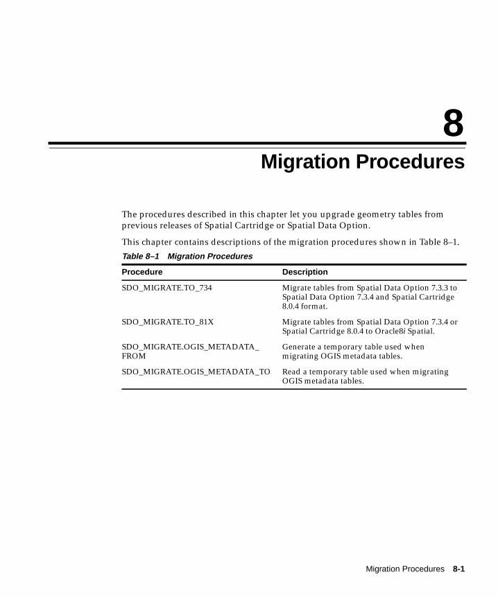
Migration Proc
8
Migration ProceduresThe procedures described in this chapter let you upgrade geometry tables fromprevious releases of Spatial Cartridge or Spatial Data Option.
This chapter contains descriptions of the migration procedures shown in Table 8–1.
Table 8–1 Migration Procedures
Procedure Description
SDO_MIGRATE.TO_734 Migrate tables from Spatial Data Option 7.3.3 toSpatial Data Option 7.3.4 and Spatial Cartridge8.0.4 format.
SDO_MIGRATE.TO_81X Migrate tables from Spatial Data Option 7.3.4 orSpatial Cartridge 8.0.4 to Oracle8i Spatial.
SDO_MIGRATE.OGIS_METADATA_FROM
Generate a temporary table used whenmigrating OGIS metadata tables.
SDO_MIGRATE.OGIS_METADATA_TO Read a temporary table used when migratingOGIS metadata tables.
edures 8-1
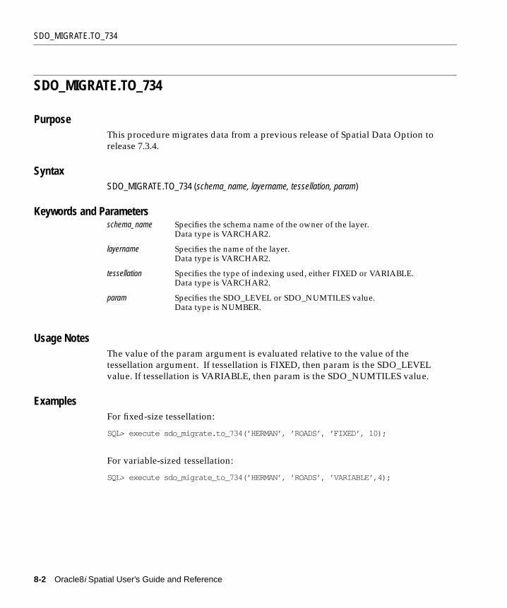
SDO_MIGRATE.TO_734
SDO_MIGRATE.TO_734
PurposeThis procedure migrates data from a previous release of Spatial Data Option torelease 7.3.4.
SyntaxSDO_MIGRATE.TO_734 (schema_name, layername, tessellation, param)
Keywords and Parameters
Usage NotesThe value of the param argument is evaluated relative to the value of thetessellation argument. If tessellation is FIXED, then param is the SDO_LEVELvalue. If tessellation is VARIABLE, then param is the SDO_NUMTILES value.
ExamplesFor fixed-size tessellation:
SQL> execute sdo_migrate.to_734(’HERMAN’, ’ROADS’, ’FIXED’, 10);
For variable-sized tessellation:
SQL> execute sdo_migrate_to_734(’HERMAN’, ’ROADS’, ’VARIABLE’,4);
schema_name Specifies the schema name of the owner of the layer.Data type is VARCHAR2.
layername Specifies the name of the layer.Data type is VARCHAR2.
tessellation Specifies the type of indexing used, either FIXED or VARIABLE.Data type is VARCHAR2.
param Specifies the SDO_LEVEL or SDO_NUMTILES value.Data type is NUMBER.
8-2 Oracle8i Spatial User’s Guide and Reference
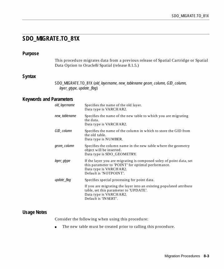
SDO_MIGRATE.TO_81X
SDO_MIGRATE.TO_81X
PurposeThis procedure migrates data from a previous release of Spatial Cartridge or SpatialData Option to Oracle8i Spatial (release 8.1.5.)
SyntaxSDO_MIGRATE.TO_81X (old_layername, new_tablename geom_column, GID_column, layer_gtype, update_flag)
Keywords and Parameters
Usage NotesConsider the following when using this procedure:
■ The new table must be created prior to calling this procedure.
old_layername Specifies the name of the old layer.Data type is VARCHAR2.
new_tablename Specifies the name of the new table to which you are migratingthe data.Data type is VARCHAR2.
GID_column Specifies the name of the column in which to store the GID fromthe old table.Data type is NUMBER.
geom_column Specifies the column name in the new table where the geometryobject will be inserted.Data type is SDO_GEOMETRY.
layer_gtype If the layer you are migrating is composed soley of point data, setthis parameter to ’POINT’ for optimal performance.Data type is VARCHAR2.Default is ’NOTPOINT’.
update_flag Specifies special processing for point data.
If you are migrating the layer into an existing populated attributetable, set this parameter to ’UPDATE’.Data type is VARCHAR2.Default is ’INSERT’.
Migration Procedures 8-3

SDO_MIGRATE.TO_81X
■ This procedure converts from Spatial Data Option release 7.3.4, or from SpatialCartridge releases 8.0.4 and 8.0.5.
■ There is no implicit commit when using this procedure. You must commit themigration explicitly.
■ If any of the migration steps fails, nothing is migrated for the layer.
■ The old_layername is the underlying layername, without the _SDOGEOMsuffix.
■ An SDO_GEOM_METADATA table is required in the user’s schema.
■ The old SDO_GID is stored in GID_column.
ExamplesInsert point-only data into new rows:
execute sdo_migrate.to_81x('raptor', 'raptor', 'sdo_gid', 'feature', 'point');
Insert nonpoint data into new rows:
execute sdo_migrate.to_81x('BTU', 'BTU', 'sdo_gid', 'feature');
Update point-only data into existing rows:
execute sdo_migrate.to_81x('raptor', 'raptor', 'sdo_gid', 'feature', 'point', 'update');
Update nonpoint data into existing rows:
execute sdo_migrate.to_81x('BTU', 'BTU', 'sdo_gid', 'feature', 'notpoint', 'update');
8-4 Oracle8i Spatial User’s Guide and Reference

SDO_MIGRATE.OGIS_METADATA_FROM
SDO_MIGRATE.OGIS_METADATA_FROM
PurposeThis procedure is called at the source database when migrating from one 8.1.5database to another 8.1.5 database. The procedure migrates OGIS metadata entriesfrom schemas owned by mdsys.
SyntaxSDO_MIGRATE.OGIS_METADATA_FROM
Keywords and ParametersNone.
Usage NotesConsider the following when using this procedure:
■ The tables involved are strictly maintained by the user, and not by Spatial.Details are available in the sdocat.sql file and the OpenGIS specification.
■ Call this procedure once before migrating the data, and it will generate atemporary table called SDO_GC_MIG. Export the temporary table to the newdatabase and call SDO_MIGRATE.OGIS_METADATA_TO to restore the data.
Migration Procedures 8-5
SDO_MIGRATE.OGIS_METADATA_TO
SDO_MIGRATE.OGIS_METADATA_TO
PurposeThis procedure is used at the destination database when migrating from one 8.1.5database to another 8.1.5 database. The procedure migrates OGIS metadata entriesfrom schemas owned by mdsys.
SyntaxSDO_MIGRATE.OGIS_METADATA_TO
Keywords and ParametersNone.
Usage NotesConsider the following when using this procedure:
■ The tables involved are strictly maintained by the user, and not by Spatial.Details are available in the sdocat.sql file and the OpenGIS specification.
■ Call this procedure once after migrating the data. See SDO_MIGRATE.OGIS_METADATA_FROM.
8-6 Oracle8i Spatial User’s Guide and Reference

Spatial Op
9
Spatial OperatorsThis chapter describes the operators used when working with the spatial objectdata type. The operators are listed in Table 9–1.
Table 9–1 Spatial Usage Operators
Operator Description
SDO_FILTER Specifies which geometries may interactwith a given geometry.
SDO_RELATE Determines whether or not two geometriesinteract in a specified way.
SDO_WITHIN_DISTANCE Determines if two geometries are within aspecified Euclidean distance from oneanother.
erators 9-1
SDO_FILTER
SDO_FILTER
PurposeThis operator uses the spatial index to identify either the set of spatial objects thatmay spatially interact with a given object (such as an area-of-interest,) or pairs ofspatial objects that might spatially interact. Objects spatially interact if they are notdisjoint. This operator performs only a primary filter operation.
SyntaxSDO_FILTER(geometry1, geometry2, params) ;
Keywords and Parameters
geometry1 Specifies a geometry column in a table. The column must be spatially indexed.Data type is MDSYS.SDO_GEOMETRY.
geometry2 Specifies either a geometry from a table or a transient instance of a geometry.(Specified using a bind variable or SDO_GEOMETRY constructor.)Data type is MDSYS.SDO_GEOMETRY.
PARAMS Determines the behavior of the operator. Data type is VARCHAR2.
Keyword Description
querytype Specifies valid query types: JOIN or WINDOW. This is a required parameter.
WINDOW implies that geometry2 should be considered a dynamic (transient)area-of-interest. Use WINDOW when you want to compare a single geometry(geometry2) to all the geometries in a column (geometry1).
JOIN implies that the second argument refers to a table column that must havea spatial index built on it. Use JOIN when you want to compare all thegeometries of a column to all the geometries of another column.
idxtab1 Not supported in this release. Specifies the name of the index, if there aremultiple spatial indexes, for geometry1.
idxtab2 Not supported in this release. Specifies the name of the index table (if there aremultiple spatial indexes) for geometry2. Only valid for ’querytype = JOIN.’
layer_gtype Specifies special processing for point data.
If the columns you are comparing are comprised soley of point data, set thisparameter to ’POINT’ for optimal performance.Data type is VARCHAR2.Default is ’NOTPOINT’.
9-2 Oracle8i Spatial User’s Guide and Reference

SDO_FILTER
ReturnsThe expression SDO_FILTER(arg1, arg2, arg3) = ‘TRUE’ evaluates to TRUE forobject pairs that are non-disjoint and FALSE otherwise.
Usage Notes■ The operator must always be used in a WHERE clause and the condition that
includes the operator should be an expression of the form SDO_FILTER(arg1,arg2, arg3) = ‘TRUE’.
■ If the querytype is ’WINDOW’, geometry2 can come from a table or be atransient SDO_GEOMETRY object (such as a bind variable or SDO_GEOMETRY constructor). If geometry2 is transient, it is indexed in memory.
If geometry2 comes from a table column that is not spatially indexed,geometry2 is indexed in memory.
If geometry2 comes from a table column that is spatially indexed, geometry2will reuse its index. Performance will degrade if geometry2 is not indexed withthe same sdo_level parameter as geometry1.
Examples1. SELECT A.gid
FROM Polygons A, query_polys B WHERE B.gid = 1 AND SDO_FILTER(A.Geometry, B.Geometry, ’querytype = WINDOW’) = ’TRUE’;
2. SELECT A.gid FROM Polygons A, query_polys B WHERE SDO_FILTER(A.Geometry, B.Geometry, ’querytype = JOIN’) = ’TRUE’;
3. Select A.Gid FROM Polygons A WHERE SDO_FILTER(A.Geometry, :aGeom, ’querytype=WINDOW’) = ’TRUE’;
4. Select A.Gid FROM Polygons A WHERE SDO_FILTER(A.Geometry, mdsys.sdo_geometry(3,NULL,NULL, mdsys.sdo_elem_info(1,3,3), mdsys.sdo_ordinates(x1,y1,x2,y2)), ’querytype=WINDOW’) = ’TRUE’;
Related TopicsSDO_RELATE
Spatial Operators 9-3

SDO_RELATE
SDO_RELATE
PurposeThis operator uses the spatial index to identify either the set of spatial objects thathave a particular spatial interaction with a given object such as an area-of-interest,or pairs of spatial objects that have a particular spatial interaction.
This operator performs both primary and secondary filter operations.
SyntaxSDO_RELATE(geometry1, geometry2, params) ;
Keywords and Parameters
geometry1 Specifies a geometry column in a table. The column must be spatiallyindexed.Data type is MDSYS.SDO_GEOMETRY.
geometry2 Specifies either a geometry from a table or a transient instance of ageometry. (Specified using a bind variable or SDO_GEOMETRYconstructor.)Data type is MDSYS.SDO_GEOMETRY.
PARAMS Determines the behavior of the operator.Data type is VARCHAR2.
Keyword Description
mask Specifies the topological relation of interest. This is a required parameter.
Valid values are one or more of {TOUCH, OVERLAP, EQUAL, INSIDE,COVEREDBY, CONTAINS, COVERS, ANYINTERACT} in the9-intersection pattern. Multiple masks are combined with a the logicalBoolean operator OR as follows: ’mask=(inside+touch)’. See Section 1.7for an explanation of the 9-intersection relationship pattern.
querytype Valid query types are: JOIN or WINDOW. This is a required parameter.
WINDOW implies that geometry2 should be considered a dynamic(transient) area-of-interest. Use WINDOW when you want to compare asingle geometry (geometry2) to all the geometries in a column(geometry1).
JOIN implies that the second argument refers to a table column that musthave a spatial index built on it. Use JOIN when you want to compare allthe geometries of a column to all the geometries of another column.
9-4 Oracle8i Spatial User’s Guide and Reference

SDO_RELATE
ReturnsThe expression SDO_RELATE(geometry1,geometry2, ‘mask = <some_mask_val>querytype = <some_querytype>’) = ‘TRUE’ evaluates to TRUE for object pairs thathave the topological relationship specified by <some_mask_val> and FALSEotherwise.
Usage Notes■ The operator must always be used in a WHERE clause, and the condition that
includes the operator should be an expression of the form SDO_RELATE(arg1,arg2, ‘mask = <some_mask_val> querytype = <some_querytype>’) = ‘TRUE’.
■ If the query type is ’WINDOW’, geometry2 can come from a table or be atransient SDO_GEOMETRY object (such as a bind variable or SDO_GEOMETRY constructor). If geometry2 is transient, it is indexed in memory.
If geometry2 comes from a table column that is not spatially indexed,geometry2 is indexed in memory.
If geometry2 comes from a table column that is spatially indexed, geometry2will re-use its index. Performance will degrade if geometry2 is not indexedwith the same sdo_level parameter as geometry1.
■ Unlike the SDO_GEOM.RELATE function, DISJOINT and DETERMINE masksare not allowed in the relationship mask. This is because SDO_RELATE usesthe spatial index to find candidates that may interact, and the information tosatisfy DISJOINT or DETERMINE is not present in the index.
Examples1. SELECT A.gid
FROM Polygons A, query_polys B
idxtab1 Not supported in this release. Specifies the name of the index, if there aremultiple spatial indexes, for geometry1.
idxtab2 Not supported in this release. Specifies the name of the index, if there aremultiple spatial indexes, for geometry2. Only valid for ’querytype =JOIN’.
layer_gtype Specifies special processing for point data.
If the columns you are comparing are composed soley of point data, setthis parameter to ’POINT’ for optimal performance.Data type is VARCHAR2.Default is ’NOTPOINT’.
Spatial Operators 9-5
SDO_RELATE
WHERE B.gid = 1 AND SDO_RELATE(A.Geometry, B.Geometry, ’mask=ANYINTERACT querytype = WINDOW’) = ’TRUE’;
2. SELECT A.gid FROM Polygons A, query_polys B WHERE SDO_RELATE(A.Geometry, B.Geometry, ’mask=ANYINTERACT querytype = JOIN’) = ’TRUE’;
3. Select A.Gid FROM Polygons A WHERE SDO_RELATE(A.Geometry, :aGeom, ’mask=ANYINTERACT querytype=WINDOW’) = ’TRUE’;
4. Select A.Gid FROM Polygons A WHERE SDO_RELATE(A.Geometry, mdsys.sdo_geometry(3,NULL,NULL, mdsys.sdo_elem_info(1,3,3), mdsys.sdo_ordinates(x1,y1,x2,y2)), ’mask=ANYINTERACT querytype=WINDOW’) = ’TRUE’;
Related Topics■ SDO_FILTER
■ SDO_WITHIN_DISTANCE
■ SDO_GEOM.RELATE( )
9-6 Oracle8i Spatial User’s Guide and Reference

SDO_WITHIN_DISTANCE
SDO_WITHIN_DISTANCE
PurposeThis operator uses the spatial index to identify the set of spatial objects that arewithin some specified Euclidean distance of a given object (such as an area orpoint-of-interest.)
SyntaxSDO_WITHIN_DISTANCE(T.column, aGeom, params) ;
Keywords and Parameters
T.column Specifies a geometry column in a table. The column must be spatiallyindexed.Data type is MDSYS.SDO_GEOMETRY.
aGeom Specifies either a geometry from a table or a transient instance of ageometry. (Specified using a bind variable or SDO_GEOMETRYconstructor.)Data type is MDSYS.SDO_GEOMETRY.
PARAMS Determines the behavior of the operator.Data type is VARCHAR2.
Keyword Description
distance Specifies the Euclidean distance value. This is a required parameter.Data type is NUMBER.
idxtab1 Not supported in this release. Specifies the name of the index if thereare multiple spatial index tables for geometry1.
querytype Set ’querytype=FILTER’ to perform only a primary filter operation. Ifquerytype is not specified, both primary and secondary filteroperations are performed (default).Data type is VARCHAR2.
layer_gtype Specifies special processing for point data.
If the columns you are comparing are composed soley of point data,set this parameter to ’POINT’ for optimal performance.Data type is VARCHAR2.Default is ’NOTPOINT’.
Spatial Operators 9-7

SDO_WITHIN_DISTANCE
ReturnsThe expression SDO_WITHIN_DISTANCE(arg1, arg2, arg3) = ‘TRUE’ evaluates toTRUE for object pairs that are within the specified distance, and FALSE otherwise.
Usage Notes■ Distance between two extended objects (nonpoint objects such as lines and
polygons) is defined as the minimum distance between these two objects. Thedistance between two adjacent polygons is zero.
■ The operator must always be used in a WHERE clause and the condition thatincludes the operator should be an expression of the form:
SDO_WITHIN_DISTANCE(arg1, arg2, ’distance = <some_dist_val>’) = ‘TRUE’
■ T.column must have a spatial index built on it.
■ SDO_WITHIN_DISTANCE( ) is not supported for spatial joins. SeeSection 4.2.3 for a discussion on how to perform a spatial join within-distanceoperation.
Examples1. SELECT A.GID
FROM POLYGONS A WHERE SDO_WITHIN_DISTANCE(A.Geometry, :aGeom, ’distance = 10’) = ’TRUE’ ;
2. SELECT A.GID FROM POLYGONS A WHERE SDO_WITHIN_DISTANCE(A.Geometry, mdsys.sdo_geometry(3,NULL,NULL, mdsys.sdo_elem_info(1,3,3), mdsys.sdo_ordinates(x1,y1,x2,y2)), ’distance = 10’) = ’TRUE’ ;
3. SELECT A.GID FROM POLYGONS A, Query_Points B WHERE B.GID = 1 AND SDO_WITHIN_DISTANCE(A.Geometry, B.Geometry, ’distance = 10’) = ’TRUE’ ;
Related Topics■ SDO_RELATE
■ SDO_FILTER
9-8 Oracle8i Spatial User’s Guide and Reference

Part II
Relational ModelOracle8i Spatial supports two models for representing geometries: relational andobject-relational. The two models are mutually exclusive. See Appendix A for adescription of how to choose the model best suited for your application.
This part of the User’s Guide and Reference contains the following chapters,describing the relational model:
■ Chapter 10, "The Relational Schema"
■ Chapter 11, "Loading Spatial Data"
■ Chapter 12, "Querying Spatial Data"
■ Chapter 13, "Administrative Functions and Procedures"
■ Chapter 14, "Tuning Functions and Procedures"
■ Chapter 15, "Geometry Functions and Procedures"
■ Chapter 16, "Window Functions and Procedures"


The Relational S
10
The Relational SchemaPrior to release 8.1, the Spatial product always used four database tables to storeand index spatial data. This database structure is modeled on the first of threeOpen GIS Features for SQL Implementation options, namely, using numeric SQLtypes for geometry storage. This schema is different from the new spatial objectsmodel introduced in Spatial release 8.1 and described in Part II of this guide.However there are still some advantages, discussed in Section A.1, to using thismodel.
10.1 Database Structures for the Relational ImplementationThe four tables, used to store and index geometry, are collectively referred to as alayer. A template SQL script is provided to facilitate the creation of these tables. SeeSection A.3.2, "crlayer.sql Script" for details.
Table 10–1 through Table 10–4 describe the schema of a Spatial layer.
Table 10–1 <layername>_SDOLAYER
Table 10–2 <layername>_SDODIM Table or View
1 SDO_MAXLEVEL is an optional column.2 SDO_COORDSYS is an optional column.
SDO_ORDCNT SDO_LEVEL SDO_NUMTILES SDO_MAXLEVEL 1 SDO_COORDSYS2
<number> <number> <number> <number> <varchar>
SDO_DIMNUM SDO_LB SDO_UB SDO_TOLERANCE SDO_DIMNAME
<number> <number> <number> <number> <varchar>
chema 10-1

Database Structures for the Relational Implementation
Table 10–3 <layername>_SDOGEOM Table or View
Table 10–4 <layername>_SDOINDEX Table
The columns of each table are defined as follows:
<layername>_SDOLAYER:■ SDO_ORDCNT - The SDO_ORDCNT column is the total number of
ordinates per row in the <layername>_SDOGEOM table. That is, the totalnumber of data value columns, and not the number of points orcoordinates. SDO_ORDCNT should not be multiplied by the total numberof dimensions per coordinate as it is already a total.
■ SDO_LEVEL - The SDO_LEVEL column stores the number of times the tilesthat interact with a geometry should be decomposed. It is the terminationcriteria for fixed tiling. Use the SDO_TUNE.ESTIMATE_TILING_LEVELprocedure to determine an appropriate tiling level for your data.
■ SDO_NUMTILES - The SDO_NUMTILES column is the number ofvariable-sized tiles used to tessellate each object in the <layername>_SDOGEOM table. This column must be set to NULL when using fixed-sizetiles.
■ SDO_MAXLEVEL - The SDO_MAXLEVEL column indicates the maximumlevel to which a variable-sized tile can be decomposed. It is the terminationcriteria for the variable component of hybrid tiling.
■ SDO_COORDSYS - The SDO_COORDSYS column is optional; where youcan indicate the name of the coordinate system, using a standard such asPOSC or OGIS.
1 SDO_MAXCODE is not required for the recommended fixed-size tile indexing algorithm.2 SDO_GROUPCODE is not required for the recommended fixed-size tile indexing algorithm.
SDO_GID SDO_ESEQ SDO_ETYPE SDO_SEQ SDO_X1 SDO_Y1 ... SDO_Xn SDO_Yn
<number> <number> <number> <number> <number> <number> ... <number> <number>
SDO_GID SDO_CODE SDO_MAXCODE 1 SDO_GROUPCODE 2 SDO_META
<number> <raw> <raw> <raw> <raw>
10-2 Oracle8i Spatial User’s Guide and Reference

Database Structures for the Relational Implementation
<layername>_SDODIM:■ SDO_DIMNUM - The SDO_DIMNUM column is the dimension to which this
row refers, starting with 1 and increasing.
■ SDO_LB - The SDO_LB column is the lower bound of the ordinate in thisdimension. For example, if the dimension is latitude, the lower boundwould be -90.
■ SDO_UB - The SDO_UB column is the upper bound of the ordinate in thisdimension. For example, if the dimension is latitude, the upper boundwould be 90.
■ SDO_TOLERANCE - The SDO_TOLERANCE column is the distance twopoints can be apart and still be considered the same due to round-offerrors. Tolerance must be greater than zero. If you want zero tolerance,enter a number such as 0.00005, where the number of zeroes to the right ofthe decimal point matches the precision of your data. The extra 5 willround up to your last decimal digit.
■ SDO_DIMNAME - The SDO_DIMNAME column is used for the usual nameapplied to this dimension, such as longitude, latitude, X or Y.
<layername>_SDOGEOM:■ SDO_GID - The SDO_GID column is a unique numeric identifier for each
geometry in a layer.
■ SDO_ESEQ - The SDO_ESEQ column enumerates each element in ageometry, that is, the Element SEQuence number.
■ SDO_ETYPE - The SDO_ETYPE column is the geometric primitive type ofthe element. For this release of Spatial, the valid values are SDO_GEOM.POINT_TYPE, SDO_GEOM.LINESTRING_TYPE, or SDO_GEOM.POLYGON_TYPE (ETYPE values 1, 2, and 3, respectively). TheSDO_ETYPE values 4 and 5, supported in the object-relational schema, arenot supported. Setting the ETYPE to zero indicates that this element shouldbe ignored. See Section A.2.8 for information on ETYPE=0.
■ SDO_SEQ - The SDO_SEQ column records the order (the SEQuencenumber) of each row of data making up the element.
■ SDO_X1 - X value of the first coordinate.
■ SDO_Y1 - Y value of the first coordinate.
■ SDO_Xn - X value of the Nth coordinate.
The Relational Schema 10-3

Database Structures for the Relational Implementation
■ SDO_Yn - Y value of the Nth coordinate.
<layername>_SDOINDEX:■ SDO_GID - The SDO_GID column is a unique numeric identifier for each
geometry in a layer. This can be thought of as a foreign key back to the<layername>_SDOGEOM table.
■ SDO_CODE- The SDO_CODE column is the bit-interleaved ID of a tile thatcovers SDO_GID. This column should be created as type RAW(255).
■ SDO_MAXCODE - The SDO_MAXCODE column describes a variable-sizedlogical tile, which is the smallest tile (with the longest tile ID) in the currentquadrant. The SDO_MAXCODE column is SDO_CODE padded out oneplace farther than the longest allowable code name for this index. Thiscolumn is not used for fixed-size tiles.
■ SDO_GROUPCODE -The SDO_GROUPCODE column is a prefix of SDO_CODE. It represents a variable-sized tile at level <layername>_SDOLAYER.SDO_LEVEL that contains or is equal to the tile represented bySDO_CODE. This column is not used for fixed-size tiles.
■ SDO_META- The SDO_META column is not required for spatial queries. Itprovides information necessary to find the bounds of a tile. SeeSection A.2.4 for one possible use of this column.
Spatial provides stored procedures that assume the existence of the layer schema asdescribed in this section. While layer tables may contain additional columns, theyare required to contain at least the columns described in this section with the samecolumn names and data types.
Figure 10–1 illustrates how a geometry is stored in the database using Spatial andthe OGIS V1 schema model. The geometry to be stored is a complex polygon with ahole in it.
10-4 Oracle8i Spatial User’s Guide and Reference
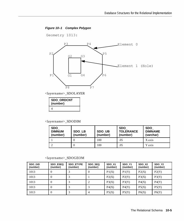
Database Structures for the Relational Implementation
Figure 10–1 Complex Polygon
<layername>_SDOLAYER
<layername>_SDODIM
<layername>_SDOGEOM
SDO_ORDCNT(number)
4
SDO_DIMNUM(number)
SDO_LB(number)
SDO_UB(number)
SDO_TOLERANCE(number)
SDO_DIMNAME(varchar)
1 0 100 .05 X axis
2 0 100 .05 Y axis
SDO_GID(number)
SDO_ESEQ(number)
SDO_ETYPE(number)
SDO_SEQ(number)
SDO_X1(number)
SDO_Y1(number)
SDO_X2(number)
SDO_Y2(number)
1013 0 3 0 P1(X) P1(Y) P2(X) P2(Y)
1013 0 3 1 P2(X) P2(Y) P3(X) P3(Y)
1013 0 3 2 P3(X) P3(Y) P4(X) P4(Y)
1013 0 3 3 P4(X) P4(Y) P5(X) P5(Y)
1013 0 3 4 P5(X) P5(Y) P6(X) P6(Y)
G2 G3
G4G1
P3 P4
P5
P6
P7P8
P1
P2
Element 0
Element 1 (Hole)
Geometry 1013:
The Relational Schema 10-5

Database Structures for the Relational Implementation
In this example, the <layername>_SDOGEOM table is shown as an 8-column tablewith 4 ordinates per row. In actual usage, Spatial supports N-wide1 tables. Thecoordinates for the outer polygon in this example could have been loaded into asingle row containing values for coordinates P1 to P8, and then repeating P1 toclose the polygon. The coordinates would be stored in the SDO_X1 and SDO_Y1through SDO_X9 and SDO_Y9 columns.
The data in the <layername>_SDOINDEX table is described in further detailSection 1.6, “Indexing Methods”. The SDOINDEX table contains entries of the form[SDO_GID, SDO_CODE] where each SDO_CODE represents a tile that interactswith a geometry identified by SDO_GID. For a given SDO_GID value, there may beone or more SDO_CODEs. Each SDO_CODE value may be associated with one ormore SDO_GIDs.
1 A <layername>_SDOGEOM table can have up to 1000 columns. The maximum numberof data columns is 1000, minus 4 for the other required spatial columns, and minus anyother user-defined columns. For polygons and line strings, storing 16 to 20 ordinates perrow is suggested for performance reasons, but not required. The objective is to minimizethe number of NULLs stored in the <layername>_SDOGEOM table.
1013 0 3 5 P6(X) P6(Y) P7(X) P7(Y)
1013 0 3 6 P7(X) P7(Y) P8(X) P8(Y)
1013 0 3 7 P8(X) P8(Y) P1(X) P1(Y)
1013 1 3 0 G1(X) G1(Y) G2(X) G2(Y)
1013 1 3 1 G2(X) G2(Y) G3(X) G3(Y)
1013 1 3 2 G3(X) G3(Y) G4(X) G4(Y)
1013 1 3 3 G4(X) G4(Y) G1(X) G1(Y)
SDO_GID(number)
SDO_ESEQ(number)
SDO_ETYPE(number)
SDO_SEQ(number)
SDO_X1(number)
SDO_Y1(number)
SDO_X2(number)
SDO_Y2(number)
10-6 Oracle8i Spatial User’s Guide and Reference
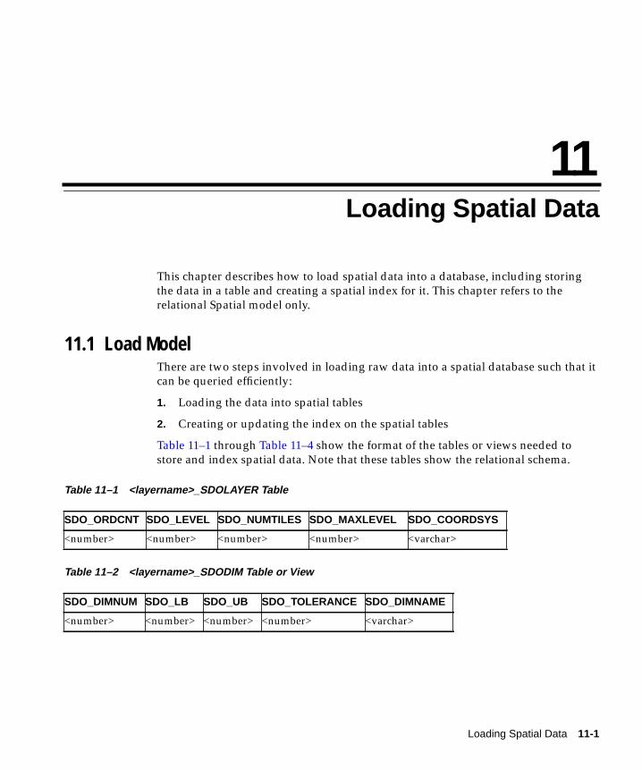
Loading Spatia
11
Loading Spatial DataThis chapter describes how to load spatial data into a database, including storingthe data in a table and creating a spatial index for it. This chapter refers to therelational Spatial model only.
11.1 Load ModelThere are two steps involved in loading raw data into a spatial database such that itcan be queried efficiently:
1. Loading the data into spatial tables
2. Creating or updating the index on the spatial tables
Table 11–1 through Table 11–4 show the format of the tables or views needed tostore and index spatial data. Note that these tables show the relational schema.
Table 11–1 <layername>_SDOLAYER Table
Table 11–2 <layername>_SDODIM Table or View
SDO_ORDCNT SDO_LEVEL SDO_NUMTILES SDO_MAXLEVEL SDO_COORDSYS
<number> <number> <number> <number> <varchar>
SDO_DIMNUM SDO_LB SDO_UB SDO_TOLERANCE SDO_DIMNAME
<number> <number> <number> <number> <varchar>
l Data 11-1
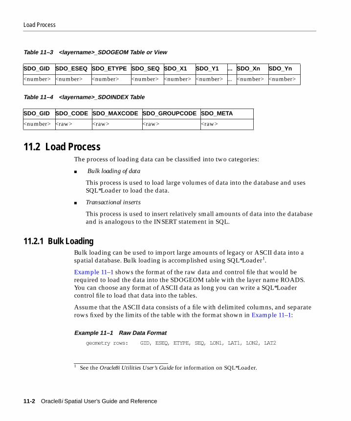
Load Process
Table 11–3 <layername>_SDOGEOM Table or View
Table 11–4 <layername>_SDOINDEX Table
11.2 Load ProcessThe process of loading data can be classified into two categories:
■ Bulk loading of data
This process is used to load large volumes of data into the database and usesSQL*Loader to load the data.
■ Transactional inserts
This process is used to insert relatively small amounts of data into the databaseand is analogous to the INSERT statement in SQL.
11.2.1 Bulk LoadingBulk loading can be used to import large amounts of legacy or ASCII data into aspatial database. Bulk loading is accomplished using SQL*Loader1.
Example 11–1 shows the format of the raw data and control file that would berequired to load the data into the SDOGEOM table with the layer name ROADS.You can choose any format of ASCII data as long you can write a SQL*Loadercontrol file to load that data into the tables.
Assume that the ASCII data consists of a file with delimited columns, and separaterows fixed by the limits of the table with the format shown in Example 11–1:
Example 11–1 Raw Data Format
geometry rows: GID, ESEQ, ETYPE, SEQ, LON1, LAT1, LON2, LAT2
1 See the Oracle8i Utilities User’s Guide for information on SQL*Loader.
SDO_GID SDO_ESEQ SDO_ETYPE SDO_SEQ SDO_X1 SDO_Y1 ... SDO_Xn SDO_Yn
<number> <number> <number> <number> <number> <number> ... <number> <number>
SDO_GID SDO_CODE SDO_MAXCODE SDO_GROUPCODE SDO_META
<number> <raw> <raw> <raw> <raw>
11-2 Oracle8i Spatial User’s Guide and Reference

Load Process
The coordinates in the geometry rows represent the end points of line segments,which taken together, represent a polygon. Example 11–2 shows the control file forloading the data into the geometry table.
Example 11–2 Control File to Load Data into the Geometry Table
LOAD DATA INFILE *INTO TABLE ROADS_SDOGEOMFIELDS TERMINATED BY WHITESPACE TRAILING NULLCOLS(SDO_GID INTEGER EXTERNAL,SDO_ESEQ INTEGER EXTERNAL,SDO_ETYPE INTEGER EXTERNAL,SDO_SEQ INTEGER EXTERNAL,SDO_X1 FLOAT EXTERNAL,SDO_Y1 FLOAT EXTERNAL,SDO_X2 FLOAT EXTERNAL,SDO_Y2 FLOAT EXTERNAL)
BEGINDATA1 0 3 0 -122.401200 37.805200 -122.401900 37.8052001 0 3 1 -122.401900 37.805200 -122.402400 37.8055001 0 3 2 -122.402400 37.805500 -122.403100 37.8060001 0 3 3 -122.403100 37.806000 -122.404400 37.8068001 0 3 4 -122.404400 37.806800 -122.401200 37.8052001 1 3 0 -122.405900 37.806600 -122.407549 37.8063941 1 3 1 -122.407549 37.806394 -122.408300 37.8063001 1 3 2 -122.408300 37.806300 -122.409100 37.8062001 1 3 3 -122.409100 37.806200 -122.405900 37.8066002 0 2 0 -122.410800 37.806000 -122.412300 37.8058002 0 2 1 -122.412300 37.805800 -122.414100 37.8056002 0 2 2 -122.414100 37.805600 -122.412300 37.8058002 0 2 3 -122.412300 37.805800 -122.410800 37.8060003 0 1 0 -122.567474 38.6435643 0 1 1 -126.345345 39.345345
Note that table ROADS_SDOGEOM exists in the schema before attempting theload.
In Example 11–3, the data resides in a single flat file and the data set consists ofpoint, line string, and polygon data. The data uses fixed-position columns andoverloaded table rows.
Example 11–3 Raw Data Format
SDO_GID SDO_ESEQ SDO_ETYPE SDO_SEQ SDO_X1 SDO_Y1 SDO_X2 SDO_Y2
Loading Spatial Data 11-3
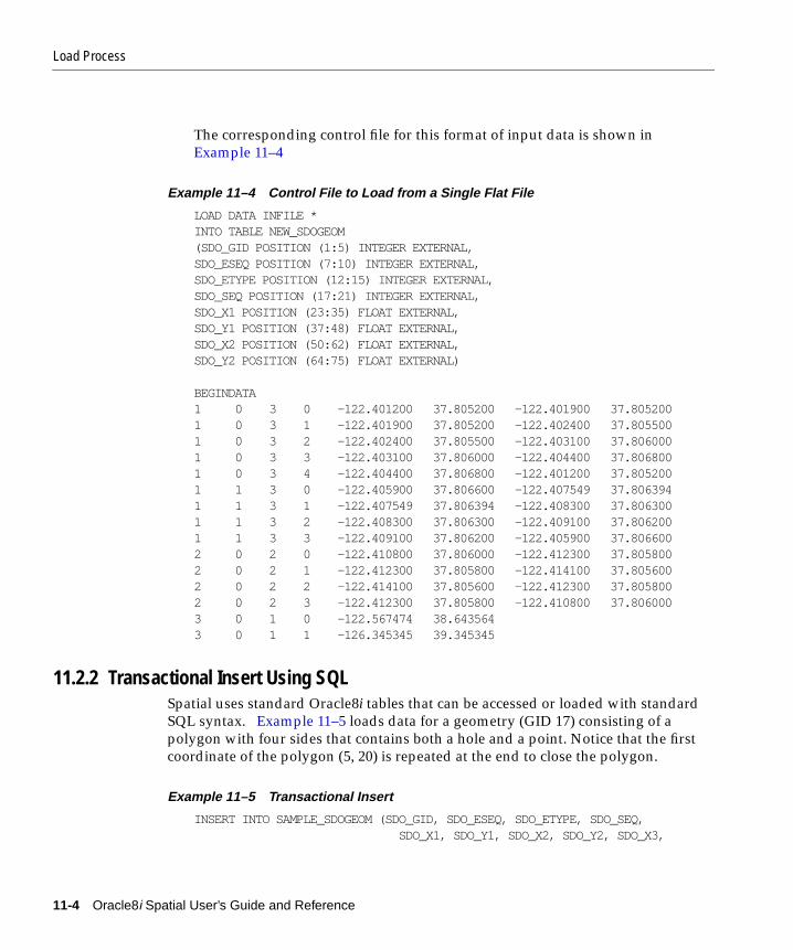
Load Process
The corresponding control file for this format of input data is shown inExample 11–4
Example 11–4 Control File to Load from a Single Flat File
LOAD DATA INFILE *INTO TABLE NEW_SDOGEOM(SDO_GID POSITION (1:5) INTEGER EXTERNAL,SDO_ESEQ POSITION (7:10) INTEGER EXTERNAL,SDO_ETYPE POSITION (12:15) INTEGER EXTERNAL,SDO_SEQ POSITION (17:21) INTEGER EXTERNAL,SDO_X1 POSITION (23:35) FLOAT EXTERNAL,SDO_Y1 POSITION (37:48) FLOAT EXTERNAL,SDO_X2 POSITION (50:62) FLOAT EXTERNAL,SDO_Y2 POSITION (64:75) FLOAT EXTERNAL)
BEGINDATA1 0 3 0 -122.401200 37.805200 -122.401900 37.8052001 0 3 1 -122.401900 37.805200 -122.402400 37.8055001 0 3 2 -122.402400 37.805500 -122.403100 37.8060001 0 3 3 -122.403100 37.806000 -122.404400 37.8068001 0 3 4 -122.404400 37.806800 -122.401200 37.8052001 1 3 0 -122.405900 37.806600 -122.407549 37.8063941 1 3 1 -122.407549 37.806394 -122.408300 37.8063001 1 3 2 -122.408300 37.806300 -122.409100 37.8062001 1 3 3 -122.409100 37.806200 -122.405900 37.8066002 0 2 0 -122.410800 37.806000 -122.412300 37.8058002 0 2 1 -122.412300 37.805800 -122.414100 37.8056002 0 2 2 -122.414100 37.805600 -122.412300 37.8058002 0 2 3 -122.412300 37.805800 -122.410800 37.8060003 0 1 0 -122.567474 38.6435643 0 1 1 -126.345345 39.345345
11.2.2 Transactional Insert Using SQLSpatial uses standard Oracle8i tables that can be accessed or loaded with standardSQL syntax. Example 11–5 loads data for a geometry (GID 17) consisting of apolygon with four sides that contains both a hole and a point. Notice that the firstcoordinate of the polygon (5, 20) is repeated at the end to close the polygon.
Example 11–5 Transactional Insert
INSERT INTO SAMPLE_SDOGEOM (SDO_GID, SDO_ESEQ, SDO_ETYPE, SDO_SEQ, SDO_X1, SDO_Y1, SDO_X2, SDO_Y2, SDO_X3,
11-4 Oracle8i Spatial User’s Guide and Reference

Load Process
SDO_Y3, SDO_X4, SDO_Y4, SDO_X5, SDO_Y5) VALUES (17, 0, 3, 0, 5, 20, 5, 30, 10, 30, 10, 20, 5, 20);
-- holeINSERT INTO SAMPLE_SDOGEOM (SDO_GID, SDO_ESEQ, SDO_ETYPE, SDO_SEQ, SDO_X1, SDO_Y1, SDO_X2, SDO_Y2, SDO_X3, SDO_Y3, SDO_X4, SDO_Y4, SDO_X5, SDO_Y5) VALUES (17, 1, 3, 0, 8, 21, 8, 24, 9, 24, 9, 21, 8, 21);
-- pointINSERT INTO SAMPLE_SDOGEOM (SDO_GID, SDO_ESEQ, SDO_ETYPE, SDO_SEQ, SDO_X1, SDO_Y1) VALUES (17, 2, 1, 0, 9, 29);
The SQL INSERT statement inserts one row of data per call. In Example 11–5, thetable had enough columns to store the polygon in a single row. However, if yourtable had fewer columns (or your polygon had more points), you would have toperform multiple inserts in order to match the table structure; the data would notwrap automatically to the next row. To load a large geometry, repeat the SDO_GID,SDO_ESEQ, and SDO_ETYPE, and increment the SDO_SEQ for each line as shownin Example 11–6.
Example 11–6 Transactional Insert for a Large Geometry
INSERT INTO SAMPLE2_SDOGEOM (SDO_GID, SDO_ESEQ, SDO_ETYPE, SDO_SEQ, SDO_X1, SDO_Y1, SDO_X2, SDO_Y2, SDO_X3, SDO_Y3, SDO_X4, SDO_Y4, SDO_X5, SDO_Y5) VALUES (18, 0, 3, 0, 1, 15, 1, 16, 2, 17, 3, 17, 4, 18);
INSERT INTO SAMPLE2_SDOGEOM (SDO_GID, SDO_ESEQ, SDO_ETYPE, SDO_SEQ, SDO_X1, SDO_Y1, SDO_X2, SDO_Y2, SDO_X3, SDO_Y3, SDO_X4, SDO_Y4, SDO_X5, SDO_Y5) VALUES (18, 0, 3, 1, 4, 18, 5, 18, 6, 19, 7, 18, 6, 17);
INSERT INTO SAMPLE2_SDOGEOM (SDO_GID, SDO_ESEQ, SDO_ETYPE, SDO_SEQ, SDO_X1, SDO_Y1, SDO_X2, SDO_Y2, SDO_X3, SDO_Y3, SDO_X4, SDO_Y4, SDO_X5, SDO_Y5) VALUES (18, 0, 3, 2, 6, 17, 7, 16, 7, 15, 6, 14, 7, 13);
INSERT INTO SAMPLE2_SDOGEOM (SDO_GID, SDO_ESEQ, SDO_ETYPE, SDO_SEQ, SDO_X1, SDO_Y1, SDO_X2, SDO_Y2, SDO_X3, SDO_Y3, SDO_X4, SDO_Y4, SDO_X5, SDO_Y5) VALUES (18, 0, 3, 3, 7, 13, 6, 12, 5, 13, 4, 13, 3, 14);
Loading Spatial Data 11-5

Index Creation
INSERT INTO SAMPLE2_SDOGEOM (SDO_GID, SDO_ESEQ, SDO_ETYPE, SDO_SEQ, SDO_X1, SDO_Y1, SDO_X2, SDO_Y2, SDO_X3, SDO_Y3) VALUES (18, 0, 3, 4, 3, 14, 2, 14, 1, 15);
11.3 Index CreationOnce data has been loaded into the spatial tables through either bulk ortransactional loading, a spatial index needs to be created on the tables for efficientaccess to the data.
Create an Oracle table called <layername>_SDOINDEX as follows:
SQL> create table <layername>_SDOINDEX 2 ( 3 SDO_GID number, 4 SDO_CODE raw(255) 5 );
For a bulk load, you can call the SDO_ADMIN.POPULATE_INDEX() procedureonce to tessellate the geometry table and add the generated tiles to the spatial indextable. The argument to this procedure is simply the name of the layer. The level towhich the geometry should be tessellated and whether to use the fixed or thehybrid indexing technique is determined by values in the <layername>_SDOLAYER table.
If data is updated in or deleted from a specific geometry table, you can call SDO_ADMIN.UPDATE_INDEX() to update the index for one SDO_GID. The argumentsto this procedure are the name of the layer and the SDO_GID of the designatedgeometry.
See Chapter 13, "Administrative Functions and Procedures" for a completedescription of the SDO_ADMIN.POPULATE_INDEX() and SDO_ADMIN.UPDATE_INDEX() procedures.
11.3.1 Choosing a Tessellation AlgorithmSpatial provides two methods for spatial indexing, fixed and hybrid. Fixedindexing is recommended for the relational Spatial model.
Which tessellation algorithm is used by the SDO_ADMIN.POPULATE_INDEX() andSDO_ADMIN.UPDATE_INDEX() procedures is determined by the values of the
11-6 Oracle8i Spatial User’s Guide and Reference

Index Creation
SDO_LEVEL and SDO_NUMTILES columns in the <layername>_SDOLAYER tableas shown inTable 11–5.
11.3.2 Spatial Indexing with Fixed-Size TilesOracle recommends using fixed-size cover tiles for indexing a geometry storedusing the relational model.
The fixed-size tile algorithm is expressed as a level referring to the number oftessellations performed. To use fixed-size tile indexing, set the SDO_NUMTILEScolumn in the <layername>_SDOLAYER table to NULL and the SDO_LEVELcolumn to the desired tiling level. The relationship between the tiling level and theresulting size of the tiles is dependent on the domain of the layer.
The domain used for indexing is defined by the upper and lower boundaries ofeach dimension stored in the <layername>_SDODIM table. A typical domain in aGIS application could be -90 to 90 degrees for latitude, and -180 to 180 degrees forlongitude1, as represented in Figure 11–1.
1 The transference of the domain onto a sphere or Mercator projection is left to GIS (orother) application programmers. Spatial treats the domain as a conventional X by Yrectangle.
Table 11–5 Choosing a Tessellation Algorithm
SDO_LEVEL SDO_NUMTILES Action
NULL NULL Error.
>= 1 NULL Fixed indexing with fixed-size tiles(recommended).
>= 1 >= 1 Hybrid indexing with fixed-size andvariable-sized tiles. The SDO_LEVEL columndefines the fixed tile size. The SDO_NUMTILEScolumn defines the number of tiles to generate pergeometry.
NULL >= 1 Not supported.
Loading Spatial Data 11-7

Index Creation
Figure 11–1 Sample GIS Domain
If the SDO_LEVEL column is set to 1, then the tiles created by the indexingmechanism are the same size as tiles at the first level of tessellation. Each tile wouldbe 180 degrees by 90 degrees as shown in Figure 11–2.
Figure 11–2 Fixed-Size Tiling at Level 1
The formula for the number of fixed-size tiles is 4n where n is the number oftessellations, stored in the SDO_LEVEL column. Figure 11–3 shows fixed-size tilingat level 2. In this figure, each tile is 90 degrees by 45 degrees.
-180 180
90
-90
-180 0 180
90
-90
0
11-8 Oracle8i Spatial User’s Guide and Reference

Index Creation
Figure 11–3 Fixed-Size Tiling at Level 2
The size of a tile can be determined by applying the following formula to eachdimension:
length = (upper_bound - lower_bound) / 2 ^ sdo_level
The length refers to the length of the tile along the specified dimension. Applyingthis formula to the tiling shown in Figure 11–3 yields the following sizes:
length for dimension X = (180 - (-180) ) / 2̂ 2 = (360) / 4 = 90length for dimension Y = (90 - (-90) ) / 2̂ 2 = (180) / 4 = 45
Thus, at level 2 the tiles are 90x45 degrees in size. As the number of levels increases,the tiles become smaller and smaller. Smaller tiles provide a more precise fit of thetiles over the geometry being indexed. However, because the number of tilesgenerated is unbounded, you must take into account the performance implicationsof using higher levels. The SDO_TUNE.ESTIMATE_TILING_LEVEL() functioncan be used to determine an appropriate level for indexing with fixed-size tiles. SeeChapter 14 for a description of this procedure.
Besides the performance aspects related to selecting a fixed-size tile, tessellating thegeometry into fixed-size tiles might have benefits related to the type of data beingstored, such as using tiles sized to represent 1-acre farm plots, city blocks, orindividual pixels on a display. Data modeling is an important part any databasedesign, and is essential in a spatial database where the data often represents actualphysical locations.
-180 -90 0 90 180
90
-90
0
Loading Spatial Data 11-9
Index Creation
In the following example, assume that data has been loaded into a layer calledROADS, and you want to create a spatial index on that data. This is accomplishedby first creating a table ROADS_SDOINDEX and invoking the following procedure:
sdo_admin.populate_index(’ROADS’);
The value in the SDO_LEVEL column of the ROADS_SDOLAYER table can be usedas a tuning parameter while tessellating objects. Increasing the level increases thenumber of tiles to provide a more precise fit of the tiles over the object. See thedescription of the ESTIMATE_TILING_LEVEL() function in Chapter 14 forinformation on estimating the tiling level in several different ways.
After the SDO_ADMIN.POPULATE_INDEX() procedure has been called to fill thespatial index, you should also create a concatenated index using the SDO_CODEand SDO_GID columns. The concatenated index helps the join to the <layername>_SDOGEOM table during a query. The SDO_GID values from the primary filter willcome from the index instead of from the table.
If a geometry with an SDO_GID 5944 has been added to the spatial tables, updatethe index with the following procedure:
sdo_admin.update_index(’ROADS’, 5944);
Like the CREATE INDEX statement in SQL, the SDO_ADMIN.POPULATE_INDEX()procedure performs an implicit commit. The SDO_ADMIN.UPDATE_INDEX()procedure, however, does not. Therefore, SDO_ADMIN.UPDATE_INDEX()transactions can be rolled back.
The SDO_ADMIN.POPULATE_INDEX() procedure operates as a single transaction.To reduce the amount of rollback space required to execute this procedure, you canwrite a routine that loops and calls SDO_ADMIN.UPDATE_INDEX(). SeeSection A.3.1, "cr_spatial_index.sql Script" for more information.
11.3.3 Hybrid Spatial Indexing with Fixed-Size and Variable-Sized TilesThis section describes a variation on the linear quadtree (Morton encoding) schemethat uses both fixed-size and variable-sized tiles as a spatial indexing mechanism.the terms hybrid indexing, hybrid tiling, and hybrid tessellation will be usedinterchangeably in this section. Spatial indexing with purely variable-sized tiles isnot recommended for production systems and is not supported in this release.
To use hybrid tiling, the SDO_LEVEL and SDO_NUMTILES columns in the<layername>_SDOLAYER table must contain valid values. That is, both SDO_LEVEL and SDO_NUMTILES must be greater than one.
11-10 Oracle8i Spatial User’s Guide and Reference

Index Creation
The SDO_NUMTILES column determines the number of tiles that will be used tocover a geometry being indexed. Typically, this value is small, such as 4 or 8 tiles.However, the larger the number of tiles, the better the tiles will fit the geometrybeing covered. This increases the selectivity of the primary filter, but also increasesthe number of index entries per geometry (See Section 12.3.2 and Section 12.3.3 fora discussion of primary and secondary filters.) The SDO_NUMTILES value shouldbe larger for long linear spatial entities, such as major highways or rivers, than forarea-based spatial entities such as county or state boundaries.
The SDO_LEVEL column determines the size of the fixed tiles used in hybridindexing. Setting the proper SDO_LEVEL value may appear more like art thanscience. Performing some simple data analysis and testing, however, puts theprocess back in the realm of science. One approach would be use the SDO_TUNE.ESTIMATE_TILING_LEVEL() function to determine an appropriatestarting SDO_LEVEL value, and then compare the performance with slightlyhigher or lower values. This, and other techniques, are described in Appendix A.
Assume that the ROADS layer has already been loaded. Furthermore, assume thatthe there is one row with valid values for the ROADS_SDOLAYER.SDO_LEVELand ROADS_SDOLAYER.SDO_NUMTILES columns. To create the spatial index onROADS, first create a table ROADS_SDOINDEX with appropriate columns:
SQL> create table <layername>_SDOINDEX 2 ( 3 SDO_GID number, 4 SDO_CODE raw(255), 5 SDO_GROUPCODE raw(255), 6 SDO_MAXCODE raw(20), 7 SDO_META raw(255), 8 );
Then, invoke SDO_ADMIN.POPULATE_INDEX(’ROADS’) to build the spatialindex.
After the SDO_ADMIN.POPULATE_INDEX() procedure has been called to fill thespatial index, you should also create a concatenated index on the SDO_CODE andSDO_GID columns. The concatenated index helps the join to the<layername>_SDOGEOM table during a query. The SDO_GID values from theprimary filter will come from the index instead of from the table.
If a geometry with an SDO_GID 5944 has been added to the spatial tables, updatethe index with the following procedure:
sdo_admin.update_index(’ROADS’, 5944);
Loading Spatial Data 11-11

Index Creation
Like the CREATE INDEX statement in SQL, the SDO_ADMIN.POPULATE_INDEX()procedure performs an implicit commit. The SDO_ADMIN.UPDATE_INDEX()procedure, however, does not. Therefore, SDO_ADMIN.UPDATE_INDEX()transactions can be rolled back.
The SDO_ADMIN.POPULATE_INDEX() procedure operates as a single transaction.To reduce the amount of rollback space required to execute this procedure, you canwrite a routine that loops and calls SDO_ADMIN.UPDATE_INDEX(). SeeSection A.3.1, "cr_spatial_index.sql Script" for more information.
11-12 Oracle8i Spatial User’s Guide and Reference
Querying Spati
12
Querying Spatial DataThis chapter describes how the structures of a Spatial layer are used to resolvespatial queries and spatial joins. For the sake of clarity, the examples all use fixedtiling. This chapter refers to the relational Spatial model only.
12.1 Query ModelSpatial uses a two-tier query model to resolve spatial queries and spatial joins. Theterm is used to indicate that two distinct operations are performed in order toresolve queries. The output of both operations yields the exact result set.
The two operations are referred to as primary and secondary filter operations.
■ The primary filter permits fast selection of a small number of candidate recordsto pass along to the secondary filter. The primary filter uses approximations inorder to reduce computational complexity and is considered a lower cost filter.
■ The secondary filter applies exact computational geometry to the result set ofthe primary filter. These exact computations yield the final answer to a query.The secondary filter operations are computationally more expensive, but theyare applied only to the relatively small result set from the primary filter.
12.2 Spatial Index Data StructuresAn important concept in the spatial data model is that each element is representedin the <layername>_SDOINDEX table by a set of exclusive and exhaustive tiles.This means that no tiles overlap each other (exclusive), and that the tiles fully coverthe object (exhaustive).
Consider the following layer containing several objects in Figure 12–1. Each objectis labeled with its SDO_GID. The relevant tiles are labeled with ‘Tn’.
al Data 12-1
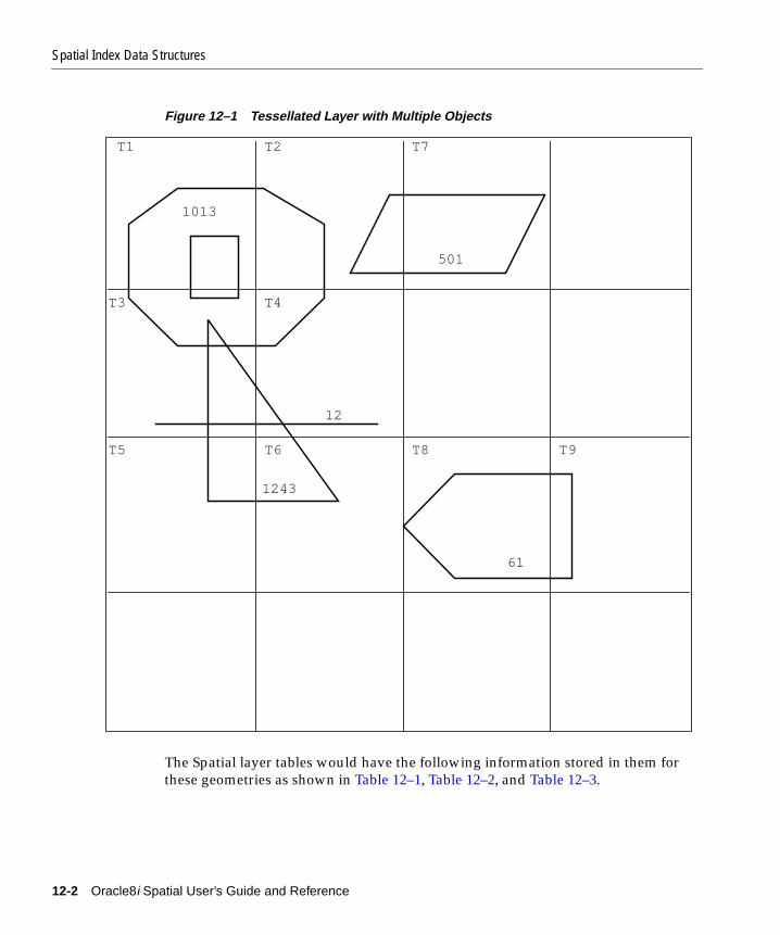
Spatial Index Data Structures
Figure 12–1 Tessellated Layer with Multiple Objects
The Spatial layer tables would have the following information stored in them forthese geometries as shown in Table 12–1, Table 12–2, and Table 12–3.
1243
1013
T1 T2 T7
T3 T4
T6T5
61
T8 T9
501
12
12-2 Oracle8i Spatial User’s Guide and Reference

Spatial Index Data Structures
Table 12–1 <layername>_SDOLAYER
Table 12–2 <layername>_SDOGEOM
SDO_ORDCNT(number)
SDO_LEVEL(number)
SDO_NUMTILES(number)
4 2 NULL
SDO_GID(number )
SDO_ESEQ(number )
SDO_ETYPE(number )
SDO_SEQ(number )
SDO_X1(number )
SDO_Y1(number )
SDO_X2(number )
SDO_Y2(number )
1013 0 3 0 P1(X) P1(Y) P2(X) P2(Y)
1013 0 3 1 P2(X) P2(Y) P3(X) P3(Y)
1013 0 3 2 P3(X) P3(Y) P4(X) P4(Y)
1013 0 3 3 P4(X) P4(Y) P5(X) P5(Y)
1013 0 3 4 P5(X) P5(Y) P6(X) P6(Y)
1013 0 3 5 P6(X) P6(Y) P7(X) P7(Y)
1013 0 3 6 P7(X) P7(Y) P8(X) P8(Y)
1013 0 3 7 P8(X) P8(Y) P1(X) P1(Y)
1013 1 3 0 G1(X) G1(Y) G2(X) G2(Y)
1013 1 3 1 G2(X) G2(Y) G3(X) G3(Y)
1013 1 3 2 G3(X) G3(Y) G4(X) G4(Y)
1013 1 3 3 G4(X) G4(Y) G1(X) G1(Y)
501 0 3 0 A1(X) A1(Y) A2(X) A2(Y)
501 0 3 1 A2(X) A2(Y) A3(X) A3(Y)
501 0 3 2 A3(X) A3(Y) A4(X) A4(Y)
501 0 3 3 A4(X) A4(Y) A1(X) A1(Y)
1243 0 3 0 B1(X) B1(Y) B2(X) B2(Y)
1243 0 3 1 B2(X) B2(Y) B3(X) B3(Y)
1243 0 3 2 B3(X) B3(Y) B1(X) B1(Y)
12 0 2 0 D1(X) D1(Y) D2(X) D2(Y)
61 0 3 0 C1(X) C1(Y) C2(X) C2(Y)
61 0 3 1 C2(X) C2(Y) C3(X) C3(Y)
61 0 3 2 C3(X) C3(Y) C4(X) C4(Y)
61 0 3 3 C4(X) C4(Y) C5(X) C5(Y)
61 0 3 4 C5(X) C5(Y) C1(X) C1(Y)
Querying Spatial Data 12-3

Spatial Query
Table 12–3 <layername>_SDOINDEX
12.3 Spatial QueryA typical spatial query is to request all objects that lie within a defined fence orwindow. A query window is shown in Figure 12–2 by the dotted-line box. Adynamic query window refers to a fence that is not defined in the database, butthat must be defined and indexed prior to using it.
SDO_GID(number)
SDO_CODE(raw)
1013 T1
1013 T2
1013 T3
1013 T4
501 T2
501 T7
1243 T3
1243 T4
1243 T5
1243 T6
12 T3
12 T4
61 T8
61 T9
12-4 Oracle8i Spatial User’s Guide and Reference
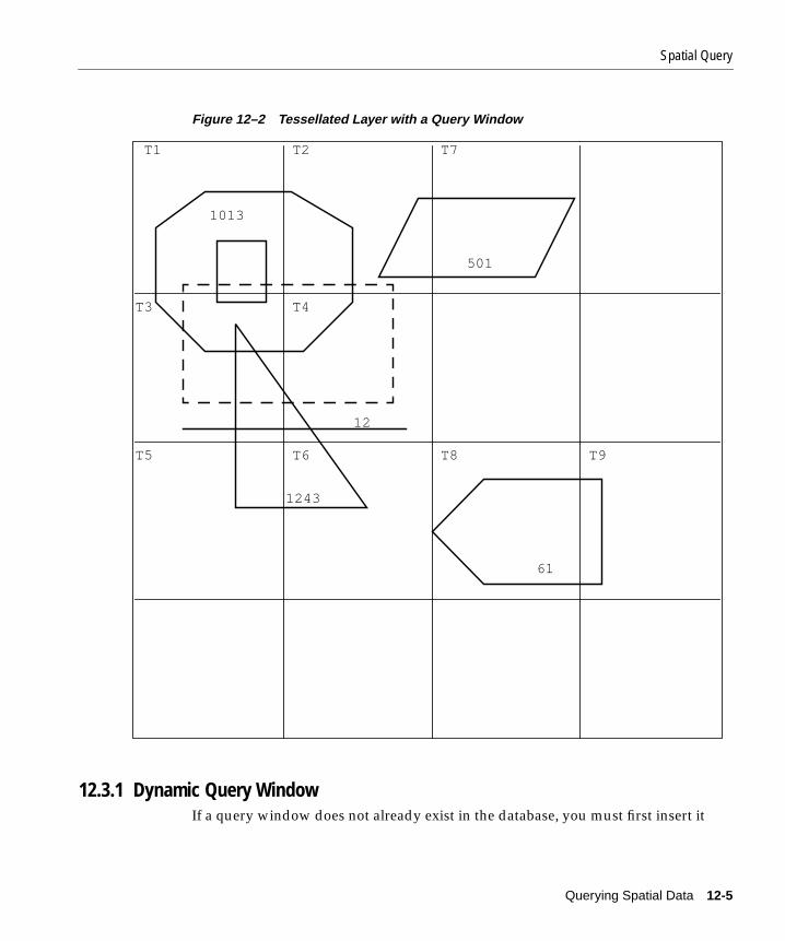
Spatial Query
Figure 12–2 Tessellated Layer with a Query Window
12.3.1 Dynamic Query WindowIf a query window does not already exist in the database, you must first insert it
1243
12
1013
T1 T2 T7
T3 T4
T6T5
61
T8 T9
501
Querying Spatial Data 12-5

Spatial Query
and create an index for it. Because not all Oracle users necessarily have insertprivileges, Spatial includes the SDO_WINDOW PL*SQL package. See Chapter 16,"Window Functions and Procedures", for more information.
The SDO_WINDOW package is not automatically installed when you installSpatial. This allows a DBA to control the schema under which this packageoperates. Choose an Oracle user who has insert privilege and compile the SDO_WINDOW package under that user. For example, you could choose the mdsysOracle user:
sqlplus mdsys/passwordSQL> @$ORACLE_HOME/md/admin/sdowin.sqlSQL> @$ORACLE_HOME/md/admin/prvtwin.plb
After compiling, the routines are available for use. When you call a routine in thispackage, and the routine performs an INSERT operation, the insert will occurunder the mdsys schema. Note that it is not a requirement to use the mdsysaccount. You can select any Oracle user with insert privileges.
If you need to perform other INSERT, UPDATE, or DELETE operations, and youcannot guarantee that the user of your application has those privileges, you canwrite your own PL*SQL package similar to the SDO_WINDOW package. You willhave to compile your package under a user with the required database privileges.
12.3.2 Primary Filter QueryTo resolve the window query shown in Figure 12–2, build a layer for the queryfence if it is not already defined:
SQL> EXECUTE MDSYS.SDO_WINDOW.CREATE_WINDOW_LAYER (fencelayer, DIMNUM1, LB1,UB1, TOLERANCE1, DIMNAME1, DIMNUM2, LB2, UB2, TOLERANCE2, DIMNAME2);
Next, insert the ordinates for the query fence into the layer tables:
SQL> EXECUTE DBMS_OUTPUT.PUTLINE(MDSYS.SDO_WINDOW.BUILD_WINDOW_FIXED(comp_user, fencelayer, SDO_ETYPE, TILE_SIZE, X1,Y1, X2,Y2, X3,Y3, X4,Y4, X1,Y1));
Query SDO_LEVEL from the <fencelayer>_SDOLAYER table to pass the correctTILE_SIZE to the SDO_WINDOW.BUILD_WINDOW_FIXED() procedure.
Now you can construct a query that joins the index of the query window to theappropriate layer index and determines all elements that have these tiles incommon. The following SQL query form is used:
SELECT DISTINCT A.SDO_GID
12-6 Oracle8i Spatial User’s Guide and Reference

Spatial Query
FROM <layer1>_SDOINDEX A, <fencelayer>_SDOINDEX BWHERE A.SDO_CODE = B.SDO_CODE AND B.SDO_GID = {GID returned from SDO_WINDOW.BUILD_WINDOW_FIXED};
The result set of this query is the primary filter set. In this case, the result set is:
{ 1013,501,1243,12 }
12.3.3 Secondary Filter QueryThe secondary filter performs exact geometry calculations of the tiles selected bythe primary filter. The following example shows the primary and secondary filters:
SELECT SDO_X1, SDO_Y1, SDO_X2, SDO_Y2, SDO_X3, SDO_Y3, SDO_X4, SDO_Y4FROM <layer1>_SDOGEOM,(SELECT SDO_GID GID1 FROM ( SELECT DISTINCT A.SDO_GID FROM <layer1>_SDOINDEX A, <fencelayer>_SDOINDEX B WHERE A.SDO_CODE = B.SDO_CODE AND B.SDO_GID = {GID returned from SDO_WINDOW.BUILD_WINDOW_FIXED}
) WHERE SDO_GEOM.RELATE(’<layer1>’, SDO_GID, ’ANYINTERACT’, ’<fence>’, 1) =’TRUE’ )WHERE SDO_GID = GID1;
This query would return all the geometry IDs that lie within or overlap thewindow. In this example, the results of the secondary filter would be:
{1243,1013}
The example in this section uses the SDO_GEOM.RELATE() secondary filter. Forbetter performance, use the overloaded version of this function which explicitlylists the coordinates of the query window whenever possible. See Chapter 15,"Geometry Functions and Procedures", for details on using this function.
Querying Spatial Data 12-7

Spatial Join
12.4 Spatial JoinA spatial join is the same as a regular join except that the predicate involves aspatial operator. In Spatial, a spatial join takes place between two layers;specifically, two <layername>_SDOINDEX tables are joined.
Spatial joins can be used to answer questions such as, “which highways crossnational parks?”
This query could be resolved by joining a layer that stores national park geometrieswith one that stores highway geometries. Figure 12–3 illustrates how the joinwould be accomplished for this example using the OGIS V1 schema model.
Figure 12–3 Spatial Join of Two Layers
The PRIMARY filter would identify pairs of park GIDs and highway GIDs thatcross in the index. The query that performs the primary filter join (assumingfixed-size tile indexing) is as follows:
SELECT DISTINCT A.SDO_GID,B.SDO_GID FROM PARKS_SDOINDEX A, HIGHWAYS_SDOINDEX B WHERE A.SDO_CODE = B.SDO_CODE
User
Defined
Attribute
Tables
Spatial
Data
PARKS_SDOINDEX:
CODE
Structures
PARKS:
PARKS_SDODIM:
PARKS_SDOGEOM:
GID
DIM LB UB
NAME GID CAMPSITE# ...
HIGHWAYS:
HIGHWAYS_SDODIM:
ESEQ ETYPE SEQ X1
HIGHWAYS_SDOGEOM:
HIGHWAYS_SDOINDEX:
GID
NAME GID WIDTH ...
MAX CODEGID MAX
Y1 GID ESEQ ETYPE SEQ X1 Y1
TOL NAME DIM LB UB TOL NAME
12-8 Oracle8i Spatial User’s Guide and Reference

Spatial Join
The result set of the primary filter must be passed through the secondary filter toget the exact set of parks/highways GID pairs that cross. The full query is shown inthe following example:
Suppose the original query had asked, “which 4-lane highways cross nationalparks?” You could modify the preceding SQL statement to join back to theHIGHWAYS table where HIGHWAYS.WIDTH=4. This combination of spatial andrelational attributes in a single query is one of the essential reasons for usingSpatial.
SELECT DISTINCT GID_B FROM ( SELECT /*+ index(a PARKS_SDOINDEX_SDO_CODE_INDEX) index(b HIGHWAYS_SDOINDEX_SDO_CODE_INDEX) use_nl(a b) no_merge */ DISTINCT A.SDO_GID GID_A, B.SDO_CODE GID_B FROM PARKS_SDOINDEX A, HIGHWAYS_SDOINDEX B WHERE A.SDO_CODE = B.SDO_CODE ) WHERE SDO_GEOM.RELATE ( ’PARKS’, GID_A, ’ANYINTERACT’, ’HIGHWAYS’, GID_B) <> ’FALSE’;
Primary
Secondary
Filter
Filter
Querying Spatial Data 12-9

Spatial Join
12-10 Oracle8i Spatial User’s Guide and Reference

Administrative Functions and Proce
13
Administrative Functions and ProceduresThe SDO_ADMIN procedures create and maintain spatial structures in thedatabase, and are used to perform the following tasks:
■ Tessellate entries in a geometry table and place them in a spatial index table
■ Verify spatial index information
This chapter contains descriptions of the administrative functions and proceduresused for working with spatially indexed geometric data. This chapter refers to therelational Spatial model only.
Table 13–1 lists the administrative functions and procedures for working withspatially indexed geometry-based data.
Table 13–1 Administrative Procedures for Spatially Indexed Data
Procedure or Function Description
SDO_ADMIN.POPULATE_INDEX Generates a spatial index for the geometry tableusing either a set number of tiles, or a fixed-size tile.
SDO_ADMIN.POPULATE_INDEX_FIXED Generate a spatial index using fixed-size tiles. This isa deprecated procedure.
SDO_ADMIN.POPULATE_INDEX_FIXED_POINTS
Generates a spatial index using fixed-size tiles for alayer composed solely of point data.
SDO_ADMIN.SDO_CODE_SIZE Determines the required sizes for SDO_CODE andSDO_MAXCODE.
SDO_ADMIN.SDO_VERSION Returns the release number of the installed versionof the Spatial option.
SDO_ADMIN.UPDATE_INDEX Updates the spatial index based on changes to thegeometry table.
dures 13-1

SDO_ADMIN.UPDATE_INDEX_FIXED Updates a spatial index with fixed-size tiles. This isa deprecated procedure.
SDO_ADMIN.VERIFY_LAYER Checks for the existence of geometry and spatialindex tables.
Table 13–1 Administrative Procedures for Spatially Indexed Data (Cont.)
Procedure or Function Description
13-2 Oracle8i Spatial User’s Guide and Reference
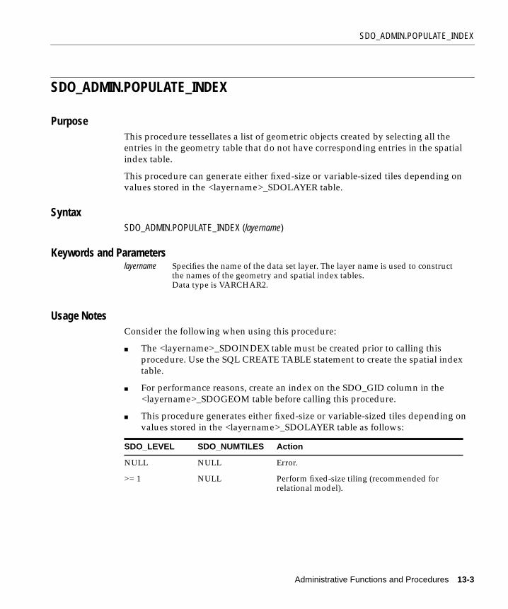
SDO_ADMIN.POPULATE_INDEX
SDO_ADMIN.POPULATE_INDEX
PurposeThis procedure tessellates a list of geometric objects created by selecting all theentries in the geometry table that do not have corresponding entries in the spatialindex table.
This procedure can generate either fixed-size or variable-sized tiles depending onvalues stored in the <layername>_SDOLAYER table.
SyntaxSDO_ADMIN.POPULATE_INDEX (layername)
Keywords and Parameters
Usage NotesConsider the following when using this procedure:
■ The <layername>_SDOINDEX table must be created prior to calling thisprocedure. Use the SQL CREATE TABLE statement to create the spatial indextable.
■ For performance reasons, create an index on the SDO_GID column in the<layername>_SDOGEOM table before calling this procedure.
■ This procedure generates either fixed-size or variable-sized tiles depending onvalues stored in the <layername>_SDOLAYER table as follows:
layername Specifies the name of the data set layer. The layer name is used to constructthe names of the geometry and spatial index tables.Data type is VARCHAR2.
SDO_LEVEL SDO_NUMTILES Action
NULL NULL Error.
>= 1 NULL Perform fixed-size tiling (recommended forrelational model).
Administrative Functions and Procedures 13-3

SDO_ADMIN.POPULATE_INDEX
■ If the <layername>_SDOINDEX table is empty, the procedure selects all thegeometries in the geometry table and generates index entries for them. If theindex table is not empty, the procedure determines which entries in thegeometry table do not have index entries, and generates them.
■ SDO_ADMIN.POPULATE_INDEX() behaves similarly to the CREATE INDEXstatement in SQL. An implicit commit is executed after the procedure is called.
■ SDO_ADMIN.POPULATE_INDEX() operates as a single transaction. To reducethe amount of rollback required to execute this procedure, you can write aroutine that loops and calls SDO_ADMIN.UPDATE_INDEX() repeatedly. SeeSection A.3.1, "cr_spatial_index.sql Script" for more information.
Example 13–1 tessellates all the geometric objects in the LAYER1_SDOGEOM tableand adds the generated tiles to the LAYER1_SDOINDEX table.
Example 13–1 Populate an Index
SQL> EXECUTE SDO_ADMIN.POPULATE_INDEX(’layer1’);SQL> COMMIT;
Related Topics■ SDO_ADMIN.UPDATE_INDEX( ) procedure
>= 1 >= 1 Perform hybrid indexing. The SDO_LEVELcolumn defines the partition bucket size. TheSDO_NUMTILES column defines the numberof tiles to generate per geometry.
Note: hybrid indexing is for experimentationpurposes only in the relational model..
NULL >= 1 Not supported.
SDO_LEVEL SDO_NUMTILES Action
13-4 Oracle8i Spatial User’s Guide and Reference
SDO_ADMIN.POPULATE_INDEX_FIXED
SDO_ADMIN.POPULATE_INDEX_FIXED
PurposeThis procedure is provided for compatibility with Spatial Cartridge release 8.0.3tables, but it has been replaced by enhanced features in the SDO_ADMIN.POPULATE_INDEX() procedure, in order to support schema changes asshown in Section 10.1.
This procedure tessellates a list of geometric objects created by selecting all theentries in the geometry table that do not have corresponding entries in the spatialindex table. This procedure can also tessellate all the geometric objects in ageometry table or view and add the tiles to the spatial index table.
Use this procedure to tessellate the geometries into fixed-size tiles.
SyntaxSDO_ADMIN.POPULATE_INDEX_FIXED (layername, tile_size, [synch_flag,] [sdo_tile_flag,] [sdo_maxcode_flag])
Keywords and Parameters
layername Specifies the name of the data set layer. The layer name is used to constructthe name of the geometry and spatial index tables.Data type is VARCHAR2.
tile_size Specifies the number of tessellations required to achieve the desired tile size(see the Usage Notes).Data type is INTEGER.
synch_flag Specifies whether to tessellate every geometric object in the geometry table,or only those that do not have corresponding entries in the spatial indextable. If TRUE, only those geometric objects in the geometry table that do nothave any corresponding tiles in the spatial index table are tessellated. IfFALSE, all the geometric objects in the geometry table are tessellated andnew tiles are simply added to the spatial index table.Default value is TRUE.Data type is BOOLEAN.
sdo_tile_flag For internal use only. Not supported in this release.Default value is FALSE.
Administrative Functions and Procedures 13-5
SDO_ADMIN.POPULATE_INDEX_FIXED
Usage Notes
Consider the following when using this procedure:
■ The SQL CREATE TABLE statement is used to create the spatial index table,<layername>_SDOINDEX, prior to calling this procedure.
■ The layer is tessellated into equal-sized tiles based on the number passed in thetile_size parameter. The value of tile_size specifies how many times totessellate the layer. See Section 11.3.2, "Spatial Indexing with Fixed-Size Tiles".
■ For performance reasons, set the synch_flag to FALSE when the spatial indextable contains zero rows.
■ For performance reasons, create an index on the SDO_GID column in the<layername>_SDOGEOM table before calling this procedure.
■ SDO_ADMIN.POPULATE_INDEX_FIXED() behaves similarly to the CREATEINDEX statement in SQL. An implicit commit is executed after the procedure iscalled.
■ SDO_ADMIN.POPULATE_INDEX_FIXED() operates as a single transaction. Toreduce the amount of rollback required to execute this procedure, you canwrite a routine that loops and calls SDO_ADMIN.UPDATE_INDEX_FIXED()repeatedly. See Section A.3.1, "cr_spatial_index.sql Script" for more information.
Example 13–2 tessellates all the geometric objects in the LAYER1_SDOGEOM tableusing fixed-size tiles, and adds the generated tiles to the LAYER1_SDOINDEX table.
sdo_maxcode_flag
Specifies whether or not the SDO_MAXCODE column is populated. If TRUE,SDO_MAXCODE is populated. If FALSE, the column is not populated. Setthis flag to FALSE for the recommended fixed-size tiling.Default value is TRUE.Data type is BOOLEAN.
Note: This procedure is likely to be removed in a future release ofSpatial.
13-6 Oracle8i Spatial User’s Guide and Reference

SDO_ADMIN.POPULATE_INDEX_FIXED
Example 13–2 Populate an Index with Fixed-Size Tiles
SQL> EXECUTE SDO_ADMIN.POPULATE_INDEX_FIXED(’layer1’,4,FALSE,FALSE,FALSE);
Related Topics■ SDO_ADMIN.UPDATE_INDEX_FIXED( ) procedure
■ SDO_TUNE.ESTIMATE_TILING_LEVEL( ) function
Administrative Functions and Procedures 13-7
SDO_ADMIN.POPULATE_INDEX_FIXED_POINTS
SDO_ADMIN.POPULATE_INDEX_FIXED_POINTS
PurposeThis procedure builds an index with fixed-size tiles for a geometry layer consistingsolely of point data. Because a point is indexed using a single tile, specialoptimizations are possible.
SyntaxSDO_ADMIN.POPULATE_INDEX_FIXED_POINTS (layername, sdo_tile_flag, commit_count)
Keywords and Parameters
Usage NotesConsider the following when using this procedure:
■ The <layername>_SDOLAYER, <layername>_SDOGEOM, and <layername>_SDODIM tables must be populated prior to calling this procedure.
■ The <layername>_SDOINDEX table must be created prior to calling thisprocedure. Use the SQL CREATE TABLE statement to create the spatial indextable.
■ For performance reasons, create an index on the SDO_GID column in the<layername>_SDOGEOM table before calling this procedure.
■ If the <layername>_SDOINDEX table is empty, the procedure selects all thegeometries in the geometry table and generates index entries for them. If theindex table is not empty, the procedure determines which entries in thegeometry table do not have index entries, and generates them.
layername Specifies the name of the data set layer.Data type is VARCHAR2.
sdo_tile_flag Specifies whether or not to generate the SDO_TILE column.Default value is FALSE.Data type is BOOLEAN.
commit_count Specifies how many points to index before updating and committing thedata.Default value is 50.Data type is NUMBER.
13-8 Oracle8i Spatial User’s Guide and Reference

SDO_ADMIN.POPULATE_INDEX_FIXED_POINTS
Example 13–3 tessellates all the points in the LAYER1_SDOGEOM table and addsthe generated tiles to the LAYER1_SDOINDEX table. This example commits afterevery 100 points.
Example 13–3 Populate an Index with Fixed-Size Tiles Based on Point Data
SQL> EXECUTE SDO_ADMIN.POPULATE_INDEX_FIXED_POINTS(’layer1’, FALSE, 100 );
Related Topics■ SDO_ADMIN.UPDATE_INDEX( ) procedure
Administrative Functions and Procedures 13-9

SDO_ADMIN.SDO_CODE_SIZE
SDO_ADMIN.SDO_CODE_SIZE
PurposeThis function determines the size that the SDO_MAXCODE column should be inthe <layername>_SDOINDEX table.
SyntaxSDO_ADMIN.SDO_CODE_SIZE (layername)
Keywords and Parameters
ReturnsThis function returns the required size in bytes for the SDO_MAXCODE column.Data type is INTEGER.
Usage NotesThe SDO_CODE column is used to store the bit-interleaved cell ID of a tile thatcovers a geometry. The SDO_MAXCODE column is SDO_CODE padded out oneplace farther than the longest allowable code name for the index. Both columns aredefined as RAW data types, with a maximum of 255 bytes. Use the SDO_ADMIN.SDO_CODE_SIZE() function to fine-tune the size of the column.
Always declare the SDO_CODE column to raw(255).
Related TopicsNone.
layername Specifies the name of the data set layer.Data type is VARCHAR2.
13-10 Oracle8i Spatial User’s Guide and Reference

SDO_ADMIN.SDO_VERSION
SDO_ADMIN.SDO_VERSION
PurposeThis function returns the current installed version of Spatial.
SyntaxSDO_ADMIN.SDO_VERSION
Keywords and ParametersNone.
ReturnsThis function returns a string describing the version of Spatial installed on the localsystem.Data type is VARCHAR2.
Usage NotesThe following version strings can be returned by this procedure:
8.0.5.0.08.1.0.0.08.1.3.0.08.1.5.0.0
This information is useful in when migrating data between systems, or whenupgrading. See Appendix B for more information about migration.
Related TopicsNone.
Administrative Functions and Procedures 13-11

SDO_ADMIN.UPDATE_INDEX
SDO_ADMIN.UPDATE_INDEX
PurposeThis procedure tessellates a single geometric object in a geometry table or view andadds the tiles to the spatial index table. If the object already exists and has indexentries, those entries are deleted and replaced by the newly generated tiles.
SyntaxSDO_ADMIN.UPDATE_INDEX (layername, GID)
Keywords and Parameters
Usage NotesConsidert the following when using this procedure:
■ The <layername>_SDOINDEX table must exist prior to calling this procedure.Use the SQL CREATE TABLE statement to create the spatial index table.
■ For performance reasons, create an index on the SDO_GID column in the<layername>_SDOGEOM table before calling this procedure.
■ The values of the SDO_LEVEL and SDO_NUMTILES columns must be set inthe <layername>_SDOLAYER table before calling this procedure. Thisprocedure generates either fixed-size or hybrid tiles depending on valuesstored in the <layername>_SDOLAYER table as follows:
layername Specifies the name of the data set layer. The layer name is used toconstruct the name of the geometry table.Data type is VARCHAR2.
GID Specifies the geometric object identifier.Data type is NUMBER.
SDO_LEVEL SDO_NUMTILES Action
NULL NULL Error.
>= 1 NULL Perform indexing with fixed-size tiles(recommended for the relational model).
13-12 Oracle8i Spatial User’s Guide and Reference

SDO_ADMIN.UPDATE_INDEX
■ SDO_ADMIN.UPDATE_INDEX() does not perform an implicit commit after itexecutes and therefore the transaction can be rolled back.
Example 13–4 tessellates the polygon for geometry 25 and adds the generated tilesto the LAYER1_SDOINDEX table.
Example 13–4 Update an Index
SQL> EXECUTE SDO_ADMIN.UPDATE_INDEX(’layer1’, 25);SQL> COMMIT;
Related Topics■ SDO_ADMIN.POPULATE_INDEX( ) procedure
>= 1 >= 1 Perform hybrid indexing. The SDO_LEVELcolumn defines the partition bucket size. TheSDO_NUMTILES column defines the numberof tiles to generate per geometry.Note: hybrid indexing is for experimentationpurposes only in the relational model.
NULL >= 1 Not supported.
SDO_LEVEL SDO_NUMTILES Action
Administrative Functions and Procedures 13-13

SDO_ADMIN.UPDATE_INDEX_FIXED
SDO_ADMIN.UPDATE_INDEX_FIXED
PurposeThis procedure is provided for compatibility with Spatial Cartridge release 8.0.3tables, but it has been replaced by enhanced features in the SDO_ADMIN.UPDATE_INDEX() procedure to support schema changes as shown in Section 10.1.
This procedure tessellates a single geometric object in a geometry table or view andadds the fixed-sized tiles to the spatial index table. By default, these tiles willreplace existing ones for the same geometry; or optionally, existing tiles can be leftalone.
SyntaxSDO_ADMIN.UPDATE_INDEX_FIXED (layername, GID, tile_size, [replace_flag,] [sdo_tile_flag] [sdo_maxcode_flag])
Keywords and Parameters
layername Specifies the name of the data set layer. The layer name is used toconstruct the name of the geometry table.Data type is VARCHAR2.
GID Specifies the geometric object identifier.Data type is NUMBER.
tile_size Specifies the number of tessellations required to achieve the desiredfixed-size tiles. Each tessellation subdivides the tiles from theprevious level into four smaller tiles.Data type is INTEGER.
replace_flag Specifies whether or not to delete tiles for the GID before adding newones. If TRUE, tiles are deleted prior to inserting new entries into thespatial index table. If FALSE, new tiles are simply added to the spatialindex table.Default value is TRUE.Data type is BOOLEAN.
sdo_tile_flag For internal use only. Not supported in this release.Default value is FALSE.Data type is BOOLEAN.
13-14 Oracle8i Spatial User’s Guide and Reference

SDO_ADMIN.UPDATE_INDEX_FIXED
Usage Notes
Consider the following when using this procedure:
■ For performance reasons, set the replace_flag to FALSE when the spatial indextable contains no entries for the specified GID.
■ For performance reasons, create an index on the SDO_GID column in the<layername>_SDOGEOM table before calling this procedure.
■ SDO_ADMIN.UPDATE_INDEX_FIXED() does not perform an implicit commitafter it executes and therefore this transaction can be rolled back.
Example 13–5 tessellates the polygon for geometry 25 and adds the generated tilesto the LAYER1_SDOINDEX table.
Example 13–5 Update an Index with Fixed-Size Tiles
SQL> EXECUTE SDO_ADMIN.UPDATE_INDEX_FIXED (’layer1’,25,4,FALSE,FALSE,FALSE);
Related Topics■ SDO_ADMIN.POPULATE_INDEX_FIXED( ) procedure
■ SDO_TUNE.ESTIMATE_TILING_LEVEL( ) function
sdo_maxcode_flag Specifies whether or not the SDO_MAXCODE column is populated. IfTRUE, SDO_MAXCODE is populated. If FALSE, the column is notpopulated. Set this flag to FALSE for the recommended indexing withfixed-size tiles.Default value is TRUE.Data type is BOOLEAN.
Note: This procedure is likely to be removed in a future release ofSpatial.
Administrative Functions and Procedures 13-15

SDO_ADMIN.VERIFY_LAYER
SDO_ADMIN.VERIFY_LAYER
PurposeThis procedure checks for the existence of the geometry and spatial index tables.
SyntaxSDO_ADMIN.VERIFY_LAYER (layername,[maxtiles])
Keywords and Parameters
Usage NotesIf this procedure does not find the geometry and spatial index tables, it generatesthe following error: SDO 13113 (Oracle table does not exist.)
Example 13–6 verifies the LAYER1 data set layer.
Example 13–6 Verify a Layer
SQL> EXECUTE SDO_ADMIN.VERIFY_LAYER(’layer1’);
Related TopicsNone.
layername Specifies the name of the data set layer. The layer name is used toconstruct the name of the geometry and spatial index tables.Data type is VARCHAR2.
maxtiles For internal use only. Not supported in this release.
13-16 Oracle8i Spatial User’s Guide and Reference

Tuning Functions and Proce
14
Tuning Functions and ProceduresThis chapter contains descriptions of the tuning functions and procedures shown inTable 14–1. This chapter refers to the relational Spatial model only.
Table 14–1 Tuning Functions and Procedures
Function/Procedure Description
SDO_TUNE.AVERAGE_MBR Calculates the average minimum boundingrectangle for geometries in a layer.
SDO_TUNE.ESTIMATE_INDEX_PERFORMANCE
Estimates the spatial index selectivity.
SDO_TUNE.ESTIMATE_TILING_LEVEL Determines an appropriate tiling level forcreating fixed-size index tiles.
SDO_TUNE.ESTIMATE_TILING_TIME Estimates the tiling time for a layer, in seconds.
SDO_TUNE.EXTENT_OF Determines the minimum bounding rectangleof the data in a layer.
SDO_TUNE.HISTOGRAM_ANALYSIS Calculates statistical histograms for a spatiallayer.
SDO_TUNE.MIX_INFO Calculates geometry type information for aspatial layer, such as the percentage of eachgeometry type.
dures 14-1
SDO_TUNE.AVERAGE_MBR
SDO_TUNE.AVERAGE_MBR
PurposeThis function calculates the average minimum bounding rectangle (MBR) for allgeometries in a layer.
SyntaxSDO_TUNE.AVERAGE_MBR (layername, width, height)
Keywords and Parameters
ReturnsThe function returns the width and height of the average MBR for all geometries ina layer.
Data types for height and width are NUMBER.
Usage NotesThis function calculates the average MBR by keeping track of the maximum andminimum X and Y values for all geometries in a layer.
layername Specifies the name of the data set layer toexamine.Data type is VARCHAR2.
width Returns the width of the average MBR.Data type is OUT NUMBER.
height Returns the height of the average MBR.Data type is OUT NUMBER.
14-2 Oracle8i Spatial User’s Guide and Reference

SDO_TUNE.ESTIMATE_INDEX_PERFORMANCE
SDO_TUNE.ESTIMATE_INDEX_PERFORMANCE
PurposeThis function estimates the spatial index performance such as query selectivity andwindow query time for a layer.
SyntaxSDO_TUNE.ESTIMATE_INDEX_PERFORMANCE (layername, sample_ratio, tiling_level, num_tiles, window_layer, window_gid, tiling_time, filter_time, query_time)
Keywords and Parameters
ReturnsThe function returns a number between 0.0 and 1.0 representing estimated spatialindex selectivity. Data type is NUMBER.
layername Specifies the name of the data set layer to examine.Data type is VARCHAR2.
sample_ratio Specifies the size ratio between the original layer and the samplelayer to be generated.Data type is INTEGER.Default is 20.
tiling_level Specifies the spatial index level at which the layer is to be tessellated.Data type is INTEGER.
num_tiles Specifies the number of tiles for variable or hybrid tessellation.Data type is INTEGER.
window_layer Specifies the name of the spatial layer in which the window geometryis stored.Data type is VARCHAR2.
window_gid Specifies the window geometry ID.Data type is NUMBER.
tiling_time Returns the estimated tiling time in seconds.Data type is OUT NUMBER
filter_time Returns the estimated spatial index filter time in seconds.Data type is OUT NUMBER
query_time Returns the estimated window query time in seconds.Data type is OUT NUMBER.
Tuning Functions and Procedures 14-3

SDO_TUNE.ESTIMATE_INDEX_PERFORMANCE
The function also returns the estimated tiling time, filter time, and query time. Datatype for these variables is NUMBER.
Usage Notes■ A larger selectivity number indicates better selectivity. A selectivity of 0.0
indicates an error.
■ A larger sample_ratio means faster but less accurate estimation.
14-4 Oracle8i Spatial User’s Guide and Reference
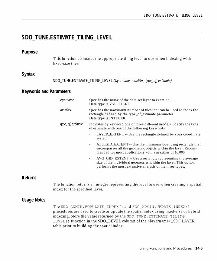
SDO_TUNE.ESTIMATE_TILING_LEVEL
SDO_TUNE.ESTIMATE_TILING_LEVEL
PurposeThis function estimates the appropriate tiling level to use when indexing withfixed-size tiles.
SyntaxSDO_TUNE.ESTIMATE_TILING_LEVEL (layername, maxtiles, type_of_estimate)
Keywords and Parameters
ReturnsThe function returns an integer representing the level to use when creating a spatialindex for the specified layer.
Usage NotesThe SDO_ADMIN.POPULATE_INDEX() and SDO_ADMIN.UPDATE_INDEX()procedures are used to create or update the spatial index using fixed-size or hybridindexing. Store the value returned by the SDO_TUNE.ESTIMATE_TILING_LEVEL() function in the SDO_LEVEL column of the <layername>_SDOLAYERtable prior to building the spatial index.
layername Specifies the name of the data set layer to examine.Data type is VARCHAR2.
maxtiles Specifies the maximum number of tiles that can be used to index therectangle defined by the type_of_estimate parameter.Data type is INTEGER.
type_of_estimate Indicates by keyword one of three different models. Specify the typeof estimate with one of the following keywords:
• LAYER_EXTENT -- Use the rectangle defined by your coordinatesystem.
• ALL_GID_EXTENT -- Use the minimum bounding rectangle thatencompasses all the geometric objects within the layer. Recom-mended for most applications with a maxtiles of 10,000.
• AVG_GID_EXTENT -- Use a rectangle representing the averagesize of the individual geometries within the layer. This optionperforms the most extensive analysis of the three types.
Tuning Functions and Procedures 14-5
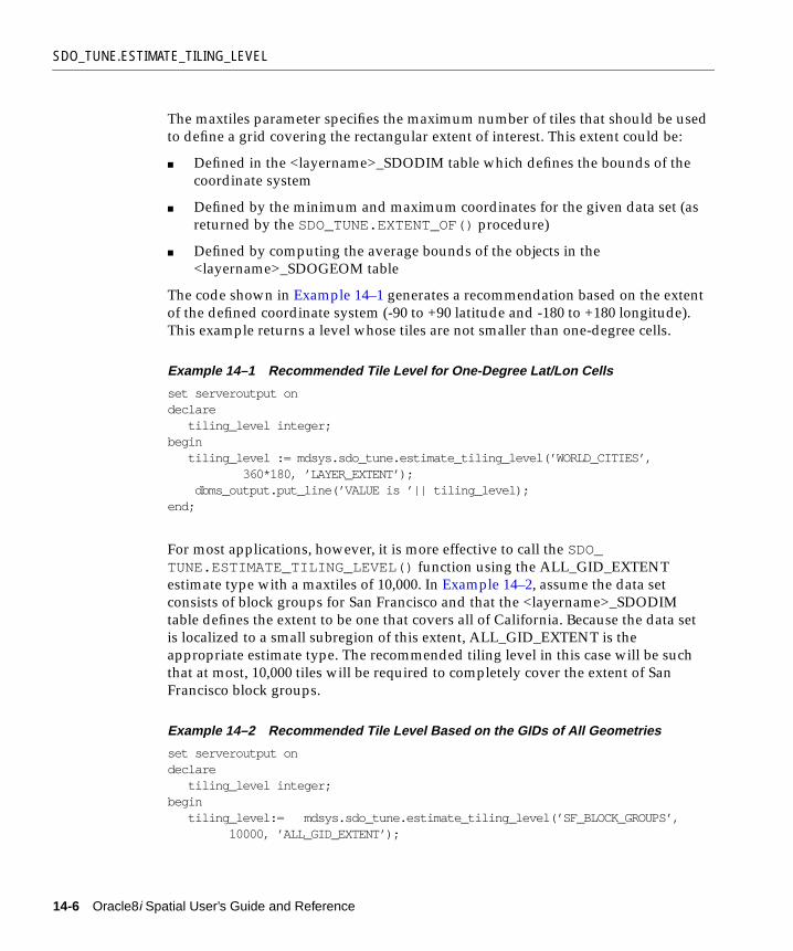
SDO_TUNE.ESTIMATE_TILING_LEVEL
The maxtiles parameter specifies the maximum number of tiles that should be usedto define a grid covering the rectangular extent of interest. This extent could be:
■ Defined in the <layername>_SDODIM table which defines the bounds of thecoordinate system
■ Defined by the minimum and maximum coordinates for the given data set (asreturned by the SDO_TUNE.EXTENT_OF() procedure)
■ Defined by computing the average bounds of the objects in the<layername>_SDOGEOM table
The code shown in Example 14–1 generates a recommendation based on the extentof the defined coordinate system (-90 to +90 latitude and -180 to +180 longitude).This example returns a level whose tiles are not smaller than one-degree cells.
Example 14–1 Recommended Tile Level for One-Degree Lat/Lon Cells
set serveroutput ondeclare tiling_level integer;begin tiling_level := mdsys.sdo_tune.estimate_tiling_level(’WORLD_CITIES’, 360*180, ’LAYER_EXTENT’); dbms_output.put_line(’VALUE is ’|| tiling_level);end;
For most applications, however, it is more effective to call the SDO_TUNE.ESTIMATE_TILING_LEVEL() function using the ALL_GID_EXTENTestimate type with a maxtiles of 10,000. In Example 14–2, assume the data setconsists of block groups for San Francisco and that the <layername>_SDODIMtable defines the extent to be one that covers all of California. Because the data setis localized to a small subregion of this extent, ALL_GID_EXTENT is theappropriate estimate type. The recommended tiling level in this case will be suchthat at most, 10,000 tiles will be required to completely cover the extent of SanFrancisco block groups.
Example 14–2 Recommended Tile Level Based on the GIDs of All Geometries
set serveroutput ondeclare tiling_level integer;begin tiling_level:= mdsys.sdo_tune.estimate_tiling_level(’SF_BLOCK_GROUPS’, 10000, ’ALL_GID_EXTENT’);
14-6 Oracle8i Spatial User’s Guide and Reference

SDO_TUNE.ESTIMATE_TILING_LEVEL
dbms_output.put_line(’VALUE is’ ,|| tiling_level);end;
The third type of estimate helps determine the tiling level that should be used suchthat on average, the maxtiles parameter defines the number of tiles to cover theextent of a single geometry in the layer. This estimate type requires the mostcomputation of the three because the bounding rectangle of every geometry is usedin calculating the average extent. In Example 14–3, eight tiles on average are usedto cover any block group in San Francisco.
Example 14–3 Recommended Tile Level Based on Average Extent of All Geometries
set serveroutput ondeclare tiling_level integer;begin tiling_level := mdsys.sdo_tune.estimate_tiling_level(’SF_BLOCK_GROUPS’, 8, ’AVG_GID_EXTENT’); dbms_output.put_line(’Tiling level value is ’ || tiling_level);end;
Related Topics■ SDO_ADMIN.POPULATE_INDEX
■ SDO_ADMIN.UPDATE_INDEX
■ SDO_TUNE.EXTENT_OF
■ Section A.2.2, "Understanding the Tiling Level"
■ Section A.2.4, "Visualizing the Spatial Index (Drawing Tiles)"
Tuning Functions and Procedures 14-7

SDO_TUNE.ESTIMATE_TILING_TIME
SDO_TUNE.ESTIMATE_TILING_TIME
PurposeThis function returns the estimated time to tessellate a layer.
SyntaxSDO_TUNE.ESTIMATE_TILING_TIME (layername, sample_ratio, tiling_level, num_tiles)
Keywords and Parameters
ReturnsThis function returns the estimated tiling time in seconds. A return of 0 indicates anerror.
Data type is NUMBER.
Usage NotesNone.
layername Specifies the name of the data set layer toexamine.Data type is VARCHAR2.
sample_ratio Specifies the size ratio between the original layerand the sample layer to be generated.Data type is INTEGER.Default is 20.
tiling_level Specifies the spatial index level at which the layeris to be tessellated.Data type is INTEGER.
num_tiles Specifies the number of tiles for variable orhybrid tessellation.Data type is INTEGER.
14-8 Oracle8i Spatial User’s Guide and Reference

SDO_TUNE.EXTENT_OF
SDO_TUNE.EXTENT_OF
PurposeThis function determines the extent of all geometries in a layer.
SyntaxSDO_TUNE.EXTENT_OF (layername, min_X, max_X, min_Y, max_Y)
Keywords and Parameters
ReturnsThis function returns the coordinates of the minimum bounding rectangle for allgeometric data in a layer. The data type is NUMBER for the four return values.
Usage NotesNone.
Related Topics■ SDO_TUNE.ESTIMATE_TILING_LEVEL() function
layername Specifies the name of the data set layer. The layername is used to construct the name of thegeometry and spatial index tables.Data type is VARCHAR2.
min_X Minimum X value of the bounding rectangle.Data type is NUMBER.
max_X Maximum X value of the bounding rectangle.Data type is NUMBER.
min_Y Minimum Y value of the bounding rectangle.Data type is NUMBER.
max_Y Maximum Y value of the bounding rectangle.Data type is NUMBER.
Tuning Functions and Procedures 14-9

SDO_TUNE.HISTOGRAM_ANALYSIS
SDO_TUNE.HISTOGRAM_ANALYSIS
PurposeThis procedure generates statistical histograms based on a layer.
SyntaxSDO_TUNE.HISTOGRAM_ANALYSIS (layername, result_table, type_of_histogram, max_value, intervals)
Keywords and Parameters
ReturnsThe procedure populates the result table with statistical histograms for a spatiallayer.
Usage Notes■ You must create the result table prior to calling this procedure. The table has
the following format:
CREATE TABLE histogram (value NUMBER, count NUMBER);
layername Specifies the name of the spatial data set layer to examine.Data type is VARCHAR2.
result_table Specifies the name of the result table where the histogram willbe stored.Data type is VARCHAR2.
type_of_histogram Specifies one of three types of histograms:
• TILES_VS_LEVEL (default)
• GEOMS_VS_AREA
• GEOMS_VS_VERTICES
Data type is VARCHAR2.
max_value Specifies the upper limit of the histogram.Data type is NUMBER.
intervals Specifies the number of intervals between 0 and max_value.Data type is INTEGER.
14-10 Oracle8i Spatial User’s Guide and Reference

SDO_TUNE.HISTOGRAM_ANALYSIS
■ The following types of histograms are available:
TILES_VS_LEVEL Provides the number of tiles at different spatial indexlevels. This histogram is used to evaluate the spatialindex that is already built on the layer.
GEOMS_VS_AREA Provides the number of geometries in different sizeranges. The shape of this histogram could be helpful inchoosing a proper index type and index level.
GEOMS_VS_VERTICES Provides a histogram of the geometry count against thenumber of vertices. This histogram could helpdetermine if spatial index selectivity is important for thelayer. Because the number of vertices determines theperformance of the secondary filter, selectivity of theprimary filter could be crucial for layers that containmany complicated geometries.
Tuning Functions and Procedures 14-11

SDO_TUNE.MIX_INFO
SDO_TUNE.MIX_INFO
PurposeThis function provides the number of geometries of each type stored in the layer.
SyntaxSDO_TUNE.MIX_INFO (layername)
Keywords and Parameters
ReturnsThis function calculates geometry type information for the layer. It returns thenumber of geometries of different type, as well as the percentages of points, linestrings, polygons, and complex geometries.
Usage NotesNone.
layername Specifies the name of the spatial data set layer toexamine.Data type is VARCHAR2.
14-12 Oracle8i Spatial User’s Guide and Reference
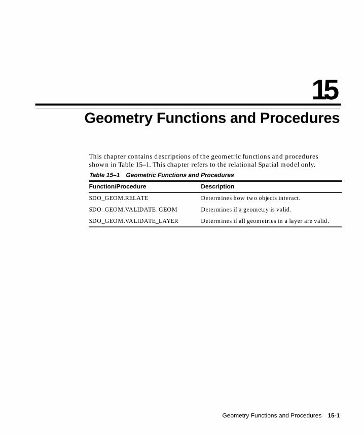
Geometry Functions and Proce
15
Geometry Functions and ProceduresThis chapter contains descriptions of the geometric functions and proceduresshown in Table 15–1. This chapter refers to the relational Spatial model only.
Table 15–1 Geometric Functions and Procedures
Function/Procedure Description
SDO_GEOM.RELATE Determines how two objects interact.
SDO_GEOM.VALIDATE_GEOM Determines if a geometry is valid.
SDO_GEOM.VALIDATE_LAYER Determines if all geometries in a layer are valid.
dures 15-1

SDO_GEOM.RELATE
SDO_GEOM.RELATE
PurposeThis function examines two geometry objects to determine their spatialrelationship. It is available in two forms. See the Usage Notes for more information.
SyntaxSDO_GEOM.RELATE (layername1, SDO_GID1, mask, [layername2,] SDO_GID2)
SDO_GEOM.RELATE (layername1, SDO_GID1, mask, X_tolerance, Y_tolerance, SDO_ETYPE, num_ordinates, X_ordinate1, Y_ordinate1 [,...,Xn, Yn] [,SDO_ETYPE, num_ordinates, X_ordinate1, Y_ordinate1 [,...,Xn, Yn]])
Keywords and Parameters
layername1,layername2
Specifies the name of the data set layer. The layer name is used toconstruct the name of the geometry and spatial index tables.Data type is VARCHAR2.
SDO_GID1,SDO_GID2
Specifies the geometry object identifier.Data type is NUMBER.
mask Specifies a list of relationships to check. See the list of keywords in theUsage Notes.
X_tolerance,
Y_tolerance
Specifies the distance two points can be apart and still be consideredthe same due to rounding errors. Tolerance must be greater than zero.If you want zero tolerance, enter a number such as 0.000005, wherethe number of zeros to the right of the decimal point matches theprecision of your data.Data type is NUMBER.
SDO_ETYPE Specifies the type of geometry element.Data type is INTEGER, corresponding to the following constants:
1 SDO_GEOM.POINT_TYPE
2 SDO_GEOM.LINESTRING_TYPE
3 SDO_GEOM.POLYGON_TYPE
15-2 Oracle8i Spatial User’s Guide and Reference

SDO_GEOM.RELATE
ReturnsThe SDO_GEOM.RELATE() function can return three types of answers:
1. If you pass a mask listing one or more relationships, the function returns thename of the relationship if it is true for the pair of geometries. If all of therelationships are false, the function returns FALSE.
2. If you pass the DETERMINE keyword in the mask, the function returns the onerelationship keyword that best matches the geometries. DETERMINE can onlybe used when SDO_GEOM.RELATE() is in the SELECT clause of the SQLstatement.
3. If you pass the ANYINTERACT keyword in the mask, the function returnsTRUE if the two geometries are not disjoint.
The data type is VARCHAR2.
Usage NotesUse the first form of the function to examine two stored geometric objects.
Use the second form of the function to compare a stored object against auser-defined object. You can specify up to 123 vertices for a single-elementgeometry. If the geometry has multiple elements, the total number of argumentspassed, including SDO_ETYPE, num_ordinates, and the list of vertex coordinates,cannot exceed 255 values.
The following relationships can be tested:
■ ANYINTERACT - Returns TRUE if the objects are not disjoint.
■ CONTAINS - Returns CONTAINS if the second object is entirely within thefirst object and the object boundaries do not touch; otherwise, returnsFALSE.
■ COVEREDBY - Returns COVEREDBY if the first object is entirely withinthe second object and the object boundaries touch at one or more points;otherwise, returns FALSE.
num_ordinates Specifies the number of ordinates for this element. Data type isNUMBER.
X_ordinateN,
Y_ordinateN
Specifies the X and Y values of a vertex (coordinate pair) in ageometry.Data type is NUMBER.
Geometry Functions and Procedures 15-3

SDO_GEOM.RELATE
■ COVERS - Returns COVERS if the second object is entirely within the firstobject and the boundaries touch in one or more places; otherwise, returnsFALSE.
■ DISJOINT - Returns DISJOINT if the objects have no common boundary orinterior points; otherwise, returns FALSE.
■ EQUAL - Returns EQUAL if the objects share every point of theirboundaries and interior, including any holes in the objects; otherwise,returns FALSE.
■ INSIDE - Returns INSIDE if the first object is entirely within the secondobject and the object boundaries do not touch; otherwise, returns FALSE.
■ OVERLAPBDYDISJOINT - Returns OVERLAPBDYDISJOINT if the objectsoverlap, but their boundaries do not interact; otherwise, returns FALSE.
■ OVERLAPBDYINTERSECT - Returns OVERLAPBDYINTERSECT if theobjects overlap, and their boundaries intersect in one or more places;otherwise, returns FALSE.
■ TOUCH - Returns TOUCH if the two objects share a common boundarypoint, but no interior points; otherwise, returns FALSE.
Mask values can be combined using the logical Boolean operator OR. For example,‘INSIDE + TOUCH’ returns either ’INSIDE’, ’TOUCH’, or ’FALSE’ depending onthe outcome of the test.
Related TopicsNone.
15-4 Oracle8i Spatial User’s Guide and Reference

SDO_GEOM.VALIDATE_GEOM
SDO_GEOM.VALIDATE_GEOM
PurposeThis function provides a consistency check for valid geometry types. The functionchecks the representation of the geometry from the tables against the elementdefinitions.
SyntaxSDO_GEOM.VALIDATE_GEOM (layername,SDO_GID)
Keywords and Parameters
ReturnsThis function returns one of the following:
■ TRUE if the geometry is valid.
■ FALSE if the geometry is invalid for some unknown reason.
■ An Oracle error number indicating the problem with the geometry.
The data type is VARCHAR2.
Usage NotesThis function checks for the following:
■ Polygons have at least three points and must be closed
■ Line strings must have at least two points
■ When an SDO_ESEQ spans multiple rows, the last point of the previous row isthe first point on the next row
layername Specifies the name of the data set layer. The layer name is used toconstruct the name of the geometry and spatial index tables.Data type is VARCHAR2.
SDO_GID Specifies the geometric object identifier.Data type is NUMBER.
Geometry Functions and Procedures 15-5

SDO_GEOM.VALIDATE_GEOM
Related TopicsNone.
15-6 Oracle8i Spatial User’s Guide and Reference

SDO_GEOM.VALIDATE_LAYER
SDO_GEOM.VALIDATE_LAYER
PurposeThis function examines a layer to determine if the stored geometries follow thedefined rules for geometric objects.
SyntaxSDO_GEOM.VALIDATE_LAYER (layername, result_table)
Keywords and Parameters
ReturnsThis function fills the result table with validation results.
Usage NotesCreate an empty result table prior to calling this function. The format of the resulttable is: (sdo_gid number, result varchar2).
This function checks for the following:
■ Polygons have at least three points and must be closed
■ Line strings must have at least two points
■ When an SDO_ESEQ spans multiple rows, the last point of the previous row isthe first point on the next row
Related TopicsNone.
layername Specifies the name of the layer to examine.Data type is VARCHAR2.
result_table Specifies the name of the result table.Data type is VARCHAR2.
Geometry Functions and Procedures 15-7

SDO_GEOM.VALIDATE_LAYER
15-8 Oracle8i Spatial User’s Guide and Reference
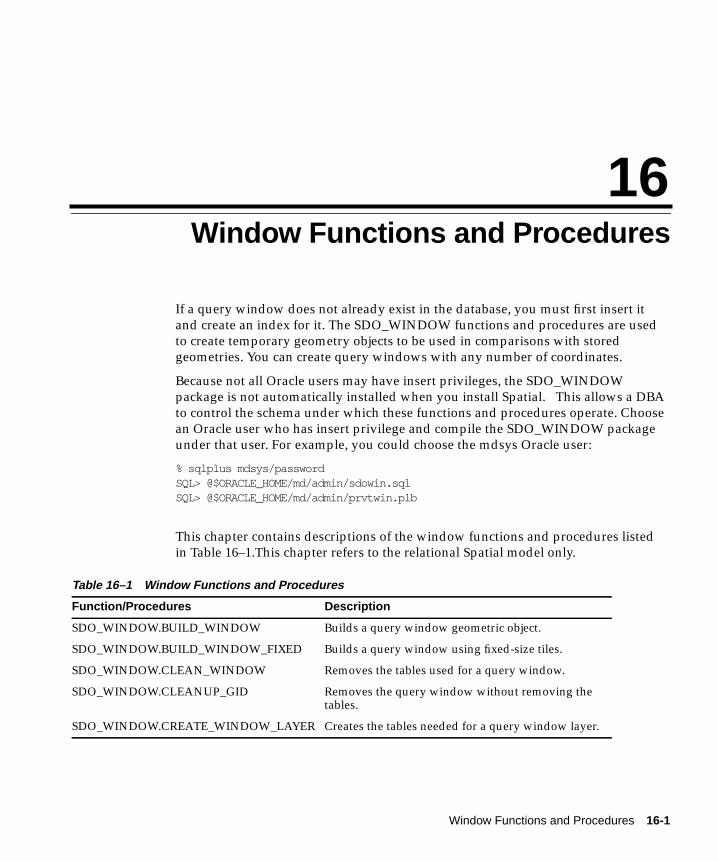
Window Functions and Proc
16
Window Functions and ProceduresIf a query window does not already exist in the database, you must first insert itand create an index for it. The SDO_WINDOW functions and procedures are usedto create temporary geometry objects to be used in comparisons with storedgeometries. You can create query windows with any number of coordinates.
Because not all Oracle users may have insert privileges, the SDO_WINDOWpackage is not automatically installed when you install Spatial. This allows a DBAto control the schema under which these functions and procedures operate. Choosean Oracle user who has insert privilege and compile the SDO_WINDOW packageunder that user. For example, you could choose the mdsys Oracle user:
% sqlplus mdsys/passwordSQL> @$ORACLE_HOME/md/admin/sdowin.sqlSQL> @$ORACLE_HOME/md/admin/prvtwin.plb
This chapter contains descriptions of the window functions and procedures listedin Table 16–1.This chapter refers to the relational Spatial model only.
Table 16–1 Window Functions and Procedures
Function/Procedures Description
SDO_WINDOW.BUILD_WINDOW Builds a query window geometric object.
SDO_WINDOW.BUILD_WINDOW_FIXED Builds a query window using fixed-size tiles.
SDO_WINDOW.CLEAN_WINDOW Removes the tables used for a query window.
SDO_WINDOW.CLEANUP_GID Removes the query window without removing thetables.
SDO_WINDOW.CREATE_WINDOW_LAYER Creates the tables needed for a query window layer.
edures 16-1
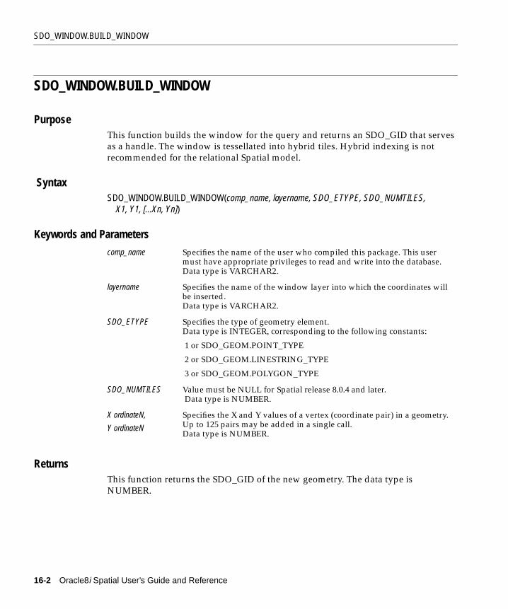
SDO_WINDOW.BUILD_WINDOW
SDO_WINDOW.BUILD_WINDOW
PurposeThis function builds the window for the query and returns an SDO_GID that servesas a handle. The window is tessellated into hybrid tiles. Hybrid indexing is notrecommended for the relational Spatial model.
SyntaxSDO_WINDOW.BUILD_WINDOW(comp_name, layername, SDO_ETYPE, SDO_NUMTILES, X1, Y1, [...Xn, Yn])
Keywords and Parameters
ReturnsThis function returns the SDO_GID of the new geometry. The data type isNUMBER.
comp_name Specifies the name of the user who compiled this package. This usermust have appropriate privileges to read and write into the database.Data type is VARCHAR2.
layername Specifies the name of the window layer into which the coordinates willbe inserted.Data type is VARCHAR2.
SDO_ETYPE Specifies the type of geometry element.Data type is INTEGER, corresponding to the following constants:
1 or SDO_GEOM.POINT_TYPE
2 or SDO_GEOM.LINESTRING_TYPE
3 or SDO_GEOM.POLYGON_TYPE
SDO_NUMTILES Value must be NULL for Spatial release 8.0.4 and later. Data type is NUMBER.
X ordinateN,
Y ordinateN
Specifies the X and Y values of a vertex (coordinate pair) in a geometry.Up to 125 pairs may be added in a single call.Data type is NUMBER.
16-2 Oracle8i Spatial User’s Guide and Reference

SDO_WINDOW.BUILD_WINDOW
Usage NotesThis function inserts the coordinates into the <layername>_SDOGEOM table,tessellates the geometry (creates the index), and returns a unique SDO_GIDcorresponding to the geometry.
You do not need special privileges to execute this function. However, the user whocompiles it does need appropriate privileges to read and write into the database.
When working with Spatial release 8.0.3 tables, the SDO_NUMTILES parameterindicates the number of tiles into which the window should be tessellated. Forrelease 8.0.4 or later, the function reads that information automatically from the<layername>_SDOLAYER table.
Related TopicsSDO_WINDOW.BUILD_WINDOW_FIXED() function
Window Functions and Procedures 16-3

SDO_WINDOW.BUILD_WINDOW_FIXED
SDO_WINDOW.BUILD_WINDOW_FIXED
PurposeThis function builds the window for the query and returns an SDO_GID that servesas a handle. The window is tessellated into fixed-size tiles.
SyntaxSDO_WINDOW.BUILD_WINDOW_FIXED (comp_name, layername, SDO_ETYPE, SDO_TILESIZE, X1, Y1, [...Xn, Yn])
Keywords and Parameters
ReturnsThis function returns the SDO_GID of the new geometry. Data type is NUMBER.
Usage NotesThis function inserts the coordinates into the <layername>_SDOGEOM table,tessellates the geometry (creates the index), and returns a unique SDO_GIDcorresponding to the geometry.
comp_name Specifies the name of the user who compiled this package. This usermust have appropriate privileges to read and write into the database.Data type is VARCHAR2.
layername Specifies the name of the window layer into which the coordinates willbe inserted.Data type is VARCHAR2.
SDO_ETYPE Specifies the type of geometry element.Data type is INTEGER, corresponding to the following constants:
1 or SDO_GEOM.POINT_TYPE
2 or SDO_GEOM.LINESTRING_TYPE
3 or SDO_GEOM.POLYGON_TYPE
SDO_TILESIZE Specifies the number of tessellations required to achieve the desiredfixed-size tiles.Data type is NUMBER.
X ordinateN,
Y ordinateN
Specifies the X and Y values of a vertex (coordinate pair) in a geometry.Up to 125 pairs may be added in a single call.Data type is NUMBER.
16-4 Oracle8i Spatial User’s Guide and Reference

SDO_WINDOW.BUILD_WINDOW_FIXED
You do not need special privileges to execute this function. However, the user whocompiles it does need appropriate privileges to read and write into the database.
Query SDO_LEVEL from the <layername>_SDOLAYER table to pass the correctSDO_TILE_SIZE value to this function.
Related TopicsNone.
Window Functions and Procedures 16-5

SDO_WINDOW.CLEAN_WINDOW
SDO_WINDOW.CLEAN_WINDOW
PurposeThis procedure removes the four tables created in the layer for the query window.
SyntaxSDO_WINDOW.CLEAN_WINDOW (layername);
Keywords and Parameters
Usage NotesTypically, you would build a layer once, and then build multiple windows andperform multiple queries using that layer. After finishing all queries, you canexecute the SDO_WINDOW.CLEAN_WINDOW() procedure to remove the tables.
Related TopicsSDO_WINDOW.CLEANUP_GID
layername Specifies the name of the window layer that mustbe removed.Data type is VARCHAR2.
16-6 Oracle8i Spatial User’s Guide and Reference
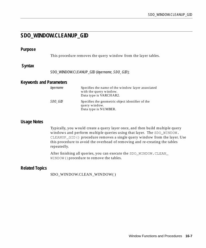
SDO_WINDOW.CLEANUP_GID
SDO_WINDOW.CLEANUP_GID
PurposeThis procedure removes the query window from the layer tables.
SyntaxSDO_WINDOW.CLEANUP_GID (layername, SDO_GID);
Keywords and Parameters
Usage NotesTypically, you would create a query layer once, and then build multiple querywindows and perform multiple queries using that layer. The SDO_WINDOW.CLEANUP_GID() procedure removes a single query window from the layer. Usethis procedure to avoid the overhead of removing and re-creating the tablesrepeatedly.
After finishing all queries, you can execute the SDO_WINDOW.CLEAN_WINDOW()procedure to remove the tables.
Related TopicsSDO_WINDOW.CLEAN_WINDOW( )
layername Specifies the name of the window layer associatedwith the query window.Data type is VARCHAR2.
SDO_GID Specifies the geometric object identifier of thequery window.Data type is NUMBER.
Window Functions and Procedures 16-7
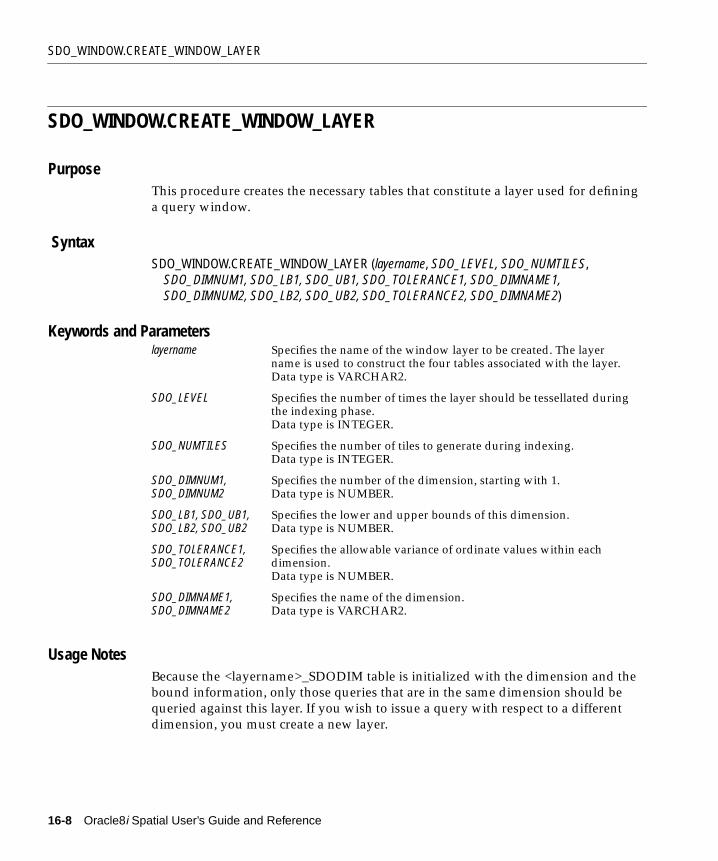
SDO_WINDOW.CREATE_WINDOW_LAYER
SDO_WINDOW.CREATE_WINDOW_LAYER
PurposeThis procedure creates the necessary tables that constitute a layer used for defininga query window.
SyntaxSDO_WINDOW.CREATE_WINDOW_LAYER (layername, SDO_LEVEL, SDO_NUMTILES, SDO_DIMNUM1, SDO_LB1, SDO_UB1, SDO_TOLERANCE1, SDO_DIMNAME1, SDO_DIMNUM2, SDO_LB2, SDO_UB2, SDO_TOLERANCE2, SDO_DIMNAME2)
Keywords and Parameters
Usage NotesBecause the <layername>_SDODIM table is initialized with the dimension and thebound information, only those queries that are in the same dimension should bequeried against this layer. If you wish to issue a query with respect to a differentdimension, you must create a new layer.
layername Specifies the name of the window layer to be created. The layername is used to construct the four tables associated with the layer.Data type is VARCHAR2.
SDO_LEVEL Specifies the number of times the layer should be tessellated duringthe indexing phase.Data type is INTEGER.
SDO_NUMTILES Specifies the number of tiles to generate during indexing.Data type is INTEGER.
SDO_DIMNUM1,SDO_DIMNUM2
Specifies the number of the dimension, starting with 1.Data type is NUMBER.
SDO_LB1, SDO_UB1,SDO_LB2, SDO_UB2
Specifies the lower and upper bounds of this dimension.Data type is NUMBER.
SDO_TOLERANCE1,SDO_TOLERANCE2
Specifies the allowable variance of ordinate values within eachdimension.Data type is NUMBER.
SDO_DIMNAME1,SDO_DIMNAME2
Specifies the name of the dimension.Data type is VARCHAR2.
16-8 Oracle8i Spatial User’s Guide and Reference

SDO_WINDOW.CREATE_WINDOW_LAYER
Related TopicsNone.
Window Functions and Procedures 16-9

SDO_WINDOW.CREATE_WINDOW_LAYER
16-10 Oracle8i Spatial User’s Guide and Reference

Tuning Tips and Sample SQL Scr
A
Tuning Tips and Sample SQL ScriptsThis appendix provides supplemental information to aid in setup, maintenance,and tuning of a spatial database. The scripts and tuning suggestions provided areintended as guidelines that can be adapted to the specific needs of your database.
A.1 Selecting a Spatial ModelThis section describes how to select the best model to fit your needs. Basically, theobject-relational model is preferable in cases where replication and distributeddatabases are not required.
A.1.1 Benefits of the Object-Relational ModelThe following are some of the benefits to using the new object-relational model, asdescribed in Part I of this guide:
■ Additional geometry types: arcs, circles, compound polygons, compound linestrings, and optimized rectangles are supported.
■ Index and query ease of use improved.
■ Indexing is maintained by the Oracle database server.
■ Geometries modeled in a single row, single column.
■ Performance is improved.
A.1.2 Benefits of the Relational ModelThe following are some of the benefits to using the relational model, as described inPart II of this guide:
■ Database replication is supported.
ipts A-1

Tuning Tips
■ Distributed database is supported.
■ Table partitioning and parallel index loading are supported.
When Oracle introduces replication and distributed support for objects in a futurerelease, there will be no benefits to using the relational model.
A.2 Tuning TipsThe following information can be used as a guideline for tuning a spatial database.Unless otherwise specified, the following sections refer to both the object-relationaland relational models.
A.2.1 Data ModelingData modeling is very important when designing a spatial database. You shouldgroup geometries into layers based on the similarity of their attributes. Assumeyour data model uses line strings to represent both roads and rivers. The attributesof a road and the attributes of a river are different. Therefore, these geometriesshould be modeled in two different layers.
In practice, however, if the user of your application will always ask to see both theroads and rivers in a particular region (area of interest), then it may be appropriateto model roads and rivers in the same layer with a common set of attributes.
It is equally important to understand how the data in the various layers will bequeried. If the user of your application is interested in querying the data based on arelationship between the layers, then you should index the layers with the samefixed-size tiling level. For example, a query such as, "Which roads cross rivers?" canachieve better performance if the roads and rivers layers are tiled at the same level.
A.2.2 Understanding the Tiling LevelThe following example explains how tiling is used in Spatial.
Assume you want all the roads (line strings) that overlap a county boundary(polygon) in a spatial database containing 10 million roads. Ignoring Spatialfeatures for a moment, in purely mathematical terms, the problem translates intocomparing all the line segments that make up each road, to the line segments andarea of the county boundary to see if there is any intersection. Thisgeometry-to-geometry comparison is very expensive.
Spatial simplifies this calculation by approximating each geometry with tiles. Theprimary filter in Spatial translates the problem to show all the roads that have a tile
A-2 Oracle8i Spatial User’s Guide and Reference

Tuning Tips
equal to a tile that approximates the polygon. The result of this is a superset of thefinal answer.
The secondary filter (a true geometry-to-geometry comparison) can now beapplied to the candidates that returned from the Spatial primary filter, instead of toevery road in the database.
Picking the correct tile size for fixed-size tiling is one of the most important factorsin attaining good performance. If the tile size you select is too small, you could endup generating thousands of tiles per geometry. Also, the process of tiling a querywindow may become very time consuming.
At the same time, you do not want to choose tiles that are too big. This woulddefeat the purpose of the Spatial primary filter. If the tiles are too big, then toomany geometries are returned from the primary filter and are sent to the morecostly secondary filter.
Keep in mind that the tile size you choose should also depend on if the querywindow (area of interest) is already defined in the database. If the query window isdefined in the database, (that is, if the spatial tables and spatial indexes alreadyexist), then you should choose a smaller tile size. Assume the State layer and theHighway layer are already defined in the database. You could perform a spatialjoin query such as, "which interstate highways go through the state?" withoutincurring the overhead of tiling because the query window is already defined in thedatabase. If, on the other hand, you are creating the query window dynamically,you have to factor in the time it takes to define and index the query window. In thiscase, you should choose a larger tile size to reduce the time it takes to define andindex the query window.
Oracle recommends running the SDO_TUNE.ESTIMATE_TILING_LEVEL()function on your data set to get an initial tiling level estimate. This may not be yourfinal answer, but it will be a good level to start your analysis. In general, it is alsorecommended that you take a random sample of your data and check the queryperformance at different levels of tiling. This would give an indication of what isthe best tiling level for the total data set.
A.2.3 Database SizingProperly choosing rollback segments and tablespaces is important for getting goodperformance from Spatial. Therefore, it is very important to read the Oracle8iAdministrator’s Guide and understand the concepts of tablespaces and rollbacks.
Here are some general guidelines to consider:
Tuning Tips and Sample SQL Scripts A-3

Tuning Tips
■ Always make sure that you have enough rollback space to create a spatialindex.
■ Create separate tablespaces for data layers, indexes, and rollback segments.
■ Properly define initial extents, next extents, and pctincrease for data layertables.
■ Define the initial extent as small as possible when you create the SDO_GEOM_METADATA table in the object-relational model, or the <layername>_SDOLAYER and the <layername>_SDODIM tables in the relational model.These tables contain a few rows each and a small initial extent will reduce theamount of wasted space.
■ Use the SDO_GEOM.VALIDATE_GEOMETRY() procedure to ensure correctnessof geometries in the data sets. Entering incorrect data may lead to unexpectedbehavior in index creation and in the SDO_GEOM.RELATE() functions.
■ Visualizing the indexing tiles, as described in Section A.2.4, can lead to agreater understanding of the tuning process with respect to the size of the tiles.
The following guidelines refer to only the relational model:
■ Always build a B-tree index on the SDO_GID column of the <layername>_SDOGEOM table before attempting to call the SDO_ADMIN.POPULATE_INDEX_FIXED() , SDO_ADMIN.UPDATE_INDEX_FIXED(), SDO_ADMIN.POPULATE_INDEX() , or SDO_ADMIN.UPDATE_INDEX() procedure.
■ For fixed-size tiling, always build a B-tree index on the SDO_CODE column ofthe <layername>_SDOINDEX table before trying any queries using this table.
■ Always build a B-tree index on the SDO_GID column of the <layername>_SDOINDEX table if individual SDO_GIDs will be used as query windows forother Spatial layers.
■ For variable-sized tiling, always build a B-tree index on the SDO_GROUPCODE column of the <layername>_SDOINDEX table before trying anyqueries using this table.
A.2.4 Visualizing the Spatial Index (Drawing Tiles)To select an appropriate tiling level, it may help to visualize the tiles covering yourgeometries. Through visualization, you can determine how many tiles are used foreach object, the size of the tiles, and how well the edges of your geometry arecovered. The basic algorithm is:
1. Select the edges of the tiles represented by the index entries.
A-4 Oracle8i Spatial User’s Guide and Reference

Tuning Tips
2. Plot the tiles on a two-dimensional grid.
3. Plot your geometries on the same grid.
A.2.4.1 Drawing Tiles from the Object-Relational ModelTwo Spatial internal functions have been made visible in order to describe the tiles.These functions were part of a previous release of Oracle Spatial Data Option, andare currently reserved for internal use only. The functions are not recommended forgeneral use, except for this visualization example. Use the following syntax for theinternal functions:
hhcellbndry (sdo_code || sdo_meta, sdo_dimnum, sdo_lb, sdo_ub, hhlength(sdo_code || sdo_meta) {’MIN’ | ’MAX’})
In the following examples, the dimension boundaries were assumed to be -180 to180, and -90 and 90. Also, an index named TEST_INDEX_HL2N6 and a tablenamed TEST are used in the examples.
The SQL queries shown in Example A–1 and Example A–2 can be used to decodeall the index entries in a <layername>_SDOINDEX table. The examples return thecoordinates of the lower-left and upper-right corners of each tile.
Example A–1 View Fixed-Size Tiles for All Geometries
SELECT HHCELLBNDRY(sdo_groupcode || sdo_fixed_meta, 1,-180.0, 180.0, HHLENGTH(sdo_groupcode || sdo_fixed_meta), 'MIN') min_x, HHCELLBNDRY(sdo_groupcode || sdo_fixed_meta, 1,-180.0, 180.0, HHLENGTH(sdo_groupcode || sdo_fixed_meta), 'MAX') max_x, HHCELLBNDRY(sdo_groupcode || sdo_fixed_meta, 2, -90.0, 90.0, HHLENGTH(sdo_groupcode || sdo_fixed_meta), 'MIN') min_y, HHCELLBNDRY(sdo_groupcode || sdo_fixed_meta, 2, -90.0, 90.0, HHLENGTH(sdo_groupcode || sdo_fixed_meta), 'MAX') max_y FROM (SELECT distinct sdo_groupcode, sdo_fixed_meta FROM TEST_INDEX_HL2N6$ a, SDO_INDEX_METADATA b WHERE b.sdo_table_name = 'TEST');
Example A–2 View Variable-Sized Tiles for All Geometries
SELECT HHCELLBNDRY(sdo_code || sdo_meta, 1,-180.0, 180.0, HHLENGTH(sdo_code || sdo_meta), 'MIN') min_x, HHCELLBNDRY(sdo_code || sdo_meta, 1,-180.0, 180.0, HHLENGTH(sdo_code || sdo_meta), 'MAX') max_x, HHCELLBNDRY(sdo_code || sdo_meta, 2, -90.0, 90.0, HHLENGTH(sdo_code || sdo_meta), 'MIN') min_y,
Tuning Tips and Sample SQL Scripts A-5

Tuning Tips
HHCELLBNDRY(sdo_code || sdo_meta, 2, -90.0, 90.0, HHLENGTH(sdo_code || sdo_meta), 'MAX') max_y FROM (SELECT distinct sdo_code, sdo_meta FROM TEST_INDEX_HL2N6$ a);
The SQL queries shown in Example A–3 and Example A–4 can be used to decodethe index entries for a specific geometry stored in a <layername>_SDOINDEX table.
Example A–3 View Fixed-Size Tiles for One Geometry
SELECT HHCELLBNDRY(sdo_groupcode || sdo_fixed_meta, 1,-180.0, 180.0, HHLENGTH(sdo_groupcode || sdo_fixed_meta), 'MIN') min_x, HHCELLBNDRY(sdo_groupcode || sdo_fixed_meta, 1,-180.0, 180.0, HHLENGTH(sdo_groupcode || sdo_fixed_meta), 'MAX') max_x, HHCELLBNDRY(sdo_groupcode || sdo_fixed_meta, 2, -90.0, 90.0, HHLENGTH(sdo_groupcode || sdo_fixed_meta), 'MIN') min_y, HHCELLBNDRY(sdo_groupcode || sdo_fixed_meta, 2, -90.0, 90.0, HHLENGTH(sdo_groupcode || sdo_fixed_meta), 'MAX') max_y FROM (SELECT distinct sdo_groupcode, sdo_fixed_meta FROM TEST_INDEX_HL2N6$ a, SDO_INDEX_METADATA b WHERE b.sdo_table_name = 'TEST' AND a.sdo_rowid = 'AAAA59AAFAADzAZAAA');
Example A–4 View Variable-Sized Tiles for One Geometry
SELECT HHCELLBNDRY(sdo_code || sdo_meta, 1,-180.0, 180.0, HHLENGTH(sdo_code || sdo_meta), 'MIN') min_x, HHCELLBNDRY(sdo_code || sdo_meta, 1,-180.0, 180.0, HHLENGTH(sdo_code || sdo_meta), 'MAX') max_x, HHCELLBNDRY(sdo_code || sdo_meta, 2, -90.0, 90.0, HHLENGTH(sdo_code || sdo_meta), 'MIN') min_y, HHCELLBNDRY(sdo_code || sdo_meta, 2, -90.0, 90.0, HHLENGTH(sdo_code || sdo_meta), 'MAX') max_y FROM TEST_INDEX_HL2N6$ WHERE sdo_rowid = 'AAAA59AAFAADzAZAAA';
A.2.4.2 Drawing Tiles from the Relational ModelThe spatial index is represented internally as a linear quadtree. The structure usedto represent the linear quadtree is composed of two components: a data componentand a metadata component. The data component of the linear quadtree is stored inthe SDO_CODE column, and the metadata component is stored in the SDO_METAcolumn.
A-6 Oracle8i Spatial User’s Guide and Reference

Tuning Tips
The SDO_META column is not required for spatial queries. However, bycombining the SDO_META column with the SDO_CODE column, the tiles of anygeometry or of the entire data set can be decoded. This capability allows the tiles tobe visualized.
Two Spatial internal functions have been made visible in order to describe the tiles.These functions were part of a previous release of Oracle Spatial Data Option, andare currently reserved for internal use only. The functions are not recommended forgeneral use, except for this visualization example. Use the following syntax for theinternal functions:
hhcellbndry (sdo_code || sdo_meta, sdo_dimnum, sdo_lb, sdo_ub, hhlength(sdo_code || sdo_meta) {’MIN’ | ’MAX’})
In the following examples, the dimension boundaries were assumed to be -180 to180, and -90 and 90. The dimensional information is stored in the <layername>_SDODIM table.
If you used SDO_ADMIN.UPDATE_INDEX_FIXED() or SDO_ADMIN.POPULATE_INDEX_FIXED() to generate your spatial index, replace "sdo_code || sdo_meta"with sdo_tile in the SQL statements that follow.
The SQL query shown in Example A–5 can be used to decode all the index entriesin a <layername>_SDOINDEX table. The example returns the coordinates of thelower-left and upper-right corners of each tile.
Example A–5 View Fixed-Sized Tiles for All Geometries Using the Relational Model
SELECT hhcellbndry (sdo_code || sdo_meta, 1, -180.000000000, 180.000000000, hhlength (sdo_code || sdo_meta), 'MIN') min_x, hhcellbndry (sdo_code || sdo_meta, 1, -180.000000000, 180.000000000, hhlength (sdo_code || sdo_meta), 'MAX') max_x, hhcellbndry (sdo_code || sdo_meta, 2, -90.000000000, 90.000000000, hhlength (sdo_code || sdo_meta), 'MIN') min_y, hhcellbndry (sdo_code || sdo_meta, 2, -90.000000000, 90.000000000, hhlength (sdo_code || sdo_meta), 'MAX') max_yFROM (SELECT DISTINCT sdo_code, sdo_meta FROM <layername>_sdoindex);
The SQL query shown Example A–6 in can be used to decode the index entries fora specific geometry stored in a <layername>_SDOINDEX table:
Tuning Tips and Sample SQL Scripts A-7
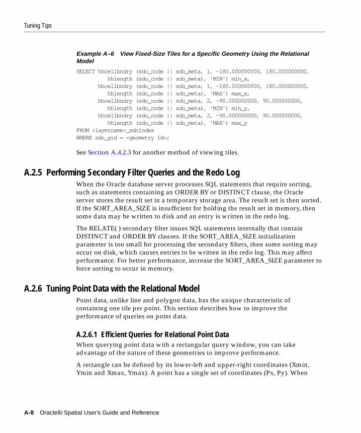
Tuning Tips
Example A–6 View Fixed-Size Tiles for a Specific Geometry Using the RelationalModel
SELECT hhcellbndry (sdo_code || sdo_meta, 1, -180.000000000, 180.000000000, hhlength (sdo_code || sdo_meta), 'MIN') min_x, hhcellbndry (sdo_code || sdo_meta, 1, -180.000000000, 180.000000000, hhlength (sdo_code || sdo_meta), 'MAX') max_x, hhcellbndry (sdo_code || sdo_meta, 2, -90.000000000, 90.000000000, hhlength (sdo_code || sdo_meta), 'MIN') min_y, hhcellbndry (sdo_code || sdo_meta, 2, -90.000000000, 90.000000000, hhlength (sdo_code || sdo_meta), 'MAX') max_yFROM <layername>_sdoindexWHERE sdo_gid = <geometry id>;
See Section A.4.2.3 for another method of viewing tiles.
A.2.5 Performing Secondary Filter Queries and the Redo LogWhen the Oracle database server processes SQL statements that require sorting,such as statements containing an ORDER BY or DISTINCT clause, the Oracleserver stores the result set in a temporary storage area. The result set is then sorted.If the SORT_AREA_SIZE is insufficient for holding the result set in memory, thensome data may be written to disk and an entry is written in the redo log.
The RELATE( ) secondary filter issues SQL statements internally that containDISTINCT and ORDER BY clauses. If the SORT_AREA_SIZE initializationparameter is too small for processing the secondary filters, then some sorting mayoccur on disk, which causes entries to be written in the redo log. This may affectperformance. For better performance, increase the SORT_AREA_SIZE parameter toforce sorting to occur in memory.
A.2.6 Tuning Point Data with the Relational ModelPoint data, unlike line and polygon data, has the unique characteristic ofcontaining one tile per point. This section describes how to improve theperformance of queries on point data.
A.2.6.1 Efficient Queries for Relational Point DataWhen querying point data with a rectangular query window, you can takeadvantage of the nature of these geometries to improve performance.
A rectangle can be defined by its lower-left and upper-right coordinates (Xmin,Ymin and Xmax, Ymax). A point has a single set of coordinates (Px, Py). When
A-8 Oracle8i Spatial User’s Guide and Reference
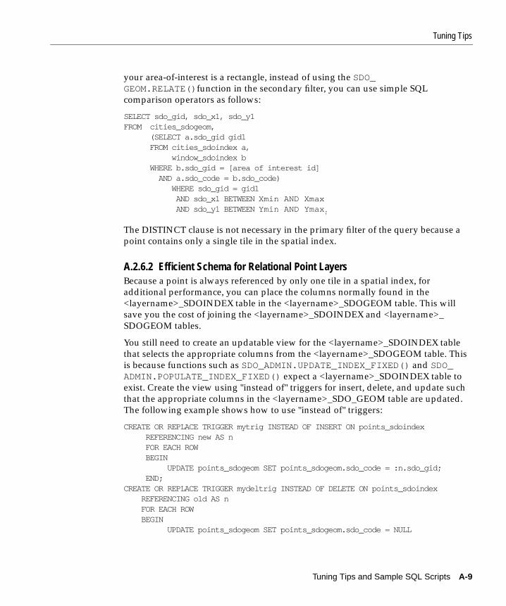
Tuning Tips
your area-of-interest is a rectangle, instead of using the SDO_GEOM.RELATE()function in the secondary filter, you can use simple SQLcomparison operators as follows:
SELECT sdo_gid, sdo_x1, sdo_y1FROM cities_sdogeom, (SELECT a.sdo_gid gid1 FROM cities_sdoindex a, window_sdoindex b WHERE b.sdo_gid = [area of interest id] AND a.sdo_code = b.sdo_code) WHERE sdo_gid = gid1 AND sdo_x1 BETWEEN Xmin AND Xmax AND sdo_y1 BETWEEN Ymin AND Ymax ;
The DISTINCT clause is not necessary in the primary filter of the query because apoint contains only a single tile in the spatial index.
A.2.6.2 Efficient Schema for Relational Point LayersBecause a point is always referenced by only one tile in a spatial index, foradditional performance, you can place the columns normally found in the<layername>_SDOINDEX table in the <layername>_SDOGEOM table. This willsave you the cost of joining the <layername>_SDOINDEX and <layername>_SDOGEOM tables.
You still need to create an updatable view for the <layername>_SDOINDEX tablethat selects the appropriate columns from the <layername>_SDOGEOM table. Thisis because functions such as SDO_ADMIN.UPDATE_INDEX_FIXED() and SDO_ADMIN.POPULATE_INDEX_FIXED() expect a <layername>_SDOINDEX table toexist. Create the view using "instead of" triggers for insert, delete, and update suchthat the appropriate columns in the <layername>_SDO_GEOM table are updated.The following example shows how to use "instead of" triggers:
CREATE OR REPLACE TRIGGER mytrig INSTEAD OF INSERT ON points_sdoindex REFERENCING new AS n FOR EACH ROW BEGIN UPDATE points_sdogeom SET points_sdogeom.sdo_code = :n.sdo_gid; END;CREATE OR REPLACE TRIGGER mydeltrig INSTEAD OF DELETE ON points_sdoindex REFERENCING old AS n FOR EACH ROW BEGIN UPDATE points_sdogeom SET points_sdogeom.sdo_code = NULL
Tuning Tips and Sample SQL Scripts A-9
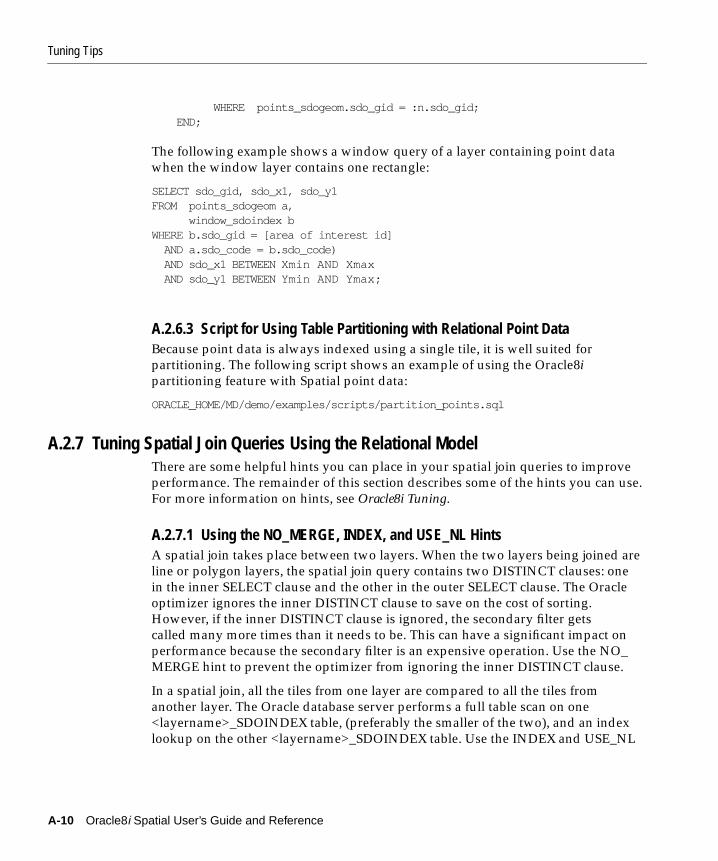
Tuning Tips
WHERE points_sdogeom.sdo_gid = :n.sdo_gid; END;
The following example shows a window query of a layer containing point datawhen the window layer contains one rectangle:
SELECT sdo_gid, sdo_x1, sdo_y1FROM points_sdogeom a, window_sdoindex bWHERE b.sdo_gid = [area of interest id] AND a.sdo_code = b.sdo_code) AND sdo_x1 BETWEEN Xmin AND Xmax AND sdo_y1 BETWEEN Ymin AND Ymax;
A.2.6.3 Script for Using Table Partitioning with Relational Point DataBecause point data is always indexed using a single tile, it is well suited forpartitioning. The following script shows an example of using the Oracle8ipartitioning feature with Spatial point data:
ORACLE_HOME/MD/demo/examples/scripts/partition_points.sql
A.2.7 Tuning Spatial Join Queries Using the Relational ModelThere are some helpful hints you can place in your spatial join queries to improveperformance. The remainder of this section describes some of the hints you can use.For more information on hints, see Oracle8i Tuning.
A.2.7.1 Using the NO_MERGE, INDEX, and USE_NL HintsA spatial join takes place between two layers. When the two layers being joined areline or polygon layers, the spatial join query contains two DISTINCT clauses: onein the inner SELECT clause and the other in the outer SELECT clause. The Oracleoptimizer ignores the inner DISTINCT clause to save on the cost of sorting.However, if the inner DISTINCT clause is ignored, the secondary filter getscalled many more times than it needs to be. This can have a significant impact onperformance because the secondary filter is an expensive operation. Use the NO_MERGE hint to prevent the optimizer from ignoring the inner DISTINCT clause.
In a spatial join, all the tiles from one layer are compared to all the tiles fromanother layer. The Oracle database server performs a full table scan on one<layername>_SDOINDEX table, (preferably the smaller of the two), and an indexlookup on the other <layername>_SDOINDEX table. Use the INDEX and USE_NL
A-10 Oracle8i Spatial User’s Guide and Reference

Tuning Tips
hints to force the optimizer to perform the full table scan on the smaller of the two<layername>_SDOINDEX tables being compared.
The following example shows a spatial join between line (road) and polygon(county) data. The query answers the question, "Which counties intersect majorroads?"
SELECT /*+ cost ordered use_nl(COUNTY_sdogeom) index (COUNTY_sdogeom NAME_OF_SDO_GID_INDEX) */ COUNTY_sdogeom.SDO_GID, COUNTY_sdogeom.SDO_ESEQ, COUNTY_sdogeom.SDO_SEQ, COUNTY_sdogeom.SDO_X1,COUNTY_sdogeom.SDO_Y1, COUNTY_sdogeom.SDO_X2,COUNTY_sdogeom.SDO_Y2, COUNTY_sdogeom.SDO_X3,COUNTY_sdogeom.SDO_Y3, COUNTY_sdogeom.SDO_X4,COUNTY_sdogeom.SDO_Y4, COUNTY_sdogeom.SDO_X5,COUNTY_sdogeom.SDO_Y5, COUNTY_sdogeom.SDO_X6,COUNTY_sdogeom.SDO_Y6, COUNTY_sdogeom.SDO_X7,COUNTY_sdogeom.SDO_Y7, COUNTY_sdogeom.SDO_X8,COUNTY_sdogeom.SDO_Y8FROM (SELECT DISTINCT gid_a gid1 FROM (SELECT /*+ index (a NAME_OF_SDO_CODE_INDEX)
index (b NAME_OF_SDO_CODE_INDEX)use_nl (a b)no_merge */
DISTINCT a.sdo_gid gid_a, b.sdo_gid gid_b FROM COUNTY_SDOINDEX a, MAJOR_ROAD_SDOINDEX b WHERE a.sdo_code = b.sdo_code) WHERE sdo_geom.relate('COUNTY', gid_a, 'ANYINTERACT', 'MAJOR_ROAD',gid_b) <> 'FALSE'), COUNTY_sdogeomWHERE COUNTY_sdogeom.sdo_gid = gid1;
A.2.7.2 Spatial Join Queries with Point LayersThe following example shows a spatial join between line (road) and point (streetaddress) data. The query answers the question, "which addresses are on a majorroad?"
SELECT /*+ cost ordered use_nl (STREET_ADDRESS_sdogeom) index (STREET_ADDRESS_sdogeom NAME_OF_SDO_GID_INDEX)
Tuning Tips and Sample SQL Scripts A-11

Tuning Tips
*/ STREET_ADDRESS_sdogeom.SDO_GID, STREET_ADDRESS_sdogeom.SDO_X1, STREET_ADDRESS_sdogeom.SDO_Y1FROM (SELECT DISTINCT gid_a gid1 FROM (SELECT /*+ index (a NAME_OF_SDO_CODE_INDEX) index (b NAME_OF_SDO_CODE_INDEX) use_nl (a b) */ a.sdo_gid gid_a, b.sdo_gid gid_b FROM STREET_ADDRESS_SDOINDEX a, MAJOR_ROAD_SDOINDEX b WHERE a.sdo_code = b.sdo_code) WHERE sdo_geom.relate('STREET_ADDRESS', gid_a, 'ANYINTERACT', 'MAJOR_ROAD',gid_b) <> 'FALSE'), COUNTY_sdogeomWHERE COUNTY_sdogeom.sdo_gid = gid1;
The inner DISTINCT clause is not necessary for spatial joins where one of thelayers contains point data. Therefore, the NO_MERGE hint is not necessary. This isbecause points contain only one tile in the spatial index.
The following example shows a spatial join between polygon (county) and point(street address) data. The query generates a report that displays how manyaddresses are associated with each county.
If you can assume that each street address is associated with a single county, youcan significantly speed up this query. Because points contain only a single tile inthe spatial index, any street address tile that matches only one county tile in theprimary filter does not need to go through the expensive secondary filter.
SELECT county_gid, count(street_gid)FROM (SELECT poly.sdo_gid county_gid, street.sdo_gid street_gid FROM STREET_ADDRESS_sdoindex street, (SELECT sdo_code county_sdo_code, count(sdo_gid) interacts FROM CENSUS_COUNTY_sdoindex GROUP by sdo_code ) counts, CENSUS_COUNTY_sdoindex poly WHERE street.sdo_code = counts.county_sdo_code AND poly.sdo_code = street.sdo_code AND (counts.interacts = 1 OR sdo_geom.relate('STREET_ADDRESS', street.sdo_gid,
A-12 Oracle8i Spatial User’s Guide and Reference
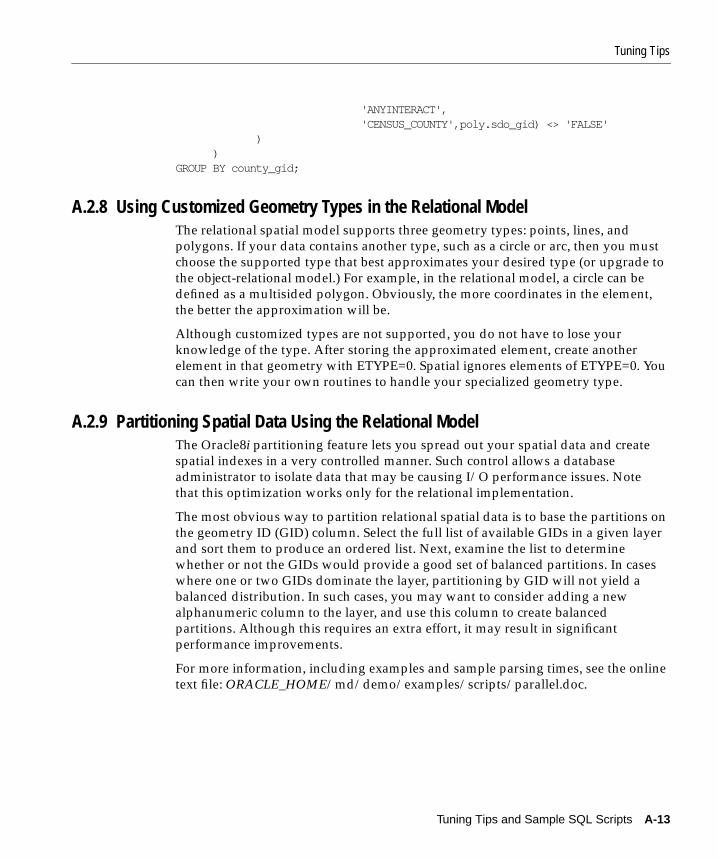
Tuning Tips
'ANYINTERACT', 'CENSUS_COUNTY',poly.sdo_gid) <> 'FALSE' ) )GROUP BY county_gid;
A.2.8 Using Customized Geometry Types in the Relational ModelThe relational spatial model supports three geometry types: points, lines, andpolygons. If your data contains another type, such as a circle or arc, then you mustchoose the supported type that best approximates your desired type (or upgrade tothe object-relational model.) For example, in the relational model, a circle can bedefined as a multisided polygon. Obviously, the more coordinates in the element,the better the approximation will be.
Although customized types are not supported, you do not have to lose yourknowledge of the type. After storing the approximated element, create anotherelement in that geometry with ETYPE=0. Spatial ignores elements of ETYPE=0. Youcan then write your own routines to handle your specialized geometry type.
A.2.9 Partitioning Spatial Data Using the Relational ModelThe Oracle8i partitioning feature lets you spread out your spatial data and createspatial indexes in a very controlled manner. Such control allows a databaseadministrator to isolate data that may be causing I/O performance issues. Notethat this optimization works only for the relational implementation.
The most obvious way to partition relational spatial data is to base the partitions onthe geometry ID (GID) column. Select the full list of available GIDs in a given layerand sort them to produce an ordered list. Next, examine the list to determinewhether or not the GIDs would provide a good set of balanced partitions. In caseswhere one or two GIDs dominate the layer, partitioning by GID will not yield abalanced distribution. In such cases, you may want to consider adding a newalphanumeric column to the layer, and use this column to create balancedpartitions. Although this requires an extra effort, it may result in significantperformance improvements.
For more information, including examples and sample parsing times, see the onlinetext file: ORACLE_HOME/md/demo/examples/scripts/parallel.doc.
Tuning Tips and Sample SQL Scripts A-13

Tuning Tips
A.2.10 Parallel Loading and Indexing of Spatial Data Using the Relational ModelOn a multiprocessor system, you can use parallel execution to improve bothloading times and spatial index creation times. Note that this optimization worksonly for the relational implementation.
When using partitioned tables, as described in Section A.2.9, you can achievefurther performance gains by loading and indexing geometries in parallel. Thepartitioned tables can be loaded by selecting from non-partitioned source tables, orusing the SQL*Loader utility. Parallel threads (one for each partition,) can besubmitted to load the partitioned table. For information on parallel loading, see thedescription of the SQL*Loader utility in Oracle8i Utilities.
You can also create spatial indexes in parallel by creating a number of views orlayers. Create each layer with a range of GIDs, with corresponding <layername>_SDOLAYER and <layername>_SDODIM tables. For example, the followingstatements create the necessary views for the first 300 GIDs in a table:
CREATE VIEW a_sdogeom AS SELECT * FROM a_sdogeom WHERE sdo_gid BETWEEN 1 and 100;CREATE VIEW a_sdodim AS SELECT * FROM a_sdodim;CREATE VIEW a_sdolayer AS SELECT * FROM a_sdolayer;
Next, create the index table as a partitioned table. Create a partition for each rangeof GIDs for which you created a view.
CREATE INDEX a_sdoindex (sdo_gid NUMBER, sdo_code RAW(255), sdo_meta RAW(255))INITRANS 4STORAGE (initial 2M next 1M pctincrease 0 freelist groups 12 freelists 19)PARTITION BY RANGE (sdo_gid)(PARTITION a_idx1 VALUES LESS THAN (300) TABLESPACE sdo_data . . . );
To create the index, submit SDO_ADMIN.POPULATE_INDEX() commands for eachof the partitions. The threads will independently build their corresponding indexes,
A-14 Oracle8i Spatial User’s Guide and Reference

Scripts for Spatial Indexing Using the Relational Model
with significant performance improvements over the non-partitioned,single-threaded model.
For more information, including examples and sample parsing times, see the onlinetext file: ORACLE_HOME/md/demo/examples/scripts/parallel.doc.
A.3 Scripts for Spatial Indexing Using the Relational ModelSpatial provides sample SQL script files to show how to use dynamic SQL in aPL/SQL block to create layer tables for spatially indexed data. The scripts areavailable after installation in the ORACLE_HOME/md/admin directory.
The following sections describe the cr_spatial_index.sql and crlayer.sql scripts.
A.3.1 cr_spatial_index.sql ScriptThe cr_spatial_index.sql script file shows an example of updating the spatial indexfor a layer, and executing a commit after every 50 GIDs have been entered.
The procedures SDO_ADMIN.POPULATE_INDEX() and SDO_ADMIN.POPULATE_INDEX_FIXED() operate as a single transaction. To reduce the amount of rollbackrequired to execute these procedures, you can write a routine similar to that in cr_spatial_index.sql. This script loops and calls SDO_ADMIN.UPDATE_INDEX_FIXED() for each GID, committing after every 50 GIDs.
-- cr_spatial_index.sql---- Note: if geometries do not span more than 1 row, you can remove-- the DISTINCT qualifier from the SELECT statement.--declare cursor c1 is SELECT DISTINCT sdo_gid from POLYGON_SDOGEOM; gid number; i number;begin i := 0; for r in c1 loop begin gid:= r.sdo_gid; sdo_admin.update_index_fixed(’POLYGON’, gid, 15, FALSE, FALSE, FALSE); exception when others then dbms_output.put_line(’error for gid’||to_char(gid)||’: ’||SQLERRM ); end; i:= i + 1;
Tuning Tips and Sample SQL Scripts A-15
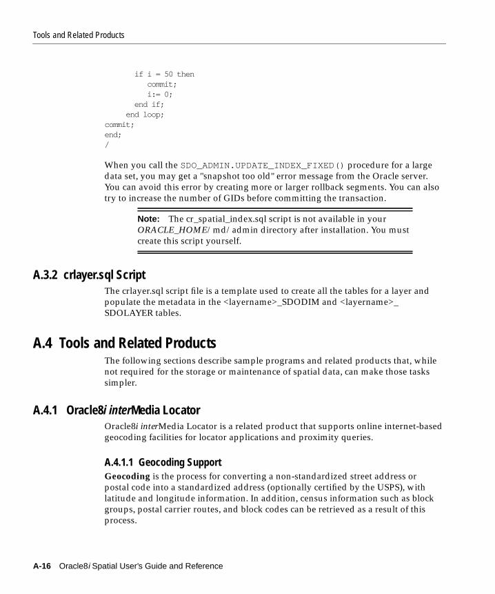
Tools and Related Products
if i = 50 then commit; i:= 0; end if; end loop;commit;end;/
When you call the SDO_ADMIN.UPDATE_INDEX_FIXED() procedure for a largedata set, you may get a "snapshot too old" error message from the Oracle server.You can avoid this error by creating more or larger rollback segments. You can alsotry to increase the number of GIDs before committing the transaction.
A.3.2 crlayer.sql ScriptThe crlayer.sql script file is a template used to create all the tables for a layer andpopulate the metadata in the <layername>_SDODIM and <layername>_SDOLAYER tables.
A.4 Tools and Related ProductsThe following sections describe sample programs and related products that, whilenot required for the storage or maintenance of spatial data, can make those taskssimpler.
A.4.1 Oracle8i interMedia LocatorOracle8i interMedia Locator is a related product that supports online internet-basedgeocoding facilities for locator applications and proximity queries.
A.4.1.1 Geocoding SupportGeocoding is the process for converting a non-standardized street address orpostal code into a standardized address (optionally certified by the USPS), withlatitude and longitude information. In addition, census information such as blockgroups, postal carrier routes, and block codes can be retrieved as a result of thisprocess.
Note: The cr_spatial_index.sql script is not available in yourORACLE_HOME/md/admin directory after installation. You mustcreate this script yourself.
A-16 Oracle8i Spatial User’s Guide and Reference

Tools and Related Products
The interMedia Locator option provides an interface to the online geocodingservice provided by Qualitative Marketing Service, Inc. (QMS). You can usePL/SQL stored procedure functions to geocode an address, and record and fetch allthe information into two predefined objects from the QMS Web site. The first objectis of type SDO_GEOMETRY, and it contains the spatial longitude and latitudeinformation stored as point data. The second object returned is GEOCODE_RESULT which contains text fields of a standardized address and other fieldsmentioned previously such as postal carrier route or block code.
For more information about this online service, see the following Web site:
http://www.centrus-software.com/oracle
For more information about interMedia Locator, see Oracle8i interMedia LocatorUser’s Guide and Reference.
A.4.1.2 Compatibility with Spatial ObjectsinterMedia Locator is a subset of Oracle8i Spatial and, therefore, is completelycompatible with Spatial objects. The index uses the same set of metadata tables, forinstance. One difference is that interMedia Locator locates only points, whileSpatial supports multiple geometry types.
The LOCATOR_WITHIN_DISTANCE() operator is similar to the SDO_GEOM.WITHIN_DISTANCE( ) operator.
The interMedia Locator version of the WITHIN_DISTANCE operator takes a newparameter in the last string: units=[mile,meter,ft] . This allows you to searchby units. The functionality in the Spatial version is only an estimation on thesurface of the earth, and not exact distance or driving distance.
A.4.1.3 Sample Locator CodeSample scripts are available in the following directory after you install Oracle8iinterMedia Locator:
$ORACLE_HOME/md/demo/geocoder
To migrate data between products, type ocimig , and prompts will guide youthrough the process, which is similar to using SQL*Loader or the export/importutilities.
Tuning Tips and Sample SQL Scripts A-17

Tools and Related Products
A.4.2 Spatial Viewer on UNIX/Motif for Relational ModelA sample geometry viewer, sdodemo, is available for UNIX systems using a Motifinterface. This viewer displays geometries stored using the relational model.
A.4.2.1 Installation and SetupThe following steps are required to set up and run the Motif application:
1. Set the environment variables:
setenv MD_VIEWER <full_pathname>/sdo_motif_demo/srcsetenv XENVIRONMENT $MD_VIEWER/app-defaults/resource_filealias sdodemo $MD_VIEWER/bin/demo
2. Run the following as mdsys:
$ORACLE_HOME/md/admin/sdowin.sql$ORACLE_HOME/md/admin/prvtwin.plb$MD_VIEWER/sql_scripts/my_window.sql$MD_VIEWER/sql_scripts/my_win.sql
3. If you are using a Sun Solaris system, a compiled version of $MD_VIEWER/bin/demo has been shipped with Spatial. Go to step 4.
If you are using a UNIX operating system other than Solaris, you need torecompile the viewer. A makefile is included only for Sun Solaris systems. Youmay need to make some system-specific modifications.
cd $MD_VIEWERmake -f makefile8.sun cleanmake -f makefile8.sun
4. Create an alias for the sample program:
alias sdodemo $MD_VIEWER/bin/demo
5. Run the sample program:
sdodemo
A.4.2.2 Connecting to a Database and Viewing GeometriesWhen you run the sample sdodemo program, you will be prompted for an Oracleuser name, password, and alias if the database resides on a remote machine.
A-18 Oracle8i Spatial User’s Guide and Reference
Tools and Related Products
Two windows will pop up, one where geometries are drawn, and a second withseveral buttons. Click the CHOOSE LAYER button and select a layer.
The extent of the map will initially be the values stored in the <layername>_SDODIM table for the current layer. You can then click the ZOOM TO EXTENTbutton, and the map extent will be set to the true extent of your data. Note that thetime it takes to perform ZOOM TO EXTENT depends on the amount of data inyour <layername>_SDOGEOM table.
A.4.2.3 Using the Sample ViewerThe text for all queries is displayed in the UNIX shell where you are running thesdodemo program.
There are three radio buttons at the top of the control panel. These buttonsdetermine which query is executed when you click the PERFORM QUERY button:
■ PRIM & SEC - performs a primary and secondary filter.
■ PRIMARY FILTER ONLY - performs a primary filter only query.
■ DRAW ALL - selects everything in the <layername>_SDOGEOM table. Thisdoes not perform a spatial query.
To perform a spatial query:
1. Click either the PRIM & SEC or the PRIMARY FILTER ONLY radio button.
2. Click either SELECT BOX, SELECT CIRCLE, or SELECT POLYGON, and drawthe area of interest on the map.
3. Click the PERFORM QUERY button, and the geometries will display on thebase map.
You can look at individual geometries by clicking the SHOW GIDS button. You canalso click the SHOW ALL TILES button to look at index tiles. This can help youtune your spatial index. See Section A.2.4 for another method of drawing tiles.
A.4.3 Spatial Visualizer on Windows NT for the Object-Relational ModelThe Spatial Visualizer is a sample program used to demonstrate two things. First, itis an example of using dynamic linking libraries to wrap Oracle Call Interface(OCI) and Spatial functions into C++ classes. Second, the program provides asimple visualizer that can display Spatial objects.
Tuning Tips and Sample SQL Scripts A-19

Tools and Related Products
A.4.3.1 Compiling and Running the Sample ProgramTo compile the Spatial Visualizer sample program, first unzip the following file intoyour work directory: ORACLE_HOME/md/demos/NT/DEMO_Visualizer.zip.This creates the following subdirectories:
■ include - contains header files
■ bin and lib - contain output files
■ SDOConnCur - contains a project for creating a dynamic link library (DLL)
■ VisualSDO - contains another project for creating an executable (EXE) file
Next, make sure your Visual C++ IDE has the correct directory settings for usingOCI and common header files. To ensure this, click Tools... Options... Directories,and then perform the following tasks:
1. Click ’Include files’ to add the OCI include path (for example,C:\ORANT\OCI80\include) and the common include path for your projects(for example, Myprojects\include).
2. Click ’Library files’ to add the OCI library path (for example,C:\ORANT\OCI80\lib\msvc) and the common library path for your projects(for example, Myprojects\lib).
3. Type ’SDOConnCur\SDOConnCur.dsw’ and click Open to compileSDOConnCur.dll.
4. Type ’VisualSDO\VisualSDO.dsw’ and click Open to create VisualSDO.exe.
A.4.3.2 Usage NotesConsider the following when using this sample program:
■ ’SDOConnCur’: This project creates a DLL (SDOConnCur.dll) to wrap OCI andSDO functions into C++ classes, so that users of this DLL can benefit fromOracle Call Interface (OCI) without knowing how to make OCI calls.
■ 'VisualSDO’: This project creates an executable file (VisualSDO.exe) based onSDOConnCur.dll. It is a simple visualizer that can display Oracle8i Spatialgeometry objects.
■ All the files and directories under ORACLE_HOME/md/demos/NT arecomponents of the Spatial Visualizer demonstration program. They should beused for demonstration purposes only.
■ The workspaces are created with Visual C++ 6.0, and might not be compatiblewith previous versions.
A-20 Oracle8i Spatial User’s Guide and Reference

Tools and Related Products
■ The ZIP file (DEMO_Visualizer.zip) contains all the contents under thisdirectory. Due to system dependencies, copy the ZIP file only to a Windows NTsystem.
Tuning Tips and Sample SQL Scripts A-21

Tools and Related Products
A-22 Oracle8i Spatial User’s Guide and Reference

Installation, Compatibility, and Migration Iss
B
Installation, Compatibility, and MigrationIssues
This appendix provides information concerning installation, compatibility, andmigration between various Oracle Spatial product releases.
Beginning with Spatial Data Option 7.3.3, all interfaces are supported in eachsubsequent release. A spatial application built for and using the 7.3.3 spatial dataoption interfaces will work with an 8.0.4, 8.0.5, or 8.1.3 database server. Theimplementations of these interfaces have changed and therefore PL/SQL packagesfrom older versions of the spatial cartridge will not work with newer versions ofthe Oracle database server. Therefore, you must upgrade both server and Spatial atthe same time if you wish to use older spatial applications with new Oracle8ireleases.
Spatial must always be synchronized with the Oracle database server on upgradeor downgrade. In both cases, Spatial must be re-installed.
B.1 IntroductionSpatial release 8.1 requires Oracle8i Enterprise Edition and the Objects Option.Spatial release 8.1 has been redesigned to use various Oracle8i object andextensibility features. Many of the features this option depends on are new inrelease 8.1 of the database server. Therefore, there are many compatibility andmigration issues that need to addressed in this release of Spatial. This appendixoutlines the database and application compatibility issues.
Database compatibility issues exist because the product uses extensible indexingand object types in 8.1, and therefore if an 8.1 database instance is downgraded to8.0.5, then the spatial objects must be deleted and re-created. In this case, the datamust be exported and imported into 8.0.5. This, and other requirements, result in
ues B-1

Installation Details
application incompatibility. An 8.1 Spatial application will likely use the newspatial operators and therefore will not work with an 8.0.5 instance unless it canidentify the Spatial version and dynamically change its spatial queries.
An upgrade or downgrade of the database server version requires a correspondingupgrade or downgrade of Spatial. If an 8.0.5 server is upgraded to 8.1, Spatial alsohas to be upgraded. The reason has to do with using dynamic SQL in PL/SQL, andInvoker's Rights in 8.1. Similarly, if an 8.1 server is downgraded, Spatial must bedowngraded too. Lastly, if an 8.1 server is running in 8.0 compatibility mode, thenSpatial will experience various failures unless it is reconfigured for 8.0.5. You canreconfigure the product by running the downgrade script: c813d805.sql.
In summary:
■ Spatial release and the Oracle database server release must match
■ Upgrade and downgrade scripts must be run when upgrading or downgradingbetween 8.0.5 and 8.1
■ Spatial will work in 8.0 compatibility mode for an 8.1 database server if andonly if the downgrade script is run and users or applications only attempt touse the relational implementation of the product
B.2 Installation DetailsTo install Spatial, the script catmd.sql in the ORACLE_HOME/md/admin directorymust be run as user mdsys. The mdsys user should be created with the set ofprivileges listed in ORACLE_HOME/MD/mdprivs.sql, and with both default andtemporary tablespace.
Installation of Spatial requires that the COMPATIBLE init.ora parameter is set to8.1.0.0.0 or higher. This is required for the creation and definition of Spatial indextypes and operators. Thus, if the database was created with a compatibilityparameter value of 8.0.x.x.x, the DBA must shut down the database and restartwith COMPATIBLE=8.1.x.x.x.
B.2.1 Changing from 8.1 to 8.0 Compatibility ModeIf Spatial has been installed and the database compatibility needs to be reset to8.0.x.x.x from 8.1.x.x.x, then do the following:
1. Determine if there is any user data that contains instances of the typeMDSYS.SDO_GEOMETRY. That is, determine if any user table has a column oftype MDSYS.SDO_GEOMETRY and has data in it.
B-2 Oracle8i Spatial User’s Guide and Reference

Compatibility Details
2. If there are instances, delete all spatial indexes on these columns. Delete thedata in these columns or delete these columns and tables. If there are noinstances, go on to the next step.
3. Run the script c813d805.sql in ORACLE_HOME/md/admin. This will deleteall spatial objects that require 8.1 compatibility. That is, all the object-relationalimplementation objects for Oracle8i Spatial will be deleted. The relationalimplementation available in release 8.0.x.x.x will remain installed andaccessible.
4. While connected as SYSTEM, enter the following:
ALTER DATABASE RESET COMPATIBILITY SHUTDOWN Change the init.ora parameter COMPATIBLE=8.1.0.0.0 STARTUP
After running ORACLE_HOME/MD/c813d805.sql, resetting the databasecomptability to 8.1.x.x.x from 8.0.x.x.x requires running the script ORACLE_HOME/MD/c805u813.sql to re-install and enable the object-relationalimplementation of Spatial.
B.3 Compatibility DetailsAll releases of the Spatial product provide a set of predefined spatial data types,topological operators such as RELATE(), and a spatial indexing mechanism. TheOracle8i Spatial release differs from previous ones in that it:
■ Uses object types (a varray-based type called SDO_GEOMETRY to storeordinates)
■ Supports new spatial data types, namely arcs and circles
■ Has new spatial operators (SDO_WITHIN_DISTANCE) and functions, SDO_POLY_UNION, SDO_BUFFER, SDO_POLY_INTERSECT, and SDO_POLY_XOR
■ Utilizes Dynamic SQL in PL/SQL
■ Allows Invoker's Rights
■ Tessellates a geometry as a whole rather than an element at a time
All interfaces preceding Oracle8i are maintained, but the package bodies have beenchanged to use the above features. Thus for Oracle8i, the Spatial packages must bereinstalled to use these interfaces even if the compatibility parameter is set to 8.0.
Installation, Compatibility, and Migration Issues B-3

Data Migration Issues
No data migration is needed and the 7.3.4/8.0.4 spatial applications will workwithout modification. Any OCI-specific migration issues must be handled in thesame manner as they would have to be for any OCI application.
The 7.3.4/8.0.4 to 8.1.3 upgrade requirements are the same. Upgrade both Oracle8iand Spatial. Perform all the necessary steps for an upgrade. Your spatialapplications will continue to work as before.
Downgrading from 8.0.5 or earlier releases to a previous release of the server andSpatial requires no special steps specific to the Spatial implementation. However,this situation is different for Oracle8i. In Oracle8i, Spatial uses objects andextensible indexing. Therefore, it creates Oracle8i specific database objects that arenot compatible with previous releases of the database server. When youdowngrade the server and Spatial from Oracle8i to 8.0.5, a spatial-specificdowngrade script must be executed to remove all the spatial geometry type,indexmethod type, and spatial operator definitions.
B.4 Data Migration IssuesBeginning with 7.3.3, all subsequent releases can work with spatial data fromprevious releases. That is no data migration is required. The situation is different inOracle8i because Spatial now allows two storage mechanisms. If you want thefeatures specific to Oracle8i, such as extensible indexing and spatial operators, thenyou must migrate your spatial data from the 7.3.3 columns-of-numbers style to theSDO_GEOMETRY storage scheme. Spatial provides a stored procedure and samplecode that demonstrates one way of migrating data and metadata.
Migrating data on downgrades is more complex. Spatial provides OCIdemonstration programs to read SDO_GEOMETRY instances and store them in an8.0.5 spatial schema for comparable data. The demo also addresses issues related tothe changes in the way metadata is stored in Oracle8i compared to previousreleases. The complexity arises from the following:
■ From 7.3.4 onward, Spatial has an UNSUPPORTED_GEOMETRY type that isalways used in conjunction with a bounding box or polygon, used for indexingpurposes, which encloses the spatial object. This did not exist in release 7.3.3.
■ From 8.1.3 onward, Spatial supports arcs, circles, arc strings, and geometriesmade up of a mixture of arc and line segments.
You cannot store arcs and circles in any release earlier than Oracle8i. And youcannot use data from a 7.3.4 or later spatial layer in 7.3.3 if it contains instances oftype UNSUPPORTED_GEOMETRY (etype=0).
B-4 Oracle8i Spatial User’s Guide and Reference

Partitioning Legacy Point
C
Partitioning Legacy Point DataSpatial has undergone an architectural change, beginning with the 7.3.3 release.The emphasis on partitioned tables has been replaced by the improved spatialindexing features.
Spatial provides the essential functions, procedures, and scripts for using andmanaging both spatially indexed data and partitioned point data. The informationin this appendix is relevant only to users who have not yet migrated to the newdata model. For all other users, spatial indexing is preferred and recommended.
C.1 OverviewPartitioning is a technique where data is loaded into tables that automaticallysubdivide when a predefined maximum size is reached. During subdivision, datais moved from the parent partition to the child partitions and the parent partition isdeleted. Storage parameters for child partitions are inherited from the root partitionand can be changed at any time.
A partitioned table has a partition key that is an HHCODE column created byencoding multidimensional point data using the SDO_ENCODE() function. In thepartitioning process, at each subdivision, data is subdivided into 2n partitionswhere n is the number of dimensions encoded in the HHCODE column. You canencode up to 32 dimensions using Spatial.
Note: The functions described in this appendix will be removedin a future release.
Data C-1

Partitioning Process
C.2 Partitioning ProcessThis guide does not attempt to provide the information necessary for fully utilizingtable partitioning for point data. Existing users who need to use this methodshould continue to use their Spatial Data Option 7.3.2 documentation. Thefollowing is a high-level description of the partitioning process:
1. Start with an Oracle8i table containing multidimensional point data. Forexample, columns of X and Y coordinate data from a blueprint or map.
2. Create a table or view from the original Oracle8i table containing the columnsyou want, plus a new HHCODE column.
An HHCODE column is a new data type used to encode multiple dimensionsinto a unique orderable value. HHCODE is not a point, but rather a boundedcell representing an object space in as many dimensions as have been defined.An HHCODE data type is defined as RAW(255).
3. Create the HHCODE data type by encoding multiple dimensions into a singlevalue using the SDO_ENCODE() function. The HHCODE data type will beused as the partition key.
4. Register a partitioned table in the Spatial data dictionary using the SDO_ADMIN.REGISTER_PARTITION_INFO() procedure. This procedure takes thename of a table, the name of the partition key column, and the maximumnumber of records you want stored in a partition before it subdivides.
5. Call the SDO_ADMIN.PARTITION() procedure with the name of the table orview containing the partition key column and the tablespace in which thepartitions should be created. In this step, the data is partitioned based ondimensions encoded in the HHCODE column.
6. If the underlying table has constraints, grants, or triggers, the owner needs touse the SDO_ADMIN.PROPAGATE_GRANTS() procedure to set those propertieson the partitions.
7. To add more partitioned point data, load the data into a table, and call SDO_ADMIN.PARTITION() again. The dimensions encoded in the HHCODEcolumn must have the same boundaries to be loaded into the existingpartitioned table.
8. After you have added data multiple times, or after adding or deleting a largeamount of data, there may be partitions that exceed the high-water mark orthere may be partitions that can be merged. Call the SDO_ADMIN.REPARTITION() procedure to reorganize the partitioned table.
C-2 Oracle8i Spatial User’s Guide and Reference

Scripts for the Deprecated Partitioned Point Data Model
Repartitioning is a computation-intensive task that should be performed onlywhen necessary.
C.3 Scripts for the Deprecated Partitioned Point Data ModelThis section describes the following scripts:
■ altpart.sql
■ drppart.sql
■ sdogrant.sql
Although the scripts described in this section are available, the recommendedapproach is to use Oracle8i partitioning and spatial indexing.
C.3.1 altpart.sql ScriptThe altpart.sql script file shows how to use dynamic SQL in a PL/SQL procedure tomodify all partitions of a Spatial partitioned table.
The Spatial data dictionary view used in this SQL script requires that a registeredSpatial partitioned table is specified. If the table is not registered, you can use theUSER_TABLES view to select all the partitioned tables from the user’s schema. Touse the USER_TABLES view, enter the following syntax:
SQL> SELECT TABLENAME FROM user_tables WHERE TABLENAME LIKE2> ’% tablename _P%’;
C.3.2 drppart.sql ScriptThe drppart.sql script file shows how to use dynamic SQL in a PL/SQL procedureto drop (remove) all partitions of a Spatial partitioned table. After running thisprocedure, you must run the SDO_ADMIN.DROP_PARTITION_INFO() procedure.
The Spatial data dictionary view used in this SQL script requires that a registeredSpatial partitioned table is specified. If the table is not registered, you can use theUSER_TABLES view to select all the partitioned tables from the user’s schema. Touse the USER_TABLES view, use the following syntax:
SQL> SELECT TABLENAME FROM user_tables WHERE TABLENAME LIKE2> ’% tablename _P%’;
Partitioning Legacy Point Data C-3

Administrative Functions for the Deprecated Model
C.3.3 sdogrant.sql ScriptThe sdogrant.sql script file contains an administrative procedure, PROPAGATE_GRANTS(), which is used after calling the SDO_ADMIN.PARTITION() or SDO_ADMIN.REPARTITION() procedures.
This procedure must first be compiled by running the sdogrant.sql file. ThePROPAGATE_GRANTS() procedure is callable only by the user who compiled it.
C.4 Administrative Functions for the Deprecated ModelTable C–1 lists the procedures that can be used with partitioned point data. Theseprocedures are neither required nor compatible with the geometry-based dataformat.
Table C–1 Administrative Procedures for Partitioned Point Data
Procedure Data Structure Description
SDO_ADMIN.ALTER_HIGH_WATER_MARK Partitioned points Alters the high-water mark of a partitioned table.
SDO_ADMIN.DROP_PARTITION_INFO Partitioned points Removes a partitioned table.
SDO_ADMIN.PARTITION Partitioned points Places data into partitioned tables.
SDO_ADMIN.PROPAGATE_GRANTS Partitioned points Propagates the grants on the registered underlyingtable to the various partitions.
SDO_ADMIN.REGISTER_PARTITION_INFO
Partitioned points Creates a partitioned spatial table.
SDO_ADMIN.REPARTITION Partitioned points Reorganizes a table based on the sorted values of thedata contained within it.
SDO_ADMIN.VERIFY_PARTITIONS Partitioned points Checks for the existence of a table.
C-4 Oracle8i Spatial User’s Guide and Reference

SDO_ADMIN.ALTER_HIGH_WATER_MARK
SDO_ADMIN.ALTER_HIGH_WATER_MARK
PurposeThis procedure alters the high-water mark of a partitioned spatial table. Thehigh-water mark defines how many records can be stored in a partition before itsubdivides. The table must exist and be registered in the Spatial data dictionary.
This procedure is for use only with partitioned point data.
SyntaxSDO_ADMIN.ALTER_HIGH_WATER_MARK (tablename, high_water_mark)
Keywords and Parameters
Usage NotesNone.
The following example changes the high-water mark to 5000 records for the table1partitioned spatial table:
SQL> EXECUTE SDO_ADMIN.ALTER_HIGH_WATER_MARK(’table1’, 5000);
Related Topics■ SDO_ADMIN.REPARTITION() procedure
■ altpart.sql sample SQL script file
tablename Specifies the name of the partitioned table.Data type is VARCHAR2.
high_water_mark Specifies the new high-water mark for the table.Data type is INTEGER.
Partitioning Legacy Point Data C-5

SDO_ADMIN.DROP_PARTITION_INFO
SDO_ADMIN.DROP_PARTITION_INFO
PurposeThis procedure removes a partitioned spatial table from the Spatial data dictionary.The table must exist and must be registered in the Spatial data dictionary.
This procedure is used only with partitioned point data.
SyntaxSDO_ADMIN.DROP_PARTITION_INFO (tablename)
Keywords and Parameters
Usage NotesThis procedure does not remove the spatial table and its associated partition tablesfrom the user’s schema. For a description of how to remove a partitioned spatialtable from the user’s schema, see the drppart.sql sample SQL script file describedin Section C.3.2.
The following example removes the table1 table from the Spatial data dictionary:
SQL> EXECUTE SDO_ADMIN.DROP_PARTITION_INFO(’table1’);
Related Topics■ drppart.sql sample SQL script file
tablename Specifies the name of the partitioned table.Data type is VARCHAR2.
C-6 Oracle8i Spatial User’s Guide and Reference
SDO_ADMIN.PARTITION
SDO_ADMIN.PARTITION
PurposeThis procedure places data into partitioned tables based on the sorted order ofencoded dimensional values.
This procedure is used only with partitioned point data.
SyntaxSDO_ADMIN.PARTITION (owner.source_table, tablename, parallel, guess, plummet_flag[,tablespace] )
Keywords and Parameters
owner.source_table Specifies the Oracle8i table or view of the table containing thepartition key column.Data type is VARCHAR2.
tablename Specifies the name of the table to partition.Data type is VARCHAR2.
parallel Specifies the degree of parallelism for an operation on a singleinstance.Data type is INTEGER.
guess Specifies the estimated largest common level of all the potentialpartitions to be created from data in the source_table. The commonlevel of a partition is the number of levels of resolution of thecommon HHCODE for the partition.Data type is INTEGER.
plummet_flag Specifies if the common HHCODE for all the potential partitions to becreated from data in the source_table contains the maximum possiblecommon level. If TRUE, the common HHCODE for each potentialpartition contains the maximum possible common level. If FALSE, thecommon HHCODE for each potential partition contains the minimumpossible common level.Default value is FALSE.Data type is BOOLEAN.
tablespace Specifies the tablespace in which the partitions should be created.Default is the tablespace of the underlying table.
Partitioning Legacy Point Data C-7

SDO_ADMIN.PARTITION
Usage NotesConsider the following when using this procedure:
■ The maximum size of the partitioned tables is determined by the high-watermark of the partitioned spatial table.
■ To perform this procedure, first load the original data into an Oracle8i tableusing a utility such as SQL*Loader. After the data is loaded, encode the datausing the appropriate combination of Spatial data conversion functions. Theencoded data is used as the partition key column. The partition key column isprovided as either a column in the Oracle8i table or as a view of that table.
■ For more information on specifying the degree of parallelism, see the Oracle8iTuning manual.
The following example partitions the table1 partitioned spatial table with datacontained in the source1 table:
SQL> EXECUTE SDO_ADMIN.PARTITION(’source1’,’table1’,1,10,FALSE);
Related Topics■ SDO_ADMIN.REGISTER_PARTITION_INFO( ) procedure
C-8 Oracle8i Spatial User’s Guide and Reference

SDO_ADMIN.PROPAGATE_GRANTS
SDO_ADMIN.PROPAGATE_GRANTS
PurposeThis procedure is used to propagate the grants on the underlying table to thepartitions.
This procedure is used only with partitioned point data.
SyntaxSDO_ADMIN.PROPAGATE_GRANTS (tablename)
Keywords and Parameters
Usage NotesThis procedure is used after calls to SDO_ADMIN.PARTITION() or SDO_ADMIN.REPARTITION() . It must be called by the owner of the partition.
This procedure must be compiled prior to use. See Section C.3.3.
The following example propagates grants from the TABLE1 partitioned spatialtable:
SQL> EXECUTE SDO_ADMIN.PROPAGATE_GRANTS(’TABLE1’);
Related Topics■ SDO_ADMIN.PARTITION( ) procedure
■ SDO_ADMIN.REPARTITION( ) procedure
tablename Specifies the name of the partitioned table.Data type is VARCHAR2.
Partitioning Legacy Point Data C-9
SDO_ADMIN.REGISTER_PARTITION_INFO
SDO_ADMIN.REGISTER_PARTITION_INFO
PurposeThis procedure creates a partitioned spatial table entry in the Spatial datadictionary, and defines the partition key column and the high-water mark for thetable.
This procedure is used only with partitioned point data.
SyntaxSDO_ADMIN.REGISTER_PARTITION_INFO (tablename, column, high_water_mark)
Keywords and Parameters
Usage NotesThe SQL CREATE TABLE statement is used to create the partitioned spatial table,with the partition key column defined as RAW(255), prior to calling this procedure.
The following example registers the TABLE1 partitioned spatial table:
SQL> EXECUTE SDO_ADMIN.REGISTER_PARTITION_INFO(’table1’,2> ’hhcolumn’, 1000);
Related Topics■ SDO_ADMIN.PARTITION( ) procedure
tablename Specifies the name of the partitioned table.Data type is VARCHAR2.
column Specifies the name of the partition key column for the table.Data type is VARCHAR2.
high_water_mark Specifies the number of records to store in a partition before thepartition subdivides.Data type is INTEGER.
C-10 Oracle8i Spatial User’s Guide and Reference

SDO_ADMIN.REPARTITION
SDO_ADMIN.REPARTITION
PurposeThis procedure reorganizes a partitioned spatial table based on the sorted order ofencoded dimensional values already contained in it. The table must exist and mustbe registered in the Spatial data dictionary.
This procedure is used only with partitioned point data.
SyntaxSDO_ADMIN.REPARTITION (tablename, parallel, [tablespace])
Keywords and Parameters
Usage NotesConsider the following when using this procedure:
■ The tablespace variable is optional. If you do not supply a tablespace name, thepartitions are created in the same tablespace as the registered partition table.
■ The maximum size of the reorganized partition tables is determined by thehigh-water mark of the partitioned spatial table.
The following example repartitions the table1 partitioned spatial table:
SQL> EXECUTE SDO_ADMIN.REPARTITION(’table1’, 1);
Related Topics■ SDO_ADMIN.ALTER_HIGH_WATER_MARK( ) procedure
tablename Specifies the name of the partitioned table.Data type is VARCHAR2.
parallel Specifies the degree of parallelism for an operation on a single instance.Data type is INTEGER.
tablespace Specifies the name of the tablespace in which to create the partition.Data type is VARCHAR2.
Partitioning Legacy Point Data C-11

SDO_ADMIN.VERIFY_PARTITIONS
SDO_ADMIN.VERIFY_PARTITIONS
PurposeThis procedure checks if the partitioned spatial table exists, if it is registered in theSpatial data dictionary, and if the partition key column exists as defined in theSpatial data dictionary.
This procedure is used only with partitioned point data.
SyntaxSDO_ADMIN.VERIFY_PARTITIONS (tablename)
Keywords and Parameters
Usage NotesThis procedure can generate the following errors depending on the results of theverification:
■ SDO 13113 (Oracle table does not exist)
■ SDO 13108 (spatial table not found)
■ SDO 13111 (spatial table has no partition key defined)
■ SDO 13129 (HHCODE column not found)
The following example verifies the table1 partitioned spatial table:
SQL> EXECUTE SDO_ADMIN.VERIFY_PARTITIONS(’table1’);
Related Topics■ SDO_ADMIN.REGISTER_PARTITION_INFO( ) procedure
tablename Specifies the name of the table.Data type is VARCHAR2.
C-12 Oracle8i Spatial User’s Guide and Reference

Data Functions
C.5 Data FunctionsThe functions described in this section are not required for creating or maintaininga spatial database, however, they are provided for convenience in working withlegacy data in partitioned point data tables. They are used with SQL SELECT,INSERT, UPDATE, and DELETE statements to perform the following:
■ Generate dimensions from bounded, hierarchical, or date data values
■ Encode and decode dimensions
■ Retrieve bounded, hierarchical, or date data values from dimensions
When using these functions in basic SQL statements, use the form:SDO_<function>. When using the functions inside a PL/SQL block, use a period (.)instead of the underscore (_).
This section contains descriptions of the spatial functions listed in Table C–2.
Table C–2 Partitioned Point Data Functions
Function Purpose
SDO_BVALUETODIM Creates a dimension from bounded data values.
SDO_COMPARE Evaluates the relationship between two objectsdescribed by HHCODEs.
SDO_DATETODIM Creates a dimension from an Oracle DATE datatype.
SDO_DECODE Extracts a single dimension from an HHCODE.
SDO_ENCODE Creates an HHCODE by combining dimensions todescribe an area or point.
SDO_TO_BVALUE Extracts a bounded data value from a dimension.
SDO_TO_DATE Extracts an Oracle DATE data type from adimension.
Partitioning Legacy Point Data C-13

SDO_BVALUETODIM
SDO_BVALUETODIM
PurposeThis function creates a dimension from a bounded value, which is a valuecontained in a set of values expressed as a lower boundary and an upper boundary.
SyntaxSDO_BVALUETODIM (value, lower_boundary, upper_boundary, decimal_scale)
Keywords and Parameters
ReturnsThis function returns a dimension. The data type is RAW.
Usage Notes The following example shows the SDO_BVALUETODIM() function:
SQL> INSERT INTO sourcetable1 (SAMPLENAME,DATA_PT)2> VALUES (’SAMPLE1’,SDO_ENCODE(SDO_BVALUETODIM(10,-100,100,7),3> SDO_BVALUETODIM(20,-100,100,7));
Related Topics■ SDO_ENCODE( ) function
■ SDO_TO_BVALUE( ) function
value Specifies the value for the particular dimension.Data type is NUMBER.
lower_boundary Specifies the lower boundary of the dimension range.Data type is NUMBER.
upper_boundary Specifies the upper boundary of the dimension range.Data type is NUMBER.
decimal_scale Specifies the number of digits to the right of the decimal point.Data type is NUMBER.
C-14 Oracle8i Spatial User’s Guide and Reference

SDO_COMPARE
SDO_COMPARE
PurposeThis function evaluates the relationship between an area or point described by anHHCODE and another HHCODE, or a range of HHCODEs expressed as an upperbound and lower bound.
SyntaxSDO_COMPARE (hhcode_expression, {hhcode_expression | lower_bound_HHCODE,upper_bound_HHCODE})
Keywords and Parameters
ReturnsThis function returns one of the following keywords:
■ ENCLOSES
■ EQUAL
■ INSIDE
■ OUTSIDE
■ OVERLAP
The data type is VARCHAR2.
Usage NotesThe following example selects all points that fall within the givenmultidimensional range:
SQL> SELECT SDO_GID FROMlayer1 _SDOINDEX WHERE2> SDO_COMPARE(SDO_MAXCODE,
hhcode_expression Specifies an expression that evaluates to an HHCODE.Data type is RAW.
lower_bound_HHCODE Specifies the lower bound HHCODE expression.Data type is RAW.
upper_bound_HHCODE Specifies the upper bound HHCODE expression.Data type is RAW.
Partitioning Legacy Point Data C-15

SDO_COMPARE
3> SDO_ENCODE(5,5),4> SDO_ENCODE(25,25))=’INSIDE’;
The following example selects GIDs based on interaction between their spatialindex tiles:
SQL> SELECT SDO_GID FROMlayer1 _SDOINDEX A, layer2 _SDOINDEX B2> WHERE SDO_COMPARE(A.SDO_CODE,B.SDO_CODE) != ’OUTSIDE’;
Related Topics■ SDO_GEOM.RELATE( ) function
C-16 Oracle8i Spatial User’s Guide and Reference

SDO_DATETODIM
SDO_DATETODIM
PurposeThis function creates a dimension from an Oracle DATE data type. The componentnumber determines the level of resolution of the date in the dimension.
SyntaxSDO_DATETODIM (date [, component])
Keywords and Parameters
ReturnsThis function returns a dimension. The data type is RAW.
Usage NotesYou must use a valid Oracle date format string.
The following example shows the SDO_DATETODIM() function:
SQL> INSERT INTO sourcetable1 (SAMPLENAME,DATA_PT)2> VAUES(’SAMPLE1’,SDO_ENCODE(SDO_DATETODIM(TO_DATE(’19-Jul-96’),3> SDO_BVALUETODIM(100,-1000,1000,7)));
date Specifies the calendar date.Data type is DATE.
component Specifies the level of resolution. The componentnumber values are defined as follows:
1 accurate to year2 accurate to month3 accurate to day4 accurate to hour5 accurate to minute6 accurate to second
The default value is 6.Data type is INTEGER.
Partitioning Legacy Point Data C-17

SDO_DATETODIM
Related Topics■ SDO_ENCODE( ) function
■ SDO_TO_DATE( ) function
C-18 Oracle8i Spatial User’s Guide and Reference

SDO_DECODE
SDO_DECODE
PurposeThis function extracts a single dimension from an HHCODE.
SyntaxSDO_DECODE (hhcode_expression, dimension_number)
Keywords and Parameters
ReturnsThis function returns a dimension. The data type is RAW.
Usage NotesThe SDO_DECODE() function is called once for each dimension to be decoded.
The following example shows the SDO_DECODE() function:
SQL> SELECT2> SDO_TO_BVALUE(SDO_DECODE(DATA_PT,1),1,6),3> SDO_TO_BVALUE(SDO_DECODE(DATA_PT,2),-100,100),4> SDO_TO_DATE(SDO_DECODE(DATA_PT,3))5> FROM sourcetable1 WHERE SAMPLENAME=’SAMPLE1’;
Related Topics■ SDO_TO_BVALUE( ) function
■ SDO_TO_DATE( ) function
hhcode_expression Specifies an expression that evaluates to an HHCODE.Data type is RAW.
dimension_number Specifies the dimension number to extract.Data type is INTEGER.
Partitioning Legacy Point Data C-19

SDO_ENCODE
SDO_ENCODE
PurposeThis function combines dimensions to create the HHCODE that describes an areaor point.
SyntaxSDO_ENCODE (dimension1[,dimension2 ...])
Keywords and Parameters
ReturnsThis function returns an HHCODE. The data type is RAW.
Usage NotesConsider the following when using this function:
■ When encoding dimensions, the order of the dimensions in the parameter listmust be consistent for all rows within the table.
■ This function can encode up to 32 dimensions.
The following example shows the SDO_ENCODE() function:
SQL> INSERT INTO sourcetable1 (SAMPLENAME,DATA_PT)2> VALUES (’SAMPLE1’,SDO_ENCODE(SDO_BVALUETODIM(50,-100, 100, 10),3> SDO_BVALUETODIM(30,-100,100,10),4> SDO_DATETODIM(TO_DATE(’05-Jul-96’),3)));
Related Topics■ SDO_BVALUETODIM( ) function
■ SDO_DATETODIM( ) function
dimension Specifies an expression created by the SDO_BVALUETODIM or SDO_DATETODIM functions.Data type is RAW.
C-20 Oracle8i Spatial User’s Guide and Reference

SDO_TO_BVALUE
SDO_TO_BVALUE
PurposeThis function returns the original bounded data value of a dimension.
SyntaxSDO_TO_BVALUE (dimension, lower_boundary, upper_boundary)
Keywords and Parameters
ReturnsThis function returns a bounded data value. The data type is NUMBER.
Usage NotesThis function returns a number that is the value for a dimension within thespecified range. This is not necessarily the range for which the dimension wasoriginally created.
The following example shows the SDO_TO_BVALUE() function:
SQL> SELECT (SDO_TO_BVALUE(SDO_DECODE(DATA_PT,2),-100,100)2> FROM sourcetable1 WHERE SAMPLENAME=’SAMPLE1’;
Related Topics■ SDO_DECODE( ) function
■ SDO_BVALUETODIM( ) function
dimension Specifies the dimension.Data type is RAW.
lower_boundary Specifies the lower boundary of the dimension range.Data type is NUMBER.
upper_boundary Specifies the upper boundary of the dimension range.Data type is NUMBER.
Partitioning Legacy Point Data C-21

SDO_TO_DATE
SDO_TO_DATE
PurposeThis function returns the original date value of a dimension.
SyntaxSDO_TO_DATE (dimension)
Keywords and Parameters
ReturnsThis function returns an Oracle DATE data type.
Usage NotesThe following example shows the SDO_TO_DATE() function:
SQL> SELECT SDO_TO_DATE(SDO_DECODE(DATA_PT,3))2> FROM sourcetable1 WHERE SAMPLENAME=’SAMPLE1’;
Related Topics■ SDO_DATETODIM( ) function
■ SDO_DECODE( ) function
dimension Specifies the dimension.Data type is RAW.
C-22 Oracle8i Spatial User’s Guide and Reference
Data Dictionary
C.6 Data DictionaryThe Spatial data dictionary is a set of tables owned by the database user mdsys. Anextension to the Oracle8i data dictionary, it automatically maintains informationabout spatial tables, columns, and partitions. The Spatial data dictionary is createdduring the installation process. All nonspatial attribute information is maintainedin the Oracle8i data dictionary.
The Spatial data dictionary has public views that provide extensive informationabout spatial tables. This section contains descriptions of the views that areavailable.
The following views are publicly available:
■ ALL_MD_COLUMNS
■ ALL_MD_DIMENSIONS
■ ALL_MD_EXCEPTIONS
■ ALL_MD_LOADER_ERRORS
■ ALL_MD_PARTITIONS
■ ALL_MD_TABLES
■ ALL_MD_TABLESPACES
■ DBA_MD_COLUMNS
■ DBA_MD_DIMENSIONS
■ DBA_MD_EXCEPTIONS
■ DBA_MD_LOADER_ERRORS
■ DBA_MD_PARTITIONS
■ DBA_MD_TABLES
■ DBA_MD_TABLESPACES
■ USER_MD_COLUMNS
Note: Only the partitioned point routines use the Spatial datadictionary.
Partitioning Legacy Point Data C-23

Data Dictionary
■ USER_MD_DIMENSIONS
■ USER_MD_EXCEPTIONS
■ USER_MD_LOADER_ERRORS
■ USER_MD_PARTITIONS
■ USER_MD_TABLES
■ USER_MD_TABLESPACES
ALL_MD_COLUMNS Returns a list of all columns that are part of spatial tables.
WARNING: Do not delete or modify any of the tables in themdsys account. This corrupts the Spatial data dictionary.
Column Description
OWNER owner of the object
MD_TABLE_NAME name of the spatial table
COLUMN_NAME name of the column
DATA_TYPE data type of the column
DATA_LENGTH length of the column in bytes
DATA_PRECISION scale for NUMBER data type, binary precision forFLOAT data type, and NULL for all other data types
DATA_SCALE digits to right of decimal point in an HHCODE column or anumber
NDIM number of dimensions in the HHCODE column(It is NULL for all other data types.)
MAX_LEVEL maximum number of levels in the column
NULLABLE indicates if column allows NULL values
PARTITION_KEY indicates if column is the partition key column; only one isallowed per partitioned table
COLUMN_ID sequence number of the column as created
DEFAULT_LENGTH length of the default value for the column
C-24 Oracle8i Spatial User’s Guide and Reference

Data Dictionary
ALL_MD_DIMENSIONSReturns a list of all dimensions that are part of HHCODE columns.
ALL_MD_EXCEPTIONSContains information about spatial tables that should be removed (dropped) as aresult of some failed operation, such as a failed load.
NUM_DISTINCT number of distinct values in each column of the table
LOW_VALUE lowest value for tables with three or fewer rows(It is the second-lowest value in the column for tables with morethan three rows.)
HIGH_VALUE highest value for tables with three or fewer rows(It is the second-highest value in the column for tables withmore than three rows.)
Column Description
OWNER owner of the object
MD_TABLE_NAME name of the spatial table
COLUMN_NAME name of the column
DIMENSION_NAME name of the dimension
DIMENSION_NUMBER dimension number
LOWER_BOUND lower boundary of the dimension range
UPPER_BOUND upper boundary of the dimension range
SCALE scale of the dimension
RECURSION_LEVEL number of levels encoded in the HHCODE column
Column Description
OWNER owner of the object
NAME object name
OPERATION operation during which the failure occurred
CCHH common code HHCODE
Column Description
Partitioning Legacy Point Data C-25

Data Dictionary
ALL_MD_LOADER_ERRORS Contains the current status of a file that was loaded into a table using SD*Loader.
ALL_MD_PARTITIONS Returns a list of all the partitioned tables that are part of a user-accessible spatialtable.
ALL_MD_TABLESReturns a list of all the user-accessible spatial tables.
Column Description
OWNER owner of the object
MD_TABLE_NAME spatial table name
FILENAME SLF file name
ROWS_LOADED number of rows loaded before failure
Column Description
OWNER owner of the object
MD_TABLE_NAME name of the spatial table
PARTITION_TABLE_NAME name of the partitioned table
CLASS class of partition: NODE or LEAF
COMMON_LEVEL number of levels of resolution of the common HHCODEcolumn for the partition
COMMON_HHCODE common HHCODE substring for the partition
OFFLINE_STATUS status of partition: ONLINE or OFFLINE
ARCHIVE_DATE date of last archive
Column Description
OWNER owner of the table
MD_TABLE_NAME name of the spatial table
CLASS class of table: PARTITIONED or NON-PARTITIONED
PTAB_SEQ number of last partitioned table created
C-26 Oracle8i Spatial User’s Guide and Reference
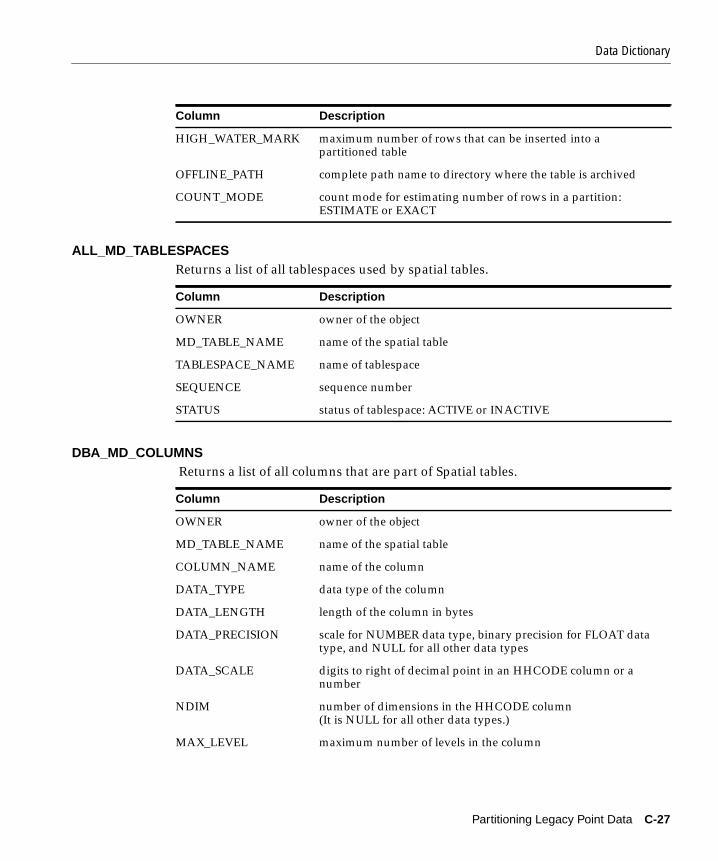
Data Dictionary
ALL_MD_TABLESPACESReturns a list of all tablespaces used by spatial tables.
DBA_MD_COLUMNS Returns a list of all columns that are part of Spatial tables.
HIGH_WATER_MARK maximum number of rows that can be inserted into apartitioned table
OFFLINE_PATH complete path name to directory where the table is archived
COUNT_MODE count mode for estimating number of rows in a partition:ESTIMATE or EXACT
Column Description
OWNER owner of the object
MD_TABLE_NAME name of the spatial table
TABLESPACE_NAME name of tablespace
SEQUENCE sequence number
STATUS status of tablespace: ACTIVE or INACTIVE
Column Description
OWNER owner of the object
MD_TABLE_NAME name of the spatial table
COLUMN_NAME name of the column
DATA_TYPE data type of the column
DATA_LENGTH length of the column in bytes
DATA_PRECISION scale for NUMBER data type, binary precision for FLOAT datatype, and NULL for all other data types
DATA_SCALE digits to right of decimal point in an HHCODE column or anumber
NDIM number of dimensions in the HHCODE column(It is NULL for all other data types.)
MAX_LEVEL maximum number of levels in the column
Column Description
Partitioning Legacy Point Data C-27
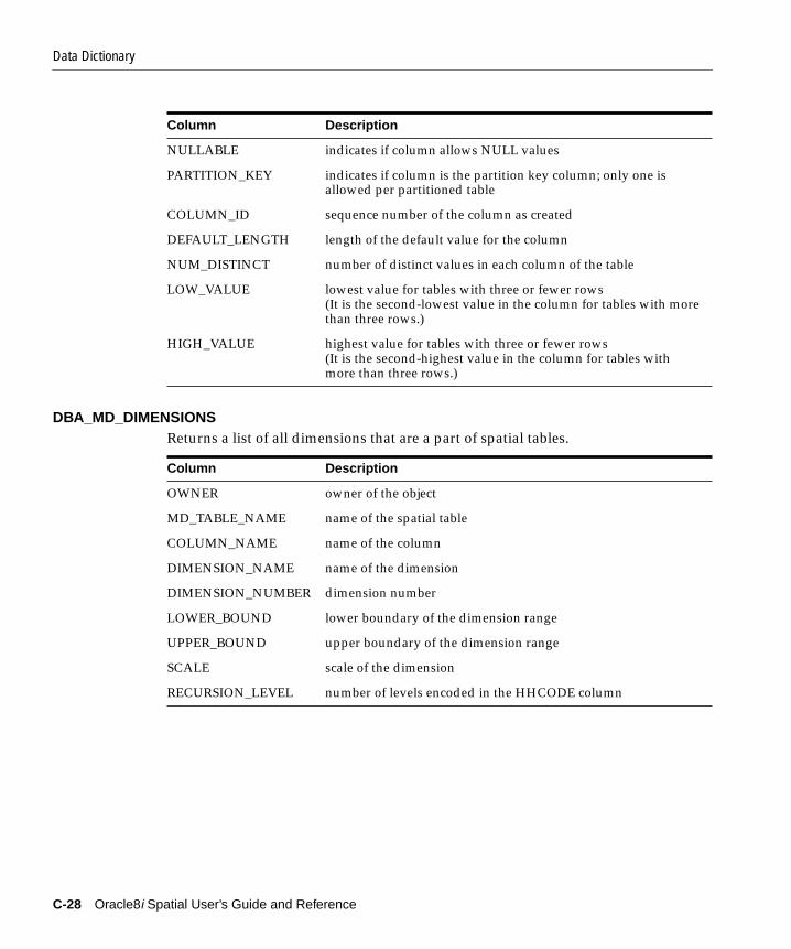
Data Dictionary
DBA_MD_DIMENSIONSReturns a list of all dimensions that are a part of spatial tables.
NULLABLE indicates if column allows NULL values
PARTITION_KEY indicates if column is the partition key column; only one isallowed per partitioned table
COLUMN_ID sequence number of the column as created
DEFAULT_LENGTH length of the default value for the column
NUM_DISTINCT number of distinct values in each column of the table
LOW_VALUE lowest value for tables with three or fewer rows(It is the second-lowest value in the column for tables with morethan three rows.)
HIGH_VALUE highest value for tables with three or fewer rows(It is the second-highest value in the column for tables withmore than three rows.)
Column Description
OWNER owner of the object
MD_TABLE_NAME name of the spatial table
COLUMN_NAME name of the column
DIMENSION_NAME name of the dimension
DIMENSION_NUMBER dimension number
LOWER_BOUND lower boundary of the dimension range
UPPER_BOUND upper boundary of the dimension range
SCALE scale of the dimension
RECURSION_LEVEL number of levels encoded in the HHCODE column
Column Description
C-28 Oracle8i Spatial User’s Guide and Reference

Data Dictionary
DBA_MD_EXCEPTIONSContains information about spatial tables that should be removed (dropped) as aresult of some failed operation, such as a failed load.
DBA_MD_LOADER_ERRORSContains the current status of a file that was loaded into a table using SD*Loader.
DBA_MD_PARTITIONSReturns a list of all the partitioned tables.
Column Description
OWNER owner of the object
NAME object name
OPERATION operation during which the failure occurred
CCHH common code HHCODE
Column Description
OWNER owner of the table where the error occurred
MD_TABLE_NAME spatial table name
FILENAME SLF file name
ROWS_LOADED number of rows loaded before failure
Column Description
OWNER owner of the object
MD_TABLE_NAME name of the spatial table
PARTITION_TABLE_NAME name of the partitioned table
CLASS class of partition: NODE or LEAF
COMMON_LEVEL number of levels of resolution of the common HHCODEcolumn for the partition
COMMON_HHCODE common HHCODE substring for the partition
OFFLINE_STATUS status of partition: ONLINE or OFFLINE
ARCHIVE_DATE date of last archive
Partitioning Legacy Point Data C-29

Data Dictionary
DBA_MD_TABLESReturns a list of all the spatial tables.
DBA_MD_TABLESPACESReturns a list of all tablespaces used by spatial tables.
USER_MD_COLUMNSReturns a list of all the HHCODE columns that are part of tables owned by the user.
Column Description
OWNER owner of the table
MD_TABLE_NAME name of the spatial table
CLASS class of table: PARTITIONED or NON-PARTITIONED
PTAB_SEQ number of last partitioned table created
HIGH_WATER_MARK maximum number of rows that can be inserted into apartitioned table
OFFLINE_PATH complete path name to directory where the table is archived
COUNT_MODE count mode for estimating number of rows in a partition:ESTIMATE or EXACT
Column Description
OWNER owner of the object
MD_TABLE_NAME name of the spatial table
TABLESPACE_NAME name of tablespace
SEQUENCE sequence number
STATUS status of tablespace: ACTIVE or INACTIVE
Column Description
MD_TABLE_NAME name of the spatial table
COLUMN_NAME name of the spatial table
DATA_TYPE data type of the column
DATA_LENGTH length of the column in bytes
C-30 Oracle8i Spatial User’s Guide and Reference

Data Dictionary
USER_MD_DIMENSIONSReturns a list of all dimensions that are part of HHCODE columns owned by theuser.
DATA_PRECISION scale for NUMBER data type, binary precision forFLOAT data type, and NULL for all other data types
DATA_SCALE digits to right of the decimal point in an HHCODE column or anumber
NDIM number of dimensions in the HHCODE column(It is NULL for all other data types.)
MAX_LEVEL maximum number of levels in the column
NULLABLE indicates if column allows NULL values
PARTITION_KEY indicates if column is the partition key column; only oneallowed per partitioned table
COLUMN_ID sequence number of the column as created
DEFAULT_LENGTH length of the default value for the column
NUM_DISTINCT number of distinct values in each column of the table
LOW_VALUE lowest value for tables with three or fewer rows(It is the second-lowest value in the column for tables with morethan three rows.)
HIGH_VALUE highest value for tables with three or fewer rows(It is the second-highest value in the column for tables withmore than three rows.)
Column Description
MD_TABLE_NAME name of the spatial table
COLUMN_NAME name of the column
DIMENSION_NAME name of the dimension
DIMENSION_NUMBER dimension number
LOWER_BOUND lower boundary of dimension range
UPPER_BOUND upper boundary of dimension range
SCALE scale of the dimension
Column Description
Partitioning Legacy Point Data C-31

Data Dictionary
USER_MD_EXCEPTIONSContains information about spatial tables that should be removed (dropped) as aresult of some failed operation, such as a failed load.
USER_MD_LOADER_ERRORSContains the current status of a file that was loaded into a table using SD*Loader.
USER_MD_PARTITIONSReturns a list of all the partitioned tables that are part of spatial tables owned bythe user.
RECURSION_LEVEL number of levels encoded in the HHCODE column
Column Description
NAME object name
OPERATION operation during which the failure occurred
CCHH common code HHCODE
Column Description
MD_TABLE_NAME spatial table name
FILENAME SLF file name
ROWS_LOADED number of rows loaded before failure
Column Description
MD_TABLE_NAME name of the spatial table
PARTITION_TABLE_NAME name of the partition
CLASS class of partition: NODE or LEAF
COMMON_LEVEL number of levels of resolution of the common HHCODEcolumn for the partition
COMMON_HHCODE common HHCODE substring for the partition
OFFLINE_STATUS status of partition: ONLINE or OFFLINE
ARCHIVE_DATE date of last archive
Column Description
C-32 Oracle8i Spatial User’s Guide and Reference

Messages and Codes
USER_MD_TABLES Returns a list of all the spatial tables owned by the user.
USER_MD_TABLESPACES Returns a list of all tablespaces used by spatial tables.
C.7 Messages and CodesMDSQL-00001: partition is OFFLINE
Cause: An MDSQL operation was attempted on a partition that is OFFLINE.
Action: Restore the partition and try the operation again.
MDSQL-00002: PK is out of boundsCause: The partition key for the record being inserted belongs in anotherpartition.
Action: Insert the record into the correct partition. The correct partition can beidentified using the GET_PARTITION_NAME( ) function.
MDSQL-00003: updates that move the PK are not supported
Column Description
MD_TABLE_NAME name of the spatial table
CLASS class of table: PARTITIONED or NON-PARTITIONED
PTAB_SEQ number of last sequence created
HIGH_WATER_MARK maximum number of rows that can be inserted intoa partitioned table
OFFLINE_PATH complete path name to directory where the table is archived
COUNT_MODE count mode for estimating number of rows in a partition:ESTIMATE or EXACT
Column Description
MD_TABLE_NAME name of the spatial table
TABLESPACE_NAME name of tablespace
SEQUENCE sequence number
STATUS status of the tablespace: ACTIVE or INACTIVE
Partitioning Legacy Point Data C-33

Messages and Codes
Cause: The update of the partition key would result in the record belongingto another partition.
Action: Use the MD_DML.MOVE_RECORD( ) procedure to update the parti-tion key and move the record to the correct partition.
C-34 Oracle8i Spatial User’s Guide and Reference

Glossary
area
An extent or region of dimensional space.
attribute
Descriptive information characterizing a geographical feature such as a point, line,or area.
attribute data
Nondimensional data that provides additional descriptive information aboutmultidimensional data, for example a class or feature such as a bridge or a road.
boundary
1. The lower or upper extent of the range of a dimension, expressed by a numericvalue.
2. The line representing the outline of a polygon.
Cartesian coordinate system
A coordinate system in which the location of a point in n-dimensional space isdefined by distances from the point to the reference plane. Distances are measuredparallel to the planes intersecting a given reference plane.
contain
To describe a geometric relationship where one object encompasses another and theinner object does not touch any boundaries of the outer. The outer object containsthe inner object. See also inside.
Glossary-1
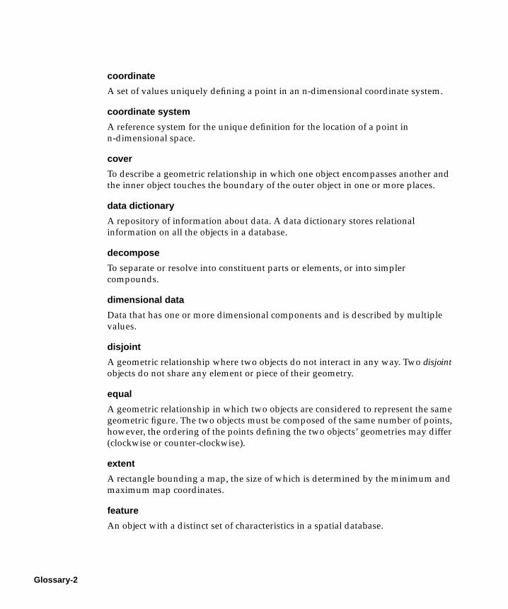
coordinate
A set of values uniquely defining a point in an n-dimensional coordinate system.
coordinate system
A reference system for the unique definition for the location of a point inn-dimensional space.
cover
To describe a geometric relationship in which one object encompasses another andthe inner object touches the boundary of the outer object in one or more places.
data dictionary
A repository of information about data. A data dictionary stores relationalinformation on all the objects in a database.
decompose
To separate or resolve into constituent parts or elements, or into simplercompounds.
dimensional data
Data that has one or more dimensional components and is described by multiplevalues.
disjoint
A geometric relationship where two objects do not interact in any way. Two disjointobjects do not share any element or piece of their geometry.
equal
A geometric relationship in which two objects are considered to represent the samegeometric figure. The two objects must be composed of the same number of points,however, the ordering of the points defining the two objects’ geometries may differ(clockwise or counter-clockwise).
extent
A rectangle bounding a map, the size of which is determined by the minimum andmaximum map coordinates.
feature
An object with a distinct set of characteristics in a spatial database.
Glossary-2

geographical information system
A computerized database management system used for the capture, conversion,storage, retrieval, analysis, and display of spatial data.
geographically referenced data
See spatiotemporal data.
georeferenced data
See spatiotemporal data.
GIS
See geographical information system.
grid
A data structure composed of points located at the nodes of an imaginary grid. Thespacing of the nodes is constant in both the horizontal and vertical directions.
HHCODE
A data type representing the intersection point of multiple dimensions. It encodesthese multiple dimensions into a unique, linear value. The HHCODE data typeswere used for both spatial indexing and partitioned point data in previous releasesof Spatial.
high-water mark
Expressed in number of records and associated with the deprecated Spatialpartitioned table structure, it defines the maximum number of records to store in atable before decomposing another level. The high-water mark determines themaximum size of a partition within the Spatial table. Partitioned tables were analternative to spatial indexing.
hole
A polygon can include subelements that negate sections of its interior. For example,consider a polygon representing a map of a buildable land with an inner polygon(a hole) representing where a lake is located.
homogeneous
Spatial data of one feature type such as points, lines, or regions.
Glossary-3

hyperspatial data
In mathematics, any space comprising more than the three standard x, y, and zdimensions, also referred to as multidimensional data.
index
Identifier that is not part of a database and used to access stored information.
inside
To describe a geometric relationship where one object is surrounded by a largerobject and the inner object does not touch the boundary of the outer. The smallerobject is inside the larger. See also contain.
key
A field in a database used to obtain access to stored information.
keyword
Synonym for reserved word.
latitude
North/South position of a point on the Earth defined as the angle between thenormal to the Earth’s surface at that point and the plane of the equator.
line
A geometric object represented by a series of points, or inferred as existing betweentwo coordinate points.
longitude
East/West position of a point on the Earth defined as the angle between the planeof a reference meridian and the plane of a meridian passing through an arbitrarypoint.
multidimensional data
See hyperspatial data.
partition
1. The spatial table that contains data only for a unique bounded n-dimensionalspace.
2. The process of grouping data into partitions that maintain the dimensionalorganization of the data.
Glossary-4

partition key column
The primary HHCODE column that is used to dimensionally partition the data.One HHCODE data type column must be identified as the partition key for thetable to be registered as partitionable in the Spatial data dictionary. There can beonly one partition key per spatial table. Note that this is only used for thedeprecated partitioned point data model, and not for spatially indexed data.
partitioned table
The spatial logical table structure that contains one or more partitions. Usepartitioned tables only if you are dealing with a very large amount of legacy pointdata (over 50 gigabytes).
polygon
A class of spatial objects having a nonzero area and perimeter, and representing aclosed boundary region of uniform characteristics.
proximity
A measure of inter-object distance.
query
A set of conditions or questions that form the basis for the retrieval of informationfrom a database.
query window
Area within which the retrieval of spatial information and related attributes isperformed.
RDBMS
See Relational Database Management System.
recursion
A process, function, or routine that executes continuously until a specifiedcondition is met.
region
An extent or area of multidimensional space.
Glossary-5

Relational Database Management System (RDBMS)
A computer program designed to store and retrieve shared data. In a relationalsystem, data is stored in tables consisting of one or more rows, each containing thesame set of columns. Oracle8i is an object-relational database management system.Other types of database systems are called hierarchical or network databasesystems.
resolution
The number of subdivision levels of data.
scale
1. The number of digits to the right of the decimal point in a number representingthe level of resolution of an HHCODE.
2. The ratio of the distance on a map, photograph, or image to the correspondingimage on the ground, all expressed in the same units.
SD*Converter
A utility used with previous releases of Spatial Data Option to prepare data forloading into spatial tables. Loading is now accomplished through SQL*Loader.
SLF
See Spatial Load Format.
sort
The operation of arranging a set of items according to a key that determines thesequence and precedence of items.
spatial
A generic term used to reference the mathematical concept of n-dimensional data.
spatial data
Data that is referenced by its location in n-dimensional space. The position ofspatial data is described by multiple values. See also hyperspatial data.
spatial database
A database containing information indexed by location.
spatial data model
A model of how objects are located on a spatial context.
Glossary-6
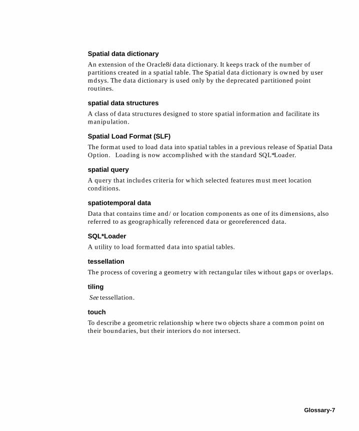
Spatial data dictionary
An extension of the Oracle8i data dictionary. It keeps track of the number ofpartitions created in a spatial table. The Spatial data dictionary is owned by usermdsys. The data dictionary is used only by the deprecated partitioned pointroutines.
spatial data structures
A class of data structures designed to store spatial information and facilitate itsmanipulation.
Spatial Load Format (SLF)
The format used to load data into spatial tables in a previous release of Spatial DataOption. Loading is now accomplished with the standard SQL*Loader.
spatial query
A query that includes criteria for which selected features must meet locationconditions.
spatiotemporal data
Data that contains time and/or location components as one of its dimensions, alsoreferred to as geographically referenced data or georeferenced data.
SQL*Loader
A utility to load formatted data into spatial tables.
tessellation
The process of covering a geometry with rectangular tiles without gaps or overlaps.
tiling
See tessellation.
touch
To describe a geometric relationship where two objects share a common point ontheir boundaries, but their interiors do not intersect.
Glossary-7

Glossary-8

Index
Aadministrative procedures, 13-1ALTER INDEX, 5-2REBUILD, 5-5RENAME TO, 5-8
ALTER_HIGH_WATER_MARK, C-5altering partitions, C-3altpart.sql, C-3ANYINTERACT, 7-4, 15-3arcs, A-13AREA, 7-2area, 7-2, Glossary-1attribute, Glossary-1AVERAGE_MBR, 6-2, 14-2
Bboundary, Glossary-1bounded data, C-21bounded value, C-14buffer area, 7-6BUILD_WINDOW, 16-2BUILD_WINDOW_FIXED, 16-4bulk loading, 3-1, 11-2
CCartesian, Glossary-1circle, 2-5, A-13CLEAN_WINDOW, 16-6CLEANUP_GID, 16-7consistency check, 7-11, 15-5CONTAINS, 7-5, 15-3, Glossary-1
control file, 11-2coordinate, Glossary-2coordinate system, Glossary-2COVEREDBY, 7-5, 15-3COVERS, 7-5, 15-4, Glossary-2cr_spatial_index.sql, A-15CREATE INDEX, 5-9CREATE_WINDOW_LAYER, 16-8creating layer tables, A-16crlayer.sql, A-16customized geometry types, A-13
Ddata, Glossary-2data dictionary, 2-12, C-23, Glossary-7data model, 1-4, A-2DATE data type, C-17, C-22decompose, Glossary-2difference, 7-7dimensional, Glossary-2disjoint, 7-5, 15-4, Glossary-2displaying geometries, A-18, A-19distance, 7-15DROP INDEX, 5-13DROP_PARTITION_INFO, C-6dropping partitions, C-3drppart.sql, C-3dynamic query window, 4-3, 12-4
Eelement, 1-5ENCLOSES, C-15
Index-1

encoding dimensions, C-20EQUAL, 7-5, 15-4, C-15, Glossary-2error messages, xixESTIMATE_INDEX_PERFORMANCE, 6-3, 14-3ESTIMATE_TILING_LEVEL, 6-5, 14-5ESTIMATE_TILING_TIME, 6-7, 14-8extent, 6-8, 14-9, Glossary-2EXTENT_OF, 6-8, 14-9extracting a dimension, C-19
Ffeature, Glossary-2filter, 12-6fixed indexing, 1-9fixed-size tiles, 3-10, 11-7, 13-5, 13-14
Ggeocoding, A-16Geographical Information System, Glossary-3geometric primitive, 1-3geometry types, 1-3
custom, A-13object-relational, 2-2relational, 10-3
georeferenced, Glossary-3GIS, 1-2, Glossary-3grants, C-4, C-9grid, Glossary-3
HHHCODE, Glossary-3high water mark, C-5, Glossary-3HISTOGRAM_ANALYSIS, 6-9, 14-10hole in a polygon, Glossary-3homogeneous, Glossary-3hybrid indexing, 1-14hyperspatial, Glossary-4
Iindex, 13-3, 13-5, 13-12, 13-14, Glossary-4index creation, 3-9, 11-6
in parallel, A-14inserting spatial data, 11-4INSIDE, 7-5, 15-4, C-15interaction, 7-4, 15-3interMedia Locator, A-16intersection, 7-8
Kkey, Glossary-4keyword, Glossary-4
Llatitude, Glossary-4layer, 1-6, A-16
validating, 7-13LENGTH, 7-3line, 2-5, Glossary-4
length, 7-3line data, 1-5loading process, 3-1, 11-2
in parallel, A-14location, 1-2longitude, Glossary-4
Mmigration
OGIS, 8-5, 8-6to Oracle7, 8-2to Oracle8, 8-3
minimum bounding rectangle, 6-2, 6-8, 14-2, 14-9MIX_INFO, 6-11, 14-12
Oobject-relational model
schema, 2-1operators
SDO_FILTER, 9-2SDO_RELATE, 9-4SDO_WITHIN_DISTANCE, 9-7
OUTSIDE, C-15OVERLAP, C-15
Index-2
OVERLAPBDYDISJOINT, 7-5, 15-4OVERLAPBDYINTERSECT, 7-5, 15-4
Pparallel load, A-14partition, C-7, Glossary-4, Glossary-5partition key, C-1partitioned table, C-1, C-3, C-6, C-7, C-10,
Glossary-5partitioned tables, 1-20, A-13plotting tiles, A-4PL/SQL, C-13point data, 1-5, 13-8, A-8polygon, 2-5, Glossary-5
area of, 7-2polygon data, 1-5POPULATE_INDEX, 13-3POPULATE_INDEX_FIXED, 13-5POPULATE_INDEX_FIXED_POINTS, 13-8primary filter, 12-6primitive, 1-3PROPAGATE_GRANTS, C-9proximity, Glossary-5
Qquery, 1-6, Glossary-5query window, 4-3, 12-4, Glossary-5
RRDBMS, Glossary-5, Glossary-6rectangle, 2-5recursion, Glossary-5region, Glossary-5REGISTER_PARTITION_INFO, C-10RELATE, 7-4, 15-2relational model
schema, 10-1REPARTITION, C-11resolution, Glossary-6
Ssample program, A-18, A-19scale, Glossary-6schema, 10-1
object-relational model, 2-1relational model, 10-1
SD*Converter, Glossary-6SD*Loader, Glossary-7SDO_BUFFER, 7-6SDO_BVALUETODIM, C-14SDO_CODE_SIZE, 13-10SDO_COMPARE, C-15SDO_DATETODIM, C-17SDO_DECODE, C-19SDO_ENCODE, C-20SDO_FILTER operator, 9-2SDO_POLY_DIFFERENCE, 7-7SDO_POLY_INTERSECTION, 7-8SDO_POLY_UNION, 7-9SDO_POLY_XOR, 7-10SDO_RELATE operator, 9-4SDO_TO_BVALUE, C-21SDO_TO_DATE, C-22SDO_VERSION, 13-11SDO_WITHIN_DISTANCE operator, 9-7sdogrant.sql, C-4secondary filter, 12-7server partitioning, C-1SLF, Glossary-7sort, Glossary-6spatial data model, Glossary-6spatial data structures, Glossary-7
object-relational model, 2-1relational model, 10-1
spatial database, Glossary-6sizing, A-3
spatial index, 3-9, 11-6, 13-12, 13-14performance, 6-3, 14-3
spatial indexingfixed, 1-9hybrid, 1-14
spatial join, 4-8, 12-8, A-10Spatial Load Format, Glossary-7spatial query, 4-3, 12-4, Glossary-7
Index-3

spatiotemporal, Glossary-7SQL script, A-15, C-3SQL*Loader, 3-1, 11-2
Ttable partitioning, 1-20, C-1tessellation, 1-9, 11-6, 13-3, 13-5, 13-12, 13-14,
Glossary-7tile, 1-8, 4-1, 12-1tiling, 6-5, 13-14, 14-5, A-2, Glossary-7TOUCH, 7-5, 15-4, Glossary-7transactional insert, 3-3, 11-4two-tier query, 1-6, 4-1, 12-1
Uunion, 7-9UPDATE_INDEX, 13-12UPDATE_INDEX_FIXED, 13-14
VVALIDATE_GEOMETRY, 7-11, 15-5VALIDATE_LAYER, 7-13VERIFY_LAYER, 13-16VERIFY_PARTITIONS, C-12visualizing geometries, A-18, A-19visualizing tiles, A-4, A-19
WWITHIN_DISTANCE, 7-15
Index-4