orbital welding facts - fronius
TRANSCRIPT

Orbital welding facts
V02 2010

Original edition, Polysoude Nantes Frankreich SAS
Photos, plans and drawings are used as help to understanding and are thus not contractual. All rights reserved. No total or partial reproduction of this work can made, under any format or by any means, electronic or mechanical, including photocopy, recording or computer techniques, without the written authorization of the publisher.
Published by Fronius International GmbH
3
C O N T E N T S
1. Preface 5
2. What is orbital welding? 5
3. Recapitulation of the TIG (GTAW) process 5
4. Reasons to select orbital welding 11
5. Industries which apply the orbital TIG
welding process successfully 12
6. Specificities of the orbital weld process 14
7. Hardware Components of Orbital Welding Equipment 15
8. Programmable system controllers 16
9. Orbital welding heads 18
10. Wire feeder units 21
11. Functionalities of the orbital welding equipment 21
12. Weld cycle programming 28
13. Real time data recording 31
14. Tube to Tube welding 32
15. Tube to Tube or Pipe to Pipe orbital welding with filler wire 38
16. Orbital tube to tube sheet welding 43
17. Conclusion 50

4

5
1. Preface
Among industrial joining processes, orbital
TIG welding has meanwhile become a well-
established method, although a considera-
ble lack of information about the various
possibilities of this challenging technique
still remains in public. Aerospace industry,
aviation, high speed trains, nuclear indus-
try, pharmaceutical industry, food industry,
tiny microelectronic devices - just to name a
few of the most exciting applications - rely
on orbital welding, but the equipment to
ensure our daily supply with electric current,
oil and gas also depends on orbital welding
techniques.
In this booklet basic information is provided
about the orbital weld process and the related
equipment: technical approach, advantages,
common and special applications, but also
restrictions and limits. To give an idea how
reality looks like, the text is illustrated by
numerous application examples.
Tables and designs shall help engineers and
welding experts, as well as project managers,
to get quick answers whether orbital welding
could offer solutions corresponding to
their needs. To get specific answers to your
questions, consult the customer service
team.
2. What is orbital welding?
Whenever high quality results are required,
orbital welding is the first choice for the joi-
ning of tubes. The welding torch - in most
cases, the TIG-welding (Tungsten Inert Gas)
process is used - travels around the tubes to
be joined, guided by a mechanical system.
The name orbital welding comes from the cir-
cular movement of the welding tool around
the workpiece.
Generally, orbital welding technique covers
two main fields of application:
�� Tube to tube / pipe to pipe joining.
�� Tube to tube sheet welding.
In the first group, all kinds of tube joining
are included: butt welding and welding of
flanges, bends, T-fittings and valves, i.e. the
entire tubing and piping requirements.
The second group concerns the manufac-
turing of boilers and heat-exchangers and
comprises the different welding tasks related
to tube to tube sheet welding operations.
3. Recapitulation of the TIG (GTAW) process
An electric arc is maintained between the
non-consumable tungsten electrode and the
workpiece. The electrode supports the heat
of the arc; the metal of the workpiece melts
and forms the weld puddle.
The molten metal of the workpiece and the
electrode must be protected against oxy-
gen in the atmosphere; an inert gas such as
argon serves as shielding gas.
If the addition of filler metal becomes
necessary, filler wire can be fed to the weld
puddle, where it melts due to the energy
delivered by the electric arc.

6
3.2. Types of weld currents
Two kinds of current are applied in the TIG
welding technique:
�� Direct Current (DC) is most frequently
used to weld nearly all types of materials.
�� Alternating Current (AC) is preferred to
weld aluminium and aluminium alloys.
If DC is used, the electrode is connected
as cathode to the negative terminal of the
power source; this configuration is named
DCEN or Direct Current Electrode Negative. In
this case, the electrons of the electric arc flow
from the electrode with negative polarity to
the workpiece with positive polarity. Up to
70 % of the released energy is considered to
heat up the workpiece, which means an effi-
ciency of 0.7 (useful energy/released energy).
The configuration DCEP or Direct Current
Electrode Positive is not used in the TIG
process except of some very special appli-
cations in aluminium welding. In this mode
however, most of the heat is transmitted to
the tungsten electrode, so already at low
weld current intensities, very large electrode
diameters, compared to TIG DCEN, become
necessary to carry off the heat.
In the AC mode, the electrode is switched
periodically between positive and negative
polarity. During the time of positive polarity
the tungsten electrode acts as the anode,
due to the cleaning effect produced, the
oxide layer on the surface of the workpiece
will be destroyed. During the time of nega-
tive polarity the tungsten electrode acts as
cathode, the heat necessary to melt the alu-
minium is applied to the workpiece; in this
phase the electrode can then cool down.
3.1. Advantages/Inconveniences of the TIG (GTAW) process
1 - Nearly all metals can be joined.
2 - Different kinds of steel, stainless steel
included, can be welded as well as refractory
or wear-resistant nickel alloys, aluminium,
copper, gold, magnesium, tantalum, tita-
nium, zirconium, and their alloys; even brass
and bronze can be welded in certain cases; if
filler wire is applied, workpieces consisting of
dissimilar alloys or batches can also be joined
together.
3 - All welding positions are possible.
4 - The process is very stable and reliable;
the occurrence of weld defects can be redu-
ced to less than 1 %.
5 - No slag or fumes are developed during
welding.
6 - The affecting weld parameters can be
adjusted in a wide range and mostly inde-
pendent one of each other.
7 - TIG welding can be carried out with or
without filler wire.
8 - The arc voltage, which is directly rela-
ted to the arc length, and the weld current
intensity offer a wide range of variations
and can be controlled automatically.
3.1.1. Advantages
3.1.2. Inconveniences
1 - Compared to other arc welding proc-
esses, the deposition rate of the TIG process
is relatively low.
2 - Time-intensive and costly development is
necessary to determine the weld procedures
and the exact values of weld parameters
which are necessary to control the process.
3 - The welding equipment is sophisticated;
it requires much more capital investment
cost than gear for manual welding.
7
3.3. Tungsten electrodes
3.3.1. Types of electrodes
Tungsten is a highly refractory metal with a
melting point of 3,410 °C. It withstands the
heat of the electric arc and keeps its hardness
even if it becomes red hot. In the past, tho-
riated tungsten electrodes have been widely
used for TIG welding, but as thorium is a low-
level radioactive element, special grinding
equipment is required to ensure a safe dispo-
sal of the grinding particles.
Today, different alloyed tungsten electrodes
are preferred, e.g. Ceriated or Lanthanated
types, which are free of any radioactivity. In
addition, their performance is comparable to
that of thoriated tungsten electrodes.
3.4. Filler metals
1 - The welding seam must be reinforced.
2 - If carbon steel or mild steel have to be
welded.
3 - In case of a preparation of the tube ends,
for example a J or V preparation.
4 - To prevent metallurgical failure if the
tubes to be welded are made of dissimilar
metals or alloys.
A well-known example is the welded connec-
tion between carbon steel and Stainless
Steel 316, where a filler wire made of Stainless
Steel 309 or nickel base alloy Inconel 82® is
added.
5 - If the alloys change their composition or
structure during welding.
Alloying elements can evaporate during the
weld process or form a new compound. For
example, chromium carbide is developed if
chromium combines with carbon. The resul-
ting lack of metallic chromium can cause an
unwanted loss of corrosion resistance at the
heat affected zone.
The application of filler wire may become necessary under the following conditions:
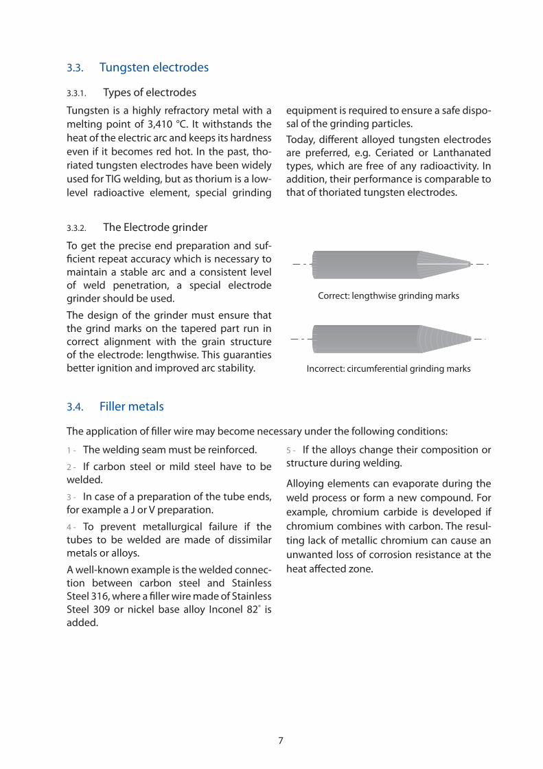
3.3.2. The Electrode grinder
To get the precise end preparation and suf-
ficient repeat accuracy which is necessary to
maintain a stable arc and a consistent level
of weld penetration, a special electrode
grinder should be used.
The design of the grinder must ensure that
the grind marks on the tapered part run in
correct alignment with the grain structure
of the electrode: lengthwise. This guaranties
better ignition and improved arc stability.
Correct: lengthwise grinding marks
Incorrect: circumferential grinding marks
8
3.5. Gases
3.5.1. Welding gases
Argon is commonly used as shielding gas
in the TIG process. It provides good arc stri-
king characteristics and excellent arc stabi-
lity even at low amperages, the energy of
the arc is confined to a narrow area. Argon
is also compatible with all types of base
materials.
Shielding gas for standard TIG welding
purposes should have a purity of 4.5, i.e. a
purity level of 99.995 %. Metals which are
classified as delicate to weld for example;
titanium, tantalum, zirconium and their alloys
require a purity of at least 4.8, which means a
purity level of 99.998 %.
To increase the weld energy, 2 % to 5 %
hydrogen can be added to the argon. Besides
a higher energy input of 10 % to 20 % resul-
ting in a better penetration and faster wel-
ding speeds, argon / hydrogen mixtures have
reducing properties helping to protect the
molten metal against the influence of oxygen
from the surrounding atmosphere. However,
mild and carbon steels absorb hydrogen
with the possible result of porosity and cold
cracking, so the use of hydrogen containing
gas mixtures is not recommended; for the
welding of aluminium and titanium they are
strictly forbidden.
The weld energy can also be increased by
argon/helium mixtures with helium contents
of 20 %, 50 % or 70 % or even pure helium.
Helium has no detrimental effects on tita-
nium, so it is used especially to weld the
pure metal or titanium containing alloys.
Mixtures of argon, helium and nitrogen
are used to weld Duplex and Super Duplex
steels.
Unlike argon, helium is a good heat conduc-
tor. The arc voltage under helium is much
higher than under argon, so the energy
content of the arc is strongly increased. The
arc column is wider and allows deeper pene-
tration. Helium is applied for the welding
of metals with high heat conductivity like
copper, aluminium and light metal alloys.
As helium is a lightweight gas, compared to
argon its flow rate for identical gas coverage
must be increased two to three times.
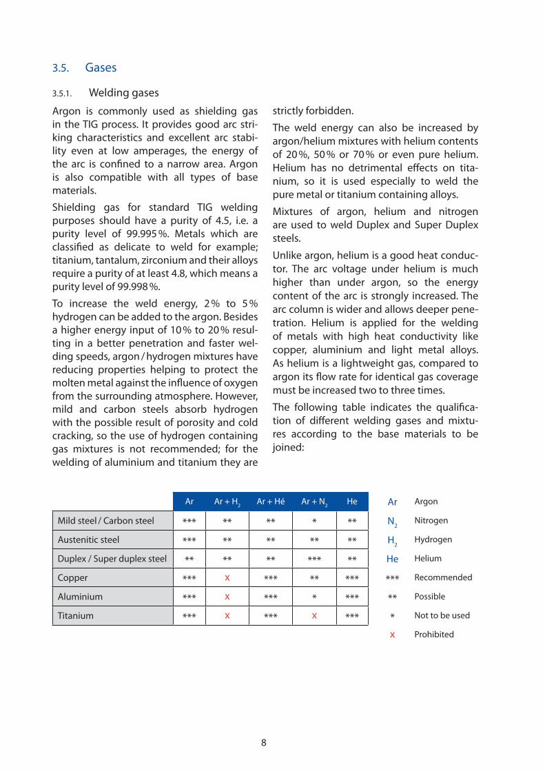
The following table indicates the qualifica-
tion of different welding gases and mixtu-
res according to the base materials to be
joined:
Ar Ar + H2
Ar + Hé Ar + N2
He Ar Argon
Mild steel / Carbon steel *** ** ** * ** N2
Nitrogen
Austenitic steel *** ** ** ** ** H2
Hydrogen
Duplex / Super duplex steel ** ** ** *** ** He Helium
Copper *** x *** ** *** *** Recommended
Aluminium *** x *** * *** ** Possible
Titanium *** x *** x *** * Not to be used
x Prohibited

9
3.5.2. Backing gases
Most applications of orbital welding require
an outstanding quality to the inside of the
root, as this is the part of the weld which
will be in direct contact with the transpor-
ted medium. To avoid any risk of oxidation,
before, during and after the welding opera-
tion the hot metal at the inside of the tube
must be prevented from coming in contact
with oxygen in the atmosphere. Depending
on the material to be welded, reducing com-
ponents like N2 or H
2 are added to the bac-
king gas. The most typical backing gases and
mixtures applicable for the different base
metals are:
Ar N2
Ar + H2 ou N
2 + H
2 Ar Argon
Mild steel / Carbon steel *** *** * N2
Nitrogen
Austenitic steel *** *** *** H2
Hydrogen
Duplex / Super duplex steel ** *** ** *** Recommended
Copper *** ** ** ** Possible
Aluminium *** * x * Not to be used
Titanium *** x x x Prohibited
3.6. Weld energy
3.6.1. The Influence of heat input
The heat input cannot be measured, but only
calculated; its quantity is used e.g. to com-
pare different weld procedures for a given
weld process. The heat input influences the
cooling rate and the HAZ (Heat Affected
Zone) of the weld. A lower heat input allows
us to obtain faster cooling rates and a smaller
HAZ. With fast cooling rates, microstructure
modifications of the base metal like grain
growth or precipitations can be minimised,
avoiding the loss of too much mechanical
strength or corrosion-resistance. For many
materials, e.g. sophisticated heat-treated and
stainless steels, the heat input is limited by
the specifications of the manufacturer.
In manual welding, to obtain a particular heat
input, the welder must keep the arc length
continuously at a specified level, by that the
arc voltage remains constant at the desired
weld current intensity. But additionally, as the
heat input is influenced significantly by the
travel speed, the manual welder must finish
the weld within a fixed period of time. Only
well-trained welding staff with excellent skills
is able to meet these requirements.
In automatic Gas Tungsten Arc Welding, the
process parameters arc voltage and weld cur-
rent intensity, as well as travel speed and wire
feed rates are controlled and kept constant
by the microelectronic devices functioning
within the power source, so the demand to
respect a specified heat input does not cause
any problems.
10
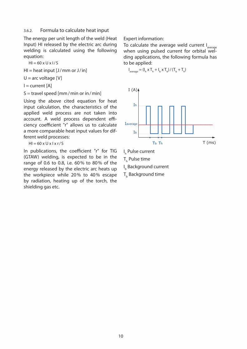
3.6.2. Formula to calculate heat input
The energy per unit length of the weld (Heat
Input) HI released by the electric arc during
welding is calculated using the following
equation:
HI = 60 x U x I / S
HI = heat input [J / mm or J / in]
U = arc voltage [V]
I = current [A]
S = travel speed [mm / min or in / min]
Using the above cited equation for heat
input calculation, the characteristics of the
applied weld process are not taken into
account. A weld process dependent effi-
ciency coefficient "r" allows us to calculate
a more comparable heat input values for dif-
ferent weld processes:
HI = 60 x U x I x r / S
In publications, the coefficient "r" for TIG
(GTAW) welding, is expected to be in the
range of 0.6 to 0.8, i.e. 60 % to 80 % of the
energy released by the electric arc heats up
the workpiece while 20 % to 40 % escape
by radiation, heating up of the torch, the
shielding gas etc.
Ih
Ib
Iaverage
Tb Th
I (A)
T (ms)
Ih Pulse current
Th Pulse time
Ib Background current
Tb Background time
Expert information:
To calculate the average weld current Iaverage
when using pulsed current for orbital wel-
ding applications, the following formula has
to be applied:
Iaverage
= (Ih x T
h + I
b x T
b) / (T
b + T
h)

11
4. Reasons to select orbital welding
The decision for the use of mechanised or automatic orbital TIG welding can be taken for dif-
ferent reasons: economic, technical, organisational, and others may be more or less important
or even become the decisive factor. The orbital welding process offers a large range of benefits
which qualifies it for industrial applications. The major advantages are:
4.1. Increased productivity compared to manual welding
Compared to manual TIG welding, the
mechanised or automatic process leads to
enhanced productivity. Repetitive work in
the shop or complicated assembly jobs on
site - orbital welding equipment guarantees
that approved weld sequences are reliably
repeated, hence time-consuming repair work
will be reduced to a minimum.
4.2. Consistent excellent weld quality
Generally, the weld quality obtained by
mechanised equipment is superior to that
of manual welding. Once an adequate weld
program has been developed, the weld
cycle can be repeated as often as necessary,
without deviations and virtually without
weld defects.
4.3. Required skill levels of the operators
Certified welders are difficult to find and well
remunerated. However, after appropriate
training, skilled mechanics are able to ope-
rate orbital welding equipment perfectly and
get excellent results. By using this equipment
expenditure on personnel can be reduced.
4.4. Environment
Orbital welding can be executed even under
harsh environmental conditions. Restricted
space or access, lack of visibility, presence
of radiation; once the weld head is positio-
ned properly, the weld can be accomplished
without problems from a safe distance; often
supported by a video transmission.
4.5. Traceability – Quality Control
Modern orbital welding equipment is desig-
ned for real-time monitoring of the affecting
weld parameters; a complete weld protocol
can be generated and stored or output as a
printed document. Sophisticated data acqui-
sition systems operate in the background,
if they are connected directly to a superior
quality management system; automatic data
transfer takes place without any interrup-
tions to the weld procedure.

12
5. Industries which apply the orbital TIG welding process
successfully
5.1. Aircraft industry
In the aircraft industry, which was the first
one to recognize the importance of orbi-
tal welding for their purposes, more than
1,500 welds are necessary to complete the
high pressure system of one single plane.
Manual welding of the small, thin-walled
tubes is extremely difficult; finally the requi-
red consistent joint quality cannot be gua-
ranteed. The only solution is to establish
welding procedures using orbital equipment.
In this way, the parameter values are reliably
controlled by the equipment and the final
welds meet the same quality level as the qua-
lified test welds.
5.2. Food, diary and beverage industries
The food, diary and beverage industries
need tube and pipe systems meeting deli-
cate hygienic requirements. Full penetration
of the welded joints is necessary; any pit,
pore, crevice, crack or undercut can become
a dead spot where the medium is trapped
and pathogenic bacteria growth, (Listeria
etc.), can occur. Smooth surfaces everywhere
inside the tubes enable successful cleaning
and complete sterilisation of the system. The
requested surface quality can only be ensu-
red if orbital TIG equipment is used to weld
these critical joints. Therefore, most stan-
dards and specifications oblige nowadays
the manufacturers of hygienic installations to
apply this process.
5.3. Pharmaceutical and biotechnology industries
Plants in pharmaceutical industries must be
equipped with pipe systems for the trans-
port and the treatment of the product and
for the safe supply of clean steam and injec-
tion water. For injection water and its deri-
vatives that are intended for injection into
the human body, the purity requirements
are particularly high. Any traces of corrosion
are absolutely forbidden, the corrosion resis-
tance of these welds must not be undermi-
ned, especially not by partial overheating
of the base material. Joints made by orbital
welding qualify for extended corrosion resis-
tance. Additionally, to avoid any subsequent
oxidation or corrosion, their smooth surface
can be passivated.

13
5.4. Fabrication of semi-conductor devices
For the fabrication of semi-conductor
devices, electro-polished stainless steel tubes
are installed as process gas lines, mostly
with an OD of 6.3 mm and a wall thickness
of 0.9 mm. The ultra-pure process gas must
pass the tubes without picking up moisture,
oxygen, particles or other contaminants. The
acceptance criteria for these installations
are very stringent: uniform welds with small
weld beads to minimize the weld surface in
the tubes, full penetration on the ID, absence
of discoloration, etc. Only experienced ope-
rators working with reliable orbital welding
equipment are able to perform this task,
often even under adverse conditions on site.
5.5. Chemical industries
A considerable part of plant equipment
for chemical industries are manufactured
and installed by means of orbital welding.
Chemical apparatuses are comprise of tubes,
heat exchangers and converters which are
made of corrosion-resistant or refractory
metals or alloys of titanium, zirconium, nickel,
chrome etc.; not to forget the whole range of
different stainless steel types. As the service
life of the installations depend directly on
the quality level of the welded joints, strict
control and traceability of the weld process
are required by customers, inspection bodies
and standards authorities. For the assembly
of one heat exchanger, hundreds or even
several thousand faultless welds have to be
carried out, so here orbital welding becomes
a must to ensure the expected results.
5.6. Power generation
For the safety of power stations the whole
range of orbital joining techniques are
applied: tubes with small diameters for sen-
sing and control purposes must be connec-
ted, heat exchangers and other components
are manufactured using orbital tube to tube
sheet welding, and thick-walled tubes for
operation under high pressure and tempe-
rature must be assembled on site. The wel-
ding procedures and the weld quality are
generally under constant surveillance of the
respective authorities and external organisa-
tions, the required complete documentation
and traceability is ensured by the provision of
orbital equipment with online data acquisi-
tion systems.
14
6. Specificities of the orbital weld process
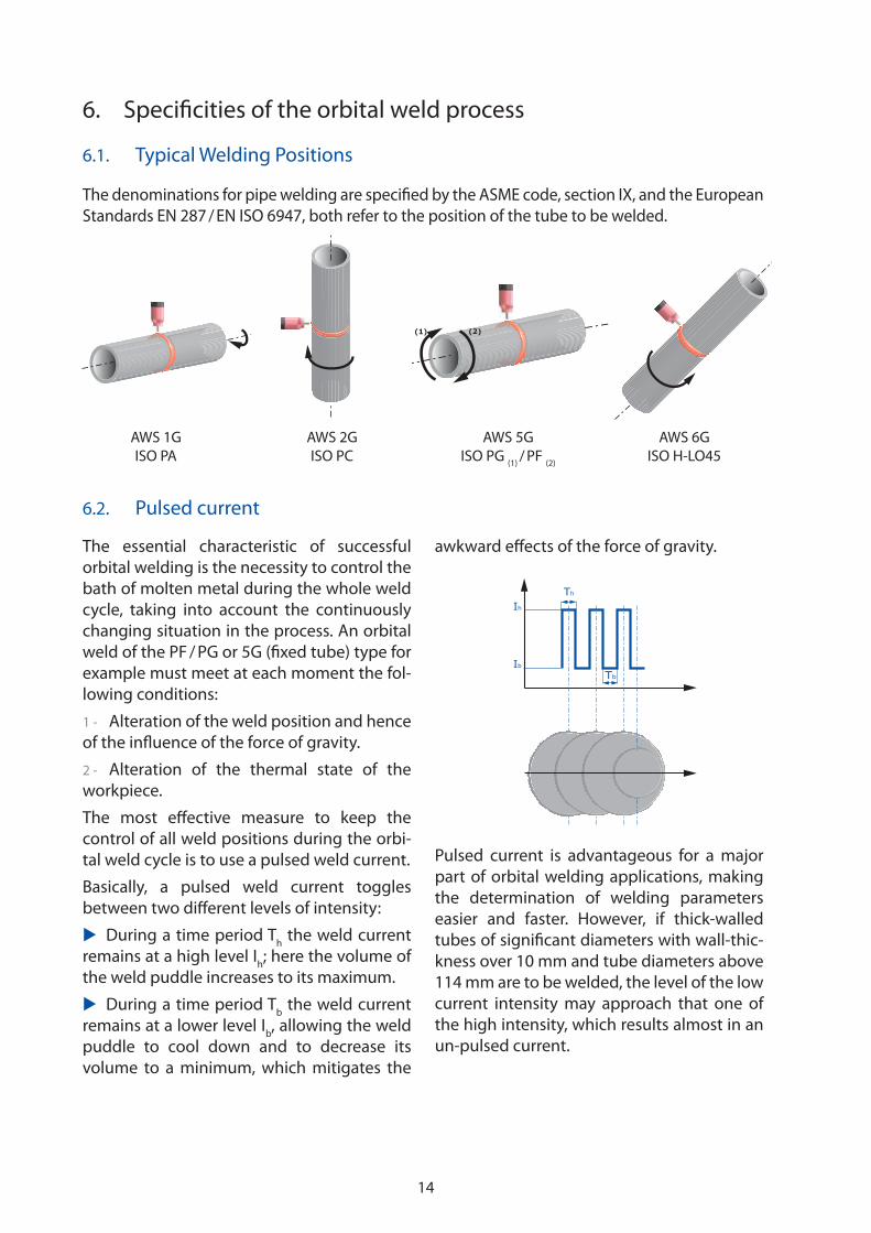
6.1. Typical Welding Positions
The denominations for pipe welding are specified by the ASME code, section IX, and the European
Standards EN 287 / EN ISO 6947, both refer to the position of the tube to be welded.
6.2. Pulsed current
The essential characteristic of successful
orbital welding is the necessity to control the
bath of molten metal during the whole weld
cycle, taking into account the continuously
changing situation in the process. An orbital
weld of the PF / PG or 5G (fixed tube) type for
example must meet at each moment the fol-
lowing conditions:
1 - Alteration of the weld position and hence
of the influence of the force of gravity.
2 - Alteration of the thermal state of the
workpiece.
The most effective measure to keep the
control of all weld positions during the orbi-
tal weld cycle is to use a pulsed weld current.
Basically, a pulsed weld current toggles
between two different levels of intensity:
�� During a time period Th the weld current
remains at a high level Ih; here the volume of
the weld puddle increases to its maximum.
�� During a time period Tb the weld current
remains at a lower level Ib, allowing the weld
puddle to cool down and to decrease its
volume to a minimum, which mitigates the
awkward effects of the force of gravity.
Ih
Ib
Tb
Th
Pulsed current is advantageous for a major
part of orbital welding applications, making
the determination of welding parameters
easier and faster. However, if thick-walled
tubes of significant diameters with wall-thic-
kness over 10 mm and tube diameters above
114 mm are to be welded, the level of the low
current intensity may approach that one of
the high intensity, which results almost in an
un-pulsed current.
(1) (2)
AWS 1G
ISO PA
AWS 2G
ISO PC
AWS 5G
ISO PG (1)
/ PF (2)
AWS 6G
ISO H-LO45
15
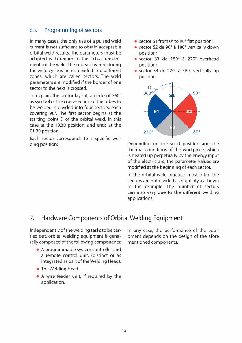
6.3. Programming of sectors
In many cases, the only use of a pulsed weld
current is not sufficient to obtain acceptable
orbital weld results. The parameters must be
adapted with regard to the actual require-
ments of the weld. The course covered during
the weld cycle is hence divided into different
zones, which are called sectors. The weld
parameters are modified if the border of one
sector to the next is crossed.
To explain the sector layout, a circle of 360°
as symbol of the cross-section of the tubes to
be welded is divided into four sectors, each
covering 90°. The first sector begins at the
starting point D of the orbital weld, in this
case at the 10.30 position, and ends at the
01.30 position.
Each sector corresponds to a specific wel-
ding position:
�� sector S1 from 0° to 90° flat position;
�� sector S2 de 90° à 180° vertically down
position;
�� sector S3 de 180° à 270° overhead
position;
�� sector S4 de 270° à 360° vertically up
position.
S4
S3
S2
S10°
360°
270° 180°
90°D
Depending on the weld position and the
thermal conditions of the workpiece, which
is heated up perpetually by the energy input
of the electric arc, the parameter values are
modified at the beginning of each sector.
In the orbital weld practice, most often the
sectors are not divided as regularly as shown
in the example. The number of sectors
can also vary due to the different welding
applications.
7. Hardware Components of Orbital Welding Equipment
Independently of the welding tasks to be car-
ried out, orbital welding equipment is gene-
rally composed of the following components:
�� A programmable system controller and
a remote control unit, (distinct or as
integrated as part of the Welding Head).
�� The Welding Head.
�� A wire feeder unit, if required by the
application.
In any case, the performance of the equi-
pment depends on the design of the afore
mentioned components.
16
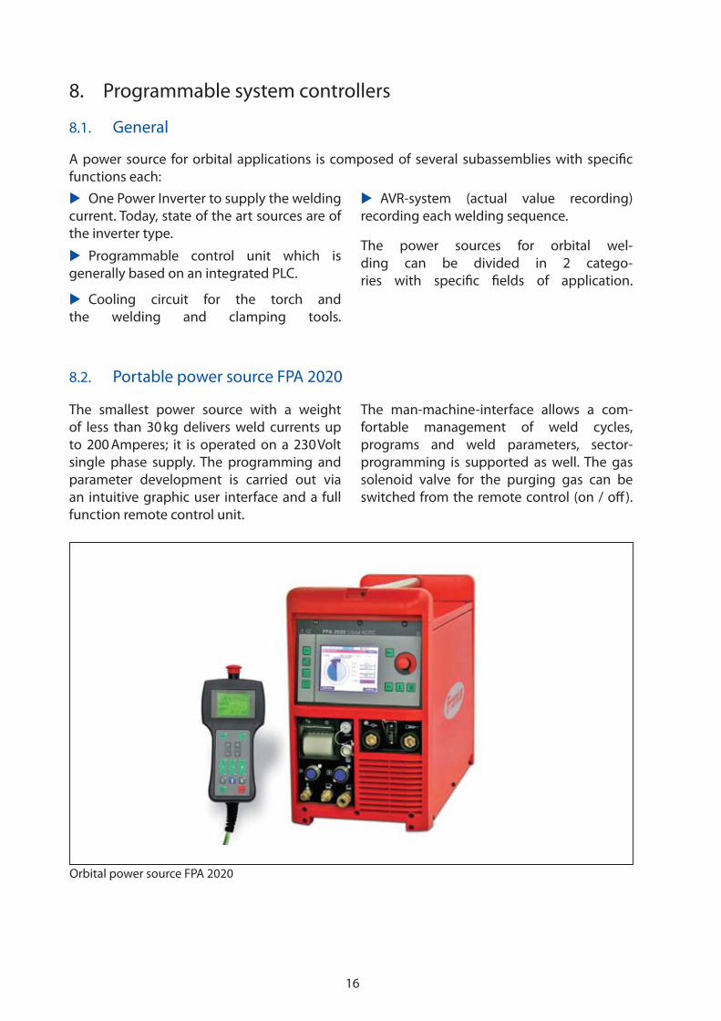
8.2. Portable power source FPA 2020
The smallest power source with a weight
of less than 30 kg delivers weld currents up
to 200 Amperes; it is operated on a 230 Volt
single phase supply. The programming and
parameter development is carried out via
an intuitive graphic user interface and a full
function remote control unit.
The man-machine-interface allows a com-
fortable management of weld cycles,
programs and weld parameters, sector-
programming is supported as well. The gas
solenoid valve for the purging gas can be
switched from the remote control (on / off).
8. Programmable system controllers
8.1. General
�� One Power Inverter to supply the welding
current. Today, state of the art sources are of
the inverter type.
�� Programmable control unit which is
generally based on an integrated PLC.
�� Cooling circuit for the torch and
the welding and clamping tools.
�� AVR-system (actual value recording)
recording each welding sequence.
The power sources for orbital wel-
ding can be divided in 2 catego-
ries with specific fields of application.
A power source for orbital applications is composed of several subassemblies with specific
functions each:
Orbital power source FPA 2020

17
The FPA 2020 is equipped to handle up to four
axes of control, i.e. four devices can be pro-
grammed and controlled: the shielding gas
flow, the weld current intensities and pulse
rates, the travel speed of the welding head,
and wire feeding operations. A closed loop
Cooling System is present to operate water-
cooled orbital Weld Heads and Welding Tools
and is integrated as part of the machine.
Furthermore the FPA 2020 allows us to find
matching weld programs, (if the user speci-
fies basic information about size and mate-
rial of the tubes to be joined), using a touch
screen. The system consults its in-built data-
base to find similar applications or suggests
weld parameters determined by progressive
calculations.
Orbital system controller FPA 2030 with power source
8.3. System controller FPA 2030 with power source
Medium-sized power sources for orbital wel-
ding are too heavy to be carried; they are
mounted on a carriage to keep them mobile.
These power sources are for connection to
three-phase 400 Volt outlets or feature a
multi-voltage input, they generate welding
currents up to 500 Amperes. For the dialog
with the operator, the power sources are
equipped with a convenient man-machine-
interface and a full function remote control
unit.
Medium-sized power sources are designed to
handle up to six axes, which can be program-
med and controlled. Usually these axes are
attributed to the shielding gas flow, the weld
current intensities and pulse rates, the tra-
vel speed of the welding head, the wire fee-
ding operations, and Arc Voltage Control &
Oscillation. The purging gas can be switched
on / off from the remote control as well.

18
Open welding heads were conceived as a tool
for orbital TIG welding with or without filler
wire. The diameters of the tubes to be welded
cover a range from 8 mm up to 275 mm (ANSI
5/16" to 11").
Open welding heads of the U-type are
equipped with a TIG-torch with gas diffuser.
Sufficient gas protection is achieved only at a
zone around the torch which is covered by the
shielding gas streaming out of the gas lens.
During the welding process, the arc can be
watched and controlled directly by the ope-
rator. The asymmetrical design of the open
heads allows welding to be carried out at a
very short distance to a wall or a bend.
The positioning of the welding torch can be
carried out manually or by means of motorized
slides (Arc Voltage Control and oscillation).
9.1.2. Open welding heads of the U type
Open welding head MU
9. Orbital welding heads
9.1. Tube to tube welding heads
Closed chamber welding heads are especially
designed for autogenous welding of tubes
without filler wire; their different sizes cover
a range of diameters between 1.6 mm and
168 mm (ANSI 1/16" to 6"). Besides austenitic
stainless steel, metals susceptible to oxidation
like titanium or zirconium and their alloys can
be welded with excellent results. Depending
on the application, one or two pairs of clam-
ping shells or TCIs (Tube Clamping Inserts) are
needed to fix the closed chamber head on to
the tubes to be welded.Closed chamber welding head MW
9.1.1. Closed chamber welding heads
19
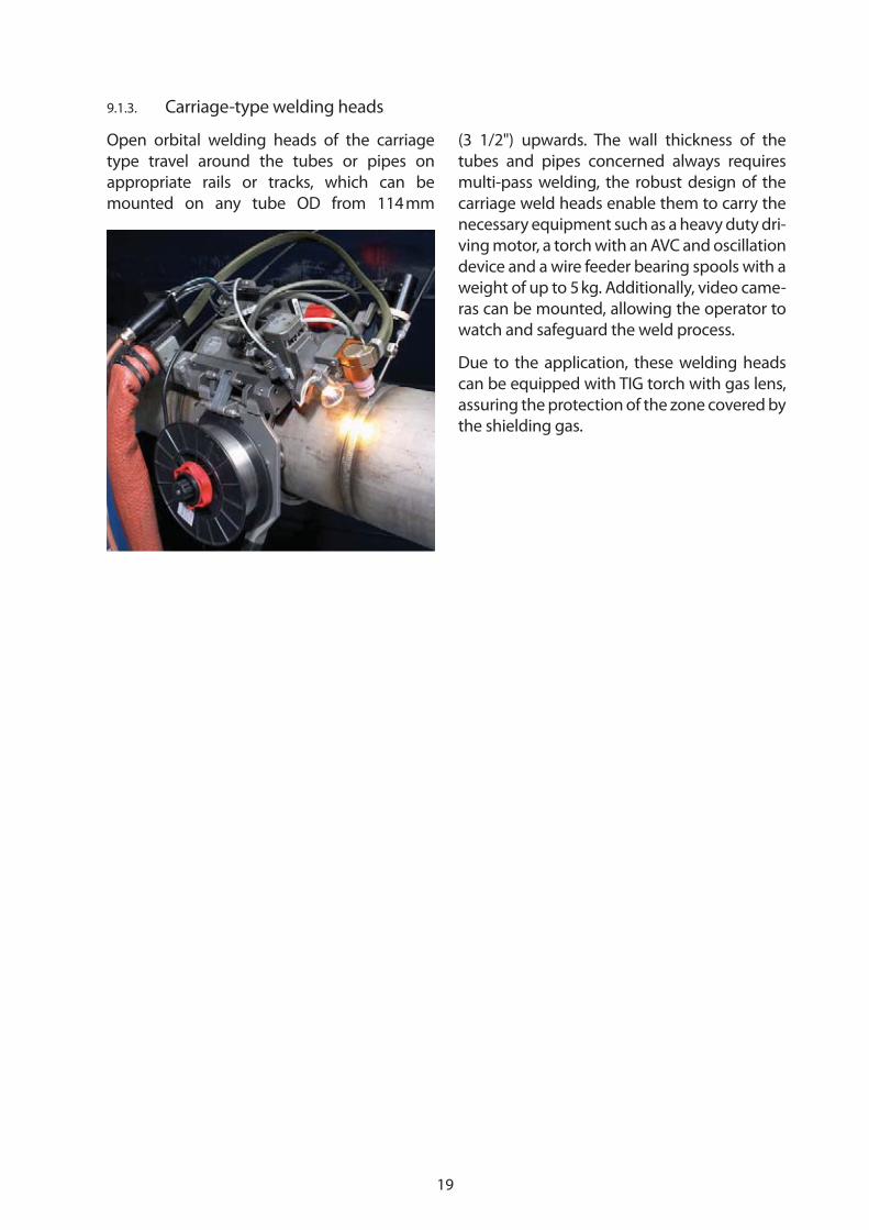
9.1.3. Carriage-type welding heads
Open orbital welding heads of the carriage
type travel around the tubes or pipes on
appropriate rails or tracks, which can be
mounted on any tube OD from 114 mm
(3 1/2") upwards. The wall thickness of the
tubes and pipes concerned always requires
multi-pass welding, the robust design of the
carriage weld heads enable them to carry the
necessary equipment such as a heavy duty dri-
ving motor, a torch with an AVC and oscillation
device and a wire feeder bearing spools with a
weight of up to 5 kg. Additionally, video came-
ras can be mounted, allowing the operator to
watch and safeguard the weld process.
Due to the application, these welding heads
can be equipped with TIG torch with gas lens,
assuring the protection of the zone covered by
the shielding gas.

20
9.2. Tube to tube sheet welding heads
9.2.1. Enclosed orbital tube to tube sheet welding heads without filler wire
Enclosed welding heads are designed for
TIG welding (GTAW) of tube to tube sheet
applications, if they can be accomplished
without filler wire. With these weld heads,
flush or slightly protruding tubes with a mini-
mum internal diameter of 9.5 mm (3/8") can
be welded, the maximum diameter being
33.7 mm (1 1/3").
The weld is carried out in an inert atmosphere
inside a welding gas chamber, providing very
good protection against oxidation.
For clamping, a mandrel is inserted into
the tube to be welded and expanded
mechanically.
By means of a weld lance which is mounted at
the front of the weld head, internal bore wel-
ding can be carried out at tube I.D. between
10 mm and 33.7 mm (13/32" and 1 1/3").
9.2.2. Open tube to tube sheet welding heads with or without filler wire
Open orbital tube to tube sheet weld heads
which can be used with filler wire cover the
whole range of applications from tubes with
an I.D. of 10 mm (13/32") up to tubes with a
maximum O.D. of 60 mm. The TIG torch tra-
vels around the tubes, which can be protru-
ding, flush or recessed.
The welding heads are equipped with a TIG-
torch with gas diffuser. A sufficient gas pro-
tection is achieved only at the zone around
the torch which is covered by the shielding
gas streaming out of the gas lens. If oxygen
sensitive materials need to be welded, the
gas protection can be improved by installing
a gas chamber.
The welding heads can be equipped with
an integrated wire feeder unit A pneuma-
tic clamping device can be used to hold the
weld head in working position on the tube
plate, enabling several welding heads to be
operated by just one person. Welding lances
allow the operator to carry out internal bore
welding with gapless joints behind a tube
sheet or a double tube sheet.
Tube to tube sheet welding head TS 34
Tube to tube sheet welding
head TS 2000
21
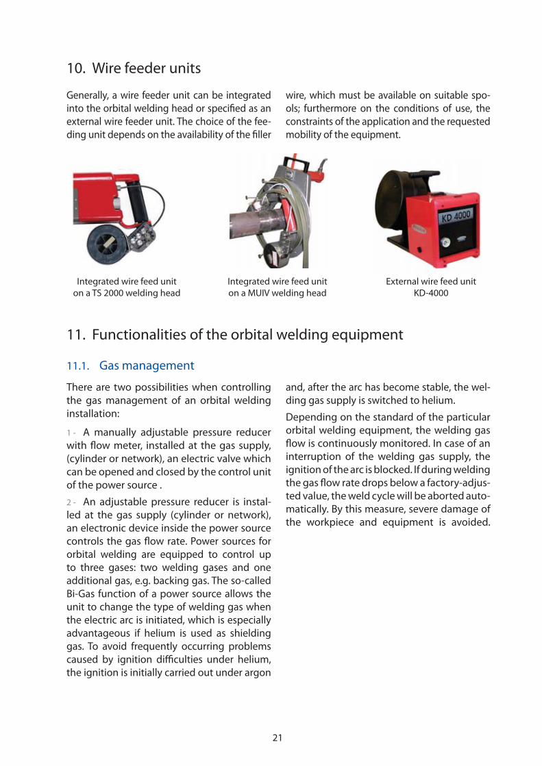
10. Wire feeder units
Generally, a wire feeder unit can be integrated
into the orbital welding head or specified as an
external wire feeder unit. The choice of the fee-
ding unit depends on the availability of the filler
wire, which must be available on suitable spo-
ols; furthermore on the conditions of use, the
constraints of the application and the requested
mobility of the equipment.
11. Functionalities of the orbital welding equipment
11.1. Gas management
There are two possibilities when controlling
the gas management of an orbital welding
installation:
1 - A manually adjustable pressure reducer
with flow meter, installed at the gas supply,
(cylinder or network), an electric valve which
can be opened and closed by the control unit
of the power source .
2 - An adjustable pressure reducer is instal-
led at the gas supply (cylinder or network),
an electronic device inside the power source
controls the gas flow rate. Power sources for
orbital welding are equipped to control up
to three gases: two welding gases and one
additional gas, e.g. backing gas. The so-called
Bi-Gas function of a power source allows the
unit to change the type of welding gas when
the electric arc is initiated, which is especially
advantageous if helium is used as shielding
gas. To avoid frequently occurring problems
caused by ignition difficulties under helium,
the ignition is initially carried out under argon
and, after the arc has become stable, the wel-
ding gas supply is switched to helium.
Depending on the standard of the particular
orbital welding equipment, the welding gas
flow is continuously monitored. In case of an
interruption of the welding gas supply, the
ignition of the arc is blocked. If during welding
the gas flow rate drops below a factory-adjus-
ted value, the weld cycle will be aborted auto-
matically. By this measure, severe damage of
the workpiece and equipment is avoided.
Integrated wire feed unit
on a TS 2000 welding head
Integrated wire feed unit
on a MUIV welding head
External wire feed unit
KD-4000
22
1
2
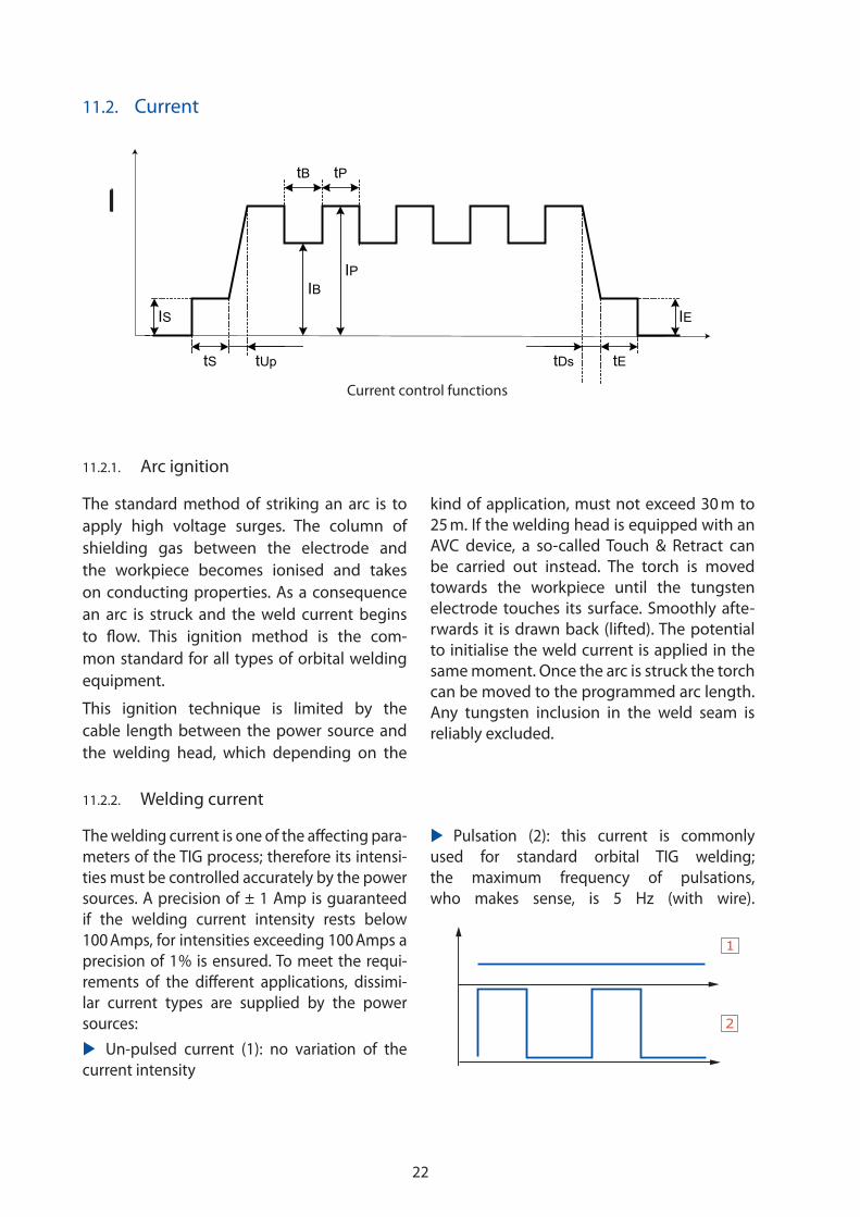
11.2. Current
11.2.2. Welding current
11.2.1. Arc ignition
Current control functions
The standard method of striking an arc is to
apply high voltage surges. The column of
shielding gas between the electrode and
the workpiece becomes ionised and takes
on conducting properties. As a consequence
an arc is struck and the weld current begins
to flow. This ignition method is the com-
mon standard for all types of orbital welding
equipment.
This ignition technique is limited by the
cable length between the power source and
the welding head, which depending on the
kind of application, must not exceed 30 m to
25 m. If the welding head is equipped with an
AVC device, a so-called Touch & Retract can
be carried out instead. The torch is moved
towards the workpiece until the tungsten
electrode touches its surface. Smoothly afte-
rwards it is drawn back (lifted). The potential
to initialise the weld current is applied in the
same moment. Once the arc is struck the torch
can be moved to the programmed arc length.
Any tungsten inclusion in the weld seam is
reliably excluded.
IB IP
tB tP
IS
tS tUp tDs tE
IE
The welding current is one of the affecting para-
meters of the TIG process; therefore its intensi-
ties must be controlled accurately by the power
sources. A precision of ± 1 Amp is guaranteed
if the welding current intensity rests below
100 Amps, for intensities exceeding 100 Amps a
precision of 1 % is ensured. To meet the requi-
rements of the different applications, dissimi-
lar current types are supplied by the power
sources:
�� Un-pulsed current (1): no variation of the
current intensity
�� Pulsation (2): this current is commonly
used for standard orbital TIG welding;
the maximum frequency of pulsations,
who makes sense, is 5 Hz (with wire).
23
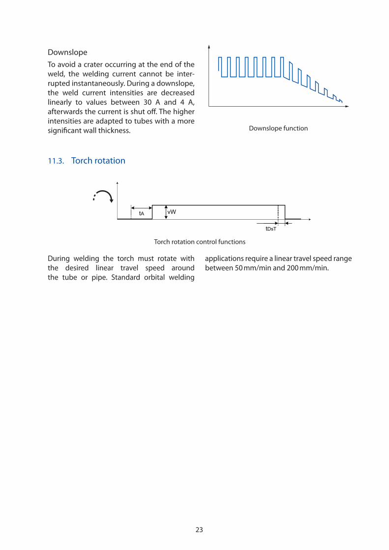
Downslope
To avoid a crater occurring at the end of the
weld, the welding current cannot be inter-
rupted instantaneously. During a downslope,
the weld current intensities are decreased
linearly to values between 30 A and 4 A,
afterwards the current is shut off. The higher
intensities are adapted to tubes with a more
significant wall thickness. Downslope function
11.3. Torch rotation
During welding the torch must rotate with
the desired linear travel speed around
the tube or pipe. Standard orbital welding
applications require a linear travel speed range
between 50 mm/min and 200 mm/min.
Torch rotation control functions
vWtA
tDsT

24
In most cases the travel speed remains un-
pulsed, but it can also become pulsed and
synchronized to the weld current pulsations.
It is possible to program different speeds
during base and pulse current. Usually, as in
the case of step pulsed welding, rotation stops
(V = 0 mm/min) during the high current level,
whereas during the base current period the
torch moves forward.
The achieved speed precision is 1 % of the pro-
grammed value. Welding equipment can be
operated using impulse emitters or tachome-
ter encoders on request.
These pulses are also processed by the
control system of the power source to iden-
tify the actual position of the torch relative
to the start point, which means that the pro-
gramming of a weld cycle can be carried out
using angular degrees instead of time spans.
Intuitive programming is possible because
one tour of the torch always covers 360° per
pass, independently of the linear welding
speed and the tube or pipe diameter.
11.4. Wire feeding
Power sources for orbital welding are equip-
ped to control different types of wire feeder
units; the attainable wire speeds range from
0 to 8,000 mm/min, a precision of about 1 %
is attained.
Standard functions of wire feeding which are
managed by all power sources are the control
of the wire start and stop as well as a pulsed
feeding rates. The wire feeding pulses can be
synchronised to the pulses of the weld cur-
rent; the wire speed is kept at a high level
when the weld current is at its high level, and
is decreased during low level current. The
independence between wire speed and weld
current offered by the TIG process allows the
reversal of synchronisation; the wire is fed at
a high speed when the current intensity is
low; the wire arrives at a small weld puddle
and melts with resistance. The mechanical
stability of the wire can be used to push the
bath of molten metal to get a convex root
pass surface at the inside of the workpiece.
At the end of welding, a wire retract function
allows the reversal of the feeding direction.
The wire end is drawn back a few millimetres,
avoiding the formation of a terminal wire ball
or, even worse, the wire resting stuck in the
weldment.
Expert information:
1 - Common diameters of wire for welding
purposes range between 0.6 mm and 1.2 m;
the best choice for standard orbital welding
is a proper wire with 0.8 mm diameter.
2 - The melting rate of the wire depends
not only on the precision of the wire feed
speed, but also on the precision of the
wire itself: a variation of 0.02 mm at a wire
with a diameter of 0.8 mm represents a
difference of already 5 % of added metal.
Wire feeding control functionstD
vDB
tDn
vDP
25
11.5.1. Theoretical approach
During welding, it is important to keep the arc length constant; but there are no simple
methods to measure it. In any case, if the welding conditions do not change, each particular
arc length corresponds to a related arc voltage. This phenomenon is used to control the dis-
tance between the electrode and the workpiece during welding.
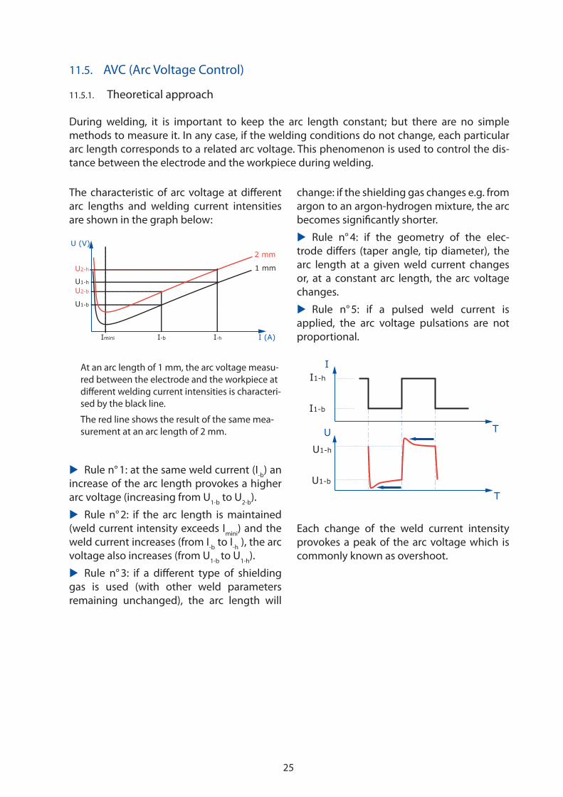
The characteristic of arc voltage at different
arc lengths and welding current intensities
are shown in the graph below:
U2-h
I-b I-h
U (V)
I (A)Imini
U1-h
U2-b
U1-b
2 mm
1 mm
At an arc length of 1 mm, the arc voltage measu-
red between the electrode and the workpiece at
different welding current intensities is characteri-
sed by the black line.
The red line shows the result of the same mea-
surement at an arc length of 2 mm.
�� Rule n° 1: at the same weld current (I-b
) an
increase of the arc length provokes a higher
arc voltage (increasing from U1-b
to U2-b
).
�� Rule n° 2: if the arc length is maintained
(weld current intensity exceeds Imini
) and the
weld current increases (from I-b
to I-h
), the arc
voltage also increases (from U1-b
to U1-h
).
�� Rule n° 3: if a different type of shielding
gas is used (with other weld parameters
remaining unchanged), the arc length will
change: if the shielding gas changes e.g. from
argon to an argon-hydrogen mixture, the arc
becomes significantly shorter.
�� Rule n° 4: if the geometry of the elec-
trode differs (taper angle, tip diameter), the
arc length at a given weld current changes
or, at a constant arc length, the arc voltage
changes.
�� Rule n° 5: if a pulsed weld current is
applied, the arc voltage pulsations are not
proportional.
I1-h
U1-b
U1-h
I
U
I1-b
T
T
Each change of the weld current intensity
provokes a peak of the arc voltage which is
commonly known as overshoot.
11.5. AVC (Arc Voltage Control)
26
11.5.3. Programmable distance between electrode and workpiece
Besides the AVC control, the torch position
can be determined by the programmed
distance between electrode and workpiece
function. Here, starting from a reference
value, the torch is moved by a motorized
slide over the selected distance in mm to the
desired height.
The mentioned function is often used to get
the electrode in position e.g. with tube to
tube sheet applications or, if special welding
tools are used, to follow the complex sur-
face geometry of a workpiece in piggyback
position.
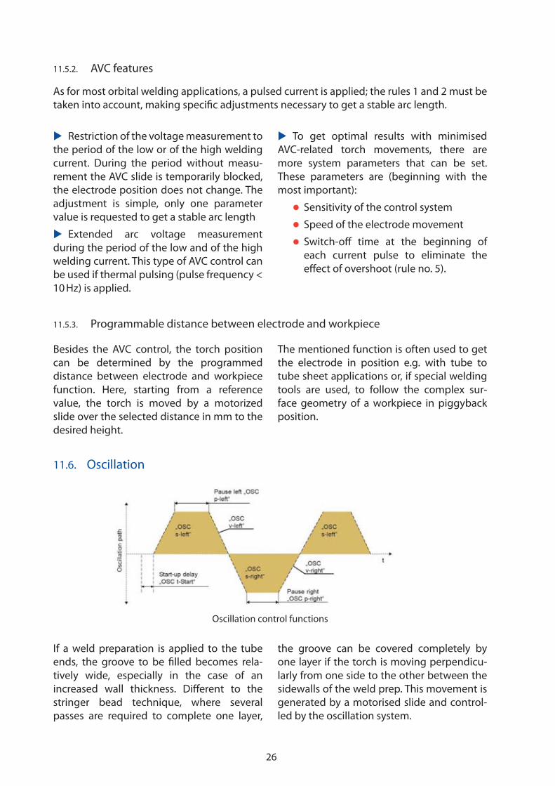
11.6. Oscillation
If a weld preparation is applied to the tube
ends, the groove to be filled becomes rela-
tively wide, especially in the case of an
increased wall thickness. Different to the
stringer bead technique, where several
passes are required to complete one layer,
the groove can be covered completely by
one layer if the torch is moving perpendicu-
larly from one side to the other between the
sidewalls of the weld prep. This movement is
generated by a motorised slide and control-
led by the oscillation system.
11.5.2. AVC features
As for most orbital welding applications, a pulsed current is applied; the rules 1 and 2 must be
taken into account, making specific adjustments necessary to get a stable arc length.
�� Restriction of the voltage measurement to
the period of the low or of the high welding
current. During the period without measu-
rement the AVC slide is temporarily blocked,
the electrode position does not change. The
adjustment is simple, only one parameter
value is requested to get a stable arc length
�� Extended arc voltage measurement
during the period of the low and of the high
welding current. This type of AVC control can
be used if thermal pulsing (pulse frequency <
10 Hz) is applied.
�� To get optimal results with minimised
AVC-related torch movements, there are
more system parameters that can be set.
These parameters are (beginning with the
most important):
�� Sensitivity of the control system
�� Speed of the electrode movement
�� Switch-off time at the beginning of
each current pulse to eliminate the
effect of overshoot (rule no. 5).
Oscillation control functions
27
Parameters needing to be set to get the
correct oscillation are width and speed of
the stroke, as well as the dwell time, during
which the torch remains at the end points
of its movement next to the sidewalls of the
groove.
It is possible to synchronise the torch oscilla-
tion with the pulsed current. For example, to
increase the penetration at the sidewall, the
high current intensity value is maintained
continuously during the dwell time.
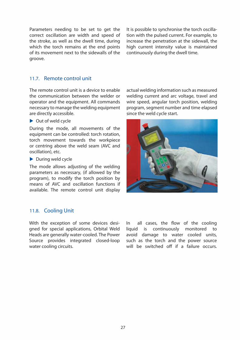
The remote control unit is a device to enable
the communication between the welder or
operator and the equipment. All commands
necessary to manage the welding equipment
are directly accessible.
�� Out of weld cycle
During the mode, all movements of the
equipment can be controlled: torch rotation,
torch movement towards the workpiece
or centring above the weld seam (AVC and
oscillation), etc.
�� During weld cycle
The mode allows adjusting of the welding
parameters as necessary, (if allowed by the
program), to modify the torch position by
means of AVC and oscillation functions if
available. The remote control unit display
actual welding information such as measured
welding current and arc voltage, travel and
wire speed, angular torch position, welding
program, segment number and time elapsed
since the weld cycle start.
11.8. Cooling Unit
11.7. Remote control unit
With the exception of some devices desi-
gned for special applications, Orbital Weld
Heads are generally water-cooled. The Power
Source provides integrated closed-loop
water cooling circuits.
In all cases, the flow of the cooling
liquid is continuously monitored to
avoid damage to water cooled units,
such as the torch and the power source
will be switched off if a failure occurs.
28
I
1 2 43 5 5b 7b6 6b 7 8 9 10
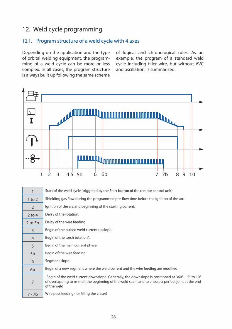
12. Weld cycle programming
1 Start of the weld cycle (triggered by the Start button of the remote control unit)
1 to 2 Shielding gas flow during the programmed pre-flow time before the ignition of the arc
2 Ignition of the arc and beginning of the starting current.
2 to 4 Delay of the rotation.
2 to 5b Delay of the wire feeding.
3 Begin of the pulsed weld current upslope.
4 Begin of the torch totation*.
5 Begin of the main current phase.
5b Begin of the wire feeding.
6 Segment slope.
6b Begin of a new segment where the weld current and the wire feeding are modified
7
-Begin of the weld current downslope. Generally, the downslope is positioned at 360° + 5° to 10°
of overlapping to re-melt the beginning of the weld seam and to ensure a perfect joint at the end
of the weld
7 - 7b Wire post feeding (for filling the crater)
12.1. Program structure of a weld cycle with 4 axes
Depending on the application and the type
of orbital welding equipment, the program-
ming of a weld cycle can be more or less
complex. In all cases, the program structure
is always built up following the same scheme
of logical and chronological rules. As an
example, the program of a standard weld
cycle including filler wire, but without AVC
and oscillation, is summarized.

29
7bEnd of wire feeding* (and wire retract if programmed). Generally, the end of wire feeding is posi-
tioned at approx. 360°
8 End of the torch rotation, begin of the end current.
9 Weld end.
9 to 10
Time period of post-gas flow to protect the weld zone of the workpiece until a sufficiently low
temperature has been reached and to protect the hot tungsten electrode against oxygen of the
atmosphere.
10 Shielding gas stop and end of the weld cycle.
* Depending on the expected result the functions may be programmed in a different chronological order.

30
12.3. Offline programming
The programming of weld cycles for very
complex applications and research tasks are
carried out offline by means of a personal
computer without connection to the system
controller.
The FPA-Xplorer software is designed for
the management of FPA 2020 and FPA 2030
Orbital programs and files. The intuitive
structure of the program enables the user
to access, edit and update data quickly and
easily from a central PC. This is carried out
via four tabs in which device properties, pro-
grams, actual values or alarm and event mes-
sages can be edited. With certain versions of
the FPA 2030 Orbital control, data can also be
accessed online.
The welding software is designed for a
Windows™ environment.
12.2. Interfaces for the programming of weld cycles
A recently introduced user-friendly Graphical
User Interface, (GUI), for orbital welding
equipment based on a PLC has been deve-
loped. The virtual synoptic is presented on
a 5,7" touchscreen; it allows not only the
complete weld data management but offers
all functions to assist the operator with the
development and finish of any orbital wel-
ding program. Some of the features are listed
below:
�� Complete documentation of the work-
piece data
�� Creation of chained weld cycles to carry
out a complete multi-pass weld sequence
�� Detailed description of boundary parame-
ters, i.e. mechanical adjustments of devices,
type and characteristics of gases used, elec-
trodes, filler wire etc.
�� Computer-aided optimisation of welding
parameters for tube to tube and tube to tube
sheet applications
�� Automatic generation of programs for
orbital fusion welding.
FPA 2020 / FPA 2030 touchscreen

31
During a weld cycle, the essential parameters
values of weld current intensity, arc voltage,
travel speed and wire feed speed are mea-
sured and memorised cyclically. To allow a
complete documentation of the weld, a weld
cycle report including these measurements
and the actual date and time can be printed
whenever a weld cycle has been completed.
The weld cycle programs can be documen-
ted. The printouts may be used to verify that
all parameters are set correctly and provided
as proof for quality assurance purposes. The
printout contains the program name, the
parameter values and the range of modifica-
tion allowed to the operator during the weld
process by means of the remote control unit.
13. Real time data recording
13.1. In summary
If a quality assurance system such as ISO 9000
has to be respected; only calibrated equip-
ment can be used for the manufacturing of cer-
tain components.
The expression calibration is specified by
regulating standards. It means that measu-
ring instruments installed in the power
source or within the connected devices
of the welding equipment have to meet
special requirements, they must be related
to national or international standards or
certified reference materials.
Calibration needs specific testing equipment
and procedures and can only be carried out
by an approved organisation, for example
the manufacturer of the welding equip-
ment, the quality assurance division of the
user, or an independent external company.
13.2. Integrated real-time
data recording

32
14. Tube to Tube welding
Parameters such as values for pulsing cur-
rent, background current, arc voltage, tra-
vel speed, wire feed speed, actual segment,
torch-position are recorded. The progress of
the weld cycle can be monitored and occurs
as a graph on the display.
The data acquisition system allows the ope-
rator to set limits for the different weld para-
meters. In this case, the concerned parameter
values are continually compared to a pre-
viously recorded defect-free sample weld.
13.3. Actual value recording (AVR)
14.1. Applications
Fusion welds of thin-walled tubes cover a
wide range of applications. Clients include
for example: semiconductor industry, bio-
chemistry, instrumentation, food and beve-
rage, pharmaceutical industry, chemical/
sanitary industry, and aeronautics/aerospace.
In most cases, the tubes are made of austeni
tic stainless steel, but nickel alloys as well as
titanium and its alloys can also be found. The
range covers diameters from 1.6 to 170 mm;
with wall thicknesses of varying between
0.2 and 3.2 mm.
14.2. Equipment
Preferentially, fusion welds are carried out using machines such as the FPA 2020 or FPA 2030
system controllers, combined with enclosed orbital welding heads. Depending on the appli-
cation, the enclosed welding heads can be divided in 2 groups.

33
Enclosed chamber welding
head UHP 500-2
14.2.1. UHP enclosed chamber welding heads
The UHP weld heads are specially designed
to meet the requirements of high purity
applications. Inside the weld head, the shiel-
ding gas is flowing separately through a high
purity gas circuit and arrives directly at the
weld zone without any contact to gears or
rotating parts. Thus, the danger of particle
contamination is significantly reduced.
Welding heads of the UHP type provide dis-
tinct reduced radial and axial dimensions;
they are especially adapted to the welding
of small diameter tubes. These welding
heads are designed in a modular structure.
The drive motor is integrated into a unique
handle and can be combined with 3 gear
modules UHP 250-2 for tube sizes up to
6.35 mm (1/4"), UHP 500-2 for up to 12.7 mm
(1/2"), and UHP 1500 for diameters up to
33.7 mm (1 1/3"). Interchangeable clamping
cassettes for example allow preparation of
the work pieces independently in advance.
The handle with the motor is only attached
during the time which is necessary to accom-
plish a weld.
Clamping cassettes and flexible Tube Clamp
Inserts (TCI) made from titanium are perfectly
adapted to fit the typical standard outside
diameters of tubing used in semi-conductor
applications or pure gas supplies. The asym-
metric shape of the weld head allows the
joining of fittings with a short stick-out, and
fixture blocks ensure reliable centring, align-
ment and clamping of all kinds of common
micro-fittings.

34
Open welding heads can be used to weld
with or without filler metal. Two important
differences compared to enclosed welding
heads should be pointed out:
The gas protection does not cover the whole
welding zone, but only a limited zone around
the torch. This can cause problems in case of
applications where oxygen-sensitive metals
or alloys have to be welded
The straight length of the workpiece at the
clamping side of an open welding head is
much more important than the length nee-
ded by enclosed welding heads.
14.2.3. Open welding heads
14.2.2. MW enclosed chamber welding heads
The MW range of enclosed welding heads
has been exclusively designed for auto-
genous welding without wire. They fit
tube O.D. between 6 mm and 170 mm. In
addition to the perfect weld quality which
can be obtained with these kinds of welding
head, the inbuilt cooling circuit, together
with the high temperature-resistant mate-
rials used in their construction, provide a
considerable increase in productivity. Fast
operation is ensured by the remote control
unit buttons which are integrated comfor-
tably into the handle.
Fittings and accessories with a short stick-out
can be welded by means of an elbow-kit with
off-set electrode holder.
MW series Enclosed
chamber welding head
MU series Open welding head

35
14.3. Calculation of weld parameters values
Depending on the diameter and wall thic-
kness of the tubes to be joined the parameter
values for fusion welding without wire can
be calculated. The calculations are based on
formulas developed for stainless steel of the
300 series (e.g. 316 L), but the results can be
transposed for other materials.
In any case, the validity of the calculated
results must be confirmed by test welds.
Materials with the same designation, and of
an equal nominal composition, may still have
very different welding properties (see also
chapter 14.7 - Chemical composition and
repeatability of welds).
Menu to access existing weld procedures
or calculated parameters
Autogenous orbital welding requires a pre-
cise butt end preparation of the tubes. To
obtain such precise square edges, the pre-
paration should be carried out with a special
bevelling machine. Burrs must be removed
completely and the tube ends must fit
exactly without any gap. No grease, moisture
or other types of contaminations are allowed
around the welding zone.
Before the welding process can be started,
the tubes must be positioned without misa-
lignment and fixed by tack welding. During
the tack welding, to avoid any discoloration
or oxidation inside the tubes, they must be
purged with backing gas. Due to the high
melting temperature of chromium oxides
blue or dark spots originated by tack welds
can provoke a lack of fusion during the final
weld operation.
The diameter of the tack welds must remain
smaller that the width of the final weld
seam. To ensure the complete re-melting
of the tacking points during the welding
process, the tack welding operations have to
be carried out without filler wire.
Internal mechanical fixing devices can be
helpful for positioning and welding, these
devices are often connected to systems to
control the backing gas flow rate; they are
advantageous when used if SMS-fittings
have to be joined for applications of the food
and beverage industry.
Expert information: To reinforce the mecha-
nical strength of an autogenously welded
seam, additional material can be obtained by
a preparation of one tube end with an over-
lapping collar . Another possibility is to
place a welding insert into the gap between
the tubes . A thoroughly selected choice
of the insert alloy allows welding dissimilar
materials which otherwise cannot be joined
by autogenous welding.
1
2
14.4. Joint preparation

36
Direct current [A] Alternating current [A]
Electrode
diameter
Straight
polarity DCEN
Reverse
polarity DCEP
Balanced
wave
0.020’’ 0.05 mm 5-20 10-20
0.04’’ 1.0 mm 15-80 20-30
1/16’’ 1.6 mm 70-150 10-20 30-80
3/32’’ 2.4 mm 150-250 15-30 60-130
1/8’’ 3.2 mm 250-400 25-40 100-180
5/32’’ 4.0 mm 400-500 40-55 160-240
3/16’’ 4.8 mm 500-750 55-80 190-300
1/4’’ 6.4 mm 750-1100 80-125 325-450
14.5. Electrode preparation
To maintain a constant and compact form of
welding arc, tungsten electrodes which will
be used for mechanised or automatic wel-
ding should be prepared with a tapered end.
The diameter of the electrode, the grinding
angle "A" and the diameter "M" of the flatte-
ned tip depend on the weld current intensity.
The grinding angle "A" should have a value
between 18° and 30°, the flattened tip dia-
meter should be prepared between 0.1 mm
and 0.5 mm. Higher weld current intensities
request a larger grinding angle and greater
flattened tip diameter.
The length of the electrode must be calcula-
ted and cut dependant on the type of weld
head, the OD of the tubes to be welded and
the specified arc length. In many cases it is
difficult to prepare the electrodes with the
necessary precision on site even by using
an electrode grinder. The purchase of ready-
to-use electrodes on the market is often
considered to be an efficient and economic
solution.
Expert information: The tungsten electrodes
should always be changed preventively, so
a considerable amount of welding problems
and defects (arc instabilities, ignition difficul-
ties) can be avoided. Delicate applications
sometimes require the electrode to be chan-
ged after each weld.
M
A
Electrode preparation
Electrode diameters to be selected for different welding current intensities

37
14.6. Backing gas
During orbital welding, the inner surface of
the tubes must be protected against oxida-
tion. Therefore, the interior of the tube sys-
tem is purged by backing gas. The purity of
the backing gas depends on the required
weld quality. Before the weld can be started,
a sufficient purge time must elapse, allowing
the backing gas to remove the oxygen out of
the system. The remaining oxygen content of
the backing gas can be analysed at the outlet;
if it has decreased to an acceptable value, the
welding operation can begin. Usually in the
case of UHP applications (Ultra High Purity)
the oxygen level must fall below 10 PPM
(Parts per Million), i.e. less than 0.001 %.
Expert information: The supply of ultra-
pure process gas requires that it passes
through the tubes without being contami-
nated by moisture, oxygen, particles or other
contaminants.
During welding, the specified values of flow
rate and internal pressure of the backing gas
must be respected and kept constant. The
internal pressure must be controlled because
excessive pressure will produce a root weld
with a concave surface at the outside or, even
worse, cause a weld bead short circuit.
If tubes with small diameters below
9.52mm (3/8") are welded, the internal pres-
sure can be used to prevent any excess of
convexity or inside diameter reduction.
Expert information: A light heat tint, due to
remaining oxygen in the backing gas, can be
removed by passivation.
0.001 % 0.008 % 0.03 %
Influence of oxygen content in the backing gas
14.7. Chemical composition and repeatability of the welds
Several problems occurring during the wel-
ding of stainless steel can be caused by low
sulphur content of the base metal. The sul-
phur content influences the surface tension
of the molten metal, high sulphur grades are
characterized by a narrow deep weld profile.
Low sulphur contents cause a very wide but
shallow weld bead with drastically reduced
penetration, which can be explained by a
phenomena named the Marangoni effect.
If a workpiece with very low sulphur content
should be joined to a second one with high
sulphur content, the arc can be deflected
completely to the part with the lower sulphur
content, thus excluding any acceptable stan-
dard weld operation. In some cases, a double
non-stop run of the welding procedure may
solve the problem.

38
15. Tube to Tube or Pipe to Pipe orbital welding with filler wire
15.2. Choice of the equipments
For orbital welding with additional filler wire,
standard equipment with 4 controlled axes
(shielding gas flow, weld current intensity,
torch rotation speed and wire feeding speed)
or with 6 axes (4 axes + AVC and oscillation)
can be used.
Independently from economic or other pro-
ject-related considerations, the table below
shows the technical requirements for 4 or 6
axes equipment to be used:
Type of equipment
Criteria 4 axes 6 axes
Wall thickness
to be welded
small (< 4 mm) + +
medium and thick (> 4 mm) - +
Accessibilityreduced + -
free + +
Weld sequencesimple + +
difficult - +
Level of automationlow + +
high - +
15.1. Applications
For several reasons, it can become neces-
sary to apply filler metal in orbital welding
procedures:
�� Wall thickness of the tubes requires a
preparation of their ends
�� Tubes or pipes to be welded are made
of different base metals
�� The weld must be reinforced
�� Strength and/or corrosion resistance
are compromised by fusion welding.
Tube-to-tube welding applications with the
addition of filler wire are often demanded in
the field of energy production (power plants)
and chemical or petrochemical industries.
A wide range of base materials are used:
�� Plain carbon steel
�� Low-alloyed chromium or chromium
manganese containing carbon steel
�� High-alloyed chromium nickel steel
(austenitic or with an austenite-ferrite
crystal structure)
�� Nickel base alloys (like e.g. Inconel®-
alloys or Hastelloy®-alloys)
�� Titanium and its alloys.
Although the tube dimensions differ very
much, the great majority is to be found in the
range of:
�� 26.9 mm and 219 mm (¾" and 8")
diameter
�� 2.77 mm to 12.7 mm wall thickness

39
15.3. Weld preparation
The standard preparation for the manual wel-
ding of tubes, bends, T-pieces and flanges is a
V-joint with a gap. For different reasons, this
type of preparation cannot be used for orbi-
tal welding (a gap is inapplicable in orbital
TIG welding, tack welding points are impos-
sible to remove, backing gas protection can-
not be obtained, etc.).
Preparations for orbital welding are always
designed as a joint without any gap at
the root face. For accessibility reasons, the
angles of standard V preparations have to be
increased to 30° or even 37°. With this type of
joint a regular penetration cannot be obtai-
ned; on the contrary, depending on the weld
position significant concavities occur.
To avoid these problems, and to get the desi-
red uniform penetration, a J preparation with
a collar of the width L and the thickness T has
to be selected. Indications about the recom-
mended geometry of the preparation with
respect to the tube diameter and thickness
are given in the table below:
Tube range(mm)
Angle(°)
Collar(mm)
Wall thickness (mm)
A T L
3<E 630°
1 2
E 61,5 2
10 E 15 20°
Expert information:
For automatic welding, the I.D. is often machi-
ned to get a thickness T with an acceptable
tolerance (± 0.2 to 0.3 mm).
To ensure the necessary precision and repea-
tability of the weld preparation, machines for
mechanical tube end preparation must be
used. Two types of machines are available on
the market:
�� Stationary installed equipment desig-
ned to be used in the workshop
�� Electric or pneumatic mobile machines
which can be hand-carried to machine
small batches or to be used on site.
In the case of reduced accessibility of the
work area, equipment with 4 controlled axes
should be preferred. If easy implementation
of the welding tool is required, the equip-
ment with 6 controlled axes should be the
choice that is always recommended.
30 ° 30 °
G
Tube end preparation commonly
used for manual tube welding
Recommended tube end preparation
for orbital TIG welding
A L
T
E
40
To remove all traces of Rust as well as Oil,
Carbon or Calamine Oxide Scale, the inside
and the outside of tubes made from carbon
steel must be machined.
Expert information: Metals which can be
magnetised must be inspected: no rem-
nant of magnetism or at least a very low
flux density (less than 3 gauss) is acceptable.
Otherwise, welding problems or defects (lack
of penetration, lateral sticking or porosity)
can occur.
15.4. Positioning of the tubes
Before orbital welding can be started, the
tubes must be positioned and tack welded;
generally a maximum misalignment (high/
low) of half of the land thickness T is tole-
rated. In order to avoid penetration faults
during the laying of the root pass, tack wel-
ding must be carried out without, or at least
with very low wire input. The prepared tube
ends must perfectly fit together: no gap is
permitted.
If stainless steel, nickel base alloys or titanium
and its alloys have to be welded, a protection
by backing gas is obligatory. In fact, carbon
steel can be welded without backing gas, but
a lower repeatability and an increasing repair
rate of the welds must be accepted.
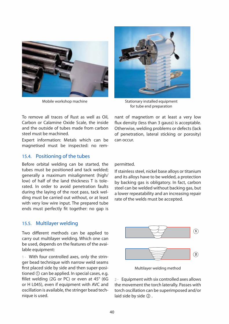
15.5. Multilayer welding
Two different methods can be applied to
carry out multilayer welding. Which one can
be used, depends on the features of the avai-
lable equipment:
1 - With four controlled axes, only the strin-
ger bead technique with narrow weld seams
first placed side by side and then super-posi-
tioned can be applied. In special cases, e.g.
fillet welding (2G or PC) or even at 45° (6G
or H L045), even if equipment with AVC and
oscillation is available, the stringer bead tech-
nique is used.
2 - Equipment with six controlled axes allows
the movement the torch laterally. Passes with
torch oscillation can be superimposed and/or
laid side by side .
1
2
Mobile workshop machine Stationary installed equipment
for tube end preparation
Multilayer welding method
41
Multilayer welding with the stringer bead
technique is quite complicated and time-
consuming, as the process has to be inter-
rupted after each pass and mechanical
adjustments need to be made: the late-
ral position of the torch and the distance
between the previous pass and the electrode
must be corrected. These adjustments can
only be executed if the particular parts of the
welding head are accessible in its working
position.
Welding equipment with six controlled
axes significantly reduces the time requi-
red for manual interventions. With the AVC
function the distance between electrode
and workpiece is controlled, the oscillation
allows coverage of the entire joint width or
to position the torch laterally. Once the torch
is positioned above the joint, the electrode
will be centred in the gap automatically. The
different passes of a weld can be chained, the
winding up of the hose and supply cables
can also be executed automatically, and so
the operator is not distracted by repetitive
actions and can fully concentrate on supervi-
sing the welding process
15.6. AVC requires precise electrode geometry
If tungsten electrodes are used for automatic
orbital welding, it must be ensured that their
geometry remains absolutely the same. Even
small variations of the shape or dimension
cause significant changes of the arc voltage,
which is used as a base value by the AVC
control (see chapter 11.5.1). The difference
of the arc voltage will be transformed by the
AVC control to a different arc length which
provokes differences of the melting bath size.
Expert information: An increased arc length
provokes the loss of the arc pressure and can
cause poor penetration and a concave sur-
face geometry. If the arc length is too short,
the electrode will be rapidly deteriorated.
15.7. Backing gas
For the manual welding of carbon steel a
backing gas protection is not mandatory, the
inside of the tubes is protected by the shiel-
ding gas passing through the gap at the bot-
tom of the V joint.
In the case of orbital welding with a
J-preparation without any gap at the root
face, backing gas protection is strongly
recommended. The formation of refractory
calamine, which occurs distinctly if steel with
higher manganese silicon content is welded,
can be suppressed. Thus a better repeatabi-
lity of the weld will be achieved. The backing
gas types to be used for different base metals
are listed at chapter 3.5.2.
15.8. Boundary parameters
The importance of boundary parameters, i.e.
parameters which are not directly program-
med at the machine, is often underestimated
in orbital welding. The consequences are low
repeatability of the welds and a decreased
productivity. Some of the boundary parame-
ters are listed below:
�� Shielding gas: type, purity, flow rate
�� Backing gas: type, purity, flow rate
�� Gas lens: type and size
�� Ceramic nozzle: size, diameter and length
�� Electrode: type, diameter, end prepara-tion and stick out
�� Wire: grade and diameter; cast n°, entry angle, impact point
�� Inter-pass temperature
�� Ground cable position and connection.

42
-
++
-
15.9. Geometrical adjustments
For all applications the geometrical adjust-
ments concerning the torch and the wire
guide must be carried out thoroughly and
documented clearly.
Se
H De-f Sf
�
1 - The angle � between the tungsten and
the arriving wire should be adjusted to a
value between 50° to 80°.
2 - The wire distance De-f to the electrode
should be adjusted between 1.5 mm and
3 mm. For the root pass the larger value is
recommended to use the kinetic energy of
the wire to push the weld bead through and
obtain some root convexity. For the filler and
cap passes it is recommended to reduce the
distance to 2 mm. By this, the wire is closer to
the arc and melts easily. More wire can be fed
and cold wire defects are avoided.
3 - The wire stick-out Sf should be adjusted
between 8 and 12 mm. If this distance is too
short the wire nozzle will burn or stick. If the
distance is too great the wire can twist in any
direction and, for example, contaminate the
tungsten electrode.
4 - The arc gap H should be adjusted
between 2 and 3 mm. In the case of 6 axes
equipment the distance will be controlled by
the AVC device. For a root pass weld the arc
gap can be reduced to 1 mm.
15.10. Possibilities to increase the performance of orbital TIG welding
Orbital GTAW welding with cold wire is an
adequate choice for standard applications
which require high quality levels but com-
pared to other arc welding processes, the
deposition rate of the TIG process is relatively
low (0.15 to 0.5 kg/h). In order to boost the
efficiency of the process it is possible to use
the hot wire technique.
15.10.1. Hot wire TIG welding
Increasing productivity without quality losses
can be achieved using the hot wire TIG pro-
cess. In this case, the filler wire is heated up by
an additional current. This hot wire current is
supplied by a second power source. The hot
wire technique leads to appreciable higher
deposition rates, i.e. 1 kg /h for orbital welding
and much more for cladding applications.
Principle of hot wire TIG welding
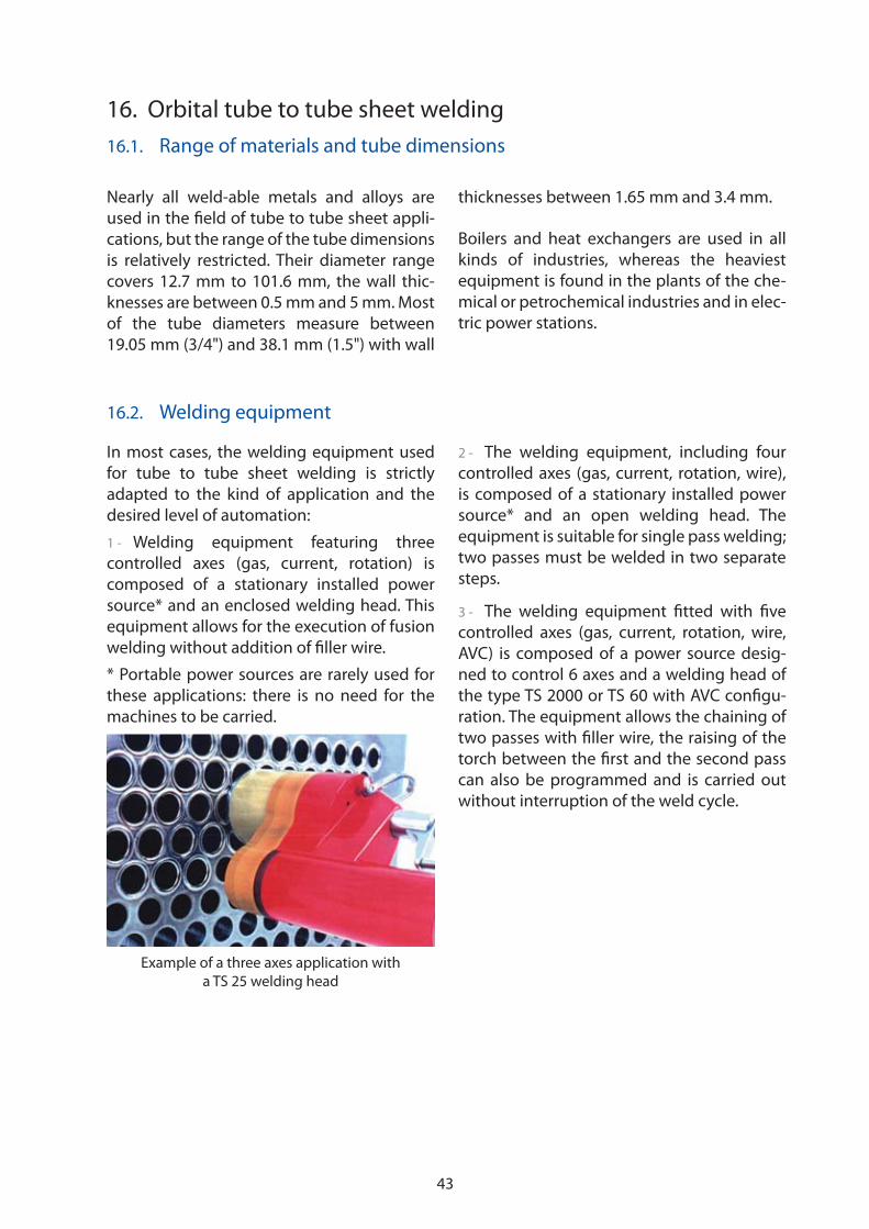
43
16. Orbital tube to tube sheet welding
16.1. Range of materials and tube dimensions
Nearly all weld-able metals and alloys are
used in the field of tube to tube sheet appli-
cations, but the range of the tube dimensions
is relatively restricted. Their diameter range
covers 12.7 mm to 101.6 mm, the wall thic-
knesses are between 0.5 mm and 5 mm. Most
of the tube diameters measure between
19.05 mm (3/4") and 38.1 mm (1.5") with wall
thicknesses between 1.65 mm and 3.4 mm.
Boilers and heat exchangers are used in all
kinds of industries, whereas the heaviest
equipment is found in the plants of the che-
mical or petrochemical industries and in elec-
tric power stations.
16.2. Welding equipment
Example of a three axes application with
a TS 25 welding head
In most cases, the welding equipment used
for tube to tube sheet welding is strictly
adapted to the kind of application and the
desired level of automation:
1 - Welding equipment featuring three
controlled axes (gas, current, rotation) is
composed of a stationary installed power
source* and an enclosed welding head. This
equipment allows for the execution of fusion
welding without addition of filler wire.
* Portable power sources are rarely used for
these applications: there is no need for the
machines to be carried.
2 - The welding equipment, including four
controlled axes (gas, current, rotation, wire),
is composed of a stationary installed power
source* and an open welding head. The
equipment is suitable for single pass welding;
two passes must be welded in two separate
steps.
3 - The welding equipment fitted with five
controlled axes (gas, current, rotation, wire,
AVC) is composed of a power source desig-
ned to control 6 axes and a welding head of
the type TS 2000 or TS 60 with AVC configu-
ration. The equipment allows the chaining of
two passes with filler wire, the raising of the
torch between the first and the second pass
can also be programmed and is carried out
without interruption of the weld cycle.

44
Fusion defects occurring on the ground
of a V-preparation
3 - In some cases, if a good thermal conduc-
tion is requested, the play between the tube
and the bore must be eliminated by a slight
expansion of the tube. Play is necessary
for the assembly of the apparatus before
the welds are carried out, but if clearances
become too great, problems of repeatability
may occur. However, it is difficult to specify a
maximum amount of play; it depends on the
demanded weld quality and the thickness of
the tube.
Expert information: To get optimised cen-
tring tools for the tube to tube sheet welding
heads, each order must be accompanied by
information about the depth of the expan-
sion and the tube diameter at the expanded
zone as well as the original diameter.
4 - The contact zone between the tube and
the tube sheet must be clean. Grease, oil or
other residues from the tube manufacturing
or machining can cause the formation of
unacceptable blowholes, with outlets on the
surface or enclosed in the welds.
5 - A strong expansion of the tubes inside
the tube sheet must never be carried out
before automatic welding. A strong expan-
sion (with or without longitudinal grooves
in the bore) causes almost always explosive
degassing effects which make automatic wel-
ding impossible.
16.3. Specific requirements of tubes and weld preparations
Compared to manual welding, the planning
of the orbital tube to tube sheet welding
requires some more specific attention:
1 - The tubes have to be seamless (or with
flattened weld); concentricity faults between
the inner and the outer diameter must be limi-
ted to a minimum to allow the repeatability
of the electrode positioning. With standard
applications, (flush, protruding or recessed
tubes) the torch is aligned at the inside of
the tube whereas the welding is carried out
at the external diameter. Concentricity faults
would cause unacceptable variations of the
distance between workpiece and electrode
and thus directly alter the arc length.
2 - As with V-joints it is virtually impossible
to ensure reliable melting of the base of the
tube edge, especially in the vertically down
position, (fusion defects are to be seen on
macrographic sections), these joints have to
be replaced by J-preparations.
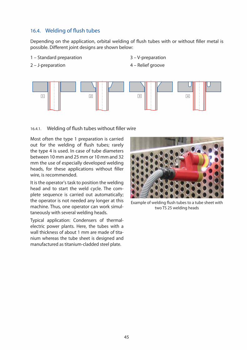
45
16.4. Welding of flush tubes
16.4.1. Welding of flush tubes without filler wire
1 32 4
Depending on the application, orbital welding of flush tubes with or without filler metal is
possible. Different joint designs are shown below:
1 – Standard preparation
2 – J-preparation
3 – V-preparation
4 – Relief groove
Example of welding flush tubes to a tube sheet with
two TS 25 welding heads
Most often the type 1 preparation is carried
out for the welding of flush tubes; rarely
the type 4 is used. In case of tube diameters
between 10 mm and 25 mm or 10 mm and 32
mm the use of especially developed welding
heads, for these applications without filler
wire, is recommended.
It is the operator's task to position the welding
head and to start the weld cycle. The com-
plete sequence is carried out automatically;
the operator is not needed any longer at this
machine. Thus, one operator can work simul-
taneously with several welding heads.
Typical application: Condensers of thermal-
electric power plants. Here, the tubes with a
wall thickness of about 1 mm are made of tita-
nium whereas the tube sheet is designed and
manufactured as titanium-cladded steel plate.

46
Example of welding flush tubes to a tube sheet with a
TS 2000 welding head
A B C
16.4.2. Welding of flush tubes with addition of filler wire
Welding equipment fitted with four or five
controlled axes can be used for this applica-
tion; the open tube to tube sheet welding
head should be configured with devices
adapted to the requirements:
�� Integrated or external wire feeder unit
�� With or without AVC
�� With or without shielding gas cham-
ber (for the welding of titanium or
zirconium)
�� Torch angle of 0° or 15°.
Expert information: The AVC function is
recommended especially for the welding of
flush tubes.
Generally, the tube end preparations are
of the type 1, 2 or 3. If a preparation of the
tube sheet is carried out, the V-joint can be
avoided. With this type of preparation, there
is always the risk of incomplete penetration
of the root. A J-preparation (with or without
radius) should be preferred, if the depth of
the bevelled edge exceeds 1.5 mm, the tube
end should be positioned at the half of it.
The maximum value of the tube end to be
recessed is 50 % of the tube thickness, the
tube becomes flush by the weld.
Depending on the dimensions and the requi-
red weld thickness one or two passes are
necessary. One tour of the torch is always
applied in case of a pass for tightness; the
layers for mechanical resistance often require
a second tour.
16.5. Welding of protruding tubes
Protruding tubes are always welded with addition of filler wire, but in some cases the weld is
beginning with a fusion pass. As shown below, different joint designs are possible.
A - Standard preparation without groove
B – J-preparation
C – V-preparation
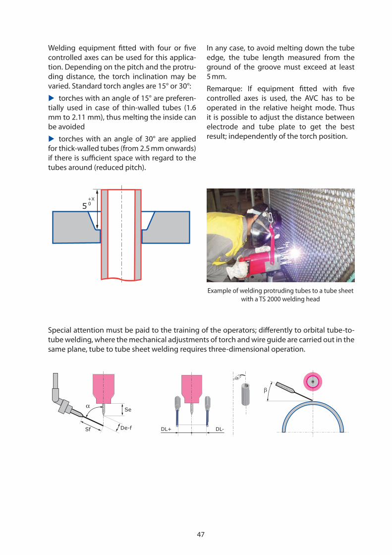
47
Welding equipment fitted with four or five
controlled axes can be used for this applica-
tion. Depending on the pitch and the protru-
ding distance, the torch inclination may be
varied. Standard torch angles are 15° or 30°:
�� torches with an angle of 15° are preferen-
tially used in case of thin-walled tubes (1.6
mm to 2.11 mm), thus melting the inside can
be avoided
�� torches with an angle of 30° are applied
for thick-walled tubes (from 2.5 mm onwards)
if there is sufficient space with regard to the
tubes around (reduced pitch).
In any case, to avoid melting down the tube
edge, the tube length measured from the
ground of the groove must exceed at least
5 mm.
Remarque: If equipment fitted with five
controlled axes is used, the AVC has to be
operated in the relative height mode. Thus
it is possible to adjust the distance between
electrode and tube plate to get the best
result; independently of the torch position.
Special attention must be paid to the training of the operators; differently to orbital tube-to-
tube welding, where the mechanical adjustments of torch and wire guide are carried out in the
same plane, tube to tube sheet welding requires three-dimensional operation.
5+X0
Example of welding protruding tubes to a tube sheet
with a TS 2000 welding head
Se
De-fSf
�
DL+ DL-
�

48
D E F G
Welding behind the tube plate
of a double-walled collector
D: Standard preparation without groove
E: J-preparation
F: V-preparation
G: Welding behind the tube plate
Welding equipment fitted with four or five
controlled axes and an open tube to tube
sheet welding head can be used for the appli-
cation D, E and F.
The preparation of the type G is frequently
used in the petrochemical industry; welding
equipment with six controlled axes and a
welding head with separate clamping device
have to be used. This type of application
generally requires a specific project to study
the best adaptation of clamping tools and
welding procedures.
Expert information: Different to those appli-
cations with protruding tubes, in the case of
recessed tubes a V preparation of the tube
plate is possible. If joint preparations of the
type E or F are applied, the tubes may pro-
trude slightly from the base of the groove.
Depending on the dimensions, and the
required weld thickness, one or two passes
are necessary. One tour of the torch is always
applied on the first pass for tightness; layers
needed for mechanical strength and wear
resistance will often require a second tour.
Particular application: Welding behind the
tube plate of a double-walled collector for
air-cooling or fluid condensation. The AVC
operation is indispensable to make the weld
in this application.
16.6. Welding of recessed tubes
Different joint designs are shown below:
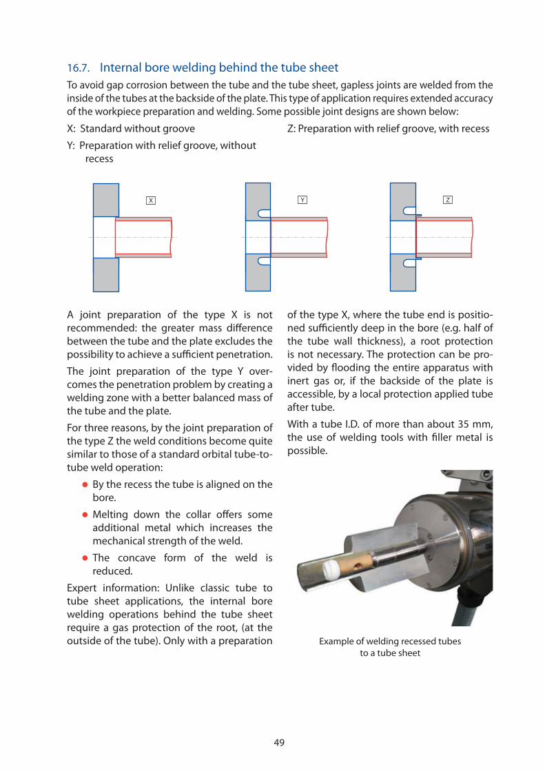
49
A joint preparation of the type X is not
recommended: the greater mass difference
between the tube and the plate excludes the
possibility to achieve a sufficient penetration.
The joint preparation of the type Y over-
comes the penetration problem by creating a
welding zone with a better balanced mass of
the tube and the plate.
For three reasons, by the joint preparation of
the type Z the weld conditions become quite
similar to those of a standard orbital tube-to-
tube weld operation:
�� By the recess the tube is aligned on the
bore.
�� Melting down the collar offers some
additional metal which increases the
mechanical strength of the weld.
�� The concave form of the weld is
reduced.
Expert information: Unlike classic tube to
tube sheet applications, the internal bore
welding operations behind the tube sheet
require a gas protection of the root, (at the
outside of the tube). Only with a preparation
of the type X, where the tube end is positio-
ned sufficiently deep in the bore (e.g. half of
the tube wall thickness), a root protection
is not necessary. The protection can be pro-
vided by flooding the entire apparatus with
inert gas or, if the backside of the plate is
accessible, by a local protection applied tube
after tube.
With a tube I.D. of more than about 35 mm,
the use of welding tools with filler metal is
possible.
16.7. Internal bore welding behind the tube sheet
To avoid gap corrosion between the tube and the tube sheet, gapless joints are welded from the
inside of the tubes at the backside of the plate. This type of application requires extended accuracy
of the workpiece preparation and welding. Some possible joint designs are shown below:
X: Standard without groove
Y: Preparation with relief groove, without
recess
Z: Preparation with relief groove, with recess
X Y Z
Example of welding recessed tubes
to a tube sheet

50
If relatively thick walled tubes of 3 mm to
3.6 mm, (depending on the base material),
are to be welded, a horizontal weld posi-
tion with the plate at the bottom with the
Weld Head also horizontally positioned, is
recommended.
The distance from the face of the plate to the
welding joint must be very precise, (close
tolerance). The operator cannot see the torch
position inside the tube, he has no possibility
of adjustment and he cannot watch the wel-
ding process.
The weldability problems resemble those dis-
cussed in Chapter 1.4 for tube-to-tube fusion
welding.
Welding equipment fitted with three or four
controlled axes can be used for this applica-
tion, in the case of a joint preparation of the
type X, five controlled axes are necessary. The
welding heads must be equipped with a par-
ticular lance for internal bore welding
Similar application: If nipples have to be
welded on a collector, (this is typical appli-
cation in the field of power plant equipment
construction), identical base materials are
used, and the joint preparation and the pre-
cautions to be taken are similar to those of
internal bore welding behind the tube sheet.
17. Conclusion
At the end of this booklet, it remains to under-
line once again the importance of orbital TIG
(GTAW) welding if sophisticated applications
require reliable outstanding joint quality. For
several decades, the company has developed
and manufactured appropriate gear and can
offer a wide range of standard machines or
adapt it for specific demands. The modu-
lar design of the devices, i.e. welding heads
and power sources, allows the proposal of
tailor-made solutions to exigent customers,
always taking into consideration the special
constraints of the particular project.
The sales department, the engineering and
the application service would highly appre-
ciate participating in your welding activities.

51

52
FRONIUS INTERNATIONAL GMBH
www.fronius.com/addressesUnder http://www.fronius.com/addresses you will fi nd all addresses
of our Sales & service partners and Locations.
Buxbaumstraße 2, A-4600 Wels, AustriaTel: +43 (0)7242 241-3520, Fax: +43 (0)7242 241-3900
E-Mail: [email protected]
Division Welding Technology / Automation