ordering guide foms-fps - samm guide... · foms-fps ordering guide page 2 of 11 issue 1.7 07-2009 1...
TRANSCRIPT

Ordering Guide
for FOMS-FPS product range
FOMS-FPS Ordering guide
Page 1 of 11 Issue 1.7 07-2009
Ordering Guide of the 1HU Front Patching Shelf (FOMS-FPS)
This document provides assistance with the selection of the front patching/splicing shelf for use in LAN applications. It includes the following sections: 1 Product description 2
2 Ordering information 3
2.1 FOMS front patching/splicing shelf 3 2.2 Accessories 4 2.3 Tools 4
3 Product guide 5
3.1 Shelf description 5 3.2 Shelf dimensions 6 3.3 Shelf capacity 7 3.4 Mounting options 9 3.5 Accessories description 10 3.6 Tools description 11
FOMS-FPS Ordering guide
Page 2 of 11 Issue 1.7 07-2009
1 Product description
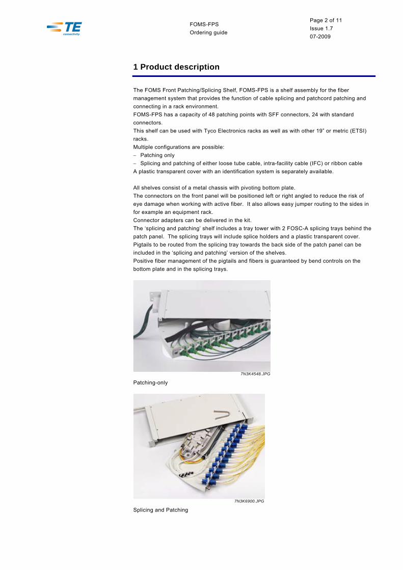
The FOMS Front Patching/Splicing Shelf, FOMS-FPS is a shelf assembly for the fiber management system that provides the function of cable splicing and patchcord patching and connecting in a rack environment. FOMS-FPS has a capacity of 48 patching points with SFF connectors, 24 with standard connectors. This shelf can be used with Tyco Electronics racks as well as with other 19” or metric (ETSI) racks. Multiple configurations are possible: − Patching only − Splicing and patching of either loose tube cable, intra-facility cable (IFC) or ribbon cable A plastic transparent cover with an identification system is separately available. All shelves consist of a metal chassis with pivoting bottom plate. The connectors on the front panel will be positioned left or right angled to reduce the risk of eye damage when working with active fiber. It also allows easy jumper routing to the sides in for example an equipment rack. Connector adapters can be delivered in the kit. The ‘splicing and patching’ shelf includes a tray tower with 2 FOSC-A splicing trays behind the patch panel. The splicing trays will include splice holders and a plastic transparent cover. Pigtails to be routed from the splicing tray towards the back side of the patch panel can be included in the ‘splicing and patching’ version of the shelves. Positive fiber management of the pigtails and fibers is guaranteed by bend controls on the bottom plate and in the splicing trays.
7N3K4548.JPG
Patching-only
7N3K6900.JPG
Splicing and Patching
FOMS-FPS Ordering guide
Page 3 of 11 Issue 1.7 07-2009
2 Ordering information
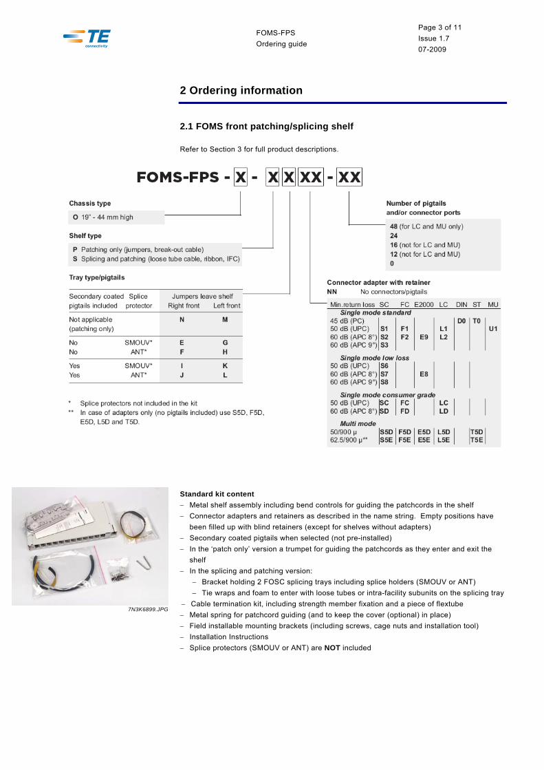
2.1 FOMS front patching/splicing shelf
Refer to Section 3 for full product descriptions.
Standard kit content − Metal shelf assembly including bend controls for guiding the patchcords in the shelf − Connector adapters and retainers as described in the name string. Empty positions have
been filled up with blind retainers (except for shelves without adapters) − Secondary coated pigtails when selected (not pre-installed) − In the ‘patch only’ version a trumpet for guiding the patchcords as they enter and exit the
shelf − In the splicing and patching version:
− Bracket holding 2 FOSC splicing trays including splice holders (SMOUV or ANT) − Tie wraps and foam to enter with loose tubes or intra-facility subunits on the splicing tray
− Cable termination kit, including strength member fixation and a piece of flextube − Metal spring for patchcord guiding (and to keep the cover (optional) in place) − Field installable mounting brackets (including screws, cage nuts and installation tool) − Installation Instructions − Splice protectors (SMOUV or ANT) are NOT included
7N3K6899.JPG

FOMS-FPS Ordering guide
Page 4 of 11 Issue 1.7 07-2009
2.2 Accessories
Name Qty/Pk Description
FOMS-FPS-O-COVER 1 pc Protective plastic transparent cover FIST-RET-05-50-S6080 50 pc Blind retainers FOMS-FPS-O-SPRING-5 5 pc Additional spring FOMS-FPS-O-TRUMPET 1 kit Additional trumpet FOMS-FPS-O-MB2-M 1 kit ETSI mounting brackets FIST-GS-FLEX-10-50 50 m Flexible tubing (internal ∅ 10 mm) FIST-TUBE-5MM-30 30 m Tubing, ∅ 5 mm FIST-GR-CTB100 1 kit Cable termination kit for max. 2 loose tube ribbon cables FIST-GR-CTB100-CC 1 kit Cable termination kit for max. 2 central core cables FIST-GR-TD-5MM 1 pc Tube divider 6 in/6 out SMOUV-1120-02-PK 100 pc 45 mm long heat-shrinkable splice protection sleeves 2.3 Tools
Name Qty/Pk Description
FACC-CAGE-NUT-TOOL 1 pc Cage nut installation tool FACC-ALLEN-KEY-5-350 1 pc Allen key, ∅ 5 mm, length 350 mm for back mounting of
shelves in rack
FOMS-FPS Ordering guide
Page 5 of 11 Issue 1.7 07-2009
3 Product guide
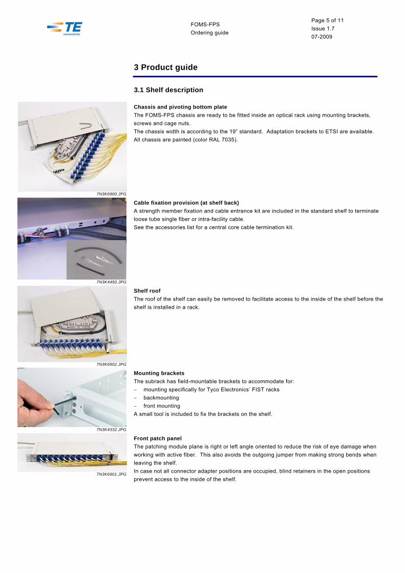
3.1 Shelf description
7N3K6900.JPG
Chassis and pivoting bottom plate The FOMS-FPS chassis are ready to be fitted inside an optical rack using mounting brackets, screws and cage nuts. The chassis width is according to the 19” standard. Adaptation brackets to ETSI are available. All chassis are painted (color RAL 7035).
7N3K4450.JPG
Cable fixation provision (at shelf back) A strength member fixation and cable entrance kit are included in the standard shelf to terminate loose tube single fiber or intra-facility cable. See the accessories list for a central core cable termination kit.
7N3K6902.JPG
Shelf roof The roof of the shelf can easily be removed to facilitate access to the inside of the shelf before the shelf is installed in a rack.
7N3K4332.JPG
Mounting brackets The subrack has field-mountable brackets to accommodate for: − mounting specifically for Tyco Electronics’ FIST racks − backmounting − front mounting A small tool is included to fix the brackets on the shelf.
7N3K6901.JPG
Front patch panel The patching module plane is right or left angle oriented to reduce the risk of eye damage when working with active fiber. This also avoids the outgoing jumper from making strong bends when leaving the shelf. In case not all connector adapter positions are occupied, blind retainers in the open positions prevent access to the inside of the shelf.

FOMS-FPS Ordering guide
Page 6 of 11 Issue 1.7 07-2009
7N3K4548.JPG
Patching-only configuration* Patchcords enter the shelf via a trumpet on the left or back side and are guided via bend controls towards the back of the patch panel. Patchcords connected at the front of the patch panel leave via a clip on the right side of the shelf. Connector adapters can be included in the kit. A hook-and-loop fastener tape prevents the patchcords from coming out once installed.
7N3K4453.JPG
Splicing and patching configuration* Loose tube cable or intra-facility cable (IFC) enters via the left or back side of the shelf and is guided towards the splicing trays. In case of loose tube cable and non-preconnectorized IFC, fibers are to be spliced to secondary coated pigtails in the splicing trays and then guided towards the backside of the patch panel. In case of preconnectorized IFC, overlength is stored in the splicing trays, offering the possibility to resplice damaged IFC to new pigtails. Patchcords connected at the front of the patch panel leave via a clip on the right side of the shelf. Secondary coated pigtails can be included in the kit. The tray tower can be pivoted slightly in case another shelf or equipment mounted on top should hinder access. Ribbon fibers always have to be de-ribbonized when entering the tray and have to be spliced to individual pigtails.
* Note: The above mentioned configurations describe the situation where patchcords leave the shelf at the right side. Patchcords can leave the shelf at the left side as well.
7N3K6908.JPG
Inlet trumpet A flexible trumpet at the side or back of the shelf protects incoming pigtails or jumpers.
3.2 Shelf dimensions
19” chassis standard Without cover With cover Width (with/without mounting brackets) 481 / 444 mm 481 / 444 mm Height HU-Height Units
44 mm (requires 1 19” HU)
44 mm (requires 1 19" HU)
Depth 215 mm 280 mm
Note: A HU is a “height unit”. Refer to rack documentation for more details.

FOMS-FPS Ordering guide
Page 7 of 11 Issue 1.7 07-2009
3.3 Shelf capacity
FOMS-FPS Splice & patch Patch only Number of FOSC A splicing trays 2 NA FOSC A splicing tray capacity − 250µ to 250µ 24 NA − 250µ to 900µ (a) 2 NA Patch panel capacity (std. connectors / SFF connectors) 24 / 48 SFF 24 / 48 SFF Pigtail length inside the shelf (from the splice till the back side of the patch panel)
1,5 m NA
Patchcord length inside the shelf – from the trumpet till the back side of the patch panel (b)
NA 0.50-0.90 m
Patchcord length inside the shelf – from the trumpet till the front side of the patch panel (b)
0.06-0.40 m 0.06-0.40 m
(a) In case more than 2 fibers are stored on a splicing tray, the 900µ pigtails must be stripped to 250µ (preferred transfer zone is indicated in section 3.3.1).
(b) This patchcord length is measured for the open shelf, to allow access after installation. 3.3.1 FOMS-FPS with small form factor connectors
Patch panel capacity: 48 SFF Splicing area capacity:
48 splices (250µ to 250µ) (24 splices per tray). In case of 900µ pigtails (semi-tight buffered), the 900µ buffer must be stripped to 250µ in the preferred transfer zone: see drawing underneath.
Restriction: When the intended capacity of the tray is 24, all fibers have to be installed on day 1. All pigtails are wrapped in a spiral tube. It is not possible to add pigtails at a later stage.
Preferred 900µ/250µ transfer zone
Behind this lip
Preferred 900µ/250µ transfer zone
Behind this lip
AUT18253.JPG
AUT18252.JPG

FOMS-FPS Ordering guide
Page 8 of 11 Issue 1.7 07-2009
3.3.2 Shelf support
panels (side/back panel)or door
shelf support (mounting profile)
rack frameor structure
Legend:
TYPE OF SHELF SUPPORT
1. Tyco Electronics rack with side ductETSI mounting profilesback mountingcapacity: 24 std. adapters
2. Open frame – no panels/doorsjust a shelf supportfront mountingcapacity: 24 std. adapters
3. Non Tyco Electronics rack600 mm wide, no side ductback mountingcapacity: 16 std. adapters
4. Non Tyco Electronics rack600 mm wide, no side ductfront mountingcapacity: 16 std. adapters

FOMS-FPS Ordering guide
Page 9 of 11 Issue 1.7 07-2009
3.4 Mounting options
BACK mounting 275.
1
211.
5
280
215
in Tyco Electronics rack (13.5 mm from back)
275.
1
13.5
280
13.5
FRONT mounting
63.6
275.
1
6528
0
Notes: − For easy entry and exit of cables and pigtails via the trumpets, a 100 mm free space (left or
right of the shelf) is recommended. − For back termination of cables a 40 mm free space (at the back of the shelf) is
recommended. − For side termination of cables a 160 mm free space (aside the shelf) is recommended.
FOMS-FPS Ordering guide
Page 10 of 11 Issue 1.7 07-2009
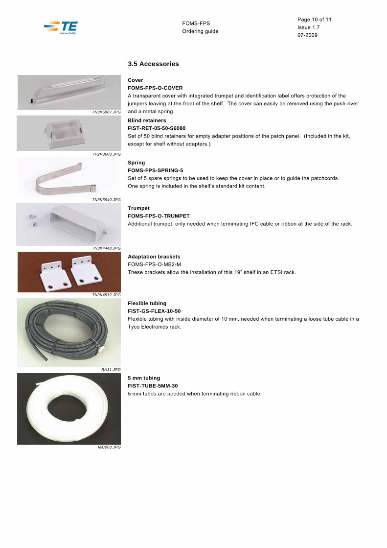
3.5 Accessories
7N3K6907.JPG
Cover FOMS-FPS-O-COVER A transparent cover with integrated trumpet and identification label offers protection of the jumpers leaving at the front of the shelf. The cover can easily be removed using the push-rivet and a metal spring.
7P2P3603.JPG
Blind retainers FIST-RET-05-50-S6080 Set of 50 blind retainers for empty adapter positions of the patch panel. (Included in the kit, except for shelf without adapters.)
7N3K6940.JPG
Spring FOMS-FPS-SPRING-5 Set of 5 spare springs to be used to keep the cover in place or to guide the patchcords. One spring is included in the shelf’s standard kit content.
7N3K4448.JPG
Trumpet FOMS-FPS-O-TRUMPET Additional trumpet, only needed when terminating IFC cable or ribbon at the side of the rack.
7N3K4512.JPG
Adaptation brackets FOMS-FPS-O-MB2-M These brackets allow the installation of this 19” shelf in an ETSI rack.
RA11.JPG
Flexible tubing FIST-GS-FLEX-10-50 Flexible tubing with inside diameter of 10 mm, needed when terminating a loose tube cable in a Tyco Electronics rack.
I&C003.JPG
5 mm tubing FIST-TUBE-5MM-30 5 mm tubes are needed when terminating ribbon cable.

FOMS-FPS Ordering guide
Page 11 of 11 Issue 1.7 07-2009
GCO2OG14.JPG
Cable termination ribbon loose tube cable FIST-GR-CTB100 Cable termination kit for max. 2 ribbon loose tube cable. Can be mounted next to the shelf. Up to 6 tubes of R12. Strength member fixation compatible with most types of strength members (1.5-5 mm Ø).
GCO2OG15.JPG
Cable termination central core cable FIST-GR-CTB100-CC Cable termination kit for max. 2 central core cables. Can be mounted next to the shelf. Strength member fixation (till 2.5 mm Ø).
7N3K1585.JPG
Tube divider for ribbon FIST-GR-TD-5MM Tube divider to be placed in the side duct of a rack. 5 tubes 5mm in – 5 tubes 5 mm out can be used to spread (ribbon) fibers over several tubes.
3.6 Tools
TO23.JPG
Cage nut tool FACC-CAGE-NUT-TOOL Tool to install cage nuts in the rack.
TO04.JPG
Long Allen key FACC-ALLEN-KEY-5-350 Allen key, diameter 5 mm, length 350 mm for back-mounting of shelves in rack.

TE Connectivity products deliver a competitive
advantage by meeting stringent demands for
performance and reliability.
Innovative TE Connectivity components and
systems are used in telecommunications,
electronics, transportation, infrastructure and
energy networks markets throughout the world.
OG/FOMS-FPS/1/07/09
TE (logo) and TE Connectivity are trademarks of the TE Connectivity group of companies and its licensors.
While TE Connectivity and its affiliates referenced herein have made every reasonable effort to ensure the accuracy of the information contained in this catalog, TE Connectivity cannot assure that this information is error free. For this reason, TE Connectivity does not make any representation or offer any guarantee that such information is accurate, correct, reliable or current. TE Connectivity reserves the right to make any adjustments to the information at any time. TE Connectivity expressly disclaims any implied warranty regarding the information contained herein, including, but not limited to, the implied warranties of merchantability or fitness for a particular purpose. TE Connectivity’ only obligations are those stated in TE Connectivity’ Standard Terms and Conditions of Sale. TE Connectivity will in no case be liable for any incidental, indirect or consequential damages arising from or in connection with, including, but not limited to, the sale, resale, use or misuse of its products. Users should rely on their own judgment to evaluate the suitability of a product for a certain purpose and test each product for its intended application.
Tyco Electronics Raychem bvba Diestsesteenweg 692 B-3010 Kessel-Lo, Belgium Tel.: 32-16-351 011 Fax: 32-16-351 697 www.te.com www.telecomnetworks.com