ordinance no. 18 2 8 45 the people of the city of los …
TRANSCRIPT
ORDINANCE NO. __ 18_2_8_45An ordinance amending Article 1.5, Chapter IX of the Los Angeles Municipal
Code to reflect local administrative changes and incorporate by reference portions ofthe 2013 Edition of the California Residential Code (CRC).
THE PEOPLE OF THE CITY OF LOS ANGELESDO ORDAIN AS FOLLOWS:
Section 1. Section 91.5.101 of the Los Angeles Municipal Code is amended toread as follows:
SEC. 91.5.101. TITLE.
Article 1.5 of Chapter IX of the Los Angeles Municipal Code shall collectively beknown as the Los Angeles Residential Code or LARC. The provisions of the LARC forone- and two-family dwellings shall apply to the construction, alteration, movement,enlargement, replacement, repair, equipment, use and occupancy, location,maintenance, removal and demolition of detached one- and two-family dwellings,efficiency dwelling units, and townhouses not more than three stories above gradeplane in height with a separate means of egress and their accessory structures. Inaddition to the LARC, Chapters 1, 11A, 11B, 17, 34,63,67,70,71,72,81,89,92,93and 96, and Section 3109 of the Los Angeles Building Code or LASC shall also beapplicable to one- and two-family dwellings, efficiency dwelling units, and townhousesunless stated otherwise. Wherever the word "Code" is used in this Article, it shall meanthe Los Angeles Building Code (LABC).
The LABC and the LARC adopt by reference portions of the 2013 CaliforniaBuilding Code (CBC) or the 2013 California Residential Code (CRC) respectively.
EXCEPTION:
1. Live/work units complying with the requirements of Section419 of the California Building Code shall be permitted to be built as one-and two-family dwellings or townhouses. Fire suppression required bySection 419.5 of the Californ ia Building Code when constructed under theCalifornia Residential Code for one- and two-family dwellings shallconform to Section 903.3.1.3 of the California Building Code.
2. Owner-occupied lodging houses with five or fewerguestrooms shall be permitted to be built in accordance with the CaliforniaResidential Code for one- and two-family dwellings when equipped with afire sprinkler system in accordance with Section R313.
1

Sec. 2. Section 91.5.301.1.4 of the Los Angeles Municipal Code is amended toread as follows:
91.5.301.1.4. Seismic Design Provisions For Buildings Constructed On Or IntoSlopes Steeper Than One Unit Vertical In Three Units Horizontal (33.3 PercentSlope). The design and construction of new buildings and additions to existingbuildings when constructed on or into slopes steeper than one unit vertical in three unitshorizontal (33.3 percent slope) shall comply with Section 91.1613.8 of the Los AngelesMunicipal Code.
Sec. 3. Section 91.5.301.2.2.3.5.1 of the Los Angeles Municipal Code is deletedin its entirety.
Sec. 4. Section 91.5.301.2.2.3.8 of the Los Angeles Municipal Code is added toread as follows:
91.5.301.2.2.3.8. Anchorage of Mechanical, Electrical, or Plumbing Componentsand Equipment. Mechanical, electrical, or plumbing components and equipment shallbe anchored to the structure. Anchorage of the components and equipment shall bedesigned to resist loads in accordance with the International Building Code and ASCE7, except where the component is positively attached to the structure and flexibleconnections are provided between the component and associated ductwork, piping, andconduit; and either:
1. The component weighs 400 Ib (1,780 N) or less and has a center ofmass located 4 ft (1.22 m) or less above the supporting structure; or
2. The component weighs 20 Ib (89N) or less or, in the case of adistributed system, 5 Iblft (73 N/m) or less.
Sec. 5. The first paragraph of Section 91.5.401.1 of the Los Angeles MunicipalCode is amended to read as follows:
91.5.401.1. Application. The provisions of this Division shall control the design andconstruction of the foundation and foundation spaces for all buildings. In addition to theprovisions of this Division, the design and construction of foundations in flood hazardareas as established by Table 91.5.301.2(1) shall meet the provisions of Section R322.Wood foundations shall be designed and installed in accordance with AF&PA PWF.
Sec. 6. Section 91.5.501.1 of the Los Angeles Municipal Code is amended toread as follows:
91.5.501.1. Application. The provisions of this Division shall control the design andconstruction of the floors for all buildings including the floors of attic spaces used tohouse mechanical or plumbing fixtures and equipment. Mechanical or plumbing fixtures
2

and equipment shall be attached (or anchored) to the structure in accordance withSection 91.5.301.2.2.3.8.
Sec. 7. Section 91.5.600 of the Los Angeles Municipal Code is amended to readas follows:SEC. 91.5.600. BASIC PROVISIONS.
Chapter 6 of the CRC is hereby adopted by reference with the exceptions,modifications and additions set forth below. Additionally, Section R602.10.9.1 from the2013 California Building Code is not adopted.
Sec. 8. Table 91.5.602.3(1) of the Los Angeles Municipal Code is amended toread as follows:
TABLE 91.5.602.3(1)
Fastener Schedule For Structural Members
DESCRIPTION OF BUILDING NUMBER AND SPACING OFITEM TYPE OFELEMENTS FASTENER a, b, CFASTENERS
Roof
1 Blocking between joists or rafters 3-8d (21/2" x 0.113") -to top plate, toe nail
2 Ceiling joists to plate, toe nail 3-8d (21h" x 0.113") -Ceiling joists not attached to
3 parallel rafter, laps over partitions, 3-10d -face nail
4 Collar tie to rafter, face nail or 3-10d (3" x 0.128")11// x 20 gauge ridge strap -
3-16d box nails 2 toe nails on one side(31// x 0.135") orRafter or roof truss to plate, toe and 1 toe nail on5 3-10d commonnail nails opposite sideof each
(3" x 0.148") rafter or truss)
4-16d (31/2" x
6 Roof rafters to ridge, valley or hip 0.13511) -rafters: toe nail face nail 3-16d (31/2" x
0.135")Wall
7 Built-up studs-face nail 10d (3" x 0.128") 24" o.c.
8 Abutting studs at intersecting wall 16d (31/2" x 0.135") 12" o.c.corners, face nail
9 Built-up header, two pieces with 16d (31/z" x 0.135") 16" o.c. along each edge1/z" spacer
3

10 Continued header, two pieces 16d (31/{ x 0.135") 16" o.c. along each edge
11 Continuous header to stud, toe 4-Sd (21/2" x 0.113")nail -
12 Double studs, face nail 10d (3" x 0.12S") 24" o.C.13 Double top plates, face nail 10d (3" x 0.12S") 24" o.c.
Double top plates, minimum 24- S-16d (31/2" x14 inch offset of end joints, face nail 0.135") -in lapped area
15 Sale plate to joist or blocking, face 16d (31/2" x 0.135") 16" o.c.nail
16 Sole plate to joist or blocking at 3-16d (31/z" x 16" o.c.braced wall panels 0.135")3-Sd (21/2" x 0.113")
17 Stud to sole plate, toe nail or 2-16d (31/{ x -
0.135")
1S Top or sole plate to stud, end nail 2-16d (31/2" x -0.135")
19 Top plates, laps at corners and 2-10d (3" x 0.12S") -intersections, face nail
20 1" brace to each stud and plate, 2-Sd (21/2" x 0.113") -face nail 2 staples 1 3/4" x
21 1" x 6" sheathing to each bearing, 2-Sd (21/2" x 0.113") -face nail 2 staples 1 3h"
22 1" x S" sheathing to each bearing, 2-Sd (21/2" x 0.113") -
face nail 3 staples 1 314
23 Wider than 1" x S" sheathing to 3-Sd (21/{ x 0.113") -each bearing, face nail 4 staples 13//Floor
24 Joist to sill or girder, toe nail 3-Sd (21/2" x 0.113'/) -
25 Rim joist to top plate, toe nail (roof Sd (21/2" x 0.11311) 6" o.c.applications also)
26 Rim joist or blocking to sill plate, Sd (21/2" x 0.113U) 6" o.c.toe nail
27 1" x 6'1 subfloor or less to each 2-Sd (21/2" x 0.113")joist, face nail 2 staples 13/4" -
2S 2" subfloor to joist or girder, blind 2-16d (31/2" x -and face nail 0.135")
29 2" planks (plank & beam - floor & 2-16d (31/211 xat each bearingroof) 0.13511
)
4

Nail each layer asfollows: 32" o.c. at top
30 Built-up girders and beams, 2-inch 10d (3" x 0.128") and bottom andlumber layers staggered.
Two nails at ends and ateach splice.
31 Ledger strip supporting joists or 3-16d (31/2" x At each joist or rafterrafters 0.135")
TABLE 91.5.602.3(1)
Continued Fastener Schedule For Structural Members
DESCRIPTION OF SPACING OF FASTENERS
ITEM BUILDING DESCRIPTION OF IntermediateFASTENERb, c, e, k Edges
MATERIALS (inches)'supports" e
(inches)Wood structural panels, subfloor, roof and interior wall sheathing to framing and
particleboard wall sheathing to framing6d common (2" x
3/" Y:;"0.11 ~") nail (subfloor
32 8 - 2 wall)' 6 12g
8d common (21/2" x0.131") nail (roof)'
33 19/" 1" 8d common nail (21It 6 12932 - x 0.131")10d common (3" x
34 111a"-11/4" 0.148") nail or 6 128d (21h" x 0.131 ")deformed nail
Other wall sheathlnq"
1/2" structural11/2" galvanizedroofing nail, 7/16"
35 cellulosic crown or 1" crown 3 6fiberboard sheathing staple 16 ga., 11/4"
long
25/32" structural13// galvanizedroofing nail, 7/16"
36 cellulosic crown or 1" crown 3 6fiberboard sheathing staple 16 ga., 11/2"
long
5

11/2" galvanized
Yz" gypsum roofing nail; staple37 sheathing" galvanized, 7 7
11/" long' 1112 ,4screws, Type W or S13// galvanized
518" gypsum roofing nail; staple38 sheathinq" galvanized, 7 7
151 " long' 15/ "8 ,8screws, Type W or S
Wood structural panels, combination subfloor underlayment to framing6d deformed (2" x
39 3/4" and less 0.120") nail or 6 128d common (21/2" x0.131") nail8d common (21h" x
40 7/8" - 1" 0.131") nail or 6 128d deformed (21hI! x0.120") nail10d common (3" x
41 11/8"-11/4" 0.148") nail or 6 128d deformed (21/2" x0.120") nail
For SI: 1 inch = 25.4 mm, 1 foot = 304.8 mm, 1 mile per hour = 0.447 m/s; 1 Ksi = 6.895 MPa.a. All nails are smooth-common, box or deformed shanks except where otherwise stated. Nails used forframing and sheathing connections shall have minimum average bending yield strengths as shown: 80 ksifor shank diameter of 0.192 inch (20d common nail), 90 ksi for shank diameters larger than 0.142 inch butnot larger than 0.177 inch, and 100 ksi for shank diameters of 0.142 inch or less.b. Staples are 16 gauge wire and have a minimum 7/16-inch on diameter crown width.c. Nails shall be spaced at not more than 6 inches on center at all supports where spans are 48 inches orgreater.d. Four-foot by 8-foot or 4-foot by 9-foot panels shall be applied vertically.e. Spacing offasteners not included in this table shall be based on Table 91.5.602.3(2).f. For regions having basic wind speed of 110 mph or greater, 8d deformed (21/2" x 0.120) nails shall beused for attaching plywood and wood structural panel roof sheathing to framing within minimum 48-inchdistance from gable end wails, if mean roof height is more than 25 feet, up to 35 feet maximum.g. For regions having basic wind speed of 100 mph or less, nails for attaching wood structural panel roofsheathing to gable end wall framing shall be spaced 6 inches on center. When basic wind speed isgreater than 100 mph, nails for attaching panel roof sheathing to intermediate supports shall be spaced 6inches on center for minimum 48-inch distance from ridges, eaves and gable end walls; and 4 inches oncenter to gable end wall framing.h. Gypsum sheathing shall conform to ASTM C 1396 and shall be installed in accordance with GA 253.Fiberboard sheathing shall conform to ASTM C 208.
6

i. Spacing of fasteners on floor sheathing panel edges applies to panel edges supported by framingmembers and required blocking and at all floor perimeters only. Spacing of fasteners on roof sheathingpanel edges applies to panel edges supported by framing members and required blocking. Blocking ofroof or floor sheathing panel edges perpendicular to the framing members need not be provided exceptas required by other provisions of this code. Floor perimeter shall be supported by framing members orsolid blocking.j. Where a rafter is fastened to an adjacent parallel ceiling joist in accordance with this schedule, providetwo toe nails on one side of the rafter and toe nails from the ceiling joist to top plate in accordance withthis schedule. The toe nail on the opposite side of the rafter shall not be required.
k. Use of Staples in braced wall panels shall be prohibited in Seismic Design Category Do. D1, or O2.
7

Sec. 9. Table 91.5.602.3(2) of the Los Angeles Municipal Code is amended toread as follows:
TABLE 91.5.602.3(2)Alternate Attachments To Table 91.5.602.3(1)
NOMINAL DESCRIPTIONa, b OF SPACINGc OF FASTENERSMATERIAL FASTENER AND LENGTH Intermediate
THICKNESS (inches)Edges supports
(inches) (inches) (inches)Wood structural panels subfloor, roof" and wall sheathing to framing and
particleboard wall sheathing to framing'
Up to % 0.097 - 0.099 Nail 21/4 3 6
19/32and 5/80.113 Nail 2 3 6
0.097 - 0.099 Nail 21/4 4 8
23/32and % 0.097 - 0.099 Nail 21/4 4 8
10.113 Nail 21/4 3 6
0.097 - 0.099 Nail 21/2 4 8NOMINAL DESCRIPTIONa,b OF FASTENER SPACINGc OF FASTENERSMATERIAL AND LENGTH Edges Body of panel"THICKNESS
(inches)(inches) (inches) (inches)
Floor underlayment; plywood-hard board-particleboard'Plywood
11/4 ring or screw shank nail-
X and 5/16minimum 3 6
121tz gao (0.099") shank diameterStaple 18 ga., 7/8, 3/16crown width 2 5
11/ 3/ 15/ d Y.11/4 ring or screw shank nail-
32, 8, 32, an 2 minimum 6 Se12% gao (0.099") shank diameter
8

11/2 ring or screw shank nail-minimum
6 8191 5/ 231 d 3132, 8, 32an 4121/2gao (0.099") shank diameter
Staple 16 gao 11/2 6 8Hardboard'
11/2 long ring-grooved underlayment 6 6nail0.200 4d cement-coated sinker nail 6 6
Staple 18 ga., 7/8 long (plastic 3 6coated)Particleboard
4d ring-grooved 3 6%
underlayment nailStaple 18 ga., 7/8 long, 3/16 3 6crown
6d ring-grooved 6 103fe underlayment nail
Staple 16 ga., 11/8 long, 318 3 6crown6d ring-grooved 6 10
1h 5/8underlayment nail
Staple 16 ga., 15/8 long, 318 3 6crown
For SI: 1 inch= 25.4 rnm.a. Nail is a general description and may be T-head, modified round head or round head.b. Staples shall have a minimum crown width of 7/winch on diameter except as noted. Use of staples inroof, floor, subfloor, and braced wall panels shall be prohibited in Seismic Design Category Do, D1, or D2.
c. Nails or staples shall be spaced at not more than 6 inches on center at all supports where spans are 48inches or greater. Nails or staples shall be spaced at not more than 12 inches on center at intermediatesupports for floors.d. Fasteners shall be placed in a grid pattern throughout the body of the panel.e. For 5-ply panels, intermediate nails shall be spaced not more than 12 inches on center each way.f. Hardboard underlayment shall conform to CPNANSI A135.4.g. Specified alternate attachments for roof sheathing shall be permitted for wind speeds less than 100 mph.Fasteners attaching wood structural panel roof sheathing to gable end wall framing shall be installed usingthe spacing listed for panel edges.
9

Sec. 10. Section 91.5.602.3.2 of the Los Angeles Municipal Code is added toread as follows.
91.5.602.3.2. Top Plate. Wood stud walls shall be capped with a double top plateinstalled to provide overlapping at corners and intersections with bearing partitions. Endjoints in top plates shall be offset at least 24 inches (610 mm). Joints in plates need notoccur over studs. Plates shall be not less than 2 inches (51 mm) nominal thickness andhave a width at least equal to the width of the studs.
EXCEPTION: In other than Seismic Design Category Do, 01 or O2, asingle top plate may be installed in stud walls, provided the plate is adequatelytied at joints, corners and interesting walls by a minimum 3 inch by 6 inch by0.036 inch thick (76 mm by 152 mm by 0.914 mm) galvanized steel plate that isnailed to each wall or segment of wall by six 8d nails on each side, provided therafters or joists are centered over the studs with a tolerance of no more than 1inch (25 mm). The top plate may be omitted over lintels that are adequately tiedto adjacent wall sections with steel plates or equivalent as previously described.
Sec. 11. Table 91.5.602.10.1.2(2) of the Los Angeles Municipal Code is deletedin its entirety.
Sec. 12. Table 91.5.602.10.2 of the Los Angeles Municipal Code is deleted in itsentirety.
Sec. 13. Section 91.5.602.10.2.3 of the Los Angeles Municipal Code is added toread as follows:
91.5.602.10.2.3. Minimum Number of Braced Wall Panels. Braced wall lines with alength of 16 feet (4877 mm) or less shall have a minimum of two braced wall panels ofany length or one braced wall panel equal to 48 inches (1219 mm) or more. Bracedwall lines greater than 16 feet (4877 mm) shall have a minimum of two braced wallpanels. No braced wall panel shall be less than 48 inches in length in Seismic DesignCategory Do, 01, or O2.
10

Sec. 14. Figure 91.5.602.10.3.2 of the Los Angeles Municipal Code is amendedto read as follows:
CIIU
'-'t.2m
PANF-LMUST 8[;},TT,~.CHr;DTO CmKRETE fOOTING ORCONCRElE F G',lf,JOATIONW.:',LL CONTIIIUOUS O\'EFieR,',CED W~u, LlI'lE
?ANEllEt-lG1H PERTA5LE 91,S.6!l"2.10.5
;~=i~.-:'=~=:;:=:::'!:'::::=..~.:~'"~=-==:'=::-C-:=jJ
~HN. 15/32:"WOODSJRUCT{JAAt PANEL8HEATiilNGON ONE FACE
~;N ) :.: ~ rR~ Wt.(<}Wll. --."-~_~DO l.JelE STI)O!;) REQ'JII~ED "',
-..... ,,-
(:;~:.H()LD.I)O\\,I·J OR ("I SYR;,!',n'p& ~i
ANCH8RS PER TAGLE R:)02. iO.0.1 IOI~~~\..OF E"'CH SH·)\,·.'N FOR CL~R1f n \'"STR<.P-TWE.II hCIIOr..."S SHM.l OG v \,PERl'AITTEC' Te, 8EATTACHED OVER '\1 HE MKI DSlRl,J(:Tuh,,'l PAJJf,l \
\\
r:n 117" OIAI.l E IE r, ;;rjCI-iOR~OL rs LbC"AH:D Il[;PllSGt'J6' "'ND 1z: 0 f E"'CH <:t·D OFTfir; ~~r,;GI.lr,I;T
,.~....,~.~~...,----
For S1: 1 inch = 25.4 mm.
FCR P~.NEl SPU co: ilF f·EFDED)~OJO!t~NG P:•.tlELEOGES ~!ALL 1,IEErCl'/ERMm BE FfoSTH:EO TO COf,HAONrRl"litr'JG
80 COk'if.'lOIJ OR I),\l:" eol. W"IL'~ (1'!)O.CAT I"AN[;L~OG~S. FOR ~1I-JG.Li:SHlR:111!'lD@·r O.C:. r',1,f~El EDGESFORTH.'> rlRH OF 2STORIE9
$TU[)S lINCER HE".DER':"S RE<lUIRED
so G,J~U;lotJOR G"l',' l~OK"'I1(3·@'''-o C .... T INTERI')R SUPP6 RTS
MilL REl'NFO RC'ING OF FOUNDl\ llON,ONE 1M BAR TOP A~1DBOTTOM. LAPS".RG~4' ~HNlMUM.
MINIMUM FOOmrG :::IZ.EUNDEROPENlt~G IS T2' X 12",
FIGURE 91.5.602.10.3.2METHOD ABW - ALTERNATE BRACED WALL PANEL
11

Sec. 15. Table 91.5.602.10.3(3) of the Los Angeles Municipal Code is added toread as follows:
TABLE 91.5.602.10.3(3)Bracing Requirements Based On Seismic Design Cateaorv
• SOIL CLASS Db• WALL HEIGHT = 10 FEET• 10 PSF FLOOR DEAD LOAD• 15 PSF ROOF/CEILING DEAD LOAD• BRACED WALL LINE SPACING S 25FEET
MINIMUM TOTAL LENGTH (FEET) OFBRACED WALL PANELS
REQUIRED ALONG EACH BRACEDWALL LINEa
SeismicDesign
CategoryStory Location
Braced
WL
"all Method Methodme us- GBe
Length(feet)
MethodsDWB,SFB,PBS,PCpe,HPS,CS~
SFBd
MethodsMethod CS-
WSP WSP,CS-G
C(town houses
only)
d.: ,~
10 2.5 2.520 5.0 5.030 7.5 7.540 10.0 10.050 12.5 12.510 NP 4.520 NP 9.030 NP 13.540 NP 18.050 NP 22.510 NP 6.020 NP 12.030 NP 18.040 NP 24.050 NP 30.0
2.55.07.510.012.54.59.013.518.022.56.012.018.024.030.0
1.6 1.43.2 2.74.8 4.16.4 5.48.0 6.83.0 2.66.0 5.19.0 7.712.0 10.215.0 12.84.5 3.89.0 7.713.5 11.518.0 15.322.5 19.1
12

10 NP 5.6 5.6 1.8 1.6
.~20 NP 11.0 11.0 3.6 3.1
@ 30 NP 16.6 16.6 5.4 4.6~. 40 NP 22.0 22.0 7.2 6.150 NP 27.6 27.6 9.0 7.710 NP NP NP 3.8 3.2
~
20 NP NP NP 7.5 6.4Do
~
30 NP NP NP 11.3 9.640 NP NP NP 15.0 12.850 NP NP NP 18.8 16.010 NP NP NP 5.3 4.5
~
20 NP NP NP 10.5 9.030 NP NP NP 15.8 13.440 NP NP NP 21.0 17.9
.,_ .... ',-.
50 NP NP NP 26.3 22.3(contmued)
TABLE 91.5.602.10.3(3)
Continued Bracing Requirements Based On Seismic Design Category
.. SOIL CLASS Db
..WALL HEIGHT = 10 FEET MINIMUM TOTAL LENGTH (FEET) OF
.. 10 PSF FLOOR DEAD LOAD BRACED WALL PANELS• 15 PSF ROOF/CEILING DEAD LOAD REQUIRED ALONG EACH BRACED~BRACED WALL LINE SPACING :S 25 WALL LINEaFEET
Methods
Braced DWB,
Seismic Wall SFB, Methods
Design Story Location Line Method Method PBS, Method CS-LlBc GBe PCpe WSP WSP,Category Length ,
HPS, CS-G(feet) CS-SFBd
D1 10 NP 6.0 6.0 2.0 1.7
~
20 NP 12.0 12.0 4.0 3.4
~
........ _,',.
30 NP 18.0 18.0 6.0 5.1@................•
40 NP 24.0 24.0 8.0 6.8
13

50 NP 30.0 30.0 10.0 8.5
~ .. iE8
A...............•.~Ei~
1020304050102030
NPNPNPNPNPNPNPNP
NPNPNPNPNPNPNPNP
NPNPNPNPNPNPNPNP
4.59.013.518.022.56.012.018.0
3.87.711.515.319.15.110.215.3
40501020304050102030405010203040501020304050
NPNPNPNPNPNPNPNPNPNPNPNPNPNPNPNPNPNPNPNPNPNP
8.016.024.032.040.0
NPNP
NPNPNPNPNPNPNPNPNPNPNPNPNPNPNP
NPNP8.016.024.032.040.0NPNPNPNPNPNPNPNPNPNPNPNPNPNPNP
24.030.02.55.07.510.012.55.511.016.522.027.5
7.515.022.530.037.5
NPNPNPNPNP
20.425.52.14.36.48.510.64.79.414.018.723.4NPNPNPNPNP6.412.819.125.531.9
Cripple wall belowone- or two-story
dwelling
For SI: 1 inch= 25.4 mm, 1 footA "" 305 rnrn, 1 pound per square foot"" 0.0479 kPa.a. Linear interpolation shall be permitted.b. Wall bracing lengths are based on a soil site class "D."A Interpolation of bracing length between the
SdSvalues associated with the Seismic Design Categories shall be permitted when a site-specific Sds
value is determined in accordance with Section 1613.3 of the International Building Code.c. Method UB shall have gypsum board fastened to at least one side with nails or screws per Table
R602.3(1) for exterior sheathing or Table R702.3.5 for interior gypsum board. Spacing of fasteners at
14
panel edges shall not exceed 8 inches.d. Method CS-SFB applies in SDC Conly.
e. Methods GB and PCP braced wall panel h/w ratio shall not exceed 1:1 in SOC 00, 01, and O2.
Methods OWB, SFB, PBS, and HPS are not permitted in SOC 00,01, and O2.
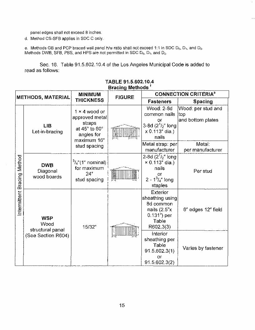
Sec. 16. Table 91.5.602.10.4 of the Los Angeles Municipal Code is added toread as follows:
racing e o s
METHODS, MATERIAL MINIMUM FIGURECONNECTION CRITERIA a
THICKNESS Fasteners Spacing
1 x 4 wood or Wood: 2-8d Wood: per stud and
approved metalcommon nails top
or and bottom platesLIB straps
~rrmlil"lIlillvifr1J3-8d (21/2" long
at 45° to 600
Let-in-bracing angles forx 0.113" dia.)
maximum 16" I"'-! 1'-' •.•\ nails
stud spacing Metal strap: per Metal:manufacturer per manufacturer
-0 2-8d (21/2" long03//(1" nominal).c x 0.1131
' dia.)...... DWBQ)for maximum >'~f~rll'li'li~HI nails:2: Diagonal Per stud
0)
wood boards 24" orcstud spacing 2 - 13// long'[5 ~'~"I .~'·I
~ staplesen....... ExteriorcQ) sheathing using~E 8d common'-Q) nails (2.5"x 6" edges 12" field.......c 0.131") per- WSP
Wood "rDrTable
structural panel 15/32" R602.3(3)
(See Section R604) Interior;-........ !-......i
sheathing perTable Varies by fastener91.5.602.3(1 )
or91.5.602.3(2)
TABLE 91.5.602.10.4B M th d f
15

BV-WSP e 4" at panel edgesWood Structural 8d common 12"at intermediate
Panels with Stone 15/32" See Figure (21/z" x 0.131) supports 4"at bracedor Masonry Veneer R602.10.6.5 nails wall panel end posts
(See SectionR602.10.6.5)
11/2" long x0.12" dia. (for
1/z" thicksheathing) 13//
long x 0.12"
SFB 1/2" or 25/32" for dia.(for 25/3z" thick 3" edges 6" field
Structural maximum 16" .-",:' I;
sheathing):':'.": ',' .. :
fiberboard sheathing stud spacing':";' '..". ,
" ,- .',... . , ~ galvanized1----1 1--"
roofing nails or8d common(21/2" long x0.131" dia.)
nailsNails or screws For all braced wall
per Table panel locations: 7"91.5.602.3(1 ) edges (including top
for exterior and bottom plates) T'GB
1/z" -.~~'--"~'~'"--~" locations fieldGypsum board lillll! 111<ilj Nails or screws
", ..... ",---·1 per TableR702.3.5 for
interiorlocations
For 3/" 6d8 ,common(2" long x
PBS3/8" or 1/z" for 0.113" dia.)
Particleboard "JiiIJ nailssheathing maximum 16 For 1/" 8d 3" edges 6" field
stud spacing 2 ,(See Section R605) common
(21/2" long x0,131" dia.)
nails
16

PCP See Section 11/z" long, 11 6"o.c. allR703.6 for llii!rGL 71 "d' on
Portland gage, 16 ra. framingmaximum 16 head nails
cement plaster stud spacingmembers
,.......-l 1--1
0.092" dia., 0.22511
dia. head nailsHPS 71 " for with length to16
JifI 4" edges 8"Hardboard maximum 16" accommodate
panel siding stud spacing 11/z" field
penetration intostuds
ABW See Section SeeAlternate 15/32" pfill®lll Section
braced wall auuuun ,J R602.10.6.1 R602.10.6.1, " rr
TABLE 91.5.602.10.4Continued Bracing Methods f
Interiorsheathing
perTable
91.5.602.3(1 )or
91.5.602.3(2)
Varies byfastener
ContinuousSheathingMethods
CS-WSPContinuously sheathedwood structuralA panel
15/32"
Exteriorsheathing
perTable
R602.3(3)
6" edges 12"field
17
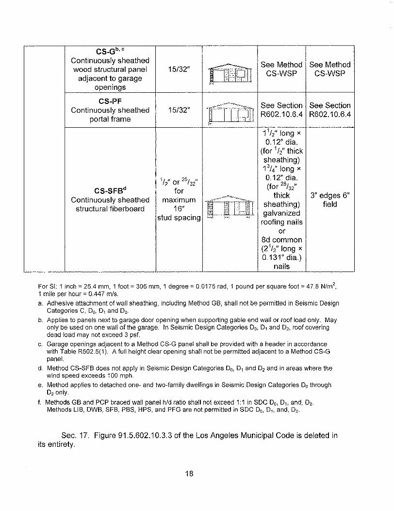
CS_Gb,cContinuously sheathedwood structural panel
adjacent to garageopenings
See Method See MethodCS-WSP CS-WSP
CS-PFContinuously sheathed
portal frame
CS-SFBdContinuously sheathed
structural fiberboard
15/32/1
15/32" See Section See SectionR602.10.6.4 R602.10.6.4
11/2" long x
0.12/1dia.(for 1/2/1 thicksheathing)13/4" long x0.12" dia.(for 25h2"
thicksheathing)galvanized
roofing nailsor
8d common(21/2" long x0.131/1dia.)
nails
311 edges 6"field
1/2" or 25132"
formaximum
16"stud spacing
For SI: 1 inch= 25.4 mm, 1 foot::: 305 mm, 1 deqree= 0.0175 rad, 1 pound per square foot= 47.8 N/m2,1 mile per hour= 0.447 m/s.a. Adhesive attachment of wall sheathing, including Method GB, shall not be permitted in Seismic Design
Categories C, Do, D1 and O2,
b. Applies to panels next to garage door opening when supporting gable end wall or roof load only. Mayonly be used on one wall of the garage. In Seismic Design Categories Do, D1 and O2, roof coveringdead load may not exceed 3 psf.
c. Garage openings adjacent to a Method CS-G panel shall be provided with a header in accordancewith Table R502.5(1). A full height clear opening shall not be permitted adjacent to a Method CS-Gpanel.
d. Method CS-SFB does not apply in Seismic Design Categories Do, D1 and O2 and in areas where thewind speed exceeds 100 mph.
e. Method applies to detached one- and two-family dwellings in Seismic Design Categories Do throughD2 only.
f. Methods GB and PCP braced wall panel hId ratio shall not exceed 1:1 in SOC Do, 01, and, D2.
Methods LIB, DWB, SFB, PBS, HPS, and PFG are not permitted in SOC Do, D1. and, O2.
Sec. 17. Figure 91.5.602.10.3.3 of the Los Angeles Municipal Code is deleted inits entirety.
18

Sec. 18. Figure 91.5.602.10.6.2 of the Los Angeles Municipal Code is added toread as follows:
'1!II
r-A-,rfN.-S1i-EATHHlGTf.i H~,!Dr:Ri..'liTU ik~C.OMI/;·Oi'}' tm G/ILVMHZJ::D so;.; 1I,'\il~ In $" OBIOPATTERK AS suO\"rn
;; ":'!'=J:,Tt.!-.,tHlPPLAT!: 1'0H~·;',UEI~ ~/o'rrH'tVIORCW:!:iOF'I6OSlUKt:P..I'it.ll!i: L'f}' o.c. TYP,
l·lf:.~E f~ TO .JAtK-STIJ0 ::;:rri,':'p e en 1.;.,Oi..sp.~n,HI,6.~ ON 60TH $1D:S Of' C~E:~\'H:GOPPrJS!l: sm~,Df SHt:/~1'j-:!U c-
MTN. o-OUBLE 2X~ FAAMJN-G cove RED- '..Villi M::N.15!32" THICK WOOD $TRUCTUAAt PAN EL SHEATH'NGWem 3d COMMON OR GALVANIZED 60X NAiLS AT s:C.C. iN ALL FRAM~!-JG !!i-TUOS, 6LOCK~r~Gt :..r·~D 5ILLS": TYP
~~-.~r....1!N.1S/32" WOOD~'TnUC1URAt PAN!!.$Ht.:,\ 1H!N(j
tJm. j2}.!j.:.t~C t..b ·:;",1i~/jp·-ryp-:. IWLO·U cwus(::I.~ff!:nn!:n trOT:') (',mH~Rr7r:- .4lm !1,;1.HB'l !~n::fR.~lIIHG)
,m: ";""0".'_ MIN, 1~£mfOACING or' f01.JNDAflON. ONE iN &t'J~,j,'" / \ lOP AND BOHOM orr OOTING. lAP OMS 2,1"
-~L--'~~'~~~~~~~~~~=~~~~'E~~~~~~~i~~~\ '-- !.HNfMUM f0011NG 51<t'Jtm~R OPENINGS IS
\ 12' X 11"
\--1J~~L('H5~&-tHNIlt'TEf'. ~':J;C!-:-(Hi 50Li' lN5TJi.LldJPt:::~RoJOS,I.6· V"l1TH2·::<~· x ::.lIe" r1.:I..T:ey~........S'--l~1't
FRONT ELEVATION SECTION
FIGURE 91.5.602.10.6.2METHOD PFH - PORTAL FRAME WITH HOLD-DOWNS
AT GARAGE DOOR OPENINGS
Sec. 19. Section 91.5.602.10.3.3 of the Los Angeles Municipal Code is deletedin its entirety.
Sec. 20. Table 91.5.602.10.4.1 of the Los Angeles Municipal Code is deleted inits entirety.
Sec, 21. Figure 91.5.602.10.4.1.1 of the Los Angeles Municipal Code is deletedin its entirety.
19

Sec. 22. Table 91.5.602.10.5 of the Los Angeles Municipal Code is added toread as follows:
TABLE 91.5.602.10.5
Minimum Length Of Braced Wall Panels
MINIMUM LENGTHa
METHOD(inches) CONTRIBUTING
Wall Height LENGTH(See Table R602.10.4)9 10 11 12 (inches)
8 feet feet feet feet feetDWB, WSP, SFB, PBS, PCP, HPS, BV- 48 48 48 53 58 Actual"WSP
Double sided =
GB 48 48 48 53 58 ActualSingle sided =0.5 x Actual
LIB 55 62 69 NP NP Actual"SOC A, Band C,
wind speed < 110 28 32 34 38 42
ABWmph
48SOC Do, 01 and O2,
wind speed < 110 32 32 34 NP NPmph
Supporting roof only 24 24 24 24c 24c 48PFH Supporting one story 27c 29c
and roof 24 24 24 48
PFG 24 27 30 33d 36d 1.5 x Actual"CS-G 24 27 30 33 36 Actual"CS-PF 24 24 24 24e 24e Actual"
20

Adjacent clearopening height
(inches)::;64 24 27 30 33 3668 26 27 30 33 3672 27 27 30 33 3676 30 29 30 33 3680 32 30 30 33 3684 35 32 32 33 3688 38 35 33 33 3692 43 37 35 35 36
CS-WSP, 96 48 41 38 36 36CS-SFB 100 - 44 40 38 38
104 - 49 43 40 39 Actual"
108 - 54 46 43 41112 - - 50 45 43116 - - 55 48 45120 - - 60 52 48124 - - - 56 51128 - - - 61 54132 - - - 66 58136 - - - - 62140 - - - - 66144 - - - - 72
For SI: 1 inch= 25.4 mm, 1 foot= 304.8 mm, 1 mile per hour » 0.447 m/s.NP = Not Permitted.a. Linear interpolation shall be permitted.b. Use the actual length when it is greater than or equal to the minimum length.c. Maximum header height for PFH is 10 feet in accordance with Figure R602.1 0.6.2, but wall height maybe increased to 12 feet with pony wall.d. Maximum opening height for PFG is 10 feet in accordance with Figure R602. 10.6.3, but wall heightmay be increased to 12 feet with pony wall.e. Maximum opening height for CS-PF is 10 feet in accordance with Figure R602.10.6.4, but wall heightmay be increased to 12 feet with pony wall.
21
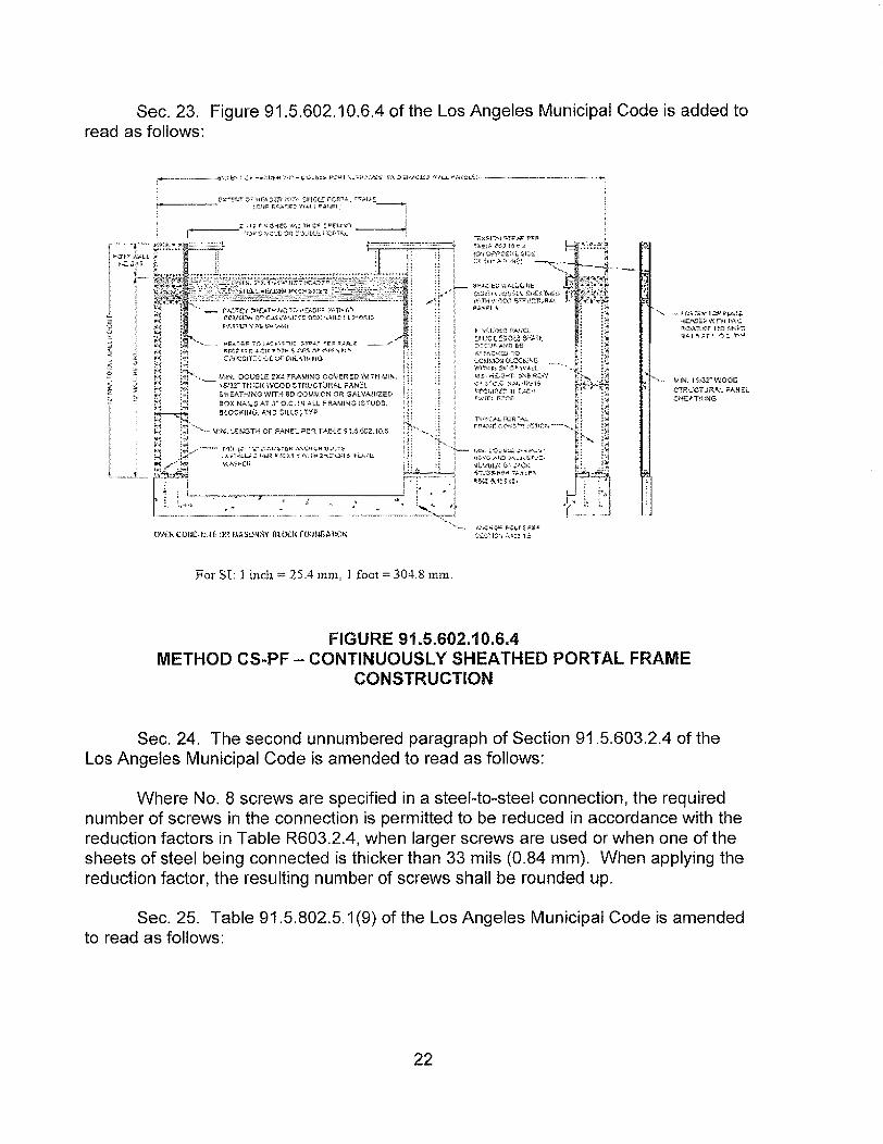
Sec. 23. Figure 91.5.602.10.6.4 of the Los Angeles Municipal Code is added toread as follows:
·3'~~
... ,<. ~~~> ,~?
.it.
~ ~;~
<,....~"". "~~~""-~";"~,;,"r~ P:J;;.&:I
s~t:n:)',,'~"':::!,1':·
For SI: l inch > 25.4 mrn, 1 foot = 304.8 mill.
"""~"" ~-f.$,:'£.,,: 1C;P1i"("';"'ftil:!(C .:::tR i,'I! 1TH1\\'0:":"~ ·;t,-et I/'t."'::~:t,";':t:1r,,:,,:I..~ ",r~' ~~, 'r,';'!
MIN. IS/3:;:~ "'JOOD.cTRUCTUf!:AL ;'lAS:':L-GHEAiriING
FIGURE 91.5.602.10.6.4METHOD CS~PF - CONTINUOUSLY SHEATHED PORTAL FRAME
CONSTRUCTION
Sec. 24. The second unnumbered paragraph of Section 91.5.603.2.4 of theLos Angeles Municipal Code is amended to read as follows:
Where No.8 screws are specified in a steel-to-steel connection, the requirednumber of screws in the connection is permitted to be reduced in accordance with thereduction factors in Table R603.2.4, when larger screws are used or when one of thesheets of steel being connected is thicker than 33 mils (0.84 mm). When applying thereduction factor, the resulting number of screws shall be rounded up.
Sec. 25. Table 91.5.802.5.1 (9) of the Los Angeles Municipal Code is amendedto read as follows:
22

TABLE 91.5.802.5.1 (9)
RAFTER/CEILING JOIST HEEL JOINT CONNECTIONSa, b, c, d, e, f, h
GROUND SNOW LOAD (pst)209 30 50 70
RAFTER RAFTERRoof span (feet)SPACINGSLOPE (inches) 12 20 28 36 12 20 28 36 12 20 28 36 12 20 28 36
Required number of 16d common nalls" b per heel jointsplices?' d, e, f
12 4 6 8 10 4 6 8 11 5 8 12 15 6 11 15 203:12 16 5 8 10 13 5 8 11 14 6 11 15 20 8 14 20 26
24 7 11 15 19 7 11 16 21 9 16 23 30 12 21 30 3912 3 5 6 8 3 5 6 8 4 6 9 11 5 8 12 15
4:12 16 4 6 8 10 4 6 8 11 5 8 12 15 6 11 15 2024 5 8 12 15 5 9 12 16 7 12 17 22 9 16 23 2912 3 4 5 6 3 4 5 7 3 5 7 9 4 7 9 12
5:12 16 3 5 6 8 3 5 7 9 4 7 9 12 5 9 12 1624 4 7 9 12 4 7 10 13 6 10 14 18 7 13 18 2312 3 4 4 5 3 3 4 5 3 4 5 7 3 5 7 9
7:12 16 3 4 5 6 3 4 5 6 3 5 7 9 4 6 9 1124 3 5 7 9 3 5 7 9 4 7 10 13 5 9 13 1712 3 3 4 4 3 3 3 4 3 3 4 5 3 4 5 7
9:12 16 3 4 4 5 3 3 4 5 3 4 5 7 3 5 7 924 3 4 6 7 3 4 6 7 3 6 8 10 4 7 10 1312 3 3 3 3 3 3 3 3 3 3 3 4 3 3 4 5
12:12 16 3 3 4 4 3 3 3 4 3 3 4 5 3 4 5 724 3 4 4 5 3 3 4 6 3 4 6 8 3 6 8 10
For 81: 1 inch = 25.4 mm, 1 foot = 304.8 mm, 1 pound per square foot = 0.0479 kPa.a. 40d box nails shall be permitted to be substituted for 16d common nails.b. Nailing requirements shall be permitted to be reduced 25 percent if naits are clinched.c. Heel joint connections are not required when the ridge is supported by a load-bearing wall, header orridge beam.d. When intermediate support of the rafter is provided by vertical struts or purlins to a load-bearing wall,the tabulated heel joint connection requirements shall be permitted to be reduced proportionally to thereduction in span.e. Equivalent nailing patterns are required for ceiling joist to ceiling jolst lap splices.f. When rafter ties are substituted for ceiling joists, the heel joint connection requirement shall be takenas the tabulated heel joint connection requirement for two-thirds of the actual rafter slope.g. Applies to roof live load of 20 psf or less.
23

h. Tabulated heel joint connection requirements assume that ceiling joists or rafter ties are located at thebottom of the attic space. When ceiling joists or rafter ties are located higher in the attic, heel jointconnection requirements shall be increased by the following factors:
Heel Joint ConnectionAdjustment Factor
1/31/41/51/6
1/10 or less
1.51.331.251.21.11
where:He;:: Height of celling joists or rafter ties measured vertically above the top of the rafter support walls.HR;:: Height of roof ridge measured vertically above the top of the rafter support walls.
i. Edge Distances, end distances' and spacing for nails shall be sufficient to prevent splitting ofthe wood.
Sec. 26. Urgency Clause. The City Council finds and declares that thisOrdinance is required for the immediate protection of the public peace, health andsafety for the following reason: In order for the City of Los Angeles to facilitate aseamless transition with the State of California and its Residential Code and maintainpredictability and streamlined case processing for the benefit of economic developmentduring distressed times, it is necessary to immediately adopt the foregoing exceptions,modifications and additions to the California Residential Code. Additionally, theCalifornia Residential Code becomes effective on January 1,2014 and the amendmentsto that code as reflected herein must be adopted by the City Council and becomeeffective as soon as possible. The Council, therefore, with the Mayor's concurrence,adopts this ordinance to become effective upon publication pursuant to Los AngelesCity Charter Section 253.
24

Sec. 27. The City Clerk shall certify to the passage of this ordinance and have itpublished in accordance with Council policy, either in a daily newspaper circulatedin the City of Los Angeles or by posting for ten days in three public places in the City ofLos Angeles: one copy on the bulletin board located at the Main Street entrance to theLos Angeles City Hall; one copy on the bulletin board located at the Main Streetentrance to the Los Angeles City Hall East; and one copy on the bulletin board locatedat the Temple Street entrance to the Los Angeles County Hall of Records.
I hereby certify that this ordinance was passed by the Council of the City ofLos Angeles, by a vote of not less than three-fourths of all of its members, at itsmeeting of .DEC, I 1 201$ .
HOll ~ L. W,OlCOTT. Irpm City Clerk
BY __:£~1~~Deputy
Approved DE_C---,2,,-3---,---,20..:..;;.13 __ ~L~ ayorACTING
Approved as to Form and Legality
Date I 2. {'() {13File No. ~ 1 ) , I 1- I Y
M:\Real Prop_Env_Land Use\Land Use\Kim Westhoff\DBS--2013 Code Amendment\2014 Residential Master Ordinance KRWDraft.docx
25