origami-based earthworm-like locomotion robots
TRANSCRIPT

Bioinspiration & Biomimetics
PAPER
Origami-based earthworm-like locomotion robotsTo cite this article: Hongbin Fang et al 2017 Bioinspir. Biomim. 12 065003
View the article online for updates and enhancements.
This content was downloaded from IP address 175.159.0.243 on 17/10/2017 at 04:14

© 2017 IOP Publishing Ltd
1. Introduction
Earthworms, a kind of soft animal commonly found living in moist soils, can move effectively in various environments, especially, in confined underground burrows. Earthworms’ legless locomotion ability can be ideal for navigating into limited spaces, and as a result is attractive for scientists and engineers to develop earthworm-inspired locomotion robots. Potential applications of earthworm-like robots are wide-spread, including moving through slender pipelines to inspect and clean foreign objects, burrowing through rubbles to search and rescue, and entering in gastrointestinal tracts to examine and treat diseases (e.g. [1–9]). Earthworms’ outstanding moving capability originates from their particular morphology structures [10–12], which mainly includes three aspects. (i) Metameric segmentation:
with metamerism, the earthworm’ body is divided into a large number of segments by septa (figure 1(a)); each segment contains a repetition of muscle tissues to work independently, i.e. deformation of one segment will not affect the state of the adjacent segments. (ii) Antagonistically working muscles: each segment has two layers of muscles (circular and longitudinal muscles) that work antagonistically to each other (figure 1(a)). Contraction of the circular muscles will axially elongate but radially contract the segment, and contraction of the longitudinal muscles will axially shorten but radially expand the segment (figure 1(b)). (iii) Setae: almost all segments possess bristle-like setae to anchor parts of the body during movement (figure 1(a)), which makes the directed locomotion of earthworms possible. With these morphology advantages, the earthworm moves by coordinated contractions of longitudinal and circular muscles. The
H Fang et al
065003
BBIICI
© 2017 IOP Publishing Ltd
12
Bioinspir. Biomim.
BB
1748-3190
10.1088/1748-3190/aa8448
6
1
17
Bioinspiration & Biomimetics
IOP
10
October
2017
Origami-based earthworm-like locomotion robots
Hongbin Fang1 , Yetong Zhang and K W WangDepartment of Mechanical Engineering, University of Michigan, Ann Arbor, MI 48105, United States of America1 Author to whom any correspondence should be addressed.
E-mail: [email protected] (H Fang), [email protected] (Y Zhang) and [email protected] (K-W Wang)
Keywords: bio-inspired robot, origami ball, multi-stability, compliant robot, locomotion gait
AbstractInspired by the morphology characteristics of the earthworms and the excellent deformability of origami structures, this research creates a novel earthworm-like locomotion robot through exploiting the origami techniques. In this innovation, appropriate actuation mechanisms are incorporated with origami ball structures into the earthworm-like robot ‘body’, and the earthworm’s locomotion mechanism is mimicked to develop a gait generator as the robot ‘centralized controller’. The origami ball, which is a periodic repetition of waterbomb units, could output significant bidirectional (axial and radial) deformations in an antagonistic way similar to the earthworm’s body segment. Such bidirectional deformability can be strategically programmed by designing the number of constituent units. Experiments also indicate that the origami ball possesses two outstanding mechanical properties that are beneficial to robot development: one is the structural multistability in the axil direction that could contribute to the robot control implementation; and the other is the structural compliance in the radial direction that would increase the robot robustness and applicability. To validate the origami-based innovation, this research designs and constructs three robot segments based on different axial actuators: DC-motor, shape-memory-alloy springs, and pneumatic balloon. Performance evaluations reveal their merits and limitations, and to prove the concept, the DC-motor actuation is selected for building a six-segment robot prototype. Learning from earthworms’ fundamental locomotion mechanism—retrograde peristalsis wave, seven gaits are automatically generated; controlled by which, the robot could achieve effective locomotion with qualitatively different modes and a wide range of average speeds. The outcomes of this research could lead to the development of origami locomotion robots with low fabrication costs, high customizability, light weight, good scalability, and excellent re-configurability.
PAPER2017
RECEIVED 15 June 2017
REVISED
25 July 2017
ACCEPTED FOR PUBLICATION
4 August 2017
PUBLISHED 10 October 2017
https://doi.org/10.1088/1748-3190/aa8448Bioinspir. Biomim. 12 (2017) 065003

2
H Fang et al
earthworm first contracts the longitudinal muscles of its posterior segments and protrudes the setae to form the anchor, then contracts the circular muscles of the front end of the body, causing the anterior segments to extend forward. The contractions of longitudinal muscles pass backward from segments to segments, drawing the rear end of the body forward, followed by contractions of anterior segments’ circular muscles in turn, forming a peristalsis wave travelling from the head to the tail [10, 11] (i.e. retrograde peristalsis wave, see schematic illustration in figure 1(c)).
Earthworm’s morphology characteristics and locomotion mechanism provide important guide-lines to the design and control of earthworm-like robots. The metameric segmentation suggests a peri-odic structure of the robot (e.g. [2–5, 8, 13–16]); the antagonistically working muscles indicate that the robot segments should be able to produce both radial and axial deformations during actuation (e.g. [2–5, 13–15, 17]); the setae effect implies the necessity of incorporating anisotropic resistance or anchoring mechanisms in the robot design [17–20]; and the retrograde peristalsis wave offers a basic principle for locomotion gait construction [21–23] and locomo-tion control [17, 24–26]. Particularly, the ability to generate antagonistic bi-directional deformations plays a key role in robot segment design and actuation. Note that although in some designs the robot segments can only generate axial deformations, locomotion is still possible because the anchoring effect is achieved without radial deformations but through additional
bristles or specialized anchoring segments (e.g. micro-needles or clamping devices [18, 19, 27–31]). Employ-ing two independent actuators in a segment is also a feasible way to produce radial and axial deformations (e.g. using two antagonistically shape-memory-alloy (SMA) actuators [32, 33]). Recently, incorporating inherent coupling mechanisms to generate bi-direc-tional deformations through a single actuation is more preferred in earthworm-like robot development. The coupling can originate from inherent material proper-ties (e.g. McKibben artificial muscles [2, 3]) or struc-tural mechanisms (e.g. buckled beams [13, 15], linkage structures [14, 26], and coupled cables [17, 26]). With coupled deformations, it would not be necessary to employ multiple types of actuators or set additional bristles on the segments, which could greatly simplify the robot design, reduce the number of actuators, and increase the system robustness. As a result, exploring such structures in earthworm-like robots is always an important research topic.
Along with the technical progress and increases in requirements, the development of modern earth-worm-like robots is facing more challenges including further miniaturization of size and weight, reduction of fabrication costs, improvement of customizability, and enrichment of functionalities. Parts of these chal-lenges lie in the traditional robot development pro-cess, namely, ‘part design—part fabrication—final assembly’. Such process has increasingly shown its limitations because it calls for highly specialized fabri-cation and cumbersome, costly, and imprecise assem-bly (especially in mesoscale), it lacks customizability and agility on revising or updating the robot designs, and it is deficient in further reducing the robot size and weight.
Recently, origami, the art of paper folding, intro-duces novel inspiration into various areas of science, architecture, and engineering. With origami tech-niques, people can pattern a single 2-dimensional (2D) flat sheet of material and then fold it into pre-specified 3-dimensional (3D) shapes. As a novel 3D forming technique, origami exhibits the following features:
(1) Large design space of 2D patterns. 2D patterns can be created using existing computational and design tools with exceptional large design space [34–36]. By designing 2D patterns, origami is capable of producing complex 3D geometries.
(2) Rapid and precise 2D fabrication. Instead of 3D shaping, the planar materials are compatible with a wide range of commercial 2D fabrication techniques that are inexpensive, fast, and precise, such as lithography [37], laser machining [38], and basic chemical etching [39], etc. A flat pattern is also convenient for transportation.
(3) Replacing assembly with folding. Without cumbersome assembling process, complex
Figure 1. Schematic illustration of the morphology characteristics and locomotion mechanism of the earthworm. (a) Longitudinal and cross sections of an earthworm. (b) Antagonistically working circular muscles (dashed) and longitudinal muscles (solid), the contracted muscles are denoted by bold. (c) Retrograde peristalsis wave of muscular contractions.
Bioinspir. Biomim. 12 (2017) 065003

3
H Fang et al
3D structures can be precisely constructed just by folding 2D patterns. The folding process can be performed manually or autonomously if automated folders [40], embedded folding actuators, or active materials [41, 42] are adopted.
(4) Scale independence. Theoretically, origami folding is independent of size, i.e. the folded structure can be scaled to different dimensions (e.g. from nano-origami [43] to origami space structures [44]) without altering their kinematical properties. However, if the origami structure is scaled down to a very small size, the 2D fabrication techniques and folding processes would become challenging; and on the other hand if it is extensively scaled up, the inertial effect and the structure’s relative stiffness need to be considered.
(5) Material independence. Theoretically, for rigid-foldable or nearly rigid-foldable origami, the folding kinematics and folding-induced kinematical properties (e.g. deformation mechanisms [45], Poisson’s ratio [45, 46], and self-locking [47], etc) are independent of the materials been folded.
(6) Light weight but with rigidity. Origami structures can be made of thin and light 2D materials (e.g. paper and polymer films) that were seldom considered in previous robot prototyping. Using these materials could significantly reduce the weight of the robot. Meanwhile, although the 2D sheets always show low rigidity, the folded origami structure would have higher rigidity owing to the folded architectures [48, 49].
(7) Extraordinary mechanical properties. Folding also offers the origami structures with certain extraordinary properties that are unseen in raw materials and engineering structures, such as multistability [50, 51] and piecewise stiffness [47], etc.
(8) Re-configurability. Origami structures are able to change their configurations substantially without altering the designs but just by folding. At different configurations, the structure’s mechanical properties can be diverse [52, 53].
The abovementioned features of origami bring exciting opportunities to the field of robotics. Origami could be utilized to overcome the drawbacks in the tra-ditional ‘part design—part fabrication—final assem-bly’ process and to potentially make a breakthrough in robot design and fabrication. For example, the large design space of 2D origami pattern (feature (1) above) could offer high customizability and agility to robot development, including revising robot designs, add-ing/reducing structural modules, and introducing
new functional components. With 2D patterning and folding that are efficient and precise (features (2) and (3)), the overall fabrication costs (money costs, human efforts, and time) can be reduced; this is especially sig-nificant if one realizes that the electronics, circuitry, and power supply can also be embedded or printed on the 2D pattern as a monolithic [38, 54, 55]. The scale and material independence of origami structures (features (4–6)) could promote the development of origami robot at different scales, e.g. miniature origami robot [56]. In addition, origami folding could also endow the robots with surprising re-configurability [57] and multi- functionality [55, 58] (features (7) and (8)).
Based upon the facing challenges in robot develop-ment and the promising origami solution, it is inter-esting to correlate the earthworm-inspired guidelines with the origami folding to develop origami earth-worm-like robots. Note that several worm-like robot designs were proposed to use origami structures for effective shape changes [59, 60]; however, the adopted waterbomb-based origami [59] and the Kresling ori-gami [60] could only produce axial deformations, and hence they did not take advantage of the earthworms’ morphology characteristics nor explore origami’s antagonistically-coupled bi-directional deformability. In addition, none of these efforts has developed rigor-ous understanding on how to integrate the origami kinematical and mechanical properties into the robot designs in a synergistic way to holistically manifest the attractiveness of origami.
To advance the state of the art, a novel earthworm-like origami robot is developed in this research by merging the bioinspired guidelines with the origami folding approach. The new concept here is to strategi-cally integrate the origami ball structures with multiple types of actuators to construct earthworm-like robot ‘body’, and to learn from the earthworm’s retrograde peristalsis waves to create earthworm-inspired ‘control-ler’. Specifically, this research thoroughly investigates the design, kinematical and mechanical characteristics, actuation, and control of an origami-ball-based earth-worm-like locomotion robot. We find that the origami ball structure shows morphology similarities with the earthworm body segment, i.e. it is able to output sig-nificant axial and radial deformations in an antagonistic way. Such antagonistically-coupled deformation mech-anism allows the origami ball to switch its configura-tion by just axial actuation. In addition, the origami ball possesses outstanding kinematical and mechanical characteristics that are beneficial to the earthworm-like robot development, including strong programmability on bi-directional deformability, structural multistabil-ity and compliance. Based on the origami ball struc-tures, three robot segments that incorporate DC-motor, SMA springs, and pneumatic balloon are designed and proto typed. Each prototype shows different merits and limitations, in terms of actuation speed, design simplic-ity, and applicability. To verify the overall robot design effectiveness, a 6-segment origami-ball-based earth-
Bioinspir. Biomim. 12 (2017) 065003

4
H Fang et al
worm-like locomotion robot is prototyped utilizing the DC-motor actuation. An earthworm-inspired gait con-troller is also designed to generate gaits, which control the robot to perform effective locomotion with different modes and diverse average speeds.
2. Design and fabrication of origami structures
Following the earthworms’ morphology characteristics, candidate origami structures for constructing earthworm-like robots should be able to produce bi-directional deformations (i.e. axial and radial directions) antagonistically; in other words, these structures are expected to have a positive Poisson’s ratio. In previous origami research, several structures that satisfy the deformation requirements have been proposed, such as stacked Miura-ori origami structure [45, 46], origami tubes with various cross sections [61–63], origami springs [64], and origami ball structure [57], etc. Their 2D crease patterns and corresponding two qualitatively different configurations are shown in figure 2.
In this paper, the origami ball structure (figure 2(d)) is selected for developing earthworm-like robots. This is because its 2D crease pattern is a periodic rep-etition of square waterbomb units that does not call for specifically-targeted design. Generally, the 2D crease pattern of an origami ball consists of m layers of n waterbomb units (i.e. m × n units). In addition, the folded origami ball is cylindrical that is suitable for limited and vulnerable working environment. We will show in the next section that the origami ball struc-tures also provide excellent kinematical and mechani-cal properties that are beneficial to earthworm-like robot development.
Various polyester materials can be used for making the origami ball, such as polyethylene tere-phthalate (PETE), polyether ether ketone (PEEK), polytetrafluoroethylene (PTFE), and polyimide [59, 65]. Generally, these materials are safe, non-toxic, strong, lightweight, and flexible at normal temper-atures. Among them, the PETE film is appropriate in a non-thermal scenario because PETE can be easily cut, patterned, and folded, and the folded structure has suitable stiffness. However, PETE has a relatively low softening temper ature around 82 °C such that it is not thermal resistant. On the other hand, the sof-tening temperatures of PEEK, PTFE, and polyimide can be higher than 150 °C, making them more usable in thermal-related applications. In this research, we select the PETE film and PEEK film for constructing origami ball structures; the former will be used in a room- temperature environ ment, and the latter will be used if it will be operated in a higher temperature.
In terms of fabrication, the key technique is to generate significant stiffness difference between the origami facets and the crease lines so that the creases can be flexible for folding while the facets can remain rigid during folding. The stiffness difference can be
achieved through either increasing the facet stiffness (additive process) [37, 54, 66] or reducing the crease stiffness (subtractive process) [38, 39, 57, 59]. Com-monly, additive process uses different mat erials for facets and creases, which complicates the 2D fabrica-tion and reduces the efficiency. The subtractive pro-cess, on the other hand, needs only one mat erial; the stiffness decrease at the creases is achieved through reducing the material thickness or removing part of the mat erial. In this paper, we use laser-based machin-ing techniques to cut and pattern flat sheet because of its efficiency, precision, low cost, and universality.
Figure 3(a) shows the 2D crease pattern of a 3 × 8 origami ball, where the length of the square waterbomb unit is 37.9 mm. The creases are perforated to some extent such that the bending stiffness of the creases are weakened (the dashed lines are the perforated parts). With perforation, the reduced stiffness is symmet-ric for both mountain and valley folding. We also cut small holes at the vertices where multiple creases inter-sect to prevent stress concentration. In addition, to facilitate connection, additional parts are added on the crease pattern (shown in grey in figure 3(a)); and end patterns are designed (figure 3(b)), which will be con-nected with the origami ball at the ends. Laser machin-ing could produce a 2D origami ball pattern and two end patterns with high precision in about 8 min (figure 3(c)), and we spend about 20 min to manually fold and
Figure 2. Origami structures showing antagonistic radial and axial deformations that can be employed as the earthworm-like robot segment. (a) Stacked Miura-ori structure [45, 46]; (b) origami tubes with various cross-sections, which can be designed through summation and subtraction processes [61–63]; (c) origami spring structure [64]; (d) origami ball structure [57]. In (a), (c), and (d), the 2D flat pattern and two qualitatively different configurations are given; in the 2D patterns, the solid and dashed lines denote the mountain and valley folds, respectively. Some edges need to be glued together to obtain the 3D shapes.
Bioinspir. Biomim. 12 (2017) 065003

5
H Fang et al
paste them into an origami ball (figure 3(d)). For sub-sequent connection and installation purposes, acrylic plates with the same dimensions as the internal poly-gon of the end pattern (figure 3(b)) will be laser cut, and they will be connected with the origami ball at the ends. In what follows, unless stated otherwise, this ×3 8 origami ball design will be used for mechanical
tests and robot fabrication.
3. Kinematics and mechanics of origami ball structures
To utilize the origami ball as a robot segment, a comprehensive understanding of the structure’s kinematics and mechanics is necessary. In this section, theoretical and experimental efforts are devoted to this topic, with particular focus on the benefits that the origami ball brings for robot development.
3.1. KinematicsWe first analyze the degree of freedom (DOF) of an origami ball structure for rigid folding. Theoretically, rigid folding of a waterbomb unit can be modeled as a spherical 6R linkage [67, 68], with each internal crease acting as a revolute joint and the facets between creases as rigid links. Hence a waterbomb unit possesses three DOF, which could be reduced to one if assuming symmetric folding [67, 68]. Chen et al [67] have revealed that there exist two symmetric rigid-folding paths for waterbomb pattern, one corresponds to a uniform expansion/
contraction, and the other involves a bending between layers. Here if the origami ball structure is folded with rotational symmetry and reflectional symmetry, the folding remains single DOF. Due to the geometry constraints at the ends (applied by the end patterns and the end acrylic plates), the origami ball folding cannot follow the uniform expansion/contraction path, but takes a deformation path involving bending between waterbomb layers (see explanation below).
We take a 3 × 8 origami ball structure (without end patterns) as an example to study its kinematics. For simplicity, the length of the square waterbomb unit is set as l2 . A fundamental composition of the origami ball is derived, and two groups of vertices, namely, ‘1–2–3–4–5–6’ and ‘a–b–c–d–e’ (figures 4(a) and (b)), are selected for examination. We use six param eters, say, x1, x2, and θ θ~1 4, to characterize the position of each vertex =r z i a e, 1, ..., 6; , ...,i i( ) ( ), where ri and zi denote the distances to the rotational and reflectional axes, respectively
θ θ θ θθ θ
θ θ θ θθ θ
θ θ
= + + = + += + = += == + + = += + == = + +
r x l l z l l lr x l z l lr x z lr x l l z l lr x l z lr x z l l l
cos cos , sin sin ;cos , sin ;
, ;cos 2 cos , sin 2 sin ;cos , sin ;
, sin sin .
a a
b b
c c
1 1 2 1 1 2 1
2 1 2 2 2
3 1 3
2 4 3 4 3
2 4 4
2 2 1
( ) ( ) ( ) ( )( ) ( )
( ) ( ) ( ) ( )( ) ( )
( ) ( ) (1)
The positions of vertices ‘4’, ‘5’, ‘6’, and ‘d’, ‘e’, ‘f’ can be obtained by considering the reflection symmetry about the reflectional axis. The above mentioned ‘uniform expansion/contraction’ indicate that the angle θ3 will remain 90°, while ‘bending between layers’ indicate θ3 will change with respect to the folding process. Note that the positions of these points are not independent, instead, their relative distances are constrained by the geometric lengths of the creases ‘1-a’, ‘2-a’, ‘2-b’, ‘3-b’, and ‘3-c’, which give rise to the following constraint equations
ρρρρρ
= + − + − == + − + − = += + − + − = += + − + − == + − + − = +
−
−
−
−
−
l r r r r z z l
l r r r r z z l l
l r r r r z z l l
l r r r r z z l
l r r r r z z l l
2 cos ,
2 cos ,
2 cos ,
2 cos ,
2 cos .
a a a a
a a a a
b b b b
b b b b
c c c c
12
12 2
1 12 2
22
22 2
2 22 2 2
22
22 2
2 22 2 2
32
32 2
3 32 2
32
32 2
3 32 2 2
( ) ( )( ) ( )( ) ( )( ) ( )( ) ( )
(2)In equation (2), • denotes the Euclidean distance; ρ denotes the central angle at the rotational axis corresponding to half waterbomb unit in the ball; in this 3 × 8 origami ball,
�ρ = 360 16/ . If assigning θ3 as
the independent variable and by numerically solving the above five constraint equations, each vertex’s position can be determined.
Then we can evaluate the axial and radial dimen-sions of the origami ball. In the axial direction, we focus on the distances between vertices ‘a-e’, ‘1-6’, and ‘3-4’, i.e. =−l z2a e a, =−l z21 6 1, and =−l z23 4 3; and in the radial direction, we focus on r2 3 and r2 b. Their normalized values with respect to l are plotted in figure 4(c). In addition, we can further examine the
Figure 3. Design and prototype of an origami ball structure. (a) 2D crease pattern of a ×3 8 origami ball; for connection purpose, additional parts (grey) are added on the origami ball pattern. (b) Designs of the end patterns and end acrylic plates; the acrylic plates can be further customized for installation and connection purposes. In (a) and (b), the lines will be perforated by laser. (c) The laser-machined 2D crease pattern and end patterns made of PETE films. (d) The folded origami ball (with end patterns), shown in axially-extended and axially-contracted configurations.
Bioinspir. Biomim. 12 (2017) 065003

6
H Fang et al
Figure 4. Kinematics of a 3 × 8 origami ball structure. Two groups of vertices ‘1–2–3–4–5–6’ and ‘a–b–c–d–e’ are picked for kinematic analysis, shown on the 2D crease pattern (a) and on the folded origami ball (b). Their positions with respect to the rotational and reflectional axes can be described by six parameters. (c) Normalized axial and radial dimensions of the origami ball with respect to the folding angle θ3. The origami ball’s axial length ( /L l) and radial diameter ( /W l) are denoted by bold curves. The origami ball’s configurations i, ii, and iii are depicted. (d) Normalized total difference ( /R l) with respect to θ3. Based on whether =R 0, the rigid-foldable and non-rigid-foldable ranges are distinguished in (c) and (d).
axial length L and radial diameter Wof the origami ball. Here the axial length L is defined as the maximum axial dimension, and the radial diameter W is defined as the maximum radial dimension, i.e.
{ } { }
{ }– – –= =
=
L l l l z z z
W r r
max , , max 2 , 2 , 2 ,
max 2 , 2 .
a e a
b
1 6 3 4 1 3
3 (3)
The normalized length and diameter are denoted in figure 4(c) with bold.
If we examine the distance between the origami ball ends, i.e. la e– , we find that it firstly has a small increase from configurations i (
�θ = 903 ) to ii and then
decreases to zero at configuration iii (�
θ = 2083 ). To prevent facet collision, further folding is not allowed after configuration iii. However, figure 4(c) reveals that during the folding process, the origami ball’s axial length measure does not always stick to la e– , but changes from la e– to l1 6– , and finally converges at l3 4– . Hence, instead of reducing to zero, the axial length reaches a constant at configuration iii. On the other hand, the origami ball’s radial diameter W takes the minimum at configuration i and then increases with respect to the folding; after configuration ii, the increase slows down and the radial diameter stays high around configuration iii.
The obtained origami ball kinematics provides the basic information of how many axial and radial defor-mations the origami ball can achieve. Figures 4(c) indicates that overall the origami ball’s axial and radial deformations are antagonistic to each other. If we transform the origami ball from configuration i to iii, a 52% contraction of the axial length (L l/ decreases from 4.2 to 2) or a 100% contraction of the distance between the two ends ( l la e /– decreases from 4.2 to 0) can be
achieved. Meanwhile, a 155% expansion of the radial diameter (W l/ increases from 2.09 to 5.33) is achieved simultaneously. Such antagonistic deformation mech-anism and tremendous axial deformability makes the origami ball ideal for constructing earthworm-like robot segments.
It is worth noting that exact solutions of equa-tion (2) do not necessarily exist because rigid-folding cannot be guaranteed during the whole folding pro-cess. If the folding is rigid, i.e. the creases and the facets remain un-deformed during folding, then the relative distances l a1- , l a2- , l b2- , l b3- , and l c3- should be identical with the corresponding geometric lengths, in other words, equation (2) should be completely satisfied. On the other hand, if the folding is no longer rigid, i.e. the creases or facets have to deform during folding, then the relative distances will be different with the geometric lengths, and equation (2) cannot be fully satisfied. Hence, instead of exact solutions, only approximated solutions of equation (2) can be found. To check the origami ball’s rigid-foldability, we exam-ine the total differences R between the calculated rela-tive distances and the geometric lengths, i.e.
= − + − + −
+ − + −
R l l l l l l
l l l l
2 2
2 ,
a a b
b c
1- 2- 2-
3- 3-
(4)
and we plot the corresponding normalized value (R l/ ) with respect to the folding angle θ3 in figure 4(d). It reveals that at the starting stage, the total difference is zero, indicating rigid-folding of the structure. While when
�θ > 115.83 , the total difference is no longer zero
because the exact solutions of equation (2) cannot be found, suggesting non-rigid-folding of the origami ball. Hence,
�θ =115.83 is a boundary between the
rigid-foldable and non-rigid-foldable ranges (figures
Bioinspir. Biomim. 12 (2017) 065003
7
H Fang et al
4(c) and (d)) for this 3 × 8 origami ball. Interestingly, �
θ =115.83 exactly corresponds to configuration ii where the ball has the maximum length.
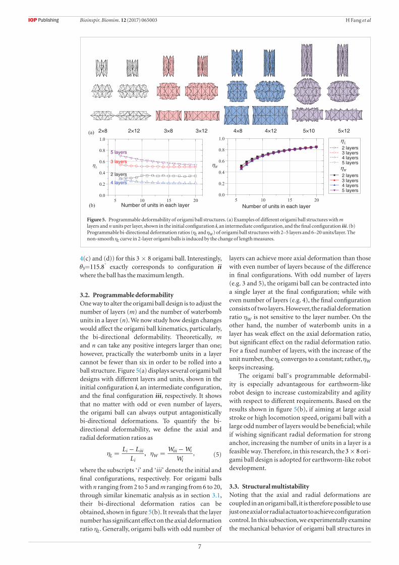
3.2. Programmable deformabilityOne way to alter the origami ball design is to adjust the number of layers (m) and the number of waterbomb units in a layer (n). We now study how design changes would affect the origami ball kinematics, particularly, the bi-directional deformability. Theoretically, m and n can take any positive integers larger than one; however, practically the waterbomb units in a layer cannot be fewer than six in order to be rolled into a ball structure. Figure 5(a) displays several origami ball designs with different layers and units, shown in the initial configuration i, an intermediate configuration, and the final configuration iii, respectively. It shows that no matter with odd or even number of layers, the origami ball can always output antagonistically bi-directional deformations. To quantify the bi-directional deformability, we define the axial and radial deformation ratios as
η η=−
=−L L
L
W W
W, ,L
i iii
iW
iii i
i (5)
where the subscripts ‘i’ and ‘iii’ denote the initial and final configurations, respectively. For origami balls with n ranging from 2 to 5 and m ranging from 6 to 20, through similar kinematic analysis as in section 3.1, their bi-directional deformation ratios can be obtained, shown in figure 5(b). It reveals that the layer number has significant effect on the axial deformation ratio ηL. Generally, origami balls with odd number of
layers can achieve more axial deformation than those with even number of layers because of the difference in final configurations. With odd number of layers (e.g. 3 and 5), the origami ball can be contracted into a single layer at the final configuration; while with even number of layers (e.g. 4), the final configuration consists of two layers. However, the radial deformation ratio ηW is not sensitive to the layer number. On the other hand, the number of waterbomb units in a layer has weak effect on the axial deformation ratio, but significant effect on the radial deformation ratio. For a fixed number of layers, with the increase of the unit number, the ηL converges to a constant; rather, ηW keeps increasing.
The origami ball’s programmable deformabil-ity is especially advantageous for earthworm-like robot design to increase customizability and agility with respect to different requirements. Based on the results shown in figure 5(b), if aiming at large axial stroke or high locomotion speed, origami ball with a large odd number of layers would be beneficial; while if wishing significant radial deformation for strong anchor, increasing the number of units in a layer is a feasible way. Therefore, in this research, the ×3 8 ori-gami ball design is adopted for earthworm-like robot development.
3.3. Structural multistabilityNoting that the axial and radial deformations are coupled in an origami ball, it is therefore possible to use just one axial or radial actuator to achieve configuration control. In this subsection, we experimentally examine the mechanical behavior of origami ball structures in
Figure 5. Programmable deformability of origami ball structures. (a) Examples of different origami ball structures with m layers and n units per layer, shown in the initial configuration i, an intermediate configuration, and the final configuration iii. (b) Programmable bi-directional deformation ratios (ηL and ηW) of origami ball structures with 2–5 layers and 6–20 units/layer. The non-smooth ηL curve in 2-layer origami balls is induced by the change of length measures.
Bioinspir. Biomim. 12 (2017) 065003

8
H Fang et al
the axial direction. Through the method introduced in section 2 and based on the design shown in figure 3, four ×3 8 origami ball prototypes are fabricated with PETE films of different thickness: 0.025 mm, 0.05 mm, 0.075 mm, and 0.125 mm. For each origami ball prototype, five axial compression/extension tests are performed, and the obtained force-displacement relations are averaged and plotted in figure 6. It shows that axial actuation could effectively fold the origami balls and achieve bi-directional deformations. During the axial compression/extension process, the origami ball experiences three different stable configurations ‘A’, ‘B’, and ‘C’ (figure 6(e)), where ‘A’ correspond to an axially-extended configuration; ‘B’ corresponds to two possible configurations, one with the top layer snapped in (Bt), and the other with the bottom layer snapped in (Bb); and ‘C’ corresponds to the axially-contracted configuration. It is worth noting that neither the compression nor extension process can fold the origami ball to configuration i shown in figure 4(c) because it calls for increase (decrease) of length during an axial contraction (extension) process.
Particularly, with PETE film of thickness 0.05, 0.075, and 0.125 mm, the origami balls exhibit obvi-ous multistability in the axial direction. In detail, the three configurations ‘A’, ‘B’, and ‘C’ are stable, and there are obvious snap-through phenomena when switching among them. In figures 6(b)–(d), the stable configurations are the intersection points of the force-displacement curve and the =F 0 line with positive slope (solid circles), and the snap-through transitions are those curve segments with negative slope. Such stable configurations and snap-through transitions are observed in both the compression and extension processes. Moreover, by changing the PETE film thick-ness, the origami ball’s mechanical characteristics in the axial direction can be effectively tailored. With very thin film, the origami ball loses the multistable and snap-through characteristics (e.g. 0.025 mm film in figure 6(a)). With the increasing of film thickness (e.g. 0.05 mm, 0.075 mm, and 0.125 mm in figures 6(b)–(d)), the origami balls gain multistability; the tangent stiffness at the stable configurations (manifesting as the slopes of the force-displacement curve) and the critical forces for snap-through transitions also increase significantly.
Note that unlike the previous rigid-foldable ori-gami structures [50, 51, 69] that the bistability or multistability comes from the crease rotational stiff-ness and nonlinear geometry, the multistability in origami ball mainly originates from the elastic defor-mation of facets and creases because the ball partly loses rigid-foldability [49]. The origami ball’s stable configurations correspond to the local minima of elastic potential stored in the facets and creases. Since the elastic potential minima can be known a priori as a function of the origami geometry, multistability offers tremendous benefits in terms of robot control imple-mentation. For instance, due to the restoring force, the
robot segment could hold its state at the stable axially-contracted configuration and reject disturbance with-out a holding control; the robot segment can also fast switch between stable configurations without a lasting actuation control, but relying on the intrinsic elastic snap-through transitions. However, it is also worth noting that if with multistability the axial actuation has to be bi-directional so as to overcome the restoring force and achieve transitions between stable configu-rations. In such case, additional mechanisms may be needed for actuators like SMA and motor-driven cords because they can only output pulling forces.
3.4. Structural complianceWe then examine the mechanical characteristics of the origami ball in the radial direction. Similarly, five compression tests are performed on each origami ball prototype in the radial direction, at both the axially-extended configuration ‘A’ and the axially-contracted configuration ‘C’. Unlike the axial scenario, radial actuation is unable to switch the origami ball among configurations ‘A’, ‘B’, and ‘C’, indicating the inapplicability of radial actuators in robot manipulation. Figure 7 displays the averaged force-displacement curves of the four origami ball prototypes, from which the structural compliance (defined as the inverse of stiffness) can be read. Overall
Figure 6. Force-displacement responses of origami ball prototypes under axial compression (solid) and axial extension (dashed) tests. The prototypes are made of PETE films with thickness (a) 0.025 mm, (b) 0.05 mm, (c) 0.075 mm, and (d) 0.125 mm. Stable configurations are denoted by solid dots. In (d), the tangent stiffness and the critical force for snap-through are denoted. Photos of the origami ball prototype at the stable configurations ‘A’, ‘B’, and ‘C’ are given in (e).
Bioinspir. Biomim. 12 (2017) 065003

9
H Fang et al
at the axially-extended configuration ‘A’, the origami balls show high compliance, i.e. they are relatively easily to deviate from their stable configuration; while at the axially-contracted configuration ‘C’, the origami ball is less compliant and is more resistant to radial deviations within a safe range. If going beyond the safe range, the axially-contracted ball may lose stability owing to the inclination of end plates (figure 7(f)). In addition, figure 7 demonstrates that the radial compliance can be effectively tailored by adjusting the film thickness (e.g. at the axially-extended configuration, the compliance increases more than 57 times from 3.3 mm N−1 to 188.3 mm N−1 by changing the film thickness from 0.125 mm to 0.025 mm).
Origami ball’s mechanical characteristics in the radial direction will also benefit the earthworm-like robot development. Since radial displacement is unable to switch the origami ball configuration, the robot control robustness can be insured by prevent-ing unexpected configuration switch owing to radial disturbance. Meanwhile, the relatively lower compli-ance at the axially-contracted configuration could help the robot segment to maintain firm anchor with the environ ment for effective locomotion. On the other hand, with some compliance in the radial direction, especially, as the axially-extended configuration, the
robot would have good tolerance with respect to radial environment change and apply less damage to vulner-able working media.
4. Designs and prototypes of origami-ball-based robot segment
With the knowledge of origami ball’s kinematics and mechanics, we then integrate origami ball structures with axial actuation mechanisms (because only axial actuation can achieve origami ball configuration switch) into earthworm-like robot segments. This section introduces the robot segment design, prototyping, and performance evaluation.
4.1. DesignsThree axial actuators are employed in this research for constructing earthworm-like robot segments, they are: a DC gear motor, SMA springs, and a pneumatic balloon. Figures 8(a)–(c) show the corresponding CAD designs of the robot segments, displaying at the axially-extended and axially-contracted configurations.
Note that the origami ball could stay at stable con-figurations without holding forces. To transform the segment between the axially-extended configuration and the axially-contracted configuration, the actua-tor should be able to output both pulling and pushing forces to overcome the corresponding restoring forces. However, the motor-driven cord cannot output any pushing force, and the SMA springs can output very weak pushing force. Hence, additional pushing mech-anism is needed to be incorporated into the design to switch the origami ball from the axially-contracted con-figuration to the axially-extended configuration. Here pre-bent spring-steel belts are coupled with the origami ball structure to provide passive pushing forces.
Figure 7. Force-displacement responses of origami ball prototypes under radial compression tests; both the axially-extended (solid) and axially-contracted configurations (dashed) are tested. The prototypes are made of PETE films with thickness (a) 0.025 mm, (b) 0.05 mm, (c) 0.075 mm, and (d) 0.125 mm. The structural compliances are obtained through linear fitting and are labeled on the figure (with coefficient of determination R2). Photos of the axially-extended ball and axially-contracted ball during compression are displayed in (e) and (f), respectively.
Figure 8. CAD designs of the origami-based earthworm-like robot segments: (a) the DC-motor design; (b) the SMA-spring design; and (c) the balloon design. The axially-extended configuration and the axially-contracted configuration are shown for each design.
Bioinspir. Biomim. 12 (2017) 065003

10
H Fang et al
In the DC-motor design (figure 8(a)), when the DC motor is actuated, the cord pulls the origami ball and the spring-steel belts into the axially-contracted configuration; and when the DC motor is reversely actuated, the pre-bent spring-steel belts push the robot segment back to the axially-extended configuration. The SMA design (figure 8(b)) adopts a similar mech-anism to actuate the robot segment, where the pulling is generated by heating the SMA springs, and the push-ing is mainly achieved by the pre-bent spring-steel belts when the SMA springs are cooling down. The bal-loon design (figure 8(c)) adopts a different actuation mechanism. When applying inflation pressure (con-trolled by high accuracy I/P transducer), the balloon is expanded in the axial direction, pushing the robot segment into the axially-extended configuration; when releasing the pressure, the elastic balloon itself is expected to provide enough force to pull the robot segment back to the axially-contracted configuration.
4.2. Prototypes and performance evaluationsThe origami balls are fabricated following the design shown in figure 3. In the DC-motor segment and the balloon segment, origami balls are made of 0.05 mm PETE films; and in the SMA-spring segment, the origami ball is made of 0.05 mm PEEK films to ensure thermal applicability (the temperature of the SMA springs may go up to
�90 C). The film thickness
(0.05 mm) ensures enough folding stiffness and the existence of multistability in origami balls, and meanwhile provides a reasonable critical force for configuration switches. With two end plates, the origami ball prototype is only 3.2 g in weight. At the axially-extended configuration, the origami ball is about 77.5 mm in axial length (between two end plates) and 88.0 mm in radial diameter; at the axially-contracted configuration, the two end plates can almost contact, and the ball is 37.9 mm in axial length and 100.5 mm in radial diameter (figure 3(d)). Hence theoretically, the origami ball prototype could achieve a 77.5 mm axial deformation (between two end plates) and a 12.5 mm radial deformation. However, if actuation and connection components are installed on the origami ball ends into a robot segment, the achievable axial deformation will be reduced.
Based on the designs shown in figure 8, robot seg-ment prototypes are fabricated to verify the design effectiveness and to compare their performances. Pho-tos of the three robot segment prototypes are shown in figure 9. Table 1 displays the axial maximum length and weight of each robot segment prototype, as well as the actuator parameters. We evaluate their perfor-mance by measuring their axial deformation through laser vibrometer (see setup in figure 10(a)). For each segment prototype, the deformation-time history in five periods is plotted in figures 10(b)–(d), and their deformation performances are summarized in table 1.
Figure 9 and table 1 reveal that with actuation and connection components, the robot segments are longer than the origami ball. In addition, these comp onents occupy most of the robot segment’s weight. In terms of the overall fabrication, the three prototypes have their relative trade-offs in practice. Installing the DC-motor on the origami ball is relatively complicated than the SMA springs and the balloon; however, the SMA seg-ment and balloon segment raise additional require-ments on heat insulation and sealing, respectively.
If examining the deformation process, the DC-motor segment and the balloon segment surpass the SMA segment because of the high actuation speed. Here we let the DC-motor to finish the contracting and extending process in 3 s respectively. The balloon seg-ment is set to finish inflating in 5 s with inflation pres-sure 13.8 KPa, and finish deflating also in 5 s. The SMA springs have a fast contracting speed that the contract-ing process can be done in 5 s with 2.85 A cur rent; how-ever, the extending process needs at least 25 s, even with the help of four pre-bent spring-steel belts. Such low returning speed is an intrinsic drawback of SMA mat-erials; it will significantly depress the achievable loco-motion speed of the robot.
Synthesizing each prototype’s merits and demer-its and with the purpose of demonstrating the bio-inspired origami design, the DC-motor segment will be adopted for the following earthworm-like robot prototyping and testing.
Figure 9. Photos of the origami-ball based robot segment prototypes: (a) the DC-motor segment prototype; (b) the SMA-spring segment prototype; and (c) the balloon segment prototype. The axially-extended and axially-contracted configurations are shown for each prototype; axial and radial dimensions of the prototypes are labeled.
Bioinspir. Biomim. 12 (2017) 065003

11
H Fang et al
5. Origami-ball-based earthworm-like locomotion robot
In this section, we introduce the prototyping and control of a multi-segment origami-ball-based earthworm-like locomotion robot and evaluate its performance.
5.1. Robot ‘body’To prove the concept, we fabricate an origami-ball-based earthworm-like locomotion robot by connecting six DC-motor segments (figure 9(a)) in series, shown
in figure 11. The overall robot is 603 mm in length and 220 g in weight; it has a very low weight-length ratio of 0.36 g mm−1. Such low weight-length ratio is brought by the adoption of origami ball ‘exoskeleton’; the six origami balls are only 19.2 g and make up only 8.7% of the total weight.
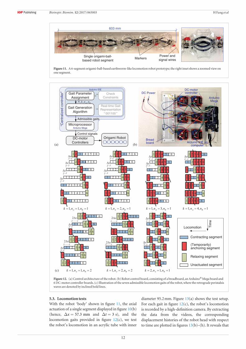
5.2. Robot ‘centralized controller’The earthworm’s locomotion is achieved by coordinated muscular contractions, which mainly exhibit a retrograde peristalsis wave. By mimicking the peristalsis wave, a generic gait algorithm has been developed [21], which could automatically generate gaits (square waves) to control the robot. In a multi-segment earthworm-like robot, four parameters are used to describe the locomotion gait, namely, the number of segments N, the number of driving modules k, the number of anchoring segments during a transition nA, and the number of relaxing (contracting) segments during a transition nR. These four parameters are not independent to each other but have to satisfy the following constraints k n n1, 1, 1A R⩾ ⩾ ⩾ , and
+N k n n2A R⩾ ( ).In this research, the robot ‘centralized controller’
(i.e. a locomotion gait generator) consists of encoded gait generation algorithm in Arduino® Software IDE and an Arduino® Mega hardware. By providing the gait parameters to the controller, admissible locomo-tion gaits are generated. The gait signals are then trans-mitted to the DC-motor controllers to actuate the DC-motors. Figure 12(a) shows the control architecture of the robot, and figure 12(b) displays the photo of the control board. For a 6-segment robot, there are seven admissible gaits, plotted in figure 12(c). If assuming that at each transition step the anchoring segments can firmly anchor with the environment without any for-ward or backward slip, and the relaxing and contract-ing segments can output enough force to push and pull the adjacent segment, the average locomotion speed for each gait can be theoretically predicted as
=− + ∆
∆V
N k n n
N n
x
t,A R
R
( )/ (6)
where ∆x denotes the axial stroke of the robot segment, and ∆t denotes the transition time.
Figure 10. Robot segment performance evaluation. (a) The setup for measuring the robot segment’s deformation, where the segment is fixed on a support, and its deformation with respect to time is recorded by laser vibrometer with sampling frequency 1000 Hz. (b)–(d) Show the measured deformation-time histories of the DC-motor segment, the SMA segment, and the balloon segment, respectively. The actuation period and the actuation amplitude are labelled.
Table 1. Properties and deformation performances of the three robot segments.
Segments
Axial
maximum
length (mm)
Axial
deformation
(mm)
Axial deformation
ratio (deformation/
maximum length)
Weight
(g) Actuator parameters
Actuation period
Other issues
Contract
(s)
Extend
(s)
DC-motor
segment
96.3 57.3 59.5% 34.0 DC gear motor: 12 V
120RPM
3.0 3.0 Relatively
complicated
assembly
SMA
segment
113.5 55.2 48.6% 39.0 Spring wire: Ф
0.381 mm 25coils
4.5 25.5 Heat
insulation
required
Balloon
segment
93.4 55.9 59.8% 16.0 Inflation pressure:
13.8KPa
4.5 5.5 Air sealing
required
Bioinspir. Biomim. 12 (2017) 065003
12
H Fang et al
5.3. Locomotion testsWith the robot ‘body’ shown in figure 11, the axial actuation of a single segment displayed in figure 10(b) (hence, ∆ =x 57.3 mm and ∆ =t 3 s), and the locomotion gaits provided in figure 12(c), we test the robot’s locomotion in an acrylic tube with inner
diameter 95.2 mm. Figure 13(a) shows the test setup. For each gait in figure 12(c), the robot’s locomotion is recorded by a high-definition camera. By extracting the data from the videos, the corresponding displacement histories of the robot head with respect to time are plotted in figures 13(b)–(h). It reveals that
Figure 11. A 6-segment origami-ball-based earthworm-like locomotion robot prototype; the right inset shows a zoomed view on one segment.
Figure 12. (a) Control architecture of the robot. (b) Robot control board, consisting of a breadboard, an Arduino® Mega board and 6 DC-motor controller boards. (c) Illustration of the seven admissible locomotion gaits of the robot, where the retrograde peristalsis waves are denoted by inclined bold lines.
Bioinspir. Biomim. 12 (2017) 065003

13
H Fang et al
under different gait controls, the robot could perform effective locomotion in the tube with significantly different modes. For example, by changing the gait from = = =k n n1, 1, 1A R (figure 13(b)) to = = =k n n1, 1, 2A R (figure 13(f)), the robot’s
locomotion period is reduced to half. Figure 14 show the sequences of video frames of the two cases, from which we notice that with =n 1R , the robot could return to its initial configuration in 18 s; while with
=n 2R , it only costs 9 s for the robot to finish one cycle. Figure 14 also shows that the axially-contracted configuration propagates along the segments to the right (dashed arrows), while the locomotion is toward to the left, which is a representation of the earthworm’s retrograde peristalsis waves.
By measuring the displacement in three peri-ods, the average locomotion speeds are calculated and plotted in figure 15 with solid dots. The theor-
etically predicted average locomotion speeds based on equation (6) are also plotted in figure 15 with empty squares. It reveals that in addition to the locomotion mode, the robot’s average speed can be effectively tailored by gaits. Overall, with more contracting/extending segments, fewer driving modules, and fewer anchoring segments, i.e. with larger nR, smaller k and nA, the robot could achieve higher average speed (see detail analysis and optimization in [23]). With differ-ent gaits, the robot is able to move with a wide range of average speeds, with the minima 3.6 mm s−1 achieved at = = =k n n1, 4, 1A R , and the maxima 12.3 mm s−1 achieved at = = =k n n1, 1, 2A R . Comparing the theoretical predictions with the exper imental meas-urements, they agree well in qualitative trend, as well as the gaits where minimum and maximum aver-age speeds are achieved. Moreover, at those gaits with more than one anchoring segments (i.e. >n 1A ), the
Figure 13. (a) Locomotion test setup. (b)–(g) Show the displacement of the robot head with time, corresponding to the seven gaits generated in figure 12(c). The locomotion periods are denoted by different shades.
Bioinspir. Biomim. 12 (2017) 065003

14
H Fang et al
average speeds have better quantitative agreement; this is because more anchoring segments can provide stronger anchor force to prevent backward slippage (see backward displacements denoted in figure 14), and hence reduce the speed loss. To include such unex-pected slippage of anchoring segments, a dynamic model is required [21].
6. Conclusion and discussion
A novel origami-based earthworm-like locomotion robot is developed and explored in this research. This new innovation combines the structural advantages learned from the earthworms’ morphology characteristics and the benefits originated from origami folding. Among various origami patterns, the origami ball structure stands out because of its cylindrical shape, simple design, and earthworm-like bidirectional deformability. Systematic kinematic analysis reveals that the origami ball is able to achieve large axial and radial deformations in an antagonistic
way, and such bidirectional deformability could be programmed based on requirements by adjusting the number of constituent waterbomb units. Origami ball’s mechanics is also experimentally characterized in this paper. We find that the origami ball possesses multiple stable configurations, and axial actuation can effectively achieve configuration switches among them. Here the multiple stable configurations correspond to the wells of the intrinsic elastic potential stored in facets and creases, because the origami ball partly loses rigid-foldability. On the other hand, we show that the origami ball possesses certain compliance in the radial direction. However, experiments reveal that radial actuation cannot be used for robot development because it is unable to switch the origami ball’s configuration. From the robot development perspective, we demonstrate that the axial multistability and radial compliance of the origami ball offers many advantages in terms of control implementation, robustness, and applicability.
With the knowledge of origami ball’s kinemat-ics and mechanics, we integrate DC-motor, SMA springs, and pneumatic balloon with the origami ball into three designs and prototypes of earthworm-like robot segment. Comparing with certain previously reported earthworm-like robot segments with similar actuations, the origami-based robot segments could surpass them in terms of the axial deformation ratio, mainly because of origami’s outstanding deformable feature. For example, the DC-motor segment (with axial deformation ratio 59.5%) outstrips our previous prototype based on spring-steel-belt body and servo-motor actuation (with axial deformation ratio 31.5% [15]); the balloon segment also shows higher axial deformation ratio (59.8%) than a pressure-based arti-ficial-rubber-muscle segment with axial deformation ratio 22.9% [3]. Then we choose the DC-motor seg-ment for proof-of-concept robot prototyping because of its fast actuation and robustness. A 6- segment
Figure 14. Sequences of video frames for gait (a) = = =k n n1, 1, 1A R and (b) = = =k n n1, 1, 2A R . The retrograde peristalsis waves are denoted on the axially-contracted segment by dashed arrows, and the positions of robot head are denoted by dotted vertical lines. Note that there is some backward displacement when the wave transits from the robot rear to the robot head, denoted by the dotted rectangles.
Figure 15. The theoretically predicted and experimentally measured average speeds at different gaits. The minima and maxima of the average speed are denoted.
Bioinspir. Biomim. 12 (2017) 065003
15
H Fang et al
origami-ball-based earthworm-like locomotion robot is prototyped, which is 220 g in weight and has a very low weight-length ratio of 0.36 g mm−1. This is sig-nificantly lower than certain previous reported earth-worm-like locomotion robots, e.g. 76.0 g mm−1 of the continuous robot based on braided mesh [26], 1.39 g mm−1 of an earthworm-like robot with spring-steel-belt body [15], 1.27 g mm−1 of a servomotor-based underground earthworm-like explorer [13], and 0.92 g mm−1 of a SMA-actuated robot [70]. The low weight-length ratio mainly comes from the light origami structure, which accounts for only 8.7% of the whole robot weight.
In addition to the robot ‘body’, we design a loco-motion gait generator as the robot ‘centralized con-troller’ by learning from the earthworm’s locomotion mechanism, retrograde peristalsis wave. For the 6-seg-ment robot, seven admissible gaits can be generated, controlled by which, the robot can achieve effective locomotion with different modes and average speeds, varying from 3.6 mm s−1 to 12.3 mm s−1. Such mode switches and average speed changes can be achieved simply by adjusting the gait and do not call for adjust-ing the actuations.
The results presented in this paper demonstrate that the origami-based approach can be used to rap-idly fabricate a low-cost earthworm-like locomotion robot. Compared to the traditional robot development process, origami introduces a novel ‘2D patterning—folding’ process to replace the ‘part design—part fabrication—final assembly’ process, which shows unique advantages of increased design customizability, reduced fabrication costs, light weight, scalability, and re-configurability. While with these exciting benefits, further explorations on origami-based robot develop-ment are needed to overcome the current limitations and challenges. For example, small-scale origami fab-rication techniques would need to be developed for miniaturizing the robot size to submillimeter level; incorporating other active materials or actuators with the origami structures is also needed for more compact design.
Acknowledgment
The authors would like to thank Dr Suyi Li, Narayanan Kidambi, Zhen Wu, and Chenghao Wang for the inspiring discussions that were of great benefit to this work. This research was partially supported by the National Science Foundation under award No. 1634545, the University of Michigan Collegiate Professorship, and the University of Michigan Summer Undergraduate Research in Engineering (SURE) program.
ORCID iDs
Hongbin Fang https://orcid.org/0000-0001-6691-0531
References
[1] Yamashita A, Matsui K, Kawanishi R, Kaneko T, Murakami T, Omori H, Nakamura T and Asama H 2011 Self-localization and 3-D model construction of pipe by earthworm robot equipped with omni-directional rangefinder Proc. of the 2011 IEEE Int. Conf. on Robotics and Biomimetics (Phuket: IEEE) pp 1017–23
[2] Kishi T, Ikeuchi M and Nakamura T 2013 Development of a peristaltic crawling inspection robot for 1-inch gas pipes with continuous elbows Proc. of the 2013 IEEE/RSJ Int. Conf. on Intelligent Robots and Systems (Tokyo: IEEE) pp 3297–302
[3] Harigaya K, Adachi K, Yanagida T, Yokojima M and Nakamura T 2013 Development of a peristaltic crawling robot for sewer pipe inspection Proc. of the 2013 IEEE Int. Conf. on Mechatronics (ICM) (Vicenza: IEEE) pp 267–72
[4] Mangan E V, Kingsley D A, Quinn R D and Chiel H J 2002 Development of a peristaltic endoscope Proc. 2002 IEEE Int. Conf. on Robotics and Automation (ICRA) vol 1 (Washington, DC: IEEE) pp 347–52
[5] Glozman D, Hassidov N, Senesh M and Shoham M 2010 A self-propelled inflatable earthworm-like endoscope actuated by single supply line IEEE Trans. Biomed. Eng. 57 1264–72
[6] Cotta F, Icardi F, Zurlo G and Molfino R 2006 Peristaltic locomotion: application to a worm-like robot Climbing and Walking Robots-Proc. of the 8th Int. Conf. on Climbing and Walking Robots and the Support Technologies for Mobile Machines (CLAWAR 2005) ed M O Tokhi et al (Berlin: Springer) pp 501–8
[7] Kassim I, Phee L, Ng W S, Gong F, Dario P and Mosse C A 2006 Locomotion techniques for robotic colonoscopy IEEE Eng. Med. Biol. Mag. 25 49–56
[8] Wang K and Yan G 2007 Micro robot prototype for colonoscopy and in vitro experiments J. Med. Eng. Technol. 31 24–8
[9] Heung H, Chiu P W Y and Li Z 2017 Design and prototyping of a soft earthworm-like robot targeted for GI tract inspection 2016 IEEE Int. Conf. on Robotics and Biomimetics, ROBIO 2016 (Qingdao: IEEE) pp 497–502
[10]Edwards C A and Bohlen P J 1995 Biology and Ecology of Earthworms (London: Chapman and Hall)
[11]Trueman E R 1975 The Locomotion of Soft Bodied Animals (London: Edward Arnold)
[12]Quillin K 1999 Kinematic scaling of locomotion by hydrostatic animals: ontogeny of peristaltic crawling by the earthworm lumbricus terrestris J. Exp. Biol. 202 661–74
[13]Omori H, Nakamura T and Yada T 2009 An underground explorer robot based on peristaltic crawling of earthworms Ind. Robot An Int. J. 36 358–64
[14]Saga N, Tesen S, Sato T and Nagase J-Y 2016 Acquisition of earthworm-like movement patterns of many-segmented peristaltic crawling robots Int. J. Adv. Robot. Syst. 13 1–10
[15]Fang H, Wang C, Li S, Xu J and Wang K W 2014 Design and experimental gait analysis of a multi-segment in-pipe robot inspired by earthworm’s peristaltic locomotion Proc. SPIE 9055 90550H
[16]Jung K, Koo J C, Nam J, Lee Y K and Choi H R 2007 Artificial annelid robot driven by soft actuators Bioinspir. Biomim. 2 S42–9
[17]Daltorio K A, Boxerbaum A S, Horchler A D, Shaw K M, Chiel H J and Quinn R D 2013 Efficient worm-like locomotion: slip and control of soft-bodied peristaltic robots Bioinspir. Biomim. 8 035003
[18]Schulke M, Hartmann L and Behn C 2011 Worm-like locomotion systems: development of drives and selective anisotropic friction structures Innovation in Mechanical Engineering- Shaping the Future, Proc. of the 56th Int. Scientific Colloquium (Ilmenau, Germany) ID 19628
[19]Tanaka Y, Ito K, Nakagaki T and Kobayashi R 2012 Mechanics of peristaltic locomotion and role of anchoring J. R. Soc. Interface 9 222–33
[20]Horchler A D et al 2015 Peristaltic locomotion of a modular mesh-based worm robot: precision, compliance, and friction Soft Robot. 2 135–45
Bioinspir. Biomim. 12 (2017) 065003

16
H Fang et al
[21]Fang H, Li S, Wang K W and Xu J 2015 A comprehensive study on the locomotion characteristics of a metameric earthworm-like robot part A: modeling and gait generation Multibody Syst. Dyn. 34 391–413
[22]Steigenberger J and Behn C 2011 Gait generation considering dynamics for artificial segmented worms Rob. Auton. Syst. 59 555–62
[23]Fang H, Wang C, Li S, Wang K W and Xu J 2015 A comprehensive study on the locomotion characteristics of a metameric earthworm-like robot part B: gait analysisi and experiments Multibody Syst. Dyn. 35 153–77
[24]Fang H, Li S, Wang K W and Xu J 2015 Phase coordination and phase–velocity relationship in metameric robot locomotion Bioinspir. Biomim. 10 066006
[25]Boxerbaum A S, Horchler A D, Shaw K M, Chiel H J and Quinn R D 2011 A controller for continuous wave peristaltic locomotion 2011 IEEE/RSJ Int. Conf. on Intelligent Robots and Systems (San Francisco, CA: IEEE) pp 197–202
[26]Boxerbaum A S, Shaw K M, Chiel H J and Quinn R D 2012 Continuous wave peristaltic motion in a robot Int. J. Rob. Res. 31 302–18
[27]Kim B, Lee M G, Lee Y P, Kim Y and Lee G 2006 An earthworm-like micro robot using shape memory alloy actuator Sensors Actuators A 125 429–37
[28]Kim B and Park S 2005 An earthworm-like locomotive mechanism for capsule endoscopes Proc. of the 2005 IEEE/RSJ Int. Conf. on Intelligent Robots and Systems (Edmonton: IEEE) pp 2997–3002
[29]Qiao J, Shang J and Goldenberg A 2013 Development of inchworm in-pipe robot based on self-locking mechanism IEEE/ASME Trans. Mechatronics 18 799–806
[30]Zarrouk D and Shoham M 2012 Analysis and design of one degree of freedom worm robots for locomotion on rigid and compliant terrain J. Mech. Des. 134 021010
[31]Fang H and Xu J 2014 Stick-slip effect in a vibration-driven system with dry friction: sliding bifurcations and optimization J. Appl. Mech. 81 051001
[32]Seok S, Onal C D, Wood R, Rus D and Kim S 2010 Peristaltic locomotion with antagonistic actuators in soft robotics Proc. of the 2010 IEEE Int. Conf. on Robotics and Automation (ICRA) (Anchorage, AK: IEEE) pp 1228–33
[33]Kim S, Hawkes E, Cho K, Jolda M, Foley J and Wood R 2009 Micro artificial muscle fiber using NiTi spring for soft robotics Proc. of the 2009 IEEE/RSJ Int. Conf. on Intelligent Robots and Systems (St Louis, MO: IEEE) pp 2228–34
[34]Tachi T 2009 Simulation of rigid origami Origami4 ed R J Lang (Boca Raton, FL: CRC Press) pp 175–87
[35]Tachi T 2009 3D origami design based on tucking molecule Origami 4 ed R J Lang (Boca Raton, FL: CRC Press) pp 259–72
[36]Tachi T 2010 Origamizing polyhedral surfaces IEEE Trans. Vis. Comput. Graph. 16 298–311
[37]Deng D and Chen Y 2014 Origami-based self-folding structure design and fabrication using projection based stereolithography J. Mech. Des. 137 021701
[38]Onal C D, Tolley M T, Wood R J and Rus D 2015 Origami-inspired printed robots IEEE/ASME Trans. Mechatronics 20 2214–21
[39]Schenk M and Allwood J 2011 Cold gas-pressure folding of Miura-ori sheets Proc. of Int. Conf. on Technology of Plasticity (Aachen, Germany) pp 1–6
[40]Balkcom D J and Mason M T 2008 Robotic origami folding Int. J. Rob. Res. 27 613–27
[41]Peraza-Hernandez E A, Hartl D J, Malak R J Jr and Lagoudas D C 2014 Origami-inspired active structures: a synthesis and review Smart Mater. Struct. 23 094001
[42]Randall C L, Gultepe E and Gracias D H 2012 Self-folding devices and materials for biomedical applications Trends Biotechnol. 30 138–46
[43]Cavallo F and Lagally M G 2015 Nano-origami: art and function Nano Today 10 538–41
[44]Lebée A 2015 From folds to structures, a review Int. J. Space Struct. 30 55–74
[45]Fang H, Li S, Ji H and Wang K W 2016 Uncovering the deformation mechanisms of origami metamaterials by introducing generic degree-4 vertices Phys. Rev. E 94 043002
[46]Schenk M and Guest S D 2013 Geometry of Miura-folded metamaterials Proc. Natl Acad. Sci. 110 3276–81
[47]Fang H, Li S and Wang K W 2016 Self-locking degree-4 vertex origami structures Proc. R. Soc. A 472 20160682
[48]Silverberg J L, Evans A A, McLeod L, Hayward R C, Hull T, Santangelo C D and Cohen I 2014 Using origami design principles to fold reprogrammable mechanical metamaterials Science 345 647–50
[49]Silverberg J L, Na J, Evans A A, Liu B, Hull T C, Santangelo C D, Lang R J, Hayward R C and Cohen I 2015 Origami structures with a critical transition to bistability arising from hidden degrees of freedom Nat. Mater. 14 389–93
[50]Waitukaitis S, Menaut R, Chen B G and van Hecke M 2015 Origami multistability: from single vertices to metasheets Phys. Rev. Lett. 114 055503
[51]Li S and Wang K W 2015 Fluidic origami with embedded pressure dependent multi-stability: a plant inspired innovation J. R. Soc. Interface 12 20150639
[52]Babaee S, Overvelde J T B, Chen E R, Tournat V and Bertoldi K 2016 Reconfigurable origami-inspired acoustic waveguides Sci. Adv. 2 e1601019
[53]Li S and Wang K W 2015 Fluidic origami: a plant-inspired adaptive structure with shape morphing and stiffness tuning Smart Mater. Struct. 24 105031
[54]Felton S, Tolley M, Demaine E, Rus D and Wood R 2014 A method for building self-folding machines Science 345 644–6
[55]Zhakypov Z, Falahi M, Shah M and Paik J 2015 The design and control of the multi-modal locomotion origami robot, Tribot Proc. of the IEEE Int. Conf. on Intelligent Robots and Systems (Hamburg, Germany) pp 4349–55
[56]Miyashita S, Guitron S, Ludersdorfer M, Sung C R and Rus D 2015 An untethered miniature origami robot that self-folds, walks, swims, and degrades 2015 IEEE Int. Conf. on Robotics and Automation (Seattle, WA: IEEE) pp 1490–6
[57]Lee D-Y, Kim J-S, Kim S-R, Koh J-S and Cho K 2013 The deformable wheel robot using magic-ball origami structure Proc. of the ASME 2013 Int. Design Engineering Technical Conf. and Computers and Information in Engineering Conf. (Portland, OR: ASME) DETC2013-13016
[58]Vander Hoff E, Jeong D and Lee K 2014 OrigamiBot-I: a thread-actuated origami robot for manipulation and locomotion IEEE Int. Conf. on Intelligent Robots and Systems (Chicago, IL: IEEE) pp 1421–6
[59]Onal C D, Wood R J and Rus D 2013 An origami-inspired approach to worm robots IEEE/ASME Trans. Mechatronics 18 430–8
[60]Pagano A, Leung B, Chien B, Yan T, Wissa A and Tawfick S 2016 Multi-stable origami structure for crawling locomotion Proc. of the ASME 2016 Conf. on Smart Materials, Adaptive Structures and Intelligent Systems (Stowe, VT: ASME) SMASIS2016-9071
[61]Filipov E T, Paulino G H and Tachi T 2016 Origami tubes with reconfigurable polygonal cross-sections Proc. R. Soc. A 472 20150607
[62]Lv W, Ma J, Chen Y and You Z 2016 Rigidly deployable origami tubes based on kite-shape pattern ASME 2016 Int. Design Engineering Technical Conf. & Computers and Information in Engineering Conf. (Charlotte, NC: ASME) DETC2016-59506
[63]Chen Y, Lv W, Li J and You Z 2016 An extended family of rigidly foldable origami tubes J. Mech. Robot. 9 021002
[64]Yao S, Liu X, Georgakopoulos S V and Tentzeris M M 2014 A novel reconfigurable origami spring antenna 2014 IEEE Antennas and Propagation Society Int. Symp. (Memphis, TN: IEEE) pp 374–5
[65]Butler J, Morgan J, Pehrson N, Tolman K, Bateman T, Magleby S P and Howell L L 2016 Highly compressible origami bellows for harsh environments ASME 2016 Int. Design
Bioinspir. Biomim. 12 (2017) 065003

17
H Fang et al
Engineering Technical Conf. & Computers and Information in Engineering Conf. (Charlotte, NC: ASME) DETC2016-59060
[66]Lee D-Y, Kim S-R, Kim J-S, Park J-J and Cho K-J 2013 Fabrication of origami structure using pattern enclosed composite (PEC) 2013 13th Int. Conf. on Control, Automation and Systems (Gwangju, Korea) pp 313–5
[67]Chen Y, Feng H, Ma J, Peng R and You Z 2016 Symmetric waterbomb origami Proc. R. Soc. A 472 20150846
[68]Chiang C H 2000 Kinematics of Spherical Mechanisms (Malabar, FL: Krieger Publishing Company)
[69]Yasuda H and Yang J 2015 Reentrant origami-based metamaterials with negative Poisson’s ratio and bistability Phys. Rev. Lett. 114 185502
[70]Wang Y, Song C and Wang Z 2011 A SMA actuated earthworm-like robot Intelligent Computing and Information Science ed R Chen (Berlin: Springer) pp 619–24
Bioinspir. Biomim. 12 (2017) 065003