orion final report - nasa · orion final report nag5-9737 november 22, 2002 prof. robert twiggs ......
TRANSCRIPT

Orion Final Report
NAG5-9737
November 22, 2002
Prof. Robert Twiggs
Stanford University
https://ntrs.nasa.gov/search.jsp?R=20030002459 2018-09-16T12:18:21+00:00Z

,(,Iqmassv a_nlanJ4s ....._(Iqtuassv a_nlanJ4s


EMERALD NANOSATELLITESTANFORD UNIVERSITY - SANTA CLARA UNIVERSITY
ggsniversity
"_,' Emerald Wade Hennlng, June 1999
University Nanosatellite Program Review
http.llssdl.stanford.edulEmeraldl

University Nanosatellite Program Review

EMERALD MISSION
ROBUST DISTRIBUTEDSPAC SYSTEMS
Integration between Multi Spacecraftsand Ground Station Network
Demonstration of Component- and
System-level Technologies
, Colloid Micro-Thruster
Radiation Testbed
buted Computing
• Distributed System Autonomy
• GPS Formation Flying
• VLF Ionospheric Science

Presentation Outline
i_!!!
PAYLOAD AND MISSION OPERATIONS
Freddy [email protected]
SYSTEM AND SUBSYSTEM DESCRIPTION
Sco_ _" "_'rine_k.,el &,ill I I
Julie Townsend
SAFETY, INTEGRATION AND TESTINGEsther Dutton

SYSTEM OVERVI EW
VLF Science
, GPS FFo
II
Ops Autonomy 'Dist Comp
18" hex, 9" x 13" sides
15 kg (each satellite)
AI honeycomb, stackable trays
12 v and 5 v reg. power
120 data & command bus
ga,,_ _ _ , ^ m.............. :,...L:-.-11_:5 I-VVllt:t _IUWt:ti ;_VVIL_IIIII_J
telemetry
0
9600 baud half-duplex comm. with
circular polarization
2-axis magnetic stabilization
Drag panel position control
GPS relative positioning
COllOID MICRO-THRUSTER
TECHNOLOGY OVERVIEW
Simple, Efficient Electrostatic Acceleration of
Charged Droplets
EMERALD MISSION
Survival of the T_.., .,.+,,, e...-+,,._,I I I/U_._Lt_;I _.,lyOL_I I I
Operational Test Firing- Output Stream Measurement
Technology Demonstration- Supporting Traditional Spacecraft Attitude Control
- Supporting Distributed Space Systems Formation
Flying Control

Thruster System
Dual-Polarity ThrusterExpect 0.1 mN Thrust, --1000 sec Isp
0.5 kg, 10 cm x 10 cm x 20 cm
4 Watts max, no-power @ standby
ElectronicsPIC 16F877 for Thruster Control and Data Sampling
Data sampling module developed by CDH
Stream output sensor (picoammeter) at 20 kHz sampling at8 bit, for 30 sec
EMCO High-Voltage +/- 6kV Power Supply
Insulin Pump as Propellant Storage and Delivery
Current propellant choice: Sodium-Iodide / Glycerol

Thruster SystemEMERALD 12C Bus
TIM
i
PlCmicro P _e
Ii_co ntroller i._controller !A rj
J +HVPS i -HVPS
__
1/L.---.--_" l//
\ /./
RADIATION TESTBED
OBJECTIVE• Evaluate effects of radiation on micro electronics
EMERALD MISSION
° Measures Single Event Effects
Single Event Upsets (bit-flip)
Single Event Latchup
Measure Total Ionizing Dose
- Dosimetry
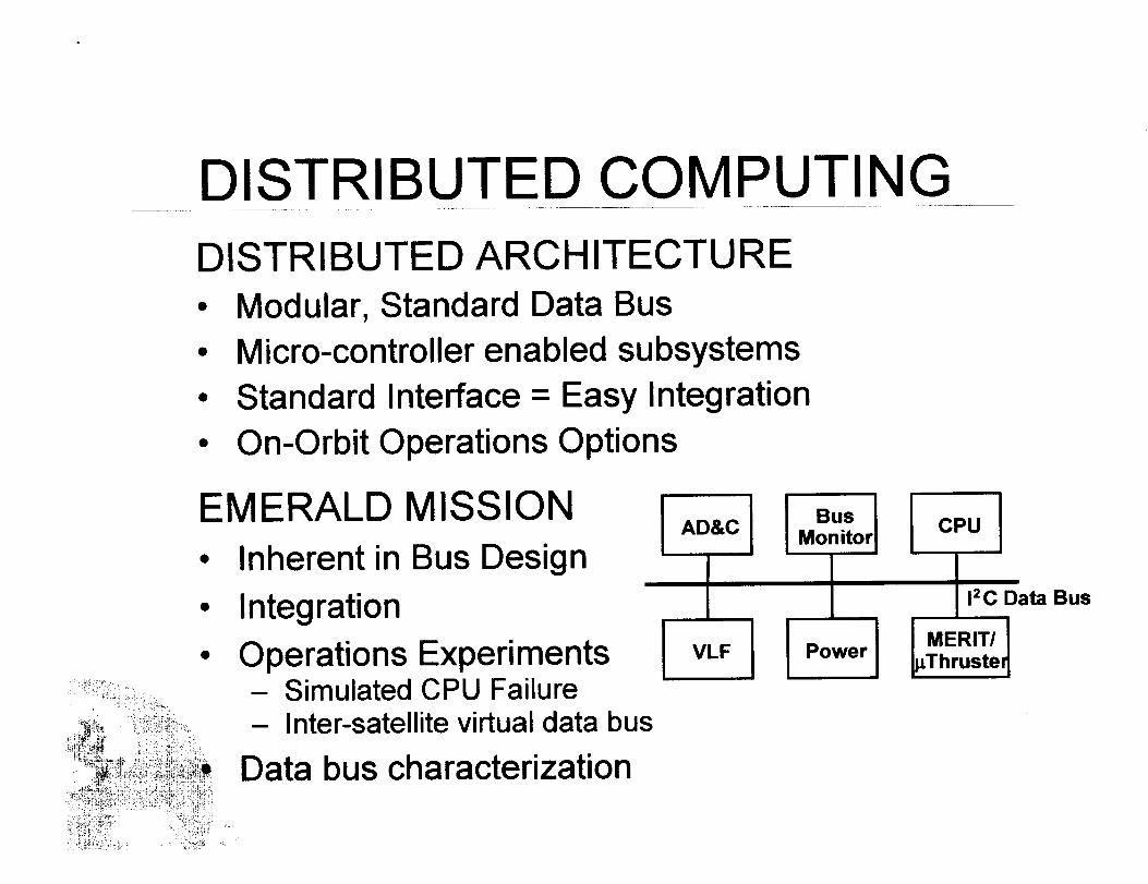
DISTRIBUTED COMPUTING
DISTRIBUTED ARCHITECTUR
Modular, Standard Data Bus
Micro-controller enabled subsystems
Standard Interface = Easy Integration
On-Orbit Operations Options
EMERALD MISSION
Inherent in Bus Design
Integration
Operations Experiments- Simulated CPU Failure- Inter-satellite virtual data bus
Data bus characterization
AD&C
VLF
BusMonitor
Power
CPU
12C Data Bus
MERITI
Thruster
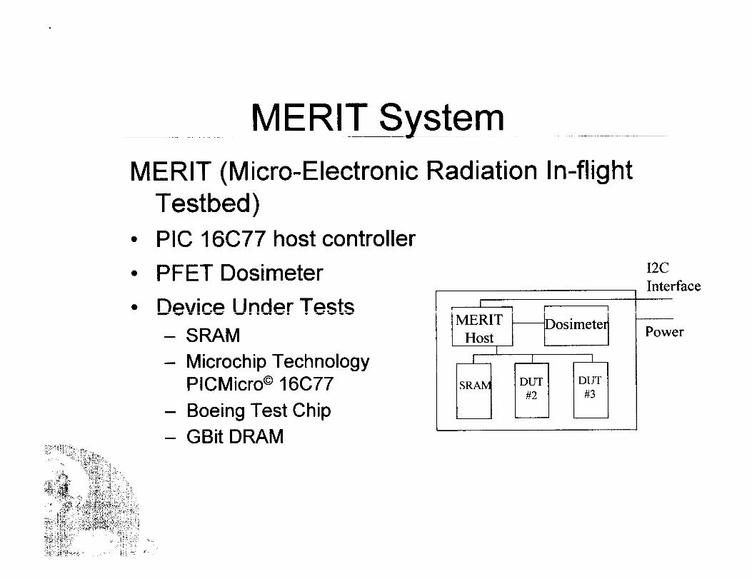
MERIT System
MERIT (Micro-Electronic Radiation In-flightTestbed)
° PIC 16C77 host controller
• PFET Dosimeter
Device Under Tests
- SRAM
- Microchip TechnologyPICMicro © 16C77
- Boeing Test Chip
- GBit DRAM
I
MERIT
HostI
I2C
Interface
Power

Dist. Comp. ComponentsCommon Interface• PIC 16F877 Microcontroller
"Library" Software: A to D, Memory, 12C, RealTime, etc.
_CP3J12C Serial Data Bus
Bus MonitorTo CPU
0.15 kg, 6 cm x 18 cm x 2.5 cm
100 mW, always on (except "Safe" mode)
PIC 16F877, serial (SPI) EEPROM
Direct Comm. Link- Simple 1200 Baud Modem- Enabled by unique bit code

00
i
0
_.______eJ[--]-_--_.lM-I, SelleO_ sn8
0
O.
i
X
0
rn
%
I

DISTRIBUTED SYSTEM AUTONOMY
AUTONOMOUS OPERATIONS
Distributed Beacon
Advanced Science Execution
Reactive Ground-based Navigation Control
EMERALD MISSION
• Autonomous Operations Experiments supporting
Distributed Space Systems Architecture

Distributed Beacon
OBJECTIVE
• Multi-satellite beacon monitoring for satellite-to-satellite and fleet-level cases
DESIGN
Telemetry filter assesses satellite health
Assessment (a few bits) periodically broadcast
Ground network automatically notifies operator
Heavy reliance on heritage

Advanced Science Execution
OBJECTIVE
• Evaluate fleet-level control capability and
"opportunistic" science data collection
DESIGN
Fleet-level control:
relay time-tagged commands
Opportunistic Science:Threshold filter to recognize periods of interest
Incorporated into VLF system

Ground-based NavigationOBJECTIVE
Automatic calculation and transmission of
navigation commands when on-orbit relativenavigation system is off (power, failures, range,
etc.)
DESIGN
• Beacon indicates on-orbit status
FreeFlyer navigation software on ground
Mercury program executes commanding
Primarily a ground-based system

GPS FORMATION FLYING
OBJECTIVE
• Provide a comprehensive on-orbit demonstration of
true formation flying spacecraft
EMERALD and EMERALD-ORION MISSION
° Demonstrate virtual spacecraft bus technologies
• CDGPS for real-time navigation sensing and fleetcontrol
° Demonstrate various control architectures and a real-
time inter-vehicle communication link and local
ranging systems

Formation Flying ExperimentControl for a cluster of microsats
Real-time autonomous control software
Formation directed at a high-level from the ground.
CDGPS Receiver
2 Antenna
Expect better than 1 m (relative - radial) for positiondetermination
Expect better than 5 m (relative - radial) for control
Low-power, low-cost, attitude capable GPS receiver

GPS Receiver & PIC Controller
ICP DATA
ORION CMDS j
\7
X/LINK
EMERALD GPS RECEIVER/CONTROL UNIT
' ii lCPDATA
I
GPS
I ARM60 ]
PIC
p
D/PANEL CMDS
RS232
I D/DRAG PANELS
CPU

VLF IONOSPHERIC SCIENC
SCIENTIFIC GOAL
Thunderstorm monitoring and ionospheric science
through the reception of lightning-induced VLFwaves using multiple spacecraft
A I I_I_IEMER_-D MISS '''_'
Lightning Count Survey
Science to Demonstrate and Validate Distributed
Space Systems

VLF Receiver SystemVLF Receiver
Active Filter and Amplifier
- Peak amplificationat 5kHz
Threshold detector
- Triggers comparatorto count strikes above
a programmed level
VLFReceiver
I Ili_ ThresholdDetector
VLF SubsystemProcessor
__1__ 1
L J L
Power
12C Interface
PIC ProcessorSample VLF receiver data and store to science memory
Read science memory and send out data through 12C Bus
Science Data Tagging (Time, Attitude, Absolute andRelative Position)

MISSION OPERATIONS
MAJOR MODES OF OPERATIONS1. Launch and Verification
2. Stacked Flying3. Stack Separation
4. Distributed Operations5. Non-Distributed C_n_r_tions
V p_lP V | _IL _ m
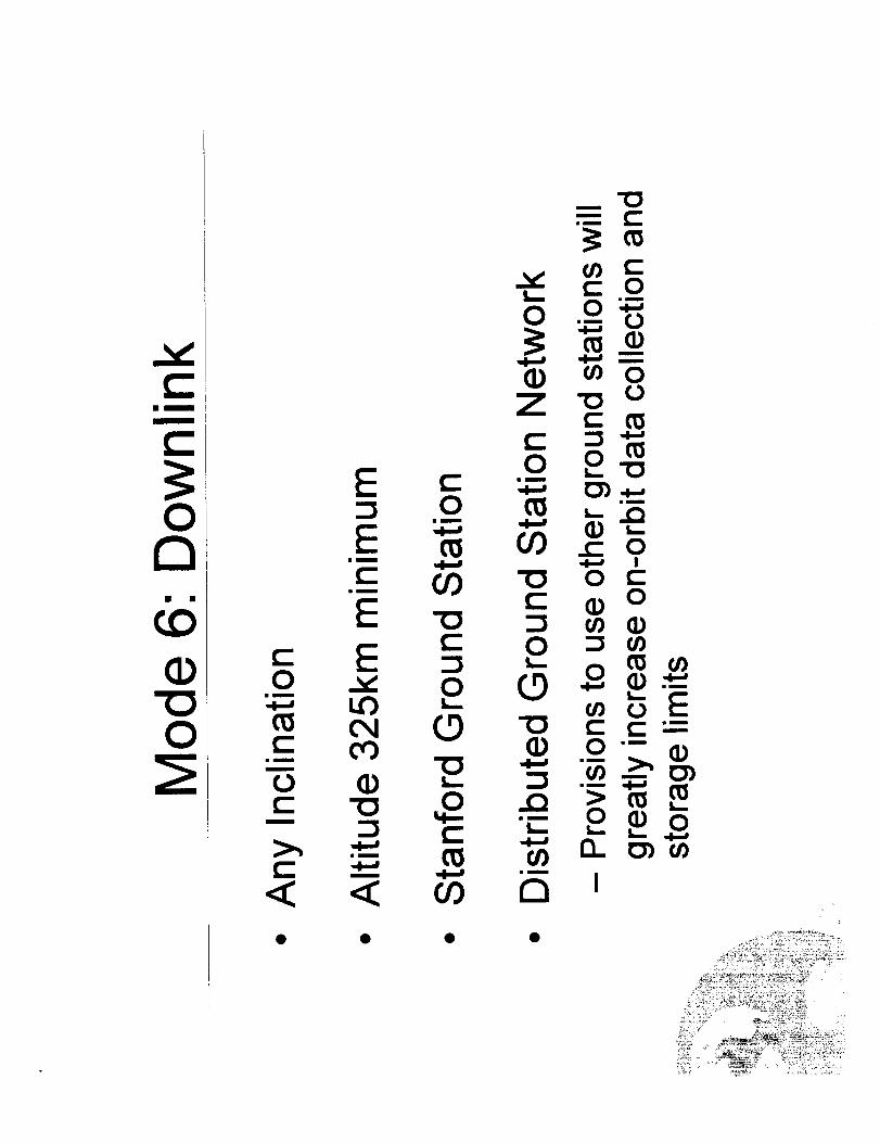
6. Downlink
7. Safe Mode
Driving RequirementsShuttle Requirements
MSDS and SHELS Requirements
System Resources

Mode 1: Launch and Verification
Launch from Space Shuttle
- Separation controlled from Shuttle
- Emerald will be powered off while on Shuttle
Initial Acq_Ji._itinn
- Power turned on when separated
- Use beacon or orbital data to acquire satellitefrom Ground Station
- Ground Station command to initiate Emerald
system boot-up

Mode 2: Stacked Flying
Emerald satellites will orbit forundetermined time stacked
- Time between Shuttle separation and satellite
separationh_ _ffif, ,ri_ r_n, ,ir_m_nf_May be ,_m_÷..,4-- III I II il, lk,._'_,_il
downlink access and/or waiting for Orion
Perform System Checks
Can Run Experiments

Mode 3: Stack Separation
Short but Critical operational mode
Separation initiated from Ground Station
- While in an optimal pass
Satel"'",,L=o_,_u'-"_"'de _,,,,,cal
- Driven by Experiment and MissionRequirements

Mode 4: Distributed Operations
Experiments that require adequate satellitecross-link and relative position knowledge
- Distributed Computing
- Distributed System Autonomy
- EMERALD Formation Flying
EMERALD/ORION Formation Flying
• ORION with 1 Emerald
• ORION with 1 Emerald, Emerald responds to ORION
Multi-Spacecraft VLF Experiment

Mode 5: Non-Distributed Operations
Experiments that can be run independentof the other satellite
- Colloid Micro-Thruster
• Test Firing
• Attitude Control Experiment
• Formation Control Experiment
- Radiation Testbed
- Single-Spacecraft VLF
llI
I
8
0
_. "0-- e-llI

Mode 7: Safe Mode
Emerald to revert to Safe Mode during
periods of low power or immediately uponexperiencing an on-orbit anomaly
- Only critical subsystems left on, all,mlna,e_,experiments te- " _ ,4
- Health and Maintenance Monitoring (HMM)
subroutine will perform checks on all systems
and experiments
- HMM Information to be sent over beacon
Ground Station(s) will use beacon to diagnose
and correct problems

Iil
O0
GO
<
Iii
II!
>,O0
0
C
c-O
"0c-
I,,..
!,.,-
GO
E
O0
ECD
I--
E
o0
017
,,I..,,J
U)
• lira
m
c'-
"0C
"0C
E-E0
ECDr_>.,,O0
c-O
ilm
ilm
C
EE0
ro
r_>.,,
O0
-6I,,...
C0rO"0C
CO
iiim
Ciim
E!,,.,,.
r7CD
"0
elm
<!:

Structure DesignHeritage design
Aluminum honeycomb hex
plates & side panels
Longerons- Stainless steel all-thread,
aluminum spacers
• L-brackets
Layout
Subsystem boxes as
,essary

(Di--
0
tL__
III _lmlllm
>
0")0")0')
tO(DICIC0
(DE<<CO<Z
C
Enm
I,,,-
Q)
XUJ
EQ)
(/).Q
O0
C"mm
m
O_
I-- _--Q) _o_ _ co
N
0
O _J
@ r4
C0
L_
O}Im
c-O0
C
c'_
(].)"0mm
C/)
>-. ,,<- .,..,
.Q "1__> ,
(D _"O__ E mm
(f) 0 Q..._,..'"0
Q.) t" --- ,__
N
0
A
0
in
0
>.,tOC
!,,--
I,,--
Z
N
A
X(1)
"0
Bm
0
0C
O-
4-.-
L_
7
i.

Vibration Testing
Natural Frequency in X dir. = 53 Hz.
I ACC_:0,0142 g Drive:0,0000 V-p_ Loop:Closed " J"_'lI DispI:0-06940 u in p-p Totld 1-mw:00:07:09 Checks Fmtal_led ,5 lyre. ,X
t Freq:1996.02 IEt Sweep No,:0 [UP]
miemm_km___m___la ...
•_.OF-_.----:.=_.........=._.-_-4..... :.-.=.-..:.._ ........................... _........ =-..=:.,.:.::::::.:..: .-.._ ..... ::::::: :::::_ :;: _ ::::::::::::::::::::::::::
..... : ==============================================================...... 5:.:..: ....... :::i.:.i....:L:.:.:.:;....:....-.'. -'5: !::5:5:!.::::5!5::::}5::5!:::_:- ..........................
.............. 4-........... }.......... ' ' -"""i'", ....................... _................ ? ......... t ........ ".'...... ?"'"'""_""_"', ..........................
.^ ..... _:__!: ....... "................ _"_ i '_!!,_i....... _........_ 4-------E b----_---:--_-!_,_:/1_".....
ol
,oom 2__:__L__2_L*4....... L___i____ ....
• 20.0 _ i00.0 ..... .OK 2.OK
Frequency, Hz
10:EO:_O1AMTwl _ 2291 81he Ir_mp X.dlreclkm e_mmrl_ 4' 1
1-==i,.. I,l_lm_

"----1E ......
ZH 'kouenb_J..4
)40_ "A O I, 0"OOL
¢_ueuu_JnsealN .'._TU_._lnseolN :l.},uauuoJnseolN
Idfll O:'ON cle_S ZH gle'L66L:l_Jd
: _/_ /_ _ Z"}_ "_ p,lqqmj3:._o.e, qZ ) £g:90:OO:ewlj. #11%.o.,i. d-d u, n 6_ogo'o:lCl_O
p_SOIO:O0Ol _Id-A O000"O:e^PO § COLO'O:I _°_g'
@
6u!Is )Iuo!leJq!A

Vibration Testing
Nat%al Freauencv in Z dir. = 106 Hz.Total Tlme:O0.'06:63 Chedm:Enalded
r-_a_7._ _, s.,_ .o.:0 [up; ot.tc
Mem_urementl; MeasurementS- Measurement3
100.OL-'::.. ............................................................. 1_ ............................................................ ; 'i ........ _---T ......................... :__.
_:!! ............ _ .......... , ........ :-..--:---v---,-.-.,- - L .................. _' :.: :-:.--:_: ....... _,....... ::::::::::::::::::::::::::::::::::::::::::::::::::::
: .... : 1" . :1
1o o ..-....-....-..._..... 4 -.d= _.=.g.----> .---:+...... .-..=..... -- ...... E--.-.-...gg._:_.=.=..+.._=-.e i
!>!>!>¢¢!:_::: a!5a!::_!!!::-5!!55!_:5=.!!!!5!5_:_57555555557557z!2!5!saa!55!55N25555!55_5:!_!!{5!!!55:!:_!>::::!4ii!2;{ii17{ili_;ii;iii_iiiiiii=i-:-:2_
"; !_================================================================================!7!7_........._::........_!......._;_"_!:_::>i:::::::_:::_:::::::::::!'" !::!:_!::_!_:_!_:_:_:_:}!_:_:_._!!!_:!!_}}}_{_!_._!_._.:._)!_.{_.{:._.!::!!!{:.!!_.!_:!_'-!{!'_:':':::_:"::7:!.!{!!}!':':_!!'-!."-_!!i::._i{!_:..!!!/': '-i
10.0_
- : ...........,.........--r :: i " ! ........... -.............:........!......._............... r............................... - ........... : ........ 7 ...... 7" _! : ] ....
: . . . t...................... , . ! { __ ......,.............................: _ : : ..
" ' I : ! : : ! i
.0 100.0 1.0K 2.0K
Frequency, Hz

(6u!pueq 'uo!sseJdwoo) seoejJa_U! _sod/uo]_nq leouaqds
(6u!puaq 'uo!ssaJdwoo) seoepelu! euoo/lOlS-A E
(Jee4s 'uo!sJo),)seoe_ue),u!euoo/dno
(JOSUSS peol 4]!M) JO},OeJ)_eEI/Jaqo)_eO ]1o8
(elqe_es-eJ ulw _) JO},enpv ]nu_lMb S_SJE},S
wels/_s uo!leJedes

Separation System Mechanisms
_:.-..::--':.. •
Bolt Retractor/Catcher
Starsys Qwknut Actuator
II

Drag Panel Mechanism DesignLinear Actuator
System
Linear Guides
on Drag panels
Rigid Hinges
i !!_i_
,_,,,_,_,_,.,_,__i_,,,_i_!_!i_' _

VLF Antenna Mechanism Design
,\
3 meter long,1/2" widecarpenter's tape
Reverse TapeMeasureMechanism- Coiled tape's
tendency to expandoutward drives it
- Pin Puller Actuators

Structure and Mech. Status
Development status
- Engineering model components manufactured
- Engineering model intersatellite separation systemcomplete (minus springs)
- Drag panel prototype & actuator selection underway
- VLF deployment mechanism prototyped
- Actuator circuits prototyped
Outstanding structural issues
- Natural frequency

Thermal Analysis
Preliminary "back-of-envelope" calculations- Assumed single node, steady-state, worst-case
- Hand calculations and spreadsheet
- Results: ~ 10 °C to 50 °C
I-DEAS FEM Thermal Analysis Package- 36 node model
- Industry mentors
- Expect results in 1/00

Thermal Design & Test
Planned passive compensation techniques
- Thermal coatings
-Insulation
- Modification of conductive paths
Planned testing
- Rudimentary in-house component level tests
- System-level thermal-vacuum test• Lockheed Martin
• Target date 11/00

Power Design
Generation and Storage
- Spectrolab triple-junction Ga As solar cells
- Two 8-cell strings per panel
- 9.3 W average power
- 10 5AH Sanvo CADNICA NiCd Batten/w
Power Regulation and Distribution
- Regulated 12V and 5V using Vicor Regulator
- Unregulated 11-14V Battery Voltage
- Dallas 1-Wire serial bus for Power Switching
lemetry
Voltage and Current Telemetry via Dallas 1-Wire

Power Diagram w/Inhibits(8 solar panels)
_ I
+
power bus(hazardous loads)
o
o =,t-0r"
V
Inhibits _r mission success
Power Status
Regulation circuitry
- Prototype complete
- EM PCB being manufactured
Batteries in-house
Solar Panels
- Layouts designed
- First fabrication meeting with Spectrolab 1/00

C&DH DesignCPU
- SpaceQuest V53 Based• 10MHz Processor
• 6 Built-In Serial Channels
• 1MB EDAC RAM
• Built-In HNV to support SNV TNC
Operating System- BekTek OS
• RAM-based file system
• Multi-tasking and multi-user
• Includes S/W for TNC using AX.25
• Includes H/W and S/W Debugging Utilities
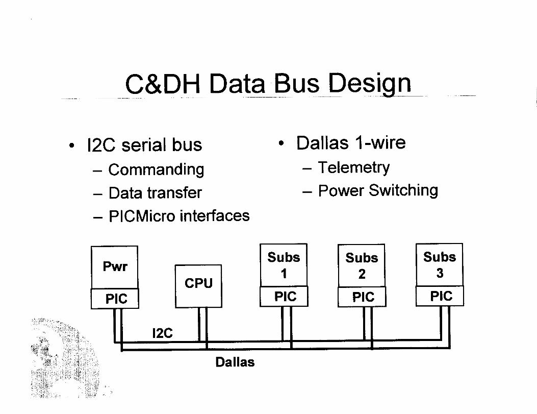
C&DH Data Bus Design
12C serial bus
- Commanding
- Data transfer
- PICMicro interfaces
Dallas 1-wire
- Telemetry
- Power Switching
P_/r
PICCPU
Subs1
PIC
Subs2
PIC
Subs3
PIC
12C
Dallas

C&DH Status
PICMicro
- Visual Basic testing
Main CPU
- First EM in-house
suite (CoolTools TM) - Functional testing inBus and functionality progress using ARTIClibraries created for board and EM
subsystem use • Also...
Software
- Architecture laid out
- Dependencies defined
Integration withcommunications
system has begun
Development
underway

Communications Design
Transmitter- 437 MHz- Hamtronics kit °
(SAPPHIRE heritage)- Modified to transmit
at multiple power •levels
Receivers- 437 MHz and 145
MHz (backup)- Hamtronics kit
(SAPPHIRE heritage)
SpaceQuest modem
SpaceQuest softwareTNC
Circular antenna
polarization
Beacon based on
Sapphire heritage
- On/Off keyed status
report of vehicle

II
(J0
I
rn
03
I
I- I 0

Communications Status
• Architecture and hardware finalized
EM transmitter and receiver- Assembled and tested
- Successfully communicate _,..h.,,...n_,,.,v._,,.,.t_t_mnl i_r_
Isolation/polarization circuitry- Prototypes complete- EM PCB being manufactured

Attitude Determination
, .....
Requirement: 10 deg, 1 deg/sec
Light/IR sensor (SAPPHIRE heritage)
- Array of phototransistors
- On/off or linear analog differential configuration
Honeywell HMC2003 3-Axis Magnetic Sensor
ODDSS (Virtual Sun Sensor)
- Estimates sun angle via solar panel currents
Dedicated PICMicro ® for onboard signal
processing

Attitude Control
Requirement: 15 deg (vel. dir.), 3 deg/sec
Magnets & hysteresis rodsSized for separation orientation
Designs and sizing techniques L,oo=u v,,SSDL/Amsat heritage
Aerodynamic drag stabilization- VLF antennas and drag panels
- Sized to dominate magnetic torques
Colloid thruster option

ADCS Status
Behavior simulations via STK
Determination hardware in-house
Circuit & PICMicro ® prototyping underway
Magnets sized
• Additional drag body TBD

Safety, Integration, and Test
Safety- hazards
- hazard controls
-inhibits
Integration
- satellite integration
- stack integration
-interfaces
- ground equipment and servicing
Test

Emerald Safety
Power Subsystem
Hazards
- Hazard
• NiCd batteries
° provides power to deployable mechanisms andcommunication subsystem
- Hazard Controls
• battery box design (leakage, inadvertent short)
• trickle charge mode prevents batteries from overcharging
• switches to prevent solar power from reaching batteries
-Inhibits
• four independent and verifiable inhibits to prevent powerfrom reaching hazardous loads
• external port for inhibit verification
• inhibit control tied to stack separation signal

Emerald SafetyHazards
Microthruster
Hazards
• high voltage power supply
• liquid propellant
• thruster misfire
Hazard Controls
• systems are discharged and off while on MSDS
• clearance around power supply impedes arcing
• very low-pressure propellant tanks
• inert and stable propellant (Nal/Glycerol)
• full testing of materials and assemblies to confirmstructural integrity, material characteristics, etc.
• not enough thrust for recontact with Shuttle

Emerald SafetyHazards
Communication Subsystem- Hazard
• inadvertent RF transmission
Hazard Controls
• maximum transmission levels well below limits
Inhibits
• two inhibit "requirement" satisfied by power subsystem
Command/Control Subsystem- Hazard
• EMI
......_- Hazard Controls• worst-case interference is 20 MHz
• boxes shield noise from MSDS and Space Shuttle

Emerald SafetyHazards
Structure and Mechanisms
- Hazards
• structural failure
• inadvertent deployment of mechanisms
- Hazard Controls
• full analysis and testing to show compliance withstructural integrity requirements
• full documentation of design, analysis, test, assembly,
and integration
• deployment actuators will not function without power
• actuators can be treated as structural members (no
credible failures)

¢DCO
¢D0
121
¢q
,UDraft SIVRL
Phase 2 Review
_D
_D
_D
l_Update Safety_D£cj
A
V SDP, SIVP, FCP, mat. list
CPR Inputs !

Safety Documentation
Deliverables
- Flight Safety Data Package (22210 FSDP)
• will comply with the following generic Hitchhiker payload
hazard reports:
-"Damage to STS Electrical Systems"
-"Electromagnetic Interference with Space Shuttle
Operations"
-"Ignition of a Flammable PLB Atmosphere"
-"Flammable Materials"
-"Failure of Hitchhiker Payload Structure"
• other hazard reports
- deployable mechanisms
,_,, - battery leakage/rupture
t

Safety Documentation
Deliverables (cont.)
Structural Integrity Verification Plan (SIVP)
• will report mass properties in English and metric units
• will include Fastener Integrity Report and FractureControl Plan in SIVP
Fracture Control Plan (FCP)
• pressurized system fracture control (microthruster)
• fracture control of mechanisms
• transportation and load points
• no composites

Safety Documentation
Deliverables (cont.)
- Ground Safety Data Package (22220 GSDP)
• will comply with generic Hitchhiker payload hazard reports forGround Support Equipment (GSE)
-"Structural Failure of Ground Lifting/Handling Equipment
(GHE)"
-"Inadvertent Movement of Payload or GSE"
-"Electrical Shock"
-"Electrical Failure Causes Fire"
-"Purge Pressure System Failure" (if needed)
- "Use of Hazardous Materials/Substances" (RTV)

Safety Documentation
Deliverables (cont.)- Materials List
• will report mass properties in English and metric units
• will submit Material Usage Agreement for all non-standardm_t_ri_lc:
- no non-standard materials have been identified thus
far
- possible exception: Nal/Glycerol propellant
- materials checked against MSFC-HDBK-527 (via
MAPTIS)
- critical fasteners will chosen from GSFC stock
- many fasteners exempt from requirements

Emerald Integration
Part 1
- integration of subsystems into Beryl andChromium
Pa_ 2
- integration of Beryl and Chromium into Emeraldstack
Part 3
integration of Emerald stack with MSDS

Emerald IntegrationPart 1 Flow
Mechanical
Assembly
Power
Verification
C&DH/12C
System Verification IS yCstemmm vnercfa_otnSn ___
_.1 Primary/Secondary _[ Experimental Systems ]_ ADCS System L_Structure Assembly Verification Verification
__1 Functional/Sequence ]TestThermal Cycling &
Thermal Vacuum Tests t Helmholtz Chamber [_.Test
_ I Functional/Sequence ] _Test

Emerald IntegrationPart 1 Documentation
21110 Nanosatellite Assembly Document- structure
- power/electrical
- thermal
,.,_,_m i,-_÷i,_ _-,_mrn=nrl =nd rl=t=h=n_!jngw,, ,,, ,un o, ,.,,,.,,,, ,,, ,,.,,,..,--- IVqI_,.,_iLI _,,.olu I 'q.auql.,_,i_,.,q.A .m,q,m m"vm
- guidance, navigation, and control
- payload/experiment
- safety
Assembly logs included in 21110

Emerald IntegrationPart 2 Flow
Mechanical
Assembly
Power
Verification
C&DH/12C
System Verification "_S yCstemmm vnercfa_otnSn I--
_.t Primary/Secondary _._[ Experimental Systems t_ ADCS System I,Structure Assembly Verification Verification
--_ Functi°nTI/Stquence tRandom Vibration
Test---,-I,
Sinusoidal Vibration
Test
Functional/SequenceTest
Shock Test ],

Emerald IntegrationPart 2 Details
Stack Integration
assembly of Emerald to be performed at Stanford
- microthruster propellants will be loaded atStanford
- assembly logs at satellite and stack level
- satellites shipped without charged batteries andwith inhibits in place
- manufacturing processes documented prior to
assembly
assembly teams trained in handling proceduresand fabrication skills

Emerald IntegrationPart 2 Documentation
21100 Stack Assembly
- assembly logs included in 21100
21120 Intersatellite Separation Systr
21200 Stack interfaces
- mechanical interface
- electrical interface
- ground support equipment interface
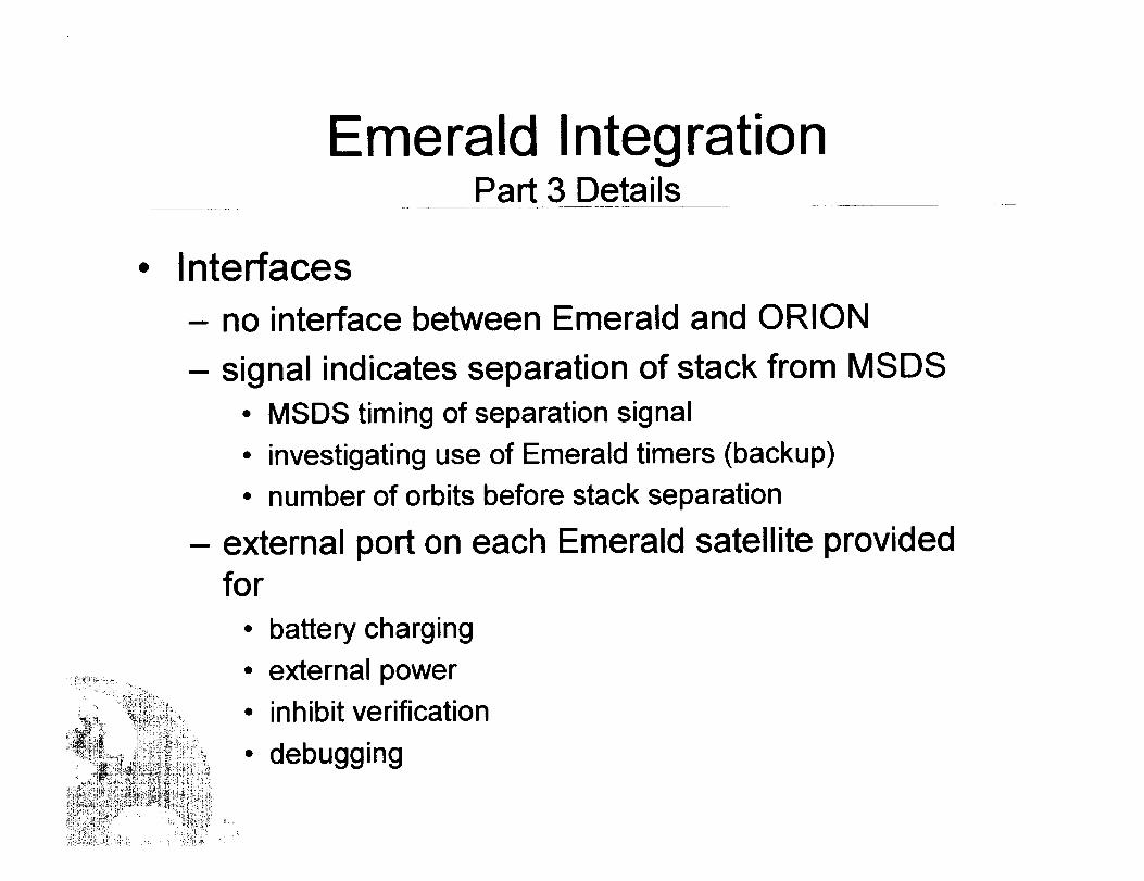
Emerald IntegrationPart 3 Details
Interfaces
- no interface between Emerald and ORION
- signal indicates separation of stack from MSDS
• MSDS timing of separation signal
• investigating use of Emerald timers (backup)
• number of orbits before stack separation
- external port on each Emerald satellite providedfor
• battery charging
• external power
• inhibit verification
• debugging

Emerald IntegrationPart 3 Details (cont.)
@ Ground Equipment and Servicing
-load points
• currently designed for dual handles attached to the top ofthe stack through four load bearing members
• willing to accommodate any ground handling equipment
_y_,,.,,,o, etc. _.a,, be .,..,.._....4 to '_" _"'" '""'_ ""_""-- C_ILLCllt_,I I_;t_i LI I_ I_JPUI IVC_IU _./_./11 IL_'.'_
• no special requirements for equipment

Emerald IntegrationPart 3 Details (cont.)
Ground Equipment and Servicing
- battery charging
• trickle charging method
• 10 hour charge time
• 0.5 A charge current
• i6.5-i7 V charge voitage
• can be accomplished at Goddard or KSC
• no on-orbit battery charging prior to MSDS separation
- propellant
• no need for fueling or de-fueling at Goddard or KSC
• propellant will be stable during transport and delays

Mechanical Test Plan
Strength analysisSinusoidal Sweep Vibration analysis
required 7002Random Vibration
AcousticsSelf-Induced Shock
Externally-Induced Shock
Modal SurveyPressure Profile
Appendage Deployment
required 7002
Stanford
lanalysisNASA AmesNASA Ames
I _nalysisNASA Ames
NASA Ames
NASA Ames
required 7002 required 7002America West
NASA Ames NASA Amesi i
Stanford Stanford
Dec 1999 - mass model sine sweep, random vibe
Jan 2000 - mass model externally induced shock
2000 - component and appendage testing
mer 2000 - stack testing

Thermal Test Plan
ThermalNacuum Thermal Cycle Stanford
Ambient Pressure Thermal Cycle iStanfordThermal Balance
Temperature-HumidityBakeout
Leak Test (sealed components)
StanfordStanford
Loral
Loral
Loral
Loral
,,,=
Loral
Loral
Early 2000 - EM thermal tests at Loral or LMMS
Testing to verify thermal model in IDEAS

EMI Test Plan
Conducted Emissions
Radiated Emissions IStanford !Stanford!Conducted Suscep!ibility I i_....Rad=ated Suscept=b=l=ty !StanfOrd, Stanford
Power off prior to MSDS separation, noconducted susceptibility

Functional Test Plan
Electrical Interface StanfordStanfordStanford
Stanford Stanford/AFRLStanfordComprehensive Performance
FaUure-free Performance Stanford
Mechanical Interface Stanford StanfordJ , , ,
Calibrations Stanford Stanford
Stanford
Stanford
End-to-End Compatibility Tests & Mission SimulationsLife Test
"-"" Properties '"_':""':""IVId_ V _1 II IVl,.oClLIt,.& I I |1 I I llmt I
i
Stanford/AFRLi, , ,L, i , i
Stanford
analysis

r_ O0 Q.
Draft SIVR
Phase 2 Review
Update Safe_Doc j
._ CDR
¢ _ Phase 0/1 Review ]m
o,------_ Saf_ TIM
4, Payload Safety Conf.
o---_ ,STP Visit ,L
SDP, SIVP, FCP, mat. list
Finalize Test Sequence ] _,
CPR Inputs ]

0(:3¢,4 o
_1_"_ Locked Operations[---
Env.Tests Done]

i,
r
0
mmmmmm
L_
0
,.41--w
C_
c_L,--
E
"0
-dL,..
04-=
c'-C_
m
"Oc_c_
Q.,4...m
¢