orion lm-100 liquid laundry supply dispenser
TRANSCRIPT

P/N 20-07287-00 Rev. D © Hydro Systems Company, Inc. 2014 HydroSystemsCo.com Toll Free: 1.800.543.7184 1
Reference Manual ORION LM-100 Series
Preface
This manual has been written and illustrated to present the basic installation, operation, and servicing instructions of the ORION LM-100 Liquid Laundry Supply Dispenser. Guidelines will be suggested in reference to the preferred method of installation, however, the variety of equipment and the surrounding environment will dictate the actual installation of the LM-100.
ORION LM-100 Liquid Laundry Supply Dispenser
Online and downloadable Product Manuals and Quick Start Guides are available at www.HydroSystemsCo.com Please check online for the latest version of this Reference Manual.
!WARNING:The ORION LM-100 dispensing system is intended to be installed by experienced installers, in accordance with all applicable electrical and plumbing codes.
NOTE: Always use proper lockout tagout procedures when installing and servicing dispensing systems. Please disconnect all washer and dispenser power sources any time the dispenser cabinet is open.
All dish machine and dispenser power must be disconnected during installation and/orany time the dispenser cabinet is opened.

P/N 20-07287-00 Rev. D © Hydro Systems Company, Inc. 2014 HydroSystemsCo.com Toll Free: 1.800.543.7184 2
Table of Contents
1 Theory of Operation ..............................................................................................................................3 2 Mechanical Installation Principle of Operation ......................................................................................................................4 3 Installation and Setup Preplanning the Installation ..............................................................................................................5 Controller Installation .......................................................................................................................5 Machine Interface Install ...............................................................................................................5-6 Supply Trigger Wiring .......................................................................................................................6 Trigger Signal Wiring Notes.....................................................................................................6 Pumpstand Mechanical Installation .................................................................................................6 Pumpstand Electrical Installation .....................................................................................................7 Flush Manifold Connection (optional) ..............................................................................................7 Suppy and Discharge Tubing ........................................................................................................7-8 Setup and Operation ........................................................................................................................9 Controller Programming Variations .........................................................................................9 Calibrate Pumps .....................................................................................................................9 4 Troubleshooting Troubleshooting Basics ..................................................................................................................10 Circuit Breaker Reset ............................................................................................................10 Trigger Signal Test .................................................................................................................10 Repair Procedures ................................................................................................................10 Troubleshooting Table ....................................................................................................................11 5 Maintenance and Repair Maintenance ..................................................................................................................................12 Tube Replacement ................................................................................................................12 Tube Lubrication ...................................................................................................................12 Repair .............................................................................................................................................12 Disassembly ..........................................................................................................................12 Pump Motor Assembly Replacement ...................................................................................12 Power Wiring (for all Pump Interface PCBs) .........................................................................13 ORION 2 PI Power Wiring .....................................................................................................13 ORION 8-Pump PI Motor Replacement and Power Wiring ..................................................14 Washer Wiring-Contacts for Manufacturers ..................................................................................14 Spare Parts Listing ....................................................................................................................15-16 6 Specifications and Warranty Specifications.................................................................................................................................17 Limited Warranty ............................................................................................................................17 Limitation of Liability ......................................................................................................................17 Index

P/N 20-07287-00 Rev. D © Hydro Systems Company, Inc. 2014 HydroSystemsCo.com Toll Free: 1.800.543.7184 3
Theory of Operation
OverviewThe ORION LM-100 liquid laundry product dispensing system uses the latest technology to providelow cost and reliable operation with full features. The ORION system is designed for laundrymachines typically found in an On Premise Laundry (OPL) type account. Multiple modes of operationallow for maximum flexibility in washer application.
FeaturesThe ORION system features include:• High Capacity Pumps - ORION pumps have an output of up to 18 ounces per minute for fast product transfer.• Six Product Capability Standard - The ORION system is capable of dispensing up to 6 products with a flush manifold. When using a TOTAL ECLIPSE Controller and the optional 8-pump PI PCB, the system can dispense up to 8 products.• Flush Capacity - When used with an STANDARD ECLIPSE Controller or a TOTAL ECLIPSE Controller, a programmable output is available for controlling a flush manifold water valve. Flush time is easily programmed in seconds. A flow switch input is provided as a safety interlock to stop pumps in the event of no (or low) water flow.• Quick Pump Tube Change - The pump faceplates are secured with four finger-tightened, captive thumbscrews to facilitate easy maintenance.• Safe Wiring - The ORION dispensing system requires high voltage connections only at the Machine Interface (MI) to washer signal connections. All other wiring is plug-in with ethernet type communication cables. Dispenser power is sourced from a 115VAC wall outlet or via conduit for 208-230VAC.

P/N 20-07287-00 Rev. D © Hydro Systems Company, Inc. 2014 HydroSystemsCo.com Toll Free: 1.800.543.7184 4
Mechanical Installation
Principle of OperationThe Machine Interface connects to the Controller and communicates a supply signal, derived fromthe laundry machine programmer, at predetermined times in the wash formula. Once a signal isreceived, the ORION dispenser injects specific products directly from their containers to the laundrymachine. See Figure 1 “ORION LM-100 Liquid Laundry Dispensing System Diagram” below toview these components.
Typically, there should be at least three supply signals from the laundry machine for completeautomatic control of each product.
The Machine Interface, installed outside the laundry machine control wiring area, receives the laundrymachine supply signals. It automatically adjusts for supply signal voltages ranging from 24-240VAC or22-24VDC.
The Pumpstand is wired into the appropriate voltage power supply. It also supplies low voltagepower to the Controller and provides an interface for the optional Flush Manifold.
The Controller indicates which formula is currently selected. The laundry operator can change formulasto match the load, review the load counter for each of the formulas, and—if required—primeeach of the pumps from the Controller. Compatible controllers include the STANDARD ECLIPSE and the TOTAL ECLIPSE. An optional 8-pump PI PCB is available for use with an TOTAL ECLIPSE Controllerto yield 8 pump capability. For additional Controller features, please refer to the specific ReferenceManual provided with that Controller.
The Optional Flush Manifold—not shown—provides an alternative means of chemical transfer tothe laundry machine. In flush configuration, the Orion system is a complete, integrated water flushchemical dispensing system.
Figure 1 ORION LM-100 Liquid Laundry Dispensing System Diagram
Standard Eclipse Controller
Total Eclipse Controller

P/N 20-07287-00 Rev. D © Hydro Systems Company, Inc. 2014 HydroSystemsCo.com Toll Free: 1.800.543.7184 5
Installation and Setup
Preplanning the InstallationThe following factors should be considered when choosing aninstallation location:• Locate Pumpstand within 50' (15.3 meters) of the laundry machine,
close to product containers and at a convenient height for pump tube servicing, typically 4–5 ft. (1.2–1.5 meters).
• The Pumpstand must be mounted to a solid surface. Use appropriate hardware for each material, e.g. metal anchors in cement or cinder-block.
• For flush installations, allow room underneath Pumpstand for a flush manifold, water valve, and related plumbing.
• Verify that there is access to the appropriate power source for the unit. For pumpstands with 115VAC motors, locate the power cable close to a suitable 115VAC electrical outlet. Higher voltage
connections must be done in accordance with applicable electrical codes.
• The outlet supply tubing run should not exceed 50' (15.3 meters). The total input and output tubing runs should be kept to less than 60' (18.3 meters) or pump tubing durability will be affected.
Controller InstallationThe Controller should be installed in a suitable location on (or close to) the washer. The location should allow easy access for machine operators to input formulas and to read the display. When utilizing the Auto Formula Select feature (AFS) the Controller can be mounted with or near the pumpstand.
The Controller may be mounted on a horizontal surface, such as the top of the washer, or on a vertical surface, such as the front of the washer.
Machine Interface InstallationMounting the Machine Interface (MI)
Figure 2 Machine Interface (Front and Back)
Mount MI outside the laundry machine control wiring area.
1. Remove lock nut on MI 1/2 inch nipple to secure MI to washer.2. Route MI signal wires through 1/2 inch knock-out on washer (within the wiring area.)3. Reinstall lock nut.4. Route J2 cable to controller.5. Plug J2 cable into Machine Interface.6. Bundle excess J2 cable outside the washer.7. Connect the other end of the J2 cable into the J2 connector on the Controller.
CAUTION:These installation, operation and servicing instructions are for use by qualified personnel only. This pumpstand is intended to be installed by experienced installers,in accordance with all applicable electrical and plumbing codes.
All machine and dispenser power must be disconnected during installation and/or any time the dispenser cabinet is opened.
NOTE:Specific Controller installation instructions are provided in the Controller Reference manual that is shipped with each Controller.
WARNING:Disconnect power to the wash machine before proceeding.
Keep Machine Interface and communication cable away from high voltage wires and relays. NEVER parallel the cable with high voltage lines.
NOTE:Electrical wiring connections for supply triggers should be done inside the junction box. See “Supply Trigger Wiring” (below) for connection information.

P/N 20-07287-00 Rev. D © Hydro Systems Company, Inc. 2014 HydroSystemsCo.com Toll Free: 1.800.543.7184 6
Installation and Setup
Machine Interface Installation (continued)Signal VoltageThe Machine Interface will work with any signal voltage between 24 – 240VAC or 22 – 24VDC. With DC signals, polarity must be observed. Common is negative. The signals should be positive voltages.An optional 12VDC Machine Interface, p/n 03-07902-012, is available and is sold separately.
Supply Trigger Wiring1. Identify the washer supply signals. Check with technical service or with the washer manufacturer if you
are not sure of the connections.2. Use appropriate terminal connectors to connect the signal wires to the Machine Interface wires. Use the
color codes for equivalent pump numbers as found in Table 1 “Signal Wire Connections” on page 7:
Table 1 Signal Wire Connections
Trigger Signal Wiring Notes:• If washer has a single common, wire nut together all Machine Interface common wires that will be used. Tape off or wire nut unused wires.• If one or more pump/pump group signals are not used, they do not need to be connected.• If you are triggering more than one pump from a single washer signal, connect all of the Machine Interface pump signal wires for those pumps to that washer signal.• Each of the 6 LEDs on the MI will light when the corresponding valid signal is received.
Pumpstand Mechanical Installation
Figure 3 Pumpstand Mounting Options
For units with 3 or more pumps and keyhole slot mounting:1. Mark mounting surface screw locations, using the keyholes in the back of the unit as a template. See Figure 3.2. Drill marked locations and install wall anchors that are suitable to the installation surface.3. Start screws into the wall anchors and hang the pumpstand.4. Tighten screws.
CAUTION:Always verify all voltage sources with a meter.
Supply Signal Signal Common Pump Number
Signal 1 Black wire White/Black Pump 1
Signal 2 Brown wire White/Brown Pump 2
Signal 3 Red wire White/Red Pump 3
Signal 4 Orange wire White/Orange Pump 4
Signal 5 Yellow wire White/Yellow Pump 5
Signal 6 Blue wire White/Blue Pump 6

P/N 20-07287-00 Rev. D © Hydro Systems Company, Inc. 2014 HydroSystemsCo.com Toll Free: 1.800.543.7184 7
Installation and Setup
Pumpstand Electrical InstallationIf pumpstands motor voltage is 115VAC, power is sourced from a 115VAC wall outlet. Higher voltageconnections must be done in accordance with applicable electrical codes.1. Connect the J1 Cable to the J1 connector on the Controller.2. If pumpstand motor voltage is 115VAC, connect power cable to the nearest suitable 115VAC wall outlet. In cases where the dispenser must be hard wired from the washer or other power source, consult the wiring label inside the dispenser Pumpstand cabinet.
NOTE: ORION pumpstands have a resettable circuit breaker on the underside of the unit, nextto the power cable.
Flush Manifold Connection (optional)The flush manifold wiring connector is located on theunderside of the pumpstand (Orion 2 pumpstand is shown atright). Specific flush manifold installation instructions areprovided in the Flush Manifold Reference Manual that isshipped with each flush manifold.
Depress the locking tab on the Pumpstand flush jumperharness (connected to flush connector on non-flush units)and remove the jumper harness. Connect flush manifoldconnecting cable to the Pumpstand flush connector.
Supply and Discharge TubingNOTE: The tubing between the pumps and the washing machine should be routed in a descending path from the pumps to the machine.
Supply tubing is not included with the dispensing system. Use thelargest ID (inner diameter) size possible to maximize pump flow rates and minimize pump tube wear.
Do not exceed 50 feet total (pump inlet and exit lengths) combined supply tubing length, or a 10 foot maximum vertical rise.
The ideal situation to minimize any product drip at the washer is to have the supply tube sloped upwards to the washer entry point. If this ideal situation cannot be realized, then form a service loop in the supply tube as close as possible to the washer entry point. This willminimize drip at the injection point at the washer.
NOTE: Installations without a service loop in the tubing risk excessive detergent overshoot.
Figure 4 Pumpstand Flush Connector
CAUTION:Misconnection of the flush manifold solenoid valve and flow switch wires can causedamage to the printed circuit board and/or flow switch.

P/N 20-07287-00 Rev. D © Hydro Systems Company, Inc. 2014 HydroSystemsCo.com Toll Free: 1.800.543.7184 8
Installation and Setup
Supply and Discharge Tubing (continued)The supply tubes can be brought into the washer via the washer’s built in powder supply compartment,or through a side entry port, if available. The latter option may be preferred because it usually addsproduct to the water, not on top of the load. If you add through top mounted compartments, use theController’s delay feature to allow the washer to fill before adding product.
Use tie wraps or hose clamps to ensure that the tubes are secured at the washer entry point.
Figure 5 Supply and Discharge Tubing Installation
1. Connect supply tubes to pump tubes by sliding the supply tube up inside the pump tube. For 3/8" tube you may need to lubricate the supply tube.2. Secure tube connections with tie wraps. (See Figure 5.)3. Place the liquid chemical containers in a suitable area and run 1/4" (6 mm) polyethylene tubing from each container to the pump intake—left—side of each pump tube.4. Insert the supply tubing 1/2" into the pump tube and secure with a tie wrap.5. Insert the other end of the tubing into the tube guide cap and tube guide at the product drum pickup point. While the use of tube guides and caps is optional, this helps to keep tubing in the product and avoid curling (see Figure 5).
NOTE: When using optional, modified-output pump tubes, use 3/8" (9mm) supply tubing.

P/N 20-07287-00 Rev. D © Hydro Systems Company, Inc. 2014 HydroSystemsCo.com Toll Free: 1.800.543.7184 9
Installation and Setup
Setup and OperationRefer to the Controller reference manual for Controller operating and programming instructions. Afterprogramming the controller, test system operation:• Prime each pump and observe the pump tube for any bulging or pulsing on the outlet side (indicating that excessive back pressure is present).• Calibrate pumps and program formulas.• Select a formula, start washer, and observe a test load to ensure all products dispense only when they should.
CAUTION: Always wear eye protection when working with strong or hazardous chemicals.
Controller Programming VariationsControllers that can be used with the ORION system include the STANDARD ECLIPSE and the TOTAL ECLIPSE. While these controllers have some similarities, the information below notes some important variations. Please read this section prior to programming your controller.
Calibrate PumpsNOTE: Refer to your Controller’s Reference Manual to determine the proper calibrationmethod (timed or volume) for your Controller.
You must calibrate all pumps, via the Controller, using either the volume or timed methods of calibration.If you do not calibrate a pump properly, your pumped amounts could be wrong or the pump maynot run. Calibrate pumps using either of the methods below:1. Pumping the exact 8 oz. or 250 ml amount called for in the Calibrate menu instructions (STANDARD ECLIPSE Controller).2. Measuring the precise volume pumped for a 20 second period. When using the timed method, the measuring container must be capable of holding the amount of product that the specified pump is capable of delivering in 20 seconds. (Both methods available on the TOTAL ECLIPSE Controller)
P/N 20-07287-00 Rev. D © Hydro Systems Company, Inc. 2014 HydroSystemsCo.com Toll Free: 1.800.543.7184 10
Troubleshooting
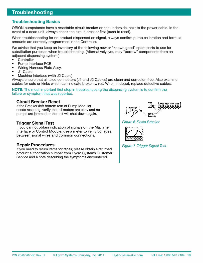
Troubleshooting BasicsORION pumpstands have a resettable circuit breaker on the underside, next to the power cable. In theevent of a dead unit, always check the circuit breaker first (push to reset).
When troubleshooting for no product dispensed on signal, always confirm pump calibration and formulaamounts are correctly programmed in the Controller.
We advise that you keep an inventory of the following new or “known good” spare parts to use forsubstitution purposes when troubleshooting. (Alternatively, you may “borrow” components from anadjacent dispensing system.)• Controller• Pump Interface PCB• Wiring Harness Plate Assy.• J1 Cable• Machine Interface (with J2 Cable)Always ensure that all telco connectors (J1 and J2 Cables) are clean and corrosion free. Also examinecables for cuts or kinks which can indicate broken wires. When in doubt, replace defective cables.
NOTE: The most important first step in troubleshooting the dispensing system is to confirm thefailure or symptom that was reported.
Circuit Breaker ResetIf the Breaker (left bottom rear of Pump Module)needs resetting, verify that all motors are okay and nopumps are jammed or the unit will shut down again.
Trigger Signal TestIf you cannot obtain indication of signals on the Machine Interface or Control Module, use a meter to verify voltages between signal wires and common connections.
Repair ProceduresIf you need to return items for repair, please obtain a returned product authorization number from Hydro Systems Customer Service and a note describing the symptoms encountered.
Figure 6 Reset Breaker
Figure 7 Trigger Signal Test

P/N 20-07287-00 Rev. D © Hydro Systems Company, Inc. 2014 HydroSystemsCo.com Toll Free: 1.800.543.7184 11
Troubleshooting TableUse the following table as a guide to solve system problems.
Troubleshooting
Symptom Possible Solution Action
Dead unit. No display on Controller.
1. Check AC Power Source. Is outlet live? Is Pumpstand plugged in? 1. Restore AC Power.
2. Check if circuit breaker on Pumpstand is tripped.
2. Reset circuit breaker (on underside of pumpstand.
3. Check Controller to Pumpstand wiring. 3. Reconnect or replace J1 cable.
4. Possible defective Pumpstand PI PCB. 4. Replace Pumpstand PI PCB.
5. Possible defective Controller. 5. Replace Controller.
No pumps run onprime or on signal.
1. Check flush connector for contact closure. 1. Reconnect wiring harness.
2. Check for disconnected or damaged J1 cable connections. 2. Reconnect or replace cable.
3. Check for defective PI PCB or Controller. 3. Substitute components, one at a time.
Some (not all) pumps do not runon prime or on signal.
1. Check for loose motor wire connections.
1. Reconnect loose motor wire connections.
2. Check for disconnected or damaged J1 cable connections or for defective PI PCB or Controller.
2. Reconnect or replace cable. Substitute components, one at a time.
All pumps prime OK, but one ormore pumps do not run on signal.
Note: If more than two pumps areprogrammed to run simultaneously,they will be “queued” to run one after another.
1. Check Machine Interface to Controller cable and connections.
1. Reconnect or replace J2 cable. Check and replace MI or Controller.
2. Confirm Pump Calibration. 2. If pumps are not calibrated, calibrate pumps.
3. Check Controller programming. Is it set for Event Mode? Is Pump Interlock on? A re pumps calibrated? Does formula call for non-zero qty? Does formula call for delays?
3a. Reprogram Controller to Timer Mode. Check other settings as needed.
3b. If all checks okay, reset Controller by depowering. If not successful, replace Controller.
4. Verify if valid signal is present by watching Machine Interface LEDs during washer operation or measure with meter.
4a. Confirm signal lasts longer than programmed Signal Filter Time.
4b. If LEDs light, check MI/Controller communication using “Trigger Status” menu in Controller’s program mode.
4c. If no LEDs, check supply trigger wiring or troubleshoot washer for no signals. If signals OK, replace MI.
Pump runs but noproduct pumped.
1. Check pump tube. 1. Change pump tube.
2. Check for input tube air leaks. 2. Change input tube or fittings.
3. Check if product is too viscous and/or if tubing run is too long. 3. Remedy this condition.
4. Check for clogged pickup tube. 4. Clear clog.
Not counting loads.1. Check if the count pump (last/highest number) programmed non-zero pump runs?
1. Reprogram washer supply signals and/or Controller formulas.

P/N 20-07287-00 Rev. D © Hydro Systems Company, Inc. 2014 HydroSystemsCo.com Toll Free: 1.800.543.7184 12
MaintenancePump tubes should be replaced regularly. Many different factors effect tube life, including chemicalcompatibility, pumping pressures (size of supply tubes and distances pumped), time and operatingconditions. Try to replace pump tubes before they fail and leak chemical into the pump housing.Periodically, wipe soil from housings, pump housings, etc. with a damp cloth.
Tube Replacement1. Loosen the four captive thumbscrews and remove pump front cover.2. Remove old pump tube. If tube was broken, clean out residual chemical with a damp cloth.3. Position the roller assembly so it is at a 1:00 / 7:00 orientation. Place left end of tube in housing.4. Rotate roller assembly clockwise as you push the tubing into the housing. This will aid the insertion of stiff or large tubes.5. Lubricate tubing, if needed, with appropriate lubricant (as listed below) for your tube type.6. Replace pump front and tighten captive thumbscrews.
Tube LubricationNew tubes for the peristaltic pumps may be lubricated lightly with the appropriate lubricant. Excessivelubricant will cause premature tube wear. Use the correct lubrication for your tube type.
RepairCAUTION: The ORION pumpstand may contain a variety of PI PCBs. When replacing a pump motor or rewiring power, make certain that you have identified BOTH the type of board and the voltage specific to your installation.
Disassembly1. Remove screws along top of the pumpstand cabinet and allow the front plate to hinge downward.2. To remove the front plate and pump/motor assemblies, disconnect the motor plug connector from the Pump Interface PCB and disconnect the plate ground wire.3. Remove two Phillips-head security screws (at front plate hinges) and lift plate off of end cap “hooks.”4. Loosen four captive thumbscrews to remove the pump front cover. Gently remove pump tubing.5. To remove pump spinner assembly, loosen set screw and slide spinner off of motor shaft. (For reassembly, note the location of the set screw in relation to the flat portion of the motor shaft.)6. The pump rear and motor are secured to the cabinet front plate with four patch-lock, Phillipshead screws. Remove the four screws and lift the pump rear over the motor shaft.7. Remove the pump motor from the backside of the front plate.
Pump Motor Assembly Replacement1. To replace or add a motor (add a pump assembly to an empty pump location), plug the motor wires into the appropriate locations in the motor plug connector for that pump position, according to the Pump Interface PCB that is installed.2. Install pump motor and pump rear, making sure to use the four new patch-lock, Phillips head screws that are provided with the new pump motor.3. Continue assembly by reversing the order of the disassembly steps from the previous section.
Maintenance and Repair
Tube Type Lubrication
Santoprene, EPDM, Viton Silicone lube
Silicone Silicone or Vaseline-type lube
C-Flex No lube

P/N 20-07287-00 Rev. D © Hydro Systems Company, Inc. 2014 HydroSystemsCo.com Toll Free: 1.800.543.7184 13
Power Wiring (for all Pump Interface PCBs)IMPORTANT: Depending upon your Pump Interface PCB, the power wiring terminal positions mayvary. Use only the wiring diagram for the PI PCB that is appropriate to your installation. See the photosand wiring diagrams for each board (Figure 5, Figure 6 and Figure 7) to assist you in identifyingyour board type and using the appropriate wiring diagram.The jumper configurations on the power terminal block determines the input voltage setting.100-120VAC (inclusive) for all PI PCBs1. Connect power to terminals 1 and 4.2. Connect a jumper between terminals 1 and 2 and another between terminals 3 and 4.200-240VAC (inclusive) for all PI PCBs1. Connect power to terminals 1 and 4.2. Connect a jumper between terminals 2 and 3.
CAUTION: Motor voltage rating of installed motors MUST match power wiring configuration!
ORION 6-Pump PI Power Wiring
Figure 8 Orion 6-Pump Wiring Diagrams (115VAC and 208/230VAC voltage specific)
ORION 2 PI Power Wiring
Figure 9 Orion 2 Wiring Diagrams (115VAC and 200-230VAC voltage specific)
Maintenance and Repair
P/N 20-07287-00 Rev. D © Hydro Systems Company, Inc. 2014 HydroSystemsCo.com Toll Free: 1.800.543.7184 14
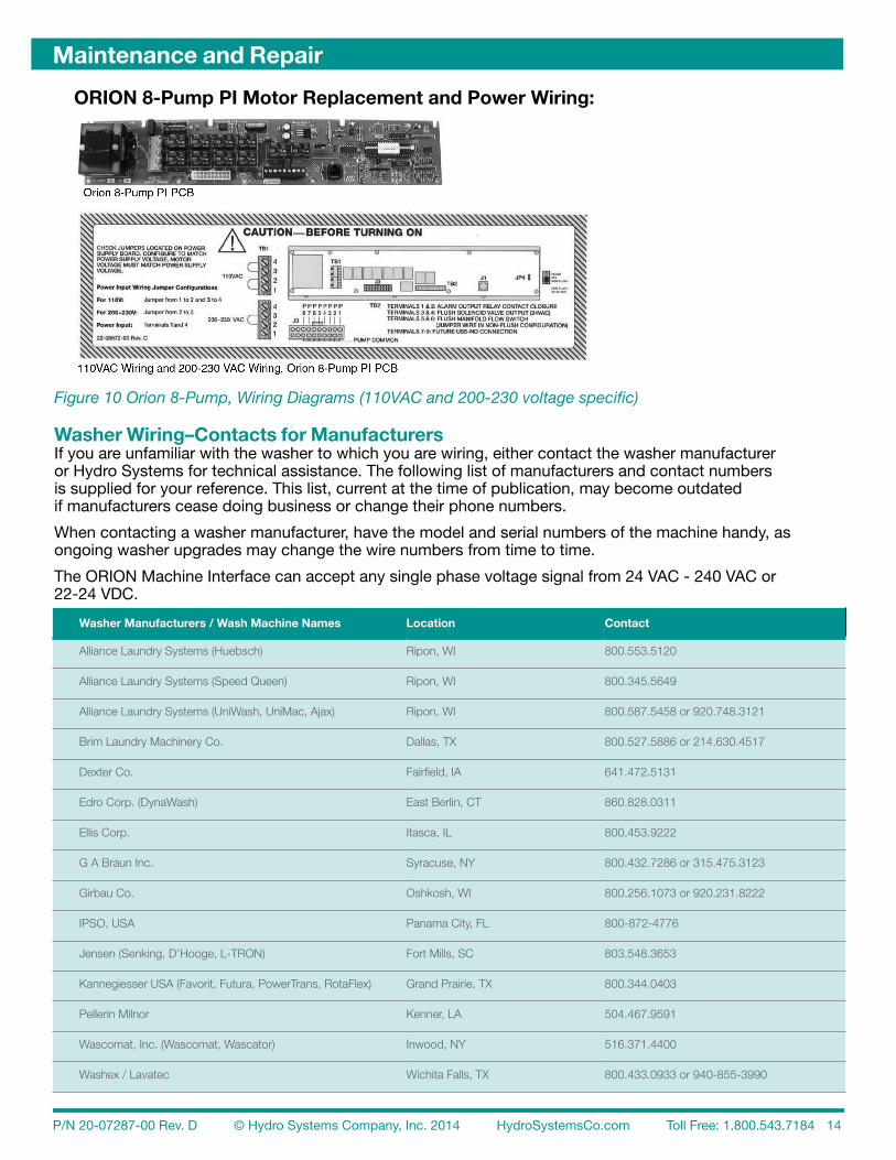
ORION 8-Pump PI Motor Replacement and Power Wiring:
Figure 10 Orion 8-Pump, Wiring Diagrams (110VAC and 200-230 voltage specific)
Washer Wiring–Contacts for ManufacturersIf you are unfamiliar with the washer to which you are wiring, either contact the washer manufactureror Hydro Systems for technical assistance. The following list of manufacturers and contact numbersis supplied for your reference. This list, current at the time of publication, may become outdatedif manufacturers cease doing business or change their phone numbers.
When contacting a washer manufacturer, have the model and serial numbers of the machine handy, asongoing washer upgrades may change the wire numbers from time to time.
The ORION Machine Interface can accept any single phase voltage signal from 24 VAC - 240 VAC or22-24 VDC.
Maintenance and Repair
Washer Manufacturers / Wash Machine Names Location Contact
Alliance Laundry Systems (Huebsch) Ripon, WI 800.553.5120
Alliance Laundry Systems (Speed Queen) Ripon, WI 800.345.5649
Alliance Laundry Systems (UniWash, UniMac, Ajax) Ripon, WI 800.587.5458 or 920.748.3121
Brim Laundry Machinery Co. Dallas, TX 800.527.5886 or 214.630.4517
Dexter Co. Fairfield, IA 641.472.5131
Edro Corp. (DynaWash) East Berlin, CT 860.828.0311
Ellis Corp. Itasca, IL 800.453.9222
G A Braun Inc. Syracuse, NY 800.432.7286 or 315.475.3123
Girbau Co. Oshkosh, WI 800.256.1073 or 920.231.8222
IPSO, USA Panama City, FL 800-872-4776
Jensen (Senking, D’Hooge, L-TRON) Fort Mills, SC 803.548.3653
Kannegiesser USA (Favorit, Futura, PowerTrans, RotaFlex) Grand Prairie, TX 800.344.0403
Pellerin Milnor Kenner, LA 504.467.9591
Wascomat, Inc. (Wascomat, Wascator) Inwood, NY 516.371.4400
Washex / Lavatec Wichita Falls, TX 800.433.0933 or 940-855-3990

P/N 20-07287-00 Rev. D © Hydro Systems Company, Inc. 2014 HydroSystemsCo.com Toll Free: 1.800.543.7184 15
Spare Parts Listing
Maintenance and Repair

P/N 20-07287-00 Rev. D © Hydro Systems Company, Inc. 2014 HydroSystemsCo.com Toll Free: 1.800.543.7184 16
Maintenance and Repair
Reference Number Part Number Description
1 03-03609-02 Machine Interface Module, with J2 Cable
* 03-07902-012 Machine Interface Module, 12 VDC
2a 01-0890-00 Controller, Total Eclipse
2b 01-05970-00 Controller, Eclipse, US Units
* 01-05970-01 Controller, Eclipse, Metric Units
3 13-03213-1000 Circuit Breaker, 10 amp
4 40-06266-00 Flush Jumper Harness (for non-flush installations)
5 37-03105-00 Pump Rear, Standard
* 37-03105-01 Pump Rear, Modified
6 03-03157-01 Pump Spinner, Standard
* 03-03157-02 Pump Spinner, Modified
7 03-03156-01 Pump Front, Standard, w/ Captive Screws
* 03-03156-02 Pump Front, Modified, w/ Captive Screws
8 13-06723-10 Pump Tube, Santoprene, 12 oz., 10-pack
* 13-04273-23110 Pump Tube, Santoprene, 18 oz., 10-pack
* 13-07971-10 Pump Tube, Silicone, 12 oz., 10-pack
* 13-07972-10 Pump Tube, Silicone, 18 oz., 10-pack
* 13-04273-33110 Pump Tube, EPDM, 18 oz., 10-pack
* 13-06724-10 Pump Tube, Viton, 12 oz., 10-pack
* 13-07976-10 Pump Tube, Viton, 18 oz., 10-pack
* 13-06720-10 Pump Tube, EPDM, Modified, 10-pack
* 13-07786-10 Pump Tube, Silicone, Modified, 10-pack
* 13-07982-10 Pump Tube, Santoprene, Modified, 10-pack
* 13-07977-10 Pump Tube, Viton, Modified, 10-pack
9 13-03206-01 Pump Motor, 115 VAC, 60 Hz
* 13-03206-02 Pump Motor, 230 VAC, 50 Hz
* 13-03206-03 Pump Motor, 208 VAC, 60 Hz
10 13-04039-00 Pump Interface Circuit Board, Orion 6-Pump, 100/115 VAC, 50/60 Hz
10 13-04039-01 Pump Interface Circuit Board, Orion 6-Pump, 208/230 VAC, 50/60 Hz
11 50-06580-01 Pump Interface Circuit Board, Orion 2, 100/115 VAC, 50/60 Hz
11 50-06580-02 Pump Interface Circuit Board, Orion 2, 208/230 VAC, 50/60 Hz
12 50-04880-11 Pump Interface Circuit Board, Orion 8-Pump, 100/115 VAC, 50/60 Hz
12 50-04880-12 Pump Interface Circuit Board, Orion 8-Pump, 208/230 VAC, 50/60 Hz
* 13-08088-10 Captive Screw, 10-pack
* 13-05516-150 J1 Cable, 15 foot (4.6 meter)
* 13-05516-300 J1 Cable, 30 foot (9.2 meter)
* 13-07492-07 J2 Cable, 7.5 foot (2.3 meter)
* Denotes items not shown

P/N 20-07287-00 Rev. D © Hydro Systems Company, Inc. 2014 HydroSystemsCo.com Toll Free: 1.800.543.7184 17
Specifications and Warranty
Specifications
Dimensions (6-Pump Unit)
Size 30” W x 6.5” H x 6.0” D (76.2 cm W x 16.5 cm H x 15.2 cm D)
Weight 41 lbs (18.6 kg)
Power Requirements
Total Amperage draw during operation 115 VAC nominal (+/- 10%fluctuation), 50/60 Hz. 2.5 amps (max.) (per pump) 208 VAC nominal (+/- 10%fluctuation), 60 Hz. 1.25 amps (max.) 230 VAC nominal (+/- 10%fluctuation), 50 Hz. 1.25 amps (max.)
General
Pump Flow Rate 12 oz./min. ( 355 mls/minute) 18 oz./min. ( 532 mls/minute)
Temperature 10° to 49° C (50° to 120° F) (max.)
Humidity 95% relative humidity (max.)
Indoor Installation Approved for indoor use only. Must not be installed outdoors.
Altitude Install at or below 6,500 ft. (2000m) max.
NOTE: Specifications subject to change without notice.
Limited Warranty Seller warrants solely to Buyer the Products will be free from defects in material and workmanship under normal use and service for a period of one year from the date of completion of manufacture. This limited warranty does not apply to (a) hoses; (b) and products that have a normal life shorter than one year; or (c) failure in performance or damage caused by chemicals, abrasive materials, corrosion, lightning, improper voltage supply, physical abuse, mishandling or misapplication. In the event the Products are altered or repaired by Buyer without Seller’s prior written approval, all warranties will be void. No other warranty, oral, express or implied, including any warranty of merchantablilty or fitness for any particular purpose, is made for these products, and all other warranties are hereby expressly excluded.
Seller’s sole obligation under this warranty will be, at Seller’s option, to repair or replace F.O.B. Seller’s facility in Cincinnati, Ohio any Products found to be other than as warranted.
Limitation of Liability Seller’s warranty obligations and Buyer’s remedies are solely and exclusively as stated herein. Seller shall have no other liability, direct or indirect, of any kind, including liability for special, incidental, or consequential damages or for any other claims for damage or loss resulting from any cause whatsoever, whether based on negligence, strict liability, breach of contract or breach of warranty.

P/N 20-07287-00 Rev. D © Hydro Systems Company, Inc. 2014 HydroSystemsCo.com Toll Free: 1.800.543.7184 18
Index
CCalibrate Pumps ................................. 9, 11Circuit Breaker .........................7, 10-11, 16Controller model choices ..................................... 4DDimensions ............................................. 17FFlush Capacity .......................................... 3Flush Manifold ...................................3-5, 7 connection .......................................... 7 location criteria .................................... 5IInstallation warning ................................................ 5LLimited Warranty .................................... 17MMachine Interface ............................. 14, 16 installation ........................................5-6OORION 2 PI ............................................. 13ORION 6-Pump PI .................................. 13ORION 8-Pump PI .................................. 14ORION System Diagram .......................... 4PPower requirements ..................................... 17 wiring ............................................13-14Pump calibration methods ............................ 9 flow rate ............................................ 17 location criteria .................................... 5 tube replacement .............................. 12Pump Interface PCB ....................10, 12-13 optional 8-pump ...............................3-4Pump Motor Assembly Replacement..... 12Pump Tubes tubing for modified .............................. 8Pumpstand installation ........................................5-7 wiring ................................................... 7RRepair ..........................................10, 12-16Return Unit ............................................. 10SSend Unit for Repair ............................... 10Setup ........................................................ 9Spare Parts ............................................. 15Specifications ......................................... 17Supply & Discharge Tubing installation ........................................7-8Supply Signals .......................................... 4Supply Trigger Wiring ............................... 6Supply Tubing maximum run ...................................... 5TTemperature ........................................... 17Total Amperage Draw ............................. 17Trigger Signal Test .................................. 10Trigger Signal Wiring Notes ...................... 6Troubleshooting .................................10-11Tube lubrication .......................................... 12 replacement ...................................... 12Tubing total maximum runs ............................ 5WWarranty ................................................. 17Washer supply signals electrical installation ............................ 6
Washer Wiring manufacturer contact numbers ......... 14Wiring, safe ............................................... 3