os32c safety laser scanners user's manual introduction os32c user’s manual warranties. (a)...
TRANSCRIPT

User's Manual
Safety Laser ScannerOS32C Series
Manual No. Z296-E1-10OSTI P/N 99863-0010 Rev.K

Introduction
Thank you for purchasing the OS32C Safety Laser Scanner (herein after referred to as the "OS32C" ).This is the instruction Manual describing the use of the OS32C.Always take into account the following points when using the OS32C:
Make sure OS32C is handled by a "Responsible Person" who is well aware of and familiar with the machine to be installed.The term "Responsible Person" used in this Instruction Manual means the person qualified, authorized and responsible to secure"safety" in each process of the design, installation, operation, maintenance services and disposition of the machine.It is assumed that the OS32C will be used properly according to the installation environment, performance and function of the machine. A responsible Person should conduct a risk assessment of the machine and determine the suitability of this product before installation. Read this Manual thoroughly and understand its contents.
Original Detailed Instructions

iOS32C
User’s Manual
Introduction
E
1. Application of an OS32C sensor by itself cannot receive the type approval provided by Article 44-2 of the
Labor Safety and Health Law of Japan. It is necessary to apply it as a system. Therefore, when using this
product in Japan as a "safety system for presses and shearing machines" as prescribed in Article 42 of the
Labor Safety and Health Law, the complete system must receive the type approval.
2. (1) This product is electro-sensitive protective equipment (ESPE) in accordance with European Union (EU)
Machinery Directive Index Annex V, Item 2.
(2) This product complies with the following legislation and standards:
1) EU legislation Machinery Directive 2006/42/EC
EMC Directive 2004/108/EC
Low Voltage Directive (2006/95/EC)
RoHS Directive (2002/95/EC)
2) European & International EN 61496-1 (Type 3 ESPE)
Standards EN 62061
EN 50178
EN ISO 13849-1
IEC 61496-3 (Type 3 AOPDDR)
IEC 61508, Parts 1-7 (SIL-2)
EN 60204-1
3) North American Standards: per UL File E241445, US and C-UL approvals (CNN: NIPM/NIPM7).
• ANSI/UL 508 (Industrial Control Equipment)
• ANSI B11.19
• ANSI/RIA R15.06
• NFPA 79
• Code of Federal Regulations CFR29
• IEC 61496-1 (Type 3 ESPE)
• IEC 61496-3 (Type 3 AOPDDR)
• UL 1998 (Software in Programmable Components)
• IEC 61508 (Functional Safety of Electrical/Electronic/Programmable
Electronic Safety-Related Systems)
• IEC 61508-3 (Functional Safety of Electrical/Electronic/Programmable
Electronic Safety-Related Systems - Part 3: Software Requirements)
• CAN/CSA-C22.2 No. 14 (Industrial Control Equipment)
• CAN/CSA-C22.2 No. 0.8 (Safety Functions Incorporating Electronic
Technology)
4) JIS standards JIS B 9704-1, JIS B 9704-3 (Type3 ESPE)
(3) This product received the following approvals from TÜV Rheinland of the EU.
-EC Type-Examination in accordance with the EU Machinery Directive, Type 3 ESPE (IEC61496-1),
Type 3 AOPDDR (IEC61496-3)
Legislation and Standards

ii
Introduction
OS32CUser’s Manual
Warranties.(a) Exclusive Warranty. Omron's exclusive warranty is that the Products will be free from defects in materials and
workmanship for a period of twelve months from the date of sale by Omron (or such other period expressed in writing
by Omron). Omron disclaims all other warranties, express or implied.
(b) Limitations. OMRON MAKES NO WARRANTY OR REPRESENTATION, EXPRESS OR IMPLIED, ABOUT NON-
INFRINGEMENT, MERCHANTABILITY OR FITNESS FOR A PARTICULAR PURPOSE OF THE PRODUCTS.
BUYER ACKNOWLEDGES THAT IT ALONE HAS DETERMINED THAT THE PRODUCTS WILL SUITABLY MEET
THE REQUIREMENTS OF THEIR INTENDED USE.
Omron further disclaims all warranties and responsibility of any type for claims or expenses based on infringement by the
Products or otherwise of any intellectual property right. (c) Buyer Remedy. Omron's sole obligation hereunder shall be, at
Omron's election, to (i) replace (in the form originally shipped with Buyer responsible for labor charges for removal or
replacement thereof) the non-complying Product, (ii) repair the non-complying Product, or (iii) repay or credit Buyer an
amount equal to the purchase price of the non-complying Product; provided that in no event shall Omron be responsible
for warranty, repair, indemnity or any other claims or expenses regarding the Products unless Omron's analysis confirms
that the Products were properly handled, stored, installed and maintained and not subject to contamination, abuse, misuse
or inappropriate modification. Return of any Products by Buyer must be approved in writing by Omron before shipment.
Omron Companies shall not be liable for the suitability or unsuitability or the results from the use of Products in
combination with any electrical or electronic components, circuits, system assemblies or any other materials or
substances or environments. Any advice, recommendations or information given orally or in writing, are not to be
construed as an amendment or addition to the above warranty.
See http://www.omron.com/global/ or contact your Omron representative for published information.
Limitation on Liability; Etc.OMRON COMPANIES SHALL NOT BE LIABLE FOR SPECIAL, INDIRECT, INCIDENTAL, OR CONSEQUENTIAL
DAMAGES, LOSS OF PROFITS OR PRODUCTION OR COMMERCIAL LOSS IN ANY WAY CONNECTED WITH THE
PRODUCTS, WHETHER SUCH CLAIM IS BASED IN CONTRACT, WARRANTY, NEGLIGENCE OR STRICT LIABILITY.
Further, in no event shall liability of Omron Companies exceed the individual price of the Product on which liability is
asserted.
Suitability of Use.Omron Companies shall not be responsible for conformity with any standards, codes or regulations which apply to the
combination of the Product in the Buyer's application or use of the Product. At Buyer's request, Omron will provide
applicable third party certification documents identifying ratings and limitations of use which apply to the Product. This
information by itself is not sufficient for a complete determination of the suitability of the Product in combination with the
end product, machine, system, or other application or use. Buyer shall be solely responsible for determining
appropriateness of the particular Product with respect to Buyer's application, product or system. Buyer shall take
application responsibility in all cases.
NEVER USE THE PRODUCT FOR AN APPLICATION INVOLVING SERIOUS RISK TO LIFE OR PROPERTY WITHOUT
ENSURING THAT THE SYSTEM AS A WHOLE HAS BEEN DESIGNED TO ADDRESS THE RISKS, AND THAT THE
OMRON PRODUCT(S) IS PROPERLY RATED AND INSTALLED FOR THE INTENDED USE WITHIN THE OVERALL
EQUIPMENT OR SYSTEM.
Programmable Products.Omron Companies shall not be responsible for the user's programming of a programmable Product, or any consequence
thereof.
Performance Data.Data presented in Omron Company websites, catalogs and other materials is provided as a guide for the user in
determining suitability and does not constitute a warranty. It may represent the result of Omron's test conditions, and the
Terms and Conditions Agreement

iiiOS32C
User’s Manual
Introduction
E
user must correlate it to actual application requirements. Actual performance is subject to the Omron's Warranty and
Limitations of Liability.
Change in Specifications.Product specifications and accessories may be changed at any time based on improvements and other reasons. It is our
practice to change part numbers when published ratings or features are changed, or when significant construction
changes are made. However, some specifications of the Product may be changed without any notice. When in doubt,
special part numbers may be assigned to fix or establish key specifications for your application. Please consult with your
Omron's representative at any time to confirm actual specifications of purchased Product.
PATENTSElements of the electronics and optics essential to meet the specifications and performance standards of Omron STI
controls are covered by one or more of the following U.S. Patents Numbers: 6,665,621; 6,753,776; 6,493,653; 6,587,811;
7,965,384. Additional patents pending.
Errors and Omissions.Information presented by Omron Companies has been checked and is believed to be accurate; however, no responsibility
is assumed for clerical, typographical or proofreading errors or omissions.

iv
Introduction
OS32CUser’s Manual
The Alert symbols and their meanings ensure safe use of the productsIn order to use the OS32C safely, the precautions listed in this manual are indicated by alert symbols. The
descriptions must be followed, failure to follow all precautions and alerts may result in an unsafe installation or
operation.
The following indictions and symbols are used.
Meanings of Alert Symbols
Alert Statements in this Manual
An OS32C is an electro-sensitive protective equipment designed to guard personnel working around hazardous machinery.
Whether a specific machine application and the OS32C system installation complies with safety regulations depends on the proper application, installation, maintenance and operation of the OS32C system. These items are the responsibility of the purchaser, installer and user.
User
The administrator is responsible for the selection and training of personnel to properly install, operate, and maintain the machine and its safeguarding systems.
An OS32C system should only be installed, verified and maintained by a qualified person. A qualifed person is defined as ”an individual who understands, is trained on, and demonstrates competence with the construction, operation or maintenance of the machinery and the hazards involved.” (ANSI/PMMI B155.1-2006)
Safety Precautions
Indicates a potentially hazardous situation which, if not avoided, will result in minor or moderate injury, or may result in serious injury or death. Additionally there may be significant property damage.
Indicates a potentially hazardous situation which, if not avoided, will result in minor or moderate injury, or there may be property damage.
Indicates prohibited actions.
Indicates mandatory actions.

vOS32C
User’s Manual
Introduction
E
The machine requirements
The guarded machine must be able to stop anywhere in its cycle. Do not use an OS32C on a press with a full-revolution clutch.
The guarded machine must have a consistent stopping time and adequate control mechanisms.
All safety-related machine control elements must be designed so that an alarm in the control logic or failure of the control circuit does not lead to a failure to danger.
Do not use the auxiliary output or warning output for safety applications. A human body may not be detected even if a failure of OS32C occurrs, resulting in serious injuries.
Installation
The main unit must be securely mounted and its cable connectors must be tightly attached.
The OS32C must not be mounted behind glass or within a secondary enclosure. Failure to do so will cause a reduction in detection capability, which can cause serious injury or death.
A start switch to release interlock must be installed where an operator can observe the monitored/guarded zone as a whole and cannot operate the switch within the hazardous zone.
Per the International standard IEC 61496-3, area scanners used in applications where the angle of approach exceeds +/- 30 degrees with respect to the detection plane, must use reference boundary monitoring (RBM) of the detection zone.
Make sure to remove any retro-reflector from the field of view of the OS32C when in RBM mode.
A protective mechanism must be installed to prevent a hazardous condition in the event of a subsequent machine component failure. The OS32C does not protect against ejected flying material.
Severe smoke and particulate matter may degrade the efficiency of an OS32C, causing it to unexpectedly enter a Machine Stop state.
Use of mirrors or mirror-like objects in the protection plane must be avoided, as they can hide part of the area to be monitored/guarded.
Additional guarding may be required to prohibit access to dangerous areas not covered by the OS32C system.

vi
Introduction
OS32CUser’s Manual
Perform the test procedure in this document at installation, after maintenance, adjustment, repair or modification to the machine controls, tooling or the OS32C system. See page 154.
Perform only the test and repair procedures outlined in this manual.
Additional measurement error resulting from reflective backgrounds may need to be added to the measurement error of the OS32C.
To use the protective function of the OS32C, a safety zone must be properly defined and configured.
If the response time is changed, re-calculation of the safety distance is required. This may require re-configuration of the safety zones or re-installation of the OS32C. If the safety distance is not appropriate for the application, the machine may not stop before contact with the hazardous part, resulting in serious injuries or death.
The activation of RBM Only mode will increase the response time. This additional time must be taken into consideration when calculating the safety guarding distance.
When using more than one OS32C, mutual interference should be prevented. This may require different scanner positions or physical shields to be installed.
To ensure a protection degree of IP65, DO NOT use this product without proper sealing of the cable connector, I/O block, and scan window.
If the external zone switching device momentarily exceeds the configured number of active zone set select inputs during the zone switch, an additional Zone Delay may be incurred in the event that wiring of a zone set select input fails. The external zone switching device must properly sequence so the configured number of active inputs is not exceeded in order to guarantee that failed zone set select input wiring will be detected within the normal Zone Switching Time described below.
If an insufficient Zone Delay is used for the actual worst case switching time of the installation, the scanner might start monitoring the wrong zone during the switching period.Also, if an insufficient Zone Delay is used for the actual worst case switching time of the installation, there might be a fault condition during the zone switching period.
If tstart (switching start time) is configured without consideration of TmaxReaction (total maximum reaction time), object detection within the new safety zone after switching and turning OFF of the safety outputs may be delayed.
Monitoring zone parameters are subject to a number of constraints that include projective consistency, maximum radius, and angle limits. As a result, an imported zone may not correspond exactly to the zone defined in the file. The user must visually verify the imported zone when the zone coordinate import process is complete. Refer to Checkout and Test Procedure Log on page 154.

viiOS32C
User’s Manual
Introduction
E
Wiring Connections
Do not connect the OS32C to a power supply with more than 24VDC + 25% / -30%. Do not supplyAC power to the OS32C, this may result in electrical shock.
For the OS32C to meet IEC 61496-1 and UL 508, its DC power supply unit must satisfy all of the
following conditions:
•Within rated line voltage (24 VDC +25% / -30%)
•Complying with EMC directives (industrial environments)
•Double-insulation or reinforced insulation between primary and secondary circuits
•Automatic return for overcurrent protection
•Output retention time of 20 ms or longer
•Satisfying output characteristics requirements of Class 2 circuit or limited voltage/current circuit defined in
UL508.
•Power supply complying with regulations and standards of EMC and safety of electrical equipment in a
country or a region where OS32C is used. (Example: In EU, a power supply must comply with EMC
directives for low-voltage)
To prevent electrical shock, use double-insulation or reinforced insulation from hazardous voltage(such as 230 VAC).
Cable extensions must be within the specified lengths, otherwise it may result in a failure of thesafety functions.
To use this product for a category 3 safety system, both safety outputs must be connected to thesafety system. Configuring a safety system with only one safety output may result in seriousinjuries due to output circuit fault and a failure of the machine to stop.
Protection of Cable at Installation:Care should be taken when installing the OS32C cable. The cable must be properly routed and secured to ensure that damage does not occur.
Functional Earth:The OS32C system requires a functional earth connection. Do not connect Functional Earth to a positive ground system. If it is connected to positive ground, the guarded machine to be controlled may NOT stop, resulting in severe operator injury.
Signal Connector Isolation:The connectors used during installation must provide sufficient signal separation in order to prevent a short circuit condition of the input power and system signals.
When wiring the OS32C to external devices, make sure to follow the color and coding schemes
per EN 60204-1.

viii
Introduction
OS32CUser’s Manual
Others
Do not modify the main unit of the OS32C. Do not replace or fix any component of the OS32Cother than the ones specified in this manual. Doing so may result in a failure of this device tofunction correctly.
If there is any damage to the window, replace them as soon as possible. Otherwise it may result ina failure of the OS32C. Take preventive measures when performing replacement work so that dustdoes not enter the OS32C.
Always detach all cables from the OS32C before replacing the scan window. Otherwise the motormay start rotating, resulting in injuries.
The window replacement procedure must only be performed by qualified personnel in a cleanenvironment at ambient temperature (5 to 35°C) to prevent the internal optical surface fromcontamination. Make sure the inside and the outside of the replacement window is clean and freefrom scratch, dust, and finger print.
The calibration procedure must only be performed by qualified personnel. Before performingwindow calibration of the new scan window, make sure the window is clean and free from scratch,dust, and finger print. The window calibration procedure must be performed at ambienttemperature 5 to 35°C. Failure to inspect the window or set the proper environmental conditionduring window calibration procedure may cause a reduction in the detection capability of the scanner.
The tests outlined in this Test Procedure (See "Checkout and Test Procedure Log" in p.154) must be performed at time of installation, according to the employer's regular inspection program and after any maintenance, tooling change, set up, adjustment, or modification to the OS32C system or the guarded machine. Where a guarded machine is used by multiple operators or shifts, it is suggested that the test procedure be performed at each shift or operation change and also if there is a change in the OS32C operating mode or defined zone sets. Testing ensures that the safety laser scanner and the machine control system are working properly to stop the machine. Failure to test properly could result in serious injury to personnel.
If the OS32C is operated under automatic start, make sure that the machine stops and does notrestart as long as an object is detected in a safety zone. Check the operation by placing a testpiece into the safety zone. It is recommended to perform the test at least after a shift change or 24hours of operation.
If the safety system or the machine fails any of these tests, do not run the machine. Immediatelytag or lock out the machine to prevent its use and notify the appropriate supervisor.
System and zone status parameters monitored over EtherNet/IP are to be used for diagnostic
purposes only, and must not be used in safety-critical functions.
Measurement data monitored over EtherNet/IP are to be used for diagnostic purposes only, and
must not be used in safety-critical functions.

ixOS32C
User’s Manual
Introduction
E
When transferring data from the PC to the OS32C and more than one OS32C is connected to thenetwork, it is necessary to visually check the diagnostic code on the status/diagnostic display. It isrecommended that the OS32C be installed in a position where the status/diagnostic display will bevisible.
Before sending the changes to the sensor, verify that the safety parameters are configured asintended for the application.
Take precautions to prevent dirt, dust or debris from entering the sensor and I/O block connectors.It is recommended that this be done on a clean workstation as contaminants may degrade theperformance of the OS32C.
Adhesion of dust to the scan window may cause a false operation. The OS32C will require periodiccleaning of the scan window and dust detection surface.
Operation of the OS32C may be affected by light in the environment, such as incandescent light, strobe light and light from a photosensor using infrared light.
Operation of the OS32C may be affected by substances in the environment, such as fog, smoke, steam and other small particles.
Ensure the measurement report configuration matches the expected measurement data format.

x
Introduction
OS32CUser’s Manual
Make sure to follow all the safety precautions that are necessary to ensure safe use of the product.
• Thoroughly read this installation manual and understand the installation, operation checks, and maintenance
procedures before using the product.
• Loads must satisfy both of the following conditions:
-Not short-circuited
-Not used with a current that is higher than the OSSD rating (250 mA sourcing)
• The main unit must be properly mounted with the proper mounting hardware.
• Do not drop the product, serious damage will occur.
• Comply with all the laws, regulations, and standards of the country/region where the product is used.
• Dispose of the product in accordance with the relevant rules and regulations of the country/region where the
product is used.
Observe the precautions described below to prevent operation failure, malfunctions, or undesirable effects on
product performance.
Installation environment Do not install the OS32C in the following types of environments:
•Areas where OS32C may be exposed to intense interference light, such as direct sunlight
•Areas with high humidity where condensation is likely to occur
•Areas subject to condensation resulting from severe changes in temperature
•Areas where corrosive gases are present
•Areas exposed to vibration or shock levels higher than in the specification provisions
•Areas where the product may come into contact with water
•Areas where the product may get wet with oil
•Areas where smoke and/or water vapor exists on the laser scanning plane
•Keep the OS32C far enough from devices that generate high frequency noise or eliminate the
noise.
•Be sure to route the OS32C cable separate from high-potential power lines or route through an
exclusive conduit.
This is a class A product. In residential areas it may cause radio interference, in which case the
Responsible Person may be required to take adequate measures to reduce interference.
Wiring and installation •Make sure to perform wiring while the power supply is OFF. Otherwise, the OS32C may fail to operate
due to the diagnostics function.
•Properly perform the wiring after confirming the signal names of all the terminals.
•Do not operate the control system until 14 seconds or more after turning ON the power of the OS32C.
•Be sure to route the OS32C cable separate from high-potential power lines or through an exclusive
conduit.
•When using a commercially available switching regulator power supply, make sure to ground the FG
terminal (frame ground terminal).
Precautions for Safe Use
Precautions for Correct Use

xiOS32C
User’s Manual
Introduction
E
Cleaning Do not use thinner, benzene, or acetone for cleaning. They will adversely affect the product's resin
parts and paint on the case.
Object detection The OS32C has a configurable minimum object resolution of 30mm, 40mm, 50mm, or 70mm. It cannot
detect transparent or translucent objects, or objects with reflective surfaces, of less than 1.8%
reflectivity.

xii
Introduction
OS32CUser’s Manual
How to Read This Manual (Explanation of Symbols)
Indicates the description of an essential function, such as operation or advice on how to properly usethis product .
Indicates the page number for related content.

xiiiOS32C
User’s Manual
Introduction
E
Firmware and Configuration Tool Features and Compatibility
Please refer to the table below for supported features and compatibility with OS32C versions. Refer to the
product labels to determine the OS32C version.
For information on the OS32C-DM model, please refer to the OS32C-DM Addendum available on the Omron
STI website at www.sti.com
NOTE:
• Only the version of the sensor block and the configuration tool were updated to support the new
features. No changes were made to the I/O block.
• The part numbers have changed:
OS32C-SN: 40591-0010 (old), 40591-0020 (current)
OS32C-SN-DM: 40591-0040 (current)
OS32C-SN-4M: 40603-0020 (current)
OS32C-SN-DM-4M: 40603-0040 (current)
OS32C Versions OS32C-DM OS32C-4M OS32C-DM-4M
40591-0010 40591-0020 40591-0040 40603-0020 40603-0040
Configurable minimum object resolution -- Supported Supported Supported Supported
Standby mode with laser shutoff -- Supported Supported Supported Supported
Copy & paste zones and zone sets -- Supported Supported Supported Supported
Record system monitoring -- Supported Supported Supported Supported
Playback system monitoring -- Supported Supported Supported Supported
Support for inverting 7-segment display -- Supported Supported Supported Supported
Display configuration filename in config tool header
-- Supported Supported Supported Supported
Additional zone shapes (180° semi-circle, 180° rectangle, 180° polygon)
-- Supported Supported Supported Supported
Config tool support for switching between default OS32C configuration and the user's current working configuration
-- Supported Supported Supported Supported
Troubleshooting tips displayed in fault log -- Supported Supported Supported Supported
Configuration checksum, safety checksum
Supported *1 Supported *1 Supported *1 Supported *1 Supported *1
Windows 7 support -- Supported Supported Supported Supported
Non-safety checksum Supported *2 Supported *2 Supported *2 Supported *2 Supported *2
Single Import & Export Zone Coordinate Data
Supported *2 Supported *2 Supported *2 Supported *2 Supported *2
Maintenance access level -- Supported *3 Supported *2 Supported *2 Supported *2
Rotation of monitor screen view Supported *4 Supported *4 Supported *4 Supported *4 Supported *4
French, German, Italian & Spanish Languages
Supported *4 Supported *4 Supported *4 Supported *4 Supported *4
Multiple Import & Export Zone Coordinate Data
Supported *4 Supported *4 Supported *4 Supported *4 Supported *4
EtherNet/IP and Measurement Data -- -- Supported -- Supported
Pollution Tolerance Mode -- Supported *6 Supported *6 Supported *5 Supported *5

xiv
Introduction
OS32CUser’s Manual
Variable response time settings -- Supported *6 Supported *6 Supported *5 Supported *5
4 meter safety/ 15 meter warning zone -- -- -- Supported *5 Supported *5
Status information during monitor mode -- Supported *6 Supported *6 Supported *5 Supported *5
Confirmation of Safety parameters -- Supported *6 Supported *6 Supported *5 Supported *5
Warning Zone changed via Ethernet/IP capability
-- -- Supported *6 -- Supported *5
*1. Requires Configuration Tool Version 1.4.0 and up*2. Requires Configuration Tool Version 1.6.0 and up*3. If serial number of the sensor block is higher than AS08300 and Configuration Tool is version 1.6.0 and up*4. Requires Configuration Tool is Version 1.8.0 and up*5 Requires Configuration Tool is Version 2.0.0 and up*6 If serial number of the sensor block is higher than AS17500 and Configuration Tool is Version 2.0.0 and up
Configuration Tool Version
before 1.4.0 1.4.0 and up 1.6.0 and up 1.8.0 and up 2.0.0 and up
Configurable minimum object resolution -- Supported Supported Supported Supported
Standby mode with laser shutoff -- Supported Supported Supported Supported
Copy & paste zones and zone sets -- Supported Supported Supported Supported
Record system monitoring -- Supported Supported Supported Supported
Playback system monitoring -- Supported Supported Supported Supported
Support for inverting 7-segment display -- Supported Supported Supported Supported
Display configuration filename in config tool header
-- Supported Supported Supported Supported
Additional zone shapes (180° semi-circle, 180° rectangle, 180° polygon)
-- Supported Supported Supported Supported
Config tool support for switching between default OS32C configuration and the user's current working configuration
-- Supported Supported Supported Supported
Troubleshooting tips displayed in fault log -- Supported Supported Supported Supported
Configuration checksum, safety checksum
-- Supported Supported Supported Supported
Windows 7 support -- Supported Supported Supported Supported
Non-safety checksum -- -- Supported Supported Supported
Single Import & Export Zone Coordinate Data
-- -- Supported Supported Supported
Maintenance access level -- -- Supported Supported Supported
Rotation of monitor screen view -- -- -- Supported Supported
French, German, Italian & Spanish Languages
-- -- -- Supported Supported
Multiple Import & Export Zones Coordinate Data
-- -- -- Supported Supported
Pollution Tolerance Modes -- -- -- -- Supported
Variable response time settings -- -- -- -- Supported
OS32C Versions OS32C-DM OS32C-4M OS32C-DM-4M
40591-0010 40591-0020 40591-0040 40603-0020 40603-0040

xvOS32C
User’s Manual
Introduction
E
4 meter safety/ 15 meter warning zone -- -- -- -- Supported
Status information during monitor mode -- -- -- -- Supported
Confirmation of Safety parameters -- -- -- -- Supported
Warning Zone changed via Ethernet/IP capability
-- -- -- -- Supported
Model Sensor Head P/NConfiguration Tool Version
before 1.4.0 1.4.0 and up 1.6.0 and up 1.8.0 and up 2.0.0 and up
OS32C-SN 40591-0010 Supported Supported Supported Supported Supported
OS32C-SN 40591-0020 -- Supported Supported Supported Supported
OS32C-SN-DM 40591-0040 -- -- Supported Supported Supported
OS32C-SN-4M 40603-0020 -- -- -- -- Supported
OS32C-SN-DM-4M 40603-0040 -- -- -- -- Supported
Configuration Tool Version
before 1.4.0 1.4.0 and up 1.6.0 and up 1.8.0 and up 2.0.0 and up

xvi
Introduction
OS32CUser’s Manual

xviiOS32C
User’s Manual
Introduction
E
Contents
Legislation and Standards i
Terms and Conditions Agreement ii
Safety Precautions iv
Precautions for Safe Use x
Precautions for Correct Use x
How to Read This Manual (Explanation of Symbols) xii
Firmware and Configuration Tool Features and Compatibility xiii
Chapter1 Description of Use and Features 1
Theory of Operation 2
Features 3
System Components 4
Application Examples 5
Applying the OS32C to fixed stationary applications 5
Applying the OS32C on Automated Guided Vehicles (AGV) 7
Rating/Performance 10
Chapter2 Operating States & Output Modes 13
Operating States 14
Operating Mode 17
Automatic Start 17
Start Interlock 17
Start/Restart Interlock 17
Power Reserve Mode 17
Parameter Configuration 18
Safety Critical Parameters 18
Non-Safety Critical Parameters 19
Safety Outputs 20
Auxiliary & Warning Outputs 20
Reference Boundary Monitoring (RBM) 22
Pollution Tolerance Mode (PTM) 23
Zone Set Selection 25
Zone Set Input Selection 25
Zone Set Switching 27
Chapter3 Basic Operation of Configuration Software 33
Getting Started 35
Installing Configuration Software 35

xviii
Introduction
OS32CUser’s Manual
How to Start 36
Description of Screen 37
Menu 37
Tool Bars 39
Information Bar 40
Offline Mode 40
Connection to the OS32C 41
Connecting the PC and the OS32C 41
Forced DHCP mode 42
Changing the IP address of the PC (Windows 2000) 42
Changing the IP address of the PC (Windows XP) 42
Changing the IP address of the PC (Windows Vista) 44
Changing the IP address of the PC (Windows 7) 44
Logging on to the OS32C 45
Detecting the OS32C on the network 45
Logging On 46
Logging OFF 46
Changing Password 46
Forgot the Password? 47
Changing Ethernet Configuration of OS32C 48
Receiving OS32C Configuration Information 49
Configuring New OS32C Property and Monitoring Zone 49
Default Configuration Settings 49
Creating a New Configuration 50
Import & Export Zone Coordinate Data 55
File Format 55
Importing Zone Coordinate Data 58
Exporting Zone Coordinate Data 60
Zone Set Selection and Configuration 62
Add a Zone 62
Copy and Paste Zones 63
Delete a Zone 65
Zone Set Input Selection 66
Editing Properties 67
Editing Monitor Zones 71
Sculpting & Reference Boundary Monitoring 74
Monitor Mode 79
Record System Monitoring 80
Playback System Monitoring 82
Read Fault Log 83
Window Calibration 84
Changing Options of Configuration Software 86

xixOS32C
User’s Manual
Introduction
E
Caution on Safety Zone Configuration 87
Reset to Default Configuration 88
Chapter4 Installation 91
Mounting Considerations 92
Configuring Multiple OS32C Scanners 92
Distance from Wall 94
Stationary Installation and Configuration 95
Installation for Stationary Area Scanning 95
Configuration 96
Configuration Example: Installation on a Machine (1) 97
Configuration Example: Installation on a Machine (2) 99
Configuration Example: Entry Access Protection 99
Configuration Example: Hand Detection Protection 101
Mobile Installation and Configuration 103
Applying OS32C on Automated Guided Vehicles (AGV) 103
Configuration for Automated Guided Vehicles (AGV) 105
Configuration Example: Use of an AGV 106
AGV Standards 107
External Dimensional Drawings 108
Ethernet Cable 117
XS5 OMRON SmartclickTM Connection 118
Chapter5 Wiring 119
Power Supply Unit 120
Additional Wiring Information 121
Input/Output Signal 122
Example of Safety Circuit 123
Chapter6 Checkout 127
Checkout and Test Procedures 128
Checkout and Test Procedures 128
Testing Safety Zone 129
Detection Capability 131
Chapter7 Appendix 133
Troubleshooting 134
Troubleshooting 134
OS32C Status Check 137
xx
Introduction
OS32CUser’s Manual
Additional Error due to Reflective Background 139
Conditions of Background Influence 139
Using Other Safety Device in Combination 141
Sensor and I/O Block Replacement 142
Scan Window Replacement Procedure 143
Window Replacement Procedure 143
OS32C Maintenance 145
Warning Zone Object Resolution 146
Additional Zone Set Switching Strategies 147
Glossary 151
Accessories 153
Checkout and Test Procedure Log 154
Declaration of Conformity 155
Revision History 156

Ch
ap
ter1
1OS32C
User’s Manual
E
Chapter1 Description of Use and Features
Theory of Operation 2
Features 3
System Components 4
Application Examples 5
Applying the OS32C to fixed stationary applications 5
Applying the OS32C on Automated Guided Vehicles (AGV) 7
Rating/Performance 10

2
Ch
ap
ter1
OS32CUser’s Manual
Description of Use and Features
Theory of Operation
The OS32C safety laser scanner is an optical safety sensor that uses diffuse reflection of a pulsed laser light
to determine the location of objects entering a predefined monitoring zone. Internally, a spinning mirror
assembly scans a monitoring zone by sending a pulse of light which reflects off the first object in its path. The
distance from the sensor to the object is determined by measuring the time that the light requires to return
from the sensed object.
This method of sensing allows for standard, simple or irregular shapes to be used as the predetermined
sensed monitoring zones. It also allows for the monitoring zone to be changed if the hazardous area changes.
Using diffused reflection of light back to the OS32C precludes the need for a traditional transmitter/receiver
pair.
Within the sensing range of the OS32C, three fields can be monitored simultaneously: One safety zone and
two warning zones.
• One Safety Zone is used to detect personnel or other objects entering an area that has been determined to
be a hazard. Upon sensing that the object is within the Safety Zone, the OS32C will send a stop signal to the
control circuitry of the machine being guarded.
• Two Warning Zones can be defined with a longer distance than a safety zone, allowing a configuration to
detect objects that are closely approaching the hazardous area of the Safety Zone before the actual Safety
Zone is encroached.
Applications for the OS32C include mobile applications on automatic guided vehicles (AGV) or transfer carts
as well as stationary use, such as within a robotic work cell, in front of a press or around other hazardous
machinery.

3OS32C
User’s Manual
Ch
ap
ter1
Description of Use and Features
E
Features
• Can detect intrusions within the safety zone with a radius of up to 4 m (min. obj. resolution of 70mm) and two
warning zones with a radius of 15 m, covering a maximum scan angle of 270°.
• When an object is detected within the safety zone, individual sector indicators immediately turn on (8 red
indicators), indicating the object’s position of intrusion.
• Seventy sets of safety zone and warning zone combinations are available, supporting complicated changes
of working environments.
• The configuration software allows easy to use monitoring zone configuration.
• A safety relay can be directly monitored by the external device monitoring function.
• The physical mounting position of the safety laser scanner can be monitored by the reference boundary
monitoring function.
• Compact design allows for low-clearance installations.

4
Ch
ap
ter1
OS32CUser’s Manual
Description of Use and Features
System Components
Fig. 1-1 System Components
*1: The communication and power connections can also be mounted on the left side of the I/O block.Table 1-1 System Components and Indicators
For details on indicators, refer to "Indication Patterns" on page 14.
For details on Status/Diagnostic Display, refer to "OS32C Status Check" on page 137.
Number Component Function
(1) RUN indicator (green) Will turn ON when safety zone is clear and OSSDs are ON.
(2) Interlock Indicator (yellow) Will turn ON when in interlock state, blink under lockout, and blink in case of a failure.
(3) Status/Diagnostic Display The scanner's status ,configuration/operation, or failure is displayed
(4)Warning Output Indicator (orange)
Will turn ON when the warning output is ON.
(5) STOP indicator (red) Will turn ON when safety zone is blocked, OSSD are OFF or under interlock state.
(6) Dust Ring Dust detection cover with reflective surface, for dust accumulation detection
(7)Individual Sector Indicators Will turn ON when an intrusion is detected in the safety zone, 8 sectors total. Each sector =
33.75°.
(8) Scan Window The window where the laser light is emitted and received.
(9) Communication Connector Provides for Ethernet interface.*1
(10) Power Connector For power connections, 18-pin connector (pigtail).*1
(11) I/O Block Connector module
(12) Center of rotation Indicates the location of the axis around which the laser irradiates from.
(13) Sensor Sensor head; field replaceable.
(1)(2) (3) (4)
(5)
(6)(7)
(8)
(9)(10)
(11)
(12)
(13)

5OS32C
User’s Manual
Ch
ap
ter1
Description of Use and Features
E
Application Examples
The OS32C may be used for personnel safeguarding. Typical applications include work cell area guarding
and collision prevention of AGV (Automated Guided Vehicles). The OS32C is a versatile Safety Laser
Scanner capable of guarding many types of applications. The application examples in this chapter are for
informational and instructional purposes only and not intended to represent complete guarding solutions.
Care must be taken to ensure that all aspects of a machine or work cell are reviewed and appropriate
guarding techniques are employed.
Applying the OS32C to fixed stationary applications
Fig. 1-2 Dual Zone Area Guarding
In this application the OS32C is the primary guarding device, using a horizontal protective field for area
protection. The OS32C will guard one side of the area based on the robot’s position. This application
takes advantage of the multi-zone functions of the OS32C. This function allows an operator to enter
and set-up on one side “the safe side” shown as Zone A, while the robot performs its tasks on the
“hazardous side” shown as Zone B. The warning zones are represented by the lighter colors. The
robot’s position is determined via external devices that provide discrete inputs to the OS32C.
Fig. 1-3 270 deg. Area Guarding
In this application the OS32C is the primary guarding device, using a 270 degree horizontal protective
field for area protection guarding. The production process in this example does not allow for any frontal
hard guarding obstructions in front of the work cell. The warning fields (shown as Zone A & Zone B) of
the OS32C provides manufacturing personnel with a preliminary warning to prevent them from
accidentally stopping the manufacturing process. In some cases an unintentional interruption can
result in very high waste costs.
Zone A
Zone B
Zone A Zone B

6
Ch
ap
ter1
OS32CUser’s Manual
Description of Use and Features
Fig. 1-4 Internal Robot Cell Guarding
In this application the OS32C is the secondary guarding device in conjunction with a safety light
curtain. The OS32C is responsible for detecting that the work area is clear before start-up of the robot
occurs.
Fig. 1-5 Vertical Guarding Installation
In this application the OS32C is the primary guarding device, using a vertical protective field for point of
operation guarding. In some cases the machine’s architecture or production flow may not permit the
installation of a safety light curtain. The OS32C meets all the requirements of IEC 61496-3 for vertical
guarding installations and employs a reference boundary monitoring function.

7OS32C
User’s Manual
Ch
ap
ter1
Description of Use and Features
E
Fig. 1-6 Dual Zone Vertical Guarding
In this application the OS32C is the primary guarding device, using a vertical protective field for entry
presence detection. The OS32C can guard the hazardous area based on the robot’s position. When
the robot is in the left side, the OS32C guards the left side and changes to the right side along with the
robot. This application takes advantage of the multi-zone functions of the OS32C. This function allows
an operator to enter and set-up on one side, “the safe side”, while the robot performs its tasks on the
hazardous side. The robot’s position is determined via external devices that provide discrete inputs to
the OS32C. The OS32C meets all the requirements of IEC 61496-3 for vertical guarding installations
and employs a reference boundary monitoring function.
Applying the OS32C on Automated Guided Vehicles (AGV)Unmanned automated vehicles require guarding devices to prevent accidental collisions. The OS32C
will scan the path of the AGV and will send a stop signal to the vehicle if it detects an object or person.
The OS32C is more adjustable and reliable than conventional pressure-sensitive bumpers.The
OS32C's flexibility allows three types of monitoring.
See Fig. 1-7
Warning Zone 1 DetectionWhen the Warning Output is assigned to follow Warning Zone 1, it will send a signal to the AGV when
Warning Zone 1 is infringed. This will trigger the vehicle to sound an alarm, allowing a person to move
away from the vehicle’s path.
Warning Zone 2 DetectionWhen the Auxiliary Output is assigned to follow warning zone 2, it will send a signal to the AGV when
Warning Zone 2 is infringed. This will trigger the vehicle to slow down, allowing a person to move away
from the vehicle’s path.
Safety Zone DetectionThe two safety outputs will send an E-stop to the AGV when the Safety Zone is infringed. This will
signal the vehicle to come to a complete stop.
Zone-1
Zone-2
Zone-1
Zone-2
Safety Zone Detection
Warning Zone 2 Detection
Warning Zone 1 Detection

8
Ch
ap
ter1
OS32CUser’s Manual
Description of Use and Features
Fig. 1-7 AGV Navigation
Fig. 1-8 Automated Guided Vehicles, Bi-directional (AGV)
In this application two OS32Cs are the primary guarding devices. The two warning fields of the OS32C
are used to give personnel extra warning, allowing them to move out of the AGV path. This is essential
in achieving maximum travel efficiency.
Fig. 1-9 Automated Guided Vehicles, Multiple Zones (AGV)
In this application the OS32C is the primary guarding device. The drawing illustrates a common AGV
guarding configuration where 4 zone sets are used to safely navigate the vehicle around a factory floor.
The four zone sets consist of two for forward motion (high speed, low speed), one for left turn and one
for right turn. The active safety zone set is selected by the AGV’s controls, which are configured for
maximum efficiency.
Right Turn Zone
Fast Zone
Left Turn Zone
Slow Zone

9OS32C
User’s Manual
Ch
ap
ter1
Description of Use and Features
E
Fig. 1-10 Automated Guided Vehicles (AGV), Two Scanners, Three Sided
In this application two OS32Cs are used as the primary guarding devices, using 270 degree protective
fields. They are positioned at the front corners, this scheme allows for two scanners to guard three
sides of the AGV. This configuration is appropriate for AGVs that can maneuver in three directions,
forward and side-to-side.
Fig. 1-11 Automated Guided Vehicles (AGV), Two Scanners, Four Sided
In this application two OS32Cs are used as the primary guarding devices, using 270 degree protective
fields. They are positioned at opposite corners. This scheme allows for two scanners to guard four
sides of the AGV. This configuration is appropriate for AGVs that can maneuver in four directions,
forward, reverse and side-to-side.

10
Ch
ap
ter1
OS32CUser’s Manual
Description of Use and Features
Rating/Performance
Sensor Type Type 3 Safety Laser Scanner
Safety Category PLd/Safety Category 3 (ISO13849-1)
Functional Safety of Electrical/Electronic/Programmable Electronic Safety-related Systems
SIL 2, PFHd = 8.3 x 10⁻⁸ (IEC61508)
Detection Capability Configurable; Non-transparent with a diameter of 30, 40, 50, or 70 mm (1.8% reflectivity or greater)
Monitoring Zone Monitoring Zone Set Count (Safety Zone + 2 Warning Zones) : 70 sets max.
Operating RangeOS32C-xxx
Safety Zone: 1.75 m (min. obj. resolution of 30 mm)2.5 m (min. obj. resolution of 40 mm)3.0 m (min. obj. resolution of 50 mm or 70 mm)
Warning Zone: 10.0 m
Operating RangeOS32C-xxx-4M
Safety Zone: 1.75 m (min. object resolution of 30mm)2.5 m (min. object resolution of 40 mm)3.0 m (min. object resolution of 50 mm or 70 mm)4.0 m (min. object resolution of 70 mm)
Warning Zone: 15.0 m
Maximum Measurement Error100 mm (at range of 3 m or less) *1110 mm (at range greater than 3 m and up to 4 m) *1
Detection Angle 270°
Angular Resolution 0.4 degree
Laser Beam Diameter 6 mm at optics cover, 14 mm (typical) at 3 m.
Laser Scan Plane Height67 mm from the bottom of the scanner (see "External Dimensional Drawings" on page 108 for more detail)
Response TimeResponse time from ON --> OFF: From 80 ms (2 scans) to 680 ms (up to 17 scans) *8Response time from OFF --> ON: Configurable. See Table 2-5 on page 16.
Zone Switching Time From 20 to 320 ms
Line voltage 24 VDC +25%/-30% (ripple p-p 2.5 V max.) *2
Power ConsumptionNormal operation: 5 W max., 4 W typical (without output load) *3Standby mode: 3.75 W (without output load)
Emission Source (Wavelength)
Infrared Laser Diode (905 nm)
Laser Protection Class
Class 1: IEC/EN60825-1(2007)
Class 1: JIS C 6802(2005)
Class I: CFR21 1040.10, 1040.11
Safety Output (OSSD)PNP transistor x 2, load current of 250 mA max., residual voltage of 2 V max., load capacitance of 2.2 µf max., leak current of 1 mA max *3, *4, *5.
Auxiliary Output (Non-Safety)NPN/PNP transistor x 1, load current of 100 mA max., residual voltage of 2 V max., leak current of 1 mA max *4, *5, *7
Warning Output (Non-Safety)NPN/PNP transistor x 1, load current of 100 mA max.,residual voltage of 2 V max., leak current of 1 mA max *4, *5, *7
Operation Mode Auto Start, Start Interlock, Start/Restart Interlock
Input
External Device Monitoring
ON: 0 V short (input current of 50 mA), OFF: Open
Start ON: 0 V short (input current of 20 mA), OFF: Open
Zone Select ON: 24 V short (input current of 5 mA), OFF: Open
Standby ON: 24 V short (input current of 5 mA max.), OFF: Open
Connection TypePower Cable: 18-pin mini-connector (pigtail)
Communication Cable: M12, 4-pin connector
Connection with PC Communication: Ethernet *6
OS Supported: Windows 2000, Windows XP, Windows Vista, Windows 7
11OS32C
User’s Manual
Ch
ap
ter1
Description of Use and Features
E
Table1-2 OS32C Specifications
Indicators
RUN indicator : Green, STOP indicator : Red, Interlock Indicator : Yellow, Warning/Auxiliary Output Indicator : Orange
Status/Diagnostic Display: 2 x 7-segment LEDs, Individual Sector Indicators: Red LED x 8
Protective Circuit Protection against output load short and reverse power connection
Ambient Temperature Operation: -10 to 50 deg. C, Storage: -25 to 70 deg. C
Ambient Humidity Operation & Storage: 95%RH max., non-condensing
Ambient Operation Illumination
Incandescent lamp: Illumination on receiving surface 1500 lx max. (an angle of laser scanning plane and disturbance light must be +/-5 degrees or more)
Insulation resistance 20 Mega-ohm or higher (500 VDC)
Dielectric withstand voltage 350 VAC, 1 minute
Enclosure Rating IP65(IEC60529)
Enclosure
Sensor Head: Die-cast aluminum
Optics Cover: Polycarbonate
I/O Block: Die-cast aluminum
Dimensions (WxHxD) 133.0 x 104.5 x 142.7 mm (except cable)
Impact Resistance 98 m/s2 1000 times for each of X, Y, and Z directions (IEC60068-2-29)
Vibration 10~55 Hz double-amplitude of 0.7 mm, 20 sweepings for X, Y, and Z directions (IEC60068-2-6)
Weight (Main Unit only) 1.3 kg
Power Cable Up to 30 m
Communication Cable Up to 100 m for 100 BASE-TX cable
Approvals
Certificated by: TÜV Rheinland, UL
EN61496-1 (Type 3 ESPE), EN61496-3 (Type 3 AOPDDR), EN61508 (SIL2),IEC61496-1 (Type 3 ESPE), IEC61496-3 (Type 3 AOPDDR), IEC61508 (SIL2),UL508, UL1998, CAN/CSA-C22.2 No. 14, CAN/CSA-C22.2 No. 0.8
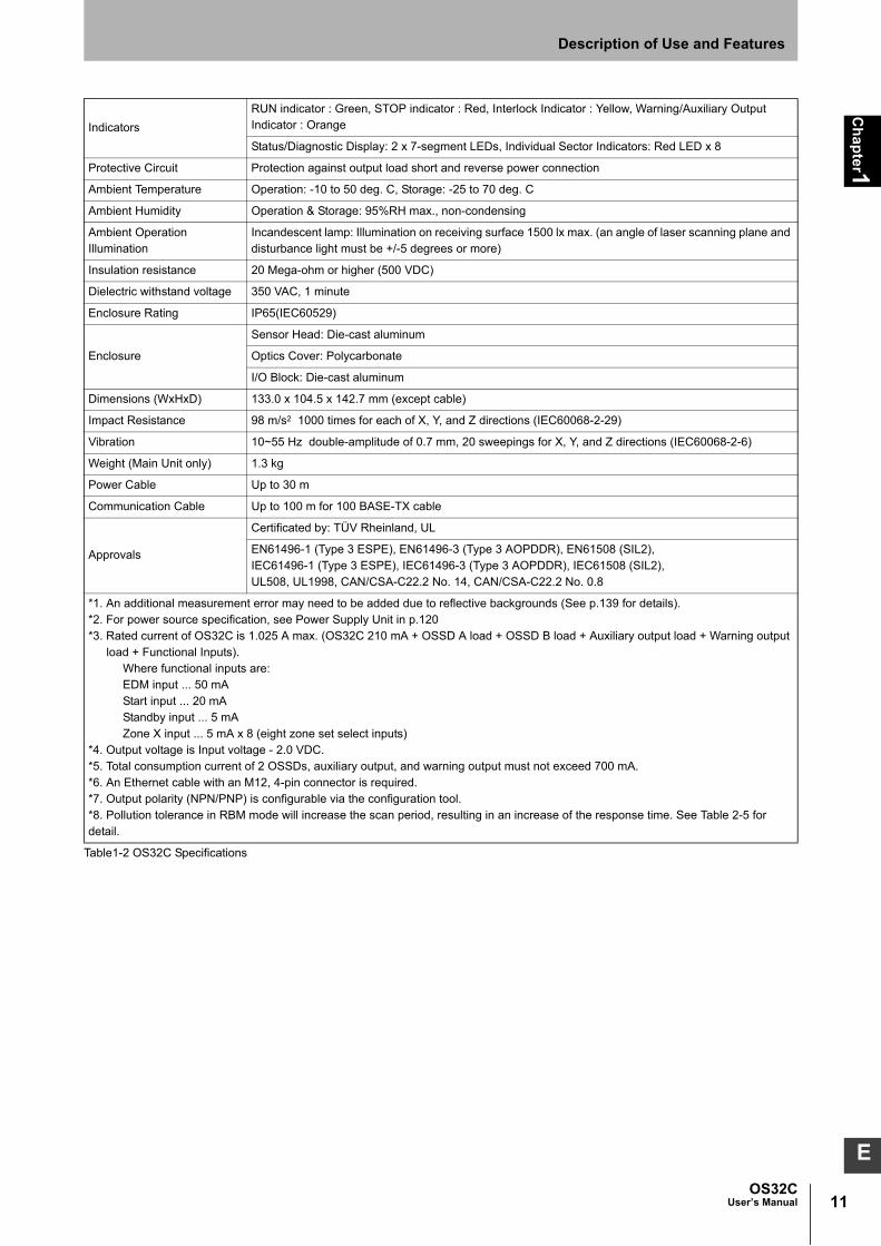
*1. An additional measurement error may need to be added due to reflective backgrounds (See p.139 for details). *2. For power source specification, see Power Supply Unit in p.120 *3. Rated current of OS32C is 1.025 A max. (OS32C 210 mA + OSSD A load + OSSD B load + Auxiliary output load + Warning output
load + Functional Inputs).Where functional inputs are:EDM input ... 50 mAStart input ... 20 mAStandby input ... 5 mAZone X input ... 5 mA x 8 (eight zone set select inputs)
*4. Output voltage is Input voltage - 2.0 VDC.*5. Total consumption current of 2 OSSDs, auxiliary output, and warning output must not exceed 700 mA.*6. An Ethernet cable with an M12, 4-pin connector is required.*7. Output polarity (NPN/PNP) is configurable via the configuration tool.*8. Pollution tolerance in RBM mode will increase the scan period, resulting in an increase of the response time. See Table 2-5 for detail.

12
Ch
ap
ter1
OS32CUser’s Manual
Description of Use and Features

Ch
apter2
13OS32C
User’s Manual
E
Chapter2 Operating States & Output Modes
Operating States 14
Operating Mode 17
Automatic Start 17
Start Interlock 17
Start/Restart Interlock 17
Power Reserve Mode 17
Parameter Configuration 18
Safety Critical Parameters 18
Non-Safety Critical Parameters 19
Safety Outputs 20
Auxiliary & Warning Outputs 20
Reference Boundary Monitoring (RBM) 22
Pollution Tolerance Mode (PTM) 23
Zone Set Selection 25
Zone Set Input Selection 25
Zone Set Switching 27

14
Ch
apter2
OS32CUser’s Manual
Operating States & Output Modes
Operating States
The following operating states exist for the OS32C system.
1. OSSD ON State
The two safety outputs are in the ON state, and the machine run (green) indicator is lit. The protected machine
is allowed to operate. The state/diagnostic display indicates a state of monitoring zone set selection and a
response time.
2. OSSD OFF State
An object exists in a safety zone and it is being detected. The two safety outputs are in the OFF state, and the
machine stop (red) indicator and the intrusion indicators in the affected region(s) are lit. The protected
machine is not allowed to operate. The status/diagnostic display shows "- -".
3. Interlock State
This state waits for a start input (See p.17 for details.). The two safety outputs are in the OFF state, the red
STOP indicator and yellow interlock indicator are lit. The protected machine is not allowed to operate. The
status/diagnostic display shows "01".
4. Lockout State
A failure is being detected and the guarded machine is being stopped. The two safety outputs are in the OFF
state, the machine stop (red) indicator is lit and yellow interlock indicator is flashing. The protected machine is
not allowed to operate. The status/diagnostic display shows the error code that caused the lockout. The
OS32C system will remain in the lockout state until the problem is corrected and a start input is applied or
power on the unit is cycled.
Indication Patterns
Table 2-1 Indication Patterns
RUN indicator(Green LED)
On When OSSD is ON
Off When OSSD is OFF
STOP indicator(Red LED)
On When OSSD is OFF
Off When OSSD is ON
Interlock Indicator(Yellow LED)
On Interlock State
Flashing Lockout State (@ 1Hz), Configuration State (@ 4Hz)
Off Other than the above
Warning output indicator(Orange LED)
On When any warning zone is intruded
Flashing When dust or contamination is detected on the scan window (@ 1 Hz)
Off Other than the above
Status/Diagnostic Display See "OS32C Status Check" on page 137.
Individual Sector Indicators(Red LED)
On When an object is in any safety or warning zone. *1, *2
Flashing When dust or contamination is detected on the scan window. *1
Off Zones are clear and window is clean.
*1 The functionality of the intrusion indicators is configurable via the configuration tool.*2 The intrusion indicators in the affected region is lit or flashing.

15OS32C
User’s Manual
Ch
apter2
Operating States & Output Modes
E
Table 2-2 OS32C Operating States and Corresponding Outputs
Status/Diagnostic DisplayWhen powered up, the OS32C will display, in the following order:
• the configured minimum object resolution for 5 seconds, as indicated in the following table:
Table 2-3 Minimum object resolution indication
• the Ethernet configuration of the OS32C for 5 seconds, as indicated in the following table:
Table 2-4 Ethernet configuration indication
This will also be displayed for 5 seconds after every time the Ethernet cable is connected to the
scanner.
• Normal operation indication: zone number and response time. See next page for details.
State RUN indicator (Green LED)
STOP indicator(Red LED)
Interlock indicator (Yellow LED)
Warning output indicator(Orange LED)
OSSDs
Power On Self Test On On On On Off
Machine Stop Off On Off Depends on configuration and object position
Off
Machine Run (Normal Operation) On Off Off Depends on configuration and object position
On
Machine Run (Dust on scan window) On Off Off Flashing (@ 1 Hz) On
Interlock Off On On Depnds on configuration and object position
Off
Standby Off On Off Off Off
Fault (Dust on scan window) Off On Flashing (@ 1Hz) Flashing (@ 1 Hz) Off
Fault (others) Off On Flashing (@ 1Hz) Off Off
Configuration Off On Flashing (@ 4Hz) Off Off
Digital Indication Minimum object resolution
L3 30mm
L4 40mm
L5 50mm
L7 70mm
Digital Indication OS32C Ethernet configuration
SP Static IP addressing
dP DHCP IP addressing

16
Ch
apter2
OS32CUser’s Manual
Operating States & Output Modes
During normal operation:
The seven-segment display indicates the current zone set and response time of the OSSDs. For
example, code 24 indicates zone set 2 with a response time of 160ms.
When the display is inverted, a decimal will be shown in the corner.
The response times longer than 400ms are represented by zero.
Left Digit
Right Digit
*1. Restart Delay parameter is configurable from 100ms to 60s with 100ms increment
See p.52 for configuring the Restart Delay parameter.
*2. See Pollution Tolerance Mode section, p.23, for more information
Table 2-5 Status/Diagnostic Display Indication
Monitoring Zone of OS32C Digital Indication
Zone Set 1 1
Zone Set 2 2
Zone Set 3 3
Zone Set 4 4
Zone Set 5 5
Zone Set 6 6
Zone Set 7 7
Zone Set 8 8
Zone Set 9 9
Zone Set 10 A
Zone Set 11 b
Zone Set 12 C
Zone Set 13 d
Zone Set 14 E
Zone Set 15 F
Zone Set 16 or higher U
ON to OFF Response time OFF to ON Response timeNumber of
ScansDigital
Indication
OSSDs out put Auxiliary and Warning Output (Configurable)
(without PTM-RBM)
(with PTM-RBM active)*2
(without PTM-RBM)
(with PTM-RBM active)*2
80 ms 94 ms 120 ms 140 ms
The OFF to ON response time = corresponding ON to OFF response time +
Restart Delay parameter*1
2 2
120 ms 140 ms 160 ms 186 ms 3 3
160 ms 186 ms 200 ms 232 ms 4 4
200 ms 232 ms 240 ms 278 ms 5 5
240 ms 278 ms 280 ms 324 ms 6 6
280 ms 324 ms 320 ms 370 ms 7 7
320 ms 370 ms 360 ms 416 ms 8 8
360 ms 416 ms 400 ms 462 ms 9 9
400 ms 462 ms 440 ms 508 ms 10 0
440 ms 508 ms 480 ms 554 ms 11 0
480 ms 554 ms 520 ms 600 ms 12 0
520 ms 600 ms 560 ms 646 ms 13 0
560 ms 646 ms 600 ms 692 ms 14 0
600 ms 692 ms 640 ms 738 ms 15 0
640 ms 738 ms 680 ms 784 ms 16 0
680 ms 784 ms 720 ms 830 ms 17 0

17OS32C
User’s Manual
Ch
apter2
Operating States & Output Modes
E
Operating Mode
Automatic StartAfter power on, OS32C automatically enters machine run (ON) state if no fault is detected during
initialization and self-tests, and if no intrusion is detected within the safety zone. An object entering the
safety zone shall turn the OSSDs OFF. Once the safety zone is clear, the sensor will automatically
enter the machine run (ON) state.
Start InterlockAfter power on, OS32C automatically enters the interlock state if no fault is detected in its system
initialization and self-tests, and if no intrusion is detected within the safety zone. To release the
interlock state, the start input must transition to open from 0 V for a minimum of 200ms and then back
to 0 V short. Once the interlock state is released and OS32C enters the machine run (ON) state, an
object entering the safety zone will turn the OSSDs OFF. Once the safety zone is clear, the sensor will
automatically enter the safety output ON state.
Start/Restart InterlockAfter power on, OS32C automatically enters the interlock state if no fault is detected in its system
initialization and self-tests, and if no intrusion is detected within the safety zone. To release the
interlock state, the start input must transition to open from 0 V for a minimum of 200ms and then back
to 0 V short. Once the OS32C has started and enters the machine run (ON) state, an object entering
the safety zone will turn the OSSDs OFF. Once the safety zone is clear, the sensor will enter the
interlock state.
Power Reserve ModePower reserve mode allows the OS32C to enter a state of reduced power consumption. This is a very
useful mode when the OS32C is installed on a battery powered AGV. This mode can be configured for
Standby Mode:
•OSSDs, AUX and WARNING outputs will be off.
•Laser is off.
•Individual Sector indicators will be deactivated.
•Diagnostic display will display “- -”, which blinks once every 2 seconds.
•Wake-up time (time it takes for the OS32C to return to normal mode) is less than 0.5s.
To use Standby mode:
•Enable Standby mode under the Power Reserve property and send this change to the scanner.
•Wire the standby input to a normally open contact, see Chapter 5 for wiring diagram.
To activate standby mode:
•The closure of a normally open contact needs to connect the standby input line to +24VDC.

18
Ch
apter2
OS32CUser’s Manual
Operating States & Output Modes
Parameter Configuration
The configuration properties consist of two sections: Safety-Critical Parameters and Non-Safety Critical
parameters.
Safety Critical Parameters External Device Monitoring (EDM)
External device monitoring is an important safety function. It verifies that the external control elements
are responding correctly.
The OS32C can operate with this feature enabled or disabled. To use external device monitoring, the
OS32C requires that a Normally Closed contact from each Control Element be fed back in for
monitoring. If these contacts do not respond as expected the OS32C will enter the lockout state and
turn off the safety outputs.
In the safety output ON state, the OS32C expects to see the external device monitoring input open. In
the safety output OFF state, the OS32C expects to see the external device monitoring input closed.
The external device monitoring inputs must change state within 300ms after a change of the OS32C's
safety outputs or lockout will occur.
Response TimeThe response time of the OS32C is proportional to the number of scans. The safety outputs will
change from on to off within a preset response time. The response time can be set from 80ms to
680ms. The number of scans may be increased when operating the OS32C in a dirty environment to
avoid nuisance trips caused by floating particulate matter.
Table 2-6 Response Time Examples
If the response time is changed, re-calculation of the safety distance is required. This may require re-configuration of the safety zones or re-installation of the OS32C. If the safety distance is not appropriate for the application, the machine may not stop before the hazardous area is reached, resulting in severe injuries.
Application Example Example of Response Time
Stationary (clean environment) 80ms
Mobile 80ms - 240ms
Stationary (Dirty environment) More than 240ms

19OS32C
User’s Manual
Ch
apter2
Operating States & Output Modes
E
Minimum Object ResolutionThe minimum object resolution (the smallest width of an object the scanner will detect), is configurable
by the user. The maximum radius of the safety zone will depend on the minimum object resolution
selected:
Table 2-7 Minimum object resolution and maximum safety zone radius
Zone Set SelectionThe OS32C is capable of monitoring up to seventy zone sets, where a zone set is defined as one
safety zone, and two warning zones. These zone sets can be controlled via programmable selectable
inputs. The installer has the ability of deciding how many and which inputs to use with the configuration
software.
For more information on Zone Set Switching, see page 27.
Zone Set Select Input CombinationsWhen multiple zones are selected, the zone set select input combination table must be configured.
These settings will be determined by the number of zones needed and available inputs.
Zone Transition DelayWhen multiple zones are used the transition time must be accounted for in the safety distance
calculation. This delay is 10 ms. This would show up as an additional component, t3, of T in the Safety
Distance calculation on page 105. The t3delay does not apply in applications without multiple zones.
Non-Safety Critical Parameters Auxiliary Output Mode
There are five possible auxiliary output settings: safety output information mode, lockout information
mode, warning zone 1 infringed mode, warning zone 2 infringed mode, and window contamination
warning mode.
Warning Output ModeThere are five possible warning output settings: safety output information mode, lockout information
mode, warning zone 1 infringed mode, warning zone 2 infringed mode, and window contamination
warning mode.
Restart Delay (Machine Stop to Machine Run Time Adjustment)This parameter is configurable when the OS32C has been configured to operate in Automatic Start
Mode.
Please see page 16 for more information.
Power Reserve Mode
See Power Reserve Mode on page 17.
Minimum object resolution (mm)Maximum safety zone radius
(3m range version) (m)Maximum safety zone radius
(4m range version) (m)
30 1.75 1.75
40 2.5 2.5
50 3.0 3.0
70 3.0 4.0

20
Ch
apter2
OS32CUser’s Manual
Operating States & Output Modes
Safety Outputs
This product is designed for use on a 24 VDC, negative ground (protective earth) electrical system only. Never connect the OS32C to a positive ground (protective earth) system. With a positive ground (protective earth) wiring scheme, certain simultaneous shorts of both safety outputs may not be detected and the guarded machine may not stop resulting in severe injury to the operator.
To use this product for a category 3 safety system, both of the two safety outputs must be used to build the safety system controls circuit. Configuring the safety control system with only one safety output may result in serious injuries due to output circuit failure.
The OS32C provides two PNP safety outputs, each capable of sourcing 250 mA @ 24 VDC. These two
outputs can be connected to the machine's primary control element, or may be used to connect to a control
device. The safety outputs will turn on when the safety zone is clear, and the guarded machine can operate.
The OS32C will turn off its safety outputs when it detects an intrusion in the safety zone, and the guarded
machine stops. In addition, the OS32C will test the safety outputs by switching the outputs off for <600μs
every ~5 min. See Fig. 2-1 below.
Fig. 2-1 OSSD Test Pulses
Auxiliary & Warning Outputs
The OS32C has a non-safety auxiliary output and a non-safety warning output, max.100mA @ 24VDC. Both
the output type (PNP/NPN) and polarity (Active ON/Active OFF) can be configured. These outputs can be
configured to operate in one of the following modes:
• Follow OSSD indication: output will turn ON when the machine stops.
• Indicate FAULT: output will turn ON when a fault has occurred.
• Warning Zone 1 infringed: output will turn ON when an intrusion is detected in warning zone 1.
• Warning Zone 2 infringed: output will turn ON when an intrusion is detected in warning zone 2.
• Window Contamination Warning: output will turn ON when contamination of the scan window reaches a
certain level.
~ 2.5minutes
OSSD A
OSSD B
~ 5 minutes
<600µs
<600µs

21OS32C
User’s Manual
Ch
apter2
Operating States & Output Modes
E
NOTE: If the unit enters a fault state, all outputs will be OFF, except in Lockout Information Mode.Table 2-8 Output Polarity
Output Mode Active ON *1 Active OFF *2
Disabled Output always OFF Output always OFF
Safety Output Information Mode Same as OSSDs (output ON when safety zone is clear)
Opposite of OSSDs (output OFF when safety zone is clear)
Lockout Information Mode Output ON when fault occurs Output OFF when fault occurs
Warning Zone 1 Information Mode Output ON when zone 1 infringed Output OFF when zone 1 infringed
Warning Zone 2 Information Mode Output ON when zone 2 infringed Output OFF when zone 2 infringed
Window Contamination Warning Mode Output ON when window contaminated Output OFF when window contamined
*1. When the polarity is Active ON, the output modes will be active when the outputs are ON.*2. When the polarity is Active OFF, the output modes will be active when the outputs are OFF.

22
Ch
apter2
OS32CUser’s Manual
Operating States & Output Modes
Reference Boundary Monitoring (RBM)
Per the international standard IEC 61496-3, area scanners used in applications where the angle of approach
exceeds +/- 30 degrees with respect to the detection plane, must use reference boundary monitoring (RBM)
of the detection zone. The tolerance zone for (RBM) must NOT exceed 100mm.
Make sure to remove any retro-reflector from the field of view of the OS32C when in RBM mode.
The OS32C has the ability to reference and monitor the presence of pre-determined areas (beams) within the
continuous solid boundary being guarded, i.e. walls, doorways, etc. A surface with openings, such as a wire
fence cannot be used for the RBM boundary. Reference boundary monitoring (RBM) is normally used in
vertical guarding installations, see Fig. 2-2.
The RBM function allows users to select certain areas on the detection zone (safety or warning) boundary and
program them to detect continuous presence. This function is intended to prevent unauthorized changes in
the physical position of the OS32C scanner.
• When RBM is enabled for the safety zone, the area (beams) that has been activated will cause a transition to
a machine stop state when a distance change is sensed.
• When RBM is enabled for a warning zone, the area (beams) that has been activated will cause a transition of
the corresponding auxiliary output when a distance change is sensed.
For complete directions on setting up reference boundary monitoring, see page 74.
The OS32C response time must not exceed 120ms, as the OS32C must detect objects moving at 1.6 meters
per second. If the detection zone is infringed or if the detection zone boundaries are changed, the scanner
shall turn off the two OSSD outputs
Fig. 2-2 Reference Boundary Monitoring
Reference boundary

23OS32C
User’s Manual
Ch
apter2
Operating States & Output Modes
E
Pollution Tolerance Mode (PTM)
This function enables a filter that allows the scanner to distinguish between more than one detected
reflections. When the scanner receives more than one detected reflection pulses during a measurement scan,
the filter will ignore the first reflected pulse which may be caused by dust accumulation on the window or air
borne dust particles within the guarded space, preventing many nuisance machine stops caused by pollution
particles.
The activation of RBM Only mode will increase the response time. This additional time must be taken into
consideration when calculating the safety guarding distance.
Refer to Table 2-5 Status/Diagnostic Display Indication for additional response time information.
To activate the RBM Only mode, the user needs to:
•Define the reference boundaries following the "Sculpting & Reference Boundary Monitoring" instruction.
NOTE: The reference boundary must be a continuous solid surface, for the installation to benefit from
RBM Only mode. A surface with openings, such as a wire fence cannot be used for the RBM
boundary.
•Select RBM Only under Pollution Tolerance Mode within Configuration Properties tab.
This function has three setting modes:
Disable: PTM is not active.
Window Only: When this mode is active, it will filter out pulse reflections in the near field, which would be
caused by dust or other contaminants on the window. This mode uses multi-pulse sampling which can ignore
small reflections emanating from the window.
RBM Only: This mode includes all features in Window Only. In addition, it will filter out pulse reflections in the
guarded space (safety zone). These pulses could be caused by airborne dust/ or other contaminants. This
mode works in conjunction with reference boundary monitoring and depends on a pre-defined reference to
provide the filtering (tolerance) function. This RBM Only mode uses multi-pulse sampling for beams
configured with reference boundaries, see Fig. 2-3. Areas consisting of beams without a reference will not
benefit from this function. See Fig. 2-4 for further explanation.

24
Ch
apter2
OS32CUser’s Manual
Operating States & Output Modes
Fig. 2-3 Full Reference Boundary
Fig. 2-4 Partial Reference Boundary
NOTE: The benefit of PTM-RBM function may vary depending on:
• The strength of the reflection caused by the contamination. This strength depends on the density and
reflectivity of the pollution source. For instance, heavy smoke or dense cloud of floating dust may still
trigger the scanner.
• The position between the OS32C and the reference boundary. The function is more effective for
pollution which is closer to the scanner and less effective when the pollution cloud extends closer to
the boundary.

25OS32C
User’s Manual
Ch
apter2
Operating States & Output Modes
E
Zone Set Selection
Zone Set Input SelectionWhen configured for multiple zones, there are a total of 8 inputs available for zone set selection for the
OS32C; it is not necessary to use them all. The minimum requirement for safe operation is 2 total
inputs. The user must also configure the total number of inputs (the number of input terminals to be
used) and active inputs (the number of inputs to be activated) needed to select a zone set. During
operation, the scanner will always monitor for that specific configuration of inputs to be active.
Once the number of inputs and active inputs is configured, the user is able to define and assign the
detection zone sets to each combination of inputs. The number of unique active combinations
available depends on the number of total inputs and the number of active inputs. Table 2-9 shows the
maximum number of zone sets possible for the various configurations. It is not necessary to have a
zone assigned to every possible combination. Unassigned combinations are assumed to be invalid.
If an invalid combination of inputs is detected, the scanner will fault out with error code 70. In this case,
check zone configuration selection, zone set select input wiring, zone set select input switching time
and zone delay configuration.
Table 2-9 Maximum number of combinations, depending on total number of inputs and total number of active inputs.
The examples below are some of the possible configurations that can be accomplished for many
applications. Here z1 and z2 are used as abbreviations of zone set select input 1 and 2.
Fig. 2-5 Two-Zone Set Application
The examples above illustrate two different wiring schemes that use two inputs with one active
required. This is used for a two-zone set application.
No. of Total Inputs (n)
8 7 6 5 4 3 2
Total No. of Active Inputs (r)
1 8 7 6 5 4 3 2
2 28 21 15 10 6 3
3 56 35 20 10 4
4 70 35 15 5
5 56 21 6
6 28 7 Maximum number of zones =
7 8
n!
r! * (n-r)!
OS32C
+24VDC
0
Input configurations
No. of active inputs = 1
1 Zone set 1
Zone set 2 1 0
z1
z2 Detection zone sets
OS32C
z1
z2
+24VDC
z1 z2

26
Ch
apter2
OS32CUser’s Manual
Operating States & Output Modes
Fig. 2-6 Three-Zone Set Application
The examples above illustrate a wiring scheme that uses three inputs with two active required. This is
used for a three-zone set application. Note that the selection of inputs is programmable; the user has
the ability to select which inputs to use. These configurations are technically the same, but different
inputs are selected as active.
Fig. 2-7 Four-Zone Set Application
The above examples illustrate two different wiring schemes that use four inputs with two active
required. The example on the left is configured for a four-zone set application. The example on the
right is configured for a six-zone set application.
Fig. 2-8 Eight-Zone Set Application
This example illustrates a wiring scheme that uses five inputs with two active required. This is used for
an eight-zone set application.
+24VDC
z1
z2
z3
1
Number of Inputs
No. of active inputs = 2
1 Zone set 1
Zone set 2 1 0
Detection zone sets z1 z2
0 1
0
1 1
z3
Zone set 3
Number of Inputs
No. of active inputs = 2
Zone set 1
Zone set 2
Detection zone sets
Zone set 3
+24VDC
z1
z2
z3
z4
z5
1
1
z1 z2
0
z3 1
0 1
0
1 1
z4 z5
OS32C OS32C
+24VDC
z1
z2
z3
1
Number of Inputs
No. of active inputs = 2
1 Zone set 1
Zone set 2 1
0 Detection zone sets z1 z2
0
0
0
1
0
z3
Zone set 3
Number of Inputs
No. of active inputs = 2
Zone set 1
Zone set 2
Detection zone sets
Zone set 3
+24VDC
z1
z2
z3
z4
z1 z2 z3 z4
z4 0 1 1
0
1
1
0
z4 1 0
1
1
1
0
1
0
0
0 1 1
0
0
1
0 Zone set 4 0 1 0
0 0 1
1
1
Zone set 4
Zone set 5
Zone set 6
OS32C OS32C
Number of Inputs
No. of active inputs = 2* Multiple inputs can be assigned to the same zone set
Zone set 1
Zone set 2
Detection zone sets
Zone set 3
+24VDC z1
z2
z3
z4
z1 z2 z3 z4 1
0
1
1
1
0
1
0
0
1 0 0
0 0
1
0 0 1 1
0 1 0
0
1
Zone set 4
Zone set 5
Zone set 6 z5
0 0
0
1 0
0
0 1 0
0 0 1
0
1 0 0 1
0 0 0
0
1
1
0 1
1
z5
Zone set 7
Zone set 8
Zone set 6 *
Invalid
OS32C

27OS32C
User’s Manual
Ch
apter2
Operating States & Output Modes
E
Zone Set Switching Introduction to zone set switching
As an example, examine a system configured to use 4 inputs with 2 of them active according to the
following table:
The following figure represents a transition from ZONE 1 to ZONE 2:
Fig. 2-9 Zone Switching example
If the external zone switching device momentarily exceeds the configured number of active zone set select inputs during the zone switch, an additional Zone Delay may be incurred in the event that wiring of a zone set select input fails. The external zone switching device must properly sequence so the configured number of active inputs is not exceeded in order to guarantee that failed zone set select input wiring will be detected within the normal Zone Switching Time described below.
Let's consider an example Zone set A to Zone set B switching, where A represents any origin zone set
number and B represents any destination zone set number.
When switching zone sets, there are three installation dependent parameters:
1) Zone Set Switching Timing - When switching from Zone set A, there is a point in time when
protection of that zone set is no longer required, this point will be defined as tEndZoneA. When
transitioning to Zone set B, there is a point in time when the OSSDs must turn OFF if an object is
present in Zone set B, this point will be defined as tDangerZoneB. In order to ensure, tDangerZoneB is
met, monitoring of Zone set B must start at least one response time (Tresponse) prior to tDangerZoneB.
The time at which monitoring of Zone set B must start will be defined as tStartZoneB, where
tStartZoneB = tDangerZoneB - Tresponse
Zone Set Select Inputs
Z1 Z2 Z3 Z4
Zone SetsZone set 1 LOW HIGH HIGH LOW
Zone set 2 HIGH LOW LOW HIGH
Z1
Z2
Z3
Z4
MonitoredZone Zone set 1 Zone set 2
Zone set select input switching time
Zone set switching time
Zne Set Select Inputs

28
Ch
apter2
OS32CUser’s Manual
Operating States & Output Modes
2) Zone Set Select Input Switch Timing - The worst case time it can take for switching zone set
select inputs. This time starts on the transition on the first input change and ends to the transition
on the last input change, this will be defined as Tswitches.
3) Zone Set Select Input Switch Tolerance - It is required that the zone set select input switching
circuitry begin switching the zone set inputs at a precise time relative to when the zone set
transition is desired to occur. The tolerance of timing when input state is actually switched,
generated by input switching circuitry, will be defined using +/- Ttol.
The simplest monitoring zone set switching timing in an installation is tEndZoneA < tStartZoneB. In this case,
the interval between tEndZoneA and tEndZoneA does not require any monitoring, thus switching from zone
set A to zone set B is straightforward. But when tEndZoneA = tStartZoneB or tEndZoneA > tStartZoneB, both zone set
A and zone set B may need to be monitored simultaneously. In such case, refer to How to Guarantee
Protection of Original Zone Set.
Fig. 2-10 Switch from Zone set A to Zone set B.
The Zone Set Input Switch Timing must be configured to consider delay time of input switching circuitry
and ensure proper monitoring and safety. The configuration parameter Zone Set Switching Delay
(Tdelay) needs a value larger than Tswitches in increments of 20 ms (Tsample). In the following example,
Tdelay is configured to 80ms or more.
Fig. 2-11 Zone Delay configuration.
If an insufficient Zone Delay is used for the actual worst case zone set select input switching time of the installation, an unintended zone set may be temporarily enabled, resulting in temporarily monitoring the wrong zone.
Also, it must be ensured that after a zone switch there is a minimum "hold time" before the next zone
switch can take place. That time is 2 * Tsample.
Zone set B Zone set A Zone set A
ORZone set B
tEndZoneA tDangerZoneB
time
Monitoring zone set
tStartZoneB
T response
Tswitches
T delay
20 ms 20 ms 20 ms 20 ms
round up

29OS32C
User’s Manual
Ch
apter2
Operating States & Output Modes
E
The Zone Input Switch Tolerance(Ttol) is the tolerance on when the zone switching circuitry is actually
able to start the switching of the inputs.
Besides Ttol and Tdelay, there is an additional delay of up to Tsample before the change on the zone set
select inputs is recognized.
Therefore, assuming switching of the inputs starts at tstart, the system is guaranteed to switch zones
between tmin = tstart + Tdelay - Ttol and tmax = tstart + Tdelay + Ttol + Tsample.
Fig. 2-12 Zone set select input switching and zone set switch.
How To Configure Input Switch Circuitry TimingRelative to tstart, the longest time it will take to begin monitoring Zone set B is tmax. When you take into
account the scanner's response time required to actually detect an object present in Zone set B, the
longest time to turning off the OSSDs relative to tstart can be shown as:
tmaxToOff = tmax + Tresponse
The critical timing guarantee to be met when changing zone sets is tDangerZoneB. The input switching
circuitry should begin switching the zone set select inputs prior to tDangerZoneB to ensure Zone B is
activated early enough to detect an object previously present in the zone set. The amount of time prior
to tDangerZoneB to start switching can be derived from tmaxToOff by equating it to tDangerZoneB.
tstart = tDangerZoneB - (Tresponse + Tdelay + Ttol + Tsample)
This means the switching circuitry must be configured to begin switching the inputs TmaxReaction before
tDangerZoneB to ensure safe monitoring of Zone set B, where
TmaxReaction = Tresponse + Tdelay + Ttol + Tsample
If tstart (switching start time) is configured without consideration of TmaxReaction (total maximum reaction time), object detection within the new safety zone after switching and turning OFF of the safety outputs may be delayed.
T delay Tsample
tstart
Startswitching
t min =tstart + Tdelay - TtolZone set switches
(earliest)
tmax =tstart + Tdelay + Ttol + Tsample
Zone set switches(latest)
Ttol
T delayTtol
Monitoring zone set
time
Zone set BZone set AZone set A
ORZone set B
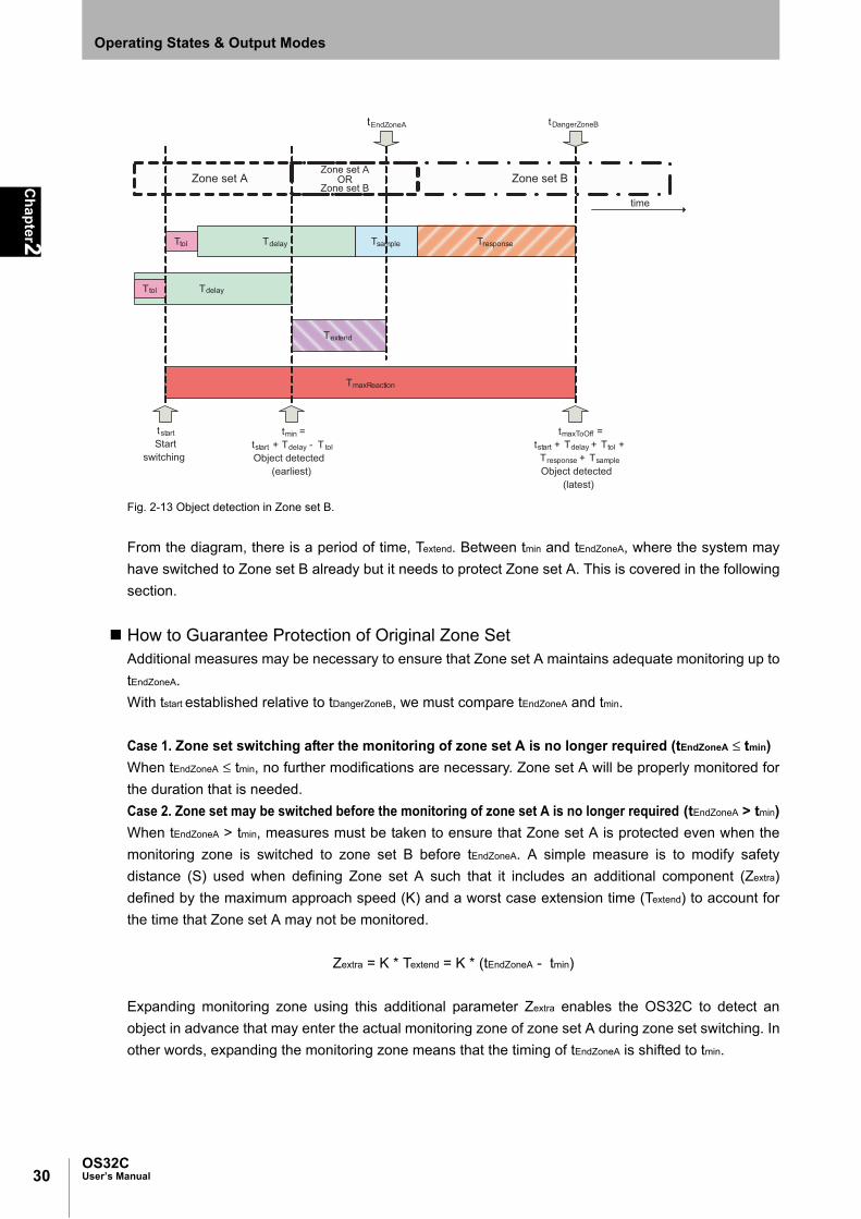
30
Ch
apter2
OS32CUser’s Manual
Operating States & Output Modes
Fig. 2-13 Object detection in Zone set B.
From the diagram, there is a period of time, Textend. Between tmin and tEndZoneA, where the system may
have switched to Zone set B already but it needs to protect Zone set A. This is covered in the following
section.
How to Guarantee Protection of Original Zone SetAdditional measures may be necessary to ensure that Zone set A maintains adequate monitoring up to
tEndZoneA.
With tstart established relative to tDangerZoneB, we must compare tEndZoneA and tmin.
Case 1. Zone set switching after the monitoring of zone set A is no longer required (tEndZoneA ≤ tmin)
When tEndZoneA ≤ tmin, no further modifications are necessary. Zone set A will be properly monitored for
the duration that is needed.
Case 2. Zone set may be switched before the monitoring of zone set A is no longer required (tEndZoneA > tmin)
When tEndZoneA > tmin, measures must be taken to ensure that Zone set A is protected even when the
monitoring zone is switched to zone set B before tEndZoneA. A simple measure is to modify safety
distance (S) used when defining Zone set A such that it includes an additional component (Zextra)
defined by the maximum approach speed (K) and a worst case extension time (Textend) to account for
the time that Zone set A may not be monitored.
Zextra = K * Textend = K * (tEndZoneA - tmin)
Expanding monitoring zone using this additional parameter Zextra enables the OS32C to detect an
object in advance that may enter the actual monitoring zone of zone set A during zone set switching. In
other words, expanding the monitoring zone means that the timing of tEndZoneA is shifted to tmin.
tstartStart
switching
tmin =tstart + Tdelay - T tolObject detected
(earliest)
tmaxToOff =tstart + Tdelay + Ttol +
Tresponse + TsampleObject detected
(latest)
T delay
Zone set BZone set A
Tsample
Zone set A OR
Zone set B time
Ttol
T delayTtol
T response
tDangerZoneBtEndZoneA
T extend
TmaxReaction

31OS32C
User’s Manual
Ch
apter2
Operating States & Output Modes
E
Fig. 2-14 Zone A extension.
The extension of the safety distance around the entire protection zone will guarantee the safe
operation of the scanner. However, most installations may benefit from using the smallest possible
monitoring zone perimeter to maximize usable work space. For other measures, refer to Additional
Zone Set Switching Strategies on page 147.
Zone set A ExtensionZone set A
Zone set B
Zextra
S
Danger Areaof Zone set A
OS32C

32
Ch
apter2
OS32CUser’s Manual
Operating States & Output Modes

Ch
apter3
33OS32C
User’s Manual
E
Chapter3 Basic Operation of ConfigurationSoftware
Getting Started 35
Installing Configuration Software 35
How to Start 36
Description of Screen 37
Menu 37Tool Bars 39Information Bar 40Offline Mode 40
Connection to the OS32C 41
Connecting the PC and the OS32C 41Forced DHCP mode 42Changing the IP address of the PC (Windows 2000) 42Changing the IP address of the PC (Windows XP) 42Changing the IP address of the PC (Windows Vista) 44Changing the IP address of the PC (Windows 7) 44
Logging on to the OS32C 45
Detecting the OS32C on the network 45Logging On 46Logging OFF 46Changing Password 46Forgot the Password? 47
Changing Ethernet Configuration of OS32C 48
Receiving OS32C Configuration Information 49
Configuring New OS32C Property and Monitoring Zone 49
Default Configuration Settings 49Creating a New Configuration 50
Import & Export Zone Coordinate Data 55
File Format 55Importing Zone Coordinate Data 58Exporting Zone Coordinate Data 60
Zone Set Selection and Configuration 62
Add a Zone 62Copy and Paste Zones 63Delete a Zone 65
Zone Set Input Selection 66
Editing Properties 67
Editing Monitor Zones 71
Sculpting & Reference Boundary Monitoring 74
Monitor Mode 79
Record System Monitoring 80
Playback System Monitoring 82
Read Fault Log 83
34
Ch
apter3
OS32CUser’s Manual
Basic Operation of Configuration Software
Window Calibration 84
Changing Options of Configuration Software 86
Caution on Safety Zone Configuration 87
Reset to Default Configuration 88
35OS32C
User’s Manual
Ch
apter3
Basic Operation of Configuration Software
E
Getting Started
The configuration and installation of an OS32C is a simple process. Here are the basic steps needed to get
started. Refer to the appropriate section of Chapter 3 for more information on any of these steps.
• Install the configuration tool
• Connect the OS32C to the same network as the computer
• Start the configuration tool
• Discover scanners on the network
• Log on to the OS32C
- Select Access Level
- Enter password
• Create new configuration
- Safety-critical parameters (EDM, response time, operating mode, zone sets, minimum object resolution
etc.)
- Non-safety-critical parameters (auxiliary output, warning output, power consumption mode, etc)
- Zone configuration
• Send configuration to the OS32C
Installing Configuration Software
Installation of the configuration software for the OS32C requires the following:
• Pentium 4 class 1.5GHz CPU or equivalent
• Windows 2000, Windows XP, Windows Vista, or Windows 7
• 512MB of RAM
• 10MB of available hard disk space
• Monitor with resolution of 1024 x 768 pixels or better.
Install the software based on the following steps:
1. Terminate all applications running.
2. Insert CD-ROM of the configuration software to your CD drive.
3. Double-click the CD-ROM icon in My Computer to run Setup.exe.
4. Follow instructions of the installer program.
5. A program icon appears where you specified during installation.
To install the configuration software on Windows 2000, Windows XP Professional, Windows Vista, or Windows 7, a user
account of supervisory access level (Administrators) is required.

36
Ch
apter3
OS32CUser’s Manual
Basic Operation of Configuration Software
How to Start
Select Start, All Programs, OS32C Configuration Tool, and OS32C Configuration Tool (if you have not
changed the program folder name).
Fig. 3-1 OS32C Configuration Tool

37OS32C
User’s Manual
Ch
apter3
Basic Operation of Configuration Software
E
Description of Screen
The configuration software consists of the following:
MenuFile
Table 3-1
Edit
Table 3-2
View
Table 3-3
New Used to create new configuration of OS32C
Open Opens a configuration information file saved on PC
SaveSaves created configuration information on PC, or overwrites the existing configuration file if it was edited
Save As Saves created configuration information on PC
Print Configuration Prints OS32C configuration information
Print Screen Snapshot Prints the zone information screen only with current window zoom
Exit Terminates the configuration software
Undo Undo last action
Redo Redo last action
Delete Selected Points Delete selected point(s) (Applies to polygon shaped zone)
Select a Group of Points Select a group of points (Applies to polygon shaped zone)
Copy Zone Copy the zone currently selected (in the Foreground pull-down menu).
Paste ZonePaste a copied zone to the zone currently selected (in the Foreground pull-down menu).
Convert Shape to
Circular Segment Convert zone being edited to a circular segment
Polygon Convert zone being edited to a polygon
Rectangle 180° Convert zone being edited to a rectangle
Import Zone Data Import zone shape data from a textfile.
Export Zone Data Export zone shape data to a textfile.
Tool BarMain Tool Bar Shows or hides the Main Tool Bar
Edit Tool Bar Shows or hides the Edit Tool Bar
Status Bar Shows or hides the status bar
View All Shows the zone information screen with minimum zoom
View Center Shows the zone information screen with OS32C in the center
Zoom In Magnifies the zone information screen
Zoom Out Minimizes the zone information screen
Zoom Window Magnifies a specified range of the zone information screen
Show/Hide Warning Zone 1 Shows or hides warning zone 1 in the zone information screen
Show/Hide Warning Zone 2 Shows or hides warning zone 2 in the zone information screen
Polar Coordinate View the monitoring zone using the polar coordinate system
Cartesian Coordinate View the monitoring zone using the cartesian coordinate system
Show/Hide Grid Shows or hides grid
Show/Hide Scale Shows or hides the scaling
Change Measurement Unit Change unit of measure. (mm, cm, or inches)
Flip view horizontally Changes the PC screen view in a horizontal direction
Flip view vertically Changes the PC screen view in a vertical direction

38
Ch
apter3
OS32CUser’s Manual
Basic Operation of Configuration Software
Configuration
Table 3-4
Reference Boundary Monitoring
Table 3-5
Utilities
Table 3-6
Edit Properties Shows the configuration properties screen
Edit Zone Switches to the monitoring zone configuration mode
Add Zone Set Add a new zone to the configuration
Sculpting Enable/Disable sculpting mode
Receive from Sensor Receives current configuration information from the OS32C
Send to Sensor/Enter CFG Mode
All Changes Sends only the changed item(s) (safety and non-safety) to OS32C for registration (available at Supervisor access level only)
Entire Configuration
Sends all setup items (safety and non-safety) to OS32C for registration (available at Supervisor access level only)
All Changes (Non-Safety Only)
Sends only the changed item(s) of non-safety parameter(s) to OS32C for registration. The user can select this option at Supervisor and Maintenance access levels.
Entire Configuration (Non-Safety Only)
Sends all setup items of non-safety parameter(s) to OS32C for registration. The user can select this option at Supervisor and Maintenance access levels.
Register Changes/Exit CFG Mode Register the changed item(s) previously sent to OS32C and exit configuration mode.
Discard Changes/Exit CFG Mode Discard all changed item(s) previously sent to OS32C and/or exit configuration mode.
Configuration checksum View checksum for the current configuration
Reset to Default Configuration Reset the scanner back to manufacture default configuration (available at Supervisor access level only)
Disable Setting Disable reference boundary monitoring for the selected zone.
Set Point as Reference Boundary Set selected point(s) as reference boundary monitoring points.
Set Point as Non-reference Boundary
Un-set the selected point(s) as reference boundary monitoring point(s).
Set All as Reference Boundary Set all points in the zone for reference boundary monitoring.
Set All as Non-reference Boundary Set none of the points in the zone for reference boundary monitoring.
Set Zone Tolerance Set the reference boundary monitoring tolerance for a zone.
Save Reference Boundary Setting Apply reference boundary monitoring settings to the zone.
Discover Sensors Find sensors on the network
Log On Used to log on to the OS32C
Log Off Used to log off from the OS32C
Change Sensor Name Change the name of the OS32C
Sensor Ethernet Configuration Change the IP address of the OS32C
Change Password Used to change the password
Read Encrypted Password Shows the encrypted password in case of lost password
Read Fault LogSensor Displays the fault log of the sensor block
I/O Block Display the fault log of the I/O block
System Information Display the system and ethernet configuration of the OS32C
Window Calibration Used after the window is replaced
System MonitoringShows current OS32C scanning zone information on the zone information screen in real-time
Record System Monitoring Record OS32C scanning zone information
Playback System Monitoring Playback previously recorded OS32C scanning zone information
Options Change configuration software options

39OS32C
User’s Manual
Ch
apter3
Basic Operation of Configuration Software
E
Tool Bars
Fig. 3-2
Table 3-7
Fig. 3-3
Table 3-8
(1) Create a new configuration Used to create new configuration of OS32C
(2) Open configuration from file Opens a configuration information file saved on PC
(3) Save configuration to file Saves created configuration information on PC
(4) Print configuration Prints OS32C configuration information
(5) System Monitoring Shows current scanning zone information on the zone information screen in real-time
(6) Sculpting Enable/disable sculpting mode
(7) Record system monitoring Record OS32C scanning zone information
(8) Playback system monitoring Playback previously recorded OS32C scanning zone information
(1) Change measurement unit Change unit of measure (mm, cm, or inches)
(2) Zoom in Magnifies the zone information screen
(3) Zoom out Minimizes the zone information screen
(4) Zoom window Magnifies a specific area of the zone information screen
(5) View center Shows the zone information screen with the OS32C in the center
(6) View all Shows the zone information screen with minimum zoom
(7) Toggle view panningEnables/Disables view panning (Allow a user to click on the displayed zone and move their mouse to adjust their view of the zone).
(8) Edit zone Enables/Disables the editing of zones
(9) Convert shape to Convert zone being edited to a circular segment, polygon, or rectangle
(10) Undo Undo last action
(11) Redo Redo last action
(12) Add Zone Set Add a new zone to the configuration
(13) Copy zone Copy the zone currently selected (in the foreground).
(14) Paste zone Paste a copied zone to the zone currently selected (in the foreground).
(15) Flip view horizontally Changes the PC screen view in a horizontal direction
(16) Flip view vertically Changes the PC screen view in a vertical direction
(17) Reset Flip view Reset the PC screen view to the default orientation
(18) Toggle rotation tool bar Show/Hide the rotation tool bar
(1) (2) (3) (4) (5) (6) (7) (8)
(1) (2) (3) (4) (5) (6) (7) (8) (9) (10) (11) (12) (13) (14) (15) (16) (17) (18)
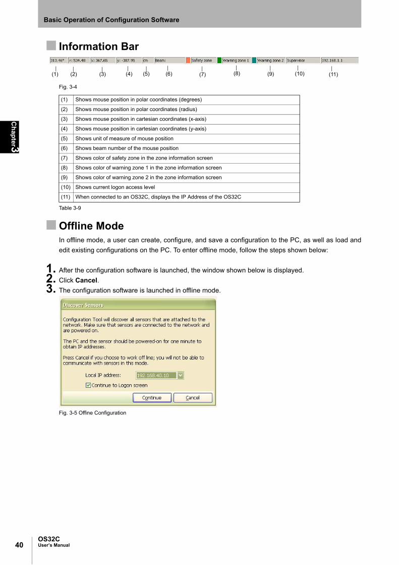
40
Ch
apter3
OS32CUser’s Manual
Basic Operation of Configuration Software
Information Bar
Fig. 3-4
Table 3-9
Offline ModeIn offline mode, a user can create, configure, and save a configuration to the PC, as well as load and
edit existing configurations on the PC. To enter offline mode, follow the steps shown below:
1. After the configuration software is launched, the window shown below is displayed.
2. Click Cancel.
3. The configuration software is launched in offline mode.
Fig. 3-5 Offine Configuration
(1) Shows mouse position in polar coordinates (degrees)
(2) Shows mouse position in polar coordinates (radius)
(3) Shows mouse position in cartesian coordinates (x-axis)
(4) Shows mouse position in cartesian coordinates (y-axis)
(5) Shows unit of measure of mouse position
(6) Shows beam number of the mouse position
(7) Shows color of safety zone in the zone information screen
(8) Shows color of warning zone 1 in the zone information screen
(9) Shows color of warning zone 2 in the zone information screen
(10) Shows current logon access level
(11) When connected to an OS32C, displays the IP Address of the OS32C
(1) (2) (3) (4) (5) (6) (8) (7) (9) (10) (11)

41OS32C
User’s Manual
Ch
apter3
Basic Operation of Configuration Software
E
Connection to the OS32C
This section describes how to connect a PC with the configuration software and the OS32C.
The configuration software is connected to the OS32C via Ethernet. An Ethernet cable with an M12, 4-pin
connector is required.
See page 117 for more details.
The default Ethernet configuration of the OS32C is DHCP mode (configuration to automatically obtain an IP
address).
When connecting a PC to the OS32C, different types of connections are available depending on the user's
environment. See the following examples according to your connection environment.
Connecting the PC and the OS32C1. Physically connect the OS32C to the PC.
•For a direct connection, use an Ethernet cable to connect the OS32C directly to the Ethernet port
of the PC.
-- or --
•Use an Ethernet cable to connect the OS32C to the local area network of the PC.
On a network that limits the connection by MAC address authentication, etc., modify the settings to allow the OS32C
to connect to the network.
2. Configure the Ethernet settings of the PC and the OS32C so that they can communicate with each
other. There are two ways to do this:
•Configure both the PC and the OS32C to DHCP mode.
Set both the PC and the scanner to DHCP mode (both devices are set to obtain an IP address
automatically). If no DHCP server is present on the network, it will take approximately 40
seconds to establish the connection after connecting the PC to the OS32C. While the
connection is being established, the Local Area Connection icon on the system tray will look
like this:
Fig. 3-6 Connecting Icon
The configuration tool will not be able to connect to the OS32C while this icon is displayed.
A Limited Connection icon will be displayed after the connection icon on the system tray
disappears. The configuration tool will now be able to connect to the OS32C.
Fig. 3-7 Limited Connectivity
-- or --
•Configure both the PC and the OS32C to different fixed IP addresses on the same network.
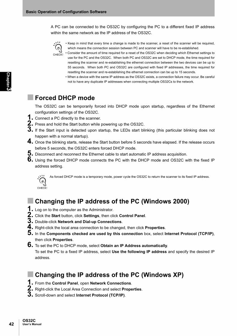
42
Ch
apter3
OS32CUser’s Manual
Basic Operation of Configuration Software
A PC can be connected to the OS32C by configuring the PC to a different fixed IP address
within the same network as the IP address of the OS32C.
• Keep in mind that every time a change is made to the scanner, a reset of the scanner will be required,
which means the connection session between PC and scanner will have to be re-established.
• Consider the amount of time required for a reset of the OS32C when deciding which Ethernet settings to
use for the PC and the OS32C. When both PC and OS32C are set to DHCP mode, the time required for
resetting the scanner and re-establishing the ethernet connection between the two devices can be up to
55 seconds. When both PC and OS32C are configured with fixed IP addresses, the time required for
resetting the scanner and re-establishing the ethernet connection can be up to 15 seconds.
• When a device with the same IP address as the OS32C exists, a connection failure may occur. Be careful
not to have any duplicate IP addresses when connecting multiple OS32Cs to the network.
Forced DHCP modeThe OS32C can be temporarily forced into DHCP mode upon startup, regardless of the Ethernet
configuration settings of the OS32C.
1. Connect a PC directly to the scanner.
2. Press and hold the Start button while powering up the OS32C.
3. If the Start input is detected upon startup, the LEDs start blinking (this particular blinking does not
happen with a normal startup).
4. Once the blinking starts, release the Start button before 5 seconds have elapsed. If the release occurs
before 5 seconds, the OS32C enters forced DHCP mode.
5. Disconnect and reconnect the Ethernet cable to start automatic IP address acquisition.
6. Using the forced DHCP mode connects the PC with the DHCP mode and OS32C with the fixed IP
address setting.
As forced DHCP mode is a temporary mode, power cycle the OS32C to return the scanner to its fixed IP address.
Changing the IP address of the PC (Windows 2000)1. Log on to the computer as the Administrator.
2. Click the Start button, click Settings, then click Control Panel.
3. Double-click Network and Dial-up Connections.
4. Right-click the local area connection to be changed, then click Properties.
5. In the Components checked are used by this connection box, select Internet Protocol (TCP/IP),
then click Properties.
6. To set the PC to DHCP mode, select Obtain an IP Address automatically.
To set the PC to a fixed IP address, select Use the following IP address and specify the desired IP
address.
Changing the IP address of the PC (Windows XP)1. From the Control Panel, open Network Connections.
2. Right-click the Local Area Connection and select Properties.
3. Scroll-down and select Internet Protocol (TCP/IP).

43OS32C
User’s Manual
Ch
apter3
Basic Operation of Configuration Software
E
4. With Internet Protocol (TCP/IP) highlighted, click Properties.
Fig. 3-8 Local Area Connection Properties
5. To set the PC to DHCP mode, select Obtain an IP Address automatically.
To set the PC to a fixed IP address, select Use the following IP address and specify the desired IP
address.
Fig. 3-9 TCP/IP Properties

44
Ch
apter3
OS32CUser’s Manual
Basic Operation of Configuration Software
6. When selecting Obtain DNS server address automatically, an alternate configuration can be set. To
set a fixed IP address for the alternate configuration, select Use the following IP address from the
Alternate Configuration tab. Set an IP address correctly according to the network environment. If you
do not set the IP address, select Automatic private IP address.
Fig. 3-10 Alternate Configuration
Changing the IP address of the PC (Windows Vista)1. Click the Start button, then click Control Panel.
2. Click Network and Internet.
3. Click Network and Sharing Center.
4. Click Manage network connections.
5. Right-click on the connection to be changed, and select Properties. If prompted for an administrator
password, enter the password and confirm.
6. Select the Networking tab.
7. Select Internet Protocol Version 4 (TCP/IPv4) and then click Properties.
8. To set the PC to DHCP mode, select Obtain an IP Address automatically.
To set the PC to a fixed IP address, select Use the following IP address and specify the desired IP
address.
Changing the IP address of the PC (Windows 7)1. Click the Start button, then click Control Panel.
2. In the search box, type adapter.
3. Under Network and Sharing Center, click View network connections.
4. Right-click on the connection to be changed, then select Properties. If prompted for an administrator
password, enter the password and confirm.
5. Select the Networking tab.
6. Select Internet Protocol Version 4 (TCP/IPv4) then click Properties.
7. To set the PC to DHCP mode, select Obtain an IP Address automatically.
To set the PC to a fixed IP address, select Use the following IP address and specify the desired IP
address.

45OS32C
User’s Manual
Ch
apter3
Basic Operation of Configuration Software
E
Logging on to the OS32C
There are 3 types of access levels:
• Operator Access Level (Operator)
To log on to the OS32C with this access level, a password is not required. This access level cannot make
changes to OS32C configurations. Only verification and monitoring of existing configuration is available.
• Maintenance Access Level (Maintenance)
To log on to the OS32C with this access level, a password is required. This access level allows a user to
modify the non-safety parameters only. This includes the warning zone shapes as well as the non-safety
critical parameters on page 52.
• Supervisory Access Level (Supervisor)
To log on to the OS32C with this access level, a password is required. This access level allows a user to
check, change and monitor OS32C configuration information.
NOTE: When planning to remotely log on to an OS32C that is located on a different subnet from the subnet of
the PC the following steps are needed during initial setup:
-The OS32C must have a dedicated password, the default password must be changed.
-The OS32C should be configured with a specific static IP address.
This will allow remote logon with full read/write access to the OS32C configuration.
Detecting the OS32C on the networkTo connect to the OS32C using the configuration software, the user needs to find the IP address of the
OS32C on the network. Select Discover Sensors from the Utilities menu.
Since the configuration software is connected to the OS32C via Ethernet, Windows Security Alert is
displayed when Windows firewall is activated. Select Unblock. The alert will not be displayed once it is
unblocked.
Fig. 3-11 Windows Security Alert

46
Ch
apter3
OS32CUser’s Manual
Basic Operation of Configuration Software
Logging On1. From Utilities menu, select Log On.
2. The Log On screen is displayed. Select an IP address of the OS32C to be connected.
Fig. 3-12 Logging On
3. Select User access level and enter a password. The initial password for the maintenance access level
is "mainusr". The initial password for the supervisor access level is "supeusr".
4. Click Continue.
5. When connected, the IP address and User access level of the OS32C are displayed.
Fig. 3-13 Logged On to Sensor
Logging OFFFrom the Utilities menu, select Log OFF and click OK.
Changing PasswordTo limit access by an unauthorized user, the password may be changed. The user needs to log on to
the OS32C with the desired access level to change the password. At Supervisor access level,
passwords for Supervisor and Maintenance access levels can be changed. At Maintenance access
level, only password of this access level can be changed. No password change is permitted at
Operator access level. The following steps describe this process:
1. Log on to OS32C with the desired access level.
2. From the Utilities menu, select Change Password.
3. Enter the current password.
4. From Change Password, select an access level you want to change.
5. Enter the new password.
6. Enter the new password again for confirmation.
7. Click Change Password.

47OS32C
User’s Manual
Ch
apter3
Basic Operation of Configuration Software
E
8. A confirmation message is displayed. Click Yes to change the password.
Fig. 3-14 Change User Password
The password must contain at least 4 but no more than 7 alphanumeric characters. The password is case-sensitive.
Forgot the Password?If the password has been lost/forgotten, follow the steps shown below to acquire the password. This
procedure must be executed under the operator access level.
1. Log on with the Operator access level.
2. From the Utilities menu, select Read Encrypted Password.
3. Select Maintenance or Supervisor and click Read Password.
4. The encrypted password is displayed on the screen.
5. Contact OMRON STI's sales representative with this character string.

48
Ch
apter3
OS32CUser’s Manual
Basic Operation of Configuration Software
Changing Ethernet Configuration of OS32C
1. From the Utilities menu, select Ethernet Configuration.
2. To configure the OS32C to DHCP mode, select Obtain an IP Address automatically. To configure the
OS32C to a fixed IP address, select Use the following IP address to specify an IP address. Set an IP
address correctly according to the network environment.
Fig. 3-15 Ethernet IP Address
3. Click Write to Sensor.
4. Confirm the change in Ethernet configuration. Click NO to abort the change.
5. The following window is displayed. Read the message and decide if you want to continue to use the
current IP address or start using the new address now.
Fig. 3-16 Ethernet Configuration
49OS32C
User’s Manual
Ch
apter3
Basic Operation of Configuration Software
E
Receiving OS32C Configuration Information
The configuration software receives and displays current configuration information immediately upon
connection to the OS32C. Configuration information can be received manually as well. From Configuration
menu, click Receive from Sensor. Configuration information is retrieved from the sensor.
Configuring New OS32C Property and Monitoring Zone
To use the protective function of OS32C, a safety zone must be properly defined and configured.
If the response time is changed, re-calculation of the safety distance is required. This may require re-configuration of the safety zones or re-installation of the OS32C. If the safety distance is not appropriate for the application, the machine may not stop before the hazardous area is reached, resulting in severe injuries.
This section describes how to configure a new monitoring zone or change the operating properties of the
OS32C using the configuration software.
Default Configuration Settings
Safety Critical Parameters
External Device Monitoring Disable
Response time (ms) 80
Monitoring zone Zone 1
Zone delay (ms) 60
Operating mode Automatic Start
Minimum Object Resolution (mm) 70
Pollution tolerance mode Window Only
Non-Safety Critical Parameters
Restart delay (ms) 400
Auxiliary output mode Follow OSSD
Auxiliary output type PNP
Auxiliary output polarity Active ON
Warning output mode Follow OSSD
Warning output type PNP
Warning output polarity Active ON
Power reserve mode Disable
Seven-segment display Enable - Non-Inverted
ISI option Enable
ISI mode Follow safety zone
Warning zone selection by EIP (OS32C-xxx-DM) Disable
Safety Zone
Shape Circular segment
Radius (cm) 100
Scan angle (degrees) 270
Warning zone 1
Shape Circular segment

50
Ch
apter3
OS32CUser’s Manual
Basic Operation of Configuration Software
Table 3-10 Default Settings
Creating a New ConfigurationTo change the configuration of the OS32C, a user must log on to the OS32C with the supervisory
access level.
1. From File menu, select New.
2. Enter a description for the configuration (up to 127 characters) and select applicable sensor model.
Fig. 3-17 Configuration Description
Radius (cm) 200
Scan angle (degrees) 270
Warning zone 2
Shape Circular segment
Radius (cm) 300
Scan angle (degrees) 270

51OS32C
User’s Manual
Ch
apter3
Basic Operation of Configuration Software
E
3. New configuration screen is displayed.
• Safety Critical Parameters
1. External Device Monitoring (EDM) : When enabled the OS32C can monitor the N.C. contacts of the
external control relays. These relays are controlled by the
OSSD safety outputs.
2. Response Time : Configures a time period for OS32C safety output from ON to
OFF. The available range is from 80ms to 680ms in increments
of 40ms.
3. Monitoring Zone : To configure only one zone set, select Single zone. To
configure more than one zone, select Multiple zone.
4. Zone Delay : Select the desired Zone Delay. The available range is 20ms to
320ms in increments of 20ms.
5. Operating Mode : A user can select from Automatic Start, Start Interlock, or
Start/Restart Interlock.
6. Minimum Object Resolution : Select the minimum object size to be detected by the scanner.
Select from 3.0cm, 4.0cm, 5.0cm, and 7.0cm.
Fig. 3-18 New Configuration Parameters for OS32C-xxx
and OS32C-xxx-4M
Fig.3-18b New Configuration Parameters for OS32C-xxx-
DM and OS32C-xxx-DM-4M
52
Ch
apter3
OS32CUser’s Manual
Basic Operation of Configuration Software
The minimum object resolution is displayed on the seven
segment display for 5 seconds on power up. Refer to "Status/
Diagnostic Display" in Chapter 2 for more detail.
7. Pollution Tolerance Mode (PTM) : A user can select from Disable, Window Only, and RBM Only.
• Non-Safety-Critical Parameters
1. Restart Delay : Select the desired OFF-to-ON delay when wiring the OS32C inAutomatic Start. Available range is 100ms to 60s, in incrementsof 100ms.
2. Auxiliary Output Mode : Select either Disable, Follow OSSD, Indicate FAULT,Warning Zone 1 infringed, Warning Zone 2 infringed, orWindow contaminated.
3. Auxiliary output type : Select PNP or NPN.4. Auxiliary output polarity : Select Active ON or Active OFF.5. Warning Output Mode : Select either Disable, Follow OSSD, Indicate FAULT,
Warning Zone 1 infringed, Warning Zone 2 infringed, orWindow contaminated.
6. Warning output type : Select PNP or NPN.7. Warning output polarity : Select Active ON or Active OFF.8. Power reserve mode : Select either Disabled or Standby mode.9. Seven-segment display : Select Enable - Non-inverted, Disable, or Enable - Inverted.
When the display is inverted, a decimal will be displayed in thecorner. This display can be disabled to save power. Note: evenif the seven-segment display is disabled, the 4-digit code forprogramming a scanner will still be displayed.
10. ISI option : Select Enable or Disable. When enabled, the ISIs will turn ONto indicate the sector(s) where an intrusion has occured in asafety or warning zone (depends on the ISI mode, see below).
11. ISI mode : Select Follow safety zone to have the ISIs light up to indicatethe sectors where an intrusion has occurred in the safety zone.Select Follow warning zone to have the ISIs light up toindicate the sector(s) where an intrusion has occured in awarning zone.
12. Warning zone selection by EIP : Select Enable or Disable. When enabled, user can change thewarning zone selection via EtherNet/ IP. This parameter isavailable for OS32C-DM version only.
The seven segment display can be inverted by selecting Enable - Inverted when the OS32C is installed upside down.

53OS32C
User’s Manual
Ch
apter3
Basic Operation of Configuration Software
E
4. After configuration of parameters is finished, click Next.
Fig. 3-19 Zone Shape
Zone Shape: Select from Circular segment, Polygon, Semi-circle (180°), Rectangle (180°), and
Polygon (180°). Selecting Polygon automatically creates a shape with six segments.
This shape can be changed after finishing the wizard.
5. Click Next. If Multiple zones is selected, proceed to select zone shapes for the other zone(s).
6. The screen shown below is displayed. (In this example, a rectangle was selected for the safety zone, a
polygon was selected for warning zone 1, and a circular segment was selected for warning zone 2).
Fig. 3-20 Confirming Configuration
Safety and warning zones must be configured so that they are at least 100mm away from the wall at the range of 3 m
or less and at least 110 mm at the range greater than 3 m.

54
Ch
apter3
OS32CUser’s Manual
Basic Operation of Configuration Software
7. Different response times can be set to different zone sets and/or each individual zone within a zone
set.
To configure zone specific response times, click Edit response time from the configuration properties
screen (Fig. 3-20) .
Response time configuration window is displayed.
Fig. 3-21 Response Time setting
- Select zone set to configure response times.
- Select desired response time for each individual zone per zone set.
- Click "Apply to this zone set" to apply the new response time changes to the selected zone set. Or
select multiple zone sets and click "Apply to selected zone sets" to apply the new response time
changes to all selected zone sets.
- Click "View the setting for all zone sets" to verify the current response time setting for all available
zones.
- Click Save to accept or Cancel to ignore all changes made.
If the response time is changed, re-calculation of the safety distance is required. This may require re-configuration of the safety zones or re-installation of the OS32C. If the safety distance is not appropriate for the application, the machine may not stop before the hazardous area is reached, resulting in severe injuries.
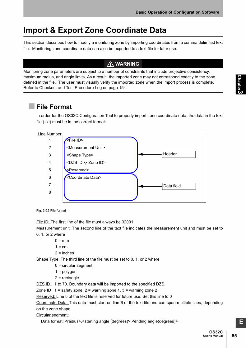
55OS32C
User’s Manual
Ch
apter3
Basic Operation of Configuration Software
E
Import & Export Zone Coordinate Data
This section describes how to modify a monitoring zone by importing coordinates from a comma delimited text
file. Monitoring zone coordinate data can also be exported to a text file for later use.
Monitoring zone parameters are subject to a number of constraints that include projective consistency, maximum radius, and angle limits. As a result, the imported zone may not correspond exactly to the zone defined in the file. The user must visually verify the imported zone when the import process is complete. Refer to Checkout and Test Procedure Log on page 154.
File FormatIn order for the OS32C Configuration Tool to properly import zone coordinate data, the data in the text
file (.txt) must be in the correct format:
Fig. 3-22 File format
File ID: The first line of the file must always be 32001
Measurement unit: The second line of the text file indicates the measurement unit and must be set to
0, 1, or 2 where
0 = mm
1 = cm
2 = inches
Shape Type: The third line of the file must be set to 0, 1, or 2 where
0 = circular segment
1 = polygon
2 = rectangle
DZS ID: 1 to 70. Boundary data will be imported to the specified DZS.
Zone ID: 1 = safety zone, 2 = warning zone 1, 3 = warning zone 2
Reserved: Line 5 of the text file is reserved for future use. Set this line to 0
Coordinate Data: This data must start on line 6 of the text file and can span multiple lines, depending
on the zone shape:
Circular segment:
Data format: <radius>,<starting angle (degrees)>,<ending angle(degrees)>
Line Number
1 <File ID>
2 <Measurement Unit>
3 <Shape Type>
4 <DZS ID>,<Zone ID>
5 <Reserved>
6 <Coordinate Data>
7
8
Header
Data field

56
Ch
apter3
OS32CUser’s Manual
Basic Operation of Configuration Software
Where the specified zone shape begins at <starting angle(degrees)> and moves in a counter-
clockwise direction and ends at <ending angle(degrees)>. Specifying a negative angle is permitted.
If the described zone falls within the area between 225˚ and 315˚, the configuration tool will offer to
correct the zone so that the imported zone falls within the minimum and maximum angular
boundaries of the scanner.
Fig. 3-23 Circular segment
Here is an example of a file specifying a circular segment with 2000mm radius starting at 340˚ and
ending at 180˚, It is designated to be written to the safety zone of zone set one.
Fig. 3-24 Textfile for circular segment
Line Number
1 32001
2 0
3 0
4 1, 1
5 0
6 2000,340, 180
7

57OS32C
User’s Manual
Ch
apter3
Basic Operation of Configuration Software
E
This text file would result in the following zone shape:
Fig. 3-25 Circular segment from textfile
Polygon: This is specified by a list of XY coordinates of each vertex of the polygon. A minimum of 3
vertices must be specified, up to a maximum number of 677.
Data format: <x-coordinate>,<y-coordinate>
Here is an example of a file specifying a polygon with 5 vertices:
Fig. 3-26 Textfile for polygon shape
Rectangle:
Data format: <left width coordinate>,<right coordinate>,<depth>
Where:
Left width = -X direction (in the 2nd quadrant)
Right width coordinate = +X direction (1st quadrant)
Depth = +Y direction
Here is an example of a file specifying a rectangle with the width from -200.0cm to 125.5cm and a
depth of 200.4cm:
Radius = 2000mm
340˚
180˚
Line Number
1 32001
2 2
3 1
4 1, 1
5 0
6 -54.30,-23.78
7 -38.04,1.59
8 -23.10, 31.50
9 23.32,38.84
10 34.90,18.22
11

58
Ch
apter3
OS32CUser’s Manual
Basic Operation of Configuration Software
Fig. 3-27 Textfile for rectangle shape
This text file would result in the following zone shape:
Fig. 3-28 Rectangle shape from textfile
Importing Zone Coordinate Data1. Start the OS32C Configuration Tool
2. Create a new configuration or load an existing one
3. Select the destination zone where the zone coordinate data will be imported to, by selecting the zone
number and the desired safety or warning zone:
Fig. 3-29 Select Zone
4. From the Configuration menu select Edit Zone:
Fig. 3-30 Edit Zone
Line Number
1 32001
2 1
3 2
4 1, 1
5 0
6 -200.0, 125.5, 200.4
7
125.5-200.0
200.4

59OS32C
User’s Manual
Ch
apter3
Basic Operation of Configuration Software
E
5. From the Edit menu select Import Zone Data:
Fig. 3-31 Import Zone Data
6. Locate and select the file with the data to be imported.
7. The configuration tool will import the data from the text file and check the validity of the data.
If the data in the text file is not valid the configuration tool will prompt the user to correct the text file and
try again.
The configuration tool will verify the zone data in the text file:
- is within minimum and maximum range of the zone being imported to
- is within the range allowed by the selected minimum object resolution
- has valid angular boundaries (does not fall within the area between 225° and 315°)
If these criteria are not met, the configuration tool will alert the user and offer to make corrections to the
specified zone in order to meet the requirements. Example error message:
Fig. 3-32 Confirm configuration tool suggested correction
8. The following message will indicate if any zones will be over-written. Example: If the current
configuration already contains DZS #2 and the text file also contains DZS #2 to be imported. The
process will overwrite the existing zones from DZS #2.
Fig. 3-33 Zones over-written

60
Ch
apter3
OS32CUser’s Manual
Basic Operation of Configuration Software
The following message will indicate the number of new zones to be added. If the current configuration
contains one DZS (3 zones) and the text file contains data for 69 DZS’s (207 zones). The process will
create new DZS’s to import the data.
Fig. 3-34 Zones to be added
Once the configuration tool has imported and displayed the zone, verify that the imported zone
displayed is correct. Click OK to accept the imported zone shape and use this shape for the zone
selected in step 3, go to Edit select Discard Imported zone data.
Fig. 3-35 Confirm imported zones
Exporting Zone Coordinate Data1. Start the OS32C Configuration Tool
2. Create a new configuration or load an existing one
3. Select the zone to be exported, by selecting the zone number and the desired safety or warning zone:
Fig. 3-36 Select zone
4. From the Configuration menu select Edit Zone
Fig. 3-37 Edit Zone

61OS32C
User’s Manual
Ch
apter3
Basic Operation of Configuration Software
E
5. From the Edit menu select Export Zone Data:
Fig. 3-38 Export Zone Data
6. Locate and select the file where the zone data is to be written to, or enter a new filename.
7. The configuration tool will export the zone dimensions/coordinates and save the data to the file
specified in the previous step.
8. Click OK after the Configuration Tool has completed exporting the data.
Fig. 3-39 Exporting zone data completed.
RBM ZONES cannot be exported into a text file, if they are included the following message will appear.
Fig. 3-40 RBM export not allowed

62
Ch
apter3
OS32CUser’s Manual
Basic Operation of Configuration Software
Zone Set Selection and Configuration
Once the number of zone sets is defined, the configuration tool is used to program the OS32C. Zone sets can
be added one at a time.
Add a Zone1. Before adding a new zone, make sure Multiple Zone has been selected for the Monitoring Zone
parameter.
Fig. 3-41 Multi-zones
2. From the Configuration menu, select Add Zone Set.
Fig. 3-42 Add Zone
3. Confirm the zone shapes for the new zone.
Fig. 3-43 Confirm Zone Shapes

63OS32C
User’s Manual
Ch
apter3
Basic Operation of Configuration Software
E
Copy and Paste Zones Copy & Paste a Single Zone
1. From the Configuration menu, select Edit zone.
2. Select the zone to be copied (bring it to the foreground)
3. Copy the zone by either:
a) selecting the Edit menu, then select Copy Zone, or
b) clicking the copy button on the toolbar.
4. Select the zone to paste to (bring it to the foreground)
5. Paste the zone by either:
a) selecting the Edit menu, then selecting Paste Zone, or
b) clicking the paste button on the toolbar.
- Safety zones can only be copied to other safety zones. Warning zones can only be copied to other warning zones.
- If reference boundary monitoring has been configured for a zone, it will not be copied over.

64
Ch
apter3
OS32CUser’s Manual
Basic Operation of Configuration Software
Copy & Paste a Zone SetTo copy and paste a zone set (a safety zone and its corresponding two warning zones):
1. Select the destination zone number (bring to foreground).
2. Click on Define Zones tab.
3. While holding down the Ctrl key, use the left mouse button to drag and drop the desired zone set from
the Defined Zones tab, onto the destination zone.
Fig. 3-44 Drag and drop
In the above figure, zone set 2 is to be copied to zone set 1.
This method of drag and drop to copy and paste zone sets can also be used to copy and paste single zones (safety or
warning).

65OS32C
User’s Manual
Ch
apter3
Basic Operation of Configuration Software
E
Delete a Zone1. On the Defined Zones tab, right-click on the zone to be deleted.
2. Select Delete Zone.
Fig. 3-45 Delete Zone

66
Ch
apter3
OS32CUser’s Manual
Basic Operation of Configuration Software
Zone Set Input Selection
Once you have determined the number of zone sets required for your application, you will need to determine
the number of inputs you will use and the zone set select input states associated with each zone set. Fig. 3-46
illustrates the use of five inputs and how they apply to the five selected zones.
Left click on a light bulb to toggle it on/off to customize the zone input combos.
Click Verify Combos to check that zone input combos are valid and that there are no duplicates.
Click Default Combo to revert zone input combos to default combos.
The combination of required inputs can be customized by the installer. This configuration uses the recommended Default
combinations.
Fig. 3-46 Zone Set Select
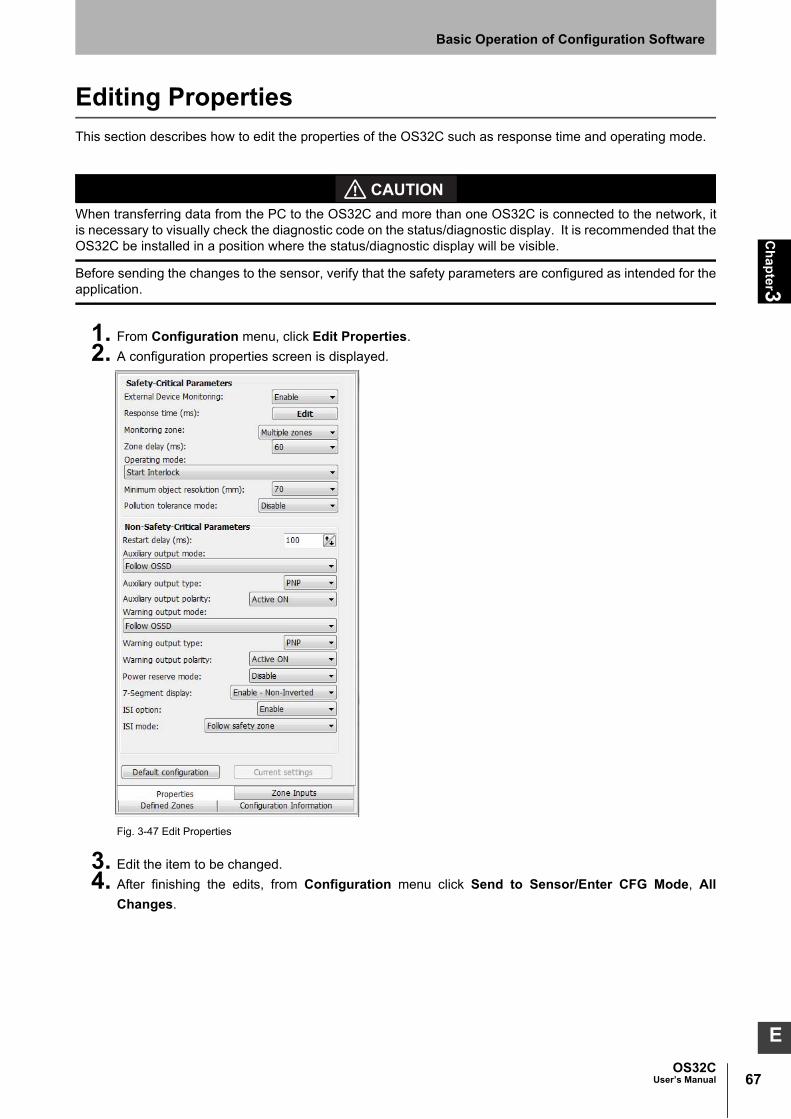
67OS32C
User’s Manual
Ch
apter3
Basic Operation of Configuration Software
E
Editing Properties
This section describes how to edit the properties of the OS32C such as response time and operating mode.
When transferring data from the PC to the OS32C and more than one OS32C is connected to the network, itis necessary to visually check the diagnostic code on the status/diagnostic display. It is recommended that theOS32C be installed in a position where the status/diagnostic display will be visible.
Before sending the changes to the sensor, verify that the safety parameters are configured as intended for theapplication.
1. From Configuration menu, click Edit Properties.
2. A configuration properties screen is displayed.
Fig. 3-47 Edit Properties
3. Edit the item to be changed.
4. After finishing the edits, from Configuration menu click Send to Sensor/Enter CFG Mode, All
Changes.

68
Ch
apter3
OS32CUser’s Manual
Basic Operation of Configuration Software
5. The screen shown below is displayed. Click Yes to confirm.
Fig. 3-48 Save Configuration to Sensor
6. When the configuration tool detects multiple scanners on a network, the user will be prompted to enter
a 4-digit code from the seven-segment display of the scanner being configured. The order in which
each two-digit pair is entered does not matter.
Fig. 3-49 Visual Scanner Identification
When the configuration tool detects only one scanner on the network, the user will be prompted to
confirm that the computer is connected to only one scanner. When this happens, the user will not need
to enter the 4-digit Visual Sensor Identification code when making changes to the scanner.
Fig. 3-50 Directly connected

69OS32C
User’s Manual
Ch
apter3
Basic Operation of Configuration Software
E
7. A confirmation message is displayed, showing the changed configuration parameters. After careful
review click Confirm to accept.
Fig. 3-51 Configuration Confirmation
8. A message shown below is displayed for confirmation of zone configuration edits. Clicking Refresh
Scan Zone displays new scanning zone information of the OS32C on the screen. Click Yes to confirm
the configured zone. If a configured zone has not changed, this message will not appear.
Fig. 3-52 Confirming Zone Configuration
9. After transmission is finished, the window shown below is displayed. Click Yes to confirm. If you do not
want to register the configuration, click No.
Fig. 3-53 Write Configuration

70
Ch
apter3
OS32CUser’s Manual
Basic Operation of Configuration Software
10. The screen shown below is displayed while the OS32C resets.
Fig. 3-54 Reset
The configuration is now complete.
If writing cannot be done, wiring may be wrong. Refer to Chapter 5 to correct wiring.

71OS32C
User’s Manual
Ch
apter3
Basic Operation of Configuration Software
E
Editing Monitor Zones
This section describes how to edit and register the changes made to the zone configurations to the OS32C.
1. From Configuration menu, click Edit Zones.
2. From Zone Set of the tool bar, select a zone set to edit. Then select a zone to edit from Foreground.
(In this example, Safety zone and Zone 1 are selcted.)
Fig. 3-55 Edit Zones
When a scanner enters zone configuration mode, the zone scanned by the OS32C is displayed. If you do not want to
display scanning zone information in the zone configuration mode, select Options from the Utility menu, and
unselect Shows scan zone in edit mode.
3. A monitoring zone can be edited by:
a) Moving a point
Click a point of the circular segment, polygon, or rectangle you want to move and drag it where you
want to place it.
b) Changing a zone shape
From Edit menu, select Convert Shape To. Select the new shape
c) Sculpting
Sculpting & Reference Boundary Monitoring p.74
d) Changing the scan angle
To change the scan/detection angle of a zone:

72
Ch
apter3
OS32CUser’s Manual
Basic Operation of Configuration Software
1. Select the zone to be changed.
2. From the Configuration menu, select Edit Zone.
3. Adjust the scan angle by moving either of the outermost points of the zone. In each of the figures
below, the two bottom-most points can be used to adjust the scan angle of the zone. The scan
angel can be as small as 45 deg. or as large as 270 deg.
Fig. 3-56 Circular Segment
Fig. 3-57 Polygon Shape
For polygon and sculpted shapes, the user can add or remove points from the zone shapes:
a) To add a point: double-click on the zone to add a point.
b) To add a point by specifying a coordinate:
i) Right-click on the zone and select Creating a point by coordinate
Fig. 3-58 Create a Point by Coordinate
ii) Specify the x-y coordinates for the location of the new point
Fig. 3-59 Specify x-y coordinates
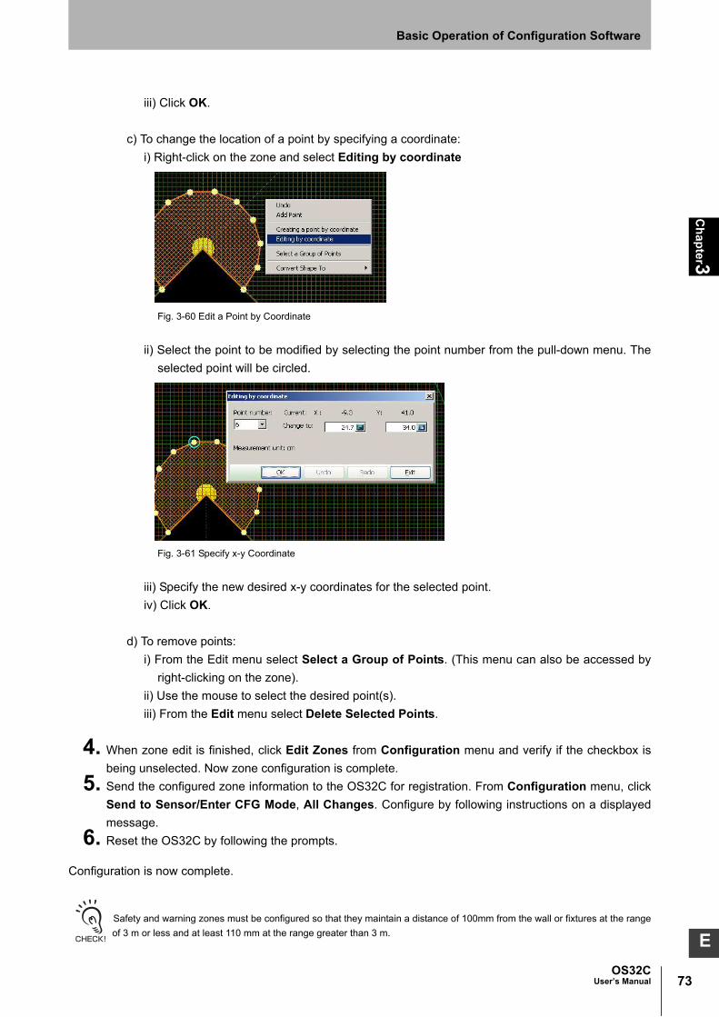
73OS32C
User’s Manual
Ch
apter3
Basic Operation of Configuration Software
E
iii) Click OK.
c) To change the location of a point by specifying a coordinate:
i) Right-click on the zone and select Editing by coordinate
Fig. 3-60 Edit a Point by Coordinate
ii) Select the point to be modified by selecting the point number from the pull-down menu. The
selected point will be circled.
Fig. 3-61 Specify x-y Coordinate
iii) Specify the new desired x-y coordinates for the selected point.
iv) Click OK.
d) To remove points:
i) From the Edit menu select Select a Group of Points. (This menu can also be accessed by
right-clicking on the zone).
ii) Use the mouse to select the desired point(s).
iii) From the Edit menu select Delete Selected Points.
4. When zone edit is finished, click Edit Zones from Configuration menu and verify if the checkbox is
being unselected. Now zone configuration is complete.
5. Send the configured zone information to the OS32C for registration. From Configuration menu, click
Send to Sensor/Enter CFG Mode, All Changes. Configure by following instructions on a displayed
message.
6. Reset the OS32C by following the prompts.
Configuration is now complete.
Safety and warning zones must be configured so that they maintain a distance of 100mm from the wall or fixtures at the range
of 3 m or less and at least 110 mm at the range greater than 3 m.

74
Ch
apter3
OS32CUser’s Manual
Basic Operation of Configuration Software
Sculpting & Reference Boundary Monitoring
The scanning zone information from the OS32C can be used for zone configuration. The desired safety zone
can be traced within the scanning range of the OS32C. Zone configuration based on this data is called
sculpting.
To configure a zone with sculpting, follow the steps shown below.
1. From the Configuration menu, select Sculpting.
2. The sculpting data displayed on the screen is based on the scanning information sent from the OS32C.
Move an object (such as a test piece) around the perimeter of the zone under configuration. The
position where the object is detected closest to the OS32C is used as the sculpting data.
Fig. 3-62 Sculpting Mode
3. To redo the configuration, exit sculpting mode by clicking the Cancel button on the Save Sculpting
Data window, and re-entering sculpting mode.
Fig. 3-63 Save Sculpting Data Window
4. If sculpting data displayed on the screen is correct, select the zone to which the configured sculpting
data is to be assigned by using the pull-down menus in the Save Sculpting Data window. Click the
Save or Edit Zone button.

75OS32C
User’s Manual
Ch
apter3
Basic Operation of Configuration Software
E
5. To enable Reference Bounding Monitoring (RBM), select the desired zone for RBM and then click the
Start RBM Sculpting button.
6. The scanner will then take approximately 50 seconds to measure the boundary. It is important not to
change the boundary during this time since the scanner will be re-scanning the area and taking an
average of the distances.
Fig. 3-64 Learning the Boundary
Fig. 3-65 Learning the Boundary Complete
7. Select the points to be used for RBM:
a. To select all the points in the zone for RBM
•Right-click on the display screen and select Set All as Reference Boundary.
Fig. 3-66 Set All as Reference Boundary

76
Ch
apter3
OS32CUser’s Manual
Basic Operation of Configuration Software
b. To select a group of points to be used for RBM:
•Right-click on the display screen and select Select a Group of Points.
Fig. 3-67 Select Group of Points
•Right-click on the display screen again and select Set Point as Reference Boundary.
Fig. 3-68 Set Points as Reference Boundary Points
•Repeat as needed.
c. To cancel RBM for the zone,
•Right-click on the display screen and select Set All as Non-Reference Boundary and select Save
Reference Boundary Setting.
Fig. 3-69 Cancel RBM Settings

77OS32C
User’s Manual
Ch
apter3
Basic Operation of Configuration Software
E
8. When done selecting the points for RBM, right-click on the display screen and select Save Reference
Boundary Setting.
Fig. 3-70 Save Reference Boundary Setting
9. Now that the Reference Boundary is set, click OK at the prompt shown below.
Fig. 3-71
10. Specify the allowed tolerance for RBM.
Fig. 3-72 RBM Tolerance
11. Send the created zone information to the OS32C for registration. From the Configuration menu, click
Send to Sensor/Enter CFG Mode, All Changes. Configure by following the instructions displayed.

78
Ch
apter3
OS32CUser’s Manual
Basic Operation of Configuration Software
Fig. 3-73 Send to Sensor
12. Follow the prompt to reset the OS32C. Now configuration is complete.
- Safety and warning zones must be configured so that they maintain a distance of 100mm from the wall or fixtures at the
range of 3 m or less and at least 110 mm at the range greater than 3 m.
- While executing the [Sculpting] command, a warning zone cannot be set with the range exceeding 10 meters (when using
the OS32C-XX-4M warning zones can not exceed 15 meters). Use [Edit Zones] or [Convert Shape To] command to modify
the shape of the warning zone.
13. A message will appear during monitoring mode, indicating that the zone contains Reference Boundary
Regions.
Fig. 3-74 Reference Boundary Monitoring indication

79OS32C
User’s Manual
Ch
apter3
Basic Operation of Configuration Software
E
Monitor Mode
The configuration software can display scanning zone information of the OS32C in real-time without stopping
the machine. The monitor mode can be used by logging on to the OS32C with either operator, maintenance,
or supervisor access level.
To start the monitor mode, select System Monitoring from the Utilities menu. To terminate, follow the same
step and deselect System Monitoring.
Fig. 3-75 System Monitoring
The outmost border indicates a scanning zone of the OS32C on the monitoring screen. A zone marked in pink
indicates the intruded area in the warning zone 1, a zone marked in yellow indicates the intruded area in the
warning zone 2, while a zone marked in red indicates the intruded area in the safety zone. The zone selected
in Foreground is displayed as purple line.
Under the monitor mode, the OS32C state is displayed on the main tool bar.
During the monitor mode you will also see the status of the OSSDs, Warning and Auxiliary outputs, the Zone
selection input status and the Seven-segment display on the rotation tool bar.
Fig. 3-76 System monitoring status

80
Ch
apter3
OS32CUser’s Manual
Basic Operation of Configuration Software
Record System Monitoring
Live system monitoring can be recorded to a file. This option is only available after successfully logging on to
the scanner in either operator or supervisor mode. The user can specify where the recording is to be saved as
well as the recording duration. In addition, Triggered recording will take a snap shot recording (20 frames)
when an intrusion occurs.
- Recording will not be interrupted if the PC goes into screensaver mode.
- Minimum recording duration is 5 seconds. Maximum recording duration is determined by the type of storage device. NTFS
type storage devices will have a 96 hour limit. FAT32 type storage devices will have a limit of 4 hours.
- Recording to a rewritable CD is not recommended because it will not be able to write data quickly enough.
To record the live monitoring:
1. From the Utilities menu, select Record System Monitoring.
2. Select the preferred recording type. Specify the desired duration or number of frames for the recording
and where the recording is to be saved.
When select ”Triggered by system event”, make sure to select at least one type of trigger.
Fig. 3-77 Full recording
Fig. 3-78 Event Triggered Recording

81OS32C
User’s Manual
Ch
apter3
Basic Operation of Configuration Software
E
3. Click OK.
4. Using the recording controls, the recording duration can be extended in increments of 15s, 30s, 45s, or
1min-5min. Recording can also be stopped at anytime.
Fig. 3-79 Recording controls
5. If no event is detected during the Event Triggered Recording, no monitoring data will be written to the
file. When user selects the file to playback, following message is displayed.
Fig. 3-80 No monitoring data playback
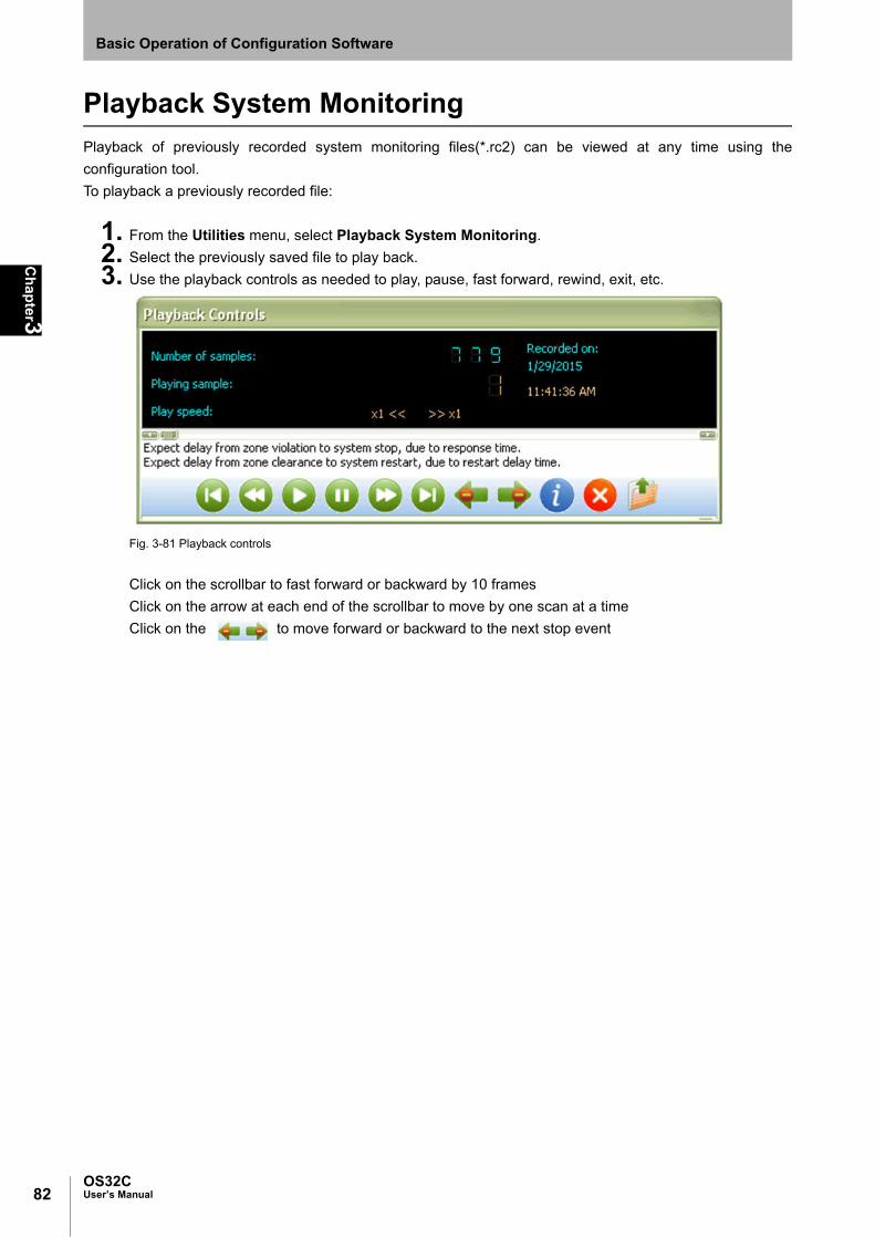
82
Ch
apter3
OS32CUser’s Manual
Basic Operation of Configuration Software
Playback System Monitoring
Playback of previously recorded system monitoring files(*.rc2) can be viewed at any time using the
configuration tool.
To playback a previously recorded file:
1. From the Utilities menu, select Playback System Monitoring.
2. Select the previously saved file to play back.
3. Use the playback controls as needed to play, pause, fast forward, rewind, exit, etc.
Fig. 3-81 Playback controls
Click on the scrollbar to fast forward or backward by 10 frames
Click on the arrow at each end of the scrollbar to move by one scan at a time
Click on the to move forward or backward to the next stop event

83OS32C
User’s Manual
Ch
apter3
Basic Operation of Configuration Software
E
Read Fault Log
There are separate fault logs for the sensor block and for the IO block. Each fault log contains the most recent
100 faults that have occurred. Fault entries are shown with the most recent faults first, so fault entry #1 is the
oldest fault.
To retrieve a fault log:
1. From the Utilities menu, select Read Fault Log.
2. Select sensor block or IO Block.
3. Print or save the error log to a text file.The example below is shown in printed form. When saved to a
text file, the data can later be exported to a spreadsheet.
Fig. 3-82 Fault Log
Page 1 of 10
Omron Scientific Technologies, Inc.
OS32C Configuration Tool - Version 1.7.10
Wednesday, July 31, 2013 - 09:15:31 AM
System Information
Sensor block serial#: AS00457S
I/O block serial#: AS00457B
Firmware version: 3.12
Model: OS32C_STANDARD
Minimum CFG Tool version: 1.5.0
FPGA version: 1.0
Compatible FPGA version: 1.0
Chronometer (h:mm): 1220:04
Product series: OS32C
Sensor name: Scanner at the corner
Angular resolution: 0.4°
Minimum object resolution (cm): 7.0
Ethernet Configuration
IP address: 192.168.40.100
Subnet mask: 255.255.255.0
Default gateway: 192.168.40.5
DHCP: Enable
MAC address: 00-0C-51-02-00-EE
Fault Log - Sensor block
Fault entry 41: 0x72 ZONE_SELECT_NUM_ACTIVE_FAULT
Description: Incorrect number of active zone set select inputs (hard fault code after diagnostic code 70 above persists for
more than 10 minutes).
Countermeasure 1: Check zone set select input connection and wiring and zone selection and zone delay configuration.
Countermeasure 2: Call Tech Support.
Category: 0x01 CRITICAL_MFG Chronometer (h:mm): 849:19
System state: STOP Temperature (°C): 30
Firmware version: 2.12 FPGA version: 1.0
Sensor block serial#: AS00457S I/O block serial#: AS00457B
Reference code: 0100-01554
Fault entry 40: 0x72 ZONE_SELECT_NUM_ACTIVE_FAULT
Description: Incorrect number of active zone set select inputs (hard fault code after diagnostic code 70 above persists for
more than 10 minutes).
Countermeasure 1: Check zone set select input connection and wiring and zone selection and zone delay configuration.
Countermeasure 2: Call Tech Support.
Category: 0x01 CRITICAL_MFG Chronometer (h:mm): 849:09
System state: STOP Temperature (°C): 30
Firmware version: 2.12 FPGA version: 1.0
Sensor block serial#: AS00457S I/O block serial#: AS00457B
Reference code: 0100-01554
Fault entry 39: 0x72 ZONE_SELECT_NUM_ACTIVE_FAULT
Description: Incorrect number of active zone set select inputs (hard fault code after diagnostic code 70 above persists for

84
Ch
apter3
OS32CUser’s Manual
Basic Operation of Configuration Software
Window Calibration
If the scan window of the OS32C is replaced, window calibration needs to be performed. Do not execute
window calibration except when the scan window is replaced.
The window calibration procedure measures the contamination level of the OS32C scan window to reset the
threshold values of window transmittance, which serves as a reference for window contamination warning
detection. To execute this procedure, the user must log on with the supervisory access level.
The calibration procedure must only be performed by qualified personnel. Before performing window calibration of the new scan window, make sure the window is clean and free from scratch, dust, and finger print. The window calibration procedure must be performed at ambient temperature 5 to 35°C. Failure to inspect the window or set the proper environmental condition during window calibration procedure may cause a reduction in the detection capability of the scanner.
The following steps describe this process:
1. From Utilities menu, select Window Calibration.
2. A screen shown below is displayed. Click OK to confirm.
Fig. 3-83 Window Calibration
3. When window calibration starts, the window shown below is displayed.
Fig. 3-84 Calibration Starts

85OS32C
User’s Manual
Ch
apter3
Basic Operation of Configuration Software
E
4. When calibration is successfully completed, the window shown below is displayed. Click Save to
confirm.
Fig. 3-85 Calibration Success
Confirm that the window calibration data has changed, and wait for the OS32C to reset. Calibration is
complete.
The window shown below may be displayed even after replacing the scan window, due to dust or finger
prints on the scan window or dust detection surface during replacement. Clean the inside and outside
of the scan window and surface of the dust detection surface using a soft cloth.
Fig. 3-86 Calibration Value too Low
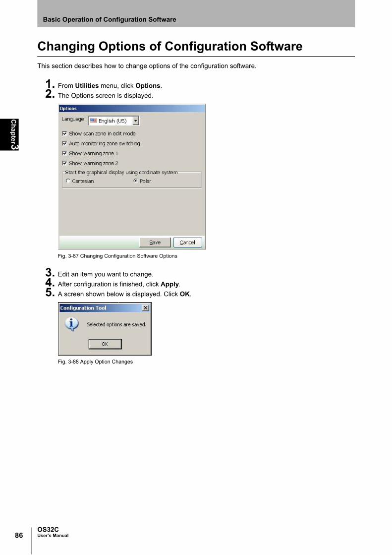
86
Ch
apter3
OS32CUser’s Manual
Basic Operation of Configuration Software
Changing Options of Configuration Software
This section describes how to change options of the configuration software.
1. From Utilities menu, click Options.
2. The Options screen is displayed.
Fig. 3-87 Changing Configuration Software Options
3. Edit an item you want to change.
4. After configuration is finished, click Apply.
5. A screen shown below is displayed. Click OK.
Fig. 3-88 Apply Option Changes

87OS32C
User’s Manual
Ch
apter3
Basic Operation of Configuration Software
E
Caution on Safety Zone Configuration
Due to the scanner’s minimum object resolution criteria, it is possible to configure zones that are not
considered valid. These zone configurations may contain a protrusion or intrusion that is narrower than 70mm
in width within the field of view. This type of invalid zone configuration can only occur within a distance of 4
meters from the scanner.
Narrow protruding areas less than 70mm wide are NOT valid zone perimeters. A scanner configured with
such a safety zone would see a presence within this area (if in monitor mode), but would not initiate a machine
stop. The following pictures shows a possible zone configuration that contains a protrusion that is narrower
then 70mm in width, since this protrusion is less than 70mm in width it will not detect a 70mm object. Refer to
Fig. 3-89
Fig. 3-89 Detection Zone in Protruding Part
Narrow intruding areas less than 70mm wide are NOT valid zone perimeters. A scanner configured with such
a safety zone would see a presence within this area (if in monitor mode), but would not initiate a machine
stop. The following pictures shows a possible zone configuration that contains an intrusion that is narrower
than 70mm in width, In this case the scanner has two fields of view and the object must be entirely in the left
or right field of view to be detected, therefore this narrow intrusion of less than 70mm in width is not a valid
zone. Refer to Fig. 3-90.
Fig. 3-90 Detection Zone in Intruding Parts

88
Ch
apter3
OS32CUser’s Manual
Basic Operation of Configuration Software
Reset to Default Configuration
This section describes how to reset the scanner back to manufacturing default configuration.
Note: This feature is available in Configuration Tool version 2.0.8 and up.
1. Log on to OS32C with supervisor level
2. From the Configuration menu, select Reset to Default Configuration
Fig. 3-91 Reset to Default Configuration
3. A screen shown below is displayed. Click Yes to proceed or No to escape.
Fig. 3-92 Confirm reset
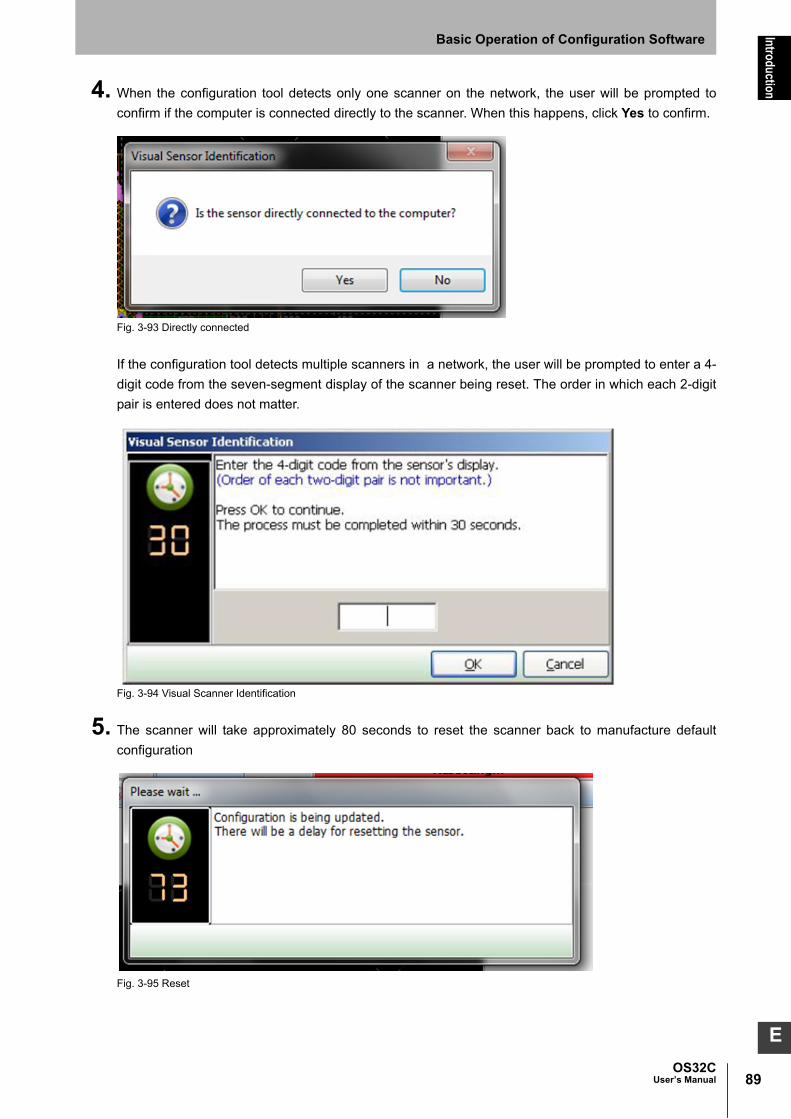
89OS32C
User’s Manual
Introduction
Basic Operation of Configuration Software
E
4. When the configuration tool detects only one scanner on the network, the user will be prompted to
confirm if the computer is connected directly to the scanner. When this happens, click Yes to confirm.
Fig. 3-93 Directly connected
If the configuration tool detects multiple scanners in a network, the user will be prompted to enter a 4-
digit code from the seven-segment display of the scanner being reset. The order in which each 2-digit
pair is entered does not matter.
Fig. 3-94 Visual Scanner Identification
5. The scanner will take approximately 80 seconds to reset the scanner back to manufacture default
configuration
Fig. 3-95 Reset

90
Introduction
OS32CUser’s Manual
Basic Operation of Configuration Software
6. Following screen will be displayed when the reset process is completed. Click Yes to retrieve the
default configuration from the scanner.
Fig. 3-96 Reset completed

Ch
ap
ter4
91OS32C
User’s Manual
E
Mounting Considerations 92
Configuring Multiple OS32C Scanners 92
Distance from Wall 94
Stationary Installation and Configuration 95
Installation for Stationary Area Scanning 95
Configuration 96
Configuration Example: Installation on a Machine (1) 97
Configuration Example: Installation on a Machine (2) 99
Configuration Example: Entry Access Protection 99
Configuration Example: Hand Detection Protection 101
Mobile Installation and Configuration 103
Applying OS32C on Automated Guided Vehicles (AGV) 103
Configuration for Automated Guided Vehicles (AGV) 105
Configuration Example: Use of an AGV 106
AGV Standards 107
External Dimensional Drawings 108
Mounting Stand 116
Ethernet Cable 117
XS5 OMRON SmartclickTM Connection 118
Chapter4 Installation

92
Ch
ap
ter4
OS32CUser’s Manual
Installation
Mounting Considerations
The OS32C must not be mounted behind glass or within a secondary enclosure. Failure to do so will cause areduction in detection capability, which can cause serious injury or death.
Operation of the OS32C may be affected by light in the environment, such as incandescent light, strobe lightand light from a photosensor using infrared light.
Operation of the OS32C may be affected by substances in the environment, such as fog, smoke, steam and other small particles.
The following considerations should be taken into account when determining the mounting location for the
OS32C. It is possible for ambient light to interfere with normal operation of the OS32C. Ambient light
interference DOES NOT lead to a loss of safety, it may, however, cause false nuisance stops of the guarded
equipment.
Some installations may require that the OS32C be mounted in direct exposure to ambient light. In these
situations you must assure that the separation between the scan plane of the OS32C and the light source be
greater than +/-5°.
Fig. 4-1 Angle between scan plane and light source
Configuring Multiple OS32C Scanners
The possibility exists that two OS32C may interfere with each other. To avoid this when using multiple
OS32C in the same location, please review the following mounting recommendations.
•Adjust the scanners to offset the scanning plane by tilting the OS32Cs.
•Adjust the scanners to offset the scanning plane by mounting the OS32Cs at different heights.
•Adjust the scanners to different scanning planes and additional sampling scans (response time) on
the OS32Cs.
•Install a barrier to block the direct path of possible signal crossing.
5° or more
5° or more

93OS32C
User’s Manual
Ch
ap
ter4
Installation
E
Fig. 4-2 Offset Scanning Level by Tilting
Fig. 4-3 Offset Parallel Scanning Levels by Different Installation Height
When installing the OS32Cs side by side, it is more effective to set their mounting heights differently. When adjusting
the OS32C tilted, it may be more effective to adjust the OS32C downward depending on the condition of the outside
light source (natural light or halogen light).
Fig. 4-4 Separation using a screen
Use of a screen may increase the effect of reflection depending on its material. Select one with matte black finish that
is resistant to reflection.
Detection Plane
5°or more 5°or more
Detection Plane
5°or more
Detection Plane
5°or more
Top View
Front View
Screen

94
Ch
ap
ter4
OS32CUser’s Manual
Installation
Distance from Wall
The safety or warning zones must be configured so that they maintain a distance of 100mm from the wall or
tooling fixture at the range of 3 m or less and at least 110 mm at the range greater than 3 m.
If sculpting is performed, the distance is automatically configured with a stand-off distance of 100mm from
walls at the range of 3 m or less and at least 110 mm at the range greater than 3 m.
Fig. 4-5 Distance from Wall
Wall
100 mm or longer
(at range of 3 m or less)
110 mm or longer
(at range of greater than 3 m)
100 mm or longer (at range of 3 m or less)110 mm or longer (at range of greater than 3 m)
Safety zone or warning zone

95OS32C
User’s Manual
Ch
ap
ter4
Installation
E
Stationary Installation and Configuration
Installation for Stationary Area Scanning Position
The OS32C must always be installed in a position that the safety zone can cover the danger area
being scanned.
Area which cannot be scanned (e.g. behind obstacles) must be secured by taking appropriate
additional measures (e.g. barriers).
The reset switch for clearing interlock must be positioned in such a way that the entire monitoring zone
is in view and the operating element cannot be reached from inside the monitored zone.
Installation Height (Detection Level)The installation mounting height of the OS32C is very important, and the following considerations
should be taken into account to determine the mounting height.
The OS32C must be mounted in such a way to prevent access to the hazardous area, personnel
should not be able to crawl under, stand behind or climb over the protective field. According to ISO
13855 (described later), for an installation height exceeding 300mm, the possibility of creeping under
the protective field must be taken into account.
Always mount the OS32C so that it is protected from moisture and dirt. Mount the scanner so that the
indicators are visible. Avoid locations where the OS32C is exposed to excessive shock and vibration.
Fig. 4-6 Installation Height
Scanning level
H

96
Ch
ap
ter4
OS32CUser’s Manual
Installation
ConfigurationWhen using the OS32C to detect the hazardous area, the Start/Restart Interlock mode should be
selected; the regulations applying to the machine must also be complied with.
Safety Distance (Required Depth of Safety Zone)Always configure the safety zone in such a way that the machine comes to a standstill in a time less
than that taken to reach the danger point of the machine after infringing (interrupting) the safety zone.
The standard ISO 13855-2005 (EN 999-1998) must be used to calculate the minimum safety distance;
according to ISO 13855-2005 (EN 999-1998), the minimum safety distance, S, from the danger zone
area to the outer edge of the safety zone is calculated as follows:
S = (K x T) + C + Z
where:
S = Minimum safety distance in mm measured from the danger area to the outer contour of the safety zone.
K = Movement or approach speed in mm/s (constant K = 1600 mm/s)
T = Delay between interruption of the safety zone and standstill of the machine in seconds consisting
of the sum of t1, t2 and t3:
t1 = Response time of the OS32C
t2 = Rundown time of the machine (mechanical rundown, reaction time of control system)
t3 = additional time delay for use when multiple zones are used (t3 = 10 ms.)
C = Safety constant with C = 1200 mm - 0.4 x H (C ≥ 850); where
H = Distance of detection level from reference level in mm
Z = Additional safety factors (maximum measurement error) (Z = Z1 + Z2),
Z1 = The OS32C's maximum measurement error (100 mm at a range of 3 m or less and 110 mm at
a range of greater than 3 m)
Z2 = Additional error by reflective background ( Additional Error due to Reflective Background
p.139 )
Documentation of Configuration ParametersThe person responsible for the set-up must record the configuration parameters, print out and sign the
report.
•Connect the printer to the PC.
•Select the menu "File/Print Configuration" in the configuration software.
•The report is printed out.
•Sign and date the report and file it in a known location which is always accessible.
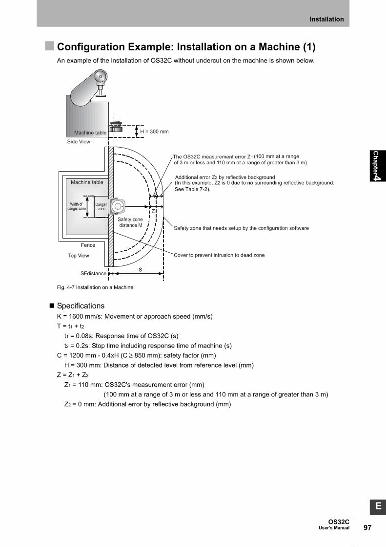
97OS32C
User’s Manual
Ch
ap
ter4
Installation
E
Configuration Example: Installation on a Machine (1)An example of the installation of OS32C without undercut on the machine is shown below.
Fig. 4-7 Installation on a Machine
SpecificationsK = 1600 mm/s: Movement or approach speed (mm/s)
T = t1 + t2
t1 = 0.08s: Response time of OS32C (s)
t2 = 0.2s: Stop time including response time of machine (s)
C = 1200 mm - 0.4xH (C ≥ 850 mm): safety factor (mm)
H = 300 mm: Distance of detected level from reference level (mm)
Z = Z1 + Z2
Z1 = 110 mm: OS32C's measurement error (mm)
(100 mm at a range of 3 m or less and 110 mm at a range of greater than 3 m)
Z2 = 0 mm: Additional error by reflective background (mm)
SFdistanceS
Fence
Top View
Width of danger zone Z
H = 300 mm
Safety zone distance M
The OS32C measurement error Z1 (100 mm at a range of 3 m or less and 110 mm at a range of greater than 3 m)
Safety zone that needs setup by the configuration software
Cover to prevent intrusion to dead zone
Machine table
Machine table
Side View
Danger zone
Additional error Z2 by reflective background (In this example, Z2 is 0 due to no surrounding reflective background.See Table 7-2).

98
Ch
ap
ter4
OS32CUser’s Manual
Installation
Calculation Example of Safety Distance SS = (K x T) + C + Z
= 1600 mm/s x (0.08 s+0.2 s) + (1200 mm - (0.4 x 300 mm)) + 110 mm *
= 448 mm + 1080 mm +110 mm *
= 1638 mm
*100 mm at a range of 3 m or less and 110 mm at a range of greater than 3 m
There are several different ways to install the OS32C as shown in Fig. 4-8. Each length of SFdistance
(the potential dead space indicated in Fig. 4-7 between the OS32C and the danger zone) is different.
Fig. 4-8 Dimensions of SFdistance
Take additional precautions to prevent intrusion to the dead zone after determining how to mount the
OS32C.
Additional Error Z2 due to Reflective Background(1) High-reflective background material or object is present in the scanning plane and within 1.2m
beyond the safety zone.
(e.g. acrylic panel, stainless steel, reflective tape, mirror)
(2) Low-reflective background material or object is present in the scanning plane and within 1.2m
beyond the safety zone.
(e.g. paint-finished equipment)
If any of the conditions listed above apply to your application, an additional error factor Z2 should be
added to the safety zone.
Additional Error due to Reflective Background p.139
111.4mm97.7mm90.4mm
OS32C only OS32C with OS32C-BKT1 OS32C with OS32C-BKT1 & OS32C-BKT2 OS32C with OS32C-BKT3
103.4mm
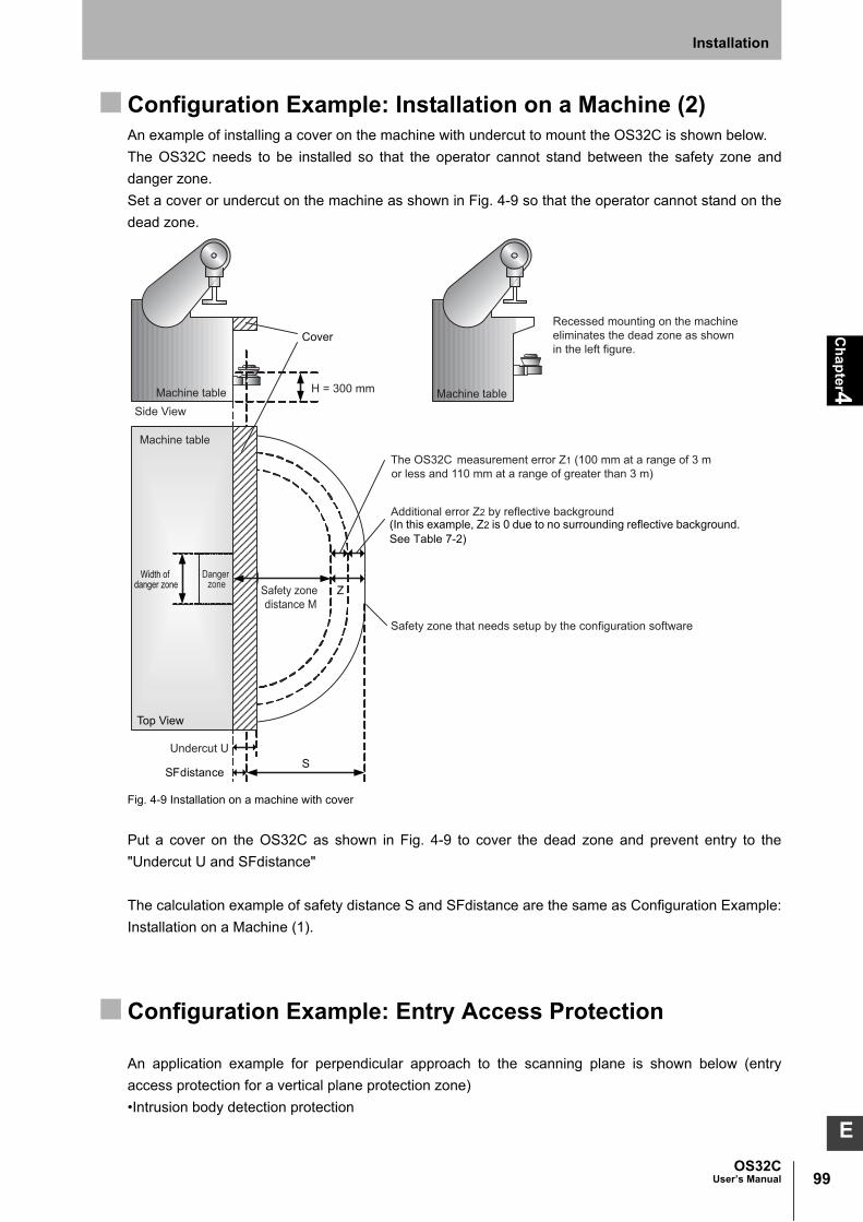
99OS32C
User’s Manual
Ch
ap
ter4
Installation
E
Configuration Example: Installation on a Machine (2)An example of installing a cover on the machine with undercut to mount the OS32C is shown below.
The OS32C needs to be installed so that the operator cannot stand between the safety zone and
danger zone.
Set a cover or undercut on the machine as shown in Fig. 4-9 so that the operator cannot stand on the
dead zone.
Fig. 4-9 Installation on a machine with cover
Put a cover on the OS32C as shown in Fig. 4-9 to cover the dead zone and prevent entry to the
"Undercut U and SFdistance"
The calculation example of safety distance S and SFdistance are the same as Configuration Example:
Installation on a Machine (1).
Configuration Example: Entry Access Protection
An application example for perpendicular approach to the scanning plane is shown below (entry
access protection for a vertical plane protection zone)
•Intrusion body detection protection
S
Z
Cover
SFdistance
H = 300 mm
Recessed mounting on the machine eliminates the dead zone as shown in the left figure.
Top View
Width of danger zone Safety zone
distance M
The OS32C measurement error Z1 (100 mm at a range of 3 m or less and 110 mm at a range of greater than 3 m)
Safety zone that needs setup by the configuration software
Machine table
Machine table
Side View
Danger zone
Undercut U
Machine table
Additional error Z2 by reflective background(In this example, Z2 is 0 due to no surrounding reflective background.See Table 7-2)

100
Ch
ap
ter4
OS32CUser’s Manual
Installation
•Reference Boundary Monitoring (RBM) must be applied when the OS32C is used for Entry Access
Protection guarding as specified in IEC61496-3:2008.
Refer to page 22 for more information on RBM.
•To ensure adequate detection a response time of 80 mS is required. If the response time exceeds
80mS, a 70 mm object with a speed of 1.6 m/s may not be detected under certain circumstances.
•Additional counter measures for protection must be provided if there is a space between the
protection zone and the machine hazard point.
Fig. 4-10 Perpendicular Approach Installation
S = (K x T) + C
S = Minimum safety distance in mm measured from the danger area to the outer contour of the safety
zone.
K = Movement or approach speed in mm/s (constant K = 1600 mm/s)
T = Delay between interruption of the safety zone and standstill of the machine in seconds consisting
of the sum of t1 and t2.
t1 = Response time of the OS32C
t2 = Rundown time of the machine (mechanical rundown, reaction time of control system).
C = Additional supplemental distance in millimeters
Example of safety distance calculationK = 1600 mm/s approach speed constant
T = t1 + t2 = 0.58s Overall response time
t1 = 0.08 seconds OS32C response time (adjustable)
t2 = 0.5 seconds Max. time required to full stop of the machine
C = 850mm
S = K x T + C = 1600 x 0.58 + 850 = 1778 mm
Protective Field
Contour of the floor as reference
S
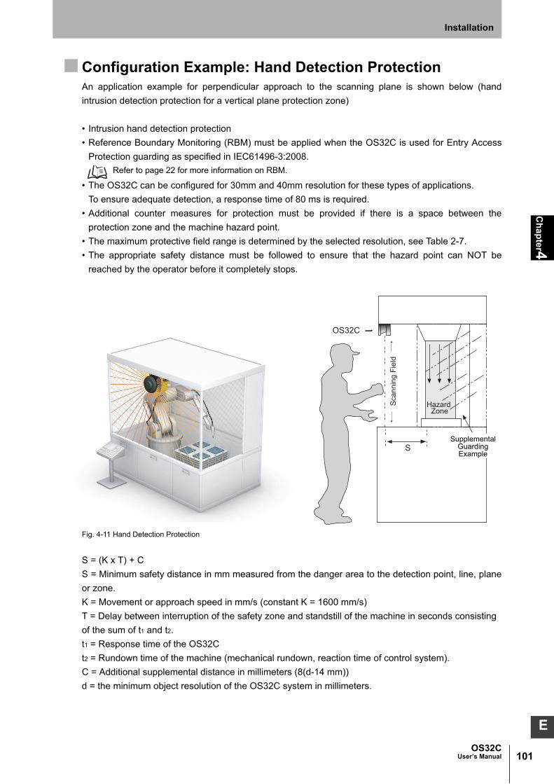
101OS32C
User’s Manual
Ch
ap
ter4
Installation
E
Configuration Example: Hand Detection ProtectionAn application example for perpendicular approach to the scanning plane is shown below (hand
intrusion detection protection for a vertical plane protection zone)
• Intrusion hand detection protection
• Reference Boundary Monitoring (RBM) must be applied when the OS32C is used for Entry Access
Protection guarding as specified in IEC61496-3:2008.
Refer to page 22 for more information on RBM.
• The OS32C can be configured for 30mm and 40mm resolution for these types of applications.
To ensure adequate detection, a response time of 80 ms is required.
• Additional counter measures for protection must be provided if there is a space between the
protection zone and the machine hazard point.
• The maximum protective field range is determined by the selected resolution, see Table 2-7.
• The appropriate safety distance must be followed to ensure that the hazard point can NOT be
reached by the operator before it completely stops.
Fig. 4-11 Hand Detection Protection
S = (K x T) + C
S = Minimum safety distance in mm measured from the danger area to the detection point, line, plane
or zone.
K = Movement or approach speed in mm/s (constant K = 1600 mm/s)
T = Delay between interruption of the safety zone and standstill of the machine in seconds consisting
of the sum of t1 and t2.
t1 = Response time of the OS32C
t2 = Rundown time of the machine (mechanical rundown, reaction time of control system).
C = Additional supplemental distance in millimeters (8(d-14 mm))
d = the minimum object resolution of the OS32C system in millimeters.
Hazard Zone
S
OS32C
SupplementalGuardingExample
Sca
nnin
g Fi
eld

102
Ch
ap
ter4
OS32CUser’s Manual
Installation
Example of safety distance calculation for 30mm resolutionK = 1600 mm/s approach speed constant
T = t1+t2 = 0.58s Overall response time
t1 = 0.08 seconds OS32C response time (adjustable)
t2 = 0.5 seconds Max. time required to full stop of the machine
C = 8(30-14 mm)
S = K x T + C = 1600 x 0.58 + 128 = 1056 mm
If the calculated value is more than 500mm, use it for your application installation. The minimum value
of S should not be less than 500mm.
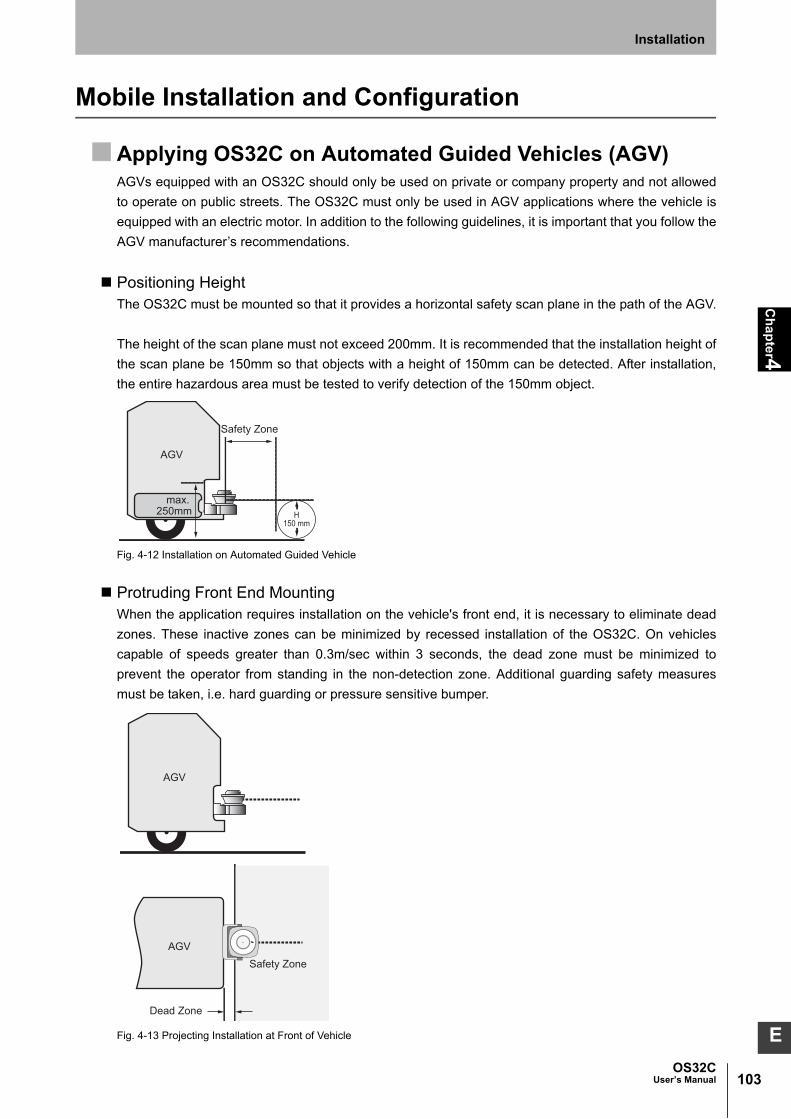
103OS32C
User’s Manual
Ch
ap
ter4
Installation
E
Mobile Installation and Configuration
Applying OS32C on Automated Guided Vehicles (AGV)AGVs equipped with an OS32C should only be used on private or company property and not allowed
to operate on public streets. The OS32C must only be used in AGV applications where the vehicle is
equipped with an electric motor. In addition to the following guidelines, it is important that you follow the
AGV manufacturer’s recommendations.
Positioning HeightThe OS32C must be mounted so that it provides a horizontal safety scan plane in the path of the AGV.
The height of the scan plane must not exceed 200mm. It is recommended that the installation height of
the scan plane be 150mm so that objects with a height of 150mm can be detected. After installation,
the entire hazardous area must be tested to verify detection of the 150mm object.
Fig. 4-12 Installation on Automated Guided Vehicle
Protruding Front End MountingWhen the application requires installation on the vehicle's front end, it is necessary to eliminate dead
zones. These inactive zones can be minimized by recessed installation of the OS32C. On vehicles
capable of speeds greater than 0.3m/sec within 3 seconds, the dead zone must be minimized to
prevent the operator from standing in the non-detection zone. Additional guarding safety measures
must be taken, i.e. hard guarding or pressure sensitive bumper.
Fig. 4-13 Projecting Installation at Front of Vehicle
Safety Zone
AGV
max. 250mm H
150 mm
Dead Zone
Safety Zone
AGV
AGV

104
Ch
ap
ter4
OS32CUser’s Manual
Installation
Recessed Front End MountingAlthough a recessed installation reduces the size of the dead zone, in some cases this technique
creates dead angles. If the OS32C is mounted too deep within the vehicle, the OS32C will not be able
to properly scan the hazardous area. These areas are referred to as Dead Angles, as shown in Fig. 4-
14. On vehicles capable of speeds greater than 0.3m/sec within 3 seconds, additional safety measures
must be taken.
Fig. 4-14 Installation with Bodywork of AGV
Installation of OS32CThere are several different ways to mount the OS32C as shown in Fig. 4-15. The DFdistance (the
minimum required clearance when installing the OS32C in a recessed location) needs to be
considered depending on the mounting method.
Also, take additional precautions to prevent intrusion into the dead zone.
Fig. 4-15 Dimensions of DFdistance
Safety Zone
Dead Zone
AGV
Dead Zone
Dead Zone
Safety ZoneAGV
98.9mm85.2mm77.9mm
OS32C only OS32C with BKT1 OS32C with OS32C-BK1 and OS32C-BKT2
OS32C with OS32C-BKT3
90.9mm

105OS32C
User’s Manual
Ch
ap
ter4
Installation
E
Configuration for Automated Guided Vehicles (AGV) Safety Distance (Safety zone depth required for safety zone)
For calculating the minimum safety distance for AGV, the standard IEC 61496-3 can be used. The
safety distance, S, for use with an AGV should be calculated using the following formula:
S = Minimum safety distance in mm measured from the danger area to the outer contour of the safety
zone.
Sp = Maximum stopping distance for AGV (mm)
Z = Additional safety factors (maximum measurement error)
With the conditions above, the minimum safety distance S is calculated as follows:
S = Sp + Z
SP = (Vmax. x T) + Sbrake
Z = Z1 + Z2 + Zgc + Zbf
Vmax = Maximum speed of AGV in mm/s
T = Response time consisting of sum of t1, t2 and t3:
t1 = Response time of OS32C
t2 = Response time of AGV
t3 = additional time delay for use when multiple zones are used (t3 = 10 ms.)
Sbrake = Braking distance of AGV in mm based on manufacturer's document
Z1 = OS32C's measurement error (100 mm at range of 3 m or less and 110 mm at range of greater
than 3 m)
Z2 = Additional error by reflective background ( Additional Error due to Reflective Background
p.139 )
Zgc = Safety factor for lack of clearance between under surface of AGV and ground ( Fig. 4-16).
Zbf = Safe factor for reduction of brake force of the AGV through wear and usage.
Fig. 4-16 Safety Factor for Low Ground Clearance
Safety Distance (Width Required for Safety Zone)Sw = Minimum safety distance of safety zone width (mm)
Vw = Width of AGV (mm)
Z = Additional safety factors (maximum measurement error)
With the conditions above, the minimum safety distance Sw of safety zone width is calculated as
follows:
SW = VW + 2 x Z
Configured zone
AGV
Safetyfactor
Clearance between ground and under surface of AGV
50
0
100
50 100 150Safety factor Zgc (mm)
Gro
und
clea
ranc
e (m
m)

106
Ch
ap
ter4
OS32CUser’s Manual
Installation
Z = Z1 + Z2 + Zgc + Zbf
Z1 = OS32C's measurement error (100 mm at range of 3 m or less and 110 mm at range of greater
than 3 m)
Z2 = Additional error by reflective background ( Additional Error due to Reflective Background
p.139 )
Zgc = Safety factor for lack of clearance between under surface of AGV and ground ( Fig. 4-16).
Zbf = Safe factor for reduction of brake force of the AGV through wear and usage.
Configuration Example: Use of an AGV
Fig. 4-17 Installation on AGV
SpecificationsSP = 1600 mm: Maximum stopping distance of AGV
VW = 1100 mm: Width of AGV
Z1 = 110 mm: OS32C's measurement error *
Z2 = 0 mm: Additional error by reflective background (no reflective background)
Zgc = 50 mm: Safety factor for lack of clearance between under surface of AGV and ground
Zbf = 100 mm: Safe factor for reduction of brake force of the AGV through wear and usage
Installation position = Centered
Calculation Example of Safety Distance (Safety Zone Depth)S = SP + Z
= SP + Z1 + Z2 + Zgc + Zbf
= 1600 mm + 110 mm * + 0 mm + 50 mm + 100 mm
= 1860 mm
Calculation Example of Safety Distance (Safety Zone Width)SW = VW + 2 x Z
= VW + 2 x (Z1 + Z2 + Zgc + Zbf)
= 1100 mm + 2 x (110 mm * + 0 mm + 50 mm + 100 mm)
= 1620 mm
*100 mm at range of 3 m or less and 110 mm at range of greater than 3 m
AGV
Wid
th o
f saf
ety
zone
Sw
Z1
Z2
Zgc
Zbf
Wid
th o
f AG
V V
w
Wid
th o
f AG
V V
w
Length of safety zone S
Maximum stopping distance of AGV Sp Safety zone required for setup by the configuration software

107OS32C
User’s Manual
Ch
ap
ter4
Installation
E
Additional Error Z2 due to Reflective BackgroundsIf one of the conditions listed below applies to your application, an additional error factor Z2 should be
added to the safety zone.
(1) High-reflective background material or object is present in the scanning plane and within 1.2m
beyond the safety zone.
(e.g. acrylic panel, stainless steel, reflective tape, mirror)
(2) Low-reflective background material or object is present in the scanning plane and within 1.2m
beyond the safety zone.
(e.g. paint-finished equipment)
Additional Error due to Reflective Background p.139
AGV StandardsSafety and Machine standards vary from country to country and machine to machine.
The following related standards may be referenced:
•ASME/ANSI B56.5-1993
•EN 1493
•EN 1525
•IEC/EN 61496-3

108
Ch
ap
ter4
OS32CUser’s Manual
Installation
External Dimensional Drawings
OS32C with Back Location Cable Entry /with EIP and Back Location Cable Entry
(OS32C-BP/OS32C-BP-4M/OS32C-BP-DM/OS32C-BP-DM-4M)
Fig. 4-18 OS32C with Back Cable Entry Dimensional Drawing
OS32C with Side Location Cable Entry /with EIP and Side Location Cable Entry
(OS32C-SP1/OS32C-SP1-4M/OS32C-SP1-DM/OS32C-SP1-DM-4M)
Fig. 4-19 OS32C with Side Cable Entry Dimensional Drawing
M5 x 0.8, DEPTH 9.0 [0.35] MAX (x4)
M5 x 0.8, DEPTH 9.0 [0.35] MAX (x4)
18.2 [0.72]39.0 [1.54]
25.0 [0.99]

109OS32C
User’s Manual
Ch
ap
ter4
Installation
E
OS32C with Top Guard Kit Dimensional Drawing
Fig. 4-20 Dimensional drawing of OS32C with Top Guard Kit OS32C-BKT4
OS32C with Top Guard Kit Assembly Drawing
Fig. 4-21 Assembly drawing of OS32C with Top Guard Kit OS32C-BKT4
67.0 [2.64]SCAN PLANE 41.4 [1.63]
6.0 [0.24]
27.7 [1.09]
50.0 [1.97]
121.0 [4.77]
107.5 [4.24]
112.4 [4.43]
150.4 [5.93]
63.0 [2.48]
145.7 [5.74]
93.4 [3.68]
SIDE VIEWBACK VIEW
TOP VIEW
DIMENSIONS: mm [Inches]
4-5.6 [0.22] dia. 3.0 [0.12]
HARDWARE USER SUPPLIEDM5 x 0.8 MOUNTING SCREWS
(x4) MOUNTING SCREWS,
VIEW -A-
TOP GUARD

110
Ch
ap
ter4
OS32CUser’s Manual
Installation
OS32C with Simple Mounting Bracket Assembly Drawing
Fig. 4-22 Assembly drawing of OS32C with simple mounting bracket OS32C-BKT3
OS32C with Simple Mounting Bracket Dimensional Drawing
Fig. 4-23 Dimensional drawing of OS32C with simple mounting bracket OS32C-BKT3
27.7 [1.09]
(X4) (M5 x 12) MOUNTING SCREWS
(X4) SLOTS M5 SCREWS, SPLIT AND FLAT WASHERS HARDWARE USER SUPPLIED *
(X4) (M5) WASHERS, FLAT (X2)
SIMPLE MOUNTING BRACKET
OS32C LASER SCANNER UNITMODEL OS32C-BP/-BP-4M /-BP-DM/-BP-DM-4M
I/O CABLE
* In order to comply with Section 4.2.16 of IEC 61496-3, when the OS32C is mounted where the scanner position could change (e.g. as the result of an impact), additional mechanical means, such as serrated or toothed lock washers, must be employed in the mounting hardware.
MODEL OS32C-SP1/-SP1-4M/-SP1-DM/-SP1-DM-4MOS32C LASER SCANNER UNIT (TO ALLOW FOR CONNECTOR CLEARANCE).
USE OPEN END HEX WRENCH TOOL TO FASTEN SCREWSBEFORE ATTACHING THIS BRACKET TO UNIT.INSERT HEX HEAD HARDWARE INTO BRACKET SLOTS

111OS32C
User’s Manual
Ch
ap
ter4
Installation
E
OS32C with Simple Mounting Bracket and Top Guard Kit Dimensional Drawing
Fig. 4-24 Dimensional drawing of OS32C with OS32C-BKT3 and OS32C-BKT4
OS32C with Simple Mounting Bracket and Top Guard Kit Assembly Drawing
Fig. 4-25 Assembly drawing of OS32C with OS32C-BKT3 and OS32C-BKT4
(X4) (M5 x 16) MOUNTING SCREWS (X4) (M5) WASHERS, FLAT
(X2) SIMPLE MOUNTING BRACKET
OS32C LASER SCANNER UNITMODEL OS32C-BP/-BP-4M/ -BP-DM/-BP-DM-4M
TOP GUARD
I/O CABLE (X4) SLOTS M5 SCREWS, SPLIT AND FLAT WASHERS
HARDWARE USER SUPPLIED *
* In order to comply with Section 4.2.16 of IEC 61496-3, when the OS32C is mounted where the scanner position could change (e.g. as the result of an impact), additional mechanical means, such as serrated or toothed lock washers, must be employed in the mounting hardware.
MODEL OS32C-SP1/-SP1-4M/-SP1-DM/-SP1-DM-4MOS32C LASER SCANNER UNIT (TO ALLOW FOR CONNECTOR CLEARANCE).
USE OPEN END HEX WRENCH TOOL TO FASTEN SCREWSBEFORE ATTACHING THIS BRACKET TO UNIT.INSERT HEX HEAD HARDWARE INTO BRACKET SLOTS

112
Ch
ap
ter4
OS32CUser’s Manual
Installation
OS32C with Bottom/Side Mounting Brackets
Fig. 4-26 External dimensional drawing of OS32C with OS32C-BKT1
OS32C with Bottom/Side Mounting Brackets Assembly Drawing
Fig. 4-27 Assembly drawing of OS32C with OS32C-BKT1
79.2 [3.12]SCAN PLANE
39.9 [1.57]
50.0 [1.97]
116.7 [4.60]
37.9[1.49]
102.4 [4.03] 66.4 [2.62]144.4 [5.69]
106.0 [4.17]
12.2 [0.48]
155.9 [6.14]
4.9 [0.19]
24.5 [0.97]
23.3 [0.92]41.0 [1.62]
97.7 [3.85]
23.3 [0.92]54.5 [2.15]
69.2 [2.73]
103.7 [4.08]
93.7 [3.69]
BOTTOM VIEW
BACK VIEW SIDE VIEW
DIMENSIONS: mm [Inches]
4-5.3 [0.21] dia.
3-6.4 [0.25] dia.
4.2 [0.17]
(x4) (M5 x 16)MOUNTING SCREWS
VIEW -B-
WASHERS, FLAT(x4) (M5)
BOTTOM/SIDE MOUNTING BRACKET
(x4) STAND-OFFINDENTATIONS
(x4) HOLES FORM5 MOUNTING SCREWS
HARDWARE USER SUPPLIED
(x3) HOLES FORM6 MOUNTING SCREWS,
FLAT HEAD, 90 DEGHARDWARE USER SUPPLIED

113OS32C
User’s Manual
Ch
ap
ter4
Installation
E
OS32C with Bottom/Side Mounting Brackets and Top Guard Kit
Fig. 4-28 Dimensional drawing of OS32C with OS32C-BKT1 and OS32C-BKT4
OS32C with Bottom/Side Mounting Brackets and Top Guard Kit Assembly Drawing
Fig. 4-29 Assembly drawing of OS32C with OS32C-BKT1 and OS32C-BKT4
50.0 [1.97]
39.9 [1.57]
124.9 [4.92]
75.2 [2.96]
107.5 [4.24]
12.2 [0.48]
79.2 [3.12]SCAN PLANE
93.7 [3.69]
103.7 [4.08]97.7 [3.85]
24.5 [0.97]
4.9 [0.19]
37.9 [1.49]
154.7 [6.09]
102.4 [4.03]
144.4 [5.69]
23.3 [0.92]
66.4 [2.62]
54.5 [2.15]
106.0 [4.17]155.9 [6.14]
BACK VIEW SIDE VIEW
DIMENSIONS: mm [Inches]BOTTOM VIEW
23.3[0.92]41.0
[1.62]4.8 [0.19]
3-6.4 [0.25] dia.
4-5.3 [0.21] dia.
(X4) (M5 X 16)MOUNTING SCREWS
VIEW -C-
WASHERS, FLAT(X4) (M5)SCREW DIRECTION LINE
(X4) STAND-OFFINDENTATIONS
(X4) HOLES FORM5 MOUNTING SCREWS
HARDWARE USER SUPPLIED
TOP GUARD
BRACKET #1
TOP GUARD KIT
BOTTOM/SIDEMODEL OS32C-BKT1
MOUNTING KIT
MODEL OS32C-BKT4
Inches]DIMENSIONS: mm
(X3) HOLES FORM6 MOUNTING SCREWS
FLAT HEAD 90 DEGHARDWARE USER SUPPLIED

114
Ch
ap
ter4
OS32CUser’s Manual
Installation
OS32C with XY Axis Rotation Mounting Kit Dimensional Drawing
Fig. 4-30 Dimensional drawing of OS32C with OS32C-BKT1 and OS32C-BKT2
OS32C with XY Axis Rotation Mounting Kit Assembly Drawing
Fig. 4-31 Assembly drawing of OS32C with OS32C-BKT1 and OS32-BKT2
50.0 [1.97]
55.9 [2.20]
132.7 [5.23]
151.1 [5.95]
163.7 [6.45]
28.2 [1.11]
95.2 [3.75]SCAN PLANE
102.4 [4.03]
37.0 [1.46]54.5 [2.15]
119.7 [4.72]
111.4 [4.39]
93.5 [3.68]
99.2 [3.91]
17.0 [0.67]
48.0 [1.89]
46.0 [1.81]
166.3 [6.55]
163.0 [6.42]
150.5 [5.93]
43.0 [1.69]
15.0°
15.0°
42.2 [1.66]17.4 [0.69]
7.5°
7.5°
BACK VIEW
BOTTOM VIEW
SIDE VIEW
(FOR BACK MOUNTING)
HARDWARE FORY-ADJUSTMENT
(FOR Y-ANGULAR ADJUSTMENT)BACK VIEW
DIMENSIONS: mm [Inches]
4-5.3 [0.21] dia.
4-5.3 [0.21] dia.
6.4 [0.25]
2-R72.0 [2.83]
R47.5 [1.87]
HARDWARE
X-ADJUSTMENTFOR
MTG SCREWS(x3)(M5 x 10)(EACH SIDE)
WASHERS, SPLIT(x3) (M5) (EACH SIDE)
WASHERS, FLAT(x3) (M5) (EACH SIDE)
IS REQUIRED
MOUNTING UNIT,IF Y-ADJUSTMENT
Y-ADJUSTMENT.INSTALL BEFORE
HARDWARE FOR
WASHER, FLAT
(x1) (M5)WASHER, SPLIT
MTG SCREW
(x1) (M5)
(x1) (M5 x 16)
BRACKET #2
OS32C LASER SCANNER UNIT,WITH BOTTOM/SIDE MOUNTING KITMODEL OS32C-BKT1
(x4) HOLES FOR M5 MOUNTINGSCREWS AND FLAT WASHERS,
HARDWARE USER SUPPLIED
HARDWARE USERSUPPLIED
(x4) HOLES FORM5 MOUNTING SCREWS
AND FLAT WASHERS,
FOR BOTTOM MOUNTING
FOR Y-ANGULAR ADJUSTMENT(X3) SLOTSUSE M6 HEX HEAD SCREWS, SPLIT AND FLAT WASHERSHARDWARE USER SUPPLIED *
* In order to comply with Section 4.2.16 of IEC 61496-3, when the OS32C is mounted where the scanner position could change (e.g. as the result of an impact), additional mechanical means, such as serrated or toothed lock washers, must be employed in the mounting hardware.

115OS32C
User’s Manual
Ch
ap
ter4
Installation
E
OS32C with XY Axis Rotation Mounting Kit and Top Guard Dimensional Drawing
Fig. 4-32 Dimensional drawing of OS32C with OS32C-BKT1 and OS32C-BKT2 and OS32C-BKT4
OS32C with XY Axis Rotation Mounting Kit and Top Guard Assembly Drawing
Fig. 4-33 Assembly drawing of OS32C with OS32C-BKT1 and OS32C-BKT2 and OS32C-BKT4
50.0 [1.97]
55.9 [2.20]
141.0 [5.55]
107.5 [4.24]
93.5 [3.68]
48.0 [1.89]
150.5 [5.93]
42.2 [1.66]17.4 [0.69]
7.5°
54.5 [2.15]
163.7 [6.45]119.7 [4.72]
46.0 [1.81]
15.0°
151.1 [5.95]
95.2 [3.75]SCAN PLANE
163.0 [6.42]
102.4 [4.03]
37.0 [1.46]
99.2 [3.91]
43.0 [1.69]
111.4 [4.39]168.4 [6.63]
DIMENSIONS: mm [Inches]
BACK VIEW(FOR BACK MOUNTING)
HARDWARE FORY-ADJUSTMENT
(FOR Y-ANGULAR ADJUSTMENT)BACK VIEW
SIDE VIEW
BOTTOM VIEW
7.5°
166.3 [6.55]
17.0 [0.67]
28.2 [1.11]
4.8[0.19]
15.0°
6.4 [0.25]
4-5.3 [0.21] dia.
2-R72.0 [2.83]
R47.5 [1.87]
4-5.3 [0.21] dia.
WITH TOP GUARD KIT MODEL OS32C-BKT4WITH BOTTOM/SIDE MOUNTING KIT MODEL OS32C-BKT1
(X1) (M5)WASHER, SPLIT
MTG SCREW(X1) (M5 x 16)
WASHER, FLAT(X1) (M5)
MOUNTING UNIT,IF Y-ADJUSTMENT
OS32C LASER SCANNER UNIT
Y-ADJUSTMENT.INSTALL BEFORE
HARDWARE FOR
IS REQUIRED
BRACKET #2
(X3) (M5 x 10) (EACH SIDE)
(X3) M5 (EACH SIDE)
(X3) M5 (EACH SIDE)WASHERS, SPLIT
WASHERS, FLAT
MTG SCREWS
FORX-ADJUSTMENT
HARDWARE
(X4) HOLES FOR M5 MOUNTINGSCREWS AND FLAT WASHERS,
HARDWARE USER SUPPLIED
FOR Y-ANGULAR ADJUSTMENT(X3) SLOTS USE M6 HEX HEAD SCREWS, SPLIT AND FLAT WASHERSHARDWARE USER SUPPLIED *FOR BOTTOM MOUNTING (X4) HOLES
FOR M5 MOUNTING SCREWS AND FLAT WASHERS,HARDWARE USER
SUPPLIED
* In order to comply with Section 4.2.16 of IEC 61496-3, when the OS32C is mounted where the scanner position could change (e.g. as the result of an impact), additional mechanical means, such as serrated or toothed lock washers, must be employed in the mounting hardware.

116
Ch
ap
ter4
OS32CUser’s Manual
Installation
Mounting Stand
Fig. 4-34 Mounting Stand Kit
Fig. 4-35 Mounting Stand Assembly OS32C-MT
When using a mounting stand, use an OS32C with side cable entry. The OS32C with back cable entry cannot be
used.
111.7[4.40]
165.1 [6.50] 190.5 [7.50]
A
209.6 [8.25]
VIEW A
637.2 [25.09]
609.6 [24.00]
235.0 [9.25] 250.8 [9.87]
217.3 [8.56]
286.2 [11.27]
355.1 [13.98]
424.0 [16.69]
203.2 [8.00]
137.2 [5.40]
DIMENSIONS: mm [Inches]
*
*
*Not recommended when OS32C is set to 70mm detection resolution.
FOR STAND MOUNTING:(x3) HOLES
HARDWARE SHOWN INSTALLED IN (x2) PLACES ONLY
MODEL OS32C-BKT2
OS32C-MTMOUNTING STAND
MODEL OS32C-BKT1MOUNTING KIT
MOUNTING KIT
MODEL OS32C-HDTHARDWARE KIT(OPTIONAL - CAN BEUSER SUPPLIED)M6 x 20 FLAT HEAD 90 DEGSCREW, FLAT & SPLIT WASHERS, AND NUT

117OS32C
User’s Manual
Ch
ap
ter4
Installation
E
Tightening TorqueRefer to table below for tightening torque:
Table 4-1
Power Cable
Fig. 4-36 External dimensional drawing of power cable
Ethernet Cable
Fig. 4-37 External dimensional drawing of ethernet cable
Bolt Diameter Tightening Torque
M3.5 1.4 N•m
M5 3.4 N•m
M6 3.6 N•m
M8 3.6 N•m
Model Number
3m
Length in m
* SIZES ARE AS BELOW
L *
(90)
(56)
(30)
NAME PLATE
Vinyl insulated round cable (diameter max. 10mm) Black 18-core (conductor section area 0.3 mm2 , insulator diameter max. 1.5 mm) Standard length L (See *)
OS32C-CBL-03M
(Unit : mm)
10m OS32C-CBL-10M 20m OS32C-CBL-20M 30m OS32C-CBL-30M
M12
TWIST TIE
L (CABLE LENGTH)
44.7 54.7
Model Number
2m
Length in m
OS32C-ECBL-02M5mOS32C-ECBL-05M15mOS32C-ECBL-15M
Vinyl insulated round cable (diameter max 6.5mm) Light blue 4-core (conductor section area 0.34mm2, insulator diameter max 1.57mm) Standard length L (See *)
RJ45
* SIZES ARE AS BELOW

118
Ch
ap
ter4
OS32CUser’s Manual
Installation
XS5 OMRON SmartclickTM Connection Connecting the XS5 Plug and Socket(1) Align the projection on the plug with the polarity key on the socket, then insert the plug all the way in.
Fig. 4-38 Aligning to polarity key
(2) Hold the knurled grip, then insert the plug into the socket.
Fig. 4-39 Inserting into the socket
(3) Turn the knurled grips of the plug clockwise approximately 45 degrees.
A click will indicate that the Connectors are locked. The locking condition can also be confirmed by the
alignment marks on the plug and socket.
Fig. 4-40 Aligning the XS5 Plug
Polarity key Protrusion on cover aligns with polarity key.
Alignment marks

Ch
apter5
119OS32C
User’s Manual
E
Chapter5 Wiring
Power Supply Unit 120
Additional Wiring Information 121
Input/Output Signal 122
Example of Safety Circuit 123
Basic Connection with Single OS32C unit 123
Connecting to AGV Controls 124
Connecting to the Controller G9SA-301 125

120
Ch
apter5
OS32CUser’s Manual
Wiring
Power Supply Unit
Do not connect the OS32C voltage lines to DC power supplies with more than 30V or less than 16.8 V. In addition, the OS32C should not be connected to AC voltages. Either of the above will result in electrical shock or product malfunction.
For OS32C to meet IEC 61496-1 and UL508, its DC power supply unit must satisfy all of the following conditions:
•Line voltage rated within (24VDC +25%/-30%)
•Complying with EMC directives (industrial environments)
•Double-insulation or reinforced insulation between primary and secondary circuits
•Automatic return for overcurrent protection
•Output retention time of 20 ms or longer
•Satisfying output characteristics requirements of Class 2 circuit or limited voltage/current circuit define in
UL508.
•Power supply complying with regulations and standards of EMC and safety of electrical equipment in a
country or a region where the OS32C is used. (Example: In EU, a power supply must comply with EMC
directives for low-voltage)
To prevent an electrical shock, use double-insulation or reinforced insulation from hazardous voltage (such as AC230V).
Cable extension must be within a specified length. Otherwise it may result in a failure of the safety functions.
The OS32C can be operated directly using 24VDC +25%/-30%. Operation power of the OS32C must be
supplied from dedicated power source. The power source must comply with requirements of IEC 60204-1 and
IEC 61496-1.

121OS32C
User’s Manual
Ch
apter5
Wiring
E
Additional Wiring Information
Protection of Cable at Installation:Care should be taken when installing the OS32C cable. The cable must be properly routed and secured to ensure that damage does not occur.
Signal Connector Isolation:The connectors used during installation must provide sufficient signal separation in order to prevent a short circuit condition of the input power and system signals.
Functional Earth:
The OS32C system requires a functional earth connection. Do not connect Functional Earth to a positive ground system. If it is connected to positive ground, the guarded machine to be controlled may NOT stop, resulting in severe operator injury.
When wiring the OS32C to external devices, make sure to follow the color and coding schemes per EN
60204-1.

122
Ch
apter5
OS32CUser’s Manual
Wiring
Input/Output Signal
The tables below reference the connections on the OS32C. They are identified by the pin number, input type,
and input name.
Fig. 5-1 Power Control 18-Pin Mini-Type Connector
The table below cross-references the Power/Control connector pin out and to the mating cable conductor
color and signal description.
Table5-1 Power and Input/Output Connections
Fig. 5-2 Ethernet Port
Table5-2 PC Interface Connections M-12, 4-Pin, Female
Connector Pin Conductor Colors Signal Name
18 Pins Mini-Type Connector
1 Orange/White Zone Select 1
2 Orange/Black Zone Select 2
3 Gray Zone Select 3
4 Pink Zone Select 4
5 Black Start
6 Violet Standby input
7 Blue Auxiliary Output
8 Red/Black Warning Output
9 Red OSSD A
10 Yellow OSSD B
11 Blue/White Zone Select 8
12 White +24V
13 White/Black Zone Select 5
14 Brown 0V
15 Brown/White EDM
16 Tan Zone Select 6
17 Orange Zone Select 7
18 Green Functional earth
Pin Signal Name
1 +TX
2 +RX
3 -TX
4 -RX
54321
9876
10
1312 14 15
11
16 17 18
1
2
3
4

123OS32C
User’s Manual
Ch
apter5
Wiring
E
Example of Safety Circuit
Fig. 5-3 Basic Connection with Single OS32C unit
ED1 ED2
S2S3
S2
S1
M1
ED1
ED2
0V
E1
0VDC (Brown)Standby input (Violet)Zone Select 1 (Orange/White)Zone Select 2 (Orange/Black) Zone Select 3 (Gray)
Start (Black)Auxiliary output(Blue)Warning output (Red/Black)EDM (Brown/White)Safety output B (Yellow)Safety output A (Red)
* 3
*4*4
* 1
* 1
* 2
+24V
Basic connection (with single OS32C unit)Category 3, Performance Level d (ISO13849-1)
S1 : Start InputS2 : Zone Select SwitchS3 : Standby SwitchED1, ED2: Forced guided relayM1 : 3-Phase MotorE1 : 24 VDC Power
Functional Earth (Green)24VDC (White)
OS32C Configuration- External Device Monitoring Enabled- Start/Restart Interlock
Zone Select 4 (Pink)Zone Select 5 (White/Black)
S2
*4
S2
*4
S2
*4*4*4*4
Zone Select 6 (Tan)Zone Select 7 (Orange)Zone Select 8 (Blue/White)
S2S2S2
*1. The External Devices ED1 and ED2 are force-guided relays. (e.g. G7Z, G7SA or G7S)*2. If the External Device Monitoring is not used, connect brown/white wires to 0V,
The Start Input must be a Normally Closed switch.*3. and then turn OFF the External Device Monitoring with the configuration software.
*4.
ED1
ED2
PE
For zone select switch setting, see Zone Set Input Selection. When using only one zone, no connectionis needed for the zone select inputs.

124
Ch
apter5
OS32CUser’s Manual
Wiring
Fig. 5-4 Connecting to AGV Controls
The circuit configuration of the stop/deceleration control must meet the requirements of category 3.
0VDC (Brown)Standby input (Violet)Zone Select 1 (Orange/White)Zone Select 2 (Orange/Black) Zone Select 3 (Gray)
Auxiliary output(Blue)Warning output (Red/Black)EDM (Brown/White)Safety output B (Yellow)Safety output A (Red)
Connecting to the AGV ControlsCategory 3, Performance Level d (ISO13849-1)
Functional Earth (Green)
24VDC (White)
Zone Select 4 (Pink)Zone Select 5 (White/Black)Zone Select 6 (Tan)Zone Select 7 (Orange)Zone Select 8 (Blue/White)
OS32C Configuration- External Device Monitoring Disabled
Automatic Start
Stop/Brake Control
Auxiliary Control
AGV Controls
Zone Control
Power (24VDC)
+24VDC
0VDCStart (Black)

125OS32C
User’s Manual
Ch
apter5
Wiring
E
Fig. 5-5 Connecting to the Controller G9SA-301

126
Ch
apter5
OS32CUser’s Manual
Wiring

Ch
ap
ter6
127OS32C
User’s Manual
E
Chapter6 Checkout
Checkout and Test Procedures 128
Testing Safety Zone 129
Detection Capability 131

128
Ch
ap
ter6
OS32CUser’s Manual
Checkout
Checkout and Test Procedures
The tests outlined in this Test Procedure (See “Checkout and Test Procedure Log” in p.154) must be performed at time of installation, according to the employer's regular inspection program and after any maintenance, tooling change, set up, adjustment, or modification to the OS32C system or the guarded machine. Where a guarded machine is used by multiple operators or shifts, it is suggested that the test procedure be performed at each shift or operation change and also if there is a change in the OS32C operating mode or defined zone sets. Testing ensures that the safety laser scanner and the machine control system are working properly to stop the machine. Failure to test properly could result in serious injury to personnel.
An OS32C system should only be installed, verified and maintained by a qualified person. A qualifed person is defined as ”an individual who understands, is trained on, and demonstrates competence with the construction, operation or maintenance of the machinery and the hazards involved.” (ANSI/PMMI B155.1-2006)
Checkout and Test ProceduresRefer to p.154 in Appendix for step-by-step instruction and checkout inspection log.
Once the OS32C has been mounted, configured, and properly connected to the machine control
system, qualified personnel must perform the Checkout Procedure detailed in the test procedures. A
copy of the checkout results should be kept with the records for the guarded machine’s maintenance
records.
There is a configuration checksum that can be used when commissioning a piece of equipment. This
configuration signature represents a configuration's safety zone(s) and property settings. The
checksum can be viewed using the configuration tool. From the Configuration menu, select
Configuration Checksum to view the checksums.
There are three checksum values:
1. Configuration Checksum: this is the checksum for the entire configuration. This checksum is
updated when any changes are made to the configuration, including safety and non-safety critical
parameters.
2. Safety Configuration Checksum: this checksum value is updated when changes are made to the
safety zones or the safety-critical parameters. Please see page 51 for the list of safety-critical
parameters.
3. Non-Safety Configuration Checksum: this checksum value is updated when changes are made to
the warning zones or the non-safety-critical parameters. Please see page 52 for the list of non-safety-
critical parameters.
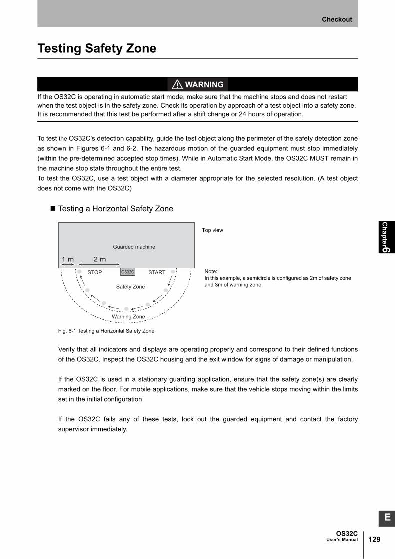
129OS32C
User’s Manual
Ch
ap
ter6
Checkout
E
Testing Safety Zone
If the OS32C is operating in automatic start mode, make sure that the machine stops and does not restart when the test object is in the safety zone. Check its operation by approach of a test object into a safety zone. It is recommended that this test be performed after a shift change or 24 hours of operation.
To test the OS32C’s detection capability, guide the test object along the perimeter of the safety detection zone
as shown in Figures 6-1 and 6-2. The hazardous motion of the guarded equipment must stop immediately
(within the pre-determined accepted stop times). While in Automatic Start Mode, the OS32C MUST remain in
the machine stop state throughout the entire test.
To test the OS32C, use a test object with a diameter appropriate for the selected resolution. (A test object
does not come with the OS32C)
Testing a Horizontal Safety Zone
Fig. 6-1 Testing a Horizontal Safety Zone
Verify that all indicators and displays are operating properly and correspond to their defined functions
of the OS32C. Inspect the OS32C housing and the exit window for signs of damage or manipulation.
If the OS32C is used in a stationary guarding application, ensure that the safety zone(s) are clearly
marked on the floor. For mobile applications, make sure that the vehicle stops moving within the limits
set in the initial configuration.
If the OS32C fails any of these tests, lock out the guarded equipment and contact the factory
supervisor immediately.
Guarded machine
OS32C
Safety Zone
STOP START
Warning Zone
1 m 2 m
Note:In this example, a semicircle is configured as 2m of safety zoneand 3m of warning zone.
Top view

130
Ch
ap
ter6
OS32CUser’s Manual
Checkout
Testing a Vertical Safety Zone
Fig. 6-2 Testing a vertical safety zone
Verify that all indicators and displays are operating properly and correspond to their defined functions
of the OS32C. Inspect the OS32C housing and the exit window for signs of damage or manipulation.
If the OS32C is used in a hand/arm guarding application, ensure that the OS32C resolution is
configured for 30mm or 40mm only.
If the OS32C fails this test, lock out the guarded equipment and contact the factory supervisor
immediately.
Front View

131OS32C
User’s Manual
Ch
ap
ter6
Checkout
E
Detection Capability
The OS32C has an adjustable minimum object resolution of 30mm, 40mm, 50mm, or 70mm. Depending on
the configured minimum object resolution selected by the user, this means the OS32C will detect an object
(30/40/50/70)mm or larger in diameter that is completely within the field of view. The figure below shows an
example for when the minimum object resolution is configured for 70mm.
Fig. 6-3 Field of View
The maximum radius of the safety zone will depend on the minimum object resolution selected:
Table 6-1 Minimum object resolution and maximum safety zone radius
Zone of Limited Detection CapabilityThe OS32C has a Zone of Limited Detection Capability that extends 5cm from the front window, or up
to 9 cm from the center of rotation. Objects with very low reflectance in this area may not be detected.
Fig. 6-4 Limited Detection Zone
The installer is responsible for assessing the risk and to ensure that the zone of limited detection does not create a safety hazard. If a hazard exists additional countermeasure must be taken, this may require additional guarding measures.
Minimum object resolution (mm)Maximum safety zone radius
(3m range version)(m)Maximum safety zone radius
(4m range version)(m)
30 1.75 1.75
40 2.5 2.5
50 3.0 3.4
70 3.0 4.0
70mm object detected
OS32C
Field of View
70mm objectdetected
70mm objectnot detected
Safety Zone
9 cm
Side View
5 cm
9 cm
Center ofRotation
Top View

132
Ch
ap
ter6
OS32CUser’s Manual
Checkout

Ch
apter7
133OS32C
User’s Manual
E
Chapter7 Appendix
Troubleshooting 134
Troubleshooting 134
OS32C Status Check 137
Additional Error due to Reflective Background 139
Conditions of Background Influence 139
Using Other Safety Device in Combination 141
Sensor and I/O Block Replacement 142
Scan Window Replacement Procedure 143
Window Replacement Procedure 143
OS32C Maintenance 145
Warning Zone Object Resolution 146
Additional Zone Set Switching Strategies 147
Glossary 151
Accessories 153
Checkout and Test Procedure Log 154
Declaration of Conformity 155
Revision History 156
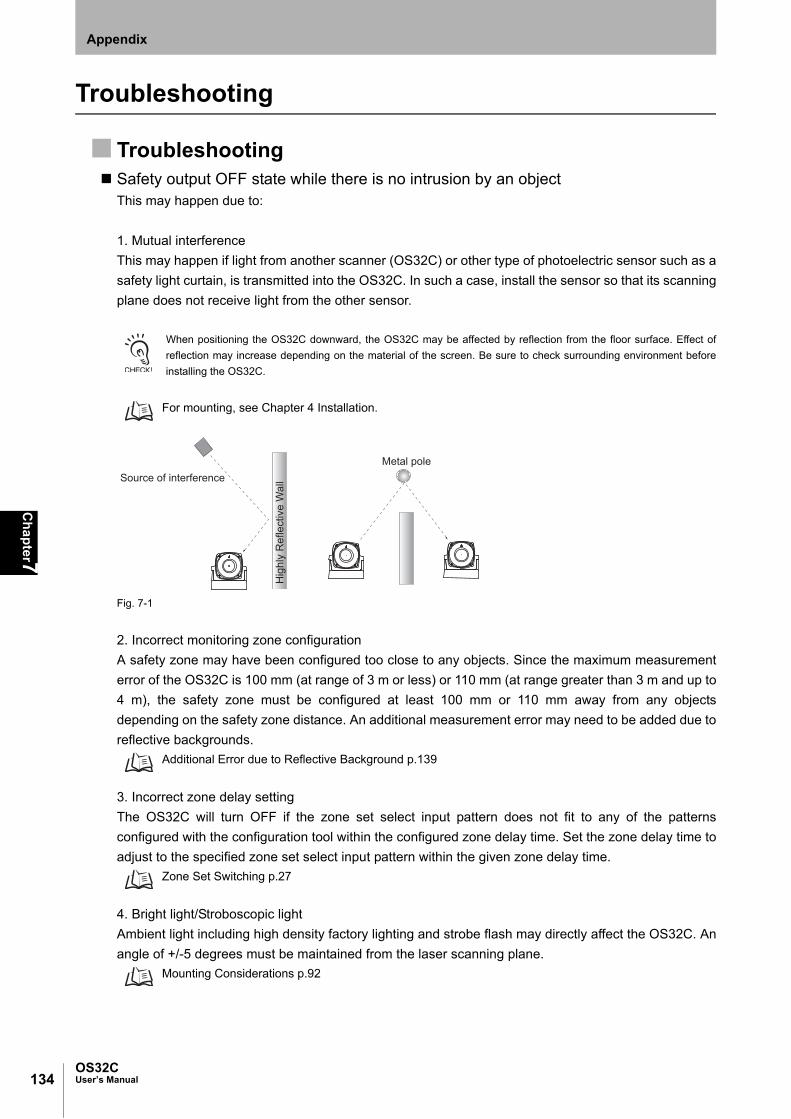
134
Ch
apter7
OS32CUser’s Manual
Appendix
Troubleshooting
Troubleshooting Safety output OFF state while there is no intrusion by an object
This may happen due to:
1. Mutual interference
This may happen if light from another scanner (OS32C) or other type of photoelectric sensor such as a
safety light curtain, is transmitted into the OS32C. In such a case, install the sensor so that its scanning
plane does not receive light from the other sensor.
When positioning the OS32C downward, the OS32C may be affected by reflection from the floor surface. Effect of
reflection may increase depending on the material of the screen. Be sure to check surrounding environment before
installing the OS32C.
For mounting, see Chapter 4 Installation.
Fig. 7-1
2. Incorrect monitoring zone configuration
A safety zone may have been configured too close to any objects. Since the maximum measurement
error of the OS32C is 100 mm (at range of 3 m or less) or 110 mm (at range greater than 3 m and up to
4 m), the safety zone must be configured at least 100 mm or 110 mm away from any objects
depending on the safety zone distance. An additional measurement error may need to be added due to
reflective backgrounds.
Additional Error due to Reflective Background p.139
3. Incorrect zone delay setting
The OS32C will turn OFF if the zone set select input pattern does not fit to any of the patterns
configured with the configuration tool within the configured zone delay time. Set the zone delay time to
adjust to the specified zone set select input pattern within the given zone delay time.
Zone Set Switching p.27
4. Bright light/Stroboscopic light
Ambient light including high density factory lighting and strobe flash may directly affect the OS32C. An
angle of +/-5 degrees must be maintained from the laser scanning plane.
Mounting Considerations p.92
Hig
hly
Ref
lect
ive
Wal
lSource of interferenceMetal pole

135OS32C
User’s Manual
Ch
apter7
Appendix
E
5. Dirty environment
Dirty environment, for instance fog, smoke, steam or other small flying particles may cause the
incorrect switching of a Machine Stop state. The influence of the incorrect switching may be decreased
if the response time can be increased. To avoid the operation failure, keep the monitoring area clean.
The scanner has higher immunity to small particles or dust when configured for 50mm and 70mm object resolutions.
Installation p.91
If the response time is changed, re-calculation of the safety distance is required. This may
require re-configuration of the safety zones or re-installation of the OS32C. If the safety
distance is not appropriate for the application, the machine may not stop before the hazardous
area is reached, resulting in severe injuries.
6. Dirty window
Check if the scan window or dust detection surface (on the base of the window). If the status/diagnostic
display shows error code 80, the scan window should be cleaned with a soft cloth.
Slow response of the safety output turning ONThis may happen due to unexpected turning OFF of the safety outputs for the reasons described
above.
Constant Safety Output OFF1. Dirty window
If the status/diagnostic display shows error code 80, and if the error cannot be reset by cleaning of the
scan window, replacement of the scan window may be needed.
Do not put any sealant on the optics cover. If the scan window of the OS32C is replaced, a window calibration needs
to be performed by the configuration software. See Chapter 3 Window Calibration.
2. Safety zone layout change
Verify that no objects are intruding in the configured safety zone. If the OS32C is detecting something,
the intrusion indicator will turn ON. The configuration software can also be used to monitor the
scanning information of the OS32C.
If the configuration software cannot receive configuration from the OS32C
1. The communication cable is not properly connected.
Check connections of the communication cable and the ethernet cable.
2. An OS32C has been set to a fixed IP address and the user loses the address. The user will need to
set both the PC and the scanner to DHCP mode so that they can communicate with each other, before
the user can set the scanner to a new fixed IP address.
See page 42. to force the scanner into DHCP mode.

136
Ch
apter7
OS32CUser’s Manual
Appendix
Configuration Tool was unable to find sensors on the network(1) Check power and ethernet cables
(2) Check the IP address settings of the PC and the scanner. Make sure both are on the same
network.
See Chapter 3: Connecting the PC and the OS32C
Communication Time Out(1) Check power and ethernet cables.
(2) Check the IP address settings of the PC and the scanner. Make sure both are on the same
network.
See Chapter 3: Connecting the PC and the OS32C

137OS32C
User’s Manual
Ch
apter7
Appendix
E
OS32C Status CheckThe OS32C has the status/diagnostic display on the front, which indicates configuration/error status of
the OS32C.
Diagnostic Codes
StatusDiagnostic
CodeDescription Corrective Action
Normal Operation 88 Power up indication -
-- Normal operation (guarded machine stop)
-
- - blinking at a slow rate
Standby mode (guarded machine stop). The rate of blinking depends on the mode.
-
01 Interlock state (waiting for start input) -
02 Configuration mode (guarded machine stop)
-
80 Window contamination indication (guarded machine stop)
The window is dirty or scratched, clean or replace as necessary
83 Window condensation indication (guarded machine stop)
Condensation is detected in the window, wait for unit to warm up
84 Blinded beams indication (guarded machine stop)
Check for mutual interference with another scanner (see mounting considerations on the user manual), nearby retro-reflectors or strong interfering light sources. Mounting Considerations p.92
70 Incorrect number of active zone set select inputs (guarded machine stop)
Check zone set select input wiring, zone configuration selection, zone set select input switching time and zone delay configuration
71 Invalid or undefined zone set select input combination but correct number of active zone set select inputs (guarded machine stop)
Check zone set select input wiring, zone configuration selection, zone set select input switching time and zone delay configuration
Table 2-5 -
Safety output fault 30 Safety output fault Check output connection and wiring.
32 Safety output A is short-circuited to 24V
33 Safety output B is short-circuited to 24V
34 Safety output A is short-circuited to 0V
35 Safety output B is short-circuited to 0V
External device monitoring fault
40 EDM (external device monitoring) fault Check output external device monitoring connection and wiring.
41 External device monitoring fault before OSSD turning ON
Check the NC-contact status of the external device is changing state before the OSSDs turning ON.
42 External device monitoring fault after OSSD turning ON
Check the NC-contact status of the external device is changing state after the OSSDs turning ON.
43 External device monitoring fault during OS32C power on
Check the OS32Cs output configuration,connections and wiring.

138
Ch
apter7
OS32CUser’s Manual
Appendix
Table 7-1 Diagnostic Code References
Other fault 50 General fault - caused by internal problem or extreme environmental condition
Check environment for excessive vibration, shock or electrical noise; check that the window assembly is undamaged and securely attached. Or consult factory.
51 Mutual interference Check for mutual interference with another scanner (see mounting considerations on the user manual), nearby retro reflectors (<1m) or strong interfering light sources.
Mounting Considerations p.92
52 General fault - caused by internal problem or extreme environmental condition
Check the environment for electrical noise sources or interfering light sources. Or consult factory.
53
54
55 Internal fault - unused Consult factory.
56 General fault - caused by internal problem or extreme environmental condition
Check the environment for electrical noise sources or interfering light sources. Or consult factory.
57
58
59 Check environment for excessive vibration or shock.
60 Invalid configuration in unit Double check current configuration or reset the scanner back to manufacture default configuration.
Reset to Default Configuration p.88
72 Incorrect number of active zone set select inputs (hard fault code after diagnostic code 70 above persists for more than 10 minutes)
Check zone set select input wiring and zone configuration selection.
73 Invalid or undefined zone set select input combination, but correct number of active zone set select inputs. (hard fault code after diagnostic code 71 persists for more than 10 minutes)
Check zone set select input wiring and zone configuration selection.
74 Standby input or zone set select inputs voltage too high
Check zone set select inputs or standby input wired at more than system power (24 VDC).
75 Scanner chassis connected to power (24 VDC)
Scanner chassis should be grounded to 0 VDC
81 Window condensation (fault code after diagnostic code 83 persists for more than 30 minutes)
Cycle power on unit and allow to run with diagnostic code 83, internal generated heat will reduce condensation. (if possible reduce moisture in the environment)
82 Window not detected or entire dust detection surface is dirty or blocked.
Check that the window is properly mounted and clean the dust detection surface.
90 Internal temperature fault The scanner internal temperature exceeds the operating limit. Add more ventilation.
StatusDiagnostic
CodeDescription Corrective Action

139OS32C
User’s Manual
Ch
apter7
Appendix
E
Additional Error due to Reflective Background
An additional measurement error may need to be added due to reflective backgrounds. See Specifications of additional Errors by Background.
Conditions of Background InfluenceThe OS32C's measurement precision can be affected by the background reflection of an object.
(1) High-reflective background material or object is present in the scanning plane and within 1.2m
beyond the safety zone.
(e.g. acryl panel, stainless steel, reflective tape, mirror)
(2) Low-reflective background material or object is present in the scanning plane and within 1.2m
beyond the safety zone.
(e.g. paint-finished equipment)
If any of the conditions listed above apply to your application, an additional error factor (Z2) should be
added to the calculated safety zone size.
M = Result of safety zone calculation from safety distance
Z = Additional safety factors (maximum measurement error), Z = Z1+ Z2
Z1 = The OS32C’s maximum measurement error (100 mm at range of 3 m or less and 110 mm at
range of greater than 3 m)
Z2 = Additional Error by Reflective Background
Fig. 7-2
Barrier
Machine table
Danger zone
Top View
Distance to the background beyond the safety zone
Reflective background or object
Safety zone distance M
Additional error by reflective background Z2
Safety zone to be configured by the configuration software
The OS32C's maximum measurement error Z 1 (100 mm at range of 3 m or less and 110 mm at range of greater than 3 m)
See Table 7-2

140
Ch
apter7
OS32CUser’s Manual
Appendix
Use the following steps to calculate the additional error Z2 from the safety zone distance M. Take
OS32C's measurement error Z1 and the additional error Z2 into account to setup safety zone with the
configuration software.
Procedure1. Use Table 7-2 to calculate the additional error Z2 for the safety zone distance M.
2. Measure a distance to a reflective background or object assuming M+Z1+Z2 as the edge of the safety
zone.
3. If the dimension above satisfies the condition (1) or (2), add Z1 and Z2 to the value for the safety zone
range. If neither condition is satisfied, add Z1 without adding Z2.
Table 7-2 Additional error by background influence

141OS32C
User’s Manual
Ch
apter7
Appendix
E
Using Other Safety Device in CombinationIf the OS32C is used for presence detection only, instead of intrusion detection, it is not necessary to
take the additional error Z2 into account. Figures 7-3 and 7-4 show examples using OS32C for
presence detection only.
Configure the safety zone with a distance of at least 100 mm or 110 mm (see page 94), taking only OS32C's
measurement error Z1 = 100 mm (at range of 3 m or less) or 110 mm (at range greater than 3 m and up to 4 m) into
account.
Fig. 7-3 Installing Safety Light Curtain on Entra7-3nce
Fig. 7-4 Installing Door on Entrance
Required distance from the wall Z1 = 100 mm or 110 mm
The OS32C's maximum measurement error Z1
Safety light curtain (e.g. F3SJ, MS4800)
Reflective background or object
Danger zone
Actual configured zone
The OS32C's maximum measurement error Z1
Reflective background or object
Reflective background or object
Danger zoneSafety door switch
Door
Actual configured zone
Required distance from the wall Z1 = 100 mm or 110 mm

142
Ch
apter7
OS32CUser’s Manual
Appendix
Sensor and I/O Block Replacement
Take precautions to prevent dirt, dust or debris from entering the sensor and I/O block connectors. It isrecommended that this be done on a clean workstation as contaminants may degrade the performance of theOS32C.
When either the sensor block or the I/O block is replaced, the Checkout and Test Procedure on page 125
must be performed.
Fig. 7-5 Sensor Block Replacement
Required Tool: 3mm Allen wrench
1. Remove power from the OS32C.
2. Remove the four screws and washers that secure the sensor block to the I/O block.
3. Replace the old sensor block or I/O block with the new one.
4. Replace the four screws with flat and lock washers in an alternating patterns. It is recommended that
the screws be tightened to a torque of 1.5 - 2.0 N•m (13.28 - 17.1 lb-in).
WASHER, LOCK(x4)
SCREW(x4)(M4 x 20) WASHER, FLAT(x4)
I/O BLOCK, ASSY
SENSOR HEAD, ASSY
(1)
(3)(2)
(4)

143OS32C
User’s Manual
Ch
apter7
Appendix
E
Scan Window Replacement Procedure
Window Replacement Procedure
Do not modify the main unit of the OS32C. Do not replace or fix any component of the OS32C other than the ones specified in this manual. Doing so may result in a failure of the safety functions.
If there is any damage to the scan window such as a crack, replace it as soon as possible. Otherwise it may result in a failure of the protective mechanism. Take preventive measures when performing replacement work so that dust does not enter the OS32C.
Always detach all cables from the OS32C before replacing the scan window. Otherwise the motor may start rotating, resulting in injuries.
The window replacement procedure must only be performed by qualified personnel in a clean environment at ambient temperature (5 to 35°C) to prevent the internal optical surface from contamination. Make sure the inside and the outside of the replacement window is clean and free from scratch, dust, and finger print.
Adhesion of dust to the scan window may cause a false operation. The OS32C will require periodic cleaning of the scan window and dust detection surface.
Window Replacement Kit OS32C-WIN-KTKit contents
•Scan Window 1
•Gasket (pre-installed in window) 1
•Screw for window (M3) 4
•Flat Washer 4
NOTE: The window replacement kit OS32C-WIN-KT can be used on any sensor block.
Required Tool: 2mm Allen wrench
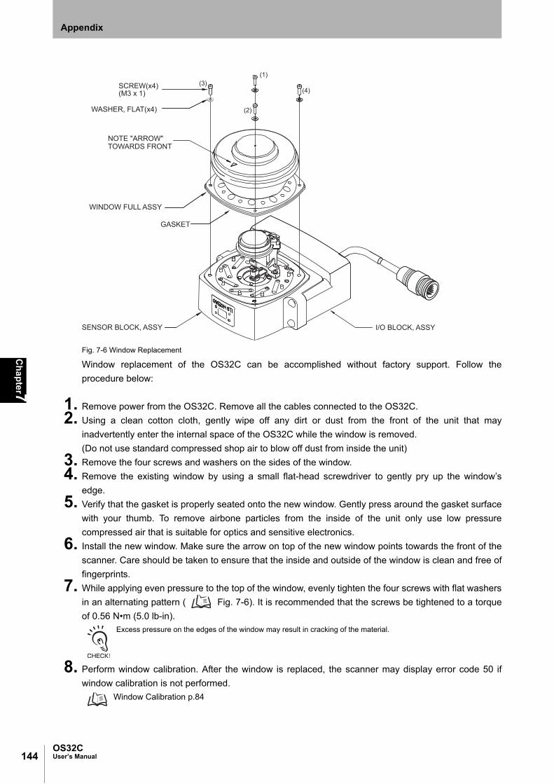
144
Ch
apter7
OS32CUser’s Manual
Appendix
Fig. 7-6 Window Replacement
Window replacement of the OS32C can be accomplished without factory support. Follow the
procedure below:
1. Remove power from the OS32C. Remove all the cables connected to the OS32C.
2. Using a clean cotton cloth, gently wipe off any dirt or dust from the front of the unit that may
inadvertently enter the internal space of the OS32C while the window is removed.
(Do not use standard compressed shop air to blow off dust from inside the unit)
3. Remove the four screws and washers on the sides of the window.
4. Remove the existing window by using a small flat-head screwdriver to gently pry up the window’s
edge.
5. Verify that the gasket is properly seated onto the new window. Gently press around the gasket surface
with your thumb. To remove airbone particles from the inside of the unit only use low pressure
compressed air that is suitable for optics and sensitive electronics.
6. Install the new window. Make sure the arrow on top of the new window points towards the front of the
scanner. Care should be taken to ensure that the inside and outside of the window is clean and free of
fingerprints.
7. While applying even pressure to the top of the window, evenly tighten the four screws with flat washers
in an alternating pattern ( Fig. 7-6). It is recommended that the screws be tightened to a torque
of 0.56 N•m (5.0 lb-in).Excess pressure on the edges of the window may result in cracking of the material.
8. Perform window calibration. After the window is replaced, the scanner may display error code 50 if
window calibration is not performed.
Window Calibration p.84
SENSOR BLOCK, ASSY
WASHER, FLAT(x4)
WINDOW FULL ASSY
I/O BLOCK, ASSY
NOTE "ARROW"TOWARDS FRONT
SCREW(x4)(M3 x 1)
GASKET
(1)
(2)
(3)(4)
145OS32C
User’s Manual
Ch
apter7
Appendix
E
OS32C MaintenanceThe OS32C will require periodic cleaning of the scan window and dust detection surface on the base of
the window. The interval of the cleanings will depend on the environment in which the OS32C is used.
It is recommended that the window be cleaned using a common glass/plastic cleaner. The window
should be sprayed and wiped down with a soft cloth to prevent damage to the surface.

146
Ch
apter7
OS32CUser’s Manual
Appendix
Warning Zone Object Resolution
The user can configure up to two warning zones for each zone set with the OS32C. The warning zone should
be configured to be larger than the safety zone so that it can send a warning signal before the intrusion
approaches into the safety zone.
The OS32C warning zone object resolution is determined by the nominal object resolution and the reflectance
value. It varies depending on the distance from the scanner.
Fig. 7-7 Warning zone object resolution

147OS32C
User’s Manual
Ch
apter7
Appendix
E
Additional Zone Set Switching Strategies
The following information provides additional strategies to specify protection zones that guarantee protection
of zone set A when zone set may switch before monitoring of zone set A is no longer required when switching
from zone set A to zone set B (tEndZoneA). These examples focus on the dangerous area that exists during zone
set transitions, limiting the extended protection zone Zextra to only the areas that need it as opposed to a
general extension as described in section 2.
The following diagram uses the same example zone set layout as in the example in section 2, Fig. 2-14.
Based on transition related timing parameters previously discussed, this diagram identifies the actual
remaining danger area during zone set switching (during Textend).
The danger area identified in this diagram is only for example, the actual shape of the danger area will vary based on the
installation.
Fig. 7-8 Danger area during zone set switching
There are 3 options for ensuring the Danger Area is adequately guarded during the transition, described in the
following examples.
Zone set B
Zone set A
Danger Area during zone set switching
OS32C
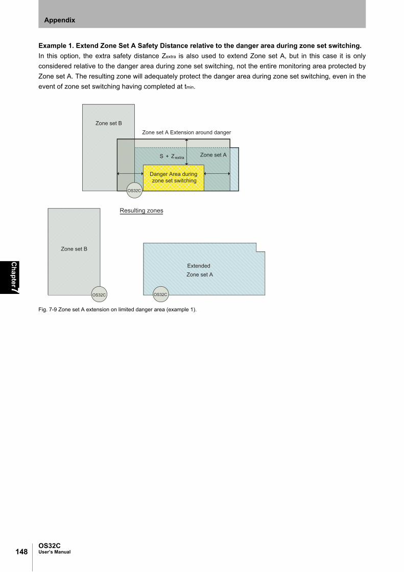
148
Ch
apter7
OS32CUser’s Manual
Appendix
Example 1. Extend Zone Set A Safety Distance relative to the danger area during zone set switching.
In this option, the extra safety distance Zextra is also used to extend Zone set A, but in this case it is only
considered relative to the danger area during zone set switching, not the entire monitoring area protected by
Zone set A. The resulting zone will adequately protect the danger area during zone set switching, even in the
event of zone set switching having completed at tmin.
Fig. 7-9 Zone set A extension on limited danger area (example 1).
Zone set A Extension around danger
Zone set B
Zone set A
Danger Area during zone set switching
S + Zextra
Zone set B
ExtendedZone set A
Resulting zones
OS32C OS32C
OS32C

149OS32C
User’s Manual
Ch
apter7
Appendix
E
Example 2. Extend Zone Set B to protect the danger area during zone set switching in Zone Set A.
In this option, no change is made to Zone set A. Instead, the definition of Zone set B is extended to protect the
danger area during zone set switching in zone set A. For this expansion, only the normal safety distance to
define zone set A should be considered. This solution may not be practical if Zone set A and Zone set B are
basically independent, but in cases where Zone set A and Zone set B naturally overlap and/or the danger is
due to a device that simply moves from Zone set A to Zone set B, this option may be used.
Fig. 7-10 Zone set B extension on limited danger area (example 2).
Zone set B Extension around dangerZone set B
Zone set A
Danger Area during zone set switching
S
OS32C
ExtendedZone set B
Resulting zones
Zone set A
OS32C OS32C
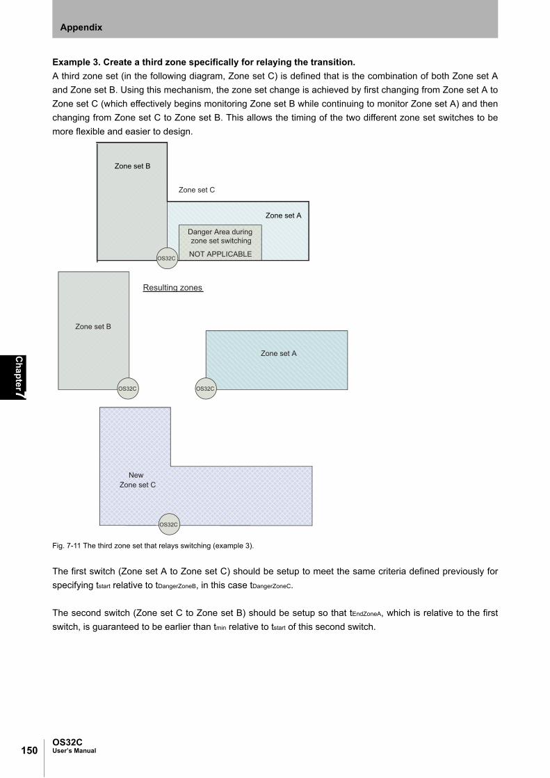
150
Ch
apter7
OS32CUser’s Manual
Appendix
Example 3. Create a third zone specifically for relaying the transition.
A third zone set (in the following diagram, Zone set C) is defined that is the combination of both Zone set A
and Zone set B. Using this mechanism, the zone set change is achieved by first changing from Zone set A to
Zone set C (which effectively begins monitoring Zone set B while continuing to monitor Zone set A) and then
changing from Zone set C to Zone set B. This allows the timing of the two different zone set switches to be
more flexible and easier to design.
Fig. 7-11 The third zone set that relays switching (example 3).
The first switch (Zone set A to Zone set C) should be setup to meet the same criteria defined previously for
specifying tstart relative to tDangerZoneB, in this case tDangerZoneC.
The second switch (Zone set C to Zone set B) should be setup so that tEndZoneA, which is relative to the first
switch, is guaranteed to be earlier than tmin relative to tstart of this second switch.
Zone set B
Zone set A
Danger Area during zone set switching
NOT APPLICABLE
Zone set C
OS32C
New Zone set C
Resulting zones
Zone set A
Zone set B
OS32C OS32C
OS32C

151OS32C
User’s Manual
Ch
apter7
Appendix
E
Glossary
Term Definition
Automatic Start An object entering the safety zone turns the OSSDs OFF. Once the safety zone is clear, the sensor will automatically enter the safety output ON state.
Auxiliary Output This is a non-safety output. It may be configured to provide safety output information or lockout information.
Edit Monitoring Zones When enabled the edit zones mode will allow the current configurations of the safety and warning zones to be modified. The monitoring zones are graphically displayed for editing. This feature can only be used with an access log-on level of supervisor user or higher.
External Device Monitoring The function to detect a fault, such as the welding of the NC-contacts of the machine's primary control element.
Interlock OSSD OFF status is maintained until safety is ensured and the start input is applied.
Lockout A failure is detected and the guarded machine is stopped. The OS32C system will remain in the lockout state until the problem is corrected and a start input is applied.
Maintenance Access Level This access level allows a user to edit only the non-safety parameters of the OS32C. A password is required to log on to the OS32C with this access level.
Minimum Object Resolution The minimum width of an object that will be detected by the scanner. This is a user configurable setting with resolutions of 30mm, 40mm, 50mm, and 70mm. The default setting is 70mm.
Monitor Mode In this mode, the continuously measured data from the OS32C is displayed on the screen in real-time.
Monitoring Zone The cumulative area of the safety and 2 warning zones.
Monitoring Zone Set There are 70 selections for this property. A user can select a zone set in the zone set configuration window.
Non-Safety Critical Parameters These are settings that are not related to the safe installation of the OS32C: Auxiliary output, warning output, restart delay, and standby mode.
Offline Mode A user can create, edit, and save a configuration to a PC without connecting to the OS32C. The loading and editing of existing configurations on the PC can be done offline as well.
Operator Access Level This access level cannot change the OS32C settings. Only verification and monitoring of the existing configuration information is available. Password input is not required.
OSSD (Output Signal Switching Device)
This provides ON output when no object is interrupting the sensor in the safety zone. It is used for safety applications.
Pollution Tolerance Mode (PTM) This function enables a filter that allows the scanner to distinguish between more than one detected reflections caused by reflective pollution particles.
Reference Boundary Monitoring When activated, the scanner will monitor the boundary of a given detection zone (safety or warning). The detection zone will be considered violated if the boundary range requirements are not within a certain tolerance.
Response Time The maximum time between the actuation of the sensor function and the switching of the safety outputs of the OS32C. The response time ranges from 80ms (2 scans) to 680ms (17 scans), in increments of 40ms.
Safety Critical Parameters These are the settings that configure the safe installation of the OS32C: External device monitoring, response time, operating mode, zone set selection, zone set select input combos, zone transition delay, minimum object resolution, and reference boundary monitoring.
Safety Zone A user-defined protection area to which intrusion of an object stops the guarded machine. When an object enters this area, the safety outputs of OS32C turns OFF within a predefined response time. This zone is a safety-critical property.
Sculpting Within a scanning range of OS32C, a position where closest to OS32C can be automatically configured as a zone. A distance subtracting 100mm from that to an object is configured.
Start If start interlock or restart interlock is configured, applying the start input releases the interlock state.It can be also used to release lockout.
Start Interlock After OS32C is started, the interlock state is maintained. Once the interlock is released by the start input, an object entering the safety zone shall turn OSSD OFF. Once the safety zone is clear, the sensor will automatically enter the safety output ON state.
Start/Restart Interlock After the OS32C is started, the interlock state is maintained. After the interlock is released by the start input, an object entering the safety zone shall turn OSSD OFF and the interlock state is maintained.

152
Ch
apter7
OS32CUser’s Manual
Appendix
Supervisor Access Level To log on to the OS32C with this access level, a password is required. This access level allows a user to edit OS32C configuration information and send it to the OS32C.
Warning Zone When an object enters the warning zone, warning zone infringed will be reported. This zone allows for a larger scanning area than the safety zone and can be used to activate a warning function. This zone is a non-safety-critical property.
Window Contamination Warning This output can be assigned to the warning output and will turn ON when contamination of the scan window reaches a certain level.
Window Calibration This is required for replacement of the window.Window calibration resets the threshold value of window transmittance.This threshold value is used for Window contamination warning.
Zone Set Select Up to 70 zone sets can be switched according to the wiring for zone set selection. Refer to "Zone Set Selection" on page 19.
Term Definition

153OS32C
User’s Manual
Ch
apter7
Appendix
E
Accessories
*1 When using a mounting stand, use an OS32C with side location cable entry. The OS32C with back location
cable entry cannot be mounted. Use with XY axis rotation bracket (OS32C-BKT2).
*2 Use this when mounting a bracket to the mounting stand.
Description Model
Complete OS32C Systems
OS32C laser scanner with 3m range and back location cable entry OS32C-BP
OS32C laser scanner with 4m range and back location cable entry OS32C-BP-4M
OS32C laser scanner with 3m range, EtherNet/IP and back location cable entry OS32C-BP-DM
OS32C laser scanner with 4m range, EtherNet/IP and back location cable entry OS32C-BP-DM-4M
OS32C laser scanner with 3m range and side location cable entry OS32C-SP1
OS32C laser scanner with 4m range and side location cable entry OS32C-SP1-4M
OS32C laser scanner with 3m range, EtherNet/IP and side location cable entry OS32C-SP1-DM
OS32C laser scanner with 4m range, EtherNet/IP and side location cable entry OS32C-SP1-DM-4M
Spare OS32C Sensor Block
Spare sensor block with 3m range, without I/O block OS32C-SN
Spare sensor block with 4m range, without I/O block OS32C-SN-4M
Spare sensor block with 3m range, EtherNet/IP, without I/O block OS32C-SN-DM
Spare sensor block with 4m range, EtherNet/IP, without I/O block OS32C-SN-DM-4M
Spare OS32C I/O Blocks
Spare I/O block with cable access from the back OS32C-CBBP
Spare I/O block with cable access from the left side OS32C-CBSP1
Power Cables
3m cable for power and I/O OS32C-CBL-03M
10m cable for power and I/O OS32C-CBL-10M
20m cable for power and I/O OS32C-CBL-20M
30m cable for power and I/O OS32C-CBL-30M
Ethernet Cables
2m cable for scanner configuration OS32C-ECBL-02M
5m cable for scanner configuration OS32C-ECBL-05M
15m cable for scanner configuration OS32C-ECBL-15M
Mounting Brackets
Bottom/Side Mounting Bracket OS32C-BKT1
XY Axis Rotation Bracket (must be used with OS32C-BKT1) OS32C-BKT2
Simple mounting bracket OS32C-BKT3
Protective cover for window OS32C-BKT4
OS32C mounting stand (for use with OS32C-SP1) *1 OS32C-MT
OS32C hardware kit to mount BKT1, BKT2, BKT3 to OS32C-MT *2 OS32C-HDT
Miscellaneous
Window replacement kit OS32C-WIN-KT
Printed user manual English(paper) OS32C-MANUAL-EN
Printed user manual Japanese (paper) OS32C-MANUAL-JP
Spare CD (Configuration Tool + user manual) OS32C-CD
Window cleaning kit WIN-CLN-KT

154
Ch
apter7
OS32CUser’s Manual
Appendix
Checkout and Test Procedure Log
The following test procedure must be performed by qualified personnel:
•during initial OS32C system installation
•after any maintenance, adjustments or modifications to the OS32C or the machine it is guarding
•at least every three months or more frequently depending on machine usage and employer guidelines
Testing ensures that the OS32C system and machine control system work together to properly stop the
machine. Failure to properly test the equipment could result in serious injury to personnel.
If the safety system or the machine fails any of these tests, do not run the machine. Immediately tag or lock out the machine to prevent its use and notify the appropriate supervisor.
Machine Identification: Date:
Technician Signature: Checksum (if applicable):
Item Condition Comments
1. Disable the guarded machine. Apply power to the OS32C system. PassFail
2. Verify that the guarded machine is suitable for use with the OS32C system. See “Introduction” for more information
PassFail
3. Visually inspect the machine to ensure that all access to the danger point is through the OS32C safety zone. If access to any danger point is possible without being detected by OS32C, additional protective measures must be taken such as barriers. Verify that all other guarding devices and barriers are installed and operating properly.
PassFail
4. Verify that the correct minimum object resolution has been selected in accordance with the application type.
PassFail
5. Verify that the maximum safety zone distance of the OS32C system is equal to or greater than the calculated safety zone distance from the danger point. Make sure that the operator cannot stand between the safety zone and the danger zone. See Chapter 4 for calculation of the safety distance.
PassFail
6. Verify that the scanner can only be reset from a position outside and with a view of the monitoring zone.
PassFail
7. Check for signs of external damage to the OS32C system, the guarded machine, the electrical cables and wiring.
PassFail
8. Verify that the connections between the control system of the guarded machine and the OS32C are correct.
PassFail
9. Start the machine. While the machine is in motion, intrude into the safety zone with the test object. The machine should stop immediately. Move the test object inside the perimeter of the safety zone. The machine should remain stopped.Caution: Never insert the test object into the dangerous parts of the machine.
PassFail
10. Verify that the machine braking system is working properly. If the machine does not stop fast enough, adjust the braking system or increase the safety zone distance.
PassFail
11. Record the results of this procedure in the machine log. PassFail

155OS32C
User’s Manual
Ch
apter7
Appendix
E
Declaration of Conformity
OMRON SCIENTIFIC TECHNOLOGIES INCORPORATED EC Declaration of Conformity
OMRON Scientific Technologies Incorporated (at 6550 Dumbarton Circle, Fremont, CA 94555-3605, U.S.A.), hereby declares that the following series manufactured products listed below conform with the relevant Essential Health and Safety Requirements (EHSRs) of the European Machinery Directive (2006/42/EC), with the relevant requirements of the Low Voltage Directive (2006/95/EC), with the essential protection requirements of the Electromagnetic Compatibility (EMC) Directive (2004/108/EC) and with the RoHS Directive (2011/65/EC) - the restriction of the use of certain hazardous substances in electrical and electronic equipment.
OS32C Series The OS32C Series Laser Scannner is an Electro Sensitive Protective Equipment (ESPE); Active Optoelectric Protective Device responsive to Diffuse Reflections (AOPDDR), Type 3, designed to detect persons as part of a safety related system. The OS32C Series products have been type-examined per the
EC Type-Examination Certificate
issued by notified body TUV Rheinland Industrie Service GmbH, Alboinstr. 56, 12103 Berlin/Germany, Certification Body for Machinery (NB No. 0035). The following Standards were used to form the basis for the requirements and tests:
IEC 61496-3:2008 - Safety of machinery – Electro Sensitive Protective Equipment, Part 3: Particular requirements for Active Optoelectric Protective Device responsive to Diffuse Reflections (AOPDDR). IEC 61496-1:2012 - Safety of machinery – Electro Sensitive Protective Equipment, Part 1: General requirements and tests. EN 62061:2005+AC:2010+A1:2013 – Safety of machinery. Functional safety of safety-related electrical, electronic and programmable electronic control systems. EN ISO 13849-1:2008+ AC:2009 - Safety of machinery – Safety-related parts of control systems, Part 1: General principle for design. EN 61508, Parts 1 – 7:2010 - Functional Safety Of Electrical/Electronic/Programmable electronic Safety-Related
Systems. EN 50178:1997: Electronic equipment for use in power installations. EN 60204-1:2006+A1:2009+AC:2010 (in extracts): Safety of machinery – Electrical equipment of machines, Part 1: General requirements. ANSI B11.19:2010, ANSI/RIA R15.06:2012, NFPA 79:2012, Code of Federal Regulations CFR29:1990.
Martin D. Krikorian Representative in EU: J.J.P.W. Vogelaar Quality Director European Quality & Environment Operations Manager (Authorized Signer of Declarations of Conformity) Omron Europe B.V OMRON Scientific Technologies, Inc. Zilverenberg 2, 5234 GM, 's-Hertogenbosch, The Netherlands

156
Introduction
OS32CUser’s Manual
Appendix
Revision History
A manual revision code appears as a suffix to the manual number at the bottom of the front and back covers
of this manual.
Revision code Date Revised contents
01 April 2010 First edition
02 November 2010 Minor corrections
03 March 2011
- Support for configurable minimum object resolutions- Copy & paste zones and zone sets- Record system monitoring- Playback system monitoring- Support for Windows 7- Display configuration file name in config tool header- Additional zone shapes available: 180° semi-circle, 180° rectangle, and 180° polygon- Support for inverting 7-segment display- Troubleshooting tips in fault log- Config tool support for switching between default OS32C configuration and the user's current working configuration
- Configuration checksum
04 May 2011 Minor corrections
05 November 2011- Added zone of limited detection- Minor corrections
06 December 2012
- Support for EtherNet/IP and Measurement Data features- Added Maintenance access level- Added non-safety checksum- Added zone coordinate import/export function
07 February 2013 Minor corrections
08 October 2013- Added multiple zone coordinate import/export function- Added multiple languages: French, German, Italian, Spanish- Added screen orientation rotation
09 April 2014
- Added 4 meter safety range and 15 meter warning range information- Added Pollution Tolerance modes (PTM) information- Added variable response time settings information- Added status information during monitor mode- Added warning messages for window calibration and window replacement procedure - Added caution message for OS32C mounting- Added warning zone object resolution
10 March 2015- Added instruction to reset the scanner back to manufacture default configuration- Minor correction
Revision code
Manual No. Z296-E1-10

Terms and Conditions of Sale1. Offer; Acceptance. These terms and conditions (these "Terms") are deemed
part of all quotes, agreements, purchase orders, acknowledgments, price lists,catalogs, manuals, brochures and other documents, whether electronic or inwriting, relating to the sale of products or services (collectively, the "Products")by Omron Electronics LLC and its subsidiary companies (“Omron”). Omronobjects to any terms or conditions proposed in Buyer’s purchase order or otherdocuments which are inconsistent with, or in addition to, these Terms.
2. Prices; Payment Terms. All prices stated are current, subject to change with-out notice by Omron. Omron reserves the right to increase or decrease priceson any unshipped portions of outstanding orders. Payments for Products aredue net 30 days unless otherwise stated in the invoice.
3. Discounts. Cash discounts, if any, will apply only on the net amount of invoicessent to Buyer after deducting transportation charges, taxes and duties, and willbe allowed only if (i) the invoice is paid according to Omron’s payment termsand (ii) Buyer has no past due amounts.
4. Interest. Omron, at its option, may charge Buyer 1-1/2% interest per month orthe maximum legal rate, whichever is less, on any balance not paid within thestated terms.
5. Orders. Omron will accept no order less than $200 net billing. 6. Governmental Approvals. Buyer shall be responsible for, and shall bear all
costs involved in, obtaining any government approvals required for the impor-tation or sale of the Products.
7. Taxes. All taxes, duties and other governmental charges (other than generalreal property and income taxes), including any interest or penalties thereon,imposed directly or indirectly on Omron or required to be collected directly orindirectly by Omron for the manufacture, production, sale, delivery, importa-tion, consumption or use of the Products sold hereunder (including customsduties and sales, excise, use, turnover and license taxes) shall be charged toand remitted by Buyer to Omron.
8. Financial. If the financial position of Buyer at any time becomes unsatisfactoryto Omron, Omron reserves the right to stop shipments or require satisfactorysecurity or payment in advance. If Buyer fails to make payment or otherwisecomply with these Terms or any related agreement, Omron may (without liabil-ity and in addition to other remedies) cancel any unshipped portion of Prod-ucts sold hereunder and stop any Products in transit until Buyer pays allamounts, including amounts payable hereunder, whether or not then due,which are owing to it by Buyer. Buyer shall in any event remain liable for allunpaid accounts.
9. Cancellation; Etc. Orders are not subject to rescheduling or cancellationunless Buyer indemnifies Omron against all related costs or expenses.
10. Force Majeure. Omron shall not be liable for any delay or failure in deliveryresulting from causes beyond its control, including earthquakes, fires, floods,strikes or other labor disputes, shortage of labor or materials, accidents tomachinery, acts of sabotage, riots, delay in or lack of transportation or therequirements of any government authority.
11. Shipping; Delivery. Unless otherwise expressly agreed in writing by Omron:a. Shipments shall be by a carrier selected by Omron; Omron will not drop ship
except in “break down” situations.b. Such carrier shall act as the agent of Buyer and delivery to such carrier shall
constitute delivery to Buyer;c. All sales and shipments of Products shall be FOB shipping point (unless oth-
erwise stated in writing by Omron), at which point title and risk of loss shallpass from Omron to Buyer; provided that Omron shall retain a security inter-est in the Products until the full purchase price is paid;
d. Delivery and shipping dates are estimates only; ande. Omron will package Products as it deems proper for protection against nor-
mal handling and extra charges apply to special conditions.12. Claims. Any claim by Buyer against Omron for shortage or damage to the
Products occurring before delivery to the carrier must be presented in writingto Omron within 30 days of receipt of shipment and include the original trans-portation bill signed by the carrier noting that the carrier received the Productsfrom Omron in the condition claimed.
13. Warranties. (a) Exclusive Warranty. Omron’s exclusive warranty is that theProducts will be free from defects in materials and workmanship for a period oftwelve months from the date of sale by Omron (or such other period expressedin writing by Omron). Omron disclaims all other warranties, express or implied.(b) Limitations. OMRON MAKES NO WARRANTY OR REPRESENTATION,EXPRESS OR IMPLIED, ABOUT NON-INFRINGEMENT, MERCHANTABIL-
ITY OR FITNESS FOR A PARTICULAR PURPOSE OF THE PRODUCTS.BUYER ACKNOWLEDGES THAT IT ALONE HAS DETERMINED THAT THEPRODUCTS WILL SUITABLY MEET THE REQUIREMENTS OF THEIRINTENDED USE. Omron further disclaims all warranties and responsibility ofany type for claims or expenses based on infringement by the Products or oth-erwise of any intellectual property right. (c) Buyer Remedy. Omron’s sole obli-gation hereunder shall be, at Omron’s election, to (i) replace (in the formoriginally shipped with Buyer responsible for labor charges for removal orreplacement thereof) the non-complying Product, (ii) repair the non-complyingProduct, or (iii) repay or credit Buyer an amount equal to the purchase price ofthe non-complying Product; provided that in no event shall Omron be responsi-ble for warranty, repair, indemnity or any other claims or expenses regardingthe Products unless Omron’s analysis confirms that the Products were prop-erly handled, stored, installed and maintained and not subject to contamina-tion, abuse, misuse or inappropriate modification. Return of any Products byBuyer must be approved in writing by Omron before shipment. Omron Compa-nies shall not be liable for the suitability or unsuitability or the results from theuse of Products in combination with any electrical or electronic components,circuits, system assemblies or any other materials or substances or environ-ments. Any advice, recommendations or information given orally or in writing,are not to be construed as an amendment or addition to the above warranty.See http://www.omron247.com or contact your Omron representative for pub-lished information.
14. Limitation on Liability; Etc. OMRON COMPANIES SHALL NOT BE LIABLEFOR SPECIAL, INDIRECT, INCIDENTAL, OR CONSEQUENTIAL DAMAGES,LOSS OF PROFITS OR PRODUCTION OR COMMERCIAL LOSS IN ANYWAY CONNECTED WITH THE PRODUCTS, WHETHER SUCH CLAIM ISBASED IN CONTRACT, WARRANTY, NEGLIGENCE OR STRICT LIABILITY.Further, in no event shall liability of Omron Companies exceed the individualprice of the Product on which liability is asserted.
15. Indemnities. Buyer shall indemnify and hold harmless Omron Companies andtheir employees from and against all liabilities, losses, claims, costs andexpenses (including attorney's fees and expenses) related to any claim, inves-tigation, litigation or proceeding (whether or not Omron is a party) which arisesor is alleged to arise from Buyer's acts or omissions under these Terms or inany way with respect to the Products. Without limiting the foregoing, Buyer (atits own expense) shall indemnify and hold harmless Omron and defend or set-tle any action brought against such Companies to the extent based on a claimthat any Product made to Buyer specifications infringed intellectual propertyrights of another party.
16. Property; Confidentiality. Any intellectual property in the Products is the exclu-sive property of Omron Companies and Buyer shall not attempt to duplicate itin any way without the written permission of Omron. Notwithstanding anycharges to Buyer for engineering or tooling, all engineering and tooling shallremain the exclusive property of Omron. All information and materials suppliedby Omron to Buyer relating to the Products are confidential and proprietary,and Buyer shall limit distribution thereof to its trusted employees and strictlyprevent disclosure to any third party.
17. Export Controls. Buyer shall comply with all applicable laws, regulations andlicenses regarding (i) export of products or information; (iii) sale of products to“forbidden” or other proscribed persons; and (ii) disclosure to non-citizens ofregulated technology or information.
18. Miscellaneous. (a) Waiver. No failure or delay by Omron in exercising any rightand no course of dealing between Buyer and Omron shall operate as a waiverof rights by Omron. (b) Assignment. Buyer may not assign its rights hereunderwithout Omron's written consent. (c) Law. These Terms are governed by thelaw of the jurisdiction of the home office of the Omron company from whichBuyer is purchasing the Products (without regard to conflict of law princi-ples). (d) Amendment. These Terms constitute the entire agreement betweenBuyer and Omron relating to the Products, and no provision may be changedor waived unless in writing signed by the parties. (e) Severability. If any provi-sion hereof is rendered ineffective or invalid, such provision shall not invalidateany other provision. (f) Setoff. Buyer shall have no right to set off any amountsagainst the amount owing in respect of this invoice. (g) Definitions. As usedherein, “including” means “including without limitation”; and “Omron Compa-nies” (or similar words) mean Omron Corporation and any direct or indirectsubsidiary or affiliate thereof.
Certain Precautions on Specifications and Use1. Suitability of Use. Omron Companies shall not be responsible for conformity
with any standards, codes or regulations which apply to the combination of theProduct in the Buyer’s application or use of the Product. At Buyer’s request,Omron will provide applicable third party certification documents identifyingratings and limitations of use which apply to the Product. This information byitself is not sufficient for a complete determination of the suitability of the Prod-uct in combination with the end product, machine, system, or other applicationor use. Buyer shall be solely responsible for determining appropriateness ofthe particular Product with respect to Buyer’s application, product or system.Buyer shall take application responsibility in all cases but the following is anon-exhaustive list of applications for which particular attention must be given:(i) Outdoor use, uses involving potential chemical contamination or electricalinterference, or conditions or uses not described in this document.(ii) Use in consumer products or any use in significant quantities. (iii) Energy control systems, combustion systems, railroad systems, aviationsystems, medical equipment, amusement machines, vehicles, safety equip-ment, and installations subject to separate industry or government regulations. (iv) Systems, machines and equipment that could present a risk to life or prop-erty. Please know and observe all prohibitions of use applicable to this Prod-uct. NEVER USE THE PRODUCT FOR AN APPLICATION INVOLVING SERIOUSRISK TO LIFE OR PROPERTY OR IN LARGE QUANTITIES WITHOUTENSURING THAT THE SYSTEM AS A WHOLE HAS BEEN DESIGNED TO
ADDRESS THE RISKS, AND THAT THE OMRON’S PRODUCT IS PROP-ERLY RATED AND INSTALLED FOR THE INTENDED USE WITHIN THEOVERALL EQUIPMENT OR SYSTEM.
2. Programmable Products. Omron Companies shall not be responsible for theuser’s programming of a programmable Product, or any consequence thereof.
3. Performance Data. Data presented in Omron Company websites, catalogsand other materials is provided as a guide for the user in determining suitabil-ity and does not constitute a warranty. It may represent the result of Omron’stest conditions, and the user must correlate it to actual application require-ments. Actual performance is subject to the Omron’s Warranty and Limitationsof Liability.
4. Change in Specifications. Product specifications and accessories may bechanged at any time based on improvements and other reasons. It is our prac-tice to change part numbers when published ratings or features are changed,or when significant construction changes are made. However, some specifica-tions of the Product may be changed without any notice. When in doubt, spe-cial part numbers may be assigned to fix or establish key specifications foryour application. Please consult with your Omron’s representative at any timeto confirm actual specifications of purchased Product.
5. Errors and Omissions. Information presented by Omron Companies has beenchecked and is believed to be accurate; however, no responsibility is assumedfor clerical, typographical or proofreading errors or omissions.

OMRON CANADA, INC. • HEAD OFFICEToronto, ON, Canada • 416.286.6465 • 866.986.6766 • www.omron247.com
OMRON ELECTRONICS DE MEXICO • HEAD OFFICEMéxico DF • 52.55.59.01.43.00 • 01-800-226-6766 • [email protected]
OMRON ELECTRONICS DE MEXICO • SALES OFFICEApodaca, N.L. • 52.81.11.56.99.20 • 01-800-226-6766 • [email protected]
OMRON ELETRÔNICA DO BRASIL LTDA • HEAD OFFICESão Paulo, SP, Brasil • 55.11.2101.6300 • www.omron.com.br
OMRON ARGENTINA • SALES OFFICECono Sur • 54.11.4783.5300
OMRON CHILE • SALES OFFICESantiago • 56.9.9917.3920
OTHER OMRON LATIN AMERICA SALES54.11.4783.5300
Authorized Distributor:
Z296-E1-10 03/15 Note: Specifications are subject to change. © 2015 Omron Electronics LLC Printed in U.S.A.
Printed on recycled paper.
Automation Control Systems• Machine Automation Controllers (MAC) • Programmable Controllers (PLC) • Operator interfaces (HMI) • Distributed I/O • Software
Drives & Motion Controls • Servo & AC Drives • Motion Controllers & Encoders
Temperature & Process Controllers • Single and Multi-loop Controllers
Sensors & Vision• Proximity Sensors • Photoelectric Sensors • Fiber-Optic Sensors• Amplified Photomicrosensors • Measurement Sensors• Ultrasonic Sensors • Vision Sensors
Industrial Components • RFID/Code Readers • Relays • Pushbuttons & Indicators• Limit and Basic Switches • Timers • Counters • Metering Devices • Power Supplies
Safety • Laser Scanners • Safety Mats • Edges and Bumpers • Programmable Safety Controllers • Light Curtains • Safety Relays • Safety Interlock Switches
OMRON AUTOMATION AND SAFETY • THE AMERICAS HEADQUARTERS • Chicago, IL USA • 847.843.7900 • 800.556.6766 • www.omron247.com
OMRON EUROPE B.V. • Wegalaan 67-69, NL-2132 JD, Hoofddorp, The Netherlands. • +31 (0) 23 568 13 00 • www.industrial.omron.eu