osai controller manual
DESCRIPTION
Osai 5-axis controller ManualTRANSCRIPT

www.cronsrud.com
Page 1 of 1
C. R. ONSRUD INC. OSAI 5 AXIS F/G-SERIES
CNC ROUTERS
DATE MANUFACTURED: 01/2014

www.cronsrud.com
Page 1 of 1
Table of Contents
Cover Page -
Table of Contents -
Section - Introduction -
Section - Safety Rules
-Lock Out/ Tag Out 1
- Employer/ End User Responsibility 2
-Machine Stickers 3
- Safety Rules 9
Section - Machine Set Up & Components
- Machine Set Up 1
- Electrical Components 5
- Spindle Head 10
- Servo Motors 11
Sensors, Valves & External Components 12
Section – OSAI- Controls & Operations
- CR Onsrud OSAI Operation's Manual 1
- Error Codes 25
Section - Machine Power Up and Functionality
- Functionality 3
Section - Machine Misuses
- Known Misuses 2
Section - Maintenance & Spare Parts
- Maintenance 2
- Cutter Recommendation 6
- Spare Parts 9
Section - Warranty 1

www.cronsrud.com
Page 1 of 1
Getting Started with the C.R. Onsrud CNC Router
Welcome to C.R. Onsrud’s getting started guide. These points are intended to ensure that our customers have all needed information, and have met all compliances for the full integration and running of the new CNC Router.
Disclaimer: Changes to Equipment: The following documentation is intended for personnel properly trained by a Certified C.R. Onsrud Representative only! Any use by untrained personnel can result in machine damage or personal injury. This document is intended to provide additional information, guidance and/ or direction on a number of common issues and questions that have been raised over time. This document and its content is for informational purposes only; it is not intended to, and should not be, used as a substitute for proper Factory Training or Services.
C.R. ONSRUD, INC reserves the right to change equipment specifications without notice.
CNC Machine Operation: All models of C.R. ONSRUD CNC Routers must always be operated by fully trained personnel in accordance to the manufacturer’s instruction.
All operators must be trained by a C.R. ONSRUD representative and must follow all safety regulations in accordance to the employer’s and OSHA’s standards.
WE AT C.R. ONSRUD HAVE STRIVED TO ENSURE THE ACCURACY OF THE CONTENT IN THIS DOCUMENT TO BE CORRECT AT THE DATE OF PUBLICATION BUT WE MAKE NO WARRANTIES OR REPRESENTATIONS IN REGARDS TO THE CONTENT. C.R. ONSRUD EXCLUDES LIABILITY, FOR ANY INACCURACIES IN THIS DOCUMENT, HOWSOEVER ARISING.
All operators must read and follow all health and safety guide lines. Please read and follow all MSDS sheets for materials being cut on the CNC router. You should be able to obtain these from your supervisor.
Logos and Trademarks: C.R. ONSRUD and the Router Bit emblem used in the C.R. ONSRUD logo are trademarks of C.R. ONSRUD, INC. and are not to be reproduced without the written consent of C.R. ONSRUD.
Machine Care: The C.R. ONSRUD CNC Machine is a precision tool and should be treated as such. Keep the machine clean and free of any debris or obstructions. The operator should follow the maintenance schedule for proper machine care.
All other names whether they be brand or product names, used in this document are brand names, trade names, service marks, trademarks, or registered trademarks of their respective owners.
Warranty:
All equipment requiring attention under warranty must have a RMA (Return Merchandise Authorization) number attached, and must be returned to C.R. Onsrud for investigation. No claims will be considered where C.R. Onsrud’s equipment has been misused, or where adjustments, modification, or repairs have been attempted or performed by any unauthorized person(s). Prior consent must be obtained in instances where recommended C.R. Onsrud parts are to be substituted or omitted. Failure to comply will void the warranty of the machine.

www.cronsrud.com
Page 1 of 1
FG-SERIES C.N.C Router MODEL# F309G20 SERIAL # 309G140101
DATE MANUFACTURED: 01/2014
Thank you for the confidence you have shown in our product by choosing the 5 Axis MOVING GANTRY C.N.C Router by C. R. ONSRUD, INC.!
PLEASE READ THE MANUAL THOROUGHLY
We believe this manual to be concise and to the point. The time required to read it will greatly enhance your safe, effective and efficient use of this machinery.
PROPERLY MADE, QUALITY holding fixtures or effective flow through vacuum are crucial to the safe and efficient operation of any CNC Router. For a fixture to be adequate, it must hold the work piece securely enough so that cutting forces cannot separate the work piece from the flow through board or work fixture(s).
THE MANUAL INCLUDED WITH YOUR MACHINE IS NOT A COMPLETE SAFETY TRAINING PROGRAM IT IS AN OWNER'S MANUAL. THE MANUAL IS NOT YOUR PILOT'S LICENSE RATHER IT IS YOUR CERTIFICATE OF PURCHASE.ONLY FACTORY CERTIFIED TRAINING FROM A C.R. ONSRUD TECHNICIAN WILL QUALIFY PERSON(S) TO PROPERLY AND SAFELY OPERATE THE EQUIPMENT.
Operators and maintenance personnel must additionally be trained in industrial safety principles, machining fundamentals and general machine operation safety practices! If you have not had this training, contact your plant safety officer or supervisor for this training before continuing!
After you have absorbed this basic knowledge, call C. R. Onsrud Inc. at 1-(704)-528-4528 or toll-free in the U.S: 1-(800)-638–8185 if you are still even slightly uncertain of any details concerning the safe and proper operation of your machine. If it is a CNC machine emergency the customer can contact our technical support line for 24hr/ 7 days support at 1-866-ONSRUDS (1-866-667-7837).
We routinely provide phone consultation with customers regarding tooling, operation, and safety tips, and troubleshooting. We encourage your calls.
CUSTOMERS ARE PROVIDED WITH MACHINE AND SOFTWARE TRAINING UPON PURCHASE OF A CNC ROUTER MACHINE. ANY ADDITIONAL MACHINE TRAINING IS AVAILABLE TO CUSTOMERS AT THEIR EXPENSE. ADDITIONAL MACHINE TRAINING WILL BE DONE AT THE CUSTOMERS FAUCILITY. SOFTWARE TRAINING CAN BE DONE IN OUR NORTH CAROLINA FACILITY, OR ON LOCATION AT THE CUSTOMER'S SITE.
C R Onsrud, Inc offers 24/7/365 technical support to the original CNC Router purchaser’s factory trained personnel. After the regular business hours of 8:00 am (ET) to 5:00 pm (ET), CNC machine technical support can be reached by calling the Emergency After Hours Support Line at 866-667-7837. (866-ONSRUDS) This service is intended to be used for machine related issues as software and training are available at our North Carolina facility or on-site at the customer’s facility as prearranged training sessions.

www.cronsrud.com
Page 1 of 7
LOCK OUT/ TAG OUT PROCEDURE For C.R. Onsrud Moving Gantry CNC Routers
C.R. Onsrud CNC Routers use Electricity and Compressed Air as their Two Energy Sources. WARNING!! It is the employer’s responsibility to provide energy isolation devices for this equipment and ensure that all potential service and maintenance personnel follow lockout/ tagout procedures developed by the employer in accordance with the Occupational Safety and Health Administration’s (OSHA) control of hazardous energy standard 29 CFR 1910.147 RESIDUAL ENERGIES which may be present after energy sources have been removed per the above standard include:
Cutting Spindle Rotation could continue to rotate for several seconds after removal of electrical energy source. Once spindle rotation has stopped this residual energy is dissipated.
The cutting spindle and spindle mounting plate may fall under force of gravity if the pneumatic energy source (compressed air) has been removed and the Z axis drive belt is removed. Once the cutting spindle and spindle mounting plate are in the full down position, this residual energy is dissipated.
Inertia of Moving Gantry could lead to a condition under which the Gantry could continue to move for several seconds after removal of energy source. Once table motion has stopped, all residual energy in the Gantry is dissipated.
Inertia of the spindle and spindle mounting plate moving along the Y axis could lead to a condition under which the spindle and spindle mounting plate could continue to move for several seconds after removal of energy sources. Once the spindle and spindle mounting plate movement has stopped this residual energy is dissipated.
WARNING!!: The Variable Speed Spindle Drive Unit (Frequency Inverter) and the Axis Servo Drive units contain capacitors which remain charged with dangerous electrical voltages for up to ten minutes after turning off the main circuit power supply. DO NOT touch motor drive components before allowing these components to discharge. After removing power source(s) from the equipment, wait at least ten minutes before touching or disconnecting sections of the equipment that normally carry electrical charges (i.e. capacitors, contacts, screw connections). To be safe, measure the electrical contact points with a meter before touching the equipment.
Refer to Frequency Inverter instruction manual and Servo Drive instruction manuals for specific information
NOTIFY: All affected employees that the Lock Out is to occur and why.
SHUTDOWN: Disconnect Electrical and Pneumatic power by turning the isolation devices to the “OFF” position. Test by attempting to restart the machine. Return all switches to the OFF position.
LOCK: the machine with approved locks from your lockout/ tagout station. Apply tags.
AFTER ALL SERVICING IS FINISHED: Make sure all tools are removed from the area. Replace all guards. Remove the locks and tags from the energy isolation devices. Clear area of bystanders and restore power sources.
C.R. Onsrud CNC Routers use two power sources, please follow all OSHA Standards Lock Out/ Tag Out procedures when servicing these machine. Each Energy Source will need to be isolated independently from the other.

www.cronsrud.com
Page 2 of 7
Employer / End User Responsibility From the ANSI Standard for CNC equipment
5.2 Employer
The employer shall be responsible for the overall workplace safety of personnel (e.g. acoustics, housekeeping, adequate lighting and ventilation). The user shall review the machine and its associated equipment including installation, setup and any modifications as provided by the supplier(s) to ensure their compliance with this standard. The user shall ensure that:
a) The recognized hazards for the tasks to be implemented on the machine are identified;
b) The protective measures required for the tasks identified are provided and used in accordance with this standard;
c) The safeguarding required to eliminate or control the identified hazards as provided by the supplier is used and maintained;
d) A procedure for the inspection and maintenance of the machine is established to ensure that its parts, safeguarding and other protective devices are in safe operating condition and adjustment;
e) Correct and safe working procedures are being followed;
f) Maintain accurate machine maintenance records that can be reviewed by maintenance personal during service and inspection calls;
g) Shall obtain the skill standard from the Manufacturer and review with employee to ensure employee is qualified.

www.cronsrud.com
Page 3 of 7
SAFETY: STICKERS AND INFORMATION 1 !!WARNING!! - Crush, cut and fall hazards.
Do NOT climb on this machine. Always Lock out/ Tag out before
servicing
FIG 1
There are (2) Crush, Cut, Fall, Hazards Stickers
(Part# H6145-TAWHPJ). They are placed on the front side of Y axis Ball Screw cover (See Fig 1.1) Please see close up picture (Fig 1.2).
2 !!WARNING!! - Machine Starts Automatically.
FIG 2
There are (2) Stay Clear stickers (Part# H6008-KDWVPJ) that should be located on either side of the Machine’s dust hood. They should be placed just inside the front air cylinder of the dust brushes.
3 !!!DANGER!!! - HIGH VOLTAGE - Disconnect power before servicing machine or panel.
FIG 3
There are (2) High Voltage Stickers (Part# 775-2) located at the rear side of the bridge on the electrical cabinet doors. They should be placed on the bottom corners of both doors.
4 !!!DANGER!!! - HIGH VOLTAGE - Disconnect power before servicing machine or panel.
FIG 4
On the machine’s Base Support Tubes there will be (2) CAUTION Do NOT step or stand on this surface (Part# H5080-CYCHPJ) safety stickers. There will be (1) sticker on each support tube.

www.cronsrud.com
Page 4 of 7
SAFETY: STICKERS AND INFORMATION 5 !!WARNING!! – Read and understand the
operator’s manual before using this machine. Failure to follow the operating instructions could result in injury or damage to equipment.
FIG 5
The Read Manual sticker (Part# 775-6) is located in two locations one on the Console and the other is on the dust hood transition of the machine. Please ensure that the sticker is in place on the console.
6 !!WARNING!! – Potential respiratory hazard. Wear approved respirator in this area.
FIG 6
The Respiratory Warning sticker (Part# C38-06) is located in two locations one on the Console and the other is on the dust hood transition of the machine. Please ensure that the sticker is in place on the console.

www.cronsrud.com
Page 5 of 7
SAFTEY SECTION: SAFETY RULES AS WITH ALL MACHINERY THERE ARE CERTAIN HAZARDS INVOLVED WITH OPERATION AND USE OF THIS MACHINE. USING THE MACHINE WITH RESPECT AND CAUTION WILL CONSIDERABLY LESSEN THE POSSIBILITY OF PERSONAL INJURY. - HOWEVER, IF NORMAL SAFETY PRECAUTIONS ARE OVERLOOKED OR IGNORED, PERSONAL INJURY TO THE OPERATOR, MAINTENANCE PERSONNEL OR BYSTANDERS MAY RESULT. - THIS MACHINE WAS DESIGNED FOR CERTAIN APPLICATIONS ONLY. C. R. ONSRUD, INC. STRONGLY RECOMMENDS THAT THIS MACHINE NOT BE MODIFIED AND/OR USED FOR ANY APPLICATION OTHER THAN FOR WHICH IT WAS DESIGNED. - WARNING: FAILURE TO FOLLOW THESE RULES MAY RESULT IN SERIOUS PERSONAL INJURY! 1. IT IS VERY IMPORTANT TO READ AND UNDERSTAND THIS ENTIRE MANUAL BEFORE INSTALLING, STARTING OR OPERATING YOUR ROUTER! Learn the tool's application and limitations as well as the specific hazards peculiar to it.
5. REMOVE ADJUSTING KEYS AND WRENCHES. Form the habit of checking to see that all adjustment and set-up tools and wrenches are safely removed before turning the machine "on".
CAUTION!! It is the employer's responsibility to ensure that all potential operators and maintenance personnel read and understand this manual and that they are adequately trained to ensure safe interaction with this equipment.
6. KEEP WORK AREA CLEAN. Cluttered areas and benches invite accidents. Dirt and debris can also cause unnecessary premature damage to moving components.
CAUTION!! Persons untrained in routing fundamentals and C.N.C Router operation and safety practices should not use this machine! Operations and maintenance training is available to new customers at no charge upon purchase of a new machine, any additional or enhanced training will be at the customer's expense.
7. DO NOT USE THE MACHINE IN DANGEROUS ENVIRONMENTS. Don't use machinery or power tools in damp or wet locations, or expose them to rain. Avoid combustibles. Keep work area well lighted.
8. KEEP VISITORS AND CHILDREN AWAY. All visitors and children should be kept a safe distance from the work area.
2. KEEP ALL GUARDS IN PLACE AND IN WORKING ORDER. Do not start or run any machine with the doors open or guards out of place.
9. DON'T FORCE TOOL. Bits and cutters will do the job better and more safely at the feed rate for which they were designed.
3. DO NOT DEFEAT ANY SAFETY DEVICES OR INTERLOCKS. Tampering with safety devices can create unnecessary hazards.
10. USE THE RIGHT TOOL. Don't force a tool or attachment to do a job for which it was not designed.
4. GROUND (EARTH) MACHINE It is strongly recommended that an 8 ft. grounding rod be attached to the machine, at the grounding block where main power connects, and driven into the ground.
11. USE PROPER SIZE TOOLS. Don’t use tools that exceed weight and size specifications of the spindle manufacturer. This information can be found in the spindle owner’s manual. RUNNING TOOLS OF EXCESSIVE WEIGHT AND SIZE OF CAN RESULT IN MECHANICAL DAMAGE AND SERIOUS PERSONAL INJURY!!
Recommended also is a continuous copper wire from the three phase power barrier strip (located at the rear service panel) to the center tap of the isolation transformer, and on to the main machine disconnect. DANGER!! Hazard of fatal electrical shock! Electrical connections and adjustments should be made by a qualified electrician only.
12. WEAR PROPER APPAREL. No loose clothing, gloves, neckties, rings, bracelets, or other jewelry which may get caught in the machine should be worn. Non-slip footwear is recommended. Wear protective hair covering to contain long hair.

www.cronsrud.com
Page 6 of 7
13. ALWAYS USE SAFETY GLASSES. Wear safety glasses which comply with ANSI Z87.1. Everyday eyeglasses only have impact resistant lenses; they are not safety glasses.
18. DISCONNECT POWER SOURCES BEFORE SERVICING OR CHANGING TOOLS AND ACCESSORIES. Only properly trained and qualified persons should perform these functions.
14. WEAR HEARING PROTECTION where noise levels exceed OSHA standards.
WARNING!! It is the employer's responsibility to provide energy isolation devices for this equipment and insure that all potential service and maintenance personnel follow lock out/ tag out procedures developed by the employer in accordance with the occupational safety and health administration's (OSHA) control of hazardous energy standard 29 CFR 1910.147. RESIDUAL ENERGIES which may be present after energy sources have been removed per the above standard.
15. WEAR RESPIRATORY PROTECTION where wood dust is not totally controlled. WARNING! The dust created by certain woods, wood products and certain other products which may be processed on this machine can be injurious to your health. Always operate machinery in a well ventilated area. Provide adequate dust collection. Wear respiratory protection where appropriate. WARNING! Aluminum Dust can be highly explosive in dust collection systems. Aluminum powder is used in the launching of the space shuttles booster rocket. Please use caution when cutting Aluminum.
* Inertia of belts, pulleys and spindles could lead to a condition under which belts, pulleys and spindles continue to rotate up to several minutes after removal of energy source. Once rotation has stopped, this residual energy is dissipated.
WARNING! Some research links lengthy exposure to the sawdust from some kinds of wood to some specific types of cancer. There is conflicting research. Other respiratory problems may result from exposure to sawdust. The risks and the necessary precautions will be different for different materials being cut.
WARNING!!: The Variable Speed Drive Unit (Frequency Inverter) contains capacitors which remain charged with dangerous electrical voltages for up to several minutes after turning off the main circuit power supply. Do not touch motor drive circuit components until the “charge” lamp is extinguished.
To reduce the risk of these cancers and other respiratory problems:
When disconnected from the electrical power source with the “charge” lamp extinguished, the machine stores no residual energy.
• Always be sure that the sawdust removal system is operating properly.
Refer to Frequency Inverter instruction manual for specific information.
• Whenever working with or near this saw, wear a mask or respirator appropriate for whatever material the saw is cutting.
19. NEVER STAND ON A MACHINE. Serious injury could occur if the machine is not properly locked out or powered down.
• Review the current MSDS for the wood, wood composite or other material being cut on this saw for the up-to-date information and details on the hazards created by its sawdust and how best to deal with those hazards.
20. CHECK FOR DAMAGED OR MISSING PARTS. Be certain that guards, labels and other important equipment is in place and able to perform it's intended function before using any machine. Check for proper alignment and smooth operation of moving parts, broken or damaged parts, and proper mounting of tools and accessories. 16. DON'T OVERREACH. Keep proper footing and
balance at all times.
17. MAINTAIN MACHINERY IN TOP CONDITION. Keep tools sharp and clean for best and safest performance. Follow instructions carefully when lubricating, maintaining the machine.
If you do not know how to recognize proper operating condition, consult your plant safety officer, supervisor or call C. R. Onsrud at 1-(704)-528-4528 or toll free in the U.S: 1-(800)-638-8185.

www.cronsrud.com
Page 7 of 7
21. NEVER LEAVE A RUNNING MACHINE UNATTENDED. Turn machine "off" or trip an emergency device, then allow it to come to a complete stop before leaving work station (except under emergency circumstances).
23. FOLLOW PROPER TOOL AND TOOL HOLDER MAINTENANCE. Large Tools, Insert Profile Tooling, Tool Holders should all be properly maintained and balanced regularly to ensure tool integrity. Improper maintenance can create structural instability of the tool while running and may result in mechanical damage, personal injury, or fatality.
22. EXCESSIVE HEAT CREATED BY DULL TOOLS AND/OR IMPROPER MACHINING METHODS CAN CREATE A FIRE HAZARD. Basic good practice for avoiding heat build-up include: Always use sharp cutting tools. Make sure to always ramp into your cuts. Always machine at proper chip-load to avoid heat build up.
24. DRUGS, ALCOHOL, MEDICATION. Do not operate, repair, set-up, or perform maintenance on this or any other machine while under the influence of drugs, prescription or otherwise, alcohol, any medication, or mental condition which might impair motor processes, clarity of thought, or in any other way interfere with safe interaction with this equipment.
IF YOU ARE NOT THOROUGHLY FAMILIAR WITH THE SAFE OPERATION OF CNC ROUTERS OBTAIN ADVICE FROM YOUR PLANT SAFETY DIRECTOR, SUPERVISOR, OR CALL C.R. ONSRUD, INC. AT: 1-(704)-528 4528 OR TOLL-FREE IN THE U.S. AT 1-(800)-638-8185.
Please also refer to the American National Standards Institute ANSI 01.1 1992 Safety Requirements for Woodworking Machinery and the U. S. Department of Labor OSHA 1910.213 Regulations.
DANGER!! DO NOT LIFT THIS MACHINE BY THE BRIDGE!
IMPORTANT: THIS MACHINE REQUIRES ADJUSTMENTS WHICH ARE NOT NECESSARILY PRE-SET AT THE FACTORY.
START-UP ASSISTANCE: CAN BE OBTAINED FROM C. R. ONSRUD, INC. BY TELEPHONE, (704)-528-4528, OR TOLL FREE IN THE U.S: 1-(800)-638-8185.

www.cronsrud.com
Section – Machine Set Up and Components
Page 1 of 15
MACHINE SET UP GW SERIES CNC ROUTERS
DANGER!! HAZARD OF FATAL ELECTRICAL SHOCK!
ELECTRICAL CONNECTIONS AND
ADJUSTMENTS SHOULD BE MADE BY A QUALIFIED
ELECTRICIAN ONLY. GUARDS This is a very versatile machine which may be equipped with a wide variety of user-supplied tooling. Because C.R. Onsrud Inc. can not anticipate the extensive variety of tooling which may be employed,
IT IS THE USER'S RESPONSIBILITY TO ASSURE THAT THE TOOLING WHICH THEY INSTALL ON THE C.R. ONSRUD CNC ROUTER IS PROPERLY GUARDED TO OSHA STANDARDS!
WARNING!! THIS MACHINE MUST BE GROUNDED IN ACCORDANCE WITH LOCAL AND NATIONAL CODES. Make ground connections to the appropriate points indicated by the ground symbol inside the control box in accordance with local and national codes.
Appropriate 440 VAC three phase power is required for connection to the input power barrier strip provided inside the service box located on the machine base where the console cable connects.
C.R. Onsrud, Inc. urges you to contact the factory at 1-(704)-508-7000, or toll-free In the U.S: 1-(800)-638-8185 to discuss appropriate guarding for YOUR particular application and tooling selection.
IF PLANT POWER HAS A HIGH LEG IT MUST BE CONNECTED TO L3. IF IT IS CONNECTED TO L1 OR L2 SEVERE DAMAGE MAY RESULT!
ELECTRICAL CONNECTION
WARNING!! IT IS THE EMPLOYER'S RESPONSIBILITY TO PROVIDE ENERGY ISOLATION DEVICES FOR THIS EQUIPMENT AND INSURE THAT ALL POTENTIAL SERVICE AND MAINTENANCE PERSONNEL FOLLOW LOCK OUT/ TAG OUT PROCEDURES DEVELOPED BY THE EMPLOYER IN ACCORDANCE WITH THE OCCUPATIONAL SAFETY AND HEALTH ADMINISTRATION'S (OSHA) CONTROL OF HAZARDOUS ENERGY STANDARD 29 CFR 1910.147. Once disconnected from the electrical power source the machine stores no residual electrical energy. WARNING!! THE CONTROL SYSTEM IS BUILT TO RUN ON 440 VAC THREE PHASE POWER, AND IT SHOULD NOT EXCEED FLUCUATIONS PAST 450 VAC EXCEPTION: Capacitors in variable speed drive units can take several minutes to discharge. If your machine is so equipped, follow the drive unit’s instructions carefully when servicing.
MACHINE VOLTAGE C.R. ONSRUD ROUTERS are shipped from the factory pre-wired for a SPECIFIC voltage. The C.R. Onsrud, Inc. nameplate (which can be found on the machine's Left Bridge Support) and also an orange sticker (on the control panel cover) identify this voltage. If you have any questions about how to identify the operating voltage for a specific machine, please call our Technical Department: 1-(704)-528-4528, or toll-free in the U.S.1-(800)-638-8185, and for business after hours call: 1-(866)-667-7837.
All control manufacturers strongly recommend an isolation transformer on the 3phase input. If you have ordered an Isolation Transformer with your machine, it is very important that the customer has provided us with the proper voltage of the building so the Isolation Transformer can be tapped properly. The taps can be checked and verified by a qualified electrician.

www.cronsrud.com
Section – Machine Set Up and Components
Page 2 of 15
OVERLOAD PROTECTION CONNECTION
Each of the motor starters is equipped with overload protection for the motors and machine wiring. If tripped, the overload may be reset by pushing the reset button on the overload module (under the contactor, it is the bottom portion of the "starter").
Onsrud CNC Routers require approximately 3500-4000 cfm of dust collection flow for machines fitted with a 12 inch dust outlet, and 1500-2000 cfm for machines fitted with an 8 inch dust outlet. Make connection with flex hose to the outlet at the top of the Cutting Spindle hood. Use as little "flex hose" as possible as the flow characteristics are inferior to smooth wall pipe. If a blast gate is installed on the Router's dust outlet to reduce suction, be careful not to reduce suction excessively or machine performance and safety could be impaired (see above). Consult the factory or contact your C. R. Onsrud distributor. WARNING: SAWING, SANDING OR MACHINING WOOD PRODUCTS CAN PRODUCE WOOD DUST WHICH CAN CAUSE A FLAMMABLE OR EXPLOSIVE HAZARD. WARNING: WOOD DUST MAY CAUSE LUNG, UPPER RESPIRATORY TRACT, EYE AND SKIN IRRITATION. SOME WOOD SPECIES MAY CAUSE DERMATITIS AND/OR RESPIRATORY ALLERGIC EFFECTS.
* Avoid dust contact with ignition source. * Sweep or vacuum dust for recovery or disposal. * Avoid prolonged or repeated breathing of wood dust in air. * Avoid dust contact with eyes and skin.
WARNING! Aluminum Dust can be highly explosive in dust collection systems. Aluminum powder is used in the launching of the space shuttles booster rocket. Please use caution when cutting Aluminum. IMPORTANT: IT IS THE EMPLOYER’S RESPONSIBILITY TO ENSURE THAT NOT ONLY ALL MACHINE OPERATORS, BUT ALSO ALL OTHER PERSONS EXPOSED TO ENVIRONMENTS WHERE WOOD DUST MAY BE PRESENT ARE INFORMED OF WOOD DUST HAZARDS AND ARE PROPERLY TRAINED IN COMPLIANCE WITH OSHA 29 CFR 1910.1200 HAZARD COMMUNICATION STANDARDS! FIRST AID: If inhaled remove to fresh air. In case of contact, flush eyes and skin with water. If irritation persists, call a physician. For additional information, see the Material Safety Data Sheet provided by your safety director.
There will be a motor starter for A) Drive Power, B) Frequency Inverter, & C) Indicates a Time Delay Relay for Emergency Circuit.
The overload does not take the place of a properly sized circuit breaker or fused disconnect which should be installed on the incoming power line by a qualified electrician in accordance with local and national codes
DANGER!! HAZARD OF FATAL ELECTRICAL SHOCK! ELECTRICAL CONNECTIONS AND ADJUSTMENTS SHOULD BE MADE BY A QUALIFIED ELECTRICIAN ONLY.
FUSES
The machine’s control voltage transformer has primary and secondary side fusing which protect the machine control wiring from over current hazards.
DUST COLLECTION
On 5 axis machine’s the use of a Dust Hood can reduce the travel distance of the machine’s spindle head, and there for is optional. C.R. Onsrud still strongly recommends that the customer keep the machine free of dust, debris and waste, as this can cause premature wear and damage to the machine’s mechanical and electrical components.

www.cronsrud.com
Section – Machine Set Up and Components
Page 3 of 15
COMPRESSED AIR CLEAN AIR IS ABSOLUTELY ESSENTIAL! THE ROUTER USES YOUR COMPRESSED AIR TO OPERATE PRECISION EQUIPMENT. THE INTEGRAL FILTER IN THE INCOMING FILTER-REGULATOR PROVIDED WITH YOUR MACHINE WILL REMOVE PARTICLES AND MOISTURE FROM REASONABLE QUALITY AIR. HOWEVER, IF YOU KNOW THAT YOU HAVE ANY OF THE FOLLOWING: *EXCESSIVE MOISTURE IN YOUR AIR LINES. *PIPE SCALE OR OTHER DEBRIS IN YOUR AIR LINES. *MORE THAN 150 FEET BETWEEN YOUR ROUTER AND YOUR AIR DRYER SYSTEM. THEN WE STRONGLY RECOMMEND THAT YOU ADD ADDITIONAL FILTRATION THAT ENSURES CLEAN DRY AIR.
WARNING!! IT IS THE EMPLOYER'S RESPONSIBILITY TO PROVIDE ENERGY ISOLATION DEVICES FOR THIS EQUIPMENT AND INSURE THAT ALL POTENTIAL SERVICE AND MAINTENANCE PERSONNEL FOLLOW LOCKOUT/TAG OUT PROCEDURES DEVELOPED BY THE EMPLOYER IN ACCORDANCE WITH THE OCCUPATIONAL SAFETY AND HEALTH ADMINISTRATION'S (OSHA) CONTROL OF HAZARDOUS ENERGY STANDARD 29 CFR 1910.147.
CONNECTION
Connect a non-fluctuating compressed air line capable of delivering at least 8 cfm at 100 pounds per square inch to the 3/8" pipe-thread inlet located at the control box on the Rear of the machine.
RESIDUAL ENERGIES which may be present after pneumatic energy source has been removed per the above standard include: Once disconnected from the compressed air line at the incoming filter regulator the machine stores no residual pneumatic energy
LUBRICATION
SPINDLE BEARING LUBRICATION
The spindle motor bearings are permanently lubricated for the life of the motor.
AIR SYSTEM ADJUSTMENTS
A knob on top of the incoming filter-regulator adjusts the pressure of the air supplied to the machine. Rotate this knob left or right until the pressure gauge on the incoming filter-regulator reads 100 psi.
SLIDE LUBRICATION
PRESSURE SWITCH Each Linear Guide Rail has bearing blocks or “trucks” that slide along the match profile of the rail. Each truck has at least one standard Zerk fitting that should have one pump of grease injected into it approximately once every two weeks under high production, and two pumps once a month under low or medium production. The Zerk fitting will also lubricate the ball screws of the axes also. Note: See the above pictures as
examples of our grease points. (See the Maintenance Section of this manual for location.)
The machine is equipped with 2 pressure switches located in the right main electrical box. 1st provides 100 psi at 8-12 cfm while the 2nd provides 100 psi at bursts of 40 cfm for counter balance. Note: If the machine does not have proper pressure the machine will not allow the machine to run.

www.cronsrud.com
Section – Machine Set Up and Components
Page 4 of 15
TOOL HOLDER & COLLET ASSEMBLY:
The tool holders used on your machine are HSK 63 type taper that is a machined match for the taper inside your machines variable high speed spindle. The tool holder has four components:
A) Tool Arbor, B) Chuck Nut, C) Collet, and D) Router Bit All parts are machine matched and balanced. The Collets are available in virtually any size, ranging up to one inch maximum capacity. Normal wear, as well as sawdust and/or rosin build-up in the collet, chuck-nut or taper of the chuck assembly will cause bit breakage and/or poor cut finish. Inspect these components regularly. Clean with fine scotch brite (NOT SANDPAPER) and ethyl alcohol replace components as necessary.
IMPORTANT NOTE ABOUT CHUCK AND COLLET ASSEMBLES: Collets must be assembled to the clamping nut before inserting collet into the tool holder.
To assemble collet to nut, (1) Hold the nut in one hand with the threads visible, now place the collet into the center of nut at a slight angle the face of the collet should face the threads of the nut. (2) Now apply a small amount of downward pressure snapping the collet into place. To remove collet from nut, (3) Hold the nut firmly in one hand, and grasp the collet with the other. (4) Apply a small amount of pressure pushing side-ways until nut separates from collet.
NOTE: OVER TIGHTENING OF THE NUT CAN OCCUR WITH USE OF TOOL SET UP STAND!! THE TOOL'S CLAMPING NUT SHOULD HAVE NO MORE THEN 90-95 Ft POUNDS OF TORQUE APPLIED. SPECIALIZED TORQUE SPANNER WRENCHES CAN BE OBTAINED.
SPINDLE TAPER & CLAMPING GROUP
The electro spindle of the machine needs to have the clamping group and nose cone taper cleaned and lubricated a minimum of one a month. Debris should not be allowed to build up in this area as it can cause tool clamping issues resulting in damage to the machine and/or personal injury. Using a clean dry rag and the recommended lubricant(s) this can be accomplished. Below are the recommended types of lubricants: METAFLUX-Fette-Paste Nr.70-8508 METAFLUX-Moly-Spray Nr.70.82 For further explanation please see the manufacturer’s maintenance section in the manual.

www.cronsrud.com
Section – Machine Set Up and Components
Page 5 of 15
ELECTRICAL COMPONENTS (Left Hand Cabinet)
A) X - Axis (Big X or X) Servo Drive - Servo drive controlling the X axis movement of the machine. This is the Master Drive for the axis commanding both master and slave drives to drive the servo motors.
F) C – Axis Servo Drive - Controls rotation of the spindle head during machine operations.
G) A – Axis Servo Drive - Controls the pivoting of the spindle head during machine operations.
B) U - Axis (little x or U) Servo Drive - Servo drive controlling the U axis movement of the machine. This is the Slave Drive for the axis responding to the commands given by X axis to drive the servo motors.
H) Teach Pendant Connection - Connection for a remote hand pad to be used with OSAI controls. The Teach Pendant is a payable option and will need to in tale changes to the system for it to work.
C) Y - Axis Servo Drive - Controls the movement of the head along the bridge of the machine. The motor turns a ball screw with a pulley and belt located In the bridge above the tool tray.
I) Blue Fast Wire Console Connection - This is the Fast Wire cable that goes to the Computer Console. Connecting the Servo Drive to the Console where the chain will be terminated by a terminator.
D) Z - Axis Servo Drive - Controls the up and down motion of the spindle head. This axis should always be raised 1st before moving any other axes, when the machine is stopped.
J) Orange Fast Wire Drive Connections - These are the Fast Wire connections for the OSAI system. The system uses these connections as a monitor for diagnosing communications status between the system components.
E) P - Axis Servo Drive - Controls rotation of the tool tray during the tool change commands, and Machine Datum.
K) Main 440V Drive Supply Power – This is where the servo drives main supply comes in before daisy chaining supplying all the drive from this location.

www.cronsrud.com
Section – Machine Set Up and Components
Page 6 of 15
ELECTRICAL COMPONENTS (Left Hand Cabinet)
L) E C Coupler - This device controls the directional travel of the Inputs and Outputs for the machine. The coupler is configured for the specific amounts of Inputs and Outputs for the machine.
P) Cooling Fan - Used to keep the Electrical Boxes and the components cool. Computers and precision electrical controls are not designed to operate at EXTREME temperatures. Most component manufacturers do not certify their electrical components for operation below freezing or above 120 deg. F!
M) Ground Terminal - This is one of the machines grounding bar.
Q) I/O Blocks - These are the Inputs and Outputs controlling different functions of the machine. The configuration of the I/O Blocks will vary slightly between machines. The amount of options that are purchased with a machine determines the amount of I/O Blocks a machine needs.
N) ASI Terminal - A terminal converting the 32 pin connection from the Circuit Board into individual connection terminal points for different circuits of the machine. O) Pneumatic Manifold - Manifold holding the Pneumatic solenoids which activate and deactivate different pneumatic functions of the machine.
R) Heat Exchange Unit – This unit work in conjunction with the fans ensure that the cabinet stays within an optimal operating temperature..
Computers and precision electrical controls are not designed to operate at EXTREME temperatures. Most component manufacturers do not certify their electrical components for operation below freezing or above 120 deg. F!

www.cronsrud.com
Section – Machine Set Up and Components
Page 7 of 15
ELECTRICAL COMPONENTS (Right Hand Cabinet)
A) OSAI 10/ 510 Control - This is the control unit for the machine. The controller Interfaces with servo system and variable speed inverter.
E) Main Air Solenoid - Supplies machine with compressed air, and is in line with the air pressure switch located in the left electrical box.
B) Circuit Board - The Electronic circuit board traffics the machine signals to the proper terminal points.
F) +24 VDC Power Supply - Takes the 120 VAC supply from the transformer and converts it to a +24 VDC signal for the input/ output circuits.
C) Finder Relays - These Ice Cube relays have three separate functions, the first is a status of the emergency circuit, the second is for the optional drill head contactor, and the last is for spindle reverse.
G) Thermal Overload Protection - Each motor starter on the machine will be equipped with thermal protection. These can be reset if tripped.
D) Three Phase Motor Starter - Thermal overload protection for the Multi - drill head motor starter with manual reset. (Note: This feature is optional and not standard on machines.)
H) Time Delay Relay - Disengages three phase power upon activation of an Emergency Stop.
I) Air Pressure Switches – These switches ensure that the machine is operating with the proper recommended pressure. The machine will fault with an error if pressure falls below 95 psi. The switches are for the machine’s main supply and counter balance

www.cronsrud.com
Section – Machine Set Up and Components
Page 8 of 15
ELECTRICAL COMPONENTS (Right Hand Cabinet)
J) 120 VAC Terminal Strip - This is the terminal strip for 120 VAC coming from the Transformer (M) for 120 VAC supply to the PC Console of the machine.
N) 150 VAC Transformer - Unit transforms the main three phase 440VAC power into a 120 VAC signal to the +24 VDC Power Supply.
WARNING!! THE CONTROL SYSTEM IS BUILT TO RUN ON 440 VAC THREE PHASE POWER. We recommend that the power levels be as close to 440 VAC as possible.
O) Braking Resistors - Absorbs discharged power from the inverter during the braking cycle of the high speed router spindle.
K) Ground Terminal - This is a grounding strip for the machine.
P) Circuit Breakers - The machine’s control voltage transformer has primary and secondary side circuit breakers which protect the machine control wiring from over current hazards.
L) Frequency Inverter - Unit controls the variable high speed router spindle, using control signals from the OSAI 10/ 510 Control system.
Q) Flow Meter – This device monitors the spindle coolant, to ensure that the spindle can be operated safely and effectively. If meter doesn’t detect coolant the spindle will not start.
M) Three Phase Power Barrier Strip - Brings the main 440 VAC three phase power into the cabinets from the front service panel.
R) Cabinet Support Shock – This shock is used to support the cabinet door holding it open when needing to be inside the cabinets.

www.cronsrud.com
Section – Machine Set Up and Components
Page 9 of 15
ELECTRICAL COMPONENTS (Service Box on Machine Base)
A) Main Three Phase Barrier Strip - The main 440VAC three phase power from the isolation transformer hook up. The cables should be feed through the 2 inch gray tube at the rear of the machine base (See Preliminary Installation Instructions for picture). This terminal should be equipped with a 30 amp breaker.
B) Ground Lug – The electrician will connect the main power ground at this lug. We recommend that the customer connect an 8 foot ground rod at the transformer tying the grounds together at the lug in the transformer casing.
NOTE: IF PLANT POWER HAS A HIGH LEG IT MUST BE CONNECTED TO L3. IF IT IS CONNECTED TO L1 OR L2 SEVERE DAMAGE MAY RESULT!
C) Networking Hub - Used to Network the Machine to the customers office Network.
(Service Box on Machine Base)
D) Vacuum Table Electrical Access – This designates the location of the vacuum signals for the ball valve activation, pressure switch, and the manual push buttons activation.
F) Electrical Access to Rear Cabinets – This designates the power and I/O signals being carried to the machine’s electrical cabinets on the rear of the bridge.
E) Operator Console Electrical Access – Carries power, and signals between the Operator Console and the machine’s OSAI control.
G) Main Power Access – This is where the customer will feed the main power from the transformer to the main connection see letter A above.
H) Chiller Contact – This is a dry contact for the chiller to power on when the machine is powered on. This is an option and the customer will need to provide connections.

www.cronsrud.com
Section – Machine Set Up and Components
Page 10 of 15
SPINDLE HEAD (A-Axis)
A) HSK 63F Router Spindle - This is the machine's main spindle or, "cutting head" used in part manufacturing.
D) Three phase power - Power connection for the A axis motor. This is a high voltage connection proper lock out/ tag out procedures need to be followed.
B) A - Axis Motor Pulley - This drive pulley is what causes the A - Axis to rotate when commanded by the A Drive inside the First Cabinet.
E) A - Axis Terminal Strip - Connection for the different home and over travel switch signals.
C) A - Axis Belt & Pulleys - This belt and pulley respond to the motor pulley sweeping the spindle in a pivoting motion about the Z - Axis.
F) A - Axis Home and Over Travel Switch - These switches signal when the A - Axis is home and when it may be in a hard over travel.
G) A - Axis Energy Chain - Protecting the different cables and wires for operation of the A - Axis.
SPINDLE HEAD (C-Axis)
H) C-Axis Motor - This motor is controlled by the C Drive inside the First Cabinet. When commanded this motor will cause the spindle head to rotate about the Z axis.
I) Home and Over Travel Switches - Two of these three switches are for the C axis positive and negative over travel. The third is used during the Homing cycle to home out the C axis.
J) C - Axis Belts - These belts are used to rotate the C axis when the motor is commanded to rotate during a movement.
K) Pneumatic Manifold - This is a pneumatic manifold for the different pneumatic needs of the spindle head.

www.cronsrud.com
Section – Machine Set Up and Components
Page 11 of 15
SERVO MOTORS
Y - AXIS SERVO MOTOR:
Z - AXIS SERVO MOTOR:
A) Y - Axis Servo Motor - Located behind the rear spindle plate. The motor power and encoder cable connection can be found here also.
A) Z - Axis Servo Motor - Motor controls the vertical up and down movement of the head. Connections for encoder and power are located here also.
B) Motor and Ball Screw Pulleys - Pulley system the drives the head along the bridge left to right when facing the front of the machine.
B) Z - Axis Pulley Box - Location of the pulleys for the motor and ball screw to allow the spindle head its' up and down vertical motion.
C) Y - axis Belt - To drive the head along the bridge, a belt is used in between the pulleys. As the motor rotates the pulley will in turn spin the ball screw.
C) Z - Axis Belt - The belts that connects the two pulleys is located here. This is a wearable Item and will need to be routinely.
X - AXIS SERVO MOTOR: NOTE: ON G-SERIES MACHINES THE RACK NEEDS TO BE CLEANED EVERYDAY!!
U - AXIS SERVO MOTOR: NOTE: ON G-SERIES MACHINES THE RACK NEEDS TO BE CLEANED EVERYDAY!!
A) X - Axis Servo Motor - This motor is set up for Rack and Pinion it is located in the Tool Tray Column of the Gantry. This is the Master Motor in the slave circuit that drives the gantry motion.
A) U - Axis Servo Motor - This motor is set up for Rack and Pinion it is located in the Non Tool Tray Column of the Gantry. This is the Slave Motor in the slave circuit that drives the gantry motion.
B) X axis Gear Box & Pinion – This is the gear box & pinion that the motor uses (with the machine rack) to move the Gantry down the length of the machine base.
B) U axis Gear Box & Pinion – This is the gear box & pinion that the motor uses (with the machine rack) to move the Gantry down the length of the machine base.

www.cronsrud.com
Section – Machine Set Up and Components
Page 12 of 15
P - AXIS SERVO MOTOR: (TOOL TRAY)
VACUUM GAUGES AND BUTTONS:
A) Vacuum Pressure Gauge - Reads vacuum pressure on zones, if pressure falls below certain value the machine will have a machine fault stopping the machine.
B) Vacuum Activation Button – Operator’s manual activation/ de activation of vacuum ball valves under the table.
A) P - Axis Servo Motor - Tool Tray rotation is controlled through this motor. Connections for Encoder and power are located at the bottom of motor.
OVER TRAVEL LIMIT SWITCHES:
B) Tool Tray Gear Box - Make sure not to lose the
key in the shaft during machine placement or offloading.
C) Tool Tray Mount Plates - Air actuated for sliding into and out of tool change position. Solenoid In the rear electrical cabinet activates air cylinder during tool change commands.
D) 12 Position Aluminum Tool Tray – The Aluminum tray and HSD Tool Clips for holding the HSK 63F tool holders of your machine.
A) X - Axis Over Travel Switch - Located on the bottom of the Gantry Column with the tool tray. When tripped that switch will put the machine into an emergency status.
VACUUM BALL VALVE: B) Y - Axis Over Travel Switch - Located on the rear side of the back plate (can be seen from the tool tray side of machine). When tripped the switch puts the machine into an emergency status.
C) Z - Axis Over Travel Switch - Located in between the back plate and the spindle plate. When tripped that switch put the machine into an emergency status.
A) Pneumatic Ball Valve Assembly - Applies the suction to the table or fixture to hold the part in place. Ball valve is activated through the manual vacuum activation valve.
B) Solenoid Valve – Pneumatic solenoid valve used to actuate the ball valve open and closed. Can be activated through Console screen, manual push button or M- Code activation.

www.cronsrud.com
Section – Machine Set Up and Components
Page 13 of 15
TOOL TRAY COMPONENTS:
DATUM SENSORS:
A) Tool Tray In Position Sensor - When the tool tray is in the forward position the sensor lets the machine know it ok to continue with the tool change. B) Tool Tray Clip - Top and Bottom clip hold the HSK 63 style tool holder (used on our machines) in the tray during rotation of tool change and also during production runs. C) Rotational Adjustment Bolt - These bolts are used when the tool tray is out of rotation side to side. Please call our technical department for proper procedural steps.
A) X - Axis Datum Switch - Located on the inside of the right column (between table and column) datum switch for the encoder of the X Axis Servo Motor. This sensor references the "0" position, or home during the datum cycle.
D) Center Locking Nut - Used to lock the tool tray into place for consistent Z - axis pick up position. This lock nut and the set screw can also be used to adjust the height of the tool tray under certain circumstances. Please call our technical department for proper procedural steps.
B) U - Axis Datum Switch - Located on the inside of the left column. This sensor references the "0" position, or home during the datum cycle.
E) Linear Guide Block (Truck) - These trucks are located on all of the profiled Linear Guide Rails. These "Trucks" need to be greased regularly, in accordance with maintenance of the machine (see Maintenance section).
C) Y - Axis Datum Switch - Located on the behind the back plate on the bridge of the machine. This sensor references the "0" position, or home during the datum cycle.
F) Pneumatic Cylinder - Initiates the sliding into and out of position of the tool tray during the tool change cycle.
D) Z - Axis Datum Switch - Located between the spindle plate and the back plate, references "0" position of the Z axis during the datum cycle.
G) Tool In Slot Sensor - Senses whether a tool is in a pocket or not during a tool change sequence. Used to avoid parking a tool into a pocket with that has a tool in it.
H) P - Axis Datum Sensor - Used to sense the "home" position of the tool tray during a Datum cycle.

www.cronsrud.com
Section – Machine Set Up and Components
Page 14 of 15
EXTERNAL CABINET COMPONENTS:
A) Power On Button - This button enables the System for operation. This brings power into the cabinets, and boots the WinMedia panel.
G) Mode Selection - These buttons will select specific modes for machine functionality. Manual, Single Axis Home, Single Block, Auto, MDI, and Incremental Jog are the selections.
B) Limit Override - This button allows the machine to be moved after an Axis Over travel Switch has been activated. By holding this button and cycling power the system will "override" the Emergency Status of the machine.
H) Feed & Speed Overrides - These dials can be used to speed up or slow down any of the following three functions: Spindle Speed (rpm), Program Feed (ipm), and the Jog Mode Feed (ipm).
C) Vacuum Override Switches - Switches to override the vacuum failure alarms. Also used when parts are held with some type of clamping system. NOTE: We do not recommend that the machine be run with these overrides on. Doing so is unsafe and may cause personal injury or machine damage.
I) Reset/ Rewind – This key will rest the machine part program to the beginning, and will also reset Fault messages from the control.
J) Cycle Start - These keys help control certain operation functions inside and outside of program running.
D) Drives Enable - This will turn the Servo Drives on enabling system to be Homed, and ready for machine operations.
K) Cycle Pause/ Feed Hold - These keys help control certain operation functions inside and outside of program running.
E) Spindle Load Meter - This meter shows the amount of load on the spindle when running, and can be used in troubleshooting possible issues.
L) OSAI Keyboard - Computer keyboard used in entering, selecting and editing data going into the system.
F) HPG (Hand Pulse Generator) - After choosing the HPG function this dial moves the selected axis, by the designated amount.
M) WinMedia Panel - This will show you the Onsrud Control screens, for operating the CNC machine. These screens are specific to the Onsrud machine, and are different then the default OSAI screens.

www.cronsrud.com
Section – Machine Set Up and Components
Page 15 of 15
EXTERNAL COMPONENTS: Counter Balance & Z axis Ball Screw –
The machine is equipped with a counter balance system on the Z axis. A) Z axis Ball Screw – This drives the
machine’s head up/ down. The Z axis will vary between different machines due to customer’s requirements for travel stroke of the axis.
B) Counter Balance Cylinders – These cylinders help to counter balance the weight of the machine head taking the strain off of the motor.
C) Z axis Linear Rails – Assist in the motion of the Z axis head.
D) Heat Exchanger – This unit assists in keeping the internal temperature of the cabinets down.
E) Counter Balance Main Pressure – This is the main pressure for the counter balance system. This should be set to 60 psi and should not fluctuate.
F) Counter Balance Regulator – This regulates how much pressure to apply to the counter balance system.
G) Pressure Gauge – This gauge monitors the fluctuation of the air pressure during motion.
SEE PHOTOS BELOW

www.cronsrud.com
Page 1 of 42
C.R. ONSRUD OSAI MACHINE CONTROL MANUAL
Fig. 0-1 - OSAI Boot Controller
Fig. 0-2 - OSAI Process Controller
This manual is an introductory overview on the operation of a C.R. Onsrud OSAI CNC Router. This manual will walk the operator through all basic operations of the machine from machine power up through the cutting of a 2-D 3-axis part. By no means does this manual substitute one’s need for factory certified training; just reading this manual does not qualify one as a machine operator.

www.cronsrud.com
Page 2 of 42
Section 1 - OSAI Process Controller - Screen Breakdown
Fig. 1-1
CNC- Machine’s Serial Number- e.g. NC19371003 PROCESS – Shows the process in use on machine (Applies to Dual Process machines only) MODE- Function that machine is currently from the Mode Selection on the Operator Panel (see Fig. 7-1). (e.g. MANJOG (Manual Jog)) STATUS- The current state of the machine. (e.g. IDLE- not running) UNIT- Type of measuring system the machine will use to measure distance traveled- (e.g. Inches)
Fig. 1-2
Active Tool- Gives Tool number and offset address of Tool in the spindle- (e.g. 1.1 = Tool #1, Offset #1 from the Offset Table) Next Tool- Displays the next tool called in program Diameter- Displays the diameter of Active Tool Tool Length- Shows length offset of Active Tool
Fig. 1-3
POS. - This area will display the machine’s positioning information for each axis. It will provide Work Position, Programmed Position, Machine Position, Absolute Position, Distance to Go, Following Error, and the active Origin number from the Origins Table. X- Y- Z- A- C- -NOTE: Axes P (& Q) is designated for Tool tray(s) and not shown in the display.
To activate a particular axis the operator needs to simply touch the corresponding letter on the screen. For example, if the operator wanted the Y axis to move, one would press the Y under the POS button (highlighted in above picture), select the Manual button from the Operator panel, and then press and hold the Cycle Start button. This will move the Y axis in the direction indicated in the Jog Inc. The operator would then release the Cycle Start button to stop the axis motion. Fig. 1-4
PROGRAMMED - PERCENT - ACTUAL Prog. Feed- Controls feed rates in the active program being run. Man. Feed- Controls feed rates in Manual Mode. Spindle- Controls spindle rpm’s +/- 25% of the programmed rpm’s. Rapid- Controls the machine’s automatic rapid traverse rate.
In this area the operator can monitor the different feeds and speeds of the machine. The controller will monitor the programmed machine rates, the percentage of the rate that is changed, and calculate the actual rate the machine is moving. The percentage is controlled by overrides on the Operator Panel. -NOTE: All selections on the screen are activated by left clicking on the touch pad, or touching of the display screen with a stylus.

www.cronsrud.com
Page 3 of 42
Section 1 - Screen Breakdown (continued) Fig. 1-5
HPG- This selection activates the Hand Pulse Generator wheel found to the right of the Process Control screen. JOG RET- Allows the operator to return to the last machine position.
Fig. 1-6
Jog Dir- Indicates the direction a selected axis will move during Manual Jog.
Fig. 1-7
Jog Inc.- Selects distance used by HPG per mark on the dial, and also the distance traveled when using Incremental Jog.
Fig.1-8
Set Z Shift – This function will shift the Z axis by the amount displayed when running a program. The value is based on the final depth of the program. (A Z shift is used when the operator is “Dry Running” a program)
Fig. 1-9
Table Mode- This selection allows the operator to change which table(s) to run the needed job(s) on. This feature is only on Multi Table machines and works in conjunction with C.R. Onsrud Program Select Software and the document “Functional Design Spec for Program Select”.
Fig. 1-10
[G]- Displays G-Code commands that have been used by the operator, or in the present (or last) program run. [M]- Displays M-Code commands being used. Selected Prog.- Displays program selected to run on the machine. Subprogram- Displays the subprogram being run inside the main program. CYCLE RUN- Displays the actual run time of the active (or last) program being run. CYCLE IN HOLD- Displays how long the active (or last) program was in Cycle Hold (or Cycle Pause). PROGRAM MESSAGE: Displays a line by line read out of the G-Code program being run on the machine. This gives the operator the ability to find an exact point in the G-Code for editing if necessary.

www.cronsrud.com
Page 4 of 42
Section 2 - OSAI Process Controller – PROCESS MACHINE CONTROL
Fig. 2
Fig. 2-1
The LOAD/ AUTO button is only for machines with Table Mode option. This gives the operator the choice of pendulum processing (continuous machine cutting) multiple programs on the machine. The operator only needs to press the button to toggle between the two states of LOAD or AUTO. Please see the section on running jobs in table modes and refer to the document “Functional Design Spec for Program Select”.
Fig. 2-2
T/P Enable is active only when the Teach Pendant option is purchased with the machine. This device is NOT designed for running part programs on the machine.
Fig. 2-3
Retract Z will retract the Z axis to its Park Position. Operators can use this button when stopping a “Dry Run” program and to move the Z axis up to a safe position.
Fig. 2-4
Table Load will send the machine’s tables or gantry to the set load position. This allows the operator to load the machine table with material to process.
Fig. 2-5
Brushes Up/ Down will allow the operator to manually put the Dust Brushes in the up or down position. The button toggles between the two states shown.
Fig. 2-6
Message Reset will reset the Yellow error message when displayed in the middle of the Process Control Screen.
Fig. 2-7
Auto Home will set the Machine X, Y, & Z axes to absolute zero position upon power up of the machine. The machine should not be run until this step has been executed.
Fig. 2-8
Diagnostics will allow the operator to visually observe the input and output signals of the machine. This button will change the appearance of the Process Control Screen (see section 4).
Fig. 2-9
Table Set Up allows the operator to set up the table vacuum zones. Zones can be turned on and off independently or simultaneously. This is also where the operator would manually activate and deactivate pop up pins for the machine if so equipped. This button will change the appearance of the Process Control Screen (see section 3).
Fig. 2-10
Tool Set Up allows access to machine functionality that deals with the main router spindle, tool tray, or Multi Spindle Drill Head. This button will change the appearance of the Process Control Screen (see section 5).

www.cronsrud.com
Page 5 of 42
Section 3 - OSAI Process Controller – Table Set Up Screen Fig. 3-1
Fig. 3-2
The operator will press the button to gain access to the Vacuum Zone Control screen (see Fig. 2-9). Here the operator can activate and deactivate vacuum on the machine table(s). The operator can activate all zones or individually select zones to apply vacuum to. The material being processed will dictate which zone(s) should be on and which should be off. For example, if the operator is running a job that is 39” x 52” and his material is 48” x 60” the operator will only need to activate one individual zone rather than all zones. Machine Model and options
purchased will dictate how many zones a specific machine will have. The operator will then press
Section 4 - OSAI Process Controller – Diagnostic Screen Fig. 4-1
The operator can access the Diagnostics screen by
pressing on the main Process Controller screen (see Fig. 2-8). This gives the operator a visual representation of the input and output signals of their machine. The number of input and output units a given machine has is determined by what options were purchased on the machine. The operator can find a complete list of inputs and outputs for a specific machine inside the machine Owners Manual. To return to the main Process Controller Screen the
operator will press the button.

www.cronsrud.com
Page 6 of 42
Section 5 - OSAI Process Controller – Tool Setup Screen Fig. 5
Fig. 5-1
Drill Head Set Up allows the operator to access the Drill Head Set Up screen for the machine. This button will change the appearance of the Process Control Screen (see Fig. 6-1).
Fig. 5-2
Tool Tray In/ Tool Tray Out allows the operator to activate and deactivate the Tool Tray In solenoid. The actual tray position is indicated by the color green. When deactivated the button will be red.
Fig. 5-3
Clamp Tool/ Release Tool allows the operator to actuate the spindle’s draw bar for manual loading or unloading toolholders into the spindle. The green button indicates the present state of the spindle’s draw bar.
Fig. 5-4
Park Tool allows the operator to park the tool into the tool tray. If there is an Active Tool in the machine spindle, the button will be Blue.
Fig. 5-5
T/P Enable enables the Machine’s Hand pad if this machine option was purchased.
Fig. 5-6
Z axis Retract retracts the Z axis to its Park position.
Fig. 5-7
Table Load places the machine tables or gantry into the pre-set load position.
Fig. 5-8
Brushes Up/ Down allows the operator to activate and deactivate the solenoid for the Dust Brushes on the dust hood.
Fig. 5-9
Message Reset resets the Yellow error messages when displayed in the middle of the Process Control Screen.
Fig. 5-10
Load (please see Fig. 2-1 of this manual).
Fig. 5-11
Air Blast On activates the Tool Clean air blast of the spindle.
Fig. 5-12
Index Carousel allows the operator to manually rotate the Tool Tray of the machine.
Fig. 5-13
Return brings the operator back to the main Process Control Screen.

www.cronsrud.com
Page 7 of 42
Section 6 - OSAI Process Controller – MSB Drillhead Set Up Screen Fig. 6
The Drill Head is a machine purchased option, and is not on all machines. To access it, the operator will press
the button (see Fig. 2-10) then the button (see Fig. 5-1). The screen will change and show an image of the machine’s head. The image will have a router spindle on the right and a drill head on the left. This screen allows the operator to manually fire individual or multiple drill spindles. The operator will also be able to
turn the drill head motor on and off. By pressing the button the operator can drop the drill head into down position, and activate the Drill Head functions. Please see images below.
Fig. 6-1
The operator now has the choice of selecting which drill spindles to call. Numbers left of the yellow arrow indicates the tool numbers for individual drills. These numbers will differ with drill head options (e.g. 9 spindle, 13 spindle, & 15 spindle are common configurations). The green buttons above the number indicate the spindles are in the up position. By pressing All Drill Heads Down all of the drill spindle will fire into the down position. All Drill Heads Up will retract them back up into the block, and the block will still be down. To retract the Drill Head Up the
operator needs to press the button. The screen will return to the image shown above.
Fig. 6-2
To activate individual drill spindles the operator will press the gray button below the tool numbers, the spindle will fire down and the button will turn green. All Drill Heads Up will bring all spindles back up, or the operator can press the button above the tool number to retract the individual spindle. Note: Only when there is one or more spindles down can the Drill Motor be turned on. To turn on the motor, (e.g. to check rotation of the bit) the operator presses the light blue
button then presses it again to shut the motor off. When done with
drill head the operator will first press , then press this will return the operator to the Tool Set Up Screen (please see page 6).

www.cronsrud.com
Page 8 of 42
Section 7 - OSAI Operator Panel & Keyboard
Fig. 7
The machine console has an interacting Keyboard and Operator Panel that work together with the WinMedia screens shown in the previous pages. These components together are the Control Console. This section will break down each of these components for the console. When using the OSAI Controller, the operator will need to make sure that the Caps Lock is turned on on the Keyboard.
Fig. 7-1
Fig. 7-2 - Mode Selection
1. Incremental Jog - Jogs a selected axis a designated distance for incremental movements by pressing the Cycle Start.
2. Manual - Mode selection for manually moving the machine. 3. Single Axis Home - Will home one axis at a time by selecting the axis to
home and then pressing the Cycle Start. 4. Single Block - Allows the operator to Cycle through a program line by line. 5. Auto - Mode selection for running programs. 6. MDI - (Manual Data Input) - Allow operator to manually input G-Codes into
the machine. NOTE: The operator can tell what mode the machine is in be looking at the Mode field in the Process Controller screen (see Fig. 1-1).
Fig. 7-2
Fig. 7-3 - Over rides & Cycle Functions
1. Machine Overrides - These dials control the feed & speed overrides for the machine. By setting the percentage of the programmed rate, the control can calculate the actual machine rate.
2. Reset - Resets alarm codes, messages, and Part Programs on the display screen.
3. Cycle (Start) - Executes commands to start a program, initiate machine movement, and for MDI input data.
4. Cycle Pause (Feed Hold) - Pauses the current program or command that the machine is running.
The overrides allow the operator to manually control the machine feed and speed rates. By turning the corresponding dial, these overrides work in conjunction with the PROGRAMMED - PERCENT - ACTUAL section of the Process Control Screen (please see page 2). The Man Feed, Prog Feed, and Rapid can have percent rates from 0 to 100%. The Spindle percent rates can go to +/ - 25% of programmed speed. In example: Programmed Percent Actual or Programmed Percent Actual Spindle: 18000 125 22500 or 18000 75 13500

www.cronsrud.com
Page 9 of 42
OSAI Operator Panel & Keyboard (continued) Fig. 7-3
Fig. 7-4 - Control Power
1. Emergency Stop- Disables the machine’s drives. WARNING: The machine will still have power in the electrical and control screen functionality.
2. Spindle Load Meter - Monitors the spindle load percentage, this should be checked frequently by the operator.
3. Computer Power- Supplies the 110 VAC to the computer. Turns on machine power.
4. Drives On - Enables the machine’s drives once the OSAI Boot Control has properly booted and machine is not in an Emergency State.
5. Hand Pulse Generator (HPG) - Once the option is selected on the display screen, this dial is used to move the machine the distance input in the Jog Inc. field on the Process Control screen.
6. Limit Over Ride - When an Over Travel Switch is activated on any axes, this allows the operator to “release” the alarm and jog the machine off the switch. The button needs to be held down in order to activate any axes movement.
Fig. 7-4
Fig. 7-5 - Vacuum Zone Overrides
These switches override the vacuum pressure switches on the machine. Configuration of the switches is determined by the machine model and vacuum specifications.

www.cronsrud.com
Page 10 of 42
Section 8 - C.R. Onsrud OSAI Boot Up Procedure
The Operator is responsible for following proper machine power up and safety steps:
1. Turn on the main power disconnect for the machine. This will be the main three phase supply of power for the machine.
2. Make sure the machine has proper air pressure at the Main Air Regulator of the machine. The recommended amount of air supply to the machine is 100 psi (7 bar). If pressure drops below 85 psi the machine will have a Low Air Pressure alarm message.
3. Check the machine for any tools, debris, and or obstructions blocking any of the axes movements.
4. Turn Computer Power switch to the On position (see Fig. 7-3) - Wait for the computer to Boot.
5. The OSAI Boot Controller window will appear, allow this to boot completely (see Fig. 8-1).
Fig. 8-1
6. Once the OSAI Boot Controller completely boots, the OSAI Process Controller will open (see Fig. 8-2). The OSAI Process Controller will display an error of 001 MACHINE IN E-STOP.
Fig. 8-2
7. Pull the Emergency Stop (see Fig. 7-3) button out. This will complete the emergency circuit allowing the
machine to power up when Drives On (see Fig. 7-3) is pressed.
8. Press the green Drives On button (see Fig. 7-3). The OSAI Process Controller will display a message Waiting on M/C powering up. Once the machine finishes powering up the screen will display a message 032 AXES NOT REFERENCED.

www.cronsrud.com
Page 11 of 42
Section 9 – Machine Orientation and Warm Up
After the machine has been powered on, the operator will need to perform two procedures to prepare the machine for operation. These two procedures must be done with every machine power cycle.
Section 9.1 – Auto Home The first procedure will needed to be preformed whenever the machine is powered off from the main three phase power. This procedure is referred to as Homing the machine. Homing the machine orientates the machine to an Absolute Machine Zero for all axes, also known as Machine Home. Once performed the machine will then base all of its movements off of this point unless otherwise commanded by the operator.
Step 9.1-1 To set the Machine Zero the operator will need to press the Auto Home button from the OSAI Process Controller screen (see Fig. 2-7 and Fig. 9-1). The machine begins with Homing the Z axis, once Z axis is homed the machine will then proceed to home the remaining axes. Standard configurations would be in the following order X, x (U), Y,& P.
Fig. 9.1-1
Besides setting the Absolute Machine Zero the machine also activates the preset software positive and negative over travel limits for each axis. This step is very important for machine operation. At power up of the machine, the OSAI Control has not referenced the physical location of the machine’s axes; therefore the machine does not know where the physical limits are on the machine base. Any manual or rapid movement on the machine before Auto Home can allow the machine to run into the physical Over Travel Blocks also called Hard Stops. It is possible to damage the machine by hitting the Over Travel Blocks.
Section 9.2 – Spindle Bearing Warm Up This step is very important. The spindle has two sealed Ceramic Bearing sets at the top and bottom of the spindle. These bearings are sealed with grease that needs to be loosened up to proper viscosity. If not properly warmed up each morning, the bearings can be prematurely damaged causing the spindle to break down and result in machine down time. A tool needs to be loaded into the spindle for warm up.
Step 9.2-1 To load a tool, the operator will want to select the MDI (Manual Data Input) button (see Fig. 7-1) from the operator panel, and a prompt window will open on the OSAI Process Controller.
Fig. 9.2-1
Step 9.2-2 In the prompt window the operator will type M6 T1 into the provided field (provided that there is a tool in
pocket position one on the tool tray), press Enter on
the Keyboard, or Confirm in the prompt window (see Fig.9.2-2).
Fig. 9.2-2
Step 9.2-3 To execute the command, the operator will need to press the Green Cycle (Start) button from the Operator Panel (see Fig. 7-2). At this time the machine will proceed to load the selected tool from the Tool Tray into the router spindle.
Fig. 9.2-3
www.cronsrud.com
Page 12 of 42
Section 9 – (continued)
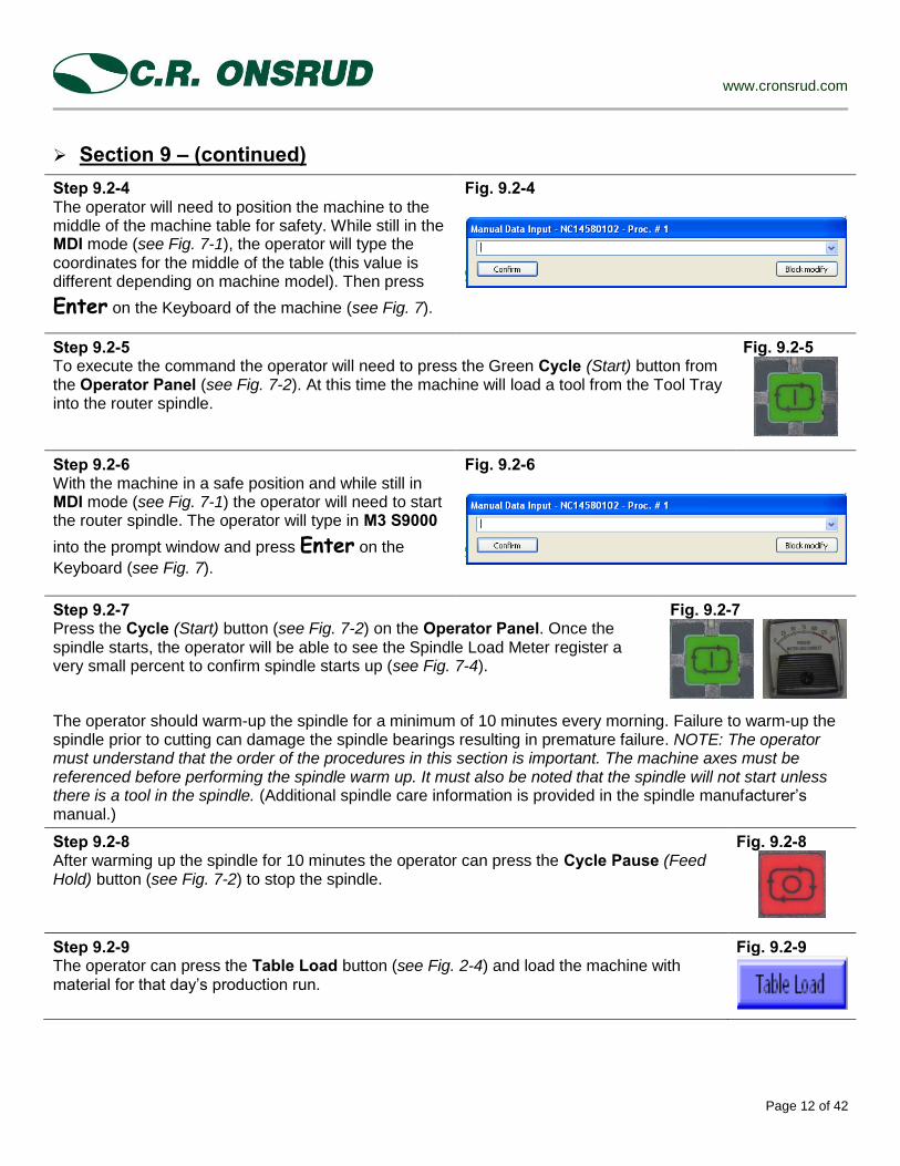
Step 9.2-4 The operator will need to position the machine to the middle of the machine table for safety. While still in the MDI mode (see Fig. 7-1), the operator will type the coordinates for the middle of the table (this value is different depending on machine model). Then press
Enter on the Keyboard of the machine (see Fig. 7).
Fig. 9.2-4
Step 9.2-5 To execute the command the operator will need to press the Green Cycle (Start) button from the Operator Panel (see Fig. 7-2). At this time the machine will load a tool from the Tool Tray into the router spindle.
Fig. 9.2-5
Step 9.2-6 With the machine in a safe position and while still in MDI mode (see Fig. 7-1) the operator will need to start the router spindle. The operator will type in M3 S9000
into the prompt window and press Enter on the
Keyboard (see Fig. 7).
Fig. 9.2-6
Step 9.2-7 Press the Cycle (Start) button (see Fig. 7-2) on the Operator Panel. Once the spindle starts, the operator will be able to see the Spindle Load Meter register a very small percent to confirm spindle starts up (see Fig. 7-4).
Fig. 9.2-7
The operator should warm-up the spindle for a minimum of 10 minutes every morning. Failure to warm-up the spindle prior to cutting can damage the spindle bearings resulting in premature failure. NOTE: The operator must understand that the order of the procedures in this section is important. The machine axes must be referenced before performing the spindle warm up. It must also be noted that the spindle will not start unless there is a tool in the spindle. (Additional spindle care information is provided in the spindle manufacturer’s manual.)
Step 9.2-8 After warming up the spindle for 10 minutes the operator can press the Cycle Pause (Feed Hold) button (see Fig. 7-2) to stop the spindle.
Fig. 9.2-8
Step 9.2-9 The operator can press the Table Load button (see Fig. 2-4) and load the machine with material for that day’s production run.
Fig. 9.2-9

www.cronsrud.com
Page 13 of 42
Section 10 – Machine Manual Mode
After the machine has been Homed, the operator can manually move the machine axes around. There are three methods that the operator can use to move the machine:
Manual Jog (see Step 10.1-1) - The selected axis will move while the operator presses and holds the green Cycle button. Once released the axis will stop moving.
Incremental Jog (see Step 10.2-1) - In conjunction with Jog Dir (see Fig. 1-6) and Jog Inc. (see Fig. 1-6) when selected the machine will move only the distance equal to the amount indicated in Jog Inc. (see Fig. 1-6).
HPG (Hand Pulse Generator) (see Step 10.3-1) - Works in conjunction with the Hand Pulse Generator (see Fig. 7-4) and Jog Inc. Fig. 1-6). When selected a full revolution of the hand wheel will move the selected axis the distance equal to the amount indicated in Jog Inc. Fig. 1-6).
Step 10.1-1 Manual Jog
Select Manual mode (see Fig. 7-1) and the desired axis
from the OSAI Process Controller screen (see Fig. 1-4) that the operator chooses to move.
Fig. 10.1-1
Step 10.1-2 The operator will need to select the desired positive or negative direction from the Jog Dir (see Fig. 1-6).
Fig. 10.1-2
Step 10.1-3 The operator will press and hold the Green Cycle button to move the axis and release it to stop the axis motion. The axis will move as long as the button is pressed.
Fig. 10.1-3
Step 10.2-1 Incremental Jog Select Incremental Jog mode (see Fig. 7-1) and the desired axis from the OSAI Process Controller screen (see Fig. 1-4) the operator chooses to move.
Fig. 10.2-1
Step 10.2-2 The operator will need to select the desired positive or negative direction from the Jog Dir (see Fig. 1-6).
Fig. 10.2-2
Step 10.2-3 The operator will need to select the desired distance the axis will move in the Jog Inc. field. This value ranges from 0.00001 to 1.00000, most common values are 1.00000, 0.10000, 0.01000, and 0.00100, as is changed by pressing the [ - ] button or [ + ] button.
Fig. 10.2-3
Step 10.2-4 The operator will press and hold the Green Cycle button; the axis will move the determined distance in Jog Inc. and then automatically stop. The axis will move as long as the button is pressed, once released the axis will stop moving.
Fig. 10.2-4

www.cronsrud.com
Page 14 of 42
Section 10 – (continued) Step 10.3-1 HPG (Hand Pulse Generator) Select HPG (see Fig. 1-5) and the desired axis from the OSAI Process Controller screen (see Fig. 1-4). A yellow message window 092 HPG ENABLED will appear letting the operator know that the HPG is activated. To exit the HPG mode
the operator can press the Manual mode button
Fig. 10.3-1
Step 10.3-2 The operator will need to select the desired distance the axis will move in the Jog Inc. field. This value ranges from 0.00001 to 1.00000, most common values are 1.00000, 0.10000, 0.01000, and 0.00100, as is changed by pressing the [ - ] button or [ + ] button.
Fig. 10.3-2
Step 10.3-3 The operator will then use the Hand Pulse Generator dial (see Fig. 7-4) to move the selected axis. One full revolution of the dial will cause the axis to move the distance indicated in the Jog Inc. field. If the increment was 1.00000 the one revolution equals a full inch of travel, where as one click would move only 0.01 of an inch.
Fig. 10.3-3
Step 10.4-1 Single Axis Home This mode allows the operator to Home one axis of the machine. The operator will select the Single Axis Home button from the Operator Panel (see Fig. 7-1).
Fig.10.4-1
Step 10.4-2 The operator will need to select the desired axis to home from the OSAI Process Controller screen.
Fig.10.4-2
Step 10.4-3 The operator will need to press the Green Cycle button (see Fig. 7-2) to execute the Home sequence. The axis selected will move to its zero position. This process is similar to Auto Home (see Step 9.1-1) except that only one axis will be moving.
Fig.10.4-3

www.cronsrud.com
Page 15 of 42
Section 11 – Tool Length Offsets Section 11 – Setting Up Tool Length:
The tool length offset is a variable the machine uses to offset the spindle position, so that the tip of the tool will position at a predetermined program Z zero position. In combination with the User Origin these values can offset the machine’s Absolute Zero position to match the program zero position.
This manual will show the operator three methods of entering tool lengths into the machine’s Offset Table.
First there is Manual Tool Set. (see Steps 11.1) Second is measuring the tools “Off Line” with a measuring device. (see Steps 11.2) Third is using the Auto Tool Set method (see Steps 11.3) (this method is an option and must be purchased).
Step 11.1-1 - Manual Tool Set –
Load a tool into the spindle. Go to MDI, type in M6 T# (enter the desired tool number needing to be entered), press Enter on the keyboard, and then the Green Cycle (Start) button (see Step 9.2-2 & 9.2-3 for details). This will load the first tool to be measured into the router spindle. Look in the Active Tool field on the main Process Controller screen (see Fig. 11.1-1). In example, 1.1 may be displayed referencing tool tray position 1 and length offset 1.
Fig. 11.1-1
Step 11.1-2
The operator will need to press the Table Set Up button (see Fig. 11.1-2) to access the vacuum activation. Activating vacuum in Zone 1 (see Section 3 for details), then press Return.
Fig. 11.1-2
Step 11.1-3 The operator will need to select the
MANUAL mode button (see Fig. 7-1) from
the Operator Panel, and select the X axis from the OSAI Process Controller screen. The selected axis, will high light in black (see Fig. 11.1-3 where Y axis is selected).
Fig. 11.1-3
Step 11.1-4 The operator will need to position the X axis at approximately 6 inches using the Jog Dir and pressing the green Cycle button (see Steps 10.1-1 to 10.1-3).
Fig. 11.1-4
Step 11.1-5 The operator will need to repeat Steps 11.1-3 and 11.1-4 to position the Y axis.
Step 11.1-6 The operator will need to select the Z axis (see Fig. 1-3) from the OSAI Process Control screen.
Fig. 11.1-6
Step 11.1-7 The operator will need to select the HPG button (see Fig.1-4) from the OSAI Process Control screen.
Fig. 11.1-7

www.cronsrud.com
Page 16 of 42
Section 11 – (continued) Step 11.1-8 The operator then needs to set the Jog Inc. to 1.00000 (or the highest setting) (see Fig. 1-7) by pressing the [ + ] on the screen.
Fig. 11.1-8
Step 11.1-9 Begin rotating the Hand Pulse Generator in a counter clockwise direction to bring the Z axis down toward the machine spoil board. When the tip of the tool is approximately ½ to 1 inch above the table stop axis motion, and change the Jog Inc. to 0.10000 by pressing the [ - ]. Begin bringing the tool tip down closer to the spoil board. At approximately 1/8 to 1/4 of an inch above the spoil board, change the Jog Inc. to 0.01000 and finish bringing the tip of the tool down until it touches the spoil board top.
Fig. 11.1-9
NOTE: The above step (11.1-9) is setting the Program Z zero position to the bottom of material. If the operator desires the Program Z zero to be the Top of material repeat the same steps as above (11.1-8 & 11.1-9), except bring the tip of the tool to the top of the material while it is on the machine table. WE RECOMMEND SETTING PROGRAM Z ZERO TO THE BOTTOM OF MATERIAL.
Step 11.1-10 Once the tip of the tool is on the top of the spoil board the operator will press the Tool Setup button (see Section 2 – Tool Setup Screen).
Fig. 11.1-10
Step 11.1-11 When inside the Tool Setup screen the operator needs to press the Man. Tool Set button from the middle of the screen. A prompt window will open called Tool offset prest – NCxxxxxxxx – Proc. #1 – [INCH] (this may differ due to machine options and model).
Fig. 11.1-11
Step 11.1-12 The operator will need to fill in the required fields with information so the machine knows where to go to retrieve the information. The fields are:
Offset Number: Type the number of the tool that was load into the spindle (i.e. if Tool 1 was loaded then 1 should be typed).
Reference Axis: This is the axis that the offset value will be applied to and should be Z.
Tool tip position: This field is used in direct relation to the use of UAO’s (User Absolute Origin’s – see Section 13). If UAO’s are not used this field is left at 0,0.
Fig. 11.1-12
Once the operator has filled in these fields press the OK button in the prompt window, or press the Enter
button on the keyboard. This will enter the value into the offset address for that tool, and the operator can look at the Tool Length field of the Process Controller screen (see Fig. 1-2) to see the value entered. NOTE: The machine will not move any axes after the value has been entered.
Step 11.1-13 The operator will press the Z axis Retract brining the Z axis into its raised position. The operator will then repeat Steps 11.1-1 to 11.1-13 for all tools needing to be touched off. This method if used will need to be done if the spoil board is surfaced or if a tool is changed.
Fig. 11.1-13

www.cronsrud.com
Page 17 of 42
Section 11 – (continued)
Step 11.2-1 – Measuring Tool Length Off Line – If the operator chooses
this method of entering Tool Lengths the operator will also need to work with the use of UAO’s (User Absolute Origins) (see Section 13).
This method of entering tool length offsets is done with a Digital Bench Top Tool Setter (see Fig. 11.2-1) that can be purchased by the customer. Turn power onto the device and bring the indicator to the top face of the base and press the ZERO/ ABS button to zero out the device. Once zeroed the device will be ready to use. NOTE: The operator will want to have all router bits, placed in collets, and locked down in the Tool Holder (see the Maintenance section of the Owner’s Manual for proper steps in changing and loading tools).
Fig. 11.2-1
Step 11.2-2
Bring the indicator up away from the base of the device ensuring that there is enough room to place the tool holder under the indicator tip (see Fig. 11.2-2). Now place the Tool Holder that needs to be measured into the device, and bring the indicator back down to the tip of the tool. Verify this number by checking it more then once. Record this value on a piece of paper and also note in what tool tray pocket position the tool will be placed. Repeat Steps 11.2-1 and 11.2-2 for all tools needing to be measured.
Fig. 11.2-2
Step 11.2-3 The operator will select the Utility button (see Fig. 11.2-3) from the bottom right of OSAI Process Controller screen. When the menu appears select the option of Table Editor. This will open a new window called OSAI Table Editor (see Fig. 11.2-4).
Fig. 11.2-3
Step 11.2-4
Once in the OSAI Table Editor window, the operator will select the Tables button from the bottom of the screen opening a menu. Offset Origin User Tools The operator will select Offset from the menu opening the Offset Variables Table (see Fig. 11.2-5).
Fig. 11.2-4

www.cronsrud.com
Page 18 of 42
Section 11 – (continued) Step 11.2-5 Inside the Offset Variable Table the operator will use the directional arrow keys on the keyboard to select the desired offset number. The offset number and the tool pocket number should match. (i.e. If the operator changes the bit in tool pocket position 1, then performs Steps 11.2-1 & 11.2-2, the operator (in this screen) will select Offset 1 to enter the value.) The measurement recorded in Step 11.2-2 will be entered into the
field labeled Length 1 and press Enter on the keyboard.
NOTE: The operator can also enter any diameter value if Tool Compensation is used in the programs. The diameter field will accept positive and negative values.
Fig. 11.2-5
The operator will need to stay in the OSAI Table Editor screen and repeat Step 11.2-5 for all tool lengths needed. These values do not need to be changed unless the operator takes the router bit out of the tool holder and replaces it with a different bit (e.g. a new tool, or a replacement bit).
Step 11.3-1 – Auto Tool Set NOTE: This method of setting tool length is NOT a standard feature, and would need to be purchased as an option on your machine. It must also be stated that this method CAN NOT be used with large diameter tools and profile tools. The large diameter tools and profile tools would need to use the method of measuring tools offline (see Fig. 11.2-1 to 11.2-5).
Step 11.3-1 The operator will begin by removing all Large tools from the Tool Tray. After this is completed press the Tool Setup button from the OSAI Process Controller screen.
Fig. 11.3-1
Step 11.3-2 The operator will then select the AUTO mode button from the Operator Panel (see Fig. 7-1)
Fig. 11.3-2
Step 11.3-2 From the Tool Setup screen the operator will press the Auto Tool Set which will open a prompt window on the screen.
Fig. 11.3-2
Step 11.3-3 In the prompt window the operator will be asked to Enter a letter for what it is to be touched off. The letter O stands for only one tool and a letter A stands for all tools in the tool tray (large tools have been removed from the tray). The operator will type a letter O into the box and then press
Enter on the key board.
Fig. 11.3-3
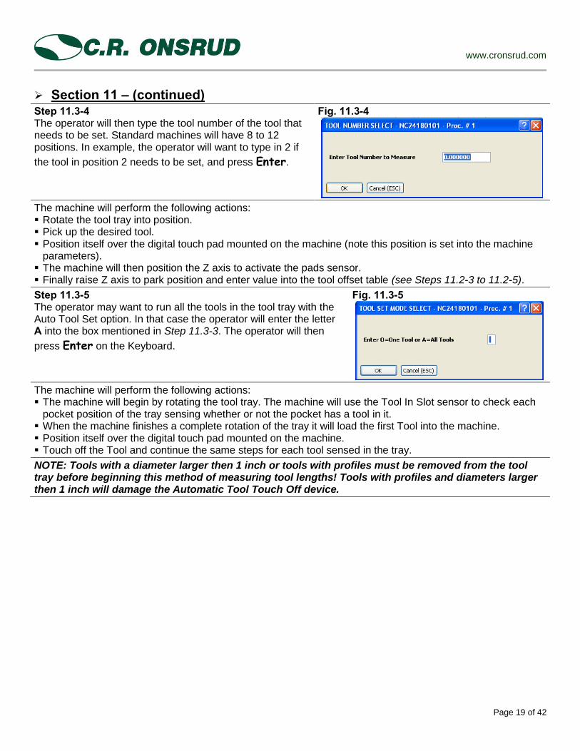
www.cronsrud.com
Page 19 of 42
Section 11 – (continued) Step 11.3-4 The operator will then type the tool number of the tool that needs to be set. Standard machines will have 8 to 12 positions. In example, the operator will want to type in 2 if
the tool in position 2 needs to be set, and press Enter.
Fig. 11.3-4
The machine will perform the following actions: Rotate the tool tray into position. Pick up the desired tool. Position itself over the digital touch pad mounted on the machine (note this position is set into the machine
parameters). The machine will then position the Z axis to activate the pads sensor. Finally raise Z axis to park position and enter value into the tool offset table (see Steps 11.2-3 to 11.2-5).
Step 11.3-5 The operator may want to run all the tools in the tool tray with the Auto Tool Set option. In that case the operator will enter the letter A into the box mentioned in Step 11.3-3. The operator will then
press Enter on the Keyboard.
Fig. 11.3-5
The machine will perform the following actions: The machine will begin by rotating the tool tray. The machine will use the Tool In Slot sensor to check each
pocket position of the tray sensing whether or not the pocket has a tool in it. When the machine finishes a complete rotation of the tray it will load the first Tool into the machine. Position itself over the digital touch pad mounted on the machine. Touch off the Tool and continue the same steps for each tool sensed in the tray.
NOTE: Tools with a diameter larger then 1 inch or tools with profiles must be removed from the tool tray before beginning this method of measuring tool lengths! Tools with profiles and diameters larger then 1 inch will damage the Automatic Tool Touch Off device.

www.cronsrud.com
Page 20 of 42
Section 12 – Drill Head (MSB) Length Offsets The MSB or Multi Spindle Block is an option that is purchased and built onto the machine. This section is for machine’s that have this option. If the operator’s machine does not have a MSB option on the machine Drill lengths will be measured using one of the methods in Section 11. Step 12.1 The operator will need to set up the Drill Head tool lengths for the machine before running jobs. The operator will need to go to the Drillhead Set Up screen (see Section 6, Fig. 6) and press the MSB Down button on the screen. This will lower the drill head into place. We offer 3 standard configurations of drill heads 9 spindle (all vertical) 13 spindle (all vertical) 15 spindle (11 vertical and 4 horizontal)
Fig. 12.1
Step 12.2 Once the MSB unit is down the operator will fire all the spindles down in the drill block by pressing the All Drill Heads Down button on the screen. All the drill spindles in the head will fire. All drills will be measured at the same time using the same tool length. We recommend using standard line boring drills of a 70 mm length and a shank diameter of 10mm.
Fig. 12.2
Step 12.3 With all of the drill spindles in the down position the MSB unit is ready to have the offset lengths set by the operator. The operator will need to activate vacuum on the table.
The operator will go to the Table Set Up screen and turn On vacuum to Zone 1, and then press Return.
Fig. 12.3
Step 12.4
The operator will now select the MANUAL
mode button (see Fig. 7-1) from the Operator Panel, and then select the X axis from the OSAI Process Controller screen. The selected axis, will high light in black (see Fig. 12.4 where Y axis is selected).
Fig. 12.4
Step 12.5 The operator will need to position the X axis at approximately 6 inches using the Jog Dir and pressing the green Cycle button (see Steps 10.1-1 to 10.1-3).
Fig. 12.5

www.cronsrud.com
Page 21 of 42
Section 12 – (continued) Step 12.6 The operator will need to repeat Steps 12.5 and 12.5 to position the Y axis. The operator needs to make sure his MSB head is entirely over the spoil board of the table.
Step 12.7 The operator now needs to select the Z axis (see Fig. 1-3) from the OSAI Process Control screen.
Fig. 12.7
Step 12.8 The operator will select the HPG button (see Fig.1-4) from the OSAI Process Control screen.
Fig. 12.8
Step 12.9 The operator then set the Jog Inc. to 1.00000 (or the highest setting) (see Fig. 1-7) by pressing the [ + ] on the screen.
Fig. 12.9
Step 12.10 Begin rotating the Hand Pulse Generator in a counter clockwise direction to bring the Z axis down toward the machine spoil board. When the tip of the drills are approximately ½ to 1 inch above the table stop axis motion, and change the Jog Inc. to 0.10000 by pressing the [ - ]. Begin bringing the drills down closer to the spoil board. At approximately 1/8 to 1/4 of an inch above the spoil board, change the Jog Inc. to 0.01000 and finish brining the drills down until the tips touch the spoil board top.
Fig. 12.10
NOTE: The above step (12.10) is setting the Program Z zero position to the bottom of material. If the operator desires the Program Z zero to be the Top of material repeat the same steps as above (12.1 to 12.10), except bring the tip of the drill to the top of the material while it is on the machine table. WE RECOMMEND SETTING PROGRAM Z ZERO TO THE BOTTOM OF MATERIAL.
Step 12.12 When inside the Drillhead Set Up screen the operator needs to press the Man. Tool Set button from the middle of the screen. A prompt window will open called Tool offset prest – NCxxxxxxxx – Proc. #1 – [INCH] (this may differ due to machine options and model).
Fig. 12.12
Step 12.13 The operator will need to fill in the required fields with information so the controller knows where to go to retrieve the information. The fields are: Offset Number: The operator will type in the number of the
intersecting bit 36 into this field. All the drills will look to this offset number for tool length.
Reference Axis: This is the axis that the offset value will be applied to and should be Z.
Tool tip position: This field is used in direct relation to the use of UAO’s (User Absolute Origin’s – see Section 13). If UAO’s are used the value entered into Axis 3(Z) of the origin is the same value entered in Tool Tip Position. If UAO’s are not used this field is left at 0.0. The operator will then press the OK button.
Fig. 12.13

www.cronsrud.com
Page 22 of 42
Section 12 – Drill Head (MSB) Length Offsets Step 12.14 Once the length has been set the operator will need to retract the drills and the MSB unit. From the Drillhead Set Up screen the operator will press the All Drill Heads Up
button from the screen.
Fig. 12.14
Step 12.15
After the drill heads are retracted the operator will now press the MSB Up Button from the screen. Retracting the entire unit to its parked position. Then press the
Drillhead Set Up button to return to the Tool Setup screen.
Fig. 12.15
Step 12.16 From the Tool Setup screen the operator will need to press Z axis Retract button to retract Z to its park position.
Fig. 12.16

www.cronsrud.com
Page 23 of 42
Section 13 – Origins & UAO’s (User Absolute Origins) In this section the operator will learn about the use of Origins in the OSAI Control. An Origin is a variable used by the control system to “shift” one or more of the machine’s axes from a known position. This shift can be done as an Incremental move or as an Absolute move. In this manual we will discuss the use of User Absolute Origins or also known as UAO’s, and how they are used to “shift” the machine’s Absolute Zero position to match the Program Zero position. There is a table with ten absolute origins the programmer or operator can use in the program. To use the UAO’s (User Absolute Origins) there are two criteria:
1.) The G-Code program to be run must have a line of code that calls out the use of an Origin and which Origin to be use. The value is 1-10, and must be in the following format – (UAO,x) (note: x represents a value of 1-10).
2.) The operator must set up and enter the values to be use by the origin. These values are entered at the machine. Step 13.2 will show the operator how to get to the tables.
Steps 13.1 will give an example of how and where the origin is called in the program. Steps 13.2 will show the operator how to access the Origin Table and enter the values.
NOTE: As a CNC manufacturer we will not discriminate as to what CAD/ CAM software a customer uses with our machine. We will work with any software company to assist them in creating proper code for our machine to run. The examples given in this step are from the software that we distribute and support.
Step 13.1-1 To the right is some example G - Code showing the beginning of a program. Highlighted in red shows how the UAO is called out before the machine performs a tool change. When the machine reads this line of code it will go look at the value(s) inside the Origin Table number 1. This is a very common UAO call for nested base processing. Note: Please see Section 15 for an over view explanation of basic G – Code.
Fig. 13.1-1 ;FILENAME EXAMPLE
;MACHINE CONFIGURATION = 0, 0, 148., 1, 1, 0, 1, 0, 0, 1 ;(ESTIMATED CYCLE TIME = 0MINS 14SECS) G70 G27 G90 G80 G40 MOV= 72 VFF= 1 FCT=.0001 G00 G79 Z(@ZPARKP1)
(UAO,1) ;OPERATION CHANGE M06 T1
Step 13.1-2 To the right is more example of G - Code showing the beginning of a program. Like the example above the UAO call is highlighted in red. When the machine reads this line of code it will activate the value(s) inside the Origin Table number 2. Note: Please see Section 15 for an over view explanation of basic G – Code.
Fig. 13.1-2 ; EXAMPLE2
;*** TOOL LIST *** ; TOOL - 01 DIA. - .5 T1 - ;***************** N5 MOV=72 N10 VFF=1 N15 FCT=.00001
N20 G00 G79 Z(@ZPARKP1)
N25 (UAO,2) ;( TOOL - 01 ) N30 M06 T1

www.cronsrud.com
Page 24 of 42
Section 13 – (continued) Step 13.2-1 The operator will need to access the machine’s origin tables in order to enter the desired values to be used. From the main OSAI Process Controller, the operator will press the Utility button in the bottom left corner. From the menu that appears, select Table Editor (see Fig. 13.2-1), this will open the OSAI Table Editor window.
Fig. 13.2-1
Step 13.2-2 From the bottom of the OSAI Table Editor the operator will need to select the Tables button (Fig. 13.2-2) to open the menu. From this menu the operator will select Origin. This will open the Origin Table which is where the operator will enter his values.
Fig. 13.2-2
Step 13.2-3 With the Origin Table open the operator will use the directional arrow keys on the Keyboard to highlight the desired table number. In the image to the
right (see Fig. 13.2-3), Origin Table 1 is highlighted. By pressing the Enter button on the keyboard, the operator will be able to access the table to enter new values.
Fig. 13.2-3
Step 13.2-4 The operator will enter the desired values into the corresponding axes. In this example we will be shifting the X axis .5 inches, Y axis .5 inches, and the Z axis .73 inches. Once the values are entered and verified the operator will press OK, and see the values in the Origin Table under table 1.
Fig. 13.2-4

www.cronsrud.com
Page 25 of 42
Section 13 – (continued) Step 13.2-5 Using the directional arrows, the operator will select the next Origin that needs to be set up. The operator will repeat Steps 13.2-3 to 13.2-4 for all desired origins as needed. Fig. 13.2-5 shows origins 1 and 2 with values.
Fig. 13.2-5
To review this section, in Steps 13.1-1 in the program EXAMPLE the program calls out the use of (UAO,1). In Steps13.2-1 to 13.2-4 the operator entered the desired values into Origin 1 to shift the machine. When the program executes the UAO call in the program the control will look at the values in Origin and shift the Machine Absolute Zero by the amounts designated in the table. The program will believe it is running at X0, Y0, and Z0, but physically the machine will be running it at X0.5, Y0.5, and Z0.73. This is referred to as an Origin Shift or Work Shift.
Section 14.1 – Part Program Management Once the CAD/ CAM software has produced the G – Code program to be run on the machine, the operator will need to load that program into the UPP Directory (User Part Program Directory). The operator will have two different ways in which program(s) can be loaded into the UPP Directory. 1.) Connect the machine to the network of the company and create a shared folder in which to place the
program into, so that the operator can access them from the OSAI Operator console. 2.) Place the program(s) onto a USB memory device, then bring the device to the machine and copy the
program into the OSAI Operator Console. This manual will instruct the operator how to load the programs into the UPP Directory and then call them up to be run. The instructions will be for the loading of programs off of a USB Memory Device into the UPP.
Step 14.1-1 The operator will plug the USB Memory Device into the OSAI WinMedia Panel (the port is labeled on the right side of the screen) and the Windows operating system should Auto Play the device opening a prompt window. The operator will select the option Open folder to view files using Windows Explorer (see Fig. 14.1) from the screen.
Fig. 14.1-1
Step 14.1-2 The operator will see the prompt window for the device appear. Inside the window will be a list of jobs that need to be run. The operator will need to select the job(s) to run on the machine. If this method is used, it is recommended to keep the Memory Device clean to avoid confusion in choosing the job to be run.
Fig. 14.1-2

www.cronsrud.com
Page 26 of 42
Section 14.1 – (continued) Step 14.1-3 The operator will need to select all the jobs to be run. To do this the
operator will press Ctrl & A to highlight all the jobs blue (see Fig 14.3).
Fig. 14.1-3
Step 14.1-4 The operator will need to cut the jobs off the USB Memory Device by
pressing Ctrl & X on the keyboard (see Fig. 14.4).
Fig. 14.1-4
Step 14.1-5 The operator will click on the Start button (at the bottom left of screen) then select the My Computer icon from the list on the right. The My Computer window will open (see Fig. 14.5).
Fig. 14.1-5
Step 14.1-6 The operator will need to open the UPP Drive that should appear in the My Computer window. This drive should be mapped out, in the example shown the designation is Upp on ‘NC14580101’ (Z:). The operator will double click on the Upp icon in order to gain access to the UPP folder.
Fig. 14.1-6
Step 14.1-7 The operator will then select the UPP Folder and double click it to open the folder. This gives the operator access to the storage area for the part programs (jobs) to be run.
Fig. 14.1-7
Step 14.1-8
The UPP Directory will open. The operator will press Ctrl & V this will paste the
programs in the UPP. The operator will see the new programs highlighted in the screen. This is the storage area that the operator will store the programs in. The operator can create sub directory folders inside the UPP to help organize the UPP directory. The programs stored in this area can have one of three extensions those extensions are: .txt .nc .anc
Fig. 14.1-8
NOTE: The operator can close the windows discussed in the previous steps (see Steps 14.1 to 14.8) and Maximize the OSAI Process Controller.

www.cronsrud.com
Page 27 of 42
Section 14.2 – Activation and Running Part Programs Step 14.2-1 With the OSAI Process Controller open, the operator will need to access the part
programs. Press the Part Program button and from the menu, the operator will want to select Part Program Management. If the operator is finished running a program, select Deactivate Part Program and the active program will disengage.
Fig. 14.2-1
Step 14.2-2 The Part Program Management prompt window will open. The operator will want to select the desired program to run. The program will highlight as in Fig. 14.2-2 showing that the program EXAMPLE.ANC is the selected program. The operator has some functionality in this window; for example, one can rename a desired program, delete a previously run program, deactivate an active program, and so on. Outside of activation and deactivation of a program, all functionality is a form of editing the existing programs or directory.
Fig. 14.2-2
Step 14.2-3 Once the desired program is selected, the operator will need to activate the program in order to run it on the machine. The operator achieves this by pressing the Activate button on the side of the Part Program Management window. The operator will see the program code appear in the bottom left of the OSAI Process Control Screen under PROGRAM MESSAGE. Once activated, the operator needs to press the Exit button to close the Part Program Management window.
Fig. 14.2-3
Step 14.2-4 The program is activated and can be run. The operator will need to put the machine in Auto mode, make sure the work area is clear of debris and personnel, turn on dust collection, apply vacuum to the table, and check to make sure the proper Z shift is entered (if a Dry Run is used) in order to cycle the program. NOTE: For operator’s whom are not familiar with running and programming a CNC router we recommend that the operator “Dry Runs” the program at the beginning to become comfortable and familiarize themselves with the CNC machine and it motions.
Fig. 14.2-4
NOTE: Prior to running a job the operator will want to ensure all variables are entered into the control and that all safety measures are taken. Below are 7 steps that the operator can take to ensure prior running:
1.) Tool Length: Ensure tool lengths are correct and entered into the control 2.) Origins: Ensure that Origin (Fixture Offsets) are correct for the program being run 3.) Z Shift: Ensure that the proper Z Shift (Material Offset) is set for a Dry Run or set to Zero for
actually cutting material 4.) Program: Check and ensure that the program is loaded in the control and Activated to run 5.) Overrides: Ensure that all the overrides are in the correct position for running the program 6.) Vacuum: Ensure vacuum is on and applied to the work piece and overrides are in correct safety
position 7.) Dust Collection: Ensure Dust Collector is on and blast gates are open

www.cronsrud.com
Page 28 of 42
Section 14.3 – Program Dry Run Step 14.3-1 To “Dry Run” or to run the program in the air, the operator will need to set the Z axis Shift. Press the Set Z Shift on the screen.
Fig. 14.3-1
Step 14.3-2 The Z axis Material Offset window will open. The operator will enter the “shift” needed into the Enter Z value on the screen. This shift value will change based on the material thickness being run. The shift is based off of the Z axis final depth in the part program. This value should be larger then the material thickness.
Fig. 14.3-2
Step 14.3-2 In example, if the material to be cut is 1 inch thick, then the Z shift value should be 1.25 inches or greater. When the program runs, the tip of the tool will be .25 inches off the top of the material. Once the “Dry Run” is completed (it is recommended to run through all tool changes in the program) the operator will need to change the Z Shift back to 0.0 (zero) in order for the tool to cut the material.

www.cronsrud.com
Page 29 of 42
Section 15.1 – General NC Code explanations
G-Code FUNCTION M-Code FUNCTION G00 Machine Rapid Move M00 Program stop/ Pause
G01 Program Feed Move M01 Program stop optional
G02 Clockwise Interpolation of an arc M02 End of Program
G03 Counter clockwise Interpolation of an arc M03 Spindle Rotation CW
G16 Free Interpolation Plane Selection (used for interpolation of slave axis)
M04 Spindle Rotation CCW
G17 XY Interpolation Plane M05 Spindle Stop
G40 Cancel cutter compensation M06 Tool change/Offset Activation
G41 Enable cutter comp. on the left side of geometry
M30 End of Program, reset and rewind
G42 Enable cutter comp. on the right side of geometry
M98 Brushes Down
G70 Inch units M99 Brushes Up
G71 Metric units
G79 Absolute (in ref. to home position)
G90 Absolute (in ref. to current origin)
G91 Incremental (in ref. to previous move)
Section 15.2 – Onsrud Specific NC Code explanations
Specific G-Code
FUNCTION Specific G-Code
FUNCTION
G200 Automatic Vacuum On & Pop-Up Down by Table
G331 Enables the X axis in Process 2 when launched by Process 1
G201 Automatic Vacuum Off & Pop-Up Up by Table
G350 Enables U axis in Process 1 and Releases X axis in process 2
G300 Disable the X axis in Process 1 G351 Enables U axis in Process 2 and Releases X axis in process 1
G301 Enables the X axis in Process 1 G352 Process 1 puts all axes back to normal
G302 Enables Process 2 X axis in Process 1 and calls it U
G353 Process 2 puts all axes back to normal
G310 Disable the X axis in Process 1 when launched by Process 2
G500 Motion Filtering Macro
G311 Enables the X axis in Process 1 when launched by Process 2
G600 Tool Change Routine for Multi-Spindle m/c
G320 Disable the X axis in Process 2 G699 Resets the retractable Probe (Probe retracts then Z retracts)
G321 Enable the X axis in Process 2 G700 Work surface probing routine (Modal), collected values are stored in E101 to E199
G322 Enables Process 1 X axis in Process 2 and calls it U
G999 Cancel G700 to G998 Macro’s
G330 Disable the X axis in Process 2 when launched by Process 1

www.cronsrud.com
Page 30 of 42
Section 15.2 – (continued)
Specific M-Codes
FUNCTION Specific M-Codes
FUNCTION
M18 Tool Clamp w/o Tool (Single spindle) M130 All Vacuum Zones on M20 Tool Clamp (Single spindle) M131 Vacuum Zone 1 on
M21 Tool Release (Single spindle) M132 Vacuum Zone 2 on
M22 Cone Air On (Single spindle) M133 Vacuum Zone 3 on
M23 Cone Air Off (Single spindle) M134 Vacuum Zone 4 on
M24 Head Up (Single spindle) M135 Vacuum Zone 5 on
M25 Head Down (Single spindle) M136 Vacuum Zone 6 on
M34 Pull Spindle from Process 2 into Process 1 M137 Vacuum Zone 7 on
M35 Release spindle from Process 1 back to Process 2 M138 Vacuum Zone 8 on
M66 Tool in Spindle Preset M139 Vacuum Zone 9 on
M70 Raise All Vacuum Pods M140 All Vacuum Zones off M71 Raise Vacuum Pod 1 M141 Vacuum Zone 1 off
M72 Raise Vacuum Pod 2 M142 Vacuum Zone 2 off
M73 Raise Vacuum Pod 3 M143 Vacuum Zone 3 off
M74 Raise Vacuum Pod 4 M144 Vacuum Zone 4 off
M75 Raise Vacuum Pod 5 M145 Vacuum Zone 5 off
M76 Raise Vacuum Pod 6 M146 Vacuum Zone 6 off
M77 Raise Vacuum Pod 7 M147 Vacuum Zone 7 off
M78 Raise Vacuum Pod 8 M148 Vacuum Zone 8 off
M79 Raise Vacuum Pod 9 M149 Vacuum Zone 9 off
M80 Lower All Vacuum Pods M154 Request RESET mode
M81 Lower Vacuum Pod 1 M155 Request FOLLOW mode
M82 Lower Vacuum Pod 2 M156 Request TORQUE mode
M83 Lower Vacuum Pod 3 M157 Request HOLD mode
M84 Lower Vacuum Pod 4 M158 Change OS3 max. current
M85 Lower Vacuum Pod 5 M159 Restore OS3 max. current
M86 Lower Vacuum Pod 6 M200 All Heads Up M87 Lower Vacuum Pod 7 M201 Head 1 Up
M88 Lower Vacuum Pod 8 M202 Head 2 Up
M89 Lower Vacuum Pod 9 M203 Head 3 Up
M90 Raise Moveable Probe M204 Head 4 Up
M91 Lower Moveable Probe M205 Head 5 Up
M100 Dual Process Slaving Enable M206 Head 6 Up
M101 Dual Process Slaving Disable M207 Head 7 Up
M110 All Roller Clamp Zones enabled M208 Head 8 Up
M111 All Roller Clamp Zones disabled

www.cronsrud.com
Page 31 of 42
Section 15.2 – (continued)
Specific M-Codes
FUNCTION Specific M-Codes
FUNCTION
M210 All Heads Down M300 All Tools Clamp M211 Head 1 Down M301 Head 1 Tool Clamp
M212 Head 2 Down M302 Head 2 Tool Clamp
M213 Head 3 Down M303 Head 3 Tool Clamp
M214 Head 4 Down M304 Head 4 Tool Clamp
M215 Head 5 Down M305 Head 5 Tool Clamp
M216 Head 6 Down M306 Head 6 Tool Clamp
M217 Head 7 Down M307 Head 7 Tool Clamp
M218 Head 8 Down M308 Head 8 Tool Clamp
M220 All Brushes Up M310 All Tools Release M221 Head 1 Brushes Up M311 Head 1 Tool Release
M222 Head 2 Brushes Up M312 Head 2 Tool Release
M223 Head 3 Brushes Up M313 Head 3 Tool Release
M224 Head 4 Brushes Up M314 Head 4 Tool Release
M225 Head 5 Brushes Up M315 Head 5 Tool Release
M226 Head 6 Brushes Up M316 Head 6 Tool Release
M227 Head 7 Brushes Up M317 Head 7 Tool Release
M228 Head 8 Brushes Up M318 Head 8 Tool Release
M230 All Brushes Down M320 All Cone Air on M231 Head 1 Brushes Down M321 Head 1 Cone Air On
M232 Head 2 Brushes Down M322 Head 2 Cone Air On
M233 Head 3 Brushes Down M323 Head 3 Cone Air On
M234 Head 4 Brushes Down M324 Head 4 Cone Air On
M235 Head 5 Brushes Down M325 Head 5 Cone Air On
M236 Head 6 Brushes Down M326 Head 6 Cone Air On
M237 Head 7 Brushes Down M327 Head 7 Cone Air On
M238 Head 8 Brushes Down M328 Head 8 Cone Air On
M240 Open Tool Rack Cover / Tray #1 Out M330 All Cone Air off M241 Close Tool Rack Cover / Tray #1 In M331 Head 1 Cone Air Off
M242 Tray #1 Down M332 Head 2 Cone Air Off
M243 Tray #1 Up M333 Head 3 Cone Air Off
M250 Tray #2 Out M334 Head 4 Cone Air Off
M251 Tray #2 In M335 Head 5 Cone Air Off
M252 Tray #2 Down M336 Head 6 Cone Air Off
M253 Tray #2 Up M337 Head 7 Cone Air Off
M290 Enable X axis +ve s/w limit M338 Head 8 Cone Air Off
M291 Disable X axis +ve s/w limit

www.cronsrud.com
Page 32 of 42
Section 15.2 – (continued)
Specific M-Codes
FUNCTION
M340 Raise All Vacuum Pop-ups
M341 Raise Vacuum Pop-up 1
M342 Raise Vacuum Pop-up 2
M343 Raise Vacuum Pop-up 3
M344 Raise Vacuum Pop-up 4
M345 Raise Vacuum Pop-up 5
M346 Raise Vacuum Pop-up 6
M347 Raise Vacuum Pop-up 7
M348 Raise Vacuum Pop-up 8
M349 Raise Vacuum Pop-up 9
M350 Raise Vacuum Pop-up 10
M351 Raise Vacuum Pop-up 11
M352 Raise Vacuum Pop-up 12
M353 Raise Vacuum Pop-up 13
M354 Raise Vacuum Pop-up 14
M355 Raise Vacuum Pop-up 15
M356 Raise Vacuum Pop-up 16
M360 Lower All Vacuum Pop-ups
M361 Lower Vacuum Pop-up 1
M362 Lower Vacuum Pop-up 2
M363 Lower Vacuum Pop-up 3
M364 Lower Vacuum Pop-up 4
M365 Lower Vacuum Pop-up 5
M366 Lower Vacuum Pop-up 6
M367 Lower Vacuum Pop-up 7
M368 Lower Vacuum Pop-up 8
M369 Lower Vacuum Pop-up 9
M370 Lower Vacuum Pop-up 10
M371 Lower Vacuum Pop-up 11
M372 Lower Vacuum Pop-up 12
M373 Lower Vacuum Pop-up 13
M374 Lower Vacuum Pop-up 14
M375 Lower Vacuum Pop-up 15
M376 Lower Vacuum Pop-up 16

www.cronsrud.com
Page 33 of 42
Section 16 – EE Fault Codes for C.R. Onsrud OSAI Control
EMERGENCY MESSAGES (User Manual, DAC DAM Sercos Manual)
Code Message Description Remedial action
EE001 Servo error axis
Positioning or following error
greater than the configured value. Non-locking error
(ERRO status).
Exit with reset.
EE002 Skew Error Axis
Split axes positioning or
following error greater than the
configured value. Non-locking error (ERRO status).
Exit with reset.
EE003 Encoder phase error
Erroneous encoder
configuration. Non-locking
error (ERRO status).
Exit with reset.
EE004 Timeout tolerance error
The axis is out of tolerance after
the specified time. Non-locking
error (ERRO status).
Exit with reset.
EE005 Inpos tolerance error
The axis is out of tolerance.
Non-locking error (ERRO
status).
Exit with reset.
EE006 Broken wire detection
Broken wire detected in the
transducerr cable. Locking error
(EMERG status).
Switch off the system.
EE007 Watch dog axis
The axes boards have not been
refreshed in the specified time. Locking error (EMERG status).
Switch off the system.
EE008 Divide by zero
axis
Calculation error (division by
zero). Locking error (EMERG
status).
Switch off the system.
EE009 Invalid command
axes
Request not valid for this board.
Locking error (EMERG status). Switch off the system.
EE010 Escape found axis Coprocessor error. Locking
error (EMERG status). Switch off the system.
EE011
Software
overtravel limit
with HPG
This emergency is given by the
axis board when the axis reaches the software travel limit.
Non-locking error.
Jog the axis in the opposite direction.
EE012 HPG software
overtravel exit
The axis board generates this
message to indicate that the axis
has returned within the software travel limit.
EE013 WatchDog - CAN
I/O module
CANOpen I/O devices have not
beenrefreshed within the
allotted time. Lockingerror (EMERG status)
Switch off the system
EE014
CAN
communication
error
Transmission or reception error hasoccurred on CAN Open bus
Check connections and turn off the system
EE015
WatchDog -
FastWire I/O module
FastWire I/O devices have not been refreshed within the
allotted time. Lockingerror
(EMERG status)
Switch off the system

www.cronsrud.com
Page 34 of 42
EE016
FastWire
communication
error
Transmission or reception error
on the FastWire bus. The field
DEVICE indicates the node (*) causing the error. The field
ERROR provides further
information useful for debugging and is of no
importance to the end user.
(*) ‘node’ means any device which can be connected to the
FastWire (e.g. drives, bridges,
I/Os, etc.).
Check the bus
connections and the
termination.
EE020 Plus shutdown
request
Machine shutdown request.
Non-locking error (ERRO).
Exit with reset.
Note: Not displayed as
filtered from human interface.
EE021 Plus watch dog
The logic board has not
responded within the hardware-
set interval. Locking error (EMERG status).
Switch off the system.
EE022 Plus divide by zero
The logic task has divided by
zero. Locking error (EMERG
status).
Switch off the system.
EE023 Plus invalid op-
code
Request not allowed to the logic
task. Locking error (EMERG status).
Switch off the system.
EE024 Plus I/O ring
failure
I/O ring failure. Locking error
(EMERG status). Switch off the system.
EE025
Plus coprocessor
exception or
WinPlus
Exception
WinPlus/Coprocessor error in the logic task. Locking error
(EMERG status).
Switch off the system.
EE026 Plus realtime task
overrun
The logic task has not been assigned a sampling time
interval. Locking error
(EMERG status).
Switch off the system.
EE027
Axis hw
overtravel limit reached
This emergency is generated by
the user logic when the axis
reaches the hardware overtravel microswitch. Non-locking error
(ERRO).
1) Exit with reset.
2)Jog the axis within the limits.
EE028 Exit over travel
hardware
This message is generated by the logic task to indicate that
the axis has returned within the
hardware overtravel limits..
Note: It is a warning.
EE029
Too many no wait
requests from Logic
The logic has sent too many no
wait requests.
Contact the Technical
Assistance service
EE030 Ghost interrupt
The system cannot interpret the
interruption. It is a locking error (EMERG status).
Switch off the system.
EE031 Front Panel anomaly
General front panel failure:
watchdog, coprocessore, parity error, etc. Locking error
(EMERG status).
Switch off the system.
EE032 False interrupt
This message indicates that a
false interrupt has been
detected.
Contact the Technical Assistance service.

www.cronsrud.com
Page 35 of 42
EE033
Unrecoverable
Remote I/O
Failure
An anomaly has been detected
during data reception/transmission on I/O
Ring.
Switch-off the system.
EE034 Recoverable Remote I/O
Failure
An anomaly has been detected during data
reception/transmission on RIO.
Try to remove the anomaly cause and
reset the system.
SERCOS DRIVE ERRORS EE46 Bit Description - Error code in S129
IDN EE47 Bit Description
Code Message Description Remedial action 15
0203, 0206,xxxx.
Indicates one or more of the
following errors: Power supply error (PSU)
Blocked motor
EEPROM error Op System Error
Drive Error
15 Parameter 495 Bit 15
EE040
Over signal
distorsion on optical fibre
An excessive distorsion of the
optical fiber signal has been detected.
Switch off and then on
again. 14 14
EE041
Interrupt
trasmission on optical fibre
The optical fiber signal has been interrupted. Check the optical
fiber cable and all the
connections.
Switch off and then on
again. 13 13
EE042 AT Telegram missing
Data loop communication with D.S.I. driver missing.
Switch off and on again; if the anomaly
persists, contact the
Technical Assistance service.
12 12
EE043
D.S.I.
Initialization
phase error
Error during initialisation phase. Contact the Technical Assistance service.
11 0601,0602 Excessive position Error
11
EE044 Anomaly on
service channel
Anomaly when sending commands from Master to
D.S.I. driver.
System reset. 10 10
EE045 Anomaly on D.S.I.command
execution
Anomaly during command
execution.
Reset the system and remove the cause of
the error.
9 9
EE046 Drive shut down: class 1 diagnostic
Error coming from "class 1 diagnostic" drive.
See the D.S.I. drive documentation.
8
0201,0205
Bus Overvoltage, or Power group
overtemperature
8
EE047
Shut down
warning: class 2 diagnostic
Anomaly signal non-locking
coming from D.S.I. "class 2 diagnostic" driver.
See the D.S.I. drive
documentation. 7
0202
Overcurrent 7
EE048
D.S.I. Fault:
anomaly during
anomaly
Locking error, when handling
an anomaly caused by the drive.
Switch off the system and contact the
Technical Assistance
service.
6 0207 > 020D
Power Transistor Error 6
EE049 Axis enable request not
allowed
The request to enable an axis reaches the system while it is
already performing the
calculations for the movement of the axis that has not yet been
enabled (e.g. the request to
enable the axis by PLUS arrives after "consent for the
movement")
Eliminate the error by
executing a Reset 5
0300>0304,0800>0808,0A00>0A08 Error in encoder 1 (X24) and/or
Encoder 2 (X25)
5
4 0204
Interference on the 24v PSU 4

www.cronsrud.com
Page 36 of 42
3 3
2 0501 Motor overtemperature
2 Parameter 151 bit 7 Motor overtemperature
1 1
Parameter 115 bit 6 Power
supply temperature >80
deg.
0
0401
Software motor temperature protection
0
Parameter 93 bit 4 Sftware protecion: motor
temperature > alarm level
(P088)
MECHATROLINK ANOMALIES
EE050 Axis board
memory failure
Mechatrolink axis board not detected by hardware
diagnostics at CNC power up,or
board failure.
Check drive addresses for axis
characterisation in
AMP.As an alternative, fit a new
board.
EE052 Communication
error
Communications with the drive
have been broken off. If the ALARM code is ‘FFFF’ a
synchronisation error has
occurred, otherwise it is a drive related error (see drive
documentation)
Check drive integrity
and parameters. Check Mechatrolink
communication wiring
harness and the communication cable
termination (plug).
EE053 Drive alarm The drive has notified an error.
For the ALARM codes, see the drive documentation.
Check drive
parameters and, if it is a dynamics problem,
extend check to AMP dynamic parameters.
Eliminate drive alarm
cause and RESET system.
EE054 Command
timeout
The drive failed to perform or
accept a command within the
maximum allotted time (five seconds). The value of the
ALARM code is not significant.
Check drive integrity
and parameters. If the
anomaly persists, contact the Technical
Service.
Fastwire
EE055
Axes Board
Memory Test
Failed
At start-up the CNC hardware
diagnostics found that the
OS8531 axes board was faulty.
Replace the board.
EE056 Drive/Bridge not
Connected Axis n
At start-up the CNC did not find
a drive under the address
configured in AMP for the indicated axis on the FastWire
bus.
check if the address on
the drive corresponds
to the one configured in AMP; check the
cable connections.
EE057
Drive Command
Error Axis n Error:eeee
Error while executing a
command during the operation phase.
2 (Drive Off), 3 (Drive
On), 4 (Hold)
Code eeee Description Possible causes
1000 invalid axis ID internal CNC error
1001 Timeout on a command issue drive does not respond
1002 communication channel
engaged
internal CNC error
1003 axis inhibited because of severe error
The axis has been inhibited earlier
because of a severe
error

www.cronsrud.com
Page 37 of 42
1004 non digital axis attempt to work with
an analog axis
1005 invalid request application error
1006 invalid command Internal CNC error
2002 command failed Internal CNC error
2003 invalid drive ID Internal CNC error
2004 Drive engaged Internal CNC error
2005 invalid request Internal CNC error or application error
2007 wrong monitoring data CNC or drive error during monitoring
2101 command cannot be executed illegal operation
2102 monitoring table overflow request to monitor
more than 16 variables
2103 Monitoring already active Monitoring already active
2104 No variable to be monitored No variable to be
monitored
2105 error during transmission Malfunctioning on the
internal serial port
2106 timeout error in transmission Malfunctioning on the
internal serial port
2107 timeout error in reception Malfunctioning on the internal serial port
2108 checksum error Malfunctioning on the internal serial port
2109 echoing error Malfunctioning on the
internal serial port
2110 Hyperface error Malfunctioning on the
encoder serial port
2111 feedback table overflow too many feedback
variables
2112 wrong variable ID non existing variable
2113 parameter table overflow too many parameters
selected for the
command
2114 wrong parameter ID non existing parameter
2115 Inconsistent Dry state parameter
write
2116 invalid memory address
2117 inconsistent data in sequencer
2118 inconsistent power board size
data
2119 Point2Point command not
available
2120 offset identification not available
2121 synchronisation timeout on
ROTC
2122 wrong FPGA register ID reprogram FPGA
2123 location number overflow

www.cronsrud.com
Page 38 of 42
2124 Qep counter release timeout DSP malfunction
2125 external Qep TD counter release timeout
DSP malfunction
2126 no encoder interface connected
2127 power error power board
malfunction
EE058 Drive Alarm Axis X
Alarm:aa
Drive alarm during operation. Eliminate the cause and Reset
Alarm: aa Description Possible causes Type
of stop
Recommended action
30 (Models B &
C only)
Brake resistor circuit
malfunction
faulty brake resistor
either too low or short
circuit,
IGBT
Open
Check the resistance of the brake
jumper or check the earth connections.
31 DSP Watchdog Firmware version error.
IGBT Open
Reload drive firmware
32 NMI triggered Firmware version
error.
IGBT
Open Reload drive firmware
33 24V power supply fault faulty drive
34 Initial position error. SYNCHS error (QeP and
SinCos not congruent).
Motor moving, from external causes, during
the initialization phase.
.
IGBT
Open Cycle the power
40 Drive overheat duty cycle too heavy, Cycle is using too
much current.
Ramp
Down
Reduce the acceleration or cool the
heat sink.
41 Motor overheat or thermal
protection fault
duty cycle too heavy or
thermal sensor not connected, or sensor
not cooled after high
temperature rise. Ramp Down
Reduce the acceleration or cool the motor.
RAMP DOWN The drive
continues to check the movement of the motor,
and it decelerates
according to the value in parameter 37 (Maximum
acceleration of the motor),
up to the complete stop of the motor. If fitted the
motor brake is applied.
42 (A) Drive overcurrent or short
circuit IGBT module overcurrent.
overcurrent in the
drive.
Over current in the
braking resistance
IGBT module
overtemperature
Dyn. 0 Vel
Check the motor phasing. Check the
drive earth connection. . Check the connections to the brake
resistor. .
Check cooling and reduce the dynamics of the operating cycle
Anomaly in PSU control
DYN. 0 VEL. The drive,
without checking velocity and position of the motor,
it applies the declared
current in parameter 66 (Value fixed terna of
ramp) to arrest the
movement, up to velocity zero. If fitted the motor
brake is applied
42 (B & C) Drive overcurrent or short
circuit
Drive overcurrent. Dyn. 0 Vel
Check the motor phasing. Check the
drive earth connection. .
43 (B & C) Brake resistor overcurrent brake resistor too small
Overcurrent in brake
resistor.
Ramp
Down
Check the brake resistor and drive
earth connection.
44 (B & C) Brake resistor not connected brake resistor faulty or
not connected IGBT
Open Check brake resitor connections
45 HW over/undervoltage protection (380V)/(400V)
supply voltage out of tolerance or not
connected.
Missing phase (Only Model A)
Ramp Down

www.cronsrud.com
Page 39 of 42
46 Target position not reached
(Mov 01)
Point 2 Point command
failed
47 Bus overvoltage Bus voltage too high. Duty cycle too heavy
or brake resistor too
big or open circuit
Dyn.
0 Vel
48 Bus undervoltage Bus voltage too low. Input mains voltage
too low
Ramp
Down
400V supply insufficient
49 I2T Motor triggered Duty cycle too high.
Motor overheated.
Ramp
Down
Lower the acceleration of the
programmed movement.
50 I2T Brake resistor triggered Duty cycle too high.
Overheated brake resistor.
Ramp
Down
Lower the acceleration use a more
powerful resistance.
51 I2T Drive triggered Duty cycle too high.
Drive overheated. Ramp
Down
Lower the acceleration use a more
powerful resistance.
52 Rapid Halt Requested As the drive is enabled
the Rapid Halt signal becomes active.
Ramp
Down
Check the emergency string and the
wiring of the Rapid Halt input.
53 Encoder Faulty or not connected
(causes automatic RESRIF)
Encoder faulty or not
connected
Dyn.
2 Sec.
DYN. 2 SEC. The drive,
without checking velocity
and position of the motor, applies the current
declared in parameter 66
(Value of fixed terna of current) for 2 seconds.
After this time it interrupts
the braking current, and enables the motor brakeif
fitted.
54 Time out on emergency stop The axis failed to stop
within 2 seconds after emergency stop. Check
control loops.
Dyn. 2 Sec.
Check the setting of the feedback loop.
55 Following error out of range max. position error
exceeded
Ramp
Down Check the setting
56 Velocity error out of range max. speed error exceeded
Ramp Down
Check the setting
57 Mov01 Movement detected in hold state
or command
movement detected in
HOLD state Ramp
Down
58 Power board alarm Power board alarm not
recognized. Excess noise present. Poor or
missing Earth
connection or screen.
Ramp
Down
59 Wrong parameter Parameter 42 or 45 has value 0. Some
parameters are wrong. IGBT Open
Check the parameters.
IGBT OPEN The drive loses control of the motor,
and activates the brake if
fitted. If no brake is fitted the motor coasts to a halt.
60 Power Lost Unrecognized alarm
the power card. Ramp
Down
Check the drive and motor earth
connections.
61 SinCos Error Sine and cosine
Information from the drive incoherent.
Dyn.
2 Sec. Re-enable the drive.
62 Tuning limit During the tuning
movement the motor
has exceeded the maximum planned
move.
Ramp
Down

www.cronsrud.com
Page 40 of 42
63
(only B & C)
Timeout of brake IGBT Brake IGBT stays
closed for more than 0,5 seconds. IGBT
fault. Brake Resistance
fault.
Ramp
Down
64 External Safety Device activated
Enabling while the device “External
Safety Device” (ESD)
is active and it is short-circuiting the phases of
the motor; this alarm
can be verified only if it controls the ESD.
ramp down
65 Requested current unobtainable Error current too high ramp
down
66 Motor position uncontrolled Excessive position error
Dyn. 0 Vel
67 Motor velocity uncontrolled Excessive velocity
error
Dyn.
0 Vel
68 Collision Maximum admissable
current is applied and motor does not move
for 0.5s
IGBT
Open
69 External position error Position measured with
external transducer different to motor
transducer.
Ramp
Down
EE059 Drive Fault Axis
X Fault:ff
Severe drive failure during
operation
Check whether the
drive is damaged; replace the drive.
Fault:ff Description Possible causes IGBT
Open
01 Flash Checksum Hardware logic board
faulty
IGBT
Open
02 External Data Hardware logic board faulty
IGBT Open
03 Block B0 Program Hardware logic board
faulty
IGBT
Open
04 Block B0 Data Hardware logic board
faulty
IGBT
Open
05 Block B1 Hardware logic board faulty
IGBT Open
06 Block B2 Hardware logic board
faulty
IGBT
Open
07 Block SARAM Hardware logic board
faulty
IGBT
Open
08 Dualport Hardware logic board faulty
IGBT Open
09 SCI Timeout in transmission Hardware logic board
faulty or encoder
malfunction
IGBT Open
10 SCI Timeout in reception Hardware logic board faulty or encoder
malfunction
IGBT
Open
11 SCI error in echo comparison Hardware logic board
faulty or encoder malfunction
IGBT
Open
12 DSP SPI fault Hardware logic board
faulty
IGBT
Open
13 DSP Timer fault Hardware logic board
faulty
IGBT
Open
14 E2PROM Hardware logic board faulty
IGBT Open

www.cronsrud.com
Page 41 of 42
15 Power board not recognized Hardware power board
faulty
IGBT
Open
16 Emergency Clear Emergency request. The CNC has
generated an
Emergency Clear (broadcast) message
Ramp Down
17 Transmission error or FastWire
cable broken
FastWire cable fault or
terminator not
connected or CNC off.
Ramp Down
18 WatchDog CN_DSP communication with the CNC interrupted
Ramp Down
19
Mov 01
Buffer CNC target empty no target from CNC Ramp
Down
20
Mov 01
Sequencer Error configuration file not
compatible
EE060 Drive
Initialisation
Error Axis X Error:eeee
Drive initialisation failed during
start-up.
Check whether the
drive is damaged;
check parameters, replace the drive.
Error: eeee Description Possible causes
1000 invalid axis ID internal CNC error
1001 Timeout on a command issue drive does not respond
1002 communication channel
engaged
internal CNC error
1003 axis inhibited because of severe error
The axis has been inhibited earlier
because of a severe
error
1004 non digital axis attempt to work with an analog axis
1005 invalid request application error
1006 invalid command Internal CNC error
2002 command failed Internal CNC error
2003 invalid drive ID Internal CNC error
2004 Drive engaged Internal CNC error
2005 invalid request Internal CNC error or
application error
2007 wrong monitoring data CNC or drive error
during monitoring
2101 command cannot be executed illegal operation
2102 monitoring table overflow request to monitor more than 16 variables
2103 Monitoring already active Monitoring already
active
2104 No variable to be monitored No variable to be
monitored
2105 error during transmission Malfunctioning on the internal serial port
2106 timeout error in transmission Malfunctioning on the internal serial port
2107 timeout error in reception Malfunctioning on the
internal serial port

www.cronsrud.com
Page 42 of 42
2108 checksum error Malfunctioning on the
internal serial port
2109 echoing error Malfunctioning on the internal serial port
2110 Hyperface error Malfunctioning on the encoder serial port
2111 feedback table overflow too many feedback
variables
2112 wrong variable ID non existing variable
2113 parameter table overflow too many parameters selected for the
command
2114 wrong parameter ID non existing parameter
2115 Inconsistent Dry state parameter write
2116 invalid memory address
2117 inconsistent data in sequencer
2118 inconsistent power board size data
2119 Point2Point command not
available
2120 offset identification not
available
2121 synchronisation timeout on ROTC
2122 wrong FPGA register ID reprogram FPGA
2123 location number overflow
2124 Qep counter release timeout DSP malfunction
2125 external Qep TD counter release
timeout
DSP malfunction
2126 no encoder interface connected
2127 power error power board malfunction

www.cronsrud.com
Page 1 of 2
MACHINE POWER UP & FUNCTIONALITY
MACHINE POWER UP Make sure that the machine is clean and clear of debris, bystanders, and other hazards that can cause injury and/ or damage. Check that the machine is not on any of the blue over travel switches located on each of the three main axes (X, Y, & Z).
Your machine is equipped with interlocks which are designed to prevent the machine from starting under the following circumstances:
(1.) Bumper-bar Tape-switches are depressed. Machine power on should been done In the following steps:
(2.) If any of the red (Emergency Stop) mushroom buttons are pushed in.
o Make sure that the main power circuit breaker is on.
o Turn on air pressure and verify it is at 100 psi. o Pull Out the Red Mushroom switch on the panel
(3.) If none of the enable buttons have not been pushed or power switch is not in the on position.
WARNING: THESE ARE NOT THE COMPLETE STEPS TO ENABLE THE MACHINE FOR OPERATION.
(4.) If the machine’s pressure switch senses inadequate air pressure.
THIS WILL BRING THREE PHASE POWER INTO THE MACHINE THIS WILL NOT ENABLE THE DRIVE SYSTEM.
(5.) If any of the Axes are on an Over Travel Switch.
MACHINE POWER DOWN
WARNING: The machine’s interlocks DO NOT guarantee a safe start-up or operating situation:
Machine power down should been done In the following steps:
PROPER MACHINE INSTALLATION, MACHINE MAINTENANCE, AND THOROUGH OPERATOR TRAINING ARE CRUCIAL TO THE SAFE, EFFICIENT AND CORRECT OPERATION OF THIS SYSTEM.
o Press the Red Mushroom "stop" button next to the green "enable" or Drives on button.
o Shutdown Controller and Computer o Turn the power switch to Off o Turn off the air compressor to the machine. o Turn off main circuit breaker for the machine.
IF YOU HAVE ANY QUESTIONS ABOUT THE ADEQUACY OF ANY ONE OF THESE VERY IMPORTANT REQUIREMENTS, STOP NOW AND CONTACT YOUR SUPERVISOR OR C.R. ONSRUD, INC. AT: (704) 508- 7000, OR TOLL FREE IN THE U.S. AT: (800) 638-8185.
DANGER!! SUDDEN LOSS OF THREE PHASE POWER TO THE MACHINE, DURING THE SPINDLE RAMP UP, CAN CAUSE THE SPINDLE TO CONTINUE TO ROTATE EVEN AFTER THE LOSS OF MAIN POWER.
ADJUSTING SPINDLE SPEED DURING CUTTING
MACHINE SHOULD NOT BE POWERED UP BEFORE INSTALLATION TECHNICIAN ARRIVES. DOING SO MAY CAUSE DAMAGE TO THE MACHINE.
All C.R. Onsrud CNC Routers are equipped with the ability to adjust the spindle rpm during machine operation. The operator will need to review the operations section for specifics on this adjustment per control system. This gives a customer the ability to adjust the spindle rpm to achieve the most optimal chip load. Keeping in mind the spindle rpm is not the only variable in the chip load calculation.
A qualified electrician should verify voltage at the transformer and at the main power barrier strip located in the electrical box before power is applied to the machine components. The power should match what is shown on the machines name plate and electrical cabinets, if it does not then serious injury or damage can occur.

www.cronsrud.com
Page 2 of 2
LOAD METER DO NOT exceed the cutter manufacturer’s speed (rpm) rating for any cutter used.
A load meter is located on the side panel of the electrical enclosure to give indication of current operating load as a percentage of maximum drive (Frequency Inverter) output.
DO NOT OPERATE THIS MACHINE UNLESS YOU HAVE BEEN TRAINED BY A CERTIFIED C.R. ONSRUD TECHNICIAN.
This meter is also an important maintenance indicator for an operator. The meter can give an indication of a dulling tool, or even possible damage to the spindle bearings.
The meter can also indicate whether a material has the proper feeds, and speeds in the program being cut.
ADJUSTING FEED RATES WHILE CUTTING
Feed rates can be adjusted while in the cut, aka “on the fly” with any of our CNC Routers. In conjunction with the spindle speed adjustment this gives an operator the ability to adjust the chip load for maximum tool life and the best cut quality.
There will be either a potentiometer dial on the control panel labeled Feed, or a key marked “Feed” is located on the machine’s control pad. Using either of these will allow the operator to change the feed rate of the machine while cutting the material.
COMPLETE CONTROLLER OPERATIONS INSTRUCTIONS ARE INCLUDED IN YOUR RINGED MANUAL BINDER.
ROUTING
WARNING!! DO NOT START OR RUN ANY MACHINE WITH THE DOORS OPEN OR GUARDS OUT OF PLACE.
WARNING!! WEAR EYE PROTECTION AND HEARING PROTECTION WHEN OPERATING THIS OR ANY OTHER WOODWORKING MACHINE. WHERE WOOD DUST IS NOT TOTALLY CONTROLLED, RESPIRATORY PROTECTION SHOULD BE USED.

www.cronsrud.com
Page 1 of 2
KNOWN METHODS OF MISUSE
1. INADEQUATE FIXTURES: PROPERLY MADE,
QUALITY FIXTURES are crucial to the safe and efficient
operation of the Router. For a fixture to be adequate, it
must:
(a.) Hold the work piece securely enough so that cutting
forces cannot separate the work piece from the fixture,
(b.) Ensure that the machine has sufficient suction to hold
the work piece while machining (c.) Adequately isolate the operator from the cutting tool
and machining scrap and debris.
10. FORCING ATTACHMENTS: USE THE RIGHT TOOL.
Don't force a tool or attachment to do a job for which it was
not designed.
11. INAPPROPRIATE APPAREL: WEAR PROPER
APPAREL. No loose clothing, gloves, neckties, rings,
bracelets, or other jewelry which may get caught in the
machine should be worn. Non-slip footwear is
recommended. Wear protective hair covering to contain
long hair.
2. REMOVAL OF GUARDS: KEEP ALL GUARDS IN
PLACE AND IN WORKING ORDER. Do not start or run
any machine with the doors open or guards out of place.
12. FAILURE TO WEAR SAFETY GLASSES: ALWAYS
USE SAFETY GLASSES. Wear safety glasses which
comply with ANSI Z87.1. Everyday eyeglasses only have
impact resistant lenses; they are not safety glasses.
3. INTENTIONAL DEFEAT OF INTERLOCKS: DO NOT DEFEAT ANY SAFETY DEVICE OR INTERLOCK. Tampering with safety devices can create unnecessary hazards.
13. FAILURE TO USE HEARING PROTECTION: WEAR HEARING PROTECTION where noise levels exceed OSHA standards.
4. INADEQUATE GROUNDING: GROUND ALL TOOLS
AND MACHINERY IN ACCORDANCE WITH APPLICABLE
CODES.
DANGER!! Hazard of fatal electrical shock! Electrical
connections and adjustments should be made by a
qualified electrician only.
14. FAILURE TO WEAR RESPIRATORY PROTECTION: WEAR RESPIRATORY PROTECTION where wood dust is not totally controlled. WARNING! The dust created by certain woods, wood products and certain other products which may be processed on this machine can be injurious to your health. Always operate machinery in a well ventilated area. Provide adequate dust collection. Wear respiratory protection where appropriate
5. FAILURE TO REMOVE ADJUSTING KEYS AND CHUCK WRENCHES: Form the habit of checking to see
that all adjustment and set-up tools and wrenches are
safely removed before turning machine "on". 6. FAILURE TO KEEP WORK AREA CLEAN. Cluttered
areas and benches invite accidents.
15. OVERREACHING: DON'T OVERREACH. Keep proper footing and balance at all times.
7. USING USE THE MACHINE IN DANGEROUS ENVIRONMENTS. Don't use machinery or power tools in damp or wet locations, or expose them to rain. Avoid combustibles. Keep work area well lighted.
16. INADEQUATE MAINTENANCE: MAINTAIN
MACHINERY IN TOP CONDITION. Keep tools sharp and
clean for best and safest performance. Follow instructions
carefully when lubricating, maintaining and changing tools
or accessories.
8. FAILURE TO KEEP VISITORS AND CHILDREN AWAY. All visitors and children should be kept a safe distance from the work area.
17. FAILURE TO DISCONNECT POWER SOURCES: DISCONNECT POWER SOURCES BEFORE SERVICING
OR CHANGING TOOLS AND ACCESSORIES. Only
properly trained and qualified persons should perform
these functions. 9. FORCING THE TOOL: DON'T FORCE TOOL. Bits
and cutters will do the job better and more safely at the
feed rate for which they were designed.

www.cronsrud.com
Page 2 of 2
WARNING!! It is the employer's responsibility to provide
energy isolation devices for this equipment and insure that
all potential service and maintenance personnel follow
lockout/ tag out procedures developed by the employer in
accordance with the occupational safety and health
administration's (OSHA) control of hazardous energy
standard 29 CFR 1910.147.
22. USE PROPER SIZE TOOLS. Don’t use tools that exceed weight and size specifications of the spindle manufacturer. This information can be found in the spindle owner’s manual. RUNNING TOOLS OF EXCESSIVE WEIGHT AND SIZE OF CAN RESULT IN MECHANICAL DAMAGE, SERIOUS PERSONAL INJURY, OR DEATH!!
WARNING !!: The Variable Speed Drive Unit (Frequency Inverter) contains capacitors which remain charged with dangerous electrical voltages for up to several minutes after turning off the main circuit power supply. Do not touch motor drive circuit components until the “charge” lamp is extinguished.
23. FOLLOW PROPER TOOL AND TOOL HOLDER MAINTENANCE. Large Tools, Insert Profile Tooling, Tool Holders should all be properly maintained and balanced regularly to ensure tool integrity. Improper maintenance can create structural instability of the tool while running and may result in mechanical damage, personal injury, or fatality.
When disconnected from the electrical power source with the “charge” lamp extinguished, the machine stores no residual energy.
23. USING MACHINE WHILE IMPAIRED BY DRUGS, ALCOHOL OR MEDICATION: Do not operate, repair, set-up, or perform maintenance on this or any other machine while under the influence of drugs, prescription or otherwise, alcohol, any medication, or mental condition which might impair motor processes, clarity of thought, or in any other way interfere with safe interaction with this equipment.
Refer to Frequency Inverter instruction manual for specific information.
18. STANDING ON MACHINE: NEVER STAND ON A MACHINE. Serious injury could occur if the machine is tipped or if the cutting tool is accidentally contacted. Or the machine is started.
IF YOU ARE NOT THOROUGHLY FAMILIAR WITH THE SAFE OPERATION OF ROUTERS, OBTAIN ADVICE FROM YOUR PLANT SAFETY DIRECTOR, SUPERVISOR, OR CALL C. R. ONSRUD, INC. : LOCAL: 1-(704)-508-7000 Or TOLL-FREE IN THE U.S.: 1-(800)-638-8185.
19. OPERATING DAMAGED OR INCOMPLETE MACHINE: CHECK FOR DAMAGED OR MISSING PARTS. Be certain that guards, labels and other important equipment is in place and able to perform it's intended function before using any machine. Check for proper alignment and smooth operation of moving parts, broken or damaged parts, and proper mounting of tools and accessories. If you do not know how to recognize proper operating condition, consult your plant safety officer or supervisor or call C. R. Onsrud at 1-(704)-508-7000 or toll free in the U.S: 1-(800)-638-8185.
Questions?
If you have any questions concerning your C.R. Onsrud Routers, please contact our factory at the address or one of the phone numbers listed below:
C. R. Onsrud, Inc P.O. Box 419 / 120 Technology Dr Troutman, NC 28166-0419 1-(704)-508-7000 1-(800)-638–8185
20. EXCESSIVE HEAT CREATED BY DULL TOOLS AND/OR IMPROPER MACHINING METHODS CAN CREATE A FIRE HAZARD. Basic good practice for
avoiding heat build-up include: Always use sharp cutting
tools, and always ramp into your cuts. Always machine
at proper chip-load speeds to avoid heat build up.
We routinely provide phone consultation with customers regarding tooling, operation, and safety tips. We encourage your calls.
21. LEAVING RUNNING MACHINE UNATTENDED: NEVER LEAVE A RUNNING MACHINE UNATTENDED. Turn machine "off" and allow to come to a complete stop before leaving work station (except under emergency circumstances).
ANY ADDITIONAL, OPERATIONS, SAFETY AND MAINTENANCE TRAINING IS AVAILABLE AT OUR NORTH CAROLINA MANUFACTURING FACILITY OR ON SITE AT THE CUSTOMER'S FACILITY PLEASE CONTACT OUR SERVICE DEPARTMENT FOR A QUOTE.

www.cronsrud.com
Page 1 of 25
DAILY MAINTENANCE
The operator should perform a “walk around the machine” before powering it up. Check to make sure there are no obstructions in the path of any of the axes strokes that would hinder machine movement or cause damage to the machine.
The machine’s air pressure should be checked daily. In the morning, check to ensure that the machine has proper air pressure at the regulator, and also check the filter indicator. If the indicator is green, then the filter is OK; if the filter is turning red, try cleaning the filter or order a new filter for the air regulator. NOTE: The filter in the machine’s Eliminizer should be replaced every 6 month(s).
The operator is required to warm the spindle every morning prior to cutting any material. Your router spindle can run at 24,000 rpm! In the morning, or whenever the machine has not been run for several hours: load a tool, start the spindle at a speed of 9,000 rpm (assuming this does not exceed the recommended rpm of the tool), let the spindle run at this “warm up speed” for 15 minutes to allow the bearing grease to loosen up. Once warmed up, stop the spindle rotation and park the tool. Note: The morning warm up should only be done after the machine has been homed.
DO NOT LEAVE THE MACHINE UNATTENDED WHILE THE SPINDLE IS WARMING UP!!
Check that the tool tray appears to be in proper alignment with the spindle as tools are being loaded and parked. Keep the tool tray and tool holders clean of debris. Observe that the dust brushes are going up and down properly.
Tool holders should be broken down and cleaned thoroughly whenever a bit is changed. Whether the bit is being changed due to dulling of the bit or breaking of the bit. Tighten bits in the tool holder securely, but do not tighten so tightly that the collet is forced down into the taper of the tool holder, thus distorting the collet and causing uneven gripping of the shank of the bit. Over tightening can also cause damage to the bearing ring located in the clamping nut. Collets wear out! Replace a collet at least every month of “running time.” (Worn collets WILL cause bit breakage. New collets are less expensive than most router bits.)
The operator should also clean off the machine of any debris, dust, or chips at the end of each working shift.
The operator should closely inspect the spindle taper, clean and lubricate as needed. The operator should not allow any debris or contaminants to build up in this area as it may cause premature damage to the spindle. See the spindle manufacturer’s manual for further details.
The operator should wipe down the ends of the linear rail on the machine. The operator should only need to wipe the accumulation that appears at the ends of each of the axes stroke. Throughout the shift when the machine is idle the operator will want to check the rails to make sure grease is being applied. By running a finger along the face of the rail the operator should feel a fine greasy film on the rail. If the film can’t be felt immediately, grease the machine.
On Moving Gantry machine’s check the rack on axes with rack for build up and or debris. Clean / Remove, any build up, as this will cause premature wear and inaccuracy.
The operator should check and observe the machine movements throughout each shift that the machine runs, noting and investigating any unusual noises, loose and/ or odd moving components, also any inconsistencies the machine might be creating or experiencing (i.e. inconsistent cutting depth).
Operator should always park tool at the end of the day. As the hot spindle cools it may tighten up on the taper of the tool holder making it VERY difficult to remove the tool holder from the spindle.

www.cronsrud.com
Page 2 of 25
WEEKLY MAINTENANCE
Perform all daily maintenance checks on the machine mentioned in the Daily Maintenance section.
Clean and blow out the filter(s) on the vacuum pump(s).
Check that the machines cooling fans are operating. There is a fan on the top of the spindle, and inside the electrical cabinet.
Check the nose of the spindle and clean the spindle nose of any debris or build up.
Check the spindle’s Bullet distance as it protrudes out of the spindle. Extend the bullet from the spindle and using a depth micrometer measure the distance this should be approximately .414 inches (+/- 0.002) refer to the spindle manual for an exact value. Ensure that the bullet is not loose.
Check the dust brushes and dust hood components ensure that the up/ down travel is not binding cause trouble with the motion of the hood and also ensure that the brushes are not mangled, curled inward, or deformed due to debris.
Grease the machine at the models standard greasing points. For grease point locations please refer to the components section of your machine owner’s manual. NOTE: The spindle motor bearings are permanently lubricated for the life of the motor.
Linear Bearings: The Linear Bearing Block (“Trucks”) should be greased every 40 hours that the machine runs. You should put in 2 pumps of the recommended NLGI #1 Lithium based grease into each zerk fitting.
Ball Screw & Nut: The Ball Screws should be greased every 40 hours that the machine runs. You should put in 3 - 4 pumps of the recommended NLGI #1 Lithium based grease into each zerk fitting.
Below are some examples of grease points on a machine. Please refer to the Components Section of the manual for the specific grease points for your machine model.
X – These 4 grease points are located behind the Column
that the Tool Tray is mounted.
Y & Z – These 7 grease points are located from under
the machines bridge on the bottom of the back plate.
U – These 4 grease points are located behind the Non Tool
Tray Column where the Black Energy Track is located.
Z & Y – These 7 grease points are located along the
side of the Z axis. 4 are located below the Y axis
billows, and 3 are located above the billows
Tool Tray – Finally there are 2 grease points located
on the linear blocks for the Tool Tray. Note: All grease points should be greased with the proper Multifak EP1 grease every 40 working hours. The proper grease can be ordered from our parts department. Part #: 274502 - Description - Multifak EP1.

www.cronsrud.com
Page 3 of 25
MONTHLY MAINTENANCE
Perform all daily maintenance checks on the machine mentioned in the Daily Maintenance section.
Perform all weekly maintenance checks on the machine mentioned in the Weekly Maintenance section.
Check the emergency circuit to ensure each emergency device is working properly and resetting correctly.
(WITH MACHINE POWER OFF) Perform these steps after turning off all the machine power and performing proper OSHA regulated lock out procedures!!
Check axes strokes by manually pushing each of the axes (with power off to the machine) the full stroke of the axis. Check for any type of noticeable resistance during the travel.
Open the machine’s electrical cabinets located on the rear of the bridge (see the machine Owner’s Manuals Component Section for reference). Using a Shop Vac, or Dust Buster clean the dust out of the cabinets. NOTE: DO NOT USE ANY TYPE OF COMPRESSED AIR TO CLEAN THE CABINETS. COMPRESSED AIR HAS MINUTE AMOUNTS OF MOISTURE THAT CAN CAUSE EXTREME DAMAGE TO YOUR ELECTRONICS INSIDE THE CABINETS!!
Check the electronic devices for dust build up. Use a proper electronics cleaner to remove the dust (computer, and electronics stores carry these cleaners) if dust is evident clean the components with the fore mentioned cleaner.
Check and clean the rack along X axis of moving gantry machines, checking both the tool tray and non tool tray side of the axis. The rack should be cleaned of debris on a regular basis in between each tooth of the rack to clean out the debris.
Lubricate, clean, and verify the adjustment of the spindle bullet and clamping group on the router spindle(s). Proper care and adjustment of these components is vital for safe and accurate use if the electro spindle. Refer to the manufacturer’s manual for further details.

www.cronsrud.com
Page 4 of 25
C.R. Onsrud Tooling and Accessory Recommendations: Per Application It is not possible for us to recommend a tool that is "best" for a particular material. In natural wood, variables such as growth rate, acidity, and moisture content will greatly affect tool life. Bonding agents and fillers used in composite materials such as plywood, particleboard and medium density fiberboard vary widely in hardness and abrasiveness thereby affecting its machining. When routing plastics and aluminum, the thickness, hardness and melting temperature of your particular material will all have to be considered when selecting a tool.
Although experimentation will be required, the following list includes tools which customers of ours have used successfully in
many of their machining applications. This list should help guide your choices:
Tooling Accessories:
200 TH Torque Wrench Helps ensure the user is following the manufacturer’s torque specifications for collets & clamping nuts.
03690-25 HSK 63F SYOZ25 Collet Key for Torque Wrench 200TH
90-002 GLC 2.5 inch Surface Cutter Used for resurfacing the machine’s spoil board – ¾ inch shank.
91-125 10 pk Inserts 10 pack Solid Carbide inserts for the 90-002 GLC cutter.
91-130 Replacement Screws for Insert
Extra torque screws for the 90-002 GLC cutter.
91-136 Torque wrench Torque wrench for insert screws on the 90-002 GLC.
33-10 Collet Brush Kit Contains 4 brushes ranging from ¼ in to ¾ in for proper cleaning of tool holder collets.
33-21 Collet Cleaning Kit Cleaning kit for tool holders and collets includes a T-9 lubricant and cleaner.
33-66 Spindle Wiper for HSK 63F Used for properly wiping out the taper of the spindle nose.
Clamp Tool Spindle Clamp Group Maintenance Tool
Used for proper maintenance of the spindle clamp group.
Bullet Gauge (390-2) Bullet Distance Verification Tool
Used for proper maintenance of the spindle bullet.
VTM-2525 Vacuum Gasket ¼” x ¼” closed cell vacuum tape.
XM3150 Rubber Gasket Cord 5/16” Round PVC cord used with NEMI grid vacuum.
BOF.HSK63F09813 High Speed Drill Chuck for 63F series HSK spindles
Capacity: 1/16mm High Speed Drill Chuck – Balanced to 24,000 rpm.
BOF.HSK63A10013 High Speed Drill Chuck for 63A series HSK spindles
Capacity: 1/16mm High Speed Drill Chuck – Balanced to 24,000 rpm.
HSK63-F Tool Arbor & Clamping Nut Std (78mm) Tool holder (SYOZ) W/Chucknut (24RPM)
HSK63-A Tool Arbor & Clamping Nut HSK63-A ER40 Toolholder with Nut
727-CROHSK63 Digital Bench Top Tool Setter
Tool measuring Device Using in tool preparation for measuring the tool length. Helps to increase cycle time by lower downtime on the machine for tool maintenance.
SYOZ25 (RDO 35) Tool Holder Collets Collets for HSK 63F(SYOZ25) Tool Holders range from 1/8 in to 1 in and various metric sizes
**** Please ensure that the appropriate SYOZ25 collet sizes are ordered for each shank diameter size of cutters ordered for the machine production. It is also recommended to have 1 extra of each size. For our first time customers these should be ordered and arrive PRIOR to the technicians arrival!! ****
TOOLING APPLICATIONS:
LAMINATED WOOD MATERIALS: Melamine, Veneer, Laminates, and Plywoods
OC 60-100 SERIES DE SC COMPRESSION
OC 60-100C SERIES DE SC CHIPBREAKER/ FINISHER COMPRESSION
OC 60-100MW DE SC MAX LIFE COMPRESSION
VT Series 3100 DE SC COMPRESSION
VT Series 3100M DE SC MORTISE COMPRESSION
VT Series 3100XP DE SC “XTREME PERFORMANCE” COMPRESSION
AE DD05070 5mm x 70mm x 10mm shank line boring drills. Available in 57mm length for Brad & Thru Points in line boring applications.
AE DD08070 8mm x 70mm x 10mm shank line boring drills. Available in 57mm length for Brad & Thru Points in line boring applications.

www.cronsrud.com
Page 5 of 25
C.R. Onsrud Tooling and Accessory Recommendations: Per Application PLYWOODS: Recommendation for general purpose cutting and for most grades of plywood
OC 48-000 SERIES CARBIDE TIPPED STRAIGHT
OC 48-700 SERIES CARBIDE TIPPED STRAIGHT (MDF & HARD PLYWOODS)
VT Series 4000 SC DE STRAIGHT FLUTE
SOLID WOOD: Recommendation for general purpose wood routing
OC 52-200 SERIES DE SC UP CUT
OC 57-700 SERIES DE SC DOWN CUT
VT SERIES 1200 TWO FLUTE UP CUT
VT SERIES 1300 TWO FLUTE DOWN CUT
CRO CRO SERIES DE SC UP CUT – CRO-280 (1/4”), CRO-320 (3/8”), CRO360 (1/2”)
CRO CRO D SERIES DE SC DOWN CUT – CRO-280D (1/4”), CRO-320D (3/8”), CRO360D (1/2”)
PLASTICS: Recommendations for hard and soft plastics: see OC catalog for PCD for Acrylic Edge Finish bits
OC 63-700 SERIES SE SC UP CUT O FLUTE – Hard plastics for smooth finish
VT SERIES 5600 SE SC O FLUTE UP CUT – Hard Plastics with smooth finish
OC 63-750 SERIES SE SC UP CUT O FLUTE – Soft Plastics for smooth finish
VT SERIES 5600S SE SC O FLUTE UP CUT – Soft Plastics with smooth finish
OC 52-700 SERIES DE SC UP CUT SPIRAL – for Pocketing Application where bottom finish is not vital
OC 66-300 SERIES DE SC UP CUT – for Pocketing with improved bottom finsh
OC 52-200 B SERIES DE SC BALLNOSE UP CUT
VT SERIES 2200 TWO FLUTE SC BALLNOSE
OC 37-00 SERIES Solid Carbide V - BOTTOM BITS
VT SERIES 3800 Solid Carbide V-Point Bits
ALUMINUM: Recommendations for Aluminum applications
OC 63-600 SERIES SINGLE FLUTE SC UP CUT O FLUTE– most general aluminum applications
VT SERIES 5600A SC SE UP CUT O FLUTE – most general aluminum applications
FOAM: Recommendation for cutting foam
OC 52-700 SERIES SC DE DOWN CUT -
COMPOSITE: This encompasses many different materials, please consult your local tool rep for special applications
OC 54-200 SERIES 3E & 4E SC SPIRAL for Fiberglass & Composites (Coated against abrasive characteristics)
OC 66-800 SERIES DFC COMPRESSION FOR COMPOSITES (Diamond Film Coated)
OC 66-900 SERIES HIGH PERFORMANCE COMPOSITE (Coated with AlTiN)
VT SERIES 6100 3E SC UP CUT Phenolic/ Composite Spirals
AEROSPACE/ AUTOMOTIVE: For general applications in Aluminum Grade 6000 & 7000 see the OC AMC series catalog. Also see the EMC Series catalog.
OC 34-000 SERIES MODULAR TOOL – used for application where potting of precut slots in panels is needed.
HONEYCOMB: Recommendations for application of cutting Honeycomb materials
OC 29-050 SERIES DIAMOND GRIT HOGGER – Used on abrasive cores (graphite, phenolic, or fiberglass).
OC 29-100 SERIES SC HONEYCOMB HOGGER (Coated) – Coated with ZRN for increased tool life.
OC 30-700 SERIES REDUCED WEIGHT HONEYCOMB CUTTER – 35% weight reduction for better performance on 3 & 5 axis applications.
ENGRAVING:
OC 37-00 SERIES SE SC ENGRAVING TOOLS – 60 DEGREE ANGLE
OC 37-20 SERIES SE SC ENGRAVING TOOLS – 30 DEGREE ANGLE
OC 37-50 SERIES DE CARBIDE TIPPED FOLDING TOOL – Dibond/ Alucobond
**For more details please reference your Catalog (OC) from Onsrud Cutter or your Catalog (VT) from Vortex Tooling. Also note that CRO SERIES bits are designed by C.R. Onsrud and have been tested in many soft material applications outside of wood and wood composites.**

www.cronsrud.com
Page 6 of 25
AGGREGATES & LARGE PROFILE TOOLS:
Depending upon a customer’s machine model The C.R. Onsrud CNC Router can use aggregates. The C.R. Onsrud machine has been designed with a Tool Tray that will accommodate many styles of aggregates. Depending upon the type of aggregate purchased some tool positions adjacent to the aggregate may be unusable to accommodate the size of the aggregate. C.R. Onsrud CNC Routers can also use an assortment of custom tools to achieve profiles in the materials being cut. These tools can become extremely large and must be used with extreme care. Your router spindle manufacturer has provided some recommendation on tool sizes that can been used on the machine. These recommendations are based on the weight of the tool and tool holder and it’s the center of gravity. Please refer to the spindle’s manual to gain access to the charts for reference. Note: Exceeding the limits of this spindle can cause instability in the tool being used and can create a hazardous work environment resulting in machine damage or personal injury and in some cases fatality!!
Aggregate programming and set up is viewed as Advanced Machine Training, and will not take place during the initial machine install. It is our recommendation that a customer become familiar and comfortable running the C.R. Onsrud machine before moving into aggregate machining. Please contact our office at (704) 508-7000 for more information about aggregates and their use.
NOTE: C.R. Onsrud does not "endorse" any Moulder Aggregates of any kind, due to safety concerns!!
Moulder Aggregates should NEVER be used without "OSHA" approved Guarding.
It is the expressed opinion of C.R. Onsrud Inc.: A moulder head should not be used on any machine, of any model, without a protective enclosure around the machine! Many moulder aggregates are physically too large and heavy to be used on machines that have not been custom configured!
WARNING: Any customer that chooses to use moulder aggregates, after the above mentioned opinion, does so at their own risk. Any modifications to the machine’s tool tray, tool clips, or machine set up in order to accommodate such a large aggregate will void the machine’s warranty. C.R. Onsrud Inc. will not take any responsibility for damage to the machine, tool, or personnel.
WARNING: Customers using Large Profile Tools must follow the spindle manufacturer’s recommendations along with the tool manufacturer’s recommendations for weights, center of gravity, spindle speeds and feed rates. It is the customer’s responsibility to maintain the tools integrity and balance failure to do may cause catastrophic failure of the tool resulting in machine damage, personal injury or death!!

www.cronsrud.com
Page 7 of 25
SPOILBOARD REPLACEMENT:
Here are some guide lines for replacing the spoilboard(s) on the machine table of a C.R. Onsrud CNC Router.
NOTE: Soilboard(s) material should consist of LDF, Ultralight MDF, or Trupan. These materials allow the most vacuum to access the material’s surface area on the machine table. This in turns results in better hold down of the sheet stock being cut. We do not recommend using MDF due to vacuum restriction.
1.) Place the material on top of existing spoilboard(s). Surface the top of the material removing between 0.005” - 0.015” from the top. It is important to remove this material, due to the “glaze” that the manufacturer applies during manufacturing. By removing this “glaze” on the top and bottom surface the vacuum will produce better flow to the surface area of the sheet stock.
2.) Flip the newly surfaced material over. Machine the material to desired length and width (X&Y) dimensions to fit the machine table. Finish the material off by drilling or routing the holes and countersinks for bolt down.
3.) Remove the new spoilboard(s) and seal the four edges of the board(s). This is step is to ensure that there is no vacuum loss around the edge of the new spoilboard(s) and all the vacuum is directed at the surface area of the sheet stock.
4.) Remove the old spoilboard(s) from the machine table. Inspect the gasket around each of the zones of the machine table. Replace the gasket in areas that are cracked, twisted, and/or squashed.
5.) Place the new spoilboard(s) on the machine table, align, and then bolt them down to the machine table.
6.) Once bolted down surface the top side of the new spoilboard(s) to flatten the material and also to remove the “glaze” as done in Step 1. Once the new board has been surfaced the machine is ready for production.

www.cronsrud.com
Page 8 of 25
Quarterly Maintenance on the Clamp Group for HSK63 F: Using the Clamp Tool Items Needed:
4mm T Handled Allen Wrench
Adjustable Wrench
Needle Nose Pliers
Bullet Gauge Block/ Depth Micrometer
Spindle Wiper
C.R. Onsrud Clamp Tool
Extra Fine Scotch Brite Pad & Clean dry rags
Blue Loc-Tite
MetaFlux grease
NOTE: The procedure shown can be done with the spindle mounted on the machine. In the following document the steps shown are done on a spindle that was removed from a machine. The spindle DOES NOT need to be removed from the machine to perform this maintenance.
1.
Begin by wiping down the spindle nose to eliminate possible contamination when doing this procedure. Use a lint free rag to wipe the exterior of the spindle nose. Check the status of the spindle bullet, in the figure to the left the bullet is in the retracted state. **NOTE: DO NOT USE COMPRESSED AIR TO BLOW OUT OR CLEAN THE SPINDLE NOSE!! DOING SO CAN CAUSE DAMAGE INTERNALLY TO THE SPINDLE!!**
2.
Using the machine control, activate the output to extend the bullet. This will put the machine spindle in the state of Tool Release and the bullet state will be extended. The spindle will not be able to be turned by hand.
3.
Using an Adjustable Wrench hold the Bullet stationary, place the 4mm Allen Wrench inside the center of the Bullet and loosen the set screw inside the Bullet.

www.cronsrud.com
Page 9 of 25
4. Remove the set screw from the spindle bullet. Clean the set screw with an extra fine piece of Scotch Brite. **NOTE: Place set screw to the side as it will be used to set the bullet distance later in the procedure.**
5. Once the Bullet is broken loose, remove the Bullet from the spindle nose. See images below of the Bullet being removed.
6. Using a pair of Needle Nose Pliers, remove one of the Clamp Group fingers from the spindle nose. Once the first finger is removed, continue removing the remaining fingers from the nose using the same technique.
7.
Once the Bullet and the Clamp Group are out of the spindle nose, use the Needle Nose Pliers to remove the Clamp Group Hub from inside the spindle nose.

www.cronsrud.com
Page 10 of 25
8.
Ensure that both the white Ceramic Spring Bushing (A) and the Clamp Group Hub (B) come out of the spindle. Clean both by wiping of any build up and debris that may be on them. Once clean place them to the side.
9.
Using a clean lint free rag, clean the inside of the spindle nose removing any debris from inside the spindle nose.
10. Inspect and clean the Clamp Group Fingers, the Bullet, The Clamp Group Hub, and the Ceramic Bushing. Inspect for any damage such as dings, burrs, scratches, and such, on the surfaces of the clamp group fingers, clamp group hub and the Bullet. Use a small amount of Metaflux grease to the contact points between the clamp group hub and the clamp group fingers. Wipe down all components of any excess grease.
11.
Once everything is clean, slip the Ceramic Bushing and the Clamp Group Hub back up inside the spindle nose.
12.
Using the Clamp Tool, place the Clamp Group Fingers into the recess at the bottom of the guide shaft. **NOTE: If doing this procedure while the spindle is on the machine, combine steps 11 & 12 by placing the Clamp Group Hub & Ceramic Bushing on top of the fingers, then proceed to the next step.**

www.cronsrud.com
Page 11 of 25
13.
Guide the Clamp Tool into the spindle nose and gently slide the all the way up into the nose. Once the Clamp group is all to the top of the spindle nose, give the Clamp Tool a slight push upward to seat the Clamp Group (there will be a minor click as the group seats into the recess inside the spindle nose). **NOTE: If you followed both steps 11 & 12 be sure to align the Clamp Group Fingers with the Clamp Hub in order to seat everything properly.**
14.
Once the Clamp Group has been seated in the spindle nose, look up and check the spindle nose before proceeding to the next step.
15.
Slide the Spindle Bullet into the center of Clamp Group and begin screwing the bullet on to the end of the draw bar shaft.
16. At this point the Bullet distance will need to be set. It is important to set this distance correctly for the proper functionality of the spindle. Using either the aluminum Gauge Block, or a Depth Micrometer set the distance of the Bullet.

www.cronsrud.com
Page 12 of 25
17. Once the distance is set, place a small drop of Blue Loc-Tite on to the Bullet Set Screw. Using the 4mm Allen Wrench and gently holding the Bullet still, re insert the set screw into the Bullet and snug the set screw down. Ensure to verify that there was no change in the Bullet distance and tighten down the set screw using an Adjustable Wrench and the 4mm Allen Wrench.
Once the procedure is finished, you will want to follow the steps to verify the spindle sensor activation. If you do not have this procedure please contact the C.R. Onsrud Technical Support Department at 704-508-7000 Mon. through Fri. 8:00 am to 5:00 pm (EST) or via email at [email protected] to obtain the procedure. Also contact Technical Support with any questions our concerns regarding performance of the above steps.
Please contact C.R. Onsrud’s Parts Department at 704-508-7000 or via email at [email protected] to purchase the specialty tools mentioned in the above procedure:
Clamp Tool
Bullet Gauge Block
Spindle Wiper
Metaflux

www.cronsrud.com
Page 13 of 25
SPINDLE BEARING REPLACEMENT - TRY OUR WAY FIRST
Your CNC Router spindle is capable of speeds up to 24,000 rpm. It is, consequently, an extremely high-precision device. Clearances and tolerances are measured in tenths of thousands of an inch. IF YOU ARE UNFAMILIAR WITH CLOSE-TOLERANCE WORK ON HIGH SPEED SPINDLES, WE STRONGLY RECOMMEND THAT YOU SEND YOUR SPINDLE BACK TO THE FACTORY FOR BEARING REPLACEMENT.
REMOVAL Call our technical support line at 704-528-4528 for specific detailed instructions on the removal procedure. !!DANGER!! - BEFORE PROCEEDING REMOVE AIR AND ELECTRICAL POWER PER YOUR EMPLOYER'S OSHA CONTROL OF HAZARDOUS ENERGY STANDARD 29 CFR 1910.147 LOCKOUT/TAG OUT PROCEDURE. *Remove the flex pipe from your dust hood outlet. *Disconnect air lines that feed the cylinders for retracting the dust hood brushes. *Remove the dust hood. Now carefully pull the hood forward being sure not to catch any of the air or electrical lines in the process. *Disconnect all the air lines and electrical lines marking their locations (All the spindle sensor are connected to the junction box located on the spindle plate in the upper left corner inside the dust hood.) MAKE SURE TO MARK LOCATION OF CONNECTIONS! *Carefully Mark all 3 phase power cables so they may be reconnected to the same terminals. *Unbolt the spindle from the plate (do not lose the key located in the back of the spindle). It is good practice to have the spindle blocked up when unbolting failure to do so may cause personal injury or damage to the spindle. This unit weighs 75 pounds, support it well! Now the spindle can be carried to a work bench and carefully packaged for shipment back to C.R. Onsrud, Inc.
PACKAGING When returning spindles to the factory, it is very important to package them properly. Damages due to improper packaging can be time consuming and add unnecessary cost to repair. The spindle should be isolated from shock and prevented from movement. A specially made reusable wooden box or expanded foam pack is strongly recommended. DO NOT! DO NOT! DO NOT! PACK YOUR SPINDLE IN A CARDBOARD BOX WITH NEWSPAPER OR FOAM "PEANUTS"!! TO DO SO WILL VIRTUALLY GUARANTEE SHIPPING DAMAGE. This spindle is worth $9,000.00 so pack it as appropriate for its value!

www.cronsrud.com
Page 14 of 25
SPINDLE REINSTALLATION
DANGER!! REMOVE AIR AND ELECTRICAL POWER PER YOUR EMPLOYER'S OSHA CONTROL OF HAZARDOUS ENERGY STANDARD 29 CFR 1910.147 LOCK OUT/ TAG OUT PROCEDURE. (Reverse the removal procedure on the previous page) Be sure your tool holders are clean and your cutting tools are in balance. ANY QUESTIONS? PLEASE CALL OUR TECH-SUPPORT HOT LINE: (1)704-508-7000 or (1)866-667-7837

www.cronsrud.com
Page 15 of 25
C.R. Onsrud CNC Preventive Maintenance Check List
Company Name: Date:
Machine Model: Serial Number:
*This checklist contains routine procedures that a Certified C.R. Onsrud Technician will investigate while on a Preventative Maintenance Service call. Any known specific machine issues and/or concerns need to be diagnosed prior to arrival so that all parts that may potentially be needed are ordered and on site when the technician arrives.
PRIOR TO MACHINE POWER UP
1. Check for any visible damage to the machine:
Stop block pads are in place and are not missing or damaged
YES NO Notes:
Safety stickers are on the machine and have not been removed
YES NO Notes:
Additional Comments/Recommendations:
2. Check all axes datum switches (There is a minimum of 5 switches X, U, Y, Z, and V (Tool Tray). There may be more switches depending on the machine model):
Datum switches are clean
YES NO Notes:
No visible damage on the sensing face of the sensor
YES NO Notes:
Distance from the block is good and the connections are tight
YES NO Notes:
Additional Comments/Recommendations:
3. Check the X axis black energy chain:
Notice any visible damage to the track, or to any hoses and cables inside the track
YES NO Notes:
While observing the track when the machine is in operation, it lies properly in the J channel support
YES NO Notes:
Additional Comments/Recommendations:

www.cronsrud.com
Page 16 of 25
4. Manually check the X and U axis runner blocks by pushing the axes from one end of the stroke to the other.
Are there noticeable tight spots where travel becomes difficult, or any grinding as the axis is traveling
YES NO Notes:
The motion of the motor is free
YES NO Notes:
Grease and lubricate all runner blocks.
Notes:
Additional Comments/Recommendations:
5. On Moving Gantry (G-Series) machine’s:
The rack on both X and U are clear of visible build up and/or debris.
YES NO Notes:
Additional Comments/Recommendations:
6. Check the linear rails for the X and U axes:
The X axis linear rail is free of visible damage (i.e. dings, gouges, missing caps, etc.)
YES NO Notes:
The U axis linear rail is free of visible damage (i.e. dings, gouges, missing caps, etc.)
YES NO Notes:
Additional Comments/Recommendations:
7. The X axis motor mounts, brackets, bolts, and cable connections are secure and free of visible damage. (NOTE: On Fixed Bridge models, Check and tighten belt as needed, check that there are NO missing teeth, cracks or fraying in the belt. Replace as necessary.)
YES NO Notes:
The U axis motor mounts, brackets, bolts, and cable connections are secure and free of visible damage. (NOTE: On Fixed Bridge models, Check and tighten belt as needed, check that there are NO missing teeth, cracks or fraying in the belt.)
YES NO Notes:
Additional Comments/Recommendations:

www.cronsrud.com
Page 17 of 25
8. Y axis runner blocks and ball screw - Manually move the axis from one end of the stroke to the other by rotating the
ball screw pulley.
Tight spots noticeable where travel becomes difficult, or any grinding as the axis is traveling
YES NO Notes:
The motion of the motor is free
YES NO Notes:
The lock nut on the pulley end of the ball screw is tight as well as the set screw for the lock nut
YES NO Notes:
Grease and lubricate all runner blocks
Notes:
Additional Comments/Recommendations:
9. Check the Ball Nut support Bolts going through the Back Plate to the Y axis Ball Nut Also check the mounting bolts for the Ball Nut and Servo Motor carrier.
Notes:
Check the mounting bolts for the Ball Nut and Servo Motor carrier
Notes:
Additional Comments/Recommendations:
10. Check the linear rails for the Y axis:
The Y axis linear rail is free of visible damage (i.e. dings, gouges, missing caps, etc.)
YES NO Notes:
Additional Comments/Recommendations:
11. The Y axis motor mount bolts, support bracket bolts, and cable connections are secure and free of visible damage
YES NO Notes:
Check and tighten belt as needed, ensure that there are NO missing teeth, cracks or fraying in the belt
Notes:
Ensure the keys are in their keyways
Notes:
Additional Comments/Recommendations:

www.cronsrud.com
Page 18 of 25
12. Check the Y axis black energy chain:
Notice any visible damage to the track, or to any hoses and cables inside the track
YES NO Notes:
Additional Comments/Recommendations:
13. Z axis runner blocks and ball screw - Manually move the axis from one end of the stroke to the other by rotating the ball screw pulley.
Tight spots noticeable where travel becomes difficult, or any grinding as the axis is traveling
YES NO Notes:
The motion of the motor is free
YES NO Notes:
The lock nut on the top end of the ball screw is tight as well as the set screw for the lock nut
YES NO Notes:
Grease and lubricate all runner blocks
Notes:
Additional Comments/Recommendations:
14. Check the linear rails for the Z axis:
The Z axis linear rail is free of visible damage (i.e. dings, gouges, missing caps, etc.)
YES NO Notes:
Additional Comments/Recommendations:
15. Check the Ball Nut support bolts going through the front spindle plate to the Z axis ball nut
Notes:
Additional Comments/Recommendations:
16. The Z axis motor mount bolts, support bracket bolts, and cable connections are secure and free of visible damage
YES NO Notes:
Check and tighten belt as needed, ensure that there are NO missing teeth, cracks or fraying in the belt
Notes:
Ensure the keys are in their keyways
Notes:
Additional Comments/Recommendations:

www.cronsrud.com
Page 19 of 25
17. Check the Z axis black energy chain:
Notice any visible damage to the track, or to any hoses and cables inside the track
YES NO Notes:
Additional Comments/Recommendations:
18. Tool Tray Assembly:
Check that the Tool Tray has proper free rotation, ensuring that there are no tight spots in the gear box.
Notes:
Ensure tool tray mounting is secure, and that the tray is level
Notes:
Check all sensors and cable connections at the tool tray are secure and in place
Notes:
Grease and lubricate all runner blocks
Notes:
Additional Comments/Recommendations:
19. Dust Hood Assembly:
Ensure that the dust hood mounting bolts are secure
Notes:
Ensure that the brush cylinders are secure
Notes:
Note the condition of the brushes; check the back brush flap for proper mounting and proper motion
Notes:
Additional Comments/Recommendations:
20. Electrical Cabinets:
The outside of the rear electrical cabinets are free of dust and/or debris
YES NO Notes:
The inside of the rear electrical cabinets are free of dust and/or debris
YES NO Notes:
Additional Comments/Recommendations:

www.cronsrud.com
Page 20 of 25
21. Centralized grease fittings:
All grease lines are connected properly and are free of visible damage
YES NO Notes:
All runner blocks and ball screws are lubricated with Chevron NLGI No. 1 Grease
YES NO Notes:
Additional Comments/Recommendations:
UPON MACHINE POWER UP
22. With the Main Disconnect turned “ON”, verify the proper running voltage going into the machine before turning on the machine power. Record Voltage Below:
23. Grounding:
Machine is properly grounded
YES NO Notes:
Isolation transformer is installed
YES NO Notes:
Machine has a ground rod dedicated to the machine and transformer
YES NO Notes:
Additional Comments/Recommendations:
24. Fans:
The spindle fan is functioning properly
YES NO Notes:
The servo drive fans are functioning properly
YES NO Notes:
The control units fans are functioning properly
YES NO Notes:
The electrical box fan is functioning properly
YES NO Notes:
Additional Comments/Recommendations:

www.cronsrud.com
Page 21 of 25
25. Control System (depending on control unit in place, these steps may vary):
The control system boots up properly
YES NO Notes:
All datum switch signals are functioning properly
YES NO Notes:
All vacuum overrides are activating properly
YES NO Notes:
Tool tray in position functioning
YES NO Notes:
Machine outputs are activating and deactivating properly
YES NO Notes:
If applicable, document the total machine runtime hours here:
Additional Comments/Recommendations:
26. Emergency Stop Circuit:
When all emergency bump bars are triggered, E-Stop is achieved
YES NO Notes:
All Emergency Stop buttons are functioning properly (press & reset)
YES NO Notes:
The Emergency Stop Cable is functioning properly (if applicable)
YES NO Notes:
All Over Travel Switches are operating properly
YES NO Notes:
Additional Comments/Recommendations:
27. On Moving Gantry (G-Series) machine:
Check the mesh on both the X axes and the U axes front and back of the column. Indicate each column at the front (i.e. X 0”), middle (i.e. X 60” to 72”) and at the back (i.e. X 120” to 145”) of the machine. Adjust mesh as needed.
Front:
Middle:
Back:
Additional Comments/Recommendations:

www.cronsrud.com
Page 22 of 25
28. Datum/ Home the machine ensuring proper homing direction and location. After cycle is complete verify the Machine
Zero position bringing a V-Bit down to the front corner.
*Note: Fixed Bridge machines will need to have Table 2 Machine Zero Position checked.
Additional Comments/Recommendations:
29. Manually Jog each of the axes to ensure smooth motion, and that there is no motor noise during the axes acceleration, deceleration, and actual travel.
Additional Comments/Recommendations:
30. Check all tool holders & collets for rust, buildup or damage.
*If Needed: Clean with some fine grade scotchbrite and lacquer thinner.
Additional Comments/Recommendations:
31. Tooltray & Aggregate:
Check tool tray pockets for wear and tear. Replace damaged clips as needed.
Notes:
Check tool change alignment in both Y and Z axes.
Notes:
Check pocket alignment in rotation of the tray. Adjust mechanically as needed.
*Note: If parameters need to be changed, please note the new value for future reference.
Notes:
Aggregate Changer: Check and verify it’s change position (if applicable)
Notes:
Additional Comments/Recommendations:

www.cronsrud.com
Page 23 of 25
32. Spindle & Tool Sensors:
Check the spindle cone for debris and clean and lubricate as recommended by the manufacturer.
*NOTE: Ensure that you use clean dry air.
Notes:
Check the spindle drawbar bullet adjustment and adjust the distance if it is protruding from the nose of the spindle cartridge if necessary.
Notes:
Check spindle sensor activation during a tool change. Ensure that the sensors are activating and deactivating in proper sequence.
Notes:
Check the cone air blast to be sure that there is no restriction of airflow during tool change routine.
Notes:
Check the Tool Release, Tool Lock, and Tool Capture sensors at the circuit board in the electrical cabinet.
Notes:
Perform a preliminary field diagnosis of the spindle bearing by first checking the “free spin” of the spindle. Then perform a spindle start up at 9,000 rpm listening for any bearing damage. Step the rpm of the spindle up by 2,000 rpm every 2 minutes until reaching 18,000 rpm.
*Note: If a Spindle hour meter is present, record the reading below.
Hour Meter Reading:
Notes:
Check the spindle for run out using a 12” Alignment Rod. Also perform a spindle tram check. Ensure that the spindle is perpendicular to the table.
Notes:
If applicable, verify Drill Head Offset Distance is correct for the intersecting bit of the drill block to the center of the spindle. Adjust as needed.
Notes:
Additional Comments/Recommendations:

www.cronsrud.com
Page 24 of 25
33. Table Vacuum Zones & Components:
Check vacuum table gasket tape for wear and damage.
Notes:
Check all hoses for any possible wear or damage.
Notes:
Verify ball valves are working properly and secured.
Notes:
Check the vacuum PVC, plenum for any cracks or damage.
Notes:
Totally seal one zone at a time to check vacuum gauges for a good pressure reading.
Notes:
Verify that the vacuum zone overrides are working properly.
Notes:
Check that the pressure sensors are working properly.
Notes:
Additional Comments/Recommendations:
34. Send a program supplied by customer to the machine checking for proper communication in the download. Verify that program was received at the controller, and run the job.
Notes:
Check and make sure the finished part for square, edge finish quality, and if part is cut to size.
Notes:
Additional Comments/Recommendations:
35. Discuss options for additional control training, machine operation training, application’s training, and software training (if it is software purchased from C.R. Onsrud) with the customer.
Additional Comments/Recommendations:
36. Perform a complete control system back up of any parameter changes made leaving one copy for the customer and providing one for C.R. Onsrud, Inc.
Additional Comments/Recommendations:

www.cronsrud.com
Page 25 of 25
The items listed in this Preventative Maintenance Checklist have been completed as described above to the satisfaction of the authorizing party.
Signed:
Date:
Please Print Name:
Additional Comments:
C.R. Onsrud Service Technician
Signed:
Date:
Please Print Name:

www.cronsrud.com
Page 1 of 1
C.R. Onsrud, Inc. New Router Limited Warranty 1. TERMS AND CONDITIONS. At C.R. Onsrud, Inc. (the “Company”), we take great pride in the quality of our products and
carefully inspect and test our products prior to their sale. Subject to the terms, conditions and limitations set forth herein, we, therefore, agree to correct any defects in our materials or workmanship which arise within two (2) years from the date of shipment from our factory of any new, unused equipment, parts and machines provided that such equipment, parts and/or machinery are utilized in conformance with the specifications for the same. However, this warranty does not extend to the repair or replacement of parts, equipment or machines whose failure is caused, in whole or in part, from normal wear and tear, misuse, abuse, negligence, or willful acts, either in installation or operation. In addition, this warranty does not extend to the repair or replacement of parts as part of adjustments or routine maintenance. This Limited Warranty will be rendered null and void if the machine, or any parts thereto, has been repaired or altered with parts and/or equipment not supplied or pre-approved by the Company. The Company further reserves the right to decline responsibility where installations, repairs, maintenance or alterations have been improperly made or attempted by others.
This Limited Warranty applies only to such new equipment, machines and parts manufactured by the Company. Any parts, equipment, software, or machinery manufactured or supplied by other manufacturers shall be covered solely by the warranty, if any, of such manufacturer and not by the Company. Moreover, this Limited Warranty shall extend only to the original purchaser from the Company and may not be sold, assigned, conveyed or otherwise transferred, in whole or part, by operation of law or otherwise, to any person, firm, corporation or other entity.
If your account payment status is not kept current and satisfactory, all technical support, software support and warranty obligations, including those set forth herein, will be suspended. Any and all machines, equipment or parts requiring repair or replacement under this Warranty Agreement shall be sent to the Company F.O.B. Troutman, North Carolina. Should the purchaser fail to return to the Company the defective machine, equipment or parts within ten (10) days of its receipt of any replacement, then the purchaser hereby expressly agrees to pay to the Company the full cost of such parts, equipment or machine, as if new and in good working order, plus interest accruing until satisfied.
2. LIMITATIONS, DISCLAIMERS AND EXCLUSIONS. EXCEPT AS PROVIDED HEREIN, THERE ARE NO WARRANTIES, EXPRESS OR IMPLIED, INCLUDING ANY WARRANTY OF MERCHANTABILITY OR FITNESS FOR A PARTICULAR PURPOSE. THE MAXIMUM LIABILITY OF THE COMPANY ARISING FROM ANY WARRANTY CLAIM SHALL BE LIMITED TO THE REPAIR OR REPLACEMENT OF THE COMPONENTS PROVEN DEFECTIVE. UNDER NO CIRCUMSTANCES SHALL THE COMPANY BE LIABLE OR RESPONSIBLE FOR ANY INCIDENTAL, SPECIAL, INDIRECT OR CONSEQUENTIAL DAMAGES, INCLUDING ANY CLAIMS FOR ECONOMIC LOSS, LOSS OF PRODUCTION OR MATERIALS, PROPERTY DAMAGE, PRODUCT LIABILITY, PERSONAL INJURY, OR ANY OTHER CLAIM BY THE PURCHASER, ITS AGENTS, EMPLOYEES, INSURANCE CARRIERS, SUBROGATES, SUCCESSORS, ASSIGNS, OR THIRD PARTIES ARISING OUT OF THE USE OF THE PRODUCTS EXCEPT AS EXPRESSLY PROVIDED HEREIN. 3. GOVERNING LAW, ARBITRATION AND FORUM SELECTION: This Limited Warranty agreement and the parties’
rights, obligations and performance under it are governed by the laws of the State of North Carolina excluding its choice of laws’ provisions and excluding the Convention for the International Sale of Goods.. Any controversy, claim or dispute arising out of or relating to this Limited Warranty agreement shall be submitted to binding arbitration in Troutman, North Carolina in accordance with the rules and law of the State of North Carolina, including the Revised Uniform Arbitration Act. The Parties shall each pay one-half of the costs and expenses of such arbitration and each shall separately pay its counsel fees and expenses unless otherwise ordered by the arbitrator(s). In the event that a dispute arises which requires arbitration or results in legal action, the prevailing party may recover its reasonable attorney’s fees pursuant to N.C. Gen. Stat. § 6-21.6. Judgment upon any award rendered by the arbitrator(s) may be entered in any North Carolina State Court having jurisdiction thereof. Further, the purchaser hereby irrevocably consents to and confers personal jurisdiction upon the courts of the State of North Carolina, and waives any objections to the jurisdiction or venue of such courts.
4. ENTIRE AGREEMENT AND MODIFICATION. The terms and conditions contained in this Limited Warranty agreement
shall constitute the entire and only agreement between the parties on the subject of the warranty of the products, superseding any and all prior or contemporaneous oral or written agreements or communications between the parties as it relates to the warranty of the products of the Company. This Limited Warranty agreement may not be modified or altered by sales agents or distributors of the Company.